EP3493770B1 - Tool and kit for separating a femoral cup or a femoral ball from a femoral implant - Google Patents
Tool and kit for separating a femoral cup or a femoral ball from a femoral implant Download PDFInfo
- Publication number
- EP3493770B1 EP3493770B1 EP17837352.8A EP17837352A EP3493770B1 EP 3493770 B1 EP3493770 B1 EP 3493770B1 EP 17837352 A EP17837352 A EP 17837352A EP 3493770 B1 EP3493770 B1 EP 3493770B1
- Authority
- EP
- European Patent Office
- Prior art keywords
- femoral
- lever arm
- cup
- implant
- drive assembly
- Prior art date
- Legal status (The legal status is an assumption and is not a legal conclusion. Google has not performed a legal analysis and makes no representation as to the accuracy of the status listed.)
- Active
Links
Images





Classifications
-
- A—HUMAN NECESSITIES
- A61—MEDICAL OR VETERINARY SCIENCE; HYGIENE
- A61F—FILTERS IMPLANTABLE INTO BLOOD VESSELS; PROSTHESES; DEVICES PROVIDING PATENCY TO, OR PREVENTING COLLAPSING OF, TUBULAR STRUCTURES OF THE BODY, e.g. STENTS; ORTHOPAEDIC, NURSING OR CONTRACEPTIVE DEVICES; FOMENTATION; TREATMENT OR PROTECTION OF EYES OR EARS; BANDAGES, DRESSINGS OR ABSORBENT PADS; FIRST-AID KITS
- A61F2/00—Filters implantable into blood vessels; Prostheses, i.e. artificial substitutes or replacements for parts of the body; Appliances for connecting them with the body; Devices providing patency to, or preventing collapsing of, tubular structures of the body, e.g. stents
- A61F2/02—Prostheses implantable into the body
- A61F2/30—Joints
- A61F2/46—Special tools for implanting artificial joints
- A61F2/4637—Special tools for implanting artificial joints for connecting or disconnecting two parts of a prosthesis
-
- A—HUMAN NECESSITIES
- A61—MEDICAL OR VETERINARY SCIENCE; HYGIENE
- A61F—FILTERS IMPLANTABLE INTO BLOOD VESSELS; PROSTHESES; DEVICES PROVIDING PATENCY TO, OR PREVENTING COLLAPSING OF, TUBULAR STRUCTURES OF THE BODY, e.g. STENTS; ORTHOPAEDIC, NURSING OR CONTRACEPTIVE DEVICES; FOMENTATION; TREATMENT OR PROTECTION OF EYES OR EARS; BANDAGES, DRESSINGS OR ABSORBENT PADS; FIRST-AID KITS
- A61F2/00—Filters implantable into blood vessels; Prostheses, i.e. artificial substitutes or replacements for parts of the body; Appliances for connecting them with the body; Devices providing patency to, or preventing collapsing of, tubular structures of the body, e.g. stents
- A61F2/02—Prostheses implantable into the body
- A61F2/30—Joints
- A61F2/32—Joints for the hip
- A61F2/36—Femoral heads ; Femoral endoprostheses
- A61F2/3609—Femoral heads or necks; Connections of endoprosthetic heads or necks to endoprosthetic femoral shafts
-
- A—HUMAN NECESSITIES
- A61—MEDICAL OR VETERINARY SCIENCE; HYGIENE
- A61F—FILTERS IMPLANTABLE INTO BLOOD VESSELS; PROSTHESES; DEVICES PROVIDING PATENCY TO, OR PREVENTING COLLAPSING OF, TUBULAR STRUCTURES OF THE BODY, e.g. STENTS; ORTHOPAEDIC, NURSING OR CONTRACEPTIVE DEVICES; FOMENTATION; TREATMENT OR PROTECTION OF EYES OR EARS; BANDAGES, DRESSINGS OR ABSORBENT PADS; FIRST-AID KITS
- A61F2/00—Filters implantable into blood vessels; Prostheses, i.e. artificial substitutes or replacements for parts of the body; Appliances for connecting them with the body; Devices providing patency to, or preventing collapsing of, tubular structures of the body, e.g. stents
- A61F2/02—Prostheses implantable into the body
- A61F2/30—Joints
- A61F2/46—Special tools for implanting artificial joints
- A61F2/4603—Special tools for implanting artificial joints for insertion or extraction of endoprosthetic joints or of accessories thereof
- A61F2/4609—Special tools for implanting artificial joints for insertion or extraction of endoprosthetic joints or of accessories thereof of acetabular cups
-
- A—HUMAN NECESSITIES
- A61—MEDICAL OR VETERINARY SCIENCE; HYGIENE
- A61F—FILTERS IMPLANTABLE INTO BLOOD VESSELS; PROSTHESES; DEVICES PROVIDING PATENCY TO, OR PREVENTING COLLAPSING OF, TUBULAR STRUCTURES OF THE BODY, e.g. STENTS; ORTHOPAEDIC, NURSING OR CONTRACEPTIVE DEVICES; FOMENTATION; TREATMENT OR PROTECTION OF EYES OR EARS; BANDAGES, DRESSINGS OR ABSORBENT PADS; FIRST-AID KITS
- A61F2/00—Filters implantable into blood vessels; Prostheses, i.e. artificial substitutes or replacements for parts of the body; Appliances for connecting them with the body; Devices providing patency to, or preventing collapsing of, tubular structures of the body, e.g. stents
- A61F2/02—Prostheses implantable into the body
- A61F2/30—Joints
- A61F2/32—Joints for the hip
- A61F2/36—Femoral heads ; Femoral endoprostheses
- A61F2/3607—Femoral heads ; Femoral endoprostheses including proximal or total replacement of the femur
-
- A—HUMAN NECESSITIES
- A61—MEDICAL OR VETERINARY SCIENCE; HYGIENE
- A61F—FILTERS IMPLANTABLE INTO BLOOD VESSELS; PROSTHESES; DEVICES PROVIDING PATENCY TO, OR PREVENTING COLLAPSING OF, TUBULAR STRUCTURES OF THE BODY, e.g. STENTS; ORTHOPAEDIC, NURSING OR CONTRACEPTIVE DEVICES; FOMENTATION; TREATMENT OR PROTECTION OF EYES OR EARS; BANDAGES, DRESSINGS OR ABSORBENT PADS; FIRST-AID KITS
- A61F2/00—Filters implantable into blood vessels; Prostheses, i.e. artificial substitutes or replacements for parts of the body; Appliances for connecting them with the body; Devices providing patency to, or preventing collapsing of, tubular structures of the body, e.g. stents
- A61F2/02—Prostheses implantable into the body
- A61F2/30—Joints
- A61F2/46—Special tools for implanting artificial joints
- A61F2/4603—Special tools for implanting artificial joints for insertion or extraction of endoprosthetic joints or of accessories thereof
-
- A—HUMAN NECESSITIES
- A61—MEDICAL OR VETERINARY SCIENCE; HYGIENE
- A61F—FILTERS IMPLANTABLE INTO BLOOD VESSELS; PROSTHESES; DEVICES PROVIDING PATENCY TO, OR PREVENTING COLLAPSING OF, TUBULAR STRUCTURES OF THE BODY, e.g. STENTS; ORTHOPAEDIC, NURSING OR CONTRACEPTIVE DEVICES; FOMENTATION; TREATMENT OR PROTECTION OF EYES OR EARS; BANDAGES, DRESSINGS OR ABSORBENT PADS; FIRST-AID KITS
- A61F2/00—Filters implantable into blood vessels; Prostheses, i.e. artificial substitutes or replacements for parts of the body; Appliances for connecting them with the body; Devices providing patency to, or preventing collapsing of, tubular structures of the body, e.g. stents
- A61F2/02—Prostheses implantable into the body
- A61F2/30—Joints
- A61F2/46—Special tools for implanting artificial joints
- A61F2/4603—Special tools for implanting artificial joints for insertion or extraction of endoprosthetic joints or of accessories thereof
- A61F2/4607—Special tools for implanting artificial joints for insertion or extraction of endoprosthetic joints or of accessories thereof of hip femoral endoprostheses
-
- A—HUMAN NECESSITIES
- A61—MEDICAL OR VETERINARY SCIENCE; HYGIENE
- A61F—FILTERS IMPLANTABLE INTO BLOOD VESSELS; PROSTHESES; DEVICES PROVIDING PATENCY TO, OR PREVENTING COLLAPSING OF, TUBULAR STRUCTURES OF THE BODY, e.g. STENTS; ORTHOPAEDIC, NURSING OR CONTRACEPTIVE DEVICES; FOMENTATION; TREATMENT OR PROTECTION OF EYES OR EARS; BANDAGES, DRESSINGS OR ABSORBENT PADS; FIRST-AID KITS
- A61F2/00—Filters implantable into blood vessels; Prostheses, i.e. artificial substitutes or replacements for parts of the body; Appliances for connecting them with the body; Devices providing patency to, or preventing collapsing of, tubular structures of the body, e.g. stents
- A61F2/02—Prostheses implantable into the body
- A61F2/30—Joints
- A61F2002/30001—Additional features of subject-matter classified in A61F2/28, A61F2/30 and subgroups thereof
- A61F2002/30316—The prosthesis having different structural features at different locations within the same prosthesis; Connections between prosthetic parts; Special structural features of bone or joint prostheses not otherwise provided for
- A61F2002/30329—Connections or couplings between prosthetic parts, e.g. between modular parts; Connecting elements
-
- A—HUMAN NECESSITIES
- A61—MEDICAL OR VETERINARY SCIENCE; HYGIENE
- A61F—FILTERS IMPLANTABLE INTO BLOOD VESSELS; PROSTHESES; DEVICES PROVIDING PATENCY TO, OR PREVENTING COLLAPSING OF, TUBULAR STRUCTURES OF THE BODY, e.g. STENTS; ORTHOPAEDIC, NURSING OR CONTRACEPTIVE DEVICES; FOMENTATION; TREATMENT OR PROTECTION OF EYES OR EARS; BANDAGES, DRESSINGS OR ABSORBENT PADS; FIRST-AID KITS
- A61F2/00—Filters implantable into blood vessels; Prostheses, i.e. artificial substitutes or replacements for parts of the body; Appliances for connecting them with the body; Devices providing patency to, or preventing collapsing of, tubular structures of the body, e.g. stents
- A61F2/02—Prostheses implantable into the body
- A61F2/30—Joints
- A61F2002/30001—Additional features of subject-matter classified in A61F2/28, A61F2/30 and subgroups thereof
- A61F2002/30316—The prosthesis having different structural features at different locations within the same prosthesis; Connections between prosthetic parts; Special structural features of bone or joint prostheses not otherwise provided for
- A61F2002/30329—Connections or couplings between prosthetic parts, e.g. between modular parts; Connecting elements
- A61F2002/30331—Connections or couplings between prosthetic parts, e.g. between modular parts; Connecting elements made by longitudinally pushing a protrusion into a complementarily-shaped recess, e.g. held by friction fit
-
- A—HUMAN NECESSITIES
- A61—MEDICAL OR VETERINARY SCIENCE; HYGIENE
- A61F—FILTERS IMPLANTABLE INTO BLOOD VESSELS; PROSTHESES; DEVICES PROVIDING PATENCY TO, OR PREVENTING COLLAPSING OF, TUBULAR STRUCTURES OF THE BODY, e.g. STENTS; ORTHOPAEDIC, NURSING OR CONTRACEPTIVE DEVICES; FOMENTATION; TREATMENT OR PROTECTION OF EYES OR EARS; BANDAGES, DRESSINGS OR ABSORBENT PADS; FIRST-AID KITS
- A61F2/00—Filters implantable into blood vessels; Prostheses, i.e. artificial substitutes or replacements for parts of the body; Appliances for connecting them with the body; Devices providing patency to, or preventing collapsing of, tubular structures of the body, e.g. stents
- A61F2/02—Prostheses implantable into the body
- A61F2/30—Joints
- A61F2002/30001—Additional features of subject-matter classified in A61F2/28, A61F2/30 and subgroups thereof
- A61F2002/30316—The prosthesis having different structural features at different locations within the same prosthesis; Connections between prosthetic parts; Special structural features of bone or joint prostheses not otherwise provided for
- A61F2002/30329—Connections or couplings between prosthetic parts, e.g. between modular parts; Connecting elements
- A61F2002/30331—Connections or couplings between prosthetic parts, e.g. between modular parts; Connecting elements made by longitudinally pushing a protrusion into a complementarily-shaped recess, e.g. held by friction fit
- A61F2002/30332—Conically- or frustoconically-shaped protrusion and recess
-
- A—HUMAN NECESSITIES
- A61—MEDICAL OR VETERINARY SCIENCE; HYGIENE
- A61F—FILTERS IMPLANTABLE INTO BLOOD VESSELS; PROSTHESES; DEVICES PROVIDING PATENCY TO, OR PREVENTING COLLAPSING OF, TUBULAR STRUCTURES OF THE BODY, e.g. STENTS; ORTHOPAEDIC, NURSING OR CONTRACEPTIVE DEVICES; FOMENTATION; TREATMENT OR PROTECTION OF EYES OR EARS; BANDAGES, DRESSINGS OR ABSORBENT PADS; FIRST-AID KITS
- A61F2/00—Filters implantable into blood vessels; Prostheses, i.e. artificial substitutes or replacements for parts of the body; Appliances for connecting them with the body; Devices providing patency to, or preventing collapsing of, tubular structures of the body, e.g. stents
- A61F2/02—Prostheses implantable into the body
- A61F2/30—Joints
- A61F2002/30001—Additional features of subject-matter classified in A61F2/28, A61F2/30 and subgroups thereof
- A61F2002/30316—The prosthesis having different structural features at different locations within the same prosthesis; Connections between prosthetic parts; Special structural features of bone or joint prostheses not otherwise provided for
- A61F2002/30329—Connections or couplings between prosthetic parts, e.g. between modular parts; Connecting elements
- A61F2002/30405—Connections or couplings between prosthetic parts, e.g. between modular parts; Connecting elements made by screwing complementary threads machined on the parts themselves
-
- A—HUMAN NECESSITIES
- A61—MEDICAL OR VETERINARY SCIENCE; HYGIENE
- A61F—FILTERS IMPLANTABLE INTO BLOOD VESSELS; PROSTHESES; DEVICES PROVIDING PATENCY TO, OR PREVENTING COLLAPSING OF, TUBULAR STRUCTURES OF THE BODY, e.g. STENTS; ORTHOPAEDIC, NURSING OR CONTRACEPTIVE DEVICES; FOMENTATION; TREATMENT OR PROTECTION OF EYES OR EARS; BANDAGES, DRESSINGS OR ABSORBENT PADS; FIRST-AID KITS
- A61F2/00—Filters implantable into blood vessels; Prostheses, i.e. artificial substitutes or replacements for parts of the body; Appliances for connecting them with the body; Devices providing patency to, or preventing collapsing of, tubular structures of the body, e.g. stents
- A61F2/02—Prostheses implantable into the body
- A61F2/30—Joints
- A61F2002/30001—Additional features of subject-matter classified in A61F2/28, A61F2/30 and subgroups thereof
- A61F2002/30316—The prosthesis having different structural features at different locations within the same prosthesis; Connections between prosthetic parts; Special structural features of bone or joint prostheses not otherwise provided for
- A61F2002/30329—Connections or couplings between prosthetic parts, e.g. between modular parts; Connecting elements
- A61F2002/30476—Connections or couplings between prosthetic parts, e.g. between modular parts; Connecting elements locked by an additional locking mechanism
- A61F2002/30507—Connections or couplings between prosthetic parts, e.g. between modular parts; Connecting elements locked by an additional locking mechanism using a threaded locking member, e.g. a locking screw or a set screw
-
- A—HUMAN NECESSITIES
- A61—MEDICAL OR VETERINARY SCIENCE; HYGIENE
- A61F—FILTERS IMPLANTABLE INTO BLOOD VESSELS; PROSTHESES; DEVICES PROVIDING PATENCY TO, OR PREVENTING COLLAPSING OF, TUBULAR STRUCTURES OF THE BODY, e.g. STENTS; ORTHOPAEDIC, NURSING OR CONTRACEPTIVE DEVICES; FOMENTATION; TREATMENT OR PROTECTION OF EYES OR EARS; BANDAGES, DRESSINGS OR ABSORBENT PADS; FIRST-AID KITS
- A61F2/00—Filters implantable into blood vessels; Prostheses, i.e. artificial substitutes or replacements for parts of the body; Appliances for connecting them with the body; Devices providing patency to, or preventing collapsing of, tubular structures of the body, e.g. stents
- A61F2/02—Prostheses implantable into the body
- A61F2/30—Joints
- A61F2002/30001—Additional features of subject-matter classified in A61F2/28, A61F2/30 and subgroups thereof
- A61F2002/30316—The prosthesis having different structural features at different locations within the same prosthesis; Connections between prosthetic parts; Special structural features of bone or joint prostheses not otherwise provided for
- A61F2002/30535—Special structural features of bone or joint prostheses not otherwise provided for
- A61F2002/30604—Special structural features of bone or joint prostheses not otherwise provided for modular
-
- A—HUMAN NECESSITIES
- A61—MEDICAL OR VETERINARY SCIENCE; HYGIENE
- A61F—FILTERS IMPLANTABLE INTO BLOOD VESSELS; PROSTHESES; DEVICES PROVIDING PATENCY TO, OR PREVENTING COLLAPSING OF, TUBULAR STRUCTURES OF THE BODY, e.g. STENTS; ORTHOPAEDIC, NURSING OR CONTRACEPTIVE DEVICES; FOMENTATION; TREATMENT OR PROTECTION OF EYES OR EARS; BANDAGES, DRESSINGS OR ABSORBENT PADS; FIRST-AID KITS
- A61F2/00—Filters implantable into blood vessels; Prostheses, i.e. artificial substitutes or replacements for parts of the body; Appliances for connecting them with the body; Devices providing patency to, or preventing collapsing of, tubular structures of the body, e.g. stents
- A61F2/02—Prostheses implantable into the body
- A61F2/30—Joints
- A61F2002/30001—Additional features of subject-matter classified in A61F2/28, A61F2/30 and subgroups thereof
- A61F2002/30621—Features concerning the anatomical functioning or articulation of the prosthetic joint
- A61F2002/30649—Ball-and-socket joints
-
- A—HUMAN NECESSITIES
- A61—MEDICAL OR VETERINARY SCIENCE; HYGIENE
- A61F—FILTERS IMPLANTABLE INTO BLOOD VESSELS; PROSTHESES; DEVICES PROVIDING PATENCY TO, OR PREVENTING COLLAPSING OF, TUBULAR STRUCTURES OF THE BODY, e.g. STENTS; ORTHOPAEDIC, NURSING OR CONTRACEPTIVE DEVICES; FOMENTATION; TREATMENT OR PROTECTION OF EYES OR EARS; BANDAGES, DRESSINGS OR ABSORBENT PADS; FIRST-AID KITS
- A61F2/00—Filters implantable into blood vessels; Prostheses, i.e. artificial substitutes or replacements for parts of the body; Appliances for connecting them with the body; Devices providing patency to, or preventing collapsing of, tubular structures of the body, e.g. stents
- A61F2/02—Prostheses implantable into the body
- A61F2/30—Joints
- A61F2/32—Joints for the hip
- A61F2/36—Femoral heads ; Femoral endoprostheses
- A61F2/3609—Femoral heads or necks; Connections of endoprosthetic heads or necks to endoprosthetic femoral shafts
- A61F2002/3611—Heads or epiphyseal parts of femur
- A61F2002/3615—Heads or epiphyseal parts of femur having a concave shape, e.g. hemispherical cups
-
- A—HUMAN NECESSITIES
- A61—MEDICAL OR VETERINARY SCIENCE; HYGIENE
- A61F—FILTERS IMPLANTABLE INTO BLOOD VESSELS; PROSTHESES; DEVICES PROVIDING PATENCY TO, OR PREVENTING COLLAPSING OF, TUBULAR STRUCTURES OF THE BODY, e.g. STENTS; ORTHOPAEDIC, NURSING OR CONTRACEPTIVE DEVICES; FOMENTATION; TREATMENT OR PROTECTION OF EYES OR EARS; BANDAGES, DRESSINGS OR ABSORBENT PADS; FIRST-AID KITS
- A61F2/00—Filters implantable into blood vessels; Prostheses, i.e. artificial substitutes or replacements for parts of the body; Appliances for connecting them with the body; Devices providing patency to, or preventing collapsing of, tubular structures of the body, e.g. stents
- A61F2/02—Prostheses implantable into the body
- A61F2/30—Joints
- A61F2/32—Joints for the hip
- A61F2/36—Femoral heads ; Femoral endoprostheses
- A61F2/3609—Femoral heads or necks; Connections of endoprosthetic heads or necks to endoprosthetic femoral shafts
- A61F2002/3654—Connections of heads directly to shafts
-
- A—HUMAN NECESSITIES
- A61—MEDICAL OR VETERINARY SCIENCE; HYGIENE
- A61F—FILTERS IMPLANTABLE INTO BLOOD VESSELS; PROSTHESES; DEVICES PROVIDING PATENCY TO, OR PREVENTING COLLAPSING OF, TUBULAR STRUCTURES OF THE BODY, e.g. STENTS; ORTHOPAEDIC, NURSING OR CONTRACEPTIVE DEVICES; FOMENTATION; TREATMENT OR PROTECTION OF EYES OR EARS; BANDAGES, DRESSINGS OR ABSORBENT PADS; FIRST-AID KITS
- A61F2/00—Filters implantable into blood vessels; Prostheses, i.e. artificial substitutes or replacements for parts of the body; Appliances for connecting them with the body; Devices providing patency to, or preventing collapsing of, tubular structures of the body, e.g. stents
- A61F2/02—Prostheses implantable into the body
- A61F2/30—Joints
- A61F2/46—Special tools for implanting artificial joints
- A61F2/4603—Special tools for implanting artificial joints for insertion or extraction of endoprosthetic joints or of accessories thereof
- A61F2002/4622—Special tools for implanting artificial joints for insertion or extraction of endoprosthetic joints or of accessories thereof having the shape of a forceps or a clamp
-
- A—HUMAN NECESSITIES
- A61—MEDICAL OR VETERINARY SCIENCE; HYGIENE
- A61F—FILTERS IMPLANTABLE INTO BLOOD VESSELS; PROSTHESES; DEVICES PROVIDING PATENCY TO, OR PREVENTING COLLAPSING OF, TUBULAR STRUCTURES OF THE BODY, e.g. STENTS; ORTHOPAEDIC, NURSING OR CONTRACEPTIVE DEVICES; FOMENTATION; TREATMENT OR PROTECTION OF EYES OR EARS; BANDAGES, DRESSINGS OR ABSORBENT PADS; FIRST-AID KITS
- A61F2/00—Filters implantable into blood vessels; Prostheses, i.e. artificial substitutes or replacements for parts of the body; Appliances for connecting them with the body; Devices providing patency to, or preventing collapsing of, tubular structures of the body, e.g. stents
- A61F2/02—Prostheses implantable into the body
- A61F2/30—Joints
- A61F2/46—Special tools for implanting artificial joints
- A61F2/4603—Special tools for implanting artificial joints for insertion or extraction of endoprosthetic joints or of accessories thereof
- A61F2002/4625—Special tools for implanting artificial joints for insertion or extraction of endoprosthetic joints or of accessories thereof with relative movement between parts of the instrument during use
-
- A—HUMAN NECESSITIES
- A61—MEDICAL OR VETERINARY SCIENCE; HYGIENE
- A61F—FILTERS IMPLANTABLE INTO BLOOD VESSELS; PROSTHESES; DEVICES PROVIDING PATENCY TO, OR PREVENTING COLLAPSING OF, TUBULAR STRUCTURES OF THE BODY, e.g. STENTS; ORTHOPAEDIC, NURSING OR CONTRACEPTIVE DEVICES; FOMENTATION; TREATMENT OR PROTECTION OF EYES OR EARS; BANDAGES, DRESSINGS OR ABSORBENT PADS; FIRST-AID KITS
- A61F2/00—Filters implantable into blood vessels; Prostheses, i.e. artificial substitutes or replacements for parts of the body; Appliances for connecting them with the body; Devices providing patency to, or preventing collapsing of, tubular structures of the body, e.g. stents
- A61F2/02—Prostheses implantable into the body
- A61F2/30—Joints
- A61F2/46—Special tools for implanting artificial joints
- A61F2/4603—Special tools for implanting artificial joints for insertion or extraction of endoprosthetic joints or of accessories thereof
- A61F2002/4625—Special tools for implanting artificial joints for insertion or extraction of endoprosthetic joints or of accessories thereof with relative movement between parts of the instrument during use
- A61F2002/4628—Special tools for implanting artificial joints for insertion or extraction of endoprosthetic joints or of accessories thereof with relative movement between parts of the instrument during use with linear motion along or rotating motion about an axis transverse to the instrument axis or to the implantation direction, e.g. clamping
-
- A—HUMAN NECESSITIES
- A61—MEDICAL OR VETERINARY SCIENCE; HYGIENE
- A61F—FILTERS IMPLANTABLE INTO BLOOD VESSELS; PROSTHESES; DEVICES PROVIDING PATENCY TO, OR PREVENTING COLLAPSING OF, TUBULAR STRUCTURES OF THE BODY, e.g. STENTS; ORTHOPAEDIC, NURSING OR CONTRACEPTIVE DEVICES; FOMENTATION; TREATMENT OR PROTECTION OF EYES OR EARS; BANDAGES, DRESSINGS OR ABSORBENT PADS; FIRST-AID KITS
- A61F2/00—Filters implantable into blood vessels; Prostheses, i.e. artificial substitutes or replacements for parts of the body; Appliances for connecting them with the body; Devices providing patency to, or preventing collapsing of, tubular structures of the body, e.g. stents
- A61F2/02—Prostheses implantable into the body
- A61F2/30—Joints
- A61F2/46—Special tools for implanting artificial joints
- A61F2/4637—Special tools for implanting artificial joints for connecting or disconnecting two parts of a prosthesis
- A61F2002/4641—Special tools for implanting artificial joints for connecting or disconnecting two parts of a prosthesis for disconnecting
-
- A—HUMAN NECESSITIES
- A61—MEDICAL OR VETERINARY SCIENCE; HYGIENE
- A61F—FILTERS IMPLANTABLE INTO BLOOD VESSELS; PROSTHESES; DEVICES PROVIDING PATENCY TO, OR PREVENTING COLLAPSING OF, TUBULAR STRUCTURES OF THE BODY, e.g. STENTS; ORTHOPAEDIC, NURSING OR CONTRACEPTIVE DEVICES; FOMENTATION; TREATMENT OR PROTECTION OF EYES OR EARS; BANDAGES, DRESSINGS OR ABSORBENT PADS; FIRST-AID KITS
- A61F2220/00—Fixations or connections for prostheses classified in groups A61F2/00 - A61F2/26 or A61F2/82 or A61F9/00 or A61F11/00 or subgroups thereof
- A61F2220/0025—Connections or couplings between prosthetic parts, e.g. between modular parts; Connecting elements
-
- A—HUMAN NECESSITIES
- A61—MEDICAL OR VETERINARY SCIENCE; HYGIENE
- A61F—FILTERS IMPLANTABLE INTO BLOOD VESSELS; PROSTHESES; DEVICES PROVIDING PATENCY TO, OR PREVENTING COLLAPSING OF, TUBULAR STRUCTURES OF THE BODY, e.g. STENTS; ORTHOPAEDIC, NURSING OR CONTRACEPTIVE DEVICES; FOMENTATION; TREATMENT OR PROTECTION OF EYES OR EARS; BANDAGES, DRESSINGS OR ABSORBENT PADS; FIRST-AID KITS
- A61F2220/00—Fixations or connections for prostheses classified in groups A61F2/00 - A61F2/26 or A61F2/82 or A61F9/00 or A61F11/00 or subgroups thereof
- A61F2220/0025—Connections or couplings between prosthetic parts, e.g. between modular parts; Connecting elements
- A61F2220/0033—Connections or couplings between prosthetic parts, e.g. between modular parts; Connecting elements made by longitudinally pushing a protrusion into a complementary-shaped recess, e.g. held by friction fit
Definitions
- the present invention generally relates to the field of surgical instruments useful in connection with removing components of a reverse hip prosthesis or a conventional hip prosthesis from a patient. More particularly, the invention provides a surgical tool as defined in claim 1. Furthermore, the invention provides a tool as defined in claim 1 for use in a method to separate a femoral cup or a femoral ball from a femoral implant.
- a reverse hip prosthesis is described in U.S. Patents Nos. 8,313,531 B2 and 8,540,779 B2 .
- the prosthesis and a revision surgery method also are described in U.S. Patent No. 8,992,627 B2 .
- JP H05 93412 U 21 discloses a surgical tool for separating a femoral cup or a femoral ball from an implanted femoral implant.
- the reverse hip prosthesis generally comprises an acetabular ball affixed to a stem in an acetabular cup and a femoral cup affixed to a femoral stem wherein the femoral cup articulates on the acetabular ball.
- an acetabular cup articulates on a femoral ball.
- the surgical tool of claim 1 enables a surgeon to separate the femoral cup or the femoral ball from a femoral implant in a patient in need of revision surgery.
- the femoral cup or femoral ball is affixed to the femoral implant by means of a Morse taper. The separation of the cup or ball from the implant requires releasing the bond with the implant which is achieved by means of the Morse taper.
- tools from time to time to mean surgical tools.
- Fig. 1 surgical tool 1 is engaged with femoral cup 2 and femoral implant 3. More specifically, the distal end of upper lever arm 4 is engaged with femoral cup 2 and the distal end of lower lever arm 5 is engaged with femoral implant 3.
- a femoral ball 22 is affixed to femoral implant 3 in the same manner and position as femoral cup 2 is affixed to femoral implant 3.
- Femoral cup 2 has a neck 2a and femoral ball 22 has a neck 22a. The necks have a Morse taper and there is a Morse taper in socket 3a at the open proximal portion of implant 3.
- lower lever arm 5 comprises at its distal end an implant engagement fork 6, a fixed height adjustment ridge 7, an optional locking spring 8, and a pivotable drive assembly (described below).
- the implant engagement fork 6 is sized to engage the proximal end of an implanted femoral implant 3 and prevent the implant 3 from moving relative to a femoral bone when tool 1 is used to separate femoral cup 2 from implant 3.
- Fixed height adjustment ridge 7 works in cooperation with rotating turret 14 (see Figs. 1- 5 , 9 and 9A ) as discussed in detail below.
- the pivotable drive assembly is comprised of a rod 9 having a threaded proximal portion 9a and a pivot pin 1 1 at its distal end.
- the central axis of rod 9 is perpendicular to the central axis of pin 11.
- Knob 10 is rotatably threaded onto rod 9 and is used to apply or release pressure on arm 4.
- the pivot pin 11 is provided with a flattened portion 11 a which cooperates with spring 8 to maintain the drive assembly in engagement with upper lever arm 4 when desired.
- Flattened portion 11b of pivot pin 11 cooperates with spring 8 to maintain the drive assembly out of engagement with upper lever arm 4 when desired.
- Optional locking spring 8 allows movement of the pivotable drive assembly into and out of engagement with the forked proximal end (drive assembly engagement fork 16) of upper lever arm 4. The spring helps to hold the assembly in or out of the engagement position as desired.
- upper lever arm 4 comprises at its distal end femoral cup engagement fork 12.
- the bottom surface of lever arm 4 has a rotating turret 14 and a turret spring 15.
- upper lever arm 4 is provided within drive assembly engagement fork 16.
- the illustrated rotating turret 14 (see Figs. 9A - D ) is comprised of four flat portions, 14a - 14d, but it is understood that it could be comprised of two or more flat portions, including more than the illustrated four flat portions.
- Spring 15 is biased against the cylindrical upper edge 40 (see Figs. 3 and 9a ) to allow the turret 14 to be rotated by hand while preventing it from rotating freely.
- Turret 14 rotates on pin 41 (see Figs 2 and 9B ).
- Each flat portion 14a - 14d is located in an indentation in turret 14 and each is in a plane in parallel with the plane of the bottom surface of lever arm 4 or 24. Said bottom surface is adjacent the cylindrical upper edge 40.
- the thickness of turret 14 at each flat portion is different such that the distance from the surface of each flat portion to the bottom surface or underside of the upper lever arm is different. Since the flat portions rest on ridge 7, the different thicknesses provide different distances of separation between the lever arms.
- Figs. 10 - 12A illustrate surgical tool 21, the embodiment of the invention which is used in revision surgery on a conventional hip prosthesis to remove a femoral ball from an implanted femoral implant.
- surgical tool 1 has an upper lever arm 4 with a femoral cup engagement fork 12 adapted to engage a femoral cup.
- surgical tool 21 has an upper lever arm 24 with a femoral ball engagement fork 32 adapted to engage a femoral ball. Otherwise, the elements of surgical tool 21 are the same as those of surgical tool 1.
- Upper lever arm 24 comprises at its distal end a femoral ball engagement fork 32, rotating turret 14, turret spring 15 and, at its proximal end, drive assembly engagement fork 36.
- the femoral cup or femoral ball engagement fork and the femoral implant engagement fork may be referred to generically herein as distal engagement forks.
- the method of using the surgical tool 1, said method not forming part of the invention comprises engaging implant engagement fork 6 with neck 2a of femoral cup 2 and with the proximal end of implant 3.
- the fork 6 fits loosely around neck 2a, the neck serving to locate the fork 6 in position over the proximal end of femoral implant 3.
- femoral cup engagement fork 12 is engaged with femoral cup 2 and rotating turret 14 is placed in contact with ridge 7.
- the appropriate position of rotating turret 14 is then determined and the turret is rotated to the optimum position as explained below.
- a flat portion, 14a, 14b, 14c or 14d, of turret 14 rests on ridge 7, the turret and the ridge providing a fulcrum for leverage in the operation of tool 1.
- Each flat portion provides a different distance of separation between the lever arms so that optimum leverage can be achieved depending upon the length of the neck extending beyond the proximal end of the femoral implant, as will be apparent to those having skill in the art.
- turret spring 15 serves to prevent the turret from rotating by itself.
- the pivotable drive assembly is engaged with the drive assembly engagement fork 16 by pivoting the assembly into a position where rod 9 is brought within the fork 16 and knob 10 is backed off to a position above fork 16 as illustrated in Figs. 1 and 2 .
- knob 10 is tighteningly rotated to cause the proximal ends of levers 4 and 5 to move toward one another. This causes the distal ends of levers 4 and 5 to move away from one another, thereby causing the release of the cup from the femoral implant as illustrated in Fig. 3 .
- This tightening rotation of knob 10 may be referred to herein as actuating the drive assembly.
- a kit comprising both surgical tool 1 and surgical tool 21 may be made up of a lower lever arm 5 and its attendant components, an upper lever arm 4 and an upper lever arm 24 so that the kit may be used in revision surgery for a conventional hip prosthesis or a reverse hip prosthesis.
- the tools of the invention also may comprise an element or elements of a surgical kit which may contain other tools and/or implant elements.
Landscapes
- Health & Medical Sciences (AREA)
- Orthopedic Medicine & Surgery (AREA)
- Transplantation (AREA)
- Heart & Thoracic Surgery (AREA)
- Life Sciences & Earth Sciences (AREA)
- Oral & Maxillofacial Surgery (AREA)
- Engineering & Computer Science (AREA)
- Biomedical Technology (AREA)
- Veterinary Medicine (AREA)
- Vascular Medicine (AREA)
- Cardiology (AREA)
- Animal Behavior & Ethology (AREA)
- General Health & Medical Sciences (AREA)
- Public Health (AREA)
- Physical Education & Sports Medicine (AREA)
- Prostheses (AREA)
- Surgical Instruments (AREA)
Description
- The present invention generally relates to the field of surgical instruments useful in connection with removing components of a reverse hip prosthesis or a conventional hip prosthesis from a patient. More particularly, the invention provides a surgical tool as defined in
claim 1. Furthermore, the invention provides a tool as defined inclaim 1 for use in a method to separate a femoral cup or a femoral ball from a femoral implant. - A reverse hip prosthesis is described in
U.S. Patents Nos. 8,313,531 B2 and8,540,779 B2 . The prosthesis and a revision surgery method also are described inU.S. Patent No. 8,992,627 B2 .
JP H05 93412 U 21 - As described in the U.S. patents referenced above, the reverse hip prosthesis generally comprises an acetabular ball affixed to a stem in an acetabular cup and a femoral cup affixed to a femoral stem wherein the femoral cup articulates on the acetabular ball. In a conventional hip prosthesis an acetabular cup articulates on a femoral ball. The surgical tool of
claim 1 enables a surgeon to separate the femoral cup or the femoral ball from a femoral implant in a patient in need of revision surgery. The femoral cup or femoral ball is affixed to the femoral implant by means of a Morse taper. The separation of the cup or ball from the implant requires releasing the bond with the implant which is achieved by means of the Morse taper. In the present disclosure we use the term "tools" from time to time to mean surgical tools. -
-
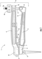
Fig. 1 is a side elevation view of a surgical tool of the invention engaged with a femoral cup and a femoral implant. -
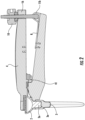
Fig. 2 is a section view ofFig. 1 taken along section lines A. -
Fig. 3 is the same section asFig. 2 after the femoral cup has been released from its Morse taper connection to the femoral implant. -
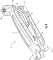
Fig. 4 is a perspective view of the surgical tool ofFig. 1 . -
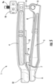
Fig. 5 is a side elevation view of the surgical tool ofFig. 1 . -
Fig. 6 is a perspective view of the lower lever arm of the surgical tool ofFig. 1 . -
Fig. 7 is a side elevation view of the lower lever arm of the surgical tool ofFig. 1 . -
Fig. 8 is a top elevation view of the lower lever arm of the surgical tool ofFig. 1 .# -
Figs. 9A - 9D are perspective views of the underside of the upper lever arm of the surgical tool ofFig. 1 illustrating the rotating turret in different positions of height adjustment,Fig. 9A illustrating the lower height,Fig. 9D illustrating the greatest height andfigs. 9B and 9C illustrating intermediate heights. -
Fig. 10 is a perspective view of a surgical tool of the invention which is used to remove a femoral ball from a femoral implant.Fig. 1 1 is a top elevation view ofFig. 10 . -
Fig. 12 is a side elevation view of the surgical tool ofFig. 10 engaged with a femoral ball and a femoral implant. -
Fig. 12A is a section view ofFig. 12 . - In
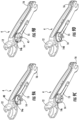
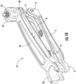
Fig. 1 ,surgical tool 1 is engaged withfemoral cup 2 andfemoral implant 3. More specifically, the distal end ofupper lever arm 4 is engaged withfemoral cup 2 and the distal end oflower lever arm 5 is engaged withfemoral implant 3. In a conventional hip prosthesis, afemoral ball 22 is affixed tofemoral implant 3 in the same manner and position asfemoral cup 2 is affixed tofemoral implant 3. (SeeFigs. 12 and12A .)Femoral cup 2 has aneck 2a andfemoral ball 22 has aneck 22a. The necks have a Morse taper and there is a Morse taper insocket 3a at the open proximal portion ofimplant 3. - Each lever arm comprises multiple components. Referring to
Figs. 1 - 8 and 8A,lower lever arm 5 comprises at its distal end animplant engagement fork 6, a fixedheight adjustment ridge 7, anoptional locking spring 8, and a pivotable drive assembly (described below). Theimplant engagement fork 6 is sized to engage the proximal end of an implantedfemoral implant 3 and prevent theimplant 3 from moving relative to a femoral bone whentool 1 is used to separatefemoral cup 2 fromimplant 3. Fixedheight adjustment ridge 7 works in cooperation with rotating turret 14 (seeFigs. 1- 5 ,9 and 9A ) as discussed in detail below. - The pivotable drive assembly is comprised of a
rod 9 having a threadedproximal portion 9a and apivot pin 1 1 at its distal end. The central axis ofrod 9 is perpendicular to the central axis ofpin 11. Knob 10 is rotatably threaded ontorod 9 and is used to apply or release pressure onarm 4. Whenoptional locking spring 8 is employed, thepivot pin 11 is provided with aflattened portion 11 a which cooperates withspring 8 to maintain the drive assembly in engagement withupper lever arm 4 when desired. Flattenedportion 11b of pivot pin 11 (seeFigs. 2 and3 ) cooperates withspring 8 to maintain the drive assembly out of engagement withupper lever arm 4 when desired. -
Optional locking spring 8 allows movement of the pivotable drive assembly into and out of engagement with the forked proximal end (drive assembly engagement fork 16) ofupper lever arm 4. The spring helps to hold the assembly in or out of the engagement position as desired. - Referring to
Figs. 1 - 5 ,9 and 9A ,upper lever arm 4 comprises at its distal end femoralcup engagement fork 12. The bottom surface oflever arm 4 has a rotatingturret 14 and aturret spring 15. At its proximal end,upper lever arm 4 is provided within driveassembly engagement fork 16. - The illustrated rotating turret 14 (see
Figs. 9A - D ) is comprised of four flat portions, 14a - 14d, but it is understood that it could be comprised of two or more flat portions, including more than the illustrated four flat portions.Spring 15 is biased against the cylindrical upper edge 40 (seeFigs. 3 and9a ) to allow theturret 14 to be rotated by hand while preventing it from rotating freely. Turret 14 rotates on pin 41 (seeFigs 2 and9B ). Eachflat portion 14a - 14d is located in an indentation inturret 14 and each is in a plane in parallel with the plane of the bottom surface oflever arm upper edge 40. The thickness ofturret 14 at each flat portion is different such that the distance from the surface of each flat portion to the bottom surface or underside of the upper lever arm is different. Since the flat portions rest onridge 7, the different thicknesses provide different distances of separation between the lever arms. -
Figs. 10 - 12A illustratesurgical tool 21, the embodiment of the invention which is used in revision surgery on a conventional hip prosthesis to remove a femoral ball from an implanted femoral implant. Comparing the tools of the invention,surgical tool 1 has anupper lever arm 4 with a femoralcup engagement fork 12 adapted to engage a femoral cup. Andsurgical tool 21 has anupper lever arm 24 with a femoralball engagement fork 32 adapted to engage a femoral ball. Otherwise, the elements ofsurgical tool 21 are the same as those ofsurgical tool 1. - Referring to
Figs. 10 - 12A , all of the elements oflower lever arm 5 and the elements affixed thereto are the same as those oftool 1 and they function in the same way.Upper lever arm 24 comprises at its distal end a femoralball engagement fork 32, rotatingturret 14,turret spring 15 and, at its proximal end, driveassembly engagement fork 36. - The femoral cup or femoral ball engagement fork and the femoral implant engagement fork may be referred to generically herein as distal engagement forks.
- The method of using the
surgical tool 1, said method not forming part of the invention, comprises engagingimplant engagement fork 6 withneck 2a offemoral cup 2 and with the proximal end ofimplant 3. Thefork 6 fits loosely aroundneck 2a, the neck serving to locate thefork 6 in position over the proximal end offemoral implant 3. - Then femoral
cup engagement fork 12 is engaged withfemoral cup 2 androtating turret 14 is placed in contact withridge 7. The appropriate position of rotatingturret 14 is then determined and the turret is rotated to the optimum position as explained below. - When
tool 1 is engaged with the femoral implant and the femoral cup, a flat portion, 14a, 14b, 14c or 14d, ofturret 14 rests onridge 7, the turret and the ridge providing a fulcrum for leverage in the operation oftool 1. Each flat portion provides a different distance of separation between the lever arms so that optimum leverage can be achieved depending upon the length of the neck extending beyond the proximal end of the femoral implant, as will be apparent to those having skill in the art. When the turret is rotated into the desired position,turret spring 15 serves to prevent the turret from rotating by itself. After the turret position is selected, the pivotable drive assembly is engaged with the driveassembly engagement fork 16 by pivoting the assembly into a position whererod 9 is brought within thefork 16 andknob 10 is backed off to a position abovefork 16 as illustrated inFigs. 1 and2 . Thenknob 10 is tighteningly rotated to cause the proximal ends oflevers levers Fig. 3 . This tightening rotation ofknob 10 may be referred to herein as actuating the drive assembly. - The method and principles of using
surgical tool 21 are the same as those described above in respect oftool 1, wherein said method and principles of using the tool do not form part of the invention. The only difference being that femoralball engagement fork 32 is engaged withneck 22a offemoral ball 22. - A kit comprising both
surgical tool 1 andsurgical tool 21 may be made up of alower lever arm 5 and its attendant components, anupper lever arm 4 and anupper lever arm 24 so that the kit may be used in revision surgery for a conventional hip prosthesis or a reverse hip prosthesis. The tools of the invention also may comprise an element or elements of a surgical kit which may contain other tools and/or implant elements.
Claims (3)
- A surgical tool (1) for separating a femoral cup (2) or a femoral ball (22) from an implanted femoral implant (3) comprising:an upper lever arm (4) and a lower lever arm (5), the upper lever arm (4) having an upper arm proximal end and an upper arm distal end and the lower lever arm (5) having a lower lever arm proximal end and a lower lever arm distal end;a fulcrum disposed between the proximal and distal ends of the lever arms, the lever arms being in contact at the fulcrum;a femoral cup or femoral ball engagement fork (12) disposed at the distal end of the upper lever arm (4);a femoral implant engagement fork (6) disposed at the distal end of the lower lever arm (5);a drive assembly comprising a rod (9) having a threaded proximal portion (9a) and a knob (10) rotatably threaded thereon,wherein the lever arms (4,5) are separated by an adjustable distance and the fulcrum is comprised of a ridge (7) which cooperates with a rotating turret (14) wherein rotation of the turret (14) allows adjustment of the distance by which the lever arms (4,5) are separated;characterized in thatthe rod (9) further comprises a pivot pin (11) at its distal end pivotably attached to the proximal end of the lower lever arm (5), the upper lever arm (4) having a drive assembly engagement fork at its proximal end, the drive assembly engagement fork being adapted to receive the rod (9) disposed between the knob (10) and the pivot pin (11);wherein one end of a turret spring (15) is biased against a cylindrical upper edge (40) of the rotating turret (14) while the other end is affixed to the upper lever arm (4); andwherein the drive assembly is adapted to cause the proximal ends of the lever arms to move toward one another by means of rotation of the knob (10) when the rod (9) is disposed in the drive assembly engagement fork, thereby causing the distal ends of the lever arms to move away from one another as the lever arms turn on the fulcrum;
andthe rotating turret (14) has two or more flat portions in parallel with an underside of the upper lever arm (4), each flat portion being a different distance from said underside. - The tool of claim 1 for use in a method to separate a femoral cup (2) or a femoral ball (22) from a femoral implant (3).
- A kit comprising the surgical tool of claim 1 and including a femoral cup engagement fork and a femoral ball engagement fork.
Applications Claiming Priority (2)
| Application Number | Priority Date | Filing Date | Title |
|---|---|---|---|
| US201662369901P | 2016-08-02 | 2016-08-02 | |
| PCT/US2017/034948 WO2018026430A1 (en) | 2016-08-02 | 2017-05-30 | Tool and method for separating a femoral cup or a femoral ball from a femoral implant |
Publications (4)
| Publication Number | Publication Date |
|---|---|
| EP3493770A1 EP3493770A1 (en) | 2019-06-12 |
| EP3493770A4 EP3493770A4 (en) | 2020-03-11 |
| EP3493770B1 true EP3493770B1 (en) | 2023-10-04 |
| EP3493770B8 EP3493770B8 (en) | 2023-11-08 |
Family
ID=61073943
Family Applications (1)
| Application Number | Title | Priority Date | Filing Date |
|---|---|---|---|
| EP17837352.8A Active EP3493770B8 (en) | 2016-08-02 | 2017-05-30 | Tool and kit for separating a femoral cup or a femoral ball from a femoral implant |
Country Status (10)
| Country | Link |
|---|---|
| US (1) | US10492929B2 (en) |
| EP (1) | EP3493770B8 (en) |
| JP (1) | JP6923226B2 (en) |
| KR (1) | KR102365374B1 (en) |
| CN (1) | CN109561967B (en) |
| AU (1) | AU2017307544B2 (en) |
| CA (1) | CA3031686C (en) |
| ES (1) | ES2966666T3 (en) |
| WO (1) | WO2018026430A1 (en) |
| ZA (1) | ZA201900699B (en) |
Families Citing this family (8)
| Publication number | Priority date | Publication date | Assignee | Title |
|---|---|---|---|---|
| JP1621250S (en) | 2017-05-22 | 2018-12-25 | ||
| GB201718768D0 (en) * | 2017-11-14 | 2017-12-27 | Univ Oxford Innovation Ltd | Surgical Tool |
| CN109498224B (en) * | 2018-12-21 | 2023-12-12 | 天衍医疗器材有限公司 | Compression bone cement type hip joint prosthesis beating and pulling device |
| CN113286567B (en) | 2019-01-09 | 2024-08-02 | 舒克拉医疗 | Implant extractor |
| RU199717U1 (en) * | 2020-06-15 | 2020-09-16 | Олег Анатольевич Каплунов | Device for removing the head from the neck of the endoprosthesis of the hip joint |
| JP6933871B1 (en) * | 2021-06-01 | 2021-09-08 | 株式会社メドメタレックス | Ball remover |
| EP4119100A4 (en) * | 2021-06-01 | 2023-11-22 | Medmetalex Co., Ltd | Ball removal instrument |
| US20260108363A1 (en) * | 2024-10-22 | 2026-04-23 | Depuy Ireland Unlimited Company | Orthopaedic surgical clamp instruments for taper locking the components of a hip prosthesis during a hip replacement surgical procedure and method of using the same |
Family Cites Families (15)
| Publication number | Priority date | Publication date | Assignee | Title |
|---|---|---|---|---|
| GB1551707A (en) * | 1975-04-28 | 1979-08-30 | Downs Surgical Ltd | Surgical instrument |
| US4457306A (en) | 1982-05-05 | 1984-07-03 | Howmedica, Inc. | Tool and method for engaging two members of a joint prosthesis |
| DE3707097A1 (en) * | 1986-12-05 | 1988-06-09 | S & G Implants Gmbh | PLIERS FOR SPREADING SPINE BODIES |
| JPH0593412U (en) * | 1992-05-25 | 1993-12-21 | 株式会社神戸製鋼所 | Bone head remover |
| US6871549B2 (en) * | 2002-05-09 | 2005-03-29 | Michael A. Serra | Modular implant assembly tool |
| US6786931B2 (en) * | 2002-08-27 | 2004-09-07 | Depuy Products, Inc. | Device, system and method for separation of modular orthopaedic elements |
| US8393254B2 (en) * | 2008-03-04 | 2013-03-12 | Bradshaw Medical, Inc. | Gripping device |
| FR2929830A1 (en) * | 2008-04-15 | 2009-10-16 | Warsaw Orthopedic Inc | SURGICAL TOOL FOR HANDLING AN IMPLANT, ESPECIALLY AN ANCHOR ELEMENT IMPLANTED IN A VERTEBRA |
| US8313531B2 (en) | 2010-03-08 | 2012-11-20 | Hip Innovation Technology Llc | Interlocking reverse hip prosthesis and method |
| EP2665447B1 (en) * | 2011-01-17 | 2016-10-05 | Zimmer, Inc. | Adapter for explant system |
| WO2013022586A1 (en) * | 2011-08-08 | 2013-02-14 | Hip Innovation Technology Llc | Orthpedic instrument, system and method for implanting an acetabular cup |
| CN202313816U (en) * | 2011-11-16 | 2012-07-11 | 天津正天医疗器械有限公司 | Dismantling device for acetabulum nylon inner lining |
| DE102013200924A1 (en) * | 2013-01-22 | 2014-07-24 | Erich Johann Müller | Razor tool for minimally invasive prosthesis revision |
| CN107105638A (en) * | 2014-07-29 | 2017-08-29 | 二十世纪药学股份有限公司 | The method that the cryoprotector of high concentration is imported and removed by vascular perfusion |
| EP3340939B1 (en) * | 2015-08-27 | 2025-10-15 | HIP Innovation Technology, LLC | Surgical trays for removing components of a hip replacement prosthesis |
-
2017
- 2017-05-30 US US15/547,884 patent/US10492929B2/en active Active
- 2017-05-30 KR KR1020197002933A patent/KR102365374B1/en active Active
- 2017-05-30 JP JP2019505161A patent/JP6923226B2/en not_active Expired - Fee Related
- 2017-05-30 AU AU2017307544A patent/AU2017307544B2/en active Active
- 2017-05-30 EP EP17837352.8A patent/EP3493770B8/en active Active
- 2017-05-30 ES ES17837352T patent/ES2966666T3/en active Active
- 2017-05-30 CN CN201780047154.8A patent/CN109561967B/en active Active
- 2017-05-30 WO PCT/US2017/034948 patent/WO2018026430A1/en not_active Ceased
- 2017-05-30 CA CA3031686A patent/CA3031686C/en active Active
-
2019
- 2019-02-01 ZA ZA2019/00699A patent/ZA201900699B/en unknown
Also Published As
| Publication number | Publication date |
|---|---|
| CN109561967B (en) | 2021-07-13 |
| US10492929B2 (en) | 2019-12-03 |
| KR20190114949A (en) | 2019-10-10 |
| BR112019002057A2 (en) | 2019-05-07 |
| NZ750287A (en) | 2021-01-29 |
| AU2017307544A1 (en) | 2019-02-14 |
| EP3493770B8 (en) | 2023-11-08 |
| AU2017307544B2 (en) | 2021-07-22 |
| WO2018026430A1 (en) | 2018-02-08 |
| CA3031686A1 (en) | 2018-02-08 |
| ZA201900699B (en) | 2020-08-26 |
| CA3031686C (en) | 2021-05-25 |
| CN109561967A (en) | 2019-04-02 |
| EP3493770A4 (en) | 2020-03-11 |
| KR102365374B1 (en) | 2022-02-21 |
| US20190142608A1 (en) | 2019-05-16 |
| JP2019527585A (en) | 2019-10-03 |
| ES2966666T3 (en) | 2024-04-23 |
| EP3493770A1 (en) | 2019-06-12 |
| JP6923226B2 (en) | 2021-08-18 |
Similar Documents
| Publication | Publication Date | Title |
|---|---|---|
| AU2017307544B2 (en) | Tool and method for separating a femoral cup or a femoral ball from a femoral implant | |
| US11103365B2 (en) | Surgical trays, instruments and methods for removing components of a hip replacement prosthesis | |
| EP3328289B1 (en) | Tool for separating a femoral cup from an acetabular ball in an implanted hip prosthesis | |
| EP3091943B1 (en) | Instrument for manipulating an implant | |
| CA2992585C (en) | Acetabular cup extractor | |
| EP3328290B1 (en) | Tool for removing an acetabular ball from an acetabular cup in a hip replacement prosthesis | |
| US20180014823A1 (en) | Method of introduction and removal of high concentrations of cryoprotectants by vascular perfusion | |
| NZ750287B2 (en) | Tool and method for separating a femoral cup or a femoral ball from a femoral implant | |
| HK40000296A (en) | Tool and method for separating a femoral cup or a femoral ball from a femoral implant | |
| HK40000296B (en) | Tool and method for separating a femoral cup or a femoral ball from a femoral implant | |
| BR112019002057B1 (en) | SURGICAL TOOL FOR SEPARATING A FEMORAL CUP OR BALL FROM AN IMPLANT FEMORAL IMPLANT, AND, KIT |
Legal Events
| Date | Code | Title | Description |
|---|---|---|---|
| STAA | Information on the status of an ep patent application or granted ep patent |
Free format text: STATUS: THE INTERNATIONAL PUBLICATION HAS BEEN MADE |
|
| PUAI | Public reference made under article 153(3) epc to a published international application that has entered the european phase |
Free format text: ORIGINAL CODE: 0009012 |
|
| STAA | Information on the status of an ep patent application or granted ep patent |
Free format text: STATUS: REQUEST FOR EXAMINATION WAS MADE |
|
| 17P | Request for examination filed |
Effective date: 20190122 |
|
| AK | Designated contracting states |
Kind code of ref document: A1 Designated state(s): AL AT BE BG CH CY CZ DE DK EE ES FI FR GB GR HR HU IE IS IT LI LT LU LV MC MK MT NL NO PL PT RO RS SE SI SK SM TR |
|
| AX | Request for extension of the european patent |
Extension state: BA ME |
|
| DAV | Request for validation of the european patent (deleted) | ||
| DAX | Request for extension of the european patent (deleted) | ||
| A4 | Supplementary search report drawn up and despatched |
Effective date: 20200207 |
|
| RIC1 | Information provided on ipc code assigned before grant |
Ipc: A61F 2/30 20060101AFI20200203BHEP Ipc: A61F 2/34 20060101ALI20200203BHEP Ipc: A61F 2/32 20060101ALI20200203BHEP Ipc: A61F 2/46 20060101ALI20200203BHEP Ipc: A61F 2/36 20060101ALI20200203BHEP |
|
| STAA | Information on the status of an ep patent application or granted ep patent |
Free format text: STATUS: EXAMINATION IS IN PROGRESS |
|
| 17Q | First examination report despatched |
Effective date: 20210111 |
|
| GRAP | Despatch of communication of intention to grant a patent |
Free format text: ORIGINAL CODE: EPIDOSNIGR1 |
|
| STAA | Information on the status of an ep patent application or granted ep patent |
Free format text: STATUS: GRANT OF PATENT IS INTENDED |
|
| GRAS | Grant fee paid |
Free format text: ORIGINAL CODE: EPIDOSNIGR3 |
|
| INTG | Intention to grant announced |
Effective date: 20230801 |
|
| GRAA | (expected) grant |
Free format text: ORIGINAL CODE: 0009210 |
|
| STAA | Information on the status of an ep patent application or granted ep patent |
Free format text: STATUS: THE PATENT HAS BEEN GRANTED |
|
| AK | Designated contracting states |
Kind code of ref document: B1 Designated state(s): AL AT BE BG CH CY CZ DE DK EE ES FI FR GB GR HR HU IE IS IT LI LT LU LV MC MK MT NL NO PL PT RO RS SE SI SK SM TR |
|
| REG | Reference to a national code |
Ref country code: GB Ref legal event code: FG4D |
|
| REG | Reference to a national code |
Ref country code: DE Ref legal event code: R081 Ref document number: 602017074986 Country of ref document: DE Owner name: HIP INNOVATION TECHNOLOGY, LLC, BOCA RATON, US Free format text: FORMER OWNER: HIP INNOVATION TECHNOLOGY, LLC, PLANTATION, FLORIDA, US |
|
| REG | Reference to a national code |
Ref country code: CH Ref legal event code: PK Free format text: BERICHTIGUNG B8 Ref country code: CH Ref legal event code: EP |
|
| REG | Reference to a national code |
Ref country code: IE Ref legal event code: FG4D |
|
| REG | Reference to a national code |
Ref country code: DE Ref legal event code: R096 Ref document number: 602017074986 Country of ref document: DE |
|
| RAP4 | Party data changed (patent owner data changed or rights of a patent transferred) |
Owner name: HIP INNOVATION TECHNOLOGY, LLC |
|
| REG | Reference to a national code |
Ref country code: LT Ref legal event code: MG9D |
|
| REG | Reference to a national code |
Ref country code: NL Ref legal event code: MP Effective date: 20231004 |
|
| PG25 | Lapsed in a contracting state [announced via postgrant information from national office to epo] |
Ref country code: NL Free format text: LAPSE BECAUSE OF FAILURE TO SUBMIT A TRANSLATION OF THE DESCRIPTION OR TO PAY THE FEE WITHIN THE PRESCRIBED TIME-LIMIT Effective date: 20231004 |
|
| PG25 | Lapsed in a contracting state [announced via postgrant information from national office to epo] |
Ref country code: GR Free format text: LAPSE BECAUSE OF FAILURE TO SUBMIT A TRANSLATION OF THE DESCRIPTION OR TO PAY THE FEE WITHIN THE PRESCRIBED TIME-LIMIT Effective date: 20240105 |
|
| PG25 | Lapsed in a contracting state [announced via postgrant information from national office to epo] |
Ref country code: IS Free format text: LAPSE BECAUSE OF FAILURE TO SUBMIT A TRANSLATION OF THE DESCRIPTION OR TO PAY THE FEE WITHIN THE PRESCRIBED TIME-LIMIT Effective date: 20240204 |
|
| PG25 | Lapsed in a contracting state [announced via postgrant information from national office to epo] |
Ref country code: LT Free format text: LAPSE BECAUSE OF FAILURE TO SUBMIT A TRANSLATION OF THE DESCRIPTION OR TO PAY THE FEE WITHIN THE PRESCRIBED TIME-LIMIT Effective date: 20231004 |
|
| REG | Reference to a national code |
Ref country code: ES Ref legal event code: FG2A Ref document number: 2966666 Country of ref document: ES Kind code of ref document: T3 Effective date: 20240423 |
|
| PG25 | Lapsed in a contracting state [announced via postgrant information from national office to epo] |
Ref country code: LT Free format text: LAPSE BECAUSE OF FAILURE TO SUBMIT A TRANSLATION OF THE DESCRIPTION OR TO PAY THE FEE WITHIN THE PRESCRIBED TIME-LIMIT Effective date: 20231004 Ref country code: IS Free format text: LAPSE BECAUSE OF FAILURE TO SUBMIT A TRANSLATION OF THE DESCRIPTION OR TO PAY THE FEE WITHIN THE PRESCRIBED TIME-LIMIT Effective date: 20240204 Ref country code: GR Free format text: LAPSE BECAUSE OF FAILURE TO SUBMIT A TRANSLATION OF THE DESCRIPTION OR TO PAY THE FEE WITHIN THE PRESCRIBED TIME-LIMIT Effective date: 20240105 Ref country code: BG Free format text: LAPSE BECAUSE OF FAILURE TO SUBMIT A TRANSLATION OF THE DESCRIPTION OR TO PAY THE FEE WITHIN THE PRESCRIBED TIME-LIMIT Effective date: 20240104 Ref country code: PT Free format text: LAPSE BECAUSE OF FAILURE TO SUBMIT A TRANSLATION OF THE DESCRIPTION OR TO PAY THE FEE WITHIN THE PRESCRIBED TIME-LIMIT Effective date: 20240205 |
|
| PG25 | Lapsed in a contracting state [announced via postgrant information from national office to epo] |
Ref country code: SE Free format text: LAPSE BECAUSE OF FAILURE TO SUBMIT A TRANSLATION OF THE DESCRIPTION OR TO PAY THE FEE WITHIN THE PRESCRIBED TIME-LIMIT Effective date: 20231004 Ref country code: RS Free format text: LAPSE BECAUSE OF FAILURE TO SUBMIT A TRANSLATION OF THE DESCRIPTION OR TO PAY THE FEE WITHIN THE PRESCRIBED TIME-LIMIT Effective date: 20231004 Ref country code: PL Free format text: LAPSE BECAUSE OF FAILURE TO SUBMIT A TRANSLATION OF THE DESCRIPTION OR TO PAY THE FEE WITHIN THE PRESCRIBED TIME-LIMIT Effective date: 20231004 Ref country code: NO Free format text: LAPSE BECAUSE OF FAILURE TO SUBMIT A TRANSLATION OF THE DESCRIPTION OR TO PAY THE FEE WITHIN THE PRESCRIBED TIME-LIMIT Effective date: 20240104 Ref country code: LV Free format text: LAPSE BECAUSE OF FAILURE TO SUBMIT A TRANSLATION OF THE DESCRIPTION OR TO PAY THE FEE WITHIN THE PRESCRIBED TIME-LIMIT Effective date: 20231004 Ref country code: HR Free format text: LAPSE BECAUSE OF FAILURE TO SUBMIT A TRANSLATION OF THE DESCRIPTION OR TO PAY THE FEE WITHIN THE PRESCRIBED TIME-LIMIT Effective date: 20231004 |
|
| REG | Reference to a national code |
Ref country code: DE Ref legal event code: R097 Ref document number: 602017074986 Country of ref document: DE |
|
| PG25 | Lapsed in a contracting state [announced via postgrant information from national office to epo] |
Ref country code: DK Free format text: LAPSE BECAUSE OF FAILURE TO SUBMIT A TRANSLATION OF THE DESCRIPTION OR TO PAY THE FEE WITHIN THE PRESCRIBED TIME-LIMIT Effective date: 20231004 |
|
| PG25 | Lapsed in a contracting state [announced via postgrant information from national office to epo] |
Ref country code: CZ Free format text: LAPSE BECAUSE OF FAILURE TO SUBMIT A TRANSLATION OF THE DESCRIPTION OR TO PAY THE FEE WITHIN THE PRESCRIBED TIME-LIMIT Effective date: 20231004 |
|
| PG25 | Lapsed in a contracting state [announced via postgrant information from national office to epo] |
Ref country code: SK Free format text: LAPSE BECAUSE OF FAILURE TO SUBMIT A TRANSLATION OF THE DESCRIPTION OR TO PAY THE FEE WITHIN THE PRESCRIBED TIME-LIMIT Effective date: 20231004 |
|
| PG25 | Lapsed in a contracting state [announced via postgrant information from national office to epo] |
Ref country code: SM Free format text: LAPSE BECAUSE OF FAILURE TO SUBMIT A TRANSLATION OF THE DESCRIPTION OR TO PAY THE FEE WITHIN THE PRESCRIBED TIME-LIMIT Effective date: 20231004 Ref country code: SK Free format text: LAPSE BECAUSE OF FAILURE TO SUBMIT A TRANSLATION OF THE DESCRIPTION OR TO PAY THE FEE WITHIN THE PRESCRIBED TIME-LIMIT Effective date: 20231004 Ref country code: RO Free format text: LAPSE BECAUSE OF FAILURE TO SUBMIT A TRANSLATION OF THE DESCRIPTION OR TO PAY THE FEE WITHIN THE PRESCRIBED TIME-LIMIT Effective date: 20231004 Ref country code: EE Free format text: LAPSE BECAUSE OF FAILURE TO SUBMIT A TRANSLATION OF THE DESCRIPTION OR TO PAY THE FEE WITHIN THE PRESCRIBED TIME-LIMIT Effective date: 20231004 Ref country code: DK Free format text: LAPSE BECAUSE OF FAILURE TO SUBMIT A TRANSLATION OF THE DESCRIPTION OR TO PAY THE FEE WITHIN THE PRESCRIBED TIME-LIMIT Effective date: 20231004 Ref country code: CZ Free format text: LAPSE BECAUSE OF FAILURE TO SUBMIT A TRANSLATION OF THE DESCRIPTION OR TO PAY THE FEE WITHIN THE PRESCRIBED TIME-LIMIT Effective date: 20231004 |
|
| PLBE | No opposition filed within time limit |
Free format text: ORIGINAL CODE: 0009261 |
|
| STAA | Information on the status of an ep patent application or granted ep patent |
Free format text: STATUS: NO OPPOSITION FILED WITHIN TIME LIMIT |
|
| 26N | No opposition filed |
Effective date: 20240705 |
|
| PG25 | Lapsed in a contracting state [announced via postgrant information from national office to epo] |
Ref country code: SI Free format text: LAPSE BECAUSE OF FAILURE TO SUBMIT A TRANSLATION OF THE DESCRIPTION OR TO PAY THE FEE WITHIN THE PRESCRIBED TIME-LIMIT Effective date: 20231004 |
|
| PG25 | Lapsed in a contracting state [announced via postgrant information from national office to epo] |
Ref country code: SI Free format text: LAPSE BECAUSE OF FAILURE TO SUBMIT A TRANSLATION OF THE DESCRIPTION OR TO PAY THE FEE WITHIN THE PRESCRIBED TIME-LIMIT Effective date: 20231004 |
|
| PG25 | Lapsed in a contracting state [announced via postgrant information from national office to epo] |
Ref country code: MC Free format text: LAPSE BECAUSE OF FAILURE TO SUBMIT A TRANSLATION OF THE DESCRIPTION OR TO PAY THE FEE WITHIN THE PRESCRIBED TIME-LIMIT Effective date: 20231004 |
|
| PG25 | Lapsed in a contracting state [announced via postgrant information from national office to epo] |
Ref country code: MC Free format text: LAPSE BECAUSE OF FAILURE TO SUBMIT A TRANSLATION OF THE DESCRIPTION OR TO PAY THE FEE WITHIN THE PRESCRIBED TIME-LIMIT Effective date: 20231004 |
|
| PG25 | Lapsed in a contracting state [announced via postgrant information from national office to epo] |
Ref country code: CY Free format text: LAPSE BECAUSE OF FAILURE TO SUBMIT A TRANSLATION OF THE DESCRIPTION OR TO PAY THE FEE WITHIN THE PRESCRIBED TIME-LIMIT; INVALID AB INITIO Effective date: 20170530 |
|
| PGFP | Annual fee paid to national office [announced via postgrant information from national office to epo] |
Ref country code: LU Payment date: 20250821 Year of fee payment: 9 |
|
| PG25 | Lapsed in a contracting state [announced via postgrant information from national office to epo] |
Ref country code: FI Free format text: LAPSE BECAUSE OF FAILURE TO SUBMIT A TRANSLATION OF THE DESCRIPTION OR TO PAY THE FEE WITHIN THE PRESCRIBED TIME-LIMIT Effective date: 20231004 |
|
| PGFP | Annual fee paid to national office [announced via postgrant information from national office to epo] |
Ref country code: ES Payment date: 20250821 Year of fee payment: 9 |
|
| PGFP | Annual fee paid to national office [announced via postgrant information from national office to epo] |
Ref country code: DE Payment date: 20250820 Year of fee payment: 9 |
|
| PGFP | Annual fee paid to national office [announced via postgrant information from national office to epo] |
Ref country code: TR Payment date: 20250828 Year of fee payment: 9 Ref country code: IT Payment date: 20250825 Year of fee payment: 9 |
|
| REG | Reference to a national code |
Ref country code: AT Ref legal event code: UEP Ref document number: 1616943 Country of ref document: AT Kind code of ref document: T Effective date: 20231004 |
|
| PGFP | Annual fee paid to national office [announced via postgrant information from national office to epo] |
Ref country code: BE Payment date: 20250825 Year of fee payment: 9 Ref country code: GB Payment date: 20250820 Year of fee payment: 9 |
|
| PGFP | Annual fee paid to national office [announced via postgrant information from national office to epo] |
Ref country code: FR Payment date: 20250820 Year of fee payment: 10 Ref country code: AT Payment date: 20250821 Year of fee payment: 9 |
|
| PGFP | Annual fee paid to national office [announced via postgrant information from national office to epo] |
Ref country code: CH Payment date: 20250820 Year of fee payment: 9 |
|
| PGFP | Annual fee paid to national office [announced via postgrant information from national office to epo] |
Ref country code: IE Payment date: 20250820 Year of fee payment: 9 |
|
| PG25 | Lapsed in a contracting state [announced via postgrant information from national office to epo] |
Ref country code: HU Free format text: LAPSE BECAUSE OF FAILURE TO SUBMIT A TRANSLATION OF THE DESCRIPTION OR TO PAY THE FEE WITHIN THE PRESCRIBED TIME-LIMIT; INVALID AB INITIO Effective date: 20170530 |