EP3328290B1 - Tool for removing an acetabular ball from an acetabular cup in a hip replacement prosthesis - Google Patents
Tool for removing an acetabular ball from an acetabular cup in a hip replacement prosthesis Download PDFInfo
- Publication number
- EP3328290B1 EP3328290B1 EP16831034.0A EP16831034A EP3328290B1 EP 3328290 B1 EP3328290 B1 EP 3328290B1 EP 16831034 A EP16831034 A EP 16831034A EP 3328290 B1 EP3328290 B1 EP 3328290B1
- Authority
- EP
- European Patent Office
- Prior art keywords
- jaw
- tool
- shaft
- nut
- acetabular
- Prior art date
- Legal status (The legal status is an assumption and is not a legal conclusion. Google has not performed a legal analysis and makes no representation as to the accuracy of the status listed.)
- Active
Links
- 238000011540 hip replacement Methods 0.000 title 1
- 210000001624 hip Anatomy 0.000 description 2
- 210000000588 acetabulum Anatomy 0.000 description 1
- 210000000988 bone and bone Anatomy 0.000 description 1
- 238000000605 extraction Methods 0.000 description 1
- 238000000034 method Methods 0.000 description 1
- 238000001356 surgical procedure Methods 0.000 description 1
Images
Classifications
-
- A—HUMAN NECESSITIES
- A61—MEDICAL OR VETERINARY SCIENCE; HYGIENE
- A61F—FILTERS IMPLANTABLE INTO BLOOD VESSELS; PROSTHESES; DEVICES PROVIDING PATENCY TO, OR PREVENTING COLLAPSING OF, TUBULAR STRUCTURES OF THE BODY, e.g. STENTS; ORTHOPAEDIC, NURSING OR CONTRACEPTIVE DEVICES; FOMENTATION; TREATMENT OR PROTECTION OF EYES OR EARS; BANDAGES, DRESSINGS OR ABSORBENT PADS; FIRST-AID KITS
- A61F2/00—Filters implantable into blood vessels; Prostheses, i.e. artificial substitutes or replacements for parts of the body; Appliances for connecting them with the body; Devices providing patency to, or preventing collapsing of, tubular structures of the body, e.g. stents
- A61F2/02—Prostheses implantable into the body
- A61F2/30—Joints
- A61F2/46—Special tools or methods for implanting or extracting artificial joints, accessories, bone grafts or substitutes, or particular adaptations therefor
- A61F2/4637—Special tools or methods for implanting or extracting artificial joints, accessories, bone grafts or substitutes, or particular adaptations therefor for connecting or disconnecting two parts of a prosthesis
-
- A—HUMAN NECESSITIES
- A61—MEDICAL OR VETERINARY SCIENCE; HYGIENE
- A61B—DIAGNOSIS; SURGERY; IDENTIFICATION
- A61B17/00—Surgical instruments, devices or methods, e.g. tourniquets
- A61B17/56—Surgical instruments or methods for treatment of bones or joints; Devices specially adapted therefor
- A61B17/58—Surgical instruments or methods for treatment of bones or joints; Devices specially adapted therefor for osteosynthesis, e.g. bone plates, screws, setting implements or the like
- A61B17/88—Osteosynthesis instruments; Methods or means for implanting or extracting internal or external fixation devices
- A61B17/92—Impactors or extractors, e.g. for removing intramedullary devices
-
- A—HUMAN NECESSITIES
- A61—MEDICAL OR VETERINARY SCIENCE; HYGIENE
- A61F—FILTERS IMPLANTABLE INTO BLOOD VESSELS; PROSTHESES; DEVICES PROVIDING PATENCY TO, OR PREVENTING COLLAPSING OF, TUBULAR STRUCTURES OF THE BODY, e.g. STENTS; ORTHOPAEDIC, NURSING OR CONTRACEPTIVE DEVICES; FOMENTATION; TREATMENT OR PROTECTION OF EYES OR EARS; BANDAGES, DRESSINGS OR ABSORBENT PADS; FIRST-AID KITS
- A61F2/00—Filters implantable into blood vessels; Prostheses, i.e. artificial substitutes or replacements for parts of the body; Appliances for connecting them with the body; Devices providing patency to, or preventing collapsing of, tubular structures of the body, e.g. stents
- A61F2/02—Prostheses implantable into the body
- A61F2/30—Joints
- A61F2/46—Special tools or methods for implanting or extracting artificial joints, accessories, bone grafts or substitutes, or particular adaptations therefor
- A61F2/4603—Special tools or methods for implanting or extracting artificial joints, accessories, bone grafts or substitutes, or particular adaptations therefor for insertion or extraction of endoprosthetic joints or of accessories thereof
- A61F2/4609—Special tools or methods for implanting or extracting artificial joints, accessories, bone grafts or substitutes, or particular adaptations therefor for insertion or extraction of endoprosthetic joints or of accessories thereof of acetabular cups
-
- A—HUMAN NECESSITIES
- A61—MEDICAL OR VETERINARY SCIENCE; HYGIENE
- A61B—DIAGNOSIS; SURGERY; IDENTIFICATION
- A61B17/00—Surgical instruments, devices or methods, e.g. tourniquets
- A61B17/56—Surgical instruments or methods for treatment of bones or joints; Devices specially adapted therefor
- A61B2017/564—Methods for bone or joint treatment
-
- A—HUMAN NECESSITIES
- A61—MEDICAL OR VETERINARY SCIENCE; HYGIENE
- A61F—FILTERS IMPLANTABLE INTO BLOOD VESSELS; PROSTHESES; DEVICES PROVIDING PATENCY TO, OR PREVENTING COLLAPSING OF, TUBULAR STRUCTURES OF THE BODY, e.g. STENTS; ORTHOPAEDIC, NURSING OR CONTRACEPTIVE DEVICES; FOMENTATION; TREATMENT OR PROTECTION OF EYES OR EARS; BANDAGES, DRESSINGS OR ABSORBENT PADS; FIRST-AID KITS
- A61F2/00—Filters implantable into blood vessels; Prostheses, i.e. artificial substitutes or replacements for parts of the body; Appliances for connecting them with the body; Devices providing patency to, or preventing collapsing of, tubular structures of the body, e.g. stents
- A61F2/02—Prostheses implantable into the body
- A61F2/30—Joints
- A61F2/46—Special tools or methods for implanting or extracting artificial joints, accessories, bone grafts or substitutes, or particular adaptations therefor
- A61F2/4603—Special tools or methods for implanting or extracting artificial joints, accessories, bone grafts or substitutes, or particular adaptations therefor for insertion or extraction of endoprosthetic joints or of accessories thereof
-
- A—HUMAN NECESSITIES
- A61—MEDICAL OR VETERINARY SCIENCE; HYGIENE
- A61F—FILTERS IMPLANTABLE INTO BLOOD VESSELS; PROSTHESES; DEVICES PROVIDING PATENCY TO, OR PREVENTING COLLAPSING OF, TUBULAR STRUCTURES OF THE BODY, e.g. STENTS; ORTHOPAEDIC, NURSING OR CONTRACEPTIVE DEVICES; FOMENTATION; TREATMENT OR PROTECTION OF EYES OR EARS; BANDAGES, DRESSINGS OR ABSORBENT PADS; FIRST-AID KITS
- A61F2/00—Filters implantable into blood vessels; Prostheses, i.e. artificial substitutes or replacements for parts of the body; Appliances for connecting them with the body; Devices providing patency to, or preventing collapsing of, tubular structures of the body, e.g. stents
- A61F2/02—Prostheses implantable into the body
- A61F2/30—Joints
- A61F2002/30001—Additional features of subject-matter classified in A61F2/28, A61F2/30 and subgroups thereof
- A61F2002/30621—Features concerning the anatomical functioning or articulation of the prosthetic joint
- A61F2002/30649—Ball-and-socket joints
-
- A—HUMAN NECESSITIES
- A61—MEDICAL OR VETERINARY SCIENCE; HYGIENE
- A61F—FILTERS IMPLANTABLE INTO BLOOD VESSELS; PROSTHESES; DEVICES PROVIDING PATENCY TO, OR PREVENTING COLLAPSING OF, TUBULAR STRUCTURES OF THE BODY, e.g. STENTS; ORTHOPAEDIC, NURSING OR CONTRACEPTIVE DEVICES; FOMENTATION; TREATMENT OR PROTECTION OF EYES OR EARS; BANDAGES, DRESSINGS OR ABSORBENT PADS; FIRST-AID KITS
- A61F2/00—Filters implantable into blood vessels; Prostheses, i.e. artificial substitutes or replacements for parts of the body; Appliances for connecting them with the body; Devices providing patency to, or preventing collapsing of, tubular structures of the body, e.g. stents
- A61F2/02—Prostheses implantable into the body
- A61F2/30—Joints
- A61F2/32—Joints for the hip
- A61F2/34—Acetabular cups
- A61F2002/348—Additional features
- A61F2002/3483—Additional features having a convex shape, e.g. hemispherical heads
-
- A—HUMAN NECESSITIES
- A61—MEDICAL OR VETERINARY SCIENCE; HYGIENE
- A61F—FILTERS IMPLANTABLE INTO BLOOD VESSELS; PROSTHESES; DEVICES PROVIDING PATENCY TO, OR PREVENTING COLLAPSING OF, TUBULAR STRUCTURES OF THE BODY, e.g. STENTS; ORTHOPAEDIC, NURSING OR CONTRACEPTIVE DEVICES; FOMENTATION; TREATMENT OR PROTECTION OF EYES OR EARS; BANDAGES, DRESSINGS OR ABSORBENT PADS; FIRST-AID KITS
- A61F2/00—Filters implantable into blood vessels; Prostheses, i.e. artificial substitutes or replacements for parts of the body; Appliances for connecting them with the body; Devices providing patency to, or preventing collapsing of, tubular structures of the body, e.g. stents
- A61F2/02—Prostheses implantable into the body
- A61F2/30—Joints
- A61F2/46—Special tools or methods for implanting or extracting artificial joints, accessories, bone grafts or substitutes, or particular adaptations therefor
- A61F2/4603—Special tools or methods for implanting or extracting artificial joints, accessories, bone grafts or substitutes, or particular adaptations therefor for insertion or extraction of endoprosthetic joints or of accessories thereof
- A61F2002/4619—Special tools or methods for implanting or extracting artificial joints, accessories, bone grafts or substitutes, or particular adaptations therefor for insertion or extraction of endoprosthetic joints or of accessories thereof for extraction
-
- A—HUMAN NECESSITIES
- A61—MEDICAL OR VETERINARY SCIENCE; HYGIENE
- A61F—FILTERS IMPLANTABLE INTO BLOOD VESSELS; PROSTHESES; DEVICES PROVIDING PATENCY TO, OR PREVENTING COLLAPSING OF, TUBULAR STRUCTURES OF THE BODY, e.g. STENTS; ORTHOPAEDIC, NURSING OR CONTRACEPTIVE DEVICES; FOMENTATION; TREATMENT OR PROTECTION OF EYES OR EARS; BANDAGES, DRESSINGS OR ABSORBENT PADS; FIRST-AID KITS
- A61F2/00—Filters implantable into blood vessels; Prostheses, i.e. artificial substitutes or replacements for parts of the body; Appliances for connecting them with the body; Devices providing patency to, or preventing collapsing of, tubular structures of the body, e.g. stents
- A61F2/02—Prostheses implantable into the body
- A61F2/30—Joints
- A61F2/46—Special tools or methods for implanting or extracting artificial joints, accessories, bone grafts or substitutes, or particular adaptations therefor
- A61F2/4603—Special tools or methods for implanting or extracting artificial joints, accessories, bone grafts or substitutes, or particular adaptations therefor for insertion or extraction of endoprosthetic joints or of accessories thereof
- A61F2002/4625—Special tools or methods for implanting or extracting artificial joints, accessories, bone grafts or substitutes, or particular adaptations therefor for insertion or extraction of endoprosthetic joints or of accessories thereof with relative movement between parts of the instrument during use
- A61F2002/4627—Special tools or methods for implanting or extracting artificial joints, accessories, bone grafts or substitutes, or particular adaptations therefor for insertion or extraction of endoprosthetic joints or of accessories thereof with relative movement between parts of the instrument during use with linear motion along or rotating motion about the instrument axis or the implantation direction, e.g. telescopic, along a guiding rod, screwing inside the instrument
-
- A—HUMAN NECESSITIES
- A61—MEDICAL OR VETERINARY SCIENCE; HYGIENE
- A61F—FILTERS IMPLANTABLE INTO BLOOD VESSELS; PROSTHESES; DEVICES PROVIDING PATENCY TO, OR PREVENTING COLLAPSING OF, TUBULAR STRUCTURES OF THE BODY, e.g. STENTS; ORTHOPAEDIC, NURSING OR CONTRACEPTIVE DEVICES; FOMENTATION; TREATMENT OR PROTECTION OF EYES OR EARS; BANDAGES, DRESSINGS OR ABSORBENT PADS; FIRST-AID KITS
- A61F2/00—Filters implantable into blood vessels; Prostheses, i.e. artificial substitutes or replacements for parts of the body; Appliances for connecting them with the body; Devices providing patency to, or preventing collapsing of, tubular structures of the body, e.g. stents
- A61F2/02—Prostheses implantable into the body
- A61F2/30—Joints
- A61F2/46—Special tools or methods for implanting or extracting artificial joints, accessories, bone grafts or substitutes, or particular adaptations therefor
- A61F2/4637—Special tools or methods for implanting or extracting artificial joints, accessories, bone grafts or substitutes, or particular adaptations therefor for connecting or disconnecting two parts of a prosthesis
- A61F2002/4641—Special tools or methods for implanting or extracting artificial joints, accessories, bone grafts or substitutes, or particular adaptations therefor for connecting or disconnecting two parts of a prosthesis for disconnecting
Definitions
- the present invention relates to surgical tools used in connection with a reverse hip prosthesis. More particularly, the invention has to do with a surgical tool for extracting an acetabular ball from an acetabular cup.
- a reverse hip prosthesis is described in U.S. Patents Nos. 8,313,531 B2 and 8,540,779 B2 .
- the prosthesis and a revision surgery method also are described in U.S. Patent No. 8,992,627 B2 .
- U.S. Patent No. 5,938,701 A discloses an extraction device for removing a socket bearing insert from an acetabular cup in an acetabular prosthesis in which an extracting member is adapted for attachment to a groove in the insert.
- the acetabular ball is affixed by means of a Morse taper to an acetabular cup stem.
- the stem extends from the bottom of a concave surface of the acetabular cup.
- the surgical tool of the invention enables a surgeon to remove the acetabular ball from an implanted prosthesis without pulling on the acetabular cup and without disrupting any bone ingrowth.
- acetabular ball extractor from time to time to describe the tool of the invention and the term "tool” or “instrument” is sometimes used to refer to either or both of the first and second embodiments of the invention.
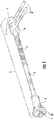
- the tool 1 is the first embodiment of the tool of the invention and is illustrated in perspective in Fig. 1 .
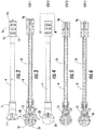
- the tool 1a is the second embodiment of the tool of the invention and is illustrated in a partially exploded view in Fig. 12 and in elevation in Fig. 2 .
- the tool 1 comprises a jaw shaft 10 having two or more than two jaws 2 disposed at the distal end thereof. Each jaw 2 is pivotable about a pin 2 having an axis perpendicular to a central axis of jaw shaft 10. And jaw shaft 10 has a threaded proximal end 11. (See Figs. 8 , 12 and 2A .)
- the jaw shaft 10 is disposed concentrically in outer shaft 4.
- a bell shaped element, referred to herein as handle bell 3 is affixed to the distal end of outer shaft 4.
- the handle bell 3 is internally sized to cause jaws 2 to close as the jaws 2 are drawn into the handle bell 3 by proximal movement of jaw shaft 10 toward the proximal end of the tool 1 as explained in more detail below.
- the handle bell 3 has a circumferential bell edge 33 at its distal end sized to engage a circumferential cup edge 23 of an acetabular cup.
- Outer shaft 4 has an optional knurled portion 5.
- a jaw shaft nut 9 or 9a is threaded onto the proximal end of jaw shaft 0 and an outer shaft nut 6 or 6a is affixed to the proximal end of outer shaft 4.
- the jaw shaft nut abuts the outer shaft nut and the threads at the proximal end of shaft 4 are right handed, tightening jaw shaft nut 9 or 9a by turning it in a clockwise (or right-handed) direction will exert a distal force on nut 6 or 6a causing the jaw shaft 10 to move in a proximal direction relative to the outer shaft 4.
- the nuts are disposed adjacent to one another with the jaw shaft nut 9 or 9a being disposed proximally to the outer shaft nut 6 or 6a.
- Jaw shaft 10 is illustrated in section in Figs. 3, 5 and 6 , and in elevation in Fig.8 .
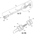
- Figs. 12 and 12A illustrate the threaded proximal end 1 of jaw shaft 10;
- Fig. 12A being a magnified view of the proximal end A of the tool illustrated in Fig. 12 .
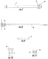
- Fig. 7 is an elevation view of outer shaft 4 with an outer shaft nut 6a thereon.
- the jaw shaft 10 is illustrated in elevation in Fig. 8 with jaws 2 thereon and a block bar 8 is illustrated in elevation in Fig. 9.
- Figs. 10 and 11 are elevations of handle bell 3 and jaw shaft nut 9a, respectively.
- the difference between tools 1 and 1a has to do with differences in outer shaft nuts 6 and 6a and jaw shaft nuts 9 and 9a.
- Nuts 6 and 9 are knurled and holes 7 are provided in the knurled portions to receive block bars 8 which are used to provide leverage in the operation of the tool.
- Nuts 6a and 9a are also knurled but they are additionally provided with hex portions 14 and 15, respectively.
- Holes 7a are provided for block bars 8 in hex portions 14 and 15.
- the hex portions allow the surgeon to use a wrench or wrenches (not shown) instead of some or all of the block bars in order to obtain increased leverage during operation of the tool.
- flattened portions on the outer surface of the nuts having shapes other than a hex can be used to permit use of a wrench or other tool in order to obtain increased leverage as will be apparent to those having ordinary skill in the art.
- Figs. 3-6 Also disclosed is the operation of the tool, which operation is illustrated in Figs. 3-6 .
- the jaws 2 are allowed to open when jaw shaft 10 is pushed in a distal direction while holding shaft 4 so that the jaws move out of handle bell 3.
- the jaws 2 are hinged by pins 12.
- Fig. 3 the jaws 2 are shown in section after they have been pushed out of handle bell 3 and pushed over acetabular ball 20.
- Acetabular ball 20 is securely affixed by means of a Morse taper on stem 21.
- Stem 21 is affixed to and extends from the concave surface off acetabular cup 22.
- Figs. 4 and 5 the circumferential bell edge 33 at the distal end of handle bell 3 has been pushed into engagement with the circumferential cup edge 23 of acetabular cup 22.
- the next step is to grip shaft 4 while turning jaw shaft nut 9 or 9a causing the jaw shaft to move in a proximal direction so that jaws 2 pull on acetabular ball 20 while handle bell 3 exerts an opposing force on the circumferential cup edge 23 of acetabular cup 22.
- the opposing force prevents pulling on acetabular cup 22 so that the cup is not pulled out of the acetabulum.
- a rod or block bar 8 is placed in a hole 7 or 7a of outer shaft nut 6 or 6a and another rod or block bar 8 is placed in a hole 7 or 7a of jaw shaft nut 9 or 9a when additional leverage is needed to exert a pulling force on acetabular ball 20 and an opposing pushing force on acetabular cup 22.
- the holes 7 and 7a are perpendicular to the central axes of the nuts. If more leverage is needed, the block bars 8 are removed from one or both of shaft nuts 6a or 9a and a wrench is used on either or both shaft nuts by placing the open end of the wrench(es) (not shown) over one or both hex portions 14 or 15. When sufficient force is exerted, the ball separates from stem 21 as illustrated by space 30 in Fig. 6 .
Description
- The present invention relates to surgical tools used in connection with a reverse hip prosthesis. More particularly, the invention has to do with a surgical tool for extracting an acetabular ball from an acetabular cup.
- A reverse hip prosthesis is described in
U.S. Patents Nos. 8,313,531 B2 and8,540,779 B2 . The prosthesis and a revision surgery method also are described inU.S. Patent No. 8,992,627 B2 . -
U.S. Patent No. 5,938,701 A discloses an extraction device for removing a socket bearing insert from an acetabular cup in an acetabular prosthesis in which an extracting member is adapted for attachment to a groove in the insert. - As described in the patents referenced above, the acetabular ball is affixed by means of a Morse taper to an acetabular cup stem. The stem extends from the bottom of a concave surface of the acetabular cup. The surgical tool of the invention enables a surgeon to remove the acetabular ball from an implanted prosthesis without pulling on the acetabular cup and without disrupting any bone ingrowth. In the present disclosure, we use the term "acetabular ball extractor" from time to time to describe the tool of the invention and the term "tool" or "instrument" is sometimes used to refer to either or both of the first and second embodiments of the invention.
-
Fig. 1 is a perspective view of a first embodiment of the surgical tool of the invention. -
Fig. 2 is an elevation view of a second embodiment of the tool. -
Fig. 3 is a section view of the tool in a first step illustrating the jaws positioned over an acetabular ball which has been affixed in an acetabular cup. -
Fig. 4 is an elevation view of the tool in a second step fully engaged with the acetabular ball and cup. -
Fig. 5 is a section view ofFig. 4 taken along section line A-A. -
Fig. 6 is a section view of the tool in a third step illustrating an acetabular ball separated from the stem of the acetabular cup. -
Fig. 7 is an elevation view of a handle or outer shaft for the acetabular ball extractor. -
Fig. 8 is an elevation view of a jaw assembly of the acetabular ball extractor. -
Fig. 9 is an elevation view of a block bar of the acetabular ball extractor. -
Fig. 10 is an elevation view of the handle bell of the acetabular ball extractor. -
Fig. 11 is an elevation view of a shaft nut of the second embodiment of the acetabular ball extractor. -
Fig. 12 is a partially exploded view of the second embodiment of the tool of the invention. -
Fig. 12A is a magnified view of the proximal end ofFig. 12 . - The
tool 1 is the first embodiment of the tool of the invention and is illustrated in perspective inFig. 1 . The tool 1a is the second embodiment of the tool of the invention and is illustrated in a partially exploded view inFig. 12 and in elevation inFig. 2 . - Referring to
Figs. 1-6 , thetool 1 comprises ajaw shaft 10 having two or more than twojaws 2 disposed at the distal end thereof. Eachjaw 2 is pivotable about apin 2 having an axis perpendicular to a central axis ofjaw shaft 10. Andjaw shaft 10 has a threadedproximal end 11. (SeeFigs. 8 ,12 and2A .) Thejaw shaft 10 is disposed concentrically inouter shaft 4. A bell shaped element, referred to herein ashandle bell 3, is affixed to the distal end ofouter shaft 4. Thehandle bell 3 is internally sized to causejaws 2 to close as thejaws 2 are drawn into thehandle bell 3 by proximal movement ofjaw shaft 10 toward the proximal end of thetool 1 as explained in more detail below. Thehandle bell 3 has acircumferential bell edge 33 at its distal end sized to engage acircumferential cup edge 23 of an acetabular cup.Outer shaft 4 has an optional knurledportion 5. - A
jaw shaft nut 9 or 9a is threaded onto the proximal end of jaw shaft 0 and an outer shaft nut 6 or 6a is affixed to the proximal end ofouter shaft 4. When the jaw shaft nut abuts the outer shaft nut and the threads at the proximal end ofshaft 4 are right handed, tighteningjaw shaft nut 9 or 9a by turning it in a clockwise (or right-handed) direction will exert a distal force on nut 6 or 6a causing thejaw shaft 10 to move in a proximal direction relative to theouter shaft 4. By way of further explanation, the nuts are disposed adjacent to one another with thejaw shaft nut 9 or 9a being disposed proximally to the outer shaft nut 6 or 6a. Jawshaft 10 is illustrated in section inFigs. 3, 5 and 6 , and in elevation inFig.8 .Figs. 12 and 12A illustrate the threadedproximal end 1 ofjaw shaft 10;Fig. 12A being a magnified view of the proximal end A of the tool illustrated inFig. 12 .Fig. 7 is an elevation view ofouter shaft 4 with an outer shaft nut 6a thereon. Thejaw shaft 10 is illustrated in elevation inFig. 8 withjaws 2 thereon and ablock bar 8 is illustrated in elevation inFig. 9. Figs. 10 and 11 are elevations ofhandle bell 3 andjaw shaft nut 9a, respectively. - The difference between
tools 1 and 1a has to do with differences in outer shaft nuts 6 and 6a andjaw shaft nuts 9 and 9a. Nuts 6 and 9 are knurled and holes 7 are provided in the knurled portions to receiveblock bars 8 which are used to provide leverage in the operation of the tool.Nuts 6a and 9a are also knurled but they are additionally provided withhex portions Holes 7a are provided forblock bars 8 inhex portions - Also disclosed is the operation of the tool, which operation is illustrated in
Figs. 3-6 . Thejaws 2 are allowed to open whenjaw shaft 10 is pushed in a distal direction while holdingshaft 4 so that the jaws move out ofhandle bell 3. Thejaws 2 are hinged bypins 12. InFig. 3 thejaws 2 are shown in section after they have been pushed out ofhandle bell 3 and pushed overacetabular ball 20. Two or more than two jaws may be used as will be apparent to those having skill in the art.Acetabular ball 20 is securely affixed by means of a Morse taper onstem 21.Stem 21 is affixed to and extends from the concave surface offacetabular cup 22. - In
Figs. 4 and 5 thecircumferential bell edge 33 at the distal end ofhandle bell 3 has been pushed into engagement with thecircumferential cup edge 23 ofacetabular cup 22. When the tool has been engaged with the ball and cup in this manner, the next step is to gripshaft 4 while turningjaw shaft nut 9 or 9a causing the jaw shaft to move in a proximal direction so thatjaws 2 pull onacetabular ball 20 whilehandle bell 3 exerts an opposing force on thecircumferential cup edge 23 ofacetabular cup 22. The opposing force prevents pulling onacetabular cup 22 so that the cup is not pulled out of the acetabulum. A rod orblock bar 8 is placed in ahole 7 or 7a of outer shaft nut 6 or 6a and another rod orblock bar 8 is placed in ahole 7 or 7a ofjaw shaft nut 9 or 9a when additional leverage is needed to exert a pulling force onacetabular ball 20 and an opposing pushing force onacetabular cup 22. Theholes 7 and 7a are perpendicular to the central axes of the nuts. If more leverage is needed, the block bars 8 are removed from one or both ofshaft nuts 6a or 9a and a wrench is used on either or both shaft nuts by placing the open end of the wrench(es) (not shown) over one or both hexportions stem 21 as illustrated byspace 30 inFig. 6 .
Claims (5)
- A surgical tool (1, 1a) for removing an acetabular ball (20) from an acetabular cup (22) wherein the acetabular ball (20) is affixed by means of a Morse taper to a stem (21) extending from a concave surface of the acetabular cup (22) characterized in that the tool comprises:a jaw shaft (10) having two or more than two jaws (2) disposed at a distal end thereof, each jaw (2) being pivotable about an axis perpendicular to a central axis of the jaw shaft (10) and the jaw shaft (10) having a threaded proximal end;an outer shaft (4) into which the jaw shaft (10) is concentrically disposed, the outer shaft (4) having a bell shaped element (3) affixed to a distal end thereof, the bell shaped element (3) being open at its distal end and being internally sized to cause the jaws (2) to close when the jaws (2) are drawn into the bell shaped element (3) by proximal movement of the jaw shaft (10) toward a proximal end of the tool (1,1a) and the bell shaped element (3) having a circumferential bell edge (33) at its distal end sized to engage a circumferential cup edge (23) of the acetabular cup (22); anda jaw shaft nut (9,9a) threaded onto the proximal end (11) of the jaw shaft (10) wherein tightening of the nut (9,9a) exerts pressure in a distal direction on the proximal end of the outer shaft (4) causing the jaw shaft (10) to move proximally relative to the outer shaft (4) and thereby causing the jaws (2) to exert a pulling force on the acetabular ball (20) while causing the circumferential bell edge (33) of the bell shaped element (3) to exert an opposing force on the circumferential cup edge (23) of the acetabular cup (22) until sufficient tightening of the jaw shaft nut (9,9a) causes the acetabular ball (20) to be released from the stem.
- The tool (1,1a) of claim 1 further comprising an outer shaft nut (6,6a) affixed to the proximal end of the outer shaft (4), the jaw shaft nut (9,9a) and the outer shaft nut (6,6a) being disposed adjacent to one another and the jaw shaft nut (9,9a) being disposed proximally to the outer shaft nut (6,6a).
- The tool (1,1a of claim 2 wherein the jaw shaft nut (9,9a) and the outer shaft nut (6,6a)each further comprise a hole (7,7a) perpendicular to the central axis thereof, each hole (7,7a) being sized to receive a rod (8) wherein the rod (8) provides leverage for turning the jaw shaft nut (9,9a) relative to the outer shaft nut (6,6a).
- The tool (1,1a) of claim 3 wherein one or both of the jaw shaft nut (9,9a) and the outer shaft nut (6,6a) further comprise flattened portions (14,15) on the outer surface thereof to facilitate engagement of a wrench or other tool to provide increased leverage.
- A kit containing the surgical tool of claim 1.
Applications Claiming Priority (2)
| Application Number | Priority Date | Filing Date | Title |
|---|---|---|---|
| US201562197200P | 2015-07-27 | 2015-07-27 | |
| PCT/US2016/042430 WO2017019327A1 (en) | 2015-07-27 | 2016-07-15 | Tool and method for removing an acetabular ball from an acetabular cup in a hip replacement prosthesis |
Publications (3)
| Publication Number | Publication Date |
|---|---|
| EP3328290A1 EP3328290A1 (en) | 2018-06-06 |
| EP3328290A4 EP3328290A4 (en) | 2019-04-03 |
| EP3328290B1 true EP3328290B1 (en) | 2020-03-11 |
Family
ID=57885036
Family Applications (1)
| Application Number | Title | Priority Date | Filing Date |
|---|---|---|---|
| EP16831034.0A Active EP3328290B1 (en) | 2015-07-27 | 2016-07-15 | Tool for removing an acetabular ball from an acetabular cup in a hip replacement prosthesis |
Country Status (13)
| Country | Link |
|---|---|
| US (2) | US10751198B2 (en) |
| EP (1) | EP3328290B1 (en) |
| JP (1) | JP6765684B2 (en) |
| KR (1) | KR102376082B1 (en) |
| CN (1) | CN108135587B (en) |
| AU (1) | AU2016298565B2 (en) |
| BR (1) | BR112018001597B1 (en) |
| CA (1) | CA2992583C (en) |
| ES (1) | ES2797749T3 (en) |
| HK (1) | HK1251436A1 (en) |
| NZ (1) | NZ739113A (en) |
| WO (1) | WO2017019327A1 (en) |
| ZA (1) | ZA201800294B (en) |
Families Citing this family (5)
| Publication number | Priority date | Publication date | Assignee | Title |
|---|---|---|---|---|
| EP3328290B1 (en) | 2015-07-27 | 2020-03-11 | HIP Innovation Technology, LLC | Tool for removing an acetabular ball from an acetabular cup in a hip replacement prosthesis |
| WO2019039786A1 (en) * | 2017-08-23 | 2019-02-28 | 아이메디컴(주) | Acetabular cup removing apparatus for artificial hip joint |
| JP6935959B2 (en) * | 2017-08-23 | 2021-09-15 | アイメディコム | Usu cup removal device for artificial hip joint |
| KR102475909B1 (en) | 2020-10-20 | 2022-12-07 | 아주대학교산학협력단 | Driver for removal of acetabular screw of acetabular cup in total hip arthroplasty prosthesis |
| US11090163B1 (en) * | 2021-01-09 | 2021-08-17 | Zafer Termanini | Interlocking reverse hip prosthesis with removable tapered central post |
Family Cites Families (17)
| Publication number | Priority date | Publication date | Assignee | Title |
|---|---|---|---|---|
| JPS5583153A (en) * | 1978-12-19 | 1980-06-23 | Emu Jii Kogyo Kk | Apparatus for seizing base of bulb |
| US4222382A (en) | 1979-01-26 | 1980-09-16 | Massachusetts Institute Of Technology | Femoral component hip joint prosthesis extractor |
| JPS5918353U (en) * | 1982-07-28 | 1984-02-03 | 積水ハウス株式会社 | light bulb replacement tool |
| DE3433859A1 (en) * | 1984-09-14 | 1986-03-27 | Waldemar Link (Gmbh & Co), 2000 Hamburg | JOINT DOPROTHESIS AND INSTRUMENT TO OR RECHARGE THE SAME |
| US4686971A (en) * | 1984-11-19 | 1987-08-18 | Harris William H | Method and apparatus for extraction of prostheses |
| US4877020A (en) * | 1984-11-30 | 1989-10-31 | Vich Jose M O | Apparatus for bone graft |
| GB9623942D0 (en) * | 1996-11-15 | 1997-01-08 | Johnson & Johnson Professional | Extraction device |
| US6132469A (en) * | 1997-11-07 | 2000-10-17 | Biomet, Inc. | Acetabular liner extractor |
| US5992627A (en) | 1998-10-27 | 1999-11-30 | Lai; Chong Yung | Packing device for the receiving of the Christmas lamp string |
| US7481410B2 (en) * | 2002-06-24 | 2009-01-27 | Business Machines Security, Inc. | Equipment security apparatus |
| CA2504030A1 (en) * | 2005-04-13 | 2006-10-13 | Canimex Inc. | Special quiet anchor for spring fitting in counterbalancing door, and door assembly including the same |
| US7785331B2 (en) * | 2005-06-30 | 2010-08-31 | Depuy Products, Inc. | Acetabular liner extraction device, kit and associated method |
| FR2926212B1 (en) | 2008-01-16 | 2010-03-05 | Evolutis | PROTHETIC IMPLANT FOR JOINT BETWEEN TWO BONES COMPRISING A FIXING BASE RECEIVING A HEMISPHERIC HEAD |
| US8313531B2 (en) * | 2010-03-08 | 2012-11-20 | Hip Innovation Technology Llc | Interlocking reverse hip prosthesis and method |
| CN202313816U (en) | 2011-11-16 | 2012-07-11 | 天津正天医疗器械有限公司 | Dismantling device for acetabulum nylon inner lining |
| US9248021B1 (en) | 2015-06-07 | 2016-02-02 | Zafer Termanini | Morse taper protective sleeve |
| EP3328290B1 (en) | 2015-07-27 | 2020-03-11 | HIP Innovation Technology, LLC | Tool for removing an acetabular ball from an acetabular cup in a hip replacement prosthesis |
-
2016
- 2016-07-15 EP EP16831034.0A patent/EP3328290B1/en active Active
- 2016-07-15 WO PCT/US2016/042430 patent/WO2017019327A1/en unknown
- 2016-07-15 KR KR1020187003550A patent/KR102376082B1/en active IP Right Grant
- 2016-07-15 US US15/742,208 patent/US10751198B2/en active Active
- 2016-07-15 CN CN201680044145.9A patent/CN108135587B/en active Active
- 2016-07-15 BR BR112018001597-0A patent/BR112018001597B1/en active IP Right Grant
- 2016-07-15 ES ES16831034T patent/ES2797749T3/en active Active
- 2016-07-15 CA CA2992583A patent/CA2992583C/en active Active
- 2016-07-15 JP JP2018504946A patent/JP6765684B2/en active Active
- 2016-07-15 NZ NZ739113A patent/NZ739113A/en unknown
- 2016-07-15 AU AU2016298565A patent/AU2016298565B2/en active Active
-
2018
- 2018-01-16 ZA ZA2018/00294A patent/ZA201800294B/en unknown
- 2018-08-28 HK HK18111069.3A patent/HK1251436A1/en unknown
-
2020
- 2020-07-10 US US16/925,795 patent/US11020243B2/en active Active
Non-Patent Citations (1)
| Title |
|---|
| None * |
Also Published As
| Publication number | Publication date |
|---|---|
| EP3328290A4 (en) | 2019-04-03 |
| EP3328290A1 (en) | 2018-06-06 |
| CN108135587A (en) | 2018-06-08 |
| BR112018001597B1 (en) | 2022-12-06 |
| JP2018526074A (en) | 2018-09-13 |
| HK1251436A1 (en) | 2019-02-01 |
| JP6765684B2 (en) | 2020-10-07 |
| ZA201800294B (en) | 2019-09-25 |
| CA2992583C (en) | 2023-07-18 |
| KR102376082B1 (en) | 2022-03-18 |
| ES2797749T3 (en) | 2020-12-03 |
| AU2016298565A1 (en) | 2018-02-08 |
| KR20180061142A (en) | 2018-06-07 |
| CA2992583A1 (en) | 2017-02-02 |
| BR112018001597A2 (en) | 2018-09-18 |
| US20190151117A1 (en) | 2019-05-23 |
| US10751198B2 (en) | 2020-08-25 |
| US11020243B2 (en) | 2021-06-01 |
| WO2017019327A1 (en) | 2017-02-02 |
| CN108135587B (en) | 2021-05-25 |
| US20200337864A1 (en) | 2020-10-29 |
| AU2016298565B2 (en) | 2020-11-12 |
| NZ739113A (en) | 2022-10-28 |
Similar Documents
| Publication | Publication Date | Title |
|---|---|---|
| US11020243B2 (en) | Tool and method for removing an acetabular ball from an acetabular cup in a hip replacement prosthesis | |
| US11103365B2 (en) | Surgical trays, instruments and methods for removing components of a hip replacement prosthesis | |
| CA2992585C (en) | Acetabular cup extractor | |
| EP3328319B1 (en) | Drill guide for acetabular cup fasteners | |
| NZ740220B2 (en) | Surgical trays, instruments and methods for removing components of a hip replacement prosthesis |
Legal Events
| Date | Code | Title | Description |
|---|---|---|---|
| STAA | Information on the status of an ep patent application or granted ep patent |
Free format text: STATUS: THE INTERNATIONAL PUBLICATION HAS BEEN MADE |
|
| PUAI | Public reference made under article 153(3) epc to a published international application that has entered the european phase |
Free format text: ORIGINAL CODE: 0009012 |
|
| STAA | Information on the status of an ep patent application or granted ep patent |
Free format text: STATUS: REQUEST FOR EXAMINATION WAS MADE |
|
| 17P | Request for examination filed |
Effective date: 20180119 |
|
| AK | Designated contracting states |
Kind code of ref document: A1 Designated state(s): AL AT BE BG CH CY CZ DE DK EE ES FI FR GB GR HR HU IE IS IT LI LT LU LV MC MK MT NL NO PL PT RO RS SE SI SK SM TR |
|
| AX | Request for extension of the european patent |
Extension state: BA ME |
|
| DAV | Request for validation of the european patent (deleted) | ||
| DAX | Request for extension of the european patent (deleted) | ||
| A4 | Supplementary search report drawn up and despatched |
Effective date: 20190306 |
|
| RIC1 | Information provided on ipc code assigned before grant |
Ipc: A61B 17/00 20060101AFI20190227BHEP Ipc: A61B 17/88 20060101ALI20190227BHEP Ipc: A61F 2/00 20060101ALI20190227BHEP Ipc: A61B 17/16 20060101ALI20190227BHEP Ipc: A61F 2/32 20060101ALI20190227BHEP Ipc: A61F 2/40 20060101ALI20190227BHEP Ipc: A61F 2/34 20060101ALI20190227BHEP |
|
| GRAP | Despatch of communication of intention to grant a patent |
Free format text: ORIGINAL CODE: EPIDOSNIGR1 |
|
| STAA | Information on the status of an ep patent application or granted ep patent |
Free format text: STATUS: GRANT OF PATENT IS INTENDED |
|
| INTG | Intention to grant announced |
Effective date: 20191016 |
|
| GRAS | Grant fee paid |
Free format text: ORIGINAL CODE: EPIDOSNIGR3 |
|
| GRAA | (expected) grant |
Free format text: ORIGINAL CODE: 0009210 |
|
| STAA | Information on the status of an ep patent application or granted ep patent |
Free format text: STATUS: THE PATENT HAS BEEN GRANTED |
|
| AK | Designated contracting states |
Kind code of ref document: B1 Designated state(s): AL AT BE BG CH CY CZ DE DK EE ES FI FR GB GR HR HU IE IS IT LI LT LU LV MC MK MT NL NO PL PT RO RS SE SI SK SM TR |
|
| REG | Reference to a national code |
Ref country code: GB Ref legal event code: FG4D |
|
| REG | Reference to a national code |
Ref country code: CH Ref legal event code: EP |
|
| REG | Reference to a national code |
Ref country code: AT Ref legal event code: REF Ref document number: 1242159 Country of ref document: AT Kind code of ref document: T Effective date: 20200315 |
|
| REG | Reference to a national code |
Ref country code: IE Ref legal event code: FG4D |
|
| REG | Reference to a national code |
Ref country code: DE Ref legal event code: R096 Ref document number: 602016031744 Country of ref document: DE |
|
| REG | Reference to a national code |
Ref country code: CH Ref legal event code: NV Representative=s name: HABERMANN, HRUSCHKA AND SCHNABEL, CH |
|
| PG25 | Lapsed in a contracting state [announced via postgrant information from national office to epo] |
Ref country code: RS Free format text: LAPSE BECAUSE OF FAILURE TO SUBMIT A TRANSLATION OF THE DESCRIPTION OR TO PAY THE FEE WITHIN THE PRESCRIBED TIME-LIMIT Effective date: 20200311 Ref country code: FI Free format text: LAPSE BECAUSE OF FAILURE TO SUBMIT A TRANSLATION OF THE DESCRIPTION OR TO PAY THE FEE WITHIN THE PRESCRIBED TIME-LIMIT Effective date: 20200311 Ref country code: NO Free format text: LAPSE BECAUSE OF FAILURE TO SUBMIT A TRANSLATION OF THE DESCRIPTION OR TO PAY THE FEE WITHIN THE PRESCRIBED TIME-LIMIT Effective date: 20200611 |
|
| REG | Reference to a national code |
Ref country code: NL Ref legal event code: MP Effective date: 20200311 |
|
| PG25 | Lapsed in a contracting state [announced via postgrant information from national office to epo] |
Ref country code: SE Free format text: LAPSE BECAUSE OF FAILURE TO SUBMIT A TRANSLATION OF THE DESCRIPTION OR TO PAY THE FEE WITHIN THE PRESCRIBED TIME-LIMIT Effective date: 20200311 Ref country code: LV Free format text: LAPSE BECAUSE OF FAILURE TO SUBMIT A TRANSLATION OF THE DESCRIPTION OR TO PAY THE FEE WITHIN THE PRESCRIBED TIME-LIMIT Effective date: 20200311 Ref country code: GR Free format text: LAPSE BECAUSE OF FAILURE TO SUBMIT A TRANSLATION OF THE DESCRIPTION OR TO PAY THE FEE WITHIN THE PRESCRIBED TIME-LIMIT Effective date: 20200612 Ref country code: BG Free format text: LAPSE BECAUSE OF FAILURE TO SUBMIT A TRANSLATION OF THE DESCRIPTION OR TO PAY THE FEE WITHIN THE PRESCRIBED TIME-LIMIT Effective date: 20200611 Ref country code: HR Free format text: LAPSE BECAUSE OF FAILURE TO SUBMIT A TRANSLATION OF THE DESCRIPTION OR TO PAY THE FEE WITHIN THE PRESCRIBED TIME-LIMIT Effective date: 20200311 |
|
| REG | Reference to a national code |
Ref country code: LT Ref legal event code: MG4D |
|
| PG25 | Lapsed in a contracting state [announced via postgrant information from national office to epo] |
Ref country code: NL Free format text: LAPSE BECAUSE OF FAILURE TO SUBMIT A TRANSLATION OF THE DESCRIPTION OR TO PAY THE FEE WITHIN THE PRESCRIBED TIME-LIMIT Effective date: 20200311 |
|
| PG25 | Lapsed in a contracting state [announced via postgrant information from national office to epo] |
Ref country code: SM Free format text: LAPSE BECAUSE OF FAILURE TO SUBMIT A TRANSLATION OF THE DESCRIPTION OR TO PAY THE FEE WITHIN THE PRESCRIBED TIME-LIMIT Effective date: 20200311 Ref country code: LT Free format text: LAPSE BECAUSE OF FAILURE TO SUBMIT A TRANSLATION OF THE DESCRIPTION OR TO PAY THE FEE WITHIN THE PRESCRIBED TIME-LIMIT Effective date: 20200311 Ref country code: SK Free format text: LAPSE BECAUSE OF FAILURE TO SUBMIT A TRANSLATION OF THE DESCRIPTION OR TO PAY THE FEE WITHIN THE PRESCRIBED TIME-LIMIT Effective date: 20200311 Ref country code: IS Free format text: LAPSE BECAUSE OF FAILURE TO SUBMIT A TRANSLATION OF THE DESCRIPTION OR TO PAY THE FEE WITHIN THE PRESCRIBED TIME-LIMIT Effective date: 20200711 Ref country code: PT Free format text: LAPSE BECAUSE OF FAILURE TO SUBMIT A TRANSLATION OF THE DESCRIPTION OR TO PAY THE FEE WITHIN THE PRESCRIBED TIME-LIMIT Effective date: 20200805 Ref country code: CZ Free format text: LAPSE BECAUSE OF FAILURE TO SUBMIT A TRANSLATION OF THE DESCRIPTION OR TO PAY THE FEE WITHIN THE PRESCRIBED TIME-LIMIT Effective date: 20200311 Ref country code: RO Free format text: LAPSE BECAUSE OF FAILURE TO SUBMIT A TRANSLATION OF THE DESCRIPTION OR TO PAY THE FEE WITHIN THE PRESCRIBED TIME-LIMIT Effective date: 20200311 Ref country code: EE Free format text: LAPSE BECAUSE OF FAILURE TO SUBMIT A TRANSLATION OF THE DESCRIPTION OR TO PAY THE FEE WITHIN THE PRESCRIBED TIME-LIMIT Effective date: 20200311 |
|
| PGFP | Annual fee paid to national office [announced via postgrant information from national office to epo] |
Ref country code: FR Payment date: 20200715 Year of fee payment: 5 |
|
| REG | Reference to a national code |
Ref country code: ES Ref legal event code: FG2A Ref document number: 2797749 Country of ref document: ES Kind code of ref document: T3 Effective date: 20201203 |
|
| REG | Reference to a national code |
Ref country code: DE Ref legal event code: R097 Ref document number: 602016031744 Country of ref document: DE |
|
| PLBE | No opposition filed within time limit |
Free format text: ORIGINAL CODE: 0009261 |
|
| STAA | Information on the status of an ep patent application or granted ep patent |
Free format text: STATUS: NO OPPOSITION FILED WITHIN TIME LIMIT |
|
| PG25 | Lapsed in a contracting state [announced via postgrant information from national office to epo] |
Ref country code: DK Free format text: LAPSE BECAUSE OF FAILURE TO SUBMIT A TRANSLATION OF THE DESCRIPTION OR TO PAY THE FEE WITHIN THE PRESCRIBED TIME-LIMIT Effective date: 20200311 |
|
| 26N | No opposition filed |
Effective date: 20201214 |
|
| PG25 | Lapsed in a contracting state [announced via postgrant information from national office to epo] |
Ref country code: SI Free format text: LAPSE BECAUSE OF FAILURE TO SUBMIT A TRANSLATION OF THE DESCRIPTION OR TO PAY THE FEE WITHIN THE PRESCRIBED TIME-LIMIT Effective date: 20200311 Ref country code: PL Free format text: LAPSE BECAUSE OF FAILURE TO SUBMIT A TRANSLATION OF THE DESCRIPTION OR TO PAY THE FEE WITHIN THE PRESCRIBED TIME-LIMIT Effective date: 20200311 Ref country code: MC Free format text: LAPSE BECAUSE OF FAILURE TO SUBMIT A TRANSLATION OF THE DESCRIPTION OR TO PAY THE FEE WITHIN THE PRESCRIBED TIME-LIMIT Effective date: 20200311 |
|
| PG25 | Lapsed in a contracting state [announced via postgrant information from national office to epo] |
Ref country code: TR Free format text: LAPSE BECAUSE OF FAILURE TO SUBMIT A TRANSLATION OF THE DESCRIPTION OR TO PAY THE FEE WITHIN THE PRESCRIBED TIME-LIMIT Effective date: 20200311 Ref country code: MT Free format text: LAPSE BECAUSE OF FAILURE TO SUBMIT A TRANSLATION OF THE DESCRIPTION OR TO PAY THE FEE WITHIN THE PRESCRIBED TIME-LIMIT Effective date: 20200311 Ref country code: FR Free format text: LAPSE BECAUSE OF NON-PAYMENT OF DUE FEES Effective date: 20210731 Ref country code: CY Free format text: LAPSE BECAUSE OF FAILURE TO SUBMIT A TRANSLATION OF THE DESCRIPTION OR TO PAY THE FEE WITHIN THE PRESCRIBED TIME-LIMIT Effective date: 20200311 |
|
| PG25 | Lapsed in a contracting state [announced via postgrant information from national office to epo] |
Ref country code: MK Free format text: LAPSE BECAUSE OF FAILURE TO SUBMIT A TRANSLATION OF THE DESCRIPTION OR TO PAY THE FEE WITHIN THE PRESCRIBED TIME-LIMIT Effective date: 20200311 Ref country code: AL Free format text: LAPSE BECAUSE OF FAILURE TO SUBMIT A TRANSLATION OF THE DESCRIPTION OR TO PAY THE FEE WITHIN THE PRESCRIBED TIME-LIMIT Effective date: 20200311 |
|
| PGFP | Annual fee paid to national office [announced via postgrant information from national office to epo] |
Ref country code: IT Payment date: 20230612 Year of fee payment: 8 Ref country code: IE Payment date: 20230606 Year of fee payment: 8 |
|
| PGFP | Annual fee paid to national office [announced via postgrant information from national office to epo] |
Ref country code: LU Payment date: 20230628 Year of fee payment: 8 |
|
| PGFP | Annual fee paid to national office [announced via postgrant information from national office to epo] |
Ref country code: BE Payment date: 20230616 Year of fee payment: 8 |
|
| PGFP | Annual fee paid to national office [announced via postgrant information from national office to epo] |
Ref country code: GB Payment date: 20230608 Year of fee payment: 8 Ref country code: ES Payment date: 20230808 Year of fee payment: 8 Ref country code: CH Payment date: 20230801 Year of fee payment: 8 Ref country code: AT Payment date: 20230626 Year of fee payment: 8 |
|
| PGFP | Annual fee paid to national office [announced via postgrant information from national office to epo] |
Ref country code: DE Payment date: 20230607 Year of fee payment: 8 |