EP3493720B1 - Maschine zur herstellung von getränken, insbesondere espresso, und vorrichtung zur selbstansaugung, die in der besagtem maschine verwendet werden kann - Google Patents
Maschine zur herstellung von getränken, insbesondere espresso, und vorrichtung zur selbstansaugung, die in der besagtem maschine verwendet werden kann Download PDFInfo
- Publication number
- EP3493720B1 EP3493720B1 EP17758951.2A EP17758951A EP3493720B1 EP 3493720 B1 EP3493720 B1 EP 3493720B1 EP 17758951 A EP17758951 A EP 17758951A EP 3493720 B1 EP3493720 B1 EP 3493720B1
- Authority
- EP
- European Patent Office
- Prior art keywords
- outlet
- machine
- housing structure
- spillage
- priming
- Prior art date
- Legal status (The legal status is an assumption and is not a legal conclusion. Google has not performed a legal analysis and makes no representation as to the accuracy of the status listed.)
- Active
Links
Images



Classifications
-
- A—HUMAN NECESSITIES
- A47—FURNITURE; DOMESTIC ARTICLES OR APPLIANCES; COFFEE MILLS; SPICE MILLS; SUCTION CLEANERS IN GENERAL
- A47J—KITCHEN EQUIPMENT; COFFEE MILLS; SPICE MILLS; APPARATUS FOR MAKING BEVERAGES
- A47J31/00—Apparatus for making beverages
- A47J31/44—Parts or details or accessories of beverage-making apparatus
- A47J31/46—Dispensing spouts, pumps, drain valves or like liquid transporting devices
- A47J31/461—Valves, e.g. drain valves
-
- A—HUMAN NECESSITIES
- A47—FURNITURE; DOMESTIC ARTICLES OR APPLIANCES; COFFEE MILLS; SPICE MILLS; SUCTION CLEANERS IN GENERAL
- A47J—KITCHEN EQUIPMENT; COFFEE MILLS; SPICE MILLS; APPARATUS FOR MAKING BEVERAGES
- A47J31/00—Apparatus for making beverages
- A47J31/24—Coffee-making apparatus in which hot water is passed through the filter under pressure, i.e. in which the coffee grounds are extracted under pressure
- A47J31/34—Coffee-making apparatus in which hot water is passed through the filter under pressure, i.e. in which the coffee grounds are extracted under pressure with hot water under liquid pressure
- A47J31/36—Coffee-making apparatus in which hot water is passed through the filter under pressure, i.e. in which the coffee grounds are extracted under pressure with hot water under liquid pressure with mechanical pressure-producing means
-
- A—HUMAN NECESSITIES
- A47—FURNITURE; DOMESTIC ARTICLES OR APPLIANCES; COFFEE MILLS; SPICE MILLS; SUCTION CLEANERS IN GENERAL
- A47J—KITCHEN EQUIPMENT; COFFEE MILLS; SPICE MILLS; APPARATUS FOR MAKING BEVERAGES
- A47J31/00—Apparatus for making beverages
- A47J31/44—Parts or details or accessories of beverage-making apparatus
- A47J31/46—Dispensing spouts, pumps, drain valves or like liquid transporting devices
- A47J31/469—Details of hydraulic circuits
-
- F—MECHANICAL ENGINEERING; LIGHTING; HEATING; WEAPONS; BLASTING
- F16—ENGINEERING ELEMENTS AND UNITS; GENERAL MEASURES FOR PRODUCING AND MAINTAINING EFFECTIVE FUNCTIONING OF MACHINES OR INSTALLATIONS; THERMAL INSULATION IN GENERAL
- F16K—VALVES; TAPS; COCKS; ACTUATING-FLOATS; DEVICES FOR VENTING OR AERATING
- F16K17/00—Safety valves; Equalising valves, e.g. pressure relief valves
- F16K17/02—Safety valves; Equalising valves, e.g. pressure relief valves opening on surplus pressure on one side; closing on insufficient pressure on one side
- F16K17/04—Safety valves; Equalising valves, e.g. pressure relief valves opening on surplus pressure on one side; closing on insufficient pressure on one side spring-loaded
-
- F—MECHANICAL ENGINEERING; LIGHTING; HEATING; WEAPONS; BLASTING
- F16—ENGINEERING ELEMENTS AND UNITS; GENERAL MEASURES FOR PRODUCING AND MAINTAINING EFFECTIVE FUNCTIONING OF MACHINES OR INSTALLATIONS; THERMAL INSULATION IN GENERAL
- F16K—VALVES; TAPS; COCKS; ACTUATING-FLOATS; DEVICES FOR VENTING OR AERATING
- F16K31/00—Actuating devices; Operating means; Releasing devices
- F16K31/12—Actuating devices; Operating means; Releasing devices actuated by fluid
Definitions
- the present invention regards in general machines for preparing beverages, in particular espresso coffee.
- the invention has been developed with particular reference to devices for self-priming used on such machines.
- Machines for the preparation of beverages typically comprise a brewing unit, which is supplied via a pump, usually a vibration pump.
- the inlet of the pump is connected to a water tank, and its outlet or delivery is instead connected in fluid communication to the brewing unit.
- a heating device for heating the water, as well as at least one normally closed unidirectional valve, which opens when the pressure of the water forced by the pump exceeds a substantially pre-set pressure, usually of approximately 2 bar.
- machines of the type referred to are usually provided with a device for self-priming.
- Known devices for self-priming usually comprise a tubular housing structure, at times defined by the body of a hydraulic component of the machine (such as a solenoid valve), with an inlet that is connected in fluid communication to the delivery of the pump, and an outlet connected in fluid communication to a collecting space, such as the water tank of the machine.
- the self-priming device When the pump of the machine is activated for preparation of a beverage, the self-priming device enables a modest spillage of water and of air from the hydraulic circuit, thereby preventing problems in priming of the pump itself. When, after deactivation of the pump, the circuit returns to the ambient pressure, spillage of water from the self-priming device is interrupted.
- Known self-priming devices are usually of a mechanical type; i.e., they comprise a spillage member that is slidingly housed within a respective seat defined by the corresponding housing structure.
- the spillage member is in general a piston having a portion of restricted diameter at its end facing the outlet, which functions as valve member, and fitted at least on said portion is a spring.
- the spring is operative for keeping a conical end of the portion of restricted diameter in a position axially set at a distance from the outlet.
- the piston then has a portion of larger diameter, substantially corresponding to the diameter of its sliding seat defined by the housing structure.
- the gap existing between the portion of larger diameter of the piston and the corresponding seat enables passage of water towards the area of the seat itself in which the portion of restricted diameter, namely, the outlet, is located.
- this outlet area via the spring and possible notches present on the conical end of the restricted portion of the piston, a seepage of water from the outlet is allowed.
- the aforementioned spring enables a certain sliding of the piston under the thrust of the water but, even in its condition of maximum compression, the presence of the aforementioned notches does not cause complete closing of the outlet in such a way that the self-priming device will always allow a seepage of water and possibly of air, when the pump is active.
- Devices for self-priming of the type referred to are moreover generally reliable in the case of use in combination with pulsating pumps, such as the vibration pumps frequently used in machines for the preparation of beverages, but may prove less efficient in the case of use of non-pulsating pumps or pumps with constant delivery, typically pumps driven by a rotary-shaft electric motor.
- the driving force generated by a vibration pump is a pulsating force
- the open/close piston of self-priming devices of the type referred to above is subject to vibration so as to modulate to a certain extent the spillage of water as a function of the above vibration.
- These known devices, conceived for a pulsating forcing may hence behave in a way different from the expected one when used in combination with pumps with constant delivery.
- US 2008/283131 A1 discloses a device for self-priming having the features of the preamble of claim 1
- the present invention is basically aimed at overcoming the drawbacks referred to above, via a machine for the preparation of beverages of the type referred to at the start provided with a device for self-priming that is simple to produce, economically advantageous, and reliable.
- a correlated aim of the invention is to provide a device for self-priming suitable for use in a machine of the type referred to.
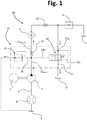
- Figure 1 designated as a whole by M is a machine for the preparation of beverages.
- the machine M is illustrated limitedly to a hydraulic circuit thereof, useful for an understanding of the present invention.
- the hydraulic circuit includes a brewing unit 1, which from the hydraulic standpoint is substantially equivalent to a flow limiter, for delivering a beverage into a cup 2 or the like.
- An electric pump 3 has the inlet connected to a water tank 4 via an intake duct 5 on which a flowmeter 6 can be set, for example of the turbine type, to supply electrical signals (pulses) indicating the flow rate of water drawn in by the pump 3.
- the pump 3 may be a vibration electric pump, or else a pump driven by an electric motor 7 with rotary shaft, of a type in itself known.
- the pressurised water delivered at outlet by the pump 3 reaches an electrical heating device or boiler 9, and from this proceeds towards the brewing unit 1.
- an electrical heating device or boiler 9 Preferentially, provided between the pump 3 and the brewing unit 1 is at least one normally closed unidirectional hydraulic valve, designed to enable a flow of water towards the brewing unit when the pressure of the water coming from the pump exceeds a pre-set threshold value, equal for example to 2 bar.
- a pre-set threshold value equal for example to 2 bar.
- two of such valves are provided, one upstream and the other downstream of the heating device 9, which are designated by 10 and 11, respectively.
- valve 12 Designated by 12 is a discharge valve, the functions of which will be clarified hereinafter.
- the valve 12 is a normally open two-position valve, and operatively associated thereto is a device for self-priming, obtained according to possible embodiments of the invention.
- the valve 12 and the device for self-priming are integrated in a single valve device, such as the one designated by 20.
- valve 12 is a hydraulically driven discharge valve, which comprises:
- the outlet 25 and the main inlet 12 IN constitute respective drives of the valve 12 - designated, respectively, by 25p and 12p in the hydraulic diagram of Figure 1 - one set between the inlet 12 DR-IN and the outlet 12 DR-OUT , upstream of the unidirectional valve 10, and the other set between the inlet 12 IN and the outlet 12 OUT .
- the inlet 12 IN and the outlet 12 OUT are here defined as “main” in so far as they are linked to the main discharge function of the valve 12, in addition to hydraulic driving into the opening condition of a valve member thereof.
- the inlet 12 DR-IN and the outlet 12 DR-OUT are here defined as "auxiliary” in so far as they are basically linked to functions of hydraulic driving into the closing condition of the aforesaid valve member of the valve 12.
- valve 12 or of the device 20 that integrates it, are irrespective of the aims of the invention, and may be obtained, for example, according to the modalities described in the international patent application No. PCT/IB2016/053490 , filed in the name of the present Applicant.
- the arrangement is such that, after the pump 3 is activated for preparation of a beverage, the water forced into the auxiliary inlet 12 DR-IN causes switching of a valve member of the discharge valve 12 from its normally open condition into its closed condition. In this way, the water that leaves the auxiliary outlet 12 DR-OUT of the valve 12 cannot flow out of the main outlet 12 OUT , reaching, instead, only the brewing unit 1.
- the pump 3 is deactivated and, both thanks to the connection 25 to the device for self-priming 22 and thanks to the presence of the aforesaid hydraulic drive for opening 25p and hydraulic drive for closing 12p, the valve 12 returns to its normal opening condition, which enables the water to flow away freely between the main inlet 12 IN and the main outlet 12 OUT , i.e., the water residue present in the part of the circuit comprised between the unidirectional valve 11 and the brewing unit 1 to be discharged, thus enabling evacuation of particulate in suspension that may be present in the water.
- valve 12 or the valve device 20, is illustrated in cross-sectional view, limitedly to the parts of immediate interest for an understanding of the invention, which pertain to the device for self-priming 22.
- 26 is a chamber inside the valve 12, which communicates with the auxiliary inlet 12 DR-IN , with the auxiliary outlet 12 DR-OUT , and with the further outlet 25.
- defined inside the chamber 26 is an end-of-travel detent 26a for a valve member of the valve 12; this valve member is visible in Figure 3 , where it is designated by 26b.
- the device for self-priming 22 comprises a hollow housing structure, having an inlet in fluid communication with the delivery of the pump, and an outlet for enabling spillage of water towards a collecting space, as mentioned previously (such as the tank 4 of Figure 1 ).
- the housing structure of the device 22 is at least in part defined in a single piece with the body of a hydraulic member of the machine M. With reference to the example illustrated, the housing structure then comprises an axially hollow tubular casing 27, defined by the body of the valve 12, with its inlet 22a that corresponds to the outlet 25 of the valve itself.
- the housing structure further comprises a closing element 28, which is coupled to a corresponding end of the casing 27, here the end opposite to the inlet 22a.
- a spillage member designated as a whole by 30.
- the spillage member 30 has a body made of a material that is permeable to water and to air, and is such as to be traversed by water and air at least when the pump 3 of the machine is active.
- the body of the member 30 is a substantially porous body, for example provided with micro-passages designed to enable a modest seepage of water and air between the inlet 22a and the outlet 22b.
- the body of the member 30 is preferentially made of a polymeric material, even of a spongy or cell type.
- the dimensions and/or porosity of the body of the member 30 are chosen so that, in the course of a single operating cycle of the machine aimed at preparing a beverage (indicatively about 30 s of activation of the pump), and with a pump designed to generate a delivery pressure comprised between 2 and 15 bar, the device 22 will enable spillage of an amount of water comprised between 8 and 20 cc, preferably approximately 10 cc.
- seepage of the water is substantially inversely proportional to the pore size and to the length of the body itself.
- the permeable body of the spillage member 30 is mounted in a stationary position within the corresponding casing structure, i.e., in a non-sliding or non-movable way.
- the casing structure may be configured for defining a housing seat for the permeable body, provided with at least one contrast surface for a corresponding longitudinal end of the body itself.
- the casing 27 has an end wall, here made in the body of the valve 12 in which the inlet 22a is defined and which defines a contrast surface, designated by 31a, upon which the inlet end of the body of the member 30 can come to bear.
- the permeable material that forms the body itself may be elastically deformable.
- the permeable body may have dimensions even larger than those of the seat 31 and be inserted therein in a partially compressed condition.
- the body of the member 30 has in any case a cross-sectional dimension or diameter that is larger than the corresponding cross-sectional dimension or diameter of at least one from among the inlet 22a, the outlet 22b, and the seat 31 (or the seat 32, with reference to Figures 6-9 ).
- closing element 28 Also visible in cross-sectional view in Figure 4 is the closing element 28, the inner end face of which in turn defines a contrast surface 28a for the outlet end of the body of the member 30.
- the axial cavity of the casing 27 has a seat 32 for fitting therein a corresponding portion of the closing element 28.
- the closing element 28 has a head, designed to remain on the outside of the casing 27, and a stem, designed to be fitted within the seat 32, which is here defined at the end of the casing 27 opposite to the inlet 22a.
- the seat 32 preferentially has cross-sectional dimensions or a diameter larger than the corresponding cross-sectional dimensions or diameter of the seat 31.
- the stem of the element 28 preferentially has cross-sectional dimensions smaller than those of its head.
- the stem has suitable means for it to be withheld in the seat 32, for example comprising teeth or a surface knurling suitable for enabling it to grip on the inner surface of the seat 32; this measure may, for example, be adopted when the stem is interference fitted into the seat 32b.
- the stem could be provided with a male thread, and the seat 32 with a female thread.
- the body of the spillage member 30 has a substantially cylindrical shape, as highlighted in Figure 5 , but in other embodiments this shape could be different, and also includes shapes that are substantially prismatic or polyhedral (for example, a small block that is substantially cubic or parallelepipedal).
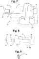
- FIGS 6-9 illustrate the case where the body of the spillage member 30 is substantially disk shaped, as depicted in Figure 9 .
- the portion of cavity that forms the seat 31 of Figure 4 is not occupied by the spillage member 30.
- the body of the spillage member is, instead, housed within a seat 32, designed to receive partially the closing element 28.
- the bottom of the seat 32 defines the contrast surface 32a - as highlighted in Figure 8 - for the inlet end of the body of the member 30.
- the stem of the element 28 is shorter or, conversely, the seat 32 is longer than in the case of Figures 2-5 .
- the casing 27 could also have a length shorter than in the case exemplified, sufficient for definition of just the seat 32, without any need for the seat 31 of Figure 4 .
- the body of the spillage member 30 may be configured like a membrane, possibly also made of a nonwoven fabric, the degree of permeability to air and water of which will enable the purposes of the invention to be achieved.
- the body of the spillage member is obtained from a polymeric porous membrane, for example (but not exclusively) with a base of mixed cellulose esters (MCEs), or else with a base of polyvinylidene fluoride (PVDF), or else with a base of poly ether sulphone (PES).
- MCEs mixed cellulose esters
- PVDF polyvinylidene fluoride
- PES poly ether sulphone
- the polymeric membranes used may have a very small thickness, for example between 100 and 155 ⁇ m, with a pore size preferably of between 0.025 and 8 ⁇ m.
- the spillage member i.e., its permeable body, could also be formed by a layer of porous material (for example, a polymeric material of the type referred to above) deposited on the inner face of the closing element 28 so as to obstruct the outlet 22b.
- the housing structure of a device for self-priming according to the invention is configured as an insert, prearranged for being inserted into a tubular duct or the like belonging to a hydraulic member of the machine for the preparation of beverages.
- Embodiments of this sort are exemplified in Figures 10 and 11 .
- Figure 10 exemplifies the case of a valve of the machine according to the invention (here assumed as being a valve of the type previously designated by 12) that has, at its outlet 25, a tubular connector 29, inserted in which is the device 22.
- the housing structure comprises a body or insert 27' prearranged for being inserted into the axial cavity 29a of the connector 29.
- the body or insert 27' is substantially cylindrical and interference fitted into the cavity 29a.
- the insert 27' defines a seat 31 for the body of the permeable element 30, with said seat that opens at the distal end of the insert itself, in order to enable insertion therein of the body of the spillage member 30 and thus form the inlet 22a.
- the permeable body has a diameter or cross-sectional dimension larger than that of the outlet 25 of the valve 12: in this way, the body of the valve 12 - in its part that surrounds the outlet 25 - defines a contrast surface both for the insert 27' and for the permeable body contained therein.
- the insert 27' has a transverse wall 28', which forms the contrast surface for the outlet end of the body of the permeable member 30.
- a passage or hole that forms the outlet 22b of the self-priming device 22.
- Figure 10 illustrates the case of a body of the spillage member having a substantially cylindrical elongated shape.
- the same concepts as those described with reference to Figure 10 may on the other hand be applied also to the case of a disk-shaped permeable body, as exemplified in Figure 11 , where the same reference numbers of Figure 10 are used to designate elements that are technically equivalent to the ones already described above.
- the permeable body may be obtained by a membrane, for example of the type referred to above.
- the spillage member may conveniently comprise a support or frame for the membrane, for example a peripheral frame in order to facilitate mounting thereof in position.
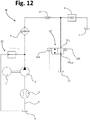
- the device for self-priming provided according to the invention may of course be connected in various points of the hydraulic circuit of a machine for the preparation of beverages, in particular downstream of the pump, even not directly associated to or integrated in a hydraulic component of the machine.
- the self-priming device comprises a casing body of its own, which is configured for fluid connection to a different element of the hydraulic circuit of the machine.
- a casing body of its own which is configured for fluid connection to a different element of the hydraulic circuit of the machine.
- the device for self-priming 22 is connected in fluid communication to the delivery of the pump 3, upstream of the heating device 9, and in isolation from other components (in the case of Figure 12 , the unidirectional valve 10 is omitted and the hydraulically driven valve 12 of Figure 1 is replaced by a simple normally open electromagnetic valve 12', the valve member of which is driven into the closing condition by a solenoid 12a, countering the action of a spring 12b).
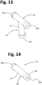
- the housing structure of the device 22 may belong to a connector, in particular of the T type, as illustrated in Figure 13 , where the same reference numbers as those of the previous figures are used to designate elements that are technically equivalent to the ones already described above.
- the body of the connector - designated as a whole by 23 - defines in a single piece, in addition to the tubular part 27 for housing the spillage member, also an inlet 23a for fluid connection towards the delivery of the pump 3, and an outlet 23c for fluid connection towards the heating device 9.
- the inlet 23a and the outlet 23b may, for example, be connected to respective flexible tubes.
- the housing structure of the device 22 may advantageously include a closing element 28 defining the outlet of the device for self-priming 22 (here not visible).
- Figure 14 illustrates a further possible embodiment of the body 23 of a device for self-priming 22, which comprises a substantially tubular part 27.
- the tubular part 27 is provided with an end 23d defining the inlet (22a) of the self-priming device 22 and configured for fluid connection, for example, to a tube connected in the hydraulic circuit downstream of the pump (for instance, to a connector of the type designated by 29 in Figure 10 ), and, at the other end, with an outlet 22b, for example defined by a closing element of the type already designated by 28.
- the end 23d could be constituted by an element of the type designated by 28.
- the device for self-priming 22 guarantees - via elimination or at least reduction of the presence of air in the circuit downstream of the pump - the presence of pressurised water in the circuit, when the pump is active, also with the brewing unit containing the dose of precursor (for example in the form of a capsule) closed.
- the amount of water that traverses the permeable body of the spillage member 30 is modest and, since it is clean water, may be conveniently made to flow towards the tank of the machine. Interruption of operation of the pump brings the hydraulic circuit of the machine back to ambient pressure, and in this condition spillage of water by the device 22 is interrupted.
- the pressure generated by activation of the pump 3 in a driving chamber brings about closing of a valve member (such as the one designated previously by 26b), which interrupts the fluid connection between the main inlet 12 IN and the outlet 12 OUT , as mentioned previously.
- a valve member such as the one designated previously by 26b
- the self-priming device 22 guarantees the necessary drop in pressure in the aforesaid driving chamber 26, with consequent return of the valve member 26b into the condition of opening of the passageway between the main inlet 12 IN and the outlet 12 OUT (see, for example, what is described in the international patent application No. PCT/IB2016/053490 referred to above).
- the device for self-priming provided according to the invention is simple and economically advantageous to produce, as well as of reliable operation, in so far as it is not affected by the wear typical of the prior art.
- the self-priming device described is, if need be, easily integrated in other hydraulic elements of the machine for the preparation of beverages (for example, in a valve or other valve device), and works efficiently, not only in combination with vibration pumps, but also in combination with pumps with non-impulsive operation, i.e., with constant delivery, such as the one designated by 3.
- a permeable spillage member of the type described is able to perform effectively its own functions irrespective of the delivery of the pump.
- the material permeable to water and air designed to provide the bleeder member could be injected in the production stage in the corresponding casing structure, and then perform the functions described following upon its solidification or polymerisation.
Landscapes
- Engineering & Computer Science (AREA)
- Food Science & Technology (AREA)
- Mechanical Engineering (AREA)
- Structures Of Non-Positive Displacement Pumps (AREA)
- Apparatus For Making Beverages (AREA)
- Tea And Coffee (AREA)
- Details Of Reciprocating Pumps (AREA)
- Devices For Dispensing Beverages (AREA)
Claims (14)
- Vorrichtung zur Selbstansaugung einer Maschine (M) zur Herstellung von Getränken, wobei die Vorrichtung Folgendes umfasst:eine hohle Gehäusestruktur (23; 27, 28; 27') mit einem Einlass (22a), der dazu ausgestaltet ist, mit dem Auslass oder Ausstoß einer Pumpe (3) der Maschine in Fluidkommunikation verbunden zu sein, und einem Auslass (22b) für Auslauf von Wasser zu einem Sammelraum (4); undein Auslaufelement (30), das zwischen dem Einlass (22a) und dem Auslass (22b) der Gehäusestruktur (23; 27, 28; 27') aufgestellt ist,wobei die Vorrichtung dadurch gekennzeichnet ist, dass das Auslaufelement (30) einen Körper aufweist, der mit einem Material ausgebildet ist, das wasser- und luftdurchlässig ist, wobei der Körper dazu vorbereitet ist, von Wasser und möglicher Luft, die von der Pumpe (3) der Maschine druckbeaufschlagt wird, durchquert zu werden.
- Vorrichtung nach Anspruch 1, wobei der Körper des Auslaufelements (30) ein im Wesentlichen poröser Körper ist.
- Vorrichtung nach Anspruch 1 oder 2, wobei der Körper des Auslaufelements (30) in einer ortsfesten Position innerhalb der Gehäusestruktur (23; 27, 28; 27') aufgestellt ist.
- Vorrichtung nach einem der Ansprüche 1-3, wobei die Gehäusestruktur (23; 27, 28; 27') einen Positionierungssitz (31; 32) für den Körper des Auslaufelements (30) aufweist, der vorzugsweise eine Anschlagoberfläche (31a; 32a) definiert für mindestens ein Längsende oder Fläche des Körpers des Auslaufelements (30).
- Vorrichtung nach einem der Ansprüche 1-4, wobei die Gehäusestruktur (23; 27, 28) einen axial hohlen Rohrkörper (27), innerhalb dessen der Körper des Auslaufelements (30) untergebracht ist, und mindestens ein Schließteil (23d; 28), das an einem entsprechenden Ende des Rohrkörpers (27) gekoppelt ist, umfasst, wobei das mindestens eine Schließteil (23d; 28) einen aus dem Einlass (22a) und dem Auslass (22b) der Gehäusestruktur (23; 27, 28) definiert.
- Vorrichtung nach Anspruch 5, wobei das mindestens eine Schließteil (23d; 28) eine Anschlagoberfläche (28a) definiert für ein Längsende oder Fläche des Körpers des Auslaufelements (30).
- Vorrichtung nach einem der Ansprüche 4-6, wobei der Körper des Auslaufelements (30) eine Querschnittsabmessung oder einen Durchmesser aufweist, die/der größer ist als eine/ein entsprechende/-r Querschnittsabmessung oder Durchmesser von mindestens einem aus dem Einlass (22a), dem Auslass (22b) und dem Positionierungssitz (31: 32) der Gehäusestruktur (23; 27, 28; 27').
- Vorrichtung nach einem der Ansprüche 1-7, wobei die Gehäusestruktur (27, 28) mindestens teilweise einstückig mit dem Körper eines hydraulischen Elements (12) der Maschine (M), wie einer Ventilvorrichtung, definiert ist.
- Vorrichtung nach einem der Ansprüche 1-7, wobei die Gehäusestruktur (27') als Einlage ausgestaltet ist, die zum Einlegen in einen Rohrkanal (29), der zu einem hydraulischen Element (12) der Maschine (M) zur Herstellung von Getränken gehört, vorbereitet ist.
- Vorrichtung nach einem der Ansprüche 1-7, wobei die Gehäusestruktur einen eignen Hüllkörper (23) umfasst, der zur Fluidverbindung mit einem Körper eines anderen Teils der hydraulischen Schaltung der Maschine (M) zur Herstellung von Getränken ausgestaltet ist, wobei der Hüllkörper (23) beispielsweise zur Fluidverbindung mit einem Schlauch ausgestaltet ist oder sonst im Wesentlichen als T-Verbinder ausgestaltet ist.
- Vorrichtung nach einem der Ansprüche 1-10, wobei der Körper des Auslaufelements (30) zylinderförmig oder sonst scheibenartig oder sonst membranartig oder sonst polyedrisch ausgebildet ist.
- Vorrichtung nach einem der Ansprüche 1-11, wobei der Körper des Auslaufelements (30) mit einem polymerischen Material ausgebildet ist.
- Integrierte Ventilvorrichtung (20) einer Maschine zur Herstellung von Getränken (M), umfassen eine Vorrichtung zur Selbstansaugung (22) nach einem der Ansprüche 1-12.
- Maschine (M) zur Herstellung von Getränken, insbesondere Espresso, umfassend eine hydraulische Schaltung, die Folgendes enthält:- eine Brüheinheit (1);- einen Wassertank (4);- eine Pumpe (3), deren Einlass in Fluidkommunikation mit dem Wassertank (4) verbunden ist und deren Auslass oder Ausstoß in Fluidkommunikation mit der Brüheinheit (1) verbunden ist;- eine Heizvorrichtung (9) zum Erhitzen von Wasser, das von der Pumpe (3) zu der Brüheinheit (1) hin zu leiten;- eine Vorrichtung zur Selbstansaugung (22) nach einem der Ansprüche 1-12,
wobei die hohle Gehäusestruktur (23; 27, 28; 27') der Vorrichtung zur Selbstansaugung (22) den Einlass (22a) derselben in Fluidverbindung mit dem Auslass oder Ausstoß der Pumpe (3) und den Auslass (22b) derselben in Fluidverbindung mit einem Sammelraum, insbesondere dem Wassertank (4), aufweist;
wobei das Auslaufelement (30) der Vorrichtung zur Selbstansaugung (22) zwischen dem Einlass (22a) und dem Auslass (22b) der hohlen Gehäusestruktur (23; 27, 28; 27') aufgestellt ist,
und wobei der Körper des Auslaufelements (30), der mit dem Material ausgebildet ist, das wasser- und luftdurchlässig ist, dazu geeignet ist, von Wasser und Luft durchquert zu werden, wenn die Pumpe (3) aktiv ist.
Applications Claiming Priority (2)
| Application Number | Priority Date | Filing Date | Title |
|---|---|---|---|
| IT102016000083066A IT201600083066A1 (it) | 2016-08-05 | 2016-08-05 | Macchina per la preparazione di bevande, in particolare caffe' espresso, e dispositivo di auto-innesco utilizzabile in una tale macchina |
| PCT/IB2017/054600 WO2018025134A1 (en) | 2016-08-05 | 2017-07-28 | A machine for the preparation of beverages, in particular espresso coffee, and device for self-priming which can be used in said machine |
Publications (2)
| Publication Number | Publication Date |
|---|---|
| EP3493720A1 EP3493720A1 (de) | 2019-06-12 |
| EP3493720B1 true EP3493720B1 (de) | 2020-08-19 |
Family
ID=57906857
Family Applications (1)
| Application Number | Title | Priority Date | Filing Date |
|---|---|---|---|
| EP17758951.2A Active EP3493720B1 (de) | 2016-08-05 | 2017-07-28 | Maschine zur herstellung von getränken, insbesondere espresso, und vorrichtung zur selbstansaugung, die in der besagtem maschine verwendet werden kann |
Country Status (7)
| Country | Link |
|---|---|
| US (1) | US11445851B2 (de) |
| EP (1) | EP3493720B1 (de) |
| CN (1) | CN109640758B (de) |
| AU (1) | AU2017307366B2 (de) |
| IT (1) | IT201600083066A1 (de) |
| MX (1) | MX2019001107A (de) |
| WO (1) | WO2018025134A1 (de) |
Families Citing this family (2)
| Publication number | Priority date | Publication date | Assignee | Title |
|---|---|---|---|---|
| CN111637365B (zh) * | 2019-09-29 | 2024-12-06 | 上海爱餐机器人(集团)有限公司 | 水阀集成组件、一体式分路集成水泵、水路系统及炒菜机 |
| US20240286882A1 (en) * | 2023-02-23 | 2024-08-29 | Crystal Mountain International Limited | Method for hands free auto-filling one or more water reservoirs of a liquid dispenser and a related apparatus |
Family Cites Families (17)
| Publication number | Priority date | Publication date | Assignee | Title |
|---|---|---|---|---|
| US3586040A (en) * | 1969-11-06 | 1971-06-22 | Machinery Co Const | Valve means |
| US4852621A (en) * | 1987-08-10 | 1989-08-01 | Bear Don E | Bottled water pressurization system |
| IT233538Y1 (it) * | 1994-07-01 | 2000-01-28 | Miralfin Srl | Dispositivo valvolare per l'autoinnesco di una pompa particolarmente per macchine per la produzione di un infuso di caffe' |
| US5911562A (en) * | 1996-07-29 | 1999-06-15 | Hypro Corporation | High pressure fluid delivery system with automatic priming valve |
| NL1029155C2 (nl) * | 2004-10-19 | 2006-04-20 | Sara Lee De Nv | Systeem en werkwijze voor het bereiden van een voor consumptie geschikte drank. |
| ITFI20050169A1 (it) * | 2005-07-27 | 2007-01-28 | Saeco Ipr Ltd | Circuito idraulico per macchine da bevande espresso, valvola di scarico e sicurezza per detto circuito e relativo metodo per produzione di bevande espresso |
| DE602005015737D1 (de) * | 2005-12-16 | 2009-09-10 | Nestec Sa | Ansaugventil eines Wasserkreislaufs einer Getränkemaschine |
| DE102007058375A1 (de) * | 2007-12-05 | 2009-06-10 | BSH Bosch und Siemens Hausgeräte GmbH | Getränkemaschine mit einem Mehrfunktionenventil |
| WO2010021532A1 (en) * | 2008-08-19 | 2010-02-25 | Sadeli Rezeki | Beverage dispenser |
| EP2612579A1 (de) * | 2012-01-05 | 2013-07-10 | Nestec S.A. | Getränkezubereitungsmaschine |
| CN102920335B (zh) * | 2012-11-05 | 2014-10-22 | 沁园集团股份有限公司 | 一种全自动即热冲泡机 |
| CN103799880A (zh) * | 2012-11-08 | 2014-05-21 | 伊莱克斯(中国)电器有限公司 | 咖啡机中的水箱连接件 |
| CN105813511B (zh) * | 2013-12-20 | 2019-01-15 | 雀巢产品技术援助有限公司 | 饮料制备组件 |
| CN104161463B (zh) * | 2014-02-25 | 2017-04-26 | 周林斌 | 电压力锅进水和出水的冲泡机器及其方法 |
| KR101553517B1 (ko) * | 2014-07-25 | 2015-09-16 | 주식회사 테라 | 소음 및 진동 발생이 억제되는 커피머신용 진동펌프 |
| CN106998953B (zh) * | 2014-12-02 | 2020-05-05 | 路易吉拉瓦扎股份公司 | 用于制备饮料,尤其是浓缩咖啡的机器 |
| CN204654642U (zh) * | 2015-05-11 | 2015-09-23 | 浙江酷菲尔电器有限公司 | 一种饮品酿造机器的酿造室及排气装置 |
-
2016
- 2016-08-05 IT IT102016000083066A patent/IT201600083066A1/it unknown
-
2017
- 2017-07-28 MX MX2019001107A patent/MX2019001107A/es unknown
- 2017-07-28 CN CN201780040247.8A patent/CN109640758B/zh active Active
- 2017-07-28 US US16/322,243 patent/US11445851B2/en active Active
- 2017-07-28 WO PCT/IB2017/054600 patent/WO2018025134A1/en not_active Ceased
- 2017-07-28 AU AU2017307366A patent/AU2017307366B2/en active Active
- 2017-07-28 EP EP17758951.2A patent/EP3493720B1/de active Active
Non-Patent Citations (1)
| Title |
|---|
| None * |
Also Published As
| Publication number | Publication date |
|---|---|
| AU2017307366A1 (en) | 2018-12-20 |
| IT201600083066A1 (it) | 2018-02-05 |
| MX2019001107A (es) | 2019-10-07 |
| CA3025752A1 (en) | 2018-02-08 |
| US20190191920A1 (en) | 2019-06-27 |
| CN109640758B (zh) | 2021-06-22 |
| EP3493720A1 (de) | 2019-06-12 |
| AU2017307366B2 (en) | 2022-12-08 |
| US11445851B2 (en) | 2022-09-20 |
| WO2018025134A1 (en) | 2018-02-08 |
| CN109640758A (zh) | 2019-04-16 |
Similar Documents
| Publication | Publication Date | Title |
|---|---|---|
| US11122929B2 (en) | Machine for preparing beverages, in particular espresso coffee, a valve and a valve unit that can be used in said machine | |
| EP3310222B1 (de) | Maschine zur zubereitung von getränken, insbesondere espresso, sowie darin verwendbares ventil und ventilanordnung | |
| CA2647362C (en) | Mems device and method for delivery of therapeutic agents | |
| EP3579730B1 (de) | Membranpumpe für getränkezubereitungsmodul | |
| US8870025B2 (en) | Method and device for aseptically dispensing multiple portions of a fluid | |
| US20140079580A1 (en) | Pump Unit For Water Jet Surgery | |
| US11445851B2 (en) | Machine for the preparation of beverages, in particular espresso coffee, and device for self-priming which can be used in said machine | |
| EP2904295B1 (de) | Rückschlagventil, einspritzanordnung und getränkeherstellungsmaschine | |
| US20130105521A1 (en) | Method and device for aseptically dispensing multiple portions of a fluid | |
| JP2009519067A (ja) | 飲料用機械のウォータ回路のためのプライミングバルブ装置 | |
| CA3025752C (en) | A machine for the preparation of beverages, in particular espresso coffee, and device for self-priming which can be used in said machine | |
| CN112460000B (zh) | 一种泵及液体输送设备 | |
| US20230389747A1 (en) | Machine for Preparing Coffee Beverages | |
| CN224085554U (zh) | 洗耳器 | |
| JPH0683968U (ja) | 液体噴射装置のアンローダ |
Legal Events
| Date | Code | Title | Description |
|---|---|---|---|
| STAA | Information on the status of an ep patent application or granted ep patent |
Free format text: STATUS: UNKNOWN |
|
| STAA | Information on the status of an ep patent application or granted ep patent |
Free format text: STATUS: THE INTERNATIONAL PUBLICATION HAS BEEN MADE |
|
| PUAI | Public reference made under article 153(3) epc to a published international application that has entered the european phase |
Free format text: ORIGINAL CODE: 0009012 |
|
| STAA | Information on the status of an ep patent application or granted ep patent |
Free format text: STATUS: REQUEST FOR EXAMINATION WAS MADE |
|
| 17P | Request for examination filed |
Effective date: 20181127 |
|
| AK | Designated contracting states |
Kind code of ref document: A1 Designated state(s): AL AT BE BG CH CY CZ DE DK EE ES FI FR GB GR HR HU IE IS IT LI LT LU LV MC MK MT NL NO PL PT RO RS SE SI SK SM TR |
|
| AX | Request for extension of the european patent |
Extension state: BA ME |
|
| DAV | Request for validation of the european patent (deleted) | ||
| DAX | Request for extension of the european patent (deleted) | ||
| GRAP | Despatch of communication of intention to grant a patent |
Free format text: ORIGINAL CODE: EPIDOSNIGR1 |
|
| STAA | Information on the status of an ep patent application or granted ep patent |
Free format text: STATUS: GRANT OF PATENT IS INTENDED |
|
| INTG | Intention to grant announced |
Effective date: 20200506 |
|
| RIN1 | Information on inventor provided before grant (corrected) |
Inventor name: PICONE, GABRIELE Inventor name: ROTTA, DENIS Inventor name: COLONNA, ANDREA |
|
| GRAS | Grant fee paid |
Free format text: ORIGINAL CODE: EPIDOSNIGR3 |
|
| GRAA | (expected) grant |
Free format text: ORIGINAL CODE: 0009210 |
|
| STAA | Information on the status of an ep patent application or granted ep patent |
Free format text: STATUS: THE PATENT HAS BEEN GRANTED |
|
| AK | Designated contracting states |
Kind code of ref document: B1 Designated state(s): AL AT BE BG CH CY CZ DE DK EE ES FI FR GB GR HR HU IE IS IT LI LT LU LV MC MK MT NL NO PL PT RO RS SE SI SK SM TR |
|
| REG | Reference to a national code |
Ref country code: CH Ref legal event code: EP |
|
| REG | Reference to a national code |
Ref country code: DE Ref legal event code: R096 Ref document number: 602017022035 Country of ref document: DE |
|
| REG | Reference to a national code |
Ref country code: AT Ref legal event code: REF Ref document number: 1302978 Country of ref document: AT Kind code of ref document: T Effective date: 20200915 |
|
| REG | Reference to a national code |
Ref country code: IE Ref legal event code: FG4D |
|
| REG | Reference to a national code |
Ref country code: LT Ref legal event code: MG4D |
|
| REG | Reference to a national code |
Ref country code: NL Ref legal event code: MP Effective date: 20200819 |
|
| PG25 | Lapsed in a contracting state [announced via postgrant information from national office to epo] |
Ref country code: GR Free format text: LAPSE BECAUSE OF FAILURE TO SUBMIT A TRANSLATION OF THE DESCRIPTION OR TO PAY THE FEE WITHIN THE PRESCRIBED TIME-LIMIT Effective date: 20201120 Ref country code: HR Free format text: LAPSE BECAUSE OF FAILURE TO SUBMIT A TRANSLATION OF THE DESCRIPTION OR TO PAY THE FEE WITHIN THE PRESCRIBED TIME-LIMIT Effective date: 20200819 Ref country code: LT Free format text: LAPSE BECAUSE OF FAILURE TO SUBMIT A TRANSLATION OF THE DESCRIPTION OR TO PAY THE FEE WITHIN THE PRESCRIBED TIME-LIMIT Effective date: 20200819 Ref country code: SE Free format text: LAPSE BECAUSE OF FAILURE TO SUBMIT A TRANSLATION OF THE DESCRIPTION OR TO PAY THE FEE WITHIN THE PRESCRIBED TIME-LIMIT Effective date: 20200819 Ref country code: BG Free format text: LAPSE BECAUSE OF FAILURE TO SUBMIT A TRANSLATION OF THE DESCRIPTION OR TO PAY THE FEE WITHIN THE PRESCRIBED TIME-LIMIT Effective date: 20201119 Ref country code: FI Free format text: LAPSE BECAUSE OF FAILURE TO SUBMIT A TRANSLATION OF THE DESCRIPTION OR TO PAY THE FEE WITHIN THE PRESCRIBED TIME-LIMIT Effective date: 20200819 Ref country code: NO Free format text: LAPSE BECAUSE OF FAILURE TO SUBMIT A TRANSLATION OF THE DESCRIPTION OR TO PAY THE FEE WITHIN THE PRESCRIBED TIME-LIMIT Effective date: 20201119 Ref country code: PT Free format text: LAPSE BECAUSE OF FAILURE TO SUBMIT A TRANSLATION OF THE DESCRIPTION OR TO PAY THE FEE WITHIN THE PRESCRIBED TIME-LIMIT Effective date: 20201221 |
|
| REG | Reference to a national code |
Ref country code: AT Ref legal event code: MK05 Ref document number: 1302978 Country of ref document: AT Kind code of ref document: T Effective date: 20200819 |
|
| PG25 | Lapsed in a contracting state [announced via postgrant information from national office to epo] |
Ref country code: NL Free format text: LAPSE BECAUSE OF FAILURE TO SUBMIT A TRANSLATION OF THE DESCRIPTION OR TO PAY THE FEE WITHIN THE PRESCRIBED TIME-LIMIT Effective date: 20200819 Ref country code: LV Free format text: LAPSE BECAUSE OF FAILURE TO SUBMIT A TRANSLATION OF THE DESCRIPTION OR TO PAY THE FEE WITHIN THE PRESCRIBED TIME-LIMIT Effective date: 20200819 Ref country code: RS Free format text: LAPSE BECAUSE OF FAILURE TO SUBMIT A TRANSLATION OF THE DESCRIPTION OR TO PAY THE FEE WITHIN THE PRESCRIBED TIME-LIMIT Effective date: 20200819 Ref country code: PL Free format text: LAPSE BECAUSE OF FAILURE TO SUBMIT A TRANSLATION OF THE DESCRIPTION OR TO PAY THE FEE WITHIN THE PRESCRIBED TIME-LIMIT Effective date: 20200819 Ref country code: IS Free format text: LAPSE BECAUSE OF FAILURE TO SUBMIT A TRANSLATION OF THE DESCRIPTION OR TO PAY THE FEE WITHIN THE PRESCRIBED TIME-LIMIT Effective date: 20201219 |
|
| PG25 | Lapsed in a contracting state [announced via postgrant information from national office to epo] |
Ref country code: SM Free format text: LAPSE BECAUSE OF FAILURE TO SUBMIT A TRANSLATION OF THE DESCRIPTION OR TO PAY THE FEE WITHIN THE PRESCRIBED TIME-LIMIT Effective date: 20200819 Ref country code: EE Free format text: LAPSE BECAUSE OF FAILURE TO SUBMIT A TRANSLATION OF THE DESCRIPTION OR TO PAY THE FEE WITHIN THE PRESCRIBED TIME-LIMIT Effective date: 20200819 Ref country code: RO Free format text: LAPSE BECAUSE OF FAILURE TO SUBMIT A TRANSLATION OF THE DESCRIPTION OR TO PAY THE FEE WITHIN THE PRESCRIBED TIME-LIMIT Effective date: 20200819 Ref country code: CZ Free format text: LAPSE BECAUSE OF FAILURE TO SUBMIT A TRANSLATION OF THE DESCRIPTION OR TO PAY THE FEE WITHIN THE PRESCRIBED TIME-LIMIT Effective date: 20200819 Ref country code: DK Free format text: LAPSE BECAUSE OF FAILURE TO SUBMIT A TRANSLATION OF THE DESCRIPTION OR TO PAY THE FEE WITHIN THE PRESCRIBED TIME-LIMIT Effective date: 20200819 |
|
| REG | Reference to a national code |
Ref country code: DE Ref legal event code: R097 Ref document number: 602017022035 Country of ref document: DE |
|
| PG25 | Lapsed in a contracting state [announced via postgrant information from national office to epo] |
Ref country code: ES Free format text: LAPSE BECAUSE OF FAILURE TO SUBMIT A TRANSLATION OF THE DESCRIPTION OR TO PAY THE FEE WITHIN THE PRESCRIBED TIME-LIMIT Effective date: 20200819 Ref country code: AL Free format text: LAPSE BECAUSE OF FAILURE TO SUBMIT A TRANSLATION OF THE DESCRIPTION OR TO PAY THE FEE WITHIN THE PRESCRIBED TIME-LIMIT Effective date: 20200819 Ref country code: AT Free format text: LAPSE BECAUSE OF FAILURE TO SUBMIT A TRANSLATION OF THE DESCRIPTION OR TO PAY THE FEE WITHIN THE PRESCRIBED TIME-LIMIT Effective date: 20200819 |
|
| PLBE | No opposition filed within time limit |
Free format text: ORIGINAL CODE: 0009261 |
|
| STAA | Information on the status of an ep patent application or granted ep patent |
Free format text: STATUS: NO OPPOSITION FILED WITHIN TIME LIMIT |
|
| PG25 | Lapsed in a contracting state [announced via postgrant information from national office to epo] |
Ref country code: SK Free format text: LAPSE BECAUSE OF FAILURE TO SUBMIT A TRANSLATION OF THE DESCRIPTION OR TO PAY THE FEE WITHIN THE PRESCRIBED TIME-LIMIT Effective date: 20200819 |
|
| 26N | No opposition filed |
Effective date: 20210520 |
|
| PG25 | Lapsed in a contracting state [announced via postgrant information from national office to epo] |
Ref country code: SI Free format text: LAPSE BECAUSE OF FAILURE TO SUBMIT A TRANSLATION OF THE DESCRIPTION OR TO PAY THE FEE WITHIN THE PRESCRIBED TIME-LIMIT Effective date: 20200819 |
|
| REG | Reference to a national code |
Ref country code: CH Ref legal event code: PL |
|
| PG25 | Lapsed in a contracting state [announced via postgrant information from national office to epo] |
Ref country code: MC Free format text: LAPSE BECAUSE OF FAILURE TO SUBMIT A TRANSLATION OF THE DESCRIPTION OR TO PAY THE FEE WITHIN THE PRESCRIBED TIME-LIMIT Effective date: 20200819 |
|
| REG | Reference to a national code |
Ref country code: BE Ref legal event code: MM Effective date: 20210731 |
|
| PG25 | Lapsed in a contracting state [announced via postgrant information from national office to epo] |
Ref country code: LI Free format text: LAPSE BECAUSE OF NON-PAYMENT OF DUE FEES Effective date: 20210731 Ref country code: CH Free format text: LAPSE BECAUSE OF NON-PAYMENT OF DUE FEES Effective date: 20210731 |
|
| PG25 | Lapsed in a contracting state [announced via postgrant information from national office to epo] |
Ref country code: LU Free format text: LAPSE BECAUSE OF NON-PAYMENT OF DUE FEES Effective date: 20210728 |
|
| PG25 | Lapsed in a contracting state [announced via postgrant information from national office to epo] |
Ref country code: IE Free format text: LAPSE BECAUSE OF NON-PAYMENT OF DUE FEES Effective date: 20210728 Ref country code: BE Free format text: LAPSE BECAUSE OF NON-PAYMENT OF DUE FEES Effective date: 20210731 |
|
| PG25 | Lapsed in a contracting state [announced via postgrant information from national office to epo] |
Ref country code: CY Free format text: LAPSE BECAUSE OF FAILURE TO SUBMIT A TRANSLATION OF THE DESCRIPTION OR TO PAY THE FEE WITHIN THE PRESCRIBED TIME-LIMIT Effective date: 20200819 |
|
| P01 | Opt-out of the competence of the unified patent court (upc) registered |
Effective date: 20230529 |
|
| PG25 | Lapsed in a contracting state [announced via postgrant information from national office to epo] |
Ref country code: HU Free format text: LAPSE BECAUSE OF FAILURE TO SUBMIT A TRANSLATION OF THE DESCRIPTION OR TO PAY THE FEE WITHIN THE PRESCRIBED TIME-LIMIT; INVALID AB INITIO Effective date: 20170728 |
|
| PG25 | Lapsed in a contracting state [announced via postgrant information from national office to epo] |
Ref country code: MK Free format text: LAPSE BECAUSE OF FAILURE TO SUBMIT A TRANSLATION OF THE DESCRIPTION OR TO PAY THE FEE WITHIN THE PRESCRIBED TIME-LIMIT Effective date: 20200819 |
|
| PG25 | Lapsed in a contracting state [announced via postgrant information from national office to epo] |
Ref country code: TR Free format text: LAPSE BECAUSE OF FAILURE TO SUBMIT A TRANSLATION OF THE DESCRIPTION OR TO PAY THE FEE WITHIN THE PRESCRIBED TIME-LIMIT Effective date: 20200819 |
|
| PG25 | Lapsed in a contracting state [announced via postgrant information from national office to epo] |
Ref country code: MT Free format text: LAPSE BECAUSE OF FAILURE TO SUBMIT A TRANSLATION OF THE DESCRIPTION OR TO PAY THE FEE WITHIN THE PRESCRIBED TIME-LIMIT Effective date: 20200819 |
|
| PGFP | Annual fee paid to national office [announced via postgrant information from national office to epo] |
Ref country code: DE Payment date: 20250722 Year of fee payment: 9 |
|
| PGFP | Annual fee paid to national office [announced via postgrant information from national office to epo] |
Ref country code: IT Payment date: 20250731 Year of fee payment: 9 |
|
| PGFP | Annual fee paid to national office [announced via postgrant information from national office to epo] |
Ref country code: GB Payment date: 20250724 Year of fee payment: 9 |
|
| PGFP | Annual fee paid to national office [announced via postgrant information from national office to epo] |
Ref country code: FR Payment date: 20250723 Year of fee payment: 9 |