EP3493371A1 - Reinforced cage rotor - Google Patents
Reinforced cage rotor Download PDFInfo
- Publication number
- EP3493371A1 EP3493371A1 EP17204676.5A EP17204676A EP3493371A1 EP 3493371 A1 EP3493371 A1 EP 3493371A1 EP 17204676 A EP17204676 A EP 17204676A EP 3493371 A1 EP3493371 A1 EP 3493371A1
- Authority
- EP
- European Patent Office
- Prior art keywords
- honeycomb
- rotor
- short
- strength
- circuit ring
- Prior art date
- Legal status (The legal status is an assumption and is not a legal conclusion. Google has not performed a legal analysis and makes no representation as to the accuracy of the status listed.)
- Withdrawn
Links
- 238000000034 method Methods 0.000 claims abstract description 41
- 239000000463 material Substances 0.000 claims abstract description 29
- 238000004519 manufacturing process Methods 0.000 claims abstract description 27
- 239000000654 additive Substances 0.000 claims abstract description 17
- 230000000996 additive effect Effects 0.000 claims abstract description 17
- RYGMFSIKBFXOCR-UHFFFAOYSA-N Copper Chemical compound [Cu] RYGMFSIKBFXOCR-UHFFFAOYSA-N 0.000 claims description 16
- 239000000956 alloy Substances 0.000 claims description 16
- 229910045601 alloy Inorganic materials 0.000 claims description 16
- 239000010949 copper Substances 0.000 claims description 16
- 229910052802 copper Inorganic materials 0.000 claims description 16
- 229910000831 Steel Inorganic materials 0.000 claims description 10
- 229910052782 aluminium Inorganic materials 0.000 claims description 10
- XAGFODPZIPBFFR-UHFFFAOYSA-N aluminium Chemical compound [Al] XAGFODPZIPBFFR-UHFFFAOYSA-N 0.000 claims description 10
- 239000010959 steel Substances 0.000 claims description 10
- 239000000843 powder Substances 0.000 claims description 9
- 230000002787 reinforcement Effects 0.000 claims description 7
- RTAQQCXQSZGOHL-UHFFFAOYSA-N Titanium Chemical compound [Ti] RTAQQCXQSZGOHL-UHFFFAOYSA-N 0.000 claims description 6
- 239000010936 titanium Substances 0.000 claims description 6
- 229910052719 titanium Inorganic materials 0.000 claims description 6
- 238000003466 welding Methods 0.000 claims description 6
- 229910052751 metal Inorganic materials 0.000 claims description 3
- 239000002184 metal Substances 0.000 claims description 3
- 230000005611 electricity Effects 0.000 claims description 2
- 241000264877 Hippospongia communis Species 0.000 description 70
- 239000002245 particle Substances 0.000 description 7
- 241000555745 Sciuridae Species 0.000 description 6
- 230000002093 peripheral effect Effects 0.000 description 5
- 239000011324 bead Substances 0.000 description 2
- 238000001465 metallisation Methods 0.000 description 2
- 230000015572 biosynthetic process Effects 0.000 description 1
- 238000005520 cutting process Methods 0.000 description 1
- 230000001419 dependent effect Effects 0.000 description 1
- 238000009826 distribution Methods 0.000 description 1
- 239000003381 stabilizer Substances 0.000 description 1
- 239000007858 starting material Substances 0.000 description 1
- 239000000758 substrate Substances 0.000 description 1
- XLYOFNOQVPJJNP-UHFFFAOYSA-N water Chemical compound O XLYOFNOQVPJJNP-UHFFFAOYSA-N 0.000 description 1
Images


Classifications
-
- H—ELECTRICITY
- H02—GENERATION; CONVERSION OR DISTRIBUTION OF ELECTRIC POWER
- H02K—DYNAMO-ELECTRIC MACHINES
- H02K15/00—Methods or apparatus specially adapted for manufacturing, assembling, maintaining or repairing of dynamo-electric machines
- H02K15/0012—Manufacturing cage rotors
-
- H—ELECTRICITY
- H02—GENERATION; CONVERSION OR DISTRIBUTION OF ELECTRIC POWER
- H02K—DYNAMO-ELECTRIC MACHINES
- H02K17/00—Asynchronous induction motors; Asynchronous induction generators
- H02K17/02—Asynchronous induction motors
- H02K17/16—Asynchronous induction motors having rotors with internally short-circuited windings, e.g. cage rotors
- H02K17/168—Asynchronous induction motors having rotors with internally short-circuited windings, e.g. cage rotors having single-cage rotors
-
- H—ELECTRICITY
- H02—GENERATION; CONVERSION OR DISTRIBUTION OF ELECTRIC POWER
- H02K—DYNAMO-ELECTRIC MACHINES
- H02K1/00—Details of the magnetic circuit
- H02K1/06—Details of the magnetic circuit characterised by the shape, form or construction
- H02K1/22—Rotating parts of the magnetic circuit
- H02K1/26—Rotor cores with slots for windings
- H02K1/265—Shape, form or location of the slots
-
- H—ELECTRICITY
- H02—GENERATION; CONVERSION OR DISTRIBUTION OF ELECTRIC POWER
- H02K—DYNAMO-ELECTRIC MACHINES
- H02K15/00—Methods or apparatus specially adapted for manufacturing, assembling, maintaining or repairing of dynamo-electric machines
- H02K15/02—Methods or apparatus specially adapted for manufacturing, assembling, maintaining or repairing of dynamo-electric machines of stator or rotor bodies
- H02K15/024—Methods or apparatus specially adapted for manufacturing, assembling, maintaining or repairing of dynamo-electric machines of stator or rotor bodies with slots
Abstract
Die Erfindung betrifft ein Verfahren zur Herstellung eines Rotors (1) einer elektrischen Maschine. In einem Rotorkern (3) befindliche Nuten und/oder eine ringförmige Aussparung (41, 42) werden unter Anwendung eines additiven Fertigungsverfahrens mit wenigstens zwei Materialien unterschiedlicher Festigkeit gefüllt. Während eines durch das additive Fertigungsverfahren begründeten schichtweisen Aufbaus der Füllung wird eine Wabenstruktur geschaffen, wobei mittels eines Materials einer ersten Festigkeit ein Wabenstrang ausgebildet wird. Der Wabenstrang wird aus wenigstens zwei unterschiedlichen Wabenschichten ausgebildet. Mittels eines Materials einer zweiten Festigkeit wird eine Wabenfüllung ausgebildet.The invention relates to a method for manufacturing a rotor (1) of an electrical machine. Grooves in a rotor core (3) and / or an annular recess (41, 42) are filled with at least two materials of different strength using an additive manufacturing process. A honeycomb structure is created during a layer-wise build-up of the filling based on the additive manufacturing process, a honeycomb strand being formed by means of a material of a first strength. The honeycomb strand is formed from at least two different honeycomb layers. A honeycomb filling is formed by means of a material of a second strength.
Description
Die Erfindung betrifft ein Verfahren zur Herstellung eines Rotors einer elektrischen Maschine, wobei der Rotor einen konzentrisch zur Rotorachse angeordneten Rotorkern aufweist, wobei der Rotorkern Nuten aufweist, wobei der Rotorkern an jeweiligen axialen Enden der Nuten jeweils eine ringförmige konzentrisch zur Rotorachse angeordnete Aussparung aufweist, welche die Nuten verbindet, wobei die Nuten und/oder die jeweilige ringförmige Aussparung unter Anwendung eines additiven Fertigungsverfahrens mit wenigstens zwei Materialien unterschiedlicher Festigkeit gefüllt werden.The invention relates to a method for producing a rotor of an electric machine, wherein the rotor has a rotor core arranged concentrically to the rotor axis, wherein the rotor core has grooves, wherein the rotor core at respective axial ends of the grooves each having an annular recess arranged concentrically to the rotor axis, which connecting the grooves, wherein the grooves and / or the respective annular recess are filled using at least two materials of different strength using an additive manufacturing process.
Bisher werden Kurzschlusskäfige, die Käfigstäbe im Rotorpaket und Kurzschlussringe an den Paketenden umfassen, mittels verschiedener Verfahren gefertigt. Bei einem Kupferdruckgussverfahren werden die Käfigstäbe und Kurzschlussringe in im Rotorpaket befindliche Nuten und Aussparungen gegossen. Jedoch können Rotoren aus einem Kupferkäfig nicht die gewünschten hohen Umfangsgeschwindigkeiten von über 110 bis 120 m/s bewerkstelligen.So far, short-circuit cages comprising cage bars in the rotor core and shorting rings at the packet ends are manufactured by various methods. In a die-cast copper process, the cage bars and shorting rings are poured into slots and recesses in the rotor core. However, rotors made of a copper cage can not achieve the desired high peripheral speeds of over 110 to 120 m / s.
Daher werden heute auch Armierungen z. B. aus Stahlscheiben axial in den Kurzschlussring eingefügt und gelötet oder geschweißt. Dies ist jedoch aufwendig.Therefore, today also reinforcements z. B. steel discs inserted axially into the short-circuit ring and soldered or welded. However, this is expensive.
Andererseits besteht auch die Möglichkeit, Stahlringe auf den abgedrehten Kurzschlussring aufzuschrumpfen, auch radiale Armierung genannt. Dies ist jedoch für Einbaumotoren oder Asynchronmotoren ohne Anlaufkäfig sehr schwierig, da diese nicht gefügt werden können.On the other hand, there is also the possibility of shrinking steel rings on the wrenched short-circuit ring, also called radial reinforcement. However, this is very difficult for built-in motors or asynchronous motors without a start cage, as they can not be joined.
Der Erfindung liegt die Aufgabe zugrunde, ein Verfahren zur Herstellung eines Rotors einer elektrischen Maschine zu finden, welches dem Rotor hohe Umfangsgeschwindigkeiten erlaubt.The invention has for its object to find a method for producing a rotor of an electric machine, which allows the rotor high peripheral speeds.
Weiterhin liegt der Erfindung die Aufgabe zugrunde einen entsprechenden Kurzschlussring zu schaffen.Furthermore, the invention has the object to provide a corresponding short-circuit ring.
Die Lösung der gestellten Aufgabe gelingt durch ein Verfahren nach Anspruch 1, d. h. ein Verfahren zur Herstellung eines Rotors einer elektrischen Maschine, wobei der Rotor einen konzentrisch zur Rotorachse angeordneten Rotorkern aufweist, wobei der Rotorkern Nuten aufweist, wobei der Rotorkern an jeweiligen axialen Enden der Nuten jeweils eine ringförmige konzentrisch zur Rotorachse angeordnete Aussparung aufweist, welche die Nuten verbindet, wobei die Nuten und/oder die jeweilige ringförmige Aussparung unter Anwendung eines additiven Fertigungsverfahrens mit wenigstens zwei Materialien unterschiedlicher Festigkeit gefüllt werden, wobei während eines durch das additive Fertigungsverfahren begründeten schichtweisen Aufbaus der Füllung eine Wabenstruktur geschaffen wird, wobei mittels eines Materials einer ersten Festigkeit ein Wabenstrang ausgebildet wird, wobei der Wabenstrang aus wenigstens zwei unterschiedlichen Wabenschichten ausgebildet wird, wobei mittels eines Materials eine gegenüber der ersten Festigkeit geringeren zweiten Festigkeit eine Wabenfüllung ausgebildet wird.The solution of the problem is achieved by a method according to claim 1, d. H. a method of making a rotor of an electric machine, the rotor having a rotor core concentric with the rotor axis, the rotor core having grooves, the rotor core having at each axial end of the grooves an annular recess concentric with the rotor axis connecting the grooves wherein the grooves and / or the respective annular recess are filled with at least two different strength materials using an additive manufacturing process, wherein a honeycomb structure is created during a layered build-up of the filling due to the additive manufacturing process, using a first strength material Honeycomb strand is formed, wherein the honeycomb strand is formed from at least two different honeycomb layers, wherein by means of a material with respect to the first strength lower second strength a honeycomb filling is trained.
Zudem gelingt die Aufgabe durch einen Kurzschlussring für einen Rotor einer elektrischen Maschine, der nach diesem Verfahren hergestellt wurde.In addition, the object is achieved by a short-circuit ring for a rotor of an electric machine, which was produced by this method.
Ferner gelingt die Lösung der Aufgabe durch eine elektrische Maschine mit einem derartigen Kurzschlussring.Furthermore, the object is achieved by an electric machine with such a short-circuit ring.
Weitere vorteilhafte Ausführungen ergeben sich aus den Unteransprüchen.Further advantageous embodiments will become apparent from the dependent claims.
Eine Wabe der Wabenstruktur kann verschiedene Formen annehmen. Die Wabe kann beispielsweise als ein Kreis, ein Drei- oder Mehreck sowie insbesondere ein Achteck ausgebildet sein.A honeycomb of the honeycomb structure can take various forms. The honeycomb may be formed, for example, as a circle, a tri or polygon and in particular an octagon.
Der Vorteil der Erfindung liegt darin, dass eine Armierung in den Kurzschlussring und/oder in die Käfigstäbe eingebracht wird und ohne zusätzliche Bauteile während des additiven Fertigungsverfahrens durch das Drucken von zwei Materialien unterschiedlicher Festigkeit hergestellt werden kann.The advantage of the invention is that a reinforcement is introduced into the short-circuit ring and / or in the cage bars and can be produced without additional components during the additive manufacturing process by printing two materials of different strength.
Erfindungsgemäß wird der Wabenstrang aus wenigstens zwei unterschiedlichen Wabenschichten ausgebildet. Unterschiedlich bedeutet hierbei, dass zwei gleiche Wabenschichten gegeneinander verdreht aneinander gefügt werden oder zwei verschiedene Wabenschichten aneinander gefügt werden.According to the invention, the honeycomb strand is formed from at least two different honeycomb layers. Different here means that two identical honeycomb layers are twisted against each other joined together or two different honeycomb layers are joined together.
Die Wabenstruktur umfasst einen Wabenstrang sowie eine Wabenfüllung. Der Wabenstrang umfasst wenigstens zwei Wabenschichten. Vorteilhaft wird wie bei einer Bienenwabe oder im Inneren eines Pappkartons eine Wabenstruktur mit einem Material einer ersten Festigkeit geschaffen.The honeycomb structure comprises a honeycomb strand and a honeycomb filling. The honeycomb strand comprises at least two honeycomb layers. Advantageously, a honeycomb structure with a material of a first strength is created as in a honeycomb or inside a cardboard box.
Die Wabenfüllung wird mit einem Material einer zweiten Festigkeit ausgebildet. Das Verfahren basiert auf einer additiven Fertigung, wodurch die Wabenfüllung und die Wabenschicht schichtweise aufgebaut werden.The honeycomb filling is formed with a second strength material. The process is based on additive manufacturing, whereby the honeycomb filling and the honeycomb layer are built up in layers.
In einer vorteilhaften Ausführung der Erfindung wird durch die Füllung der Nuten ein Kurzschlusskäfig und/oder durch die Füllung der ringförmigen konzentrisch zur Rotorachse angeordneten Aussparung wenigstens ein Kurzschlussring gebildet.In an advantageous embodiment of the invention, a short-circuit cage and / or by the filling of the annular concentric with the rotor axis arranged recess at least formed a short-circuiting ring by the filling of the grooves.
In einer vorteilhaften Ausführung der Erfindung werden die Wabenschichten ineinandergreifend angeordnet. Es ist auch eine gedrehte, versetzte oder überlappende Anordnung möglich.In an advantageous embodiment of the invention, the honeycomb layers are arranged interlocking. It is also a rotated, staggered or overlapping arrangement possible.
In einer weiteren vorteilhaften Ausführung der Erfindung werden die Wabenschichten unmittelbar aneinander grenzend angeordnet. Hierbei können sich die einzelnen Waben der Schichten berühren. Jedoch sind auch Schnittlinien mit anderen Waben möglich.In a further advantageous embodiment of the invention, the honeycomb layers are arranged directly adjacent to each other. In this case, the individual honeycombs of the layers can touch each other. However, cutting lines with other honeycombs are also possible.
In einer weiteren vorteilhaften Ausführung der Erfindung greifen die Wabenfüllungen ineinander.In a further advantageous embodiment of the invention, the honeycomb fills interlock.
In einer weiteren vorteilhaften Ausführung der Erfindung wird als Material einer ersten Festigkeit Stahl oder Titan oder deren Legierungen eingesetzt. Dies gewährleistet eine Armierung des Kurzschlussrings bzw. des Kurzschlusskäfigs und erlaubt hohe Umfangsgeschwindigkeiten des Rotors.In a further advantageous embodiment of the invention is used as the material of a first strength steel or titanium or their alloys. This ensures a reinforcement of the short-circuit ring or the short-circuit cage and allows high peripheral speeds of the rotor.
In einer weiteren vorteilhaften Ausführung der Erfindung wird als Material einer zweiten Festigkeit Kupfer oder Aluminium oder deren Legierungen eingesetzt. Dies ermöglicht einen Stromfluss bzw. ein Leiten von Strom.In a further advantageous embodiment of the invention is used as the material of a second strength copper or aluminum or their alloys. This allows a flow of current or conduct electricity.
Der Stromfluss erfolgt vorteilhaft durch die Wabenfüllungen. Daher greifen vorteilhaft die Wabenfüllungen ineinander, sodass ein Stromfluss entlang des Kurzschlussrings und der Käfigstäbe gewährleistet wird.The flow of current is advantageously carried out by the honeycomb fills. Therefore, advantageously, the honeycomb fills interlock, so that a current flow along the short-circuit ring and the cage bars is ensured.
Die Erfindung eignet sich besonders gut für einen Rotor einer Asynchronmaschine, von welcher meist eine hohe Leistung und/oder Effizienz verlangt wird. Um die Effizienz und/oder Leistung der Asynchronmaschine zu steigern, kann beispielsweise ein Kupferanteil in einem Kurzschlussring oder beiden Kurzschlussringen und/oder den Käfigstäben erhöht werden. Durch die Wabenstruktur ist der mit der Wabenstruktur versehene Rotor der Asynchronmaschine trotz z. B. höherem Kupferanteils widerstandsfähig und für hohe Umfangsgeschwindigkeiten geeignet.The invention is particularly well suited for a rotor of an asynchronous machine, from which usually a high performance and / or efficiency is required. To increase the efficiency and / or performance of the asynchronous machine, for example, a copper content in a short-circuit ring or both short-circuit rings and / or the cage bars can be increased. Due to the honeycomb structure provided with the honeycomb rotor of the asynchronous machine in spite of z. B. higher copper content resistant and suitable for high peripheral speeds.
In einer weiteren vorteilhaften Ausführung der Erfindung wird als additives Fertigungsverfahren ein Metall-Pulver-Auftragsverfahren (MPA) und/oder ein Auftrag-Schweiß-Verfahren angewendet. Jedoch eignen sich auch andere additive Fertigungsverfahren.In a further advantageous embodiment of the invention, a metal powder application method (MPA) and / or an application-welding method is used as an additive manufacturing method. However, other additive manufacturing processes are also suitable.
Als Auftrag-Schweiß-Verfahren können beispielsweise die folgenden Verfahren angewendet werden: DMD-Verfahren (Direct Metal Deposition), LMD-Verfahren (Laser Metal Deposition) und 3DMP-Verfahren (3D Metal Print).For example, the following methods can be used as a deposition-welding process: DMD process (direct metal Deposition), LMD (Laser Metal Deposition) and 3DMP (3D Metal Print) processes.
Vorzugsweise wird das MPA-Verfahren oder das 3DMP-Verfahren angewendet.Preferably, the MPA method or the 3DMP method is used.
Beim MPA-Verfahren wird ein Hauptgas vorzugsweise Wasserdampf in einer Lavaldüse beschleunigt. Kurz vor dem Lavalpunkt werden Pulverpartikel injiziert. Die Pulverpartikel werden auf Überschallgeschwindigkeit beschleunigt und treffen so auf einem Substrat oder einem Bauteil auf. Die hohe magnetische Energie des Pulverpartikels wird beim Aufprall in Wärme umgewandelt, wodurch der Partikel anhaftet. Da die Pulverpartikel nicht aufgeschmolzen werden, findet nur ein geringer Energieeintrag in das Bauteil statt.In the MPA process, a main gas, preferably water vapor, is accelerated in a Laval nozzle. Powder particles are injected shortly before the lava point. The powder particles are accelerated to supersonic speed and thus impinge on a substrate or a component. The high magnetic energy of the powder particle is converted to heat upon impact, causing the particle to adhere. Since the powder particles are not melted, only a small amount of energy enters the component.
Beim MPA-Verfahren können mehrere Düsen gleichzeitig verschiedene Pulverpartikel auftragen. Somit kann bei der Herstellung eines Bauteils eine Wabenstruktur geschaffen werden, die wenigstens zwei Materialien unterschiedlicher Festigkeit aufweist. Durch diese Armierung, die stoffschlüssig mit dem leitfähigen Teil des Kurzschlussrings verbunden ist, wird der Rotor beständig gegenüber Fliehkräften und ermöglicht höhere Drehzahlen.In the MPA process, multiple nozzles can simultaneously apply different powder particles. Thus, in the manufacture of a component, a honeycomb structure having at least two materials of different strength can be provided. This reinforcement, which is materially connected to the conductive part of the short-circuit ring, makes the rotor resistant to centrifugal forces and enables higher speeds.
Das 3DMP-Verfahren basiert auf Lichtbogenschweißen und verwendet als Ausgangsmaterial Draht. Schweißraupe für Schweißraupe wird hiermit ein Werkstück gedruckt. Das 3DMP-Verfahren bietet den Vorteil, dass viele Materialien bereits als Draht erhältlich sind, nicht jedoch als Pulver. Zudem ist Draht als Werkstoff günstiger als Werkstoff in Pulverform. Das 3DMP-Verfahren bietet ferner eine hohe Aufbaurate.The 3DMP process is based on arc welding and uses wire as the starting material. Welding bead for welding bead is hereby a workpiece printed. The 3DMP process has the advantage that many materials are already available as wire but not as powder. In addition, wire as a material is cheaper than material in powder form. The 3DMP method also offers a high build-up rate.
In einer weiteren vorteilhaften Ausführung der Erfindung wird der Kurzschlussring mit einer anzubindenden Welle stoffschlüssig verbunden. Auch dies ist mittels des additiven Fertigungsverfahrens, insbesondere mittels des MPA-Verfahrens, leicht möglich.In a further advantageous embodiment of the invention, the short-circuit ring is integrally connected to a shaft to be connected. This too is easily possible by means of the additive manufacturing method, in particular by means of the MPA method.
Durch die hohe kinetische Energie der Partikel beim Aufprall ist bei Verwendung des MPA-Verfahrens zudem eine stoffschlüssige Verbindung des Kurzschlussrings mit einer anzubindenden Welle leicht möglich. Die stoffschlüssige Verbindung des Kurzschlussrings an die Welle erlaubt zudem höhere Drehzahlen.Due to the high kinetic energy of the particles upon impact, a cohesive connection of the short-circuit ring with a shaft to be connected is also easily possible when using the MPA method. The cohesive connection of the short-circuit ring to the shaft also allows higher speeds.
Ferner gelingt die Lösung der Aufgabe durch einen Kurzschlussring für einen Rotor einer elektrischen Maschine, der nach dem beschriebenen Verfahren hergestellt wurde.Furthermore, the solution of the problem is achieved by a short-circuit ring for a rotor of an electrical machine, which was prepared by the method described.
In einer vorteilhaften Ausführung des Kurzschlussrings ist mittels eines Materials einer ersten Festigkeit, vorzugsweise Stahl oder Titan oder deren Legierungen, ein Wabenstrang ausgebildet, wobei der Wabenstrang aus wenigstens zwei unterschiedlichen Wabenschichten ausgebildet ist und wobei mittels eines Materials einer gegenüber der ersten Festigkeit geringeren zweiten Festigkeit, vorzugsweise Kupfer oder Aluminium oder deren Legierungen, eine Wabenfüllung ausgebildet ist.In an advantageous embodiment of the short-circuit ring, a honeycomb strand is formed by means of a material of a first strength, preferably steel or titanium or their alloys, wherein the honeycomb strand is formed from at least two different honeycomb layers and wherein by means of a material of a lower second strength compared to the first strength, preferably copper or aluminum or alloys thereof, a honeycomb filling is formed.
In einer weiteren vorteilhaften Ausführung der Erfindung sind die Wabenschichten ineinander greifend angeordnet und/oder unmittelbar aneinander angrenzend angeordnet, wobei die Wabenfüllungen ineinander greifen.In a further advantageous embodiment of the invention, the honeycomb layers are arranged intermeshing and / or arranged directly adjacent to each other, wherein the honeycomb fillings interlock.
Diese Wabenstruktur ermöglicht, dass das Kupfer und/oder Aluminium oder deren Legierungen stabil im Kurzschlussring und/oder in den Käfigstäben des Kurzschlusskäfigs gehalten wird. Das Kupfer und/oder Aluminium oder deren Legierungen wird auf diese Weise fixiert, wodurch höhere Umfangsgeschwindigkeiten für den Rotor ermöglich werden.This honeycomb structure allows the copper and / or aluminum or their alloys to be stably held in the shorting ring and / or in the cage bars of the shorting cage. The copper and / or aluminum or their alloys is fixed in this way, which enables higher peripheral speeds for the rotor.
Besonders in den Käfigstäben zeichnet sich die eingedruckte Wabenstruktur als Stabilisator aus.Especially in the cage bars, the imprinted honeycomb structure is characterized as a stabilizer.
In einer weiteren vorteilhaften Ausführung der Erfindung ist der Kurschlussring mit einer an den Rotor der elektrischenIn a further advantageous embodiment of the invention, the Kurschlußring with a to the rotor of the electric
Maschine anzubindenden Welle, insbesondere aus Stahl, per Stoffschluss verbunden.Machine to be connected shaft, in particular made of steel, connected by material connection.
Die Herstellung des Rotors mittels des beschriebenen Verfahrens, welches auf einer additiven Fertigung basiert, bringt den Vorteil, dass auch Rotoren in kleineren Serien kostengünstig und wenig zeitaufwändig hergestellt werden können.The production of the rotor by means of the described method, which is based on an additive manufacturing, has the advantage that even rotors in smaller series can be produced inexpensively and less time-consuming.
Im Folgenden wird die Erfindung anhand der in den Figuren dargestellten Ausführungsbeispiele näher beschrieben und erläutert. Es zeigen:
-
FIG 1 eine Ausgestaltung eines Rotors einer elektrischen Maschine, -
FIG 2 einen Querschnitt durch einen Käfigläufer, -
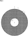
FIG 3 einen Querschnitt durch einen Kurzschlussring mit erfindungsgemäßer Wabenstruktur, -
FIG 4 einen weiteren Querschnitt durch einen Kurzschlussring mit erfindungsgemäßer Wabenstruktur, -
FIG 5 einen Querschnitt durch einen Kurzschluss mit Kreisstruktur, -
FIG 6 einen Querschnitt durch einen Kurzschlussring mit Dreieckstruktur, -
FIG 7 einen Ablauf eines erfindungsgemäßen Verfahrens zur Herstellung. -
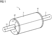
FIG 1 zeigt eine Ausgestaltung eines Rotors 1 einer elektrischen Maschine. Ein Rotor 1umfasst eine Welle 2,einen Rotorkern 3 sowie an den jeweiligen axialen Enden desRotorkerns 3je einen Kurzschlussring 41 bzw. 42.
-
FIG. 1 an embodiment of a rotor of an electrical machine, -
FIG. 2 a cross section through a squirrel cage, -
FIG. 3 a cross section through a short-circuit ring with inventive honeycomb structure, -
FIG. 4 a further cross section through a short-circuit ring with inventive honeycomb structure, -
FIG. 5 a cross section through a short circuit with circular structure, -
FIG. 6 a cross section through a short-circuit ring with triangular structure, -
FIG. 7 a sequence of a method according to the invention for the production. -
FIG. 1 shows an embodiment of a rotor 1 of an electric machine. A rotor 1 comprises ashaft 2, arotor core 3 and at the respective axial ends of therotor core 3 each have a short-circuit ring
Zudem zeigt
Die Käfigstäbe können aus Kupfer und/oder Aluminium oder deren Legierungen bestehen, Kupfer und/oder Aluminium oder deren Legierungen aufweisen oder die erfindungsgemäße Wabenstruktur - wie in
Die Wabenstruktur umfasst einen Wabenstrang sowie eine Wabenfüllung. Der Wabenstrang weist vorzugsweise ein Material einer ersten Festigkeit, vorzugsweise Stahl und/oder Titan oder deren Legierungen, auf. Die Wabenfüllung weist ein Material einer zweiten Festigkeit auf, vorzugsweise Kupfer und/oder Aluminium oder deren Legierungen.The honeycomb structure comprises a honeycomb strand and a honeycomb filling. The honeycomb strand preferably comprises a material of a first strength, preferably steel and / or titanium or their alloys. The honeycomb filling comprises a material of a second strength, preferably copper and / or aluminum or their alloys.
Anschließend gibt es zwei Möglichkeiten: Entweder es werden über Möglichkeit A im Verfahrensschritt S2 bereits vorgefertigte Kupferstäbe in die vorhandenen Nuten eingefügt. Diese Kupferstäbe erfüllen die Funktion der Käfigstäbe des Käfigläufers. Anschließend werden im Verfahrensschritt S4 Kurzschlussringe mittels eines additiven Fertigungsverfahrens an die jeweilig axialen Enden der Käfigstäbe angefügt. Hierbei werden die Kurzschlussringe mit der erfindungsgemäßen Wabenstruktur ausgestattet.Thereafter, there are two possibilities: Either prefabricated copper rods are inserted into the existing grooves via option A in method step S2. These copper rods perform the function of the cage bars of the squirrel cage. Subsequently, in method step S4, short-circuit rings are added to the respective axial ends of the cage bars by means of an additive manufacturing method. In this case, the short-circuit rings are equipped with the honeycomb structure according to the invention.
Ein alternativer Weg B ist der folgende: Nach dem Verfahrensschritt S1, also der Bereitstellung des Rotorpakets, werden sowohl die Nuten als auch die Aussparungen, welche für die Bildung des Kurzschlussrings bzw. der Kurzschlussringe vorgesehen sind, mittels des additiven Fertigungsverfahrens schichtweise im Verfahrensschritt S3 gefüllt.An alternative way B is the following: After method step S1, ie the provision of the rotor package, both the grooves and the recesses provided for the formation of the shorting ring or the shorting rings are filled in layers by method S3 in the additive manufacturing process ,
Auf diese Weise sind die Käfigstäbe bereits mit dem Kurzschlussring verbunden, da diese während einer additiven Fertigung hergestellt werden. Sowohl die Käfigstäbe als auch der Kurzschlussring bzw. die Kurzschlussringe an den jeweiligen axialen Enden des Rotorkerns verfügen über die erfindungsgemäße Wabenstruktur und somit über eine Stabilität bringende Armierung mittels des Wabenstrangs aus Stahl und/oder Titan oder deren Legierungen. Der Stromfluss wird effizient durch die Wabenfüllung aus Kupfer und/oder Aluminium oder deren Legierungen gewährleistet.In this way, the cage bars are already connected to the shorting ring, as they are produced during an additive manufacturing. Both the cage bars and the short-circuit ring or the short-circuit rings at the respective axial ends of the rotor core have the honeycomb structure according to the invention and thus a stability bringing reinforcement by means of the honeycomb strand of steel and / or titanium or their alloys. The flow of current is efficiently ensured by the honeycomb filling of copper and / or aluminum or their alloys.
Claims (14)
wobei mittels eines Materials einer ersten Festigkeit ein Wabenstrang (7) ausgebildet wird, wobei der Wabenstrang (7) aus wenigstens zwei unterschiedlichen Wabenschichten ausgebildet wird,
wobei mittels eines Materials einer gegenüber der ersten Festigkeit geringeren zweiten Festigkeit eine Wabenfüllung (8) ausgebildet wird.Method for producing a rotor (1) of an electrical machine,
wherein a honeycomb strand (7) is formed by means of a material of a first strength, wherein the honeycomb strand (7) is formed from at least two different honeycomb layers,
wherein a honeycomb filling (8) is formed by means of a material of a second strength lower than the first strength.
wobei mittels eines Materials einer gegenüber der ersten Festigkeit geringeren zweiten Festigkeit, vorzugsweise Kupfer und/oder Aluminium oder deren Legierungen, eine Wabenfüllung (8) ausgebildet ist.Shorting ring for a rotor (1) of an electric machine, wherein by means of a material of a first strength, preferably steel and / or titanium or their alloys, a honeycomb strand (7) is formed, wherein the honeycomb strand (7) is formed of at least two different honeycomb layers .
wherein a honeycomb filling (8) is formed by means of a material of a lower second strength than the first strength, preferably copper and / or aluminum or their alloys.
Priority Applications (2)
| Application Number | Priority Date | Filing Date | Title |
|---|---|---|---|
| EP17204676.5A EP3493371A1 (en) | 2017-11-30 | 2017-11-30 | Reinforced cage rotor |
| PCT/EP2018/079135 WO2019105660A1 (en) | 2017-11-30 | 2018-10-24 | Reinforced cage rotor |
Applications Claiming Priority (1)
| Application Number | Priority Date | Filing Date | Title |
|---|---|---|---|
| EP17204676.5A EP3493371A1 (en) | 2017-11-30 | 2017-11-30 | Reinforced cage rotor |
Publications (1)
| Publication Number | Publication Date |
|---|---|
| EP3493371A1 true EP3493371A1 (en) | 2019-06-05 |
Family
ID=60515294
Family Applications (1)
| Application Number | Title | Priority Date | Filing Date |
|---|---|---|---|
| EP17204676.5A Withdrawn EP3493371A1 (en) | 2017-11-30 | 2017-11-30 | Reinforced cage rotor |
Country Status (2)
| Country | Link |
|---|---|
| EP (1) | EP3493371A1 (en) |
| WO (1) | WO2019105660A1 (en) |
Cited By (1)
| Publication number | Priority date | Publication date | Assignee | Title |
|---|---|---|---|---|
| EP4362282A1 (en) * | 2022-10-26 | 2024-05-01 | Raw Power S.r.I. | Primary component for electric machines and electric motor comprising such component |
Citations (4)
| Publication number | Priority date | Publication date | Assignee | Title |
|---|---|---|---|---|
| DE19919899C1 (en) * | 1999-03-15 | 2000-09-07 | Loher Ag | Short circuit cage for electrical, preferably asynchronous, machine, has two metal half parts, pref. of cast copper, joined together and each with short circuit rods and a short circuit ring |
| US20070075603A1 (en) * | 2005-09-30 | 2007-04-05 | Whiddon Richard M | Labyrinthine end disk rotor |
| DE102015208196A1 (en) * | 2015-03-19 | 2016-09-22 | Siemens Aktiengesellschaft | Rotor for an electric machine and manufacturing process |
| EP3168969A1 (en) * | 2015-11-16 | 2017-05-17 | Siemens Aktiengesellschaft | Cage rotor |
-
2017
- 2017-11-30 EP EP17204676.5A patent/EP3493371A1/en not_active Withdrawn
-
2018
- 2018-10-24 WO PCT/EP2018/079135 patent/WO2019105660A1/en active Application Filing
Patent Citations (4)
| Publication number | Priority date | Publication date | Assignee | Title |
|---|---|---|---|---|
| DE19919899C1 (en) * | 1999-03-15 | 2000-09-07 | Loher Ag | Short circuit cage for electrical, preferably asynchronous, machine, has two metal half parts, pref. of cast copper, joined together and each with short circuit rods and a short circuit ring |
| US20070075603A1 (en) * | 2005-09-30 | 2007-04-05 | Whiddon Richard M | Labyrinthine end disk rotor |
| DE102015208196A1 (en) * | 2015-03-19 | 2016-09-22 | Siemens Aktiengesellschaft | Rotor for an electric machine and manufacturing process |
| EP3168969A1 (en) * | 2015-11-16 | 2017-05-17 | Siemens Aktiengesellschaft | Cage rotor |
Cited By (1)
| Publication number | Priority date | Publication date | Assignee | Title |
|---|---|---|---|---|
| EP4362282A1 (en) * | 2022-10-26 | 2024-05-01 | Raw Power S.r.I. | Primary component for electric machines and electric motor comprising such component |
Also Published As
| Publication number | Publication date |
|---|---|
| WO2019105660A1 (en) | 2019-06-06 |
Similar Documents
| Publication | Publication Date | Title |
|---|---|---|
| EP3595148B1 (en) | Method for producing a material layer and a material layer structure for a dynamoelectric rotary machine | |
| EP2961039B1 (en) | Mechanically stabilised rotor for a reluctance motor | |
| EP2999101B1 (en) | Bypass rotor | |
| EP3469694B1 (en) | Bypass rotor in particular for high rotational speeds | |
| EP3741031B1 (en) | Method for producing a squirrel-cage rotor | |
| WO2010100007A1 (en) | Squirrel-cage rotor | |
| WO2017089034A1 (en) | Cage rotor and method for the production thereof | |
| EP3809560A1 (en) | Magnetic sheet stack, method for producing same and electrical machine | |
| EP3577746B1 (en) | Manufacture of a rotor using additive manufacturing | |
| EP2885858B1 (en) | Cage rotor for an electric machine | |
| EP3493371A1 (en) | Reinforced cage rotor | |
| WO2017097500A1 (en) | Rotor, method for producing a rotor, asynchronous machine, and vehicle | |
| WO2019149430A1 (en) | Short-circuit ring for connecting to cage bars | |
| EP2957025B1 (en) | Squirrel cage for a squirrel-cage rotor, and production method | |
| DE102015224574A1 (en) | Rotor, method of manufacturing a rotor, asynchronous machine and vehicle | |
| DE102015202004A1 (en) | Squirrel-cage rotor with stable short-circuit ring for an electrical asynchronous machine and method of making the same | |
| EP3393016A1 (en) | Short circuit rotor and method for producing a short circuit rotor | |
| EP3627661B1 (en) | Cage rotor and manufacture of a cage rotor | |
| DE102020210565B4 (en) | Process for producing a composite component | |
| EP3595146A1 (en) | Rotor having a short circuit cage, method of manufacturing | |
| DE102019123552A1 (en) | Process for the production of a rotor, rotor and asynchronous motor | |
| EP4277096A1 (en) | Rotor of a cage rotor motor and method for producing the same | |
| WO2022043353A1 (en) | Active part of an electric machine, having a printed conductor | |
| DE102019008849A1 (en) | Rotor laminated core for a rotor of an electrical machine and method for its production | |
| EP3425779A1 (en) | Cage rotor for an asynchronous machine |
Legal Events
| Date | Code | Title | Description |
|---|---|---|---|
| PUAI | Public reference made under article 153(3) epc to a published international application that has entered the european phase |
Free format text: ORIGINAL CODE: 0009012 |
|
| AK | Designated contracting states |
Kind code of ref document: A1 Designated state(s): AL AT BE BG CH CY CZ DE DK EE ES FI FR GB GR HR HU IE IS IT LI LT LU LV MC MK MT NL NO PL PT RO RS SE SI SK SM TR |
|
| AX | Request for extension of the european patent |
Extension state: BA ME |
|
| STAA | Information on the status of an ep patent application or granted ep patent |
Free format text: STATUS: THE APPLICATION IS DEEMED TO BE WITHDRAWN |
|
| 18D | Application deemed to be withdrawn |
Effective date: 20191206 |