EP3493294A1 - Battery carrier - Google Patents
Battery carrier Download PDFInfo
- Publication number
- EP3493294A1 EP3493294A1 EP18209643.8A EP18209643A EP3493294A1 EP 3493294 A1 EP3493294 A1 EP 3493294A1 EP 18209643 A EP18209643 A EP 18209643A EP 3493294 A1 EP3493294 A1 EP 3493294A1
- Authority
- EP
- European Patent Office
- Prior art keywords
- battery
- face
- bottom flange
- locking part
- carrier
- Prior art date
- Legal status (The legal status is an assumption and is not a legal conclusion. Google has not performed a legal analysis and makes no representation as to the accuracy of the status listed.)
- Granted
Links
Images


Classifications
-
- B—PERFORMING OPERATIONS; TRANSPORTING
- B60—VEHICLES IN GENERAL
- B60R—VEHICLES, VEHICLE FITTINGS, OR VEHICLE PARTS, NOT OTHERWISE PROVIDED FOR
- B60R16/00—Electric or fluid circuits specially adapted for vehicles and not otherwise provided for; Arrangement of elements of electric or fluid circuits specially adapted for vehicles and not otherwise provided for
- B60R16/02—Electric or fluid circuits specially adapted for vehicles and not otherwise provided for; Arrangement of elements of electric or fluid circuits specially adapted for vehicles and not otherwise provided for electric constitutive elements
- B60R16/04—Arrangement of batteries
-
- B—PERFORMING OPERATIONS; TRANSPORTING
- B60—VEHICLES IN GENERAL
- B60L—PROPULSION OF ELECTRICALLY-PROPELLED VEHICLES; SUPPLYING ELECTRIC POWER FOR AUXILIARY EQUIPMENT OF ELECTRICALLY-PROPELLED VEHICLES; ELECTRODYNAMIC BRAKE SYSTEMS FOR VEHICLES IN GENERAL; MAGNETIC SUSPENSION OR LEVITATION FOR VEHICLES; MONITORING OPERATING VARIABLES OF ELECTRICALLY-PROPELLED VEHICLES; ELECTRIC SAFETY DEVICES FOR ELECTRICALLY-PROPELLED VEHICLES
- B60L50/00—Electric propulsion with power supplied within the vehicle
- B60L50/50—Electric propulsion with power supplied within the vehicle using propulsion power supplied by batteries or fuel cells
- B60L50/60—Electric propulsion with power supplied within the vehicle using propulsion power supplied by batteries or fuel cells using power supplied by batteries
- B60L50/64—Constructional details of batteries specially adapted for electric vehicles
-
- H—ELECTRICITY
- H01—ELECTRIC ELEMENTS
- H01M—PROCESSES OR MEANS, e.g. BATTERIES, FOR THE DIRECT CONVERSION OF CHEMICAL ENERGY INTO ELECTRICAL ENERGY
- H01M50/00—Constructional details or processes of manufacture of the non-active parts of electrochemical cells other than fuel cells, e.g. hybrid cells
- H01M50/20—Mountings; Secondary casings or frames; Racks, modules or packs; Suspension devices; Shock absorbers; Transport or carrying devices; Holders
- H01M50/256—Carrying devices, e.g. belts
-
- H—ELECTRICITY
- H01—ELECTRIC ELEMENTS
- H01M—PROCESSES OR MEANS, e.g. BATTERIES, FOR THE DIRECT CONVERSION OF CHEMICAL ENERGY INTO ELECTRICAL ENERGY
- H01M50/00—Constructional details or processes of manufacture of the non-active parts of electrochemical cells other than fuel cells, e.g. hybrid cells
- H01M50/20—Mountings; Secondary casings or frames; Racks, modules or packs; Suspension devices; Shock absorbers; Transport or carrying devices; Holders
- H01M50/262—Mountings; Secondary casings or frames; Racks, modules or packs; Suspension devices; Shock absorbers; Transport or carrying devices; Holders with fastening means, e.g. locks
-
- B—PERFORMING OPERATIONS; TRANSPORTING
- B60—VEHICLES IN GENERAL
- B60K—ARRANGEMENT OR MOUNTING OF PROPULSION UNITS OR OF TRANSMISSIONS IN VEHICLES; ARRANGEMENT OR MOUNTING OF PLURAL DIVERSE PRIME-MOVERS IN VEHICLES; AUXILIARY DRIVES FOR VEHICLES; INSTRUMENTATION OR DASHBOARDS FOR VEHICLES; ARRANGEMENTS IN CONNECTION WITH COOLING, AIR INTAKE, GAS EXHAUST OR FUEL SUPPLY OF PROPULSION UNITS IN VEHICLES
- B60K6/00—Arrangement or mounting of plural diverse prime-movers for mutual or common propulsion, e.g. hybrid propulsion systems comprising electric motors and internal combustion engines
- B60K6/20—Arrangement or mounting of plural diverse prime-movers for mutual or common propulsion, e.g. hybrid propulsion systems comprising electric motors and internal combustion engines the prime-movers consisting of electric motors and internal combustion engines, e.g. HEVs
- B60K6/22—Arrangement or mounting of plural diverse prime-movers for mutual or common propulsion, e.g. hybrid propulsion systems comprising electric motors and internal combustion engines the prime-movers consisting of electric motors and internal combustion engines, e.g. HEVs characterised by apparatus, components or means specially adapted for HEVs
- B60K6/28—Arrangement or mounting of plural diverse prime-movers for mutual or common propulsion, e.g. hybrid propulsion systems comprising electric motors and internal combustion engines the prime-movers consisting of electric motors and internal combustion engines, e.g. HEVs characterised by apparatus, components or means specially adapted for HEVs characterised by the electric energy storing means, e.g. batteries or capacitors
-
- H—ELECTRICITY
- H01—ELECTRIC ELEMENTS
- H01M—PROCESSES OR MEANS, e.g. BATTERIES, FOR THE DIRECT CONVERSION OF CHEMICAL ENERGY INTO ELECTRICAL ENERGY
- H01M2220/00—Batteries for particular applications
- H01M2220/20—Batteries in motive systems, e.g. vehicle, ship, plane
-
- Y—GENERAL TAGGING OF NEW TECHNOLOGICAL DEVELOPMENTS; GENERAL TAGGING OF CROSS-SECTIONAL TECHNOLOGIES SPANNING OVER SEVERAL SECTIONS OF THE IPC; TECHNICAL SUBJECTS COVERED BY FORMER USPC CROSS-REFERENCE ART COLLECTIONS [XRACs] AND DIGESTS
- Y02—TECHNOLOGIES OR APPLICATIONS FOR MITIGATION OR ADAPTATION AGAINST CLIMATE CHANGE
- Y02T—CLIMATE CHANGE MITIGATION TECHNOLOGIES RELATED TO TRANSPORTATION
- Y02T10/00—Road transport of goods or passengers
- Y02T10/60—Other road transportation technologies with climate change mitigation effect
- Y02T10/70—Energy storage systems for electromobility, e.g. batteries
Definitions
- the present disclosure relates to a battery carrier for holding a battery that supplies electric power to electrical components, for example, in a vehicle.
- Vehicles such as automobiles include an auxiliary battery (which will be hereinafter referred to as a "battery”) that supplies electric power to electrical components including lights, on-vehicle computers, car audio equipment, and route guidance systems, for example.
- the battery has a substantially rectangular parallelepiped shape.
- the battery is placed on a support surface of a tray-like battery carrier and installed in an engine compartment, for example.
- Patent Document 1 indicated below discloses a battery carrier for holding a battery (10).
- the battery (10) includes bottom flanges (ribs 12F, 12B, 12R, 12L) at bottom portions of its four side faces, respectively.
- the battery (10) is placed on a support surface (25) of a body (23) of the battery carrier, and a back bottom flange (rib 12B) and a right bottom flange (rib 12R) of the battery (10) are respectively held by corresponding holding portions (locking portions 27 and 28) located on a rear edge and a right side edge of the body (23).
- a front bottom flange (rib 12F) and a left bottom flange (rib 12L) of the battery (10) are further held, at a front-left corner of the battery (10), by a battery clamp (clamping member 22) between the battery clamp and the support surface (25).
- a battery clamp clamping member 22
- the battery carrier in accordance with an aspect of the disclosure is used for mounting a battery having a rectangular parallelepiped shape on a vehicle and holds the battery. More particularly, the battery carrier holds bottom flanges on bottom portions of a front face, a back face, a first side face, and a second side face, respectively, of the battery to hold the battery.
- the battery carrier includes a carrier base having a support surface of a rectangular shape on which the battery is placed.
- the carrier base includes holding portions in a rear edge portion and a first side edge portion of the support surface, respectively.
- the holding portions include holding faces facing the support surface and holding the bottom flanges on the back face and the first side face, respectively, between the holding faces and the support surface.
- the battery carrier further includes a battery clamp disposed in a corner formed between a front edge portion and a second side edge portion opposite the first side edge portion of the support surface of the carrier base.
- the battery clamp is fixed on the carrier base at a position further backward from the front face of the battery and beside the second side face of the battery.
- the battery clamp includes a front locking part located in front of the front face of the battery to lock the bottom flange on the front face, and a side locking part located beside the second side face of the battery to lock the bottom flange on the second side face.
- the front locking part includes a plate-like front facing portion facing the front face of the battery and a plate-like front pressing portion extending from a lower edge of the front facing portion along a top face of the bottom flange on the front face to contact the top surface of the bottom flange on the front face.
- the front locking part of the battery clamp receives a force, from the rearward tilted battery, that contains primary components in the direction along the plate face of the front facing portion.
- the battery clamp including a plate-like front facing portion facing the front face of the battery, has high rigidity against the force received from the rearward tilted battery, which contributes to prevention of removal of the battery.
- the side locking part may include a plate-like side facing portion facing the second side face of the battery and a plate-like side pressing portion extending from a lower edge of the side facing portion along a top face of the bottom flange on the second side face to contact the top face of the bottom flange on the second side face.
- the front facing portion and the side facing portion may be connected to form an L shape.
- the battery clamp receives, from the rearward tilted battery, a force containing primary components in the directions along the plate faces of the front facing portion and the side facing portion. Therefore, the portion formed in an L-shape by the front facing portion and the side facing portion has a high rigidity against the force received from the rearward tilted battery. This high rigidity contributes to prevention of removal of the battery.
- the front pressing portion and the side pressing portion may be separated from each other.
- the battery clamp including the front facing portion and the side facing portion that are connected with each other and the front pressing portion and the side pressing portion that are separated from each other, can be easily produced.
- the front facing portion may be configured to be spaced from the front face of the battery in normal times and to be tilted rearward with the rearward tilt of the battery and come into contact with the front face of the battery.
- the structure of the front facing portion which is normally spaced from the battery front face, prevents unnecessary force from acting on the battery.
- the battery carrier has an increased holding power for holding the battery in a rear crash of a vehicle.
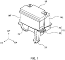
- FIG. 1 illustrates a battery carrier 12 that holds a battery
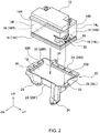
- FIG. 2 illustrates the battery carrier 12 and the battery 10 which is removed from the battery carrier 12.
- arrows FR, UP, and LH indicate forward, upward, and leftward of a vehicle, respectively.
- terms describing directions and orientations, such as “forward,” “rearward” or “backward,” “leftward,” “rightward,” “upward,” and “downward,” refer to directions and orientations with respect to a vehicle, unless otherwise specified.
- the battery 10 is disposed in an engine compartment in the front portion of a vehicle.
- the location where the battery 10 is disposed is not limited to the engine compartment, and the battery 10 may be disposed adjacent to a trunk in the rear portion of the vehicle, for example.
- the battery 10 has a substantially rectangular parallelepiped shape, and, when mounted in a vehicle, has a front face 14F facing forward, a back face 14B facing backward, a right side face 14R facing rightward, and a left side face 14L facing leftward.
- the battery 10 includes bottom flanges 16 protruding outward around the bottom portion of the battery 10.
- the bottom flange 16 disposed at the lower end; that is, at the bottom, of the front face 14F will be referred to as a front face bottom flange 16F; similarly, the bottom flanges 16 disposed on the back face 14B, the right side face 14R, and the left side face 14L, will be referred to as a back face bottom flange 16B, a right side face bottom flange 16R, and a left side face bottom flange 16L, respectively.
- the battery carrier 12 includes a carrier base 20 of a tray shape including a support surface 18 on which the battery 10 is placed, and a battery clamp 22 configured to be fixed to the carrier base 20 to hold the battery 10 in cooperation with the carrier base 20.
- the carrier base 20 includes three attachment legs 24 each having a bolt hole.
- the battery carrier 12 is fastened to a body of a vehicle by fastening the attachment legs 24 with bolts (not shown).
- the carrier base 20 includes a bottom plate 26 defining the support surface 18, and surrounding walls 28 disposed to surround the support surface 18.
- the surrounding wall 28 located at the front edge of the support surface 18 will be referred to as a front wall 28F; similarly, the surrounding walls 28 located at the back edge, the right edge, and the left edge of the support surface 18 will be referred to as a back wall 28B, a right side wall 28R, and a left side wall 28L, respectively.
- the back wall 28B and the right side wall 28R include a back face protruding portion 30B and a right side face protruding portion 30R protruding inward, respectively.
- the front wall 28F and the left side wall 28L include no such protruding portions corresponding to the back face protruding portion 30B and the right side face protruding portion 30R.
- the back face protruding portion 30B extends in the leftward-rightward direction along an inner wall face of the back wall 28B.
- the back face protruding portion 30B may be disposed along the entire length of the back wall 28B or along a portion of the back wall 28B.
- the back face protruding portion 30B includes an undersurface facing the support surface 18.
- the back wall 28B and the back face protruding portion 30B together form a holding portion that holds the back face bottom flange 16B at the rear edge portion of the support surface 18.
- the undersurface of the back face protruding portion 30B serves as a holding face.
- the right side face protruding portion 30R extends in the forward-rearward direction along an inner wall face of the right side wall 28R.
- the right side face protruding portion 30R may be disposed along the entire length of the right side wall 28R or along a portion of the right side wall 28R.
- the right side face protruding portion 30R includes an undersurface facing the support surface 18.
- the right side wall 28R and the right side face protruding portion 30R together form a holding portion that holds the right side face bottom flange 16R at the right side edge portion of the support surface 18.
- the undersurface of the right side face protruding portion 30R serves as a holding face.
- the left side wall 28L includes a seat 32 protruding outward from the left side wall 28L.
- the battery clamp 22 is fixed to the seat 32 by means of a bolt 34. This fixing position; that is, the position of the bolt 34, is located further backward with respect to the front face 14F and also further leftward with respect to the left side face 14L.
- the battery clamp 22 is fixed in a corner formed by the front edge and the left side edge of the support surface 18.
- FIG. 3 illustrates the battery clamp 22.
- the battery clamp 22 includes a front locking part 36 configured to be located in front of the front face 14F of the battery 10 when the battery clamp 22 is fixed to the carrier base 20, a side locking part 38 configured to be located beside the left side face 14L of the battery 10, and a fixing piece 40 configured to be located on the seat 32 of the carrier base 20.
- the front locking part 36 locks the front face bottom flange 16F
- the side locking part 38 locks the left side face bottom flange 16L.
- the fixing piece 40 is fixed on the seat 32 of the carrier base 20 by means of the bolt 34.
- a support arm 42 is joined to the fixing piece 40. The support arm 42 is used to align the battery clamp 22 during mounting of the battery clamp 22. More specifically, after placing the battery 10 on the carrier base 20, the operator holds the upper end of the support arm 42 and moves the battery clamp 22 to align the hole in the fixing piece 40 with a nut formed in the seat 32, and then tightens the bolt 34.
- the side locking part 38 includes a plate-like side facing portion 44 facing the left side face 14L of the battery 10 and a plate-like side pressing portion 46 extending diagonally downward from the lower edge of the side facing portion 44.
- the side pressing portion 46 extends along the top face of the left side face bottom flange 16L of the battery 10 and is in contact with this top face to press the left side face bottom flange 16L downward toward the support surface 18.
- the fixing piece 40 extends leftward from the upper edge of the side facing portion 44.
- the front locking part 36 includes a plate-like front facing portion 48 facing the front face 14F of the battery 10 and a plate-like front pressing portion 50 extending diagonally downward from the lower edge of the front facing portion 48.
- the front facing portion 48 is continuous with the side facing portion 44 so that they form an L shape when viewed in a plan view.
- the front facing portion 48 and the side facing portion 44 have substantially the same height in the upward-downward direction and are continuous with each other while maintaining this height.
- the front pressing portion 50 extends along the top face of the front face bottom flange 16F of the battery 10 and is in contact with this top face to press the front face bottom flange 16F down toward the support surface 18.
- the front facing portion 48 includes a reinforcement flange 52 on its upper edge.
- the front facing portion 48 and the side facing portion 44 are continuous with each other; whereas the front pressing portion 50 and the side pressing portion 46 are not directly continuous with each other.
- This structure facilitates production of the battery clamp 22 by sheet metal processing.
- the front locking part 36, the side locking part 38, and the fixing piece 40 may be produced from a single piece of sheet metal through a plurality of press molding processes.
- the front pressing portion 50 and the side pressing portion 46, which are separated from each other, have bending portions in substantially straight lines, which facilitates press machining. After the press molding, the support arm 42 is further joined by welding, for example.
- FIG. 4 is a cross sectional view of the battery 10 and the battery carrier 12 in the direction orthogonal to the right-left direction of the vehicle, and particularly a cross sectional view across the front locking part 36.
- the front face bottom flange 16F and the back face bottom flange 16B each have a top surface which is downwardly sloped outward.
- the right side face bottom flange 16R and the left side face bottom flange 16L each similarly have a top surface which is downwardly sloped outward.
- the back face protruding portion 30B corresponding to the back face bottom flange 16B has an undersurface which is sloped along the top face of the back face bottom flange 16B.
- the back face bottom flange 16B is disposed between and held by the support surface 18 and the back face protruding portion 30B.
- the right side face protruding portion 30R similarly has an undersurface which is sloped along the right side face bottom flange 16R, and the right side face bottom flange 16R is disposed between and held by the support surface 18 and the right side face protruding portion 30R.
- the front pressing portion 50 of the front locking part 36 extends along the sloped top face of the front face bottom flange 16F, and is disposed in an inclined manner.
- the side pressing portion 46 of the side locking part 38 similarly extends along the sloped top face of the left side face bottom flange 16L and is disposed in an inclined manner.
- Tightening the bolt 34 causes the front pressing portion 48 and the side pressing portion 46 to press the front face bottom flange 16F and the left side face bottom flange 16L, respectively. As the top surfaces of these flanges are sloped, this pressing force also works in the direction along the support surface 18 and presses the battery 10 toward the back wall 28B and the right side wall 28R.
- the front facing portion 48 is tilted forward and is spaced from the front face 14F of the battery 10.
- the side facing portion 44 is similarly tilted leftward and is spaced from the left side face 14L of the battery 10.
- the front facing portion 48 and the side facing portion 44 which are not in contact with the front face 14F and the left side face 14L of the battery 10, respectively, apply no unexpected force to the front face 14F and the left side face 14L, respectively.
- the battery clamp 22 which is fixed, by means of the bolt 34, to the position further backward from the front face 14F of the battery 10 and beside the left side face 14L of the battery 10, rotates clockwise in FIG. 4 about this fixing point. This rotation would further cause the front locking part 36 and the front facing portion 48 thereof to rotate clockwise.
- FIG. 5 is a diagram for explaining a relative motion of the front locking part 36 with respect to the battery 10 in a rear crash.
- the front locking part 36 is in the position indicated by a solid line before the crash, that is, in the normal state, where the front facing portion 48 is inclined forward and is spaced from the front face 14F of the battery 10.
- the front locking part 36 upon receiving the upward force from the front face bottom flange 16F, is lifted and rotates clockwise to come into contact with the front face 14F of the battery 10.
- the front locking part 36 is at the relative position indicated by a dashed and single-dotted line in FIG. 5 as the front locking part 36D, with respect to the battery 10.
- the front locking part 36 receives substantially the upward force from the front face bottom flange 16F.
- the direction of this force intersects the plate face of the front pressing portion 50 and is also substantially within the plate face of the front facing portion 48.
- the front locking part 36 including the front facing portion 48 in addition to the front pressing portion 50 therefore has higher rigidity against the force received in a rear crash than the front locking part 36 including only the front pressing portion 50. This structure reduces deformation of the front locking part 36, and holds the battery 10 more reliably to thereby prevent removal of the battery 10.
- the side locking part 38 receives a force along the direction within the plate face of the side facing portion 44, and therefore has high rigidity against this force.
- the front facing portion 48 and the side facing portion 44 which are continuous with each other while maintaining the same dimension in the vertical direction, secure rigidity in the connecting portion and regulate the relative movement of the front locking part 36 with respect to the side locking part 38 to thereby prevent deformation of the battery clamp 22. This structure holds the battery 10 more reliably to thereby prevent removal of the battery 10.
- the battery carrier 12 includes the battery clamp 22 disposed in the front-left corner of the battery 10 to fasten the battery 10, the present disclosure is not limited to this example.
- a battery carrier having a symmetrical configuration with respect to the battery carrier 12 may include the battery clamp in the front-right corner of the battery 10.
- the front facing portion 48 of the battery clamp 22 may be in contact with the front face 14F of the battery 10 during normal operation; that is, before a crash.
Landscapes
- Engineering & Computer Science (AREA)
- Chemical & Material Sciences (AREA)
- Chemical Kinetics & Catalysis (AREA)
- Electrochemistry (AREA)
- General Chemical & Material Sciences (AREA)
- Mechanical Engineering (AREA)
- Sustainable Development (AREA)
- Sustainable Energy (AREA)
- Power Engineering (AREA)
- Transportation (AREA)
- Life Sciences & Earth Sciences (AREA)
- Battery Mounting, Suspending (AREA)
- Arrangement Or Mounting Of Propulsion Units For Vehicles (AREA)
Abstract
Description
- The disclosure of Japanese Patent Application No.
2017-232045 filed on December 1, 2017 - The present disclosure relates to a battery carrier for holding a battery that supplies electric power to electrical components, for example, in a vehicle.
- Vehicles such as automobiles include an auxiliary battery (which will be hereinafter referred to as a "battery") that supplies electric power to electrical components including lights, on-vehicle computers, car audio equipment, and route guidance systems, for example. The battery has a substantially rectangular parallelepiped shape. The battery is placed on a support surface of a tray-like battery carrier and installed in an engine compartment, for example.
- Patent Document 1 indicated below discloses a battery carrier for holding a battery (10). The battery (10) includes bottom flanges (ribs 12F, 12B, 12R, 12L) at bottom portions of its four side faces, respectively. The battery (10) is placed on a support surface (25) of a body (23) of the battery carrier, and a back bottom flange (rib 12B) and a right bottom flange (rib 12R) of the battery (10) are respectively held by corresponding holding portions (locking portions 27 and 28) located on a rear edge and a right side edge of the body (23). A front bottom flange (rib 12F) and a left bottom flange (rib 12L) of the battery (10) are further held, at a front-left corner of the battery (10), by a battery clamp (clamping member 22) between the battery clamp and the support surface (25). The names of members and reference numerals described above in parentheses are used in Patent Document 1 and are not relevant to those used in the description of the embodiments of the present application.
- [Patent Document 1]
JP 2017-114221 A - Vehicle crashes induce a force that would remove the battery off from the battery carrier. There are therefore possibilities for modification in the holding power of the battery carrier for holding the battery, especially in the holding power of the battery clamp.
- The battery carrier in accordance with an aspect of the disclosure is used for mounting a battery having a rectangular parallelepiped shape on a vehicle and holds the battery. More particularly, the battery carrier holds bottom flanges on bottom portions of a front face, a back face, a first side face, and a second side face, respectively, of the battery to hold the battery. The battery carrier includes a carrier base having a support surface of a rectangular shape on which the battery is placed. The carrier base includes holding portions in a rear edge portion and a first side edge portion of the support surface, respectively. The holding portions include holding faces facing the support surface and holding the bottom flanges on the back face and the first side face, respectively, between the holding faces and the support surface. The battery carrier further includes a battery clamp disposed in a corner formed between a front edge portion and a second side edge portion opposite the first side edge portion of the support surface of the carrier base. The battery clamp is fixed on the carrier base at a position further backward from the front face of the battery and beside the second side face of the battery. The battery clamp includes a front locking part located in front of the front face of the battery to lock the bottom flange on the front face, and a side locking part located beside the second side face of the battery to lock the bottom flange on the second side face. The front locking part includes a plate-like front facing portion facing the front face of the battery and a plate-like front pressing portion extending from a lower edge of the front facing portion along a top face of the bottom flange on the front face to contact the top surface of the bottom flange on the front face.
- In a rear crash of a vehicle, a force acts on the battery that would cause the battery to be tilted rearward, which would further lift the front edge of the battery upward. With the front edge of the battery, the battery clamp, particularly the front locking part, is also lifted. As the battery clamp is fixed to the battery carrier at a position further backward from the front face of the battery, the front locking part is also lifted, with the battery front edge, toward the rearward tilted direction; the front facing portion comes into contact with the battery front face for holding. As such, not only the front pressing portion but also the front facing portion holds the front edge of the battery that is lifted upward, so that removal of the battery can be prevented.
- The front locking part of the battery clamp receives a force, from the rearward tilted battery, that contains primary components in the direction along the plate face of the front facing portion. The battery clamp, including a plate-like front facing portion facing the front face of the battery, has high rigidity against the force received from the rearward tilted battery, which contributes to prevention of removal of the battery.
- The side locking part may include a plate-like side facing portion facing the second side face of the battery and a plate-like side pressing portion extending from a lower edge of the side facing portion along a top face of the bottom flange on the second side face to contact the top face of the bottom flange on the second side face. The front facing portion and the side facing portion may be connected to form an L shape.
- The battery clamp receives, from the rearward tilted battery, a force containing primary components in the directions along the plate faces of the front facing portion and the side facing portion. Therefore, the portion formed in an L-shape by the front facing portion and the side facing portion has a high rigidity against the force received from the rearward tilted battery. This high rigidity contributes to prevention of removal of the battery.
- The front pressing portion and the side pressing portion may be separated from each other. The battery clamp, including the front facing portion and the side facing portion that are connected with each other and the front pressing portion and the side pressing portion that are separated from each other, can be easily produced.
- The front facing portion may be configured to be spaced from the front face of the battery in normal times and to be tilted rearward with the rearward tilt of the battery and come into contact with the front face of the battery. The structure of the front facing portion, which is normally spaced from the battery front face, prevents unnecessary force from acting on the battery.
- The battery carrier has an increased holding power for holding the battery in a rear crash of a vehicle.
- An embodiment of the present disclosure will be described by reference to the following figures, wherein:
-
FIG. 1 is a perspective view illustrating a battery carrier according to an embodiment, with a battery mounted thereon; -
FIG. 2 is an exploded perspective view of the battery and the battery carrier; -
FIG. 3 is a perspective view of a battery clamp; -
FIG. 4 is a cross sectional view of the battery and the battery carrier; and -
FIG. 5 is a diagram illustrating a motion of a front locking part of the battery clamp in a rear crash. - An embodiment of the present disclosure will be described with reference to the drawings.
FIG. 1 illustrates abattery carrier 12 that holds abattery 10, andFIG. 2 illustrates thebattery carrier 12 and thebattery 10 which is removed from thebattery carrier 12. In the drawings, arrows FR, UP, and LH indicate forward, upward, and leftward of a vehicle, respectively. In the following description, terms describing directions and orientations, such as "forward," "rearward" or "backward," "leftward," "rightward," "upward," and "downward," refer to directions and orientations with respect to a vehicle, unless otherwise specified. - The
battery 10 is disposed in an engine compartment in the front portion of a vehicle. However, the location where thebattery 10 is disposed is not limited to the engine compartment, and thebattery 10 may be disposed adjacent to a trunk in the rear portion of the vehicle, for example. Thebattery 10 has a substantially rectangular parallelepiped shape, and, when mounted in a vehicle, has afront face 14F facing forward, aback face 14B facing backward, aright side face 14R facing rightward, and aleft side face 14L facing leftward. Thebattery 10 includesbottom flanges 16 protruding outward around the bottom portion of thebattery 10. In the following description, thebottom flange 16 disposed at the lower end; that is, at the bottom, of thefront face 14F will be referred to as a frontface bottom flange 16F; similarly, thebottom flanges 16 disposed on theback face 14B, theright side face 14R, and theleft side face 14L, will be referred to as a backface bottom flange 16B, a right sideface bottom flange 16R, and a left sideface bottom flange 16L, respectively. - The
battery carrier 12 includes acarrier base 20 of a tray shape including asupport surface 18 on which thebattery 10 is placed, and abattery clamp 22 configured to be fixed to thecarrier base 20 to hold thebattery 10 in cooperation with thecarrier base 20. - The
carrier base 20 includes threeattachment legs 24 each having a bolt hole. Thebattery carrier 12 is fastened to a body of a vehicle by fastening theattachment legs 24 with bolts (not shown). Thecarrier base 20 includes abottom plate 26 defining thesupport surface 18, and surroundingwalls 28 disposed to surround thesupport surface 18. In the following description, the surroundingwall 28 located at the front edge of thesupport surface 18 will be referred to as afront wall 28F; similarly, the surroundingwalls 28 located at the back edge, the right edge, and the left edge of thesupport surface 18 will be referred to as aback wall 28B, aright side wall 28R, and aleft side wall 28L, respectively. - The
back wall 28B and theright side wall 28R include a backface protruding portion 30B and a right sideface protruding portion 30R protruding inward, respectively. In contrast, thefront wall 28F and theleft side wall 28L include no such protruding portions corresponding to the backface protruding portion 30B and the right sideface protruding portion 30R. - The back
face protruding portion 30B extends in the leftward-rightward direction along an inner wall face of theback wall 28B. The backface protruding portion 30B may be disposed along the entire length of theback wall 28B or along a portion of theback wall 28B. The backface protruding portion 30B includes an undersurface facing thesupport surface 18. When thebattery 10 is mounted on thecarrier base 20, the backface bottom flange 16B of thebattery 10 is held between the undersurface of the backface protruding portion 30B and thesupport surface 18. In other words, theback wall 28B and the backface protruding portion 30B together form a holding portion that holds the backface bottom flange 16B at the rear edge portion of thesupport surface 18. In this structure, the undersurface of the backface protruding portion 30B serves as a holding face. - The right side
face protruding portion 30R extends in the forward-rearward direction along an inner wall face of theright side wall 28R. The right sideface protruding portion 30R may be disposed along the entire length of theright side wall 28R or along a portion of theright side wall 28R. The right sideface protruding portion 30R includes an undersurface facing thesupport surface 18. When thebattery 10 is mounted on thecarrier base 20, the right side facebottom flange 16R of thebattery 10 is held between the undersurface of the right sideface protruding portion 30R and thesupport surface 18. In other words, theright side wall 28R and the right sideface protruding portion 30R together form a holding portion that holds the right side facebottom flange 16R at the right side edge portion of thesupport surface 18. In this structure, the undersurface of the right sideface protruding portion 30R serves as a holding face. - The
left side wall 28L includes aseat 32 protruding outward from theleft side wall 28L. Thebattery clamp 22 is fixed to theseat 32 by means of abolt 34. This fixing position; that is, the position of thebolt 34, is located further backward with respect to thefront face 14F and also further leftward with respect to theleft side face 14L. Thebattery clamp 22 is fixed in a corner formed by the front edge and the left side edge of thesupport surface 18. -
FIG. 3 illustrates thebattery clamp 22. Thebattery clamp 22 includes afront locking part 36 configured to be located in front of thefront face 14F of thebattery 10 when thebattery clamp 22 is fixed to thecarrier base 20, aside locking part 38 configured to be located beside theleft side face 14L of thebattery 10, and a fixingpiece 40 configured to be located on theseat 32 of thecarrier base 20. Thefront locking part 36 locks the front facebottom flange 16F, and theside locking part 38 locks the left side facebottom flange 16L. The fixingpiece 40 is fixed on theseat 32 of thecarrier base 20 by means of thebolt 34. The backface protruding portion 30B and the right sideface protruding portion 30R, and the front lockingpart 36 and theside locking part 38 together restrict thebottom flanges 16 to hold thebattery 10 in thebattery carrier 12. Asupport arm 42 is joined to the fixingpiece 40. Thesupport arm 42 is used to align thebattery clamp 22 during mounting of thebattery clamp 22. More specifically, after placing thebattery 10 on thecarrier base 20, the operator holds the upper end of thesupport arm 42 and moves thebattery clamp 22 to align the hole in the fixingpiece 40 with a nut formed in theseat 32, and then tightens thebolt 34. - The
side locking part 38 includes a plate-likeside facing portion 44 facing theleft side face 14L of thebattery 10 and a plate-likeside pressing portion 46 extending diagonally downward from the lower edge of theside facing portion 44. Theside pressing portion 46 extends along the top face of the left side facebottom flange 16L of thebattery 10 and is in contact with this top face to press the left side facebottom flange 16L downward toward thesupport surface 18. The fixingpiece 40 extends leftward from the upper edge of theside facing portion 44. - The
front locking part 36 includes a plate-likefront facing portion 48 facing thefront face 14F of thebattery 10 and a plate-likefront pressing portion 50 extending diagonally downward from the lower edge of thefront facing portion 48. Thefront facing portion 48 is continuous with theside facing portion 44 so that they form an L shape when viewed in a plan view. Thefront facing portion 48 and theside facing portion 44 have substantially the same height in the upward-downward direction and are continuous with each other while maintaining this height. The frontpressing portion 50 extends along the top face of the front facebottom flange 16F of thebattery 10 and is in contact with this top face to press the front facebottom flange 16F down toward thesupport surface 18. Thefront facing portion 48 includes areinforcement flange 52 on its upper edge. - The
front facing portion 48 and theside facing portion 44 are continuous with each other; whereas thefront pressing portion 50 and theside pressing portion 46 are not directly continuous with each other. This structure facilitates production of thebattery clamp 22 by sheet metal processing. Thefront locking part 36, theside locking part 38, and the fixingpiece 40 may be produced from a single piece of sheet metal through a plurality of press molding processes. The frontpressing portion 50 and theside pressing portion 46, which are separated from each other, have bending portions in substantially straight lines, which facilitates press machining. After the press molding, thesupport arm 42 is further joined by welding, for example. -
FIG. 4 is a cross sectional view of thebattery 10 and thebattery carrier 12 in the direction orthogonal to the right-left direction of the vehicle, and particularly a cross sectional view across thefront locking part 36. As illustrated inFIG. 4 , the front facebottom flange 16F and the backface bottom flange 16B each have a top surface which is downwardly sloped outward. The right side facebottom flange 16R and the left side facebottom flange 16L each similarly have a top surface which is downwardly sloped outward. The backface protruding portion 30B corresponding to the backface bottom flange 16B has an undersurface which is sloped along the top face of the backface bottom flange 16B. The backface bottom flange 16B is disposed between and held by thesupport surface 18 and the backface protruding portion 30B. Although not shown, the right sideface protruding portion 30R similarly has an undersurface which is sloped along the right side facebottom flange 16R, and the right side facebottom flange 16R is disposed between and held by thesupport surface 18 and the right sideface protruding portion 30R. - The front
pressing portion 50 of the front lockingpart 36 extends along the sloped top face of the front facebottom flange 16F, and is disposed in an inclined manner. Although not shown, theside pressing portion 46 of theside locking part 38 similarly extends along the sloped top face of the left side facebottom flange 16L and is disposed in an inclined manner. - Tightening the
bolt 34 causes thefront pressing portion 48 and theside pressing portion 46 to press the front facebottom flange 16F and the left side facebottom flange 16L, respectively. As the top surfaces of these flanges are sloped, this pressing force also works in the direction along thesupport surface 18 and presses thebattery 10 toward theback wall 28B and theright side wall 28R. This brings the top surface of the backface bottom flange 16B and the undersurface of the backface protruding portion 30B into intimate contact with each other, and also brings the top surface of the right side facebottom flange 16R and the undersurface of the right sideface protruding portion 30R into intimate contact with each other, so that the backface bottom flange 16B and the right side facebottom flange 16R are held without looseness. - The
front facing portion 48 is tilted forward and is spaced from thefront face 14F of thebattery 10. Theside facing portion 44 is similarly tilted leftward and is spaced from theleft side face 14L of thebattery 10. Thefront facing portion 48 and theside facing portion 44, which are not in contact with thefront face 14F and theleft side face 14L of thebattery 10, respectively, apply no unexpected force to thefront face 14F and the left side face 14L, respectively. - In a rear crash, while the
battery carrier 12 moves forward with the vehicle body, thebattery 10 attempts to remain in the current position because of inertia. As thebattery 10 is held by thebattery carrier 12 at the bottom portion, the forward movement of thebattery carrier 12 generates moment M exerted on thebattery 10 to cause thebattery 10 to rotate clockwise inFIG. 4 around its rear edge portion. This moment M works to cause thebattery 10 to tilt rearward and cause the front edge, such as the front facebottom flange 16F, of thebattery 10 to lift upward. This force is further transmitted to thefront locking part 36 of thebattery clamp 22. Thebattery clamp 22, which is fixed, by means of thebolt 34, to the position further backward from thefront face 14F of thebattery 10 and beside theleft side face 14L of thebattery 10, rotates clockwise inFIG. 4 about this fixing point. This rotation would further cause thefront locking part 36 and thefront facing portion 48 thereof to rotate clockwise. -
FIG. 5 is a diagram for explaining a relative motion of the front lockingpart 36 with respect to thebattery 10 in a rear crash. Thefront locking part 36 is in the position indicated by a solid line before the crash, that is, in the normal state, where thefront facing portion 48 is inclined forward and is spaced from thefront face 14F of thebattery 10. In a rear crash, thefront locking part 36, upon receiving the upward force from the front facebottom flange 16F, is lifted and rotates clockwise to come into contact with thefront face 14F of thebattery 10. At this time, thefront locking part 36 is at the relative position indicated by a dashed and single-dotted line inFIG. 5 as thefront locking part 36D, with respect to thebattery 10. As illustrated, thefront facing portion 48D is in contact with thefront face 14F of thebattery 10. Thus, thefront locking part 36D contacts thebattery 10 not only with the front pressingportion 50 but also with thefront facing portion 48D, to hold thebattery 10 more reliably and prevent thebattery 10 from being removed from thebattery carrier 10. - In a rear crash, the
front locking part 36 receives substantially the upward force from the front facebottom flange 16F. The direction of this force intersects the plate face of the front pressingportion 50 and is also substantially within the plate face of thefront facing portion 48. Thefront locking part 36 including thefront facing portion 48 in addition to the front pressingportion 50 therefore has higher rigidity against the force received in a rear crash than the front lockingpart 36 including only the front pressingportion 50. This structure reduces deformation of the front lockingpart 36, and holds thebattery 10 more reliably to thereby prevent removal of thebattery 10. - Further, the
side locking part 38 receives a force along the direction within the plate face of theside facing portion 44, and therefore has high rigidity against this force. In particular, thefront facing portion 48 and theside facing portion 44, which are continuous with each other while maintaining the same dimension in the vertical direction, secure rigidity in the connecting portion and regulate the relative movement of the front lockingpart 36 with respect to theside locking part 38 to thereby prevent deformation of thebattery clamp 22. This structure holds thebattery 10 more reliably to thereby prevent removal of thebattery 10. - While in the above example, the
battery carrier 12 includes thebattery clamp 22 disposed in the front-left corner of thebattery 10 to fasten thebattery 10, the present disclosure is not limited to this example. For example, a battery carrier having a symmetrical configuration with respect to thebattery carrier 12, may include the battery clamp in the front-right corner of thebattery 10. Further, thefront facing portion 48 of thebattery clamp 22 may be in contact with thefront face 14F of thebattery 10 during normal operation; that is, before a crash. - 10 battery, 12 battery carrier, 14F front face, 14B back face, 14R right side face (first side face), 14L left side face (second side face), 16 bottom flange, 16F front face bottom flange, 16B back face bottom flange, 16R right side face bottom flange, 16L left side face bottom flange, 18 support surface, 20 carrier base, 22 battery clamp, 24 attachment leg, 26 bottom plate, 28 surrounding wall, 28F front wall, 28B back wall (holding portion), 28R right side wall (holding portion), 28L left side wall, 30B back face protruding portion (holding portion), 30R right side face protruding (holding portion), 32 seat, 34 bolt, 36 front locking part, 38 side locking part, 40 fixing piece, 42 support arm, 44 side facing portion, 46 side pressing portion, 48 front facing portion, 50 front pressing portion, 52 reinforcing flange.
Claims (4)
- A battery carrier (12) for holding a battery (10), for use in mounting the battery (10) in a vehicle, the battery (10) having a rectangular parallelepiped shape and comprising bottom flanges (16, 16F, 16B, 16R, 16L) on bottom portions of a front face (14F), a back face (14B), a first side face (14R), and a second side face (14L), respectively,
the battery carrier (12) comprising:a carrier base (20) having a support surface (18) of a rectangular shape on which the battery (10) is placed, the carrier base (20) comprising holding portions (28B, 28R, 30B, 30R) in a rear edge portion and a first side edge portion of the support surface (18), respectively, the holding portions (28B, 28R, 30B, 30R) comprising holding faces facing the support surface (18), the holding faces holding the bottom flanges (16B, 16R) on the back face (14B) and the first side (14R) face, respectively, between the holding faces and the support surface (18); anda battery clamp (22) disposed in a corner formed between a front edge portion and a second side edge portion of the support surface (18) of the carrier base (20), the battery clamp (22) being fixed on the carrier base (20) at a position further backward from the front face (14F) of the battery (10) and beside the second side face (14L) of the battery (10), the battery clamp (22) comprising a front locking part (36) located in front of the front face (14F) of the battery (10) to lock the bottom flange (16, 16F) on the front face (14F), and a side locking part (38) located beside the second side face (14L) of the battery (10) to lock the bottom flange (16, 16L) on the second side face (14L),the front locking part (36) comprising a plate-like front facing portion (48) facing the front face (14F) of the battery (10) and a plate-like front pressing portion (50) extending from a lower edge of the front facing portion (48) along a top face of the bottom flange (16, 16F) on the front face (14F) to contact the top face of the bottom flange (16, 16F) on the front face (14F). - The battery carrier (12) according to claim 1, wherein
the side locking part (38) comprises a plate-like side facing portion (44) facing the second side face (14L) of the battery (10) and a plate-like side pressing portion (46) extending from a lower edge of the side facing portion (44) along a top face of the bottom flange (16, 16L) on the second side face (14L) to contact the top face of the bottom flange (16, 16L) on the second side face (14L), and
the front facing portion (48) and the side facing portion (44) are connected in an L shape. - The battery carrier (12) according to claim 2, wherein
the front pressing portion (50) and the side pressing portion (46) are separated from each other. - The battery carrier (12) according to any of claims 1 to 3, wherein
the front facing portion (48) is spaced from the front face (14F) of the battery (10) during a normal operation, and is tilted rearward with rearward tilt of the battery (10) in a rear crash to come into contact with the front face (14F) of the battery (10).
Applications Claiming Priority (1)
| Application Number | Priority Date | Filing Date | Title |
|---|---|---|---|
| JP2017232045A JP6879182B2 (en) | 2017-12-01 | 2017-12-01 | Battery carrier |
Publications (2)
| Publication Number | Publication Date |
|---|---|
| EP3493294A1 true EP3493294A1 (en) | 2019-06-05 |
| EP3493294B1 EP3493294B1 (en) | 2020-03-04 |
Family
ID=64564735
Family Applications (1)
| Application Number | Title | Priority Date | Filing Date |
|---|---|---|---|
| EP18209643.8A Active EP3493294B1 (en) | 2017-12-01 | 2018-11-30 | Battery carrier |
Country Status (4)
| Country | Link |
|---|---|
| US (1) | US10322689B1 (en) |
| EP (1) | EP3493294B1 (en) |
| JP (1) | JP6879182B2 (en) |
| CN (1) | CN109927652B (en) |
Cited By (1)
| Publication number | Priority date | Publication date | Assignee | Title |
|---|---|---|---|---|
| EP3573133A1 (en) * | 2018-05-23 | 2019-11-27 | Toyota Jidosha Kabushiki Kaisha | Battery holding structure |
Families Citing this family (11)
| Publication number | Priority date | Publication date | Assignee | Title |
|---|---|---|---|---|
| JP6544311B2 (en) * | 2016-07-14 | 2019-07-17 | トヨタ自動車株式会社 | In-vehicle equipment fixed structure |
| JP6935776B2 (en) * | 2018-03-15 | 2021-09-15 | トヨタ自動車株式会社 | Holding structure of power storage device |
| JP7006514B2 (en) * | 2018-06-07 | 2022-02-10 | トヨタ自動車株式会社 | Battery mounting structure |
| JP7004415B2 (en) * | 2018-06-29 | 2022-01-21 | 株式会社クボタ | Battery stand and work equipment equipped with it |
| US10631429B2 (en) * | 2018-07-13 | 2020-04-21 | Ford Global Technologies, Llc | Vehicle power module assembly |
| CN110444709A (en) * | 2019-08-14 | 2019-11-12 | 朱良彬 | A kind of new-energy automobile anti-collision structure |
| KR102930967B1 (en) * | 2020-07-20 | 2026-02-25 | 주식회사 엘지에너지솔루션 | Tray for secondary battery and tray assembly comprising the same |
| JP7424352B2 (en) * | 2021-06-23 | 2024-01-30 | トヨタ自動車株式会社 | battery support structure |
| JP7725980B2 (en) * | 2021-09-29 | 2025-08-20 | スズキ株式会社 | Support structure for electrical components |
| JP7380728B2 (en) * | 2022-03-15 | 2023-11-15 | いすゞ自動車株式会社 | Fixing structure and fixing method of vehicle battery box |
| FR3164161A1 (en) * | 2024-07-02 | 2026-01-09 | Stellantis Auto Sas | AUTOMOTIVE ON-BOARD BATTERY SUPPORT SYSTEM WITH ELECTRICAL BOX |
Citations (3)
| Publication number | Priority date | Publication date | Assignee | Title |
|---|---|---|---|---|
| US20150236312A1 (en) * | 2014-02-20 | 2015-08-20 | Dr. Ing. H.C. F. Porsche Aktiengesellschaft | Battery tray for a battery housing of a motor vehicle battery |
| JP2016137853A (en) * | 2015-01-28 | 2016-08-04 | トヨタ自動車株式会社 | Battery holder for vehicles |
| US20170174160A1 (en) * | 2015-12-22 | 2017-06-22 | Toyota Jidosha Kabushiki Kaisha | Battery carrier |
Family Cites Families (57)
| Publication number | Priority date | Publication date | Assignee | Title |
|---|---|---|---|---|
| US2947373A (en) * | 1958-08-11 | 1960-08-02 | Ford Motor Co | Battery mounting apparatus |
| US3557895A (en) * | 1969-01-24 | 1971-01-26 | Frank W Thomas | Battery securing means |
| US3894607A (en) * | 1972-11-15 | 1975-07-15 | James E Brock | Clamping apparatus for a plurality of batteries |
| US3866704A (en) * | 1973-02-08 | 1975-02-18 | East Penn Manufacturing Compan | Battery holddown |
| US3834479A (en) * | 1973-02-08 | 1974-09-10 | East Peru Mfg Co Inc | Battery holddown |
| DE2543308C3 (en) * | 1975-09-27 | 1979-12-20 | Daimler-Benz Ag, 7000 Stuttgart | Device for holding a storage battery |
| US4444853A (en) * | 1983-07-01 | 1984-04-24 | Globe-Union Inc. | Storage battery construction |
| US4535863A (en) * | 1983-08-26 | 1985-08-20 | Becker John R | Battery security and hold-down device |
| JPS60156053U (en) * | 1984-03-28 | 1985-10-17 | 日産自動車株式会社 | Automobile battery mounting structure |
| US4632201A (en) * | 1984-05-11 | 1986-12-30 | Kay Ronald D | Latch mechanism for a battery holder |
| US4756978A (en) * | 1986-11-19 | 1988-07-12 | Walter Nitcher | Battery and mount |
| US4854540A (en) * | 1988-02-29 | 1989-08-08 | LTL Industries Ltd. | Vehicle battery mounting apparatus |
| FI86926C (en) * | 1988-04-14 | 1992-10-26 | Neste Oy | FAUNTEKANISM FOER ACKUMULATOR |
| US5082075A (en) * | 1989-09-07 | 1992-01-21 | Globe-Union Inc. | Method and apparatus for thermal control of automotive components |
| USD321856S (en) * | 1989-09-28 | 1991-11-26 | Attwood Corporation | Battery storage tray |
| US5086860A (en) * | 1990-06-04 | 1992-02-11 | Saturn Corporation | Vehicular battery retainer and shield |
| US5052198A (en) * | 1990-07-30 | 1991-10-01 | Elektrek Partnership | Battery lock and hold-down device |
| US5222711A (en) * | 1992-01-27 | 1993-06-29 | Bell Stuart D | Battery hold-down |
| US5377947A (en) * | 1993-08-23 | 1995-01-03 | Johnson; Jerome | Battery holddown |
| US5547160A (en) * | 1993-08-23 | 1996-08-20 | Quick Cable Corporation | Battery holddown |
| US5484667A (en) * | 1993-09-07 | 1996-01-16 | Gnb Battery Technologies Inc. | Spacers for lead-acid batteries |
| US5543248A (en) * | 1995-02-17 | 1996-08-06 | Globe-Union Inc. | Thermal stabilization shield for storage batteries |
| US5643693A (en) * | 1995-10-30 | 1997-07-01 | Yazaki Corporation | Battery-mounted power distribution module |
| US6161810A (en) * | 1999-02-16 | 2000-12-19 | Delphi Technologies, Inc. | Torsion rod holddown apparatus for a battery |
| JP3533979B2 (en) * | 1999-03-05 | 2004-06-07 | 日産自動車株式会社 | Power head mounting structure for electric vehicles |
| US6230833B1 (en) * | 1999-07-06 | 2001-05-15 | Visteon Global Technologies, Inc. | Storage battery tuning of engine air intake system |
| US6230834B1 (en) * | 1999-09-16 | 2001-05-15 | Daimlerchrysler Corporation | Battery mounting system |
| JP4259694B2 (en) * | 1999-09-29 | 2009-04-30 | 富士重工業株式会社 | Vehicle battery mounting structure |
| US6290013B1 (en) * | 1999-11-18 | 2001-09-18 | Daimlerchrysler Corporation | Battery tray having acid management features |
| US6564893B2 (en) * | 2000-12-12 | 2003-05-20 | Murray Lipman | Pre-wired battery box for rapid installation and connection of batteries |
| JP3923281B2 (en) * | 2001-06-13 | 2007-05-30 | 本田技研工業株式会社 | Mounting structure for vehicle equipment |
| DE10230492A1 (en) * | 2002-07-06 | 2004-01-15 | A. Raymond & Cie | Device for fastening a housing, in particular that of a motor vehicle battery, to a carrier plate |
| JP3754016B2 (en) * | 2002-10-16 | 2006-03-08 | 川崎重工業株式会社 | Vehicle battery mounting structure |
| US6871829B2 (en) * | 2003-01-23 | 2005-03-29 | Quick Cable Corporation | Telescopically adjustable battery holddown |
| JP3867060B2 (en) * | 2003-03-28 | 2007-01-10 | 三菱電機株式会社 | Vehicle power supply system |
| DE10314030B4 (en) * | 2003-03-28 | 2005-07-14 | A. Raymond & Cie | Device for fastening a housing, in particular that of a motor vehicle battery, to a carrier |
| US6827169B1 (en) * | 2003-08-01 | 2004-12-07 | Daimlerchrysler Corporation | Force distributing top mount battery retention system |
| US7384704B2 (en) * | 2003-12-18 | 2008-06-10 | General Motors Corporation | Methods and apparatus for controlling the temperature of an automobile battery |
| JP2005297754A (en) * | 2004-04-12 | 2005-10-27 | Nissan Motor Co Ltd | Support structure for side parts for vehicles |
| US7357206B2 (en) * | 2005-04-06 | 2008-04-15 | The Little Tikes Company | Child's riding vehicle |
| FR2891515B1 (en) * | 2005-10-05 | 2008-02-29 | Raymond Et Cie Soc En Commandi | DEVICE FOR FIXING A BATTERY |
| US8517131B2 (en) * | 2010-07-23 | 2013-08-27 | Honda Motor Co., Ltd. | Battery mounting assembly |
| DE102010036684B4 (en) * | 2010-07-28 | 2023-09-21 | Dr. Ing. H.C. F. Porsche Aktiengesellschaft | Fastening device for a battery in a motor vehicle and motor vehicle with such a fastening device |
| DE102011121515B4 (en) * | 2010-12-20 | 2016-06-30 | Mazda Motor Corp. | Battery arrangement structure of a vehicle and method for arranging a battery |
| JP5370436B2 (en) * | 2011-08-24 | 2013-12-18 | トヨタ自動車株式会社 | Battery mounting structure |
| JP5364767B2 (en) * | 2011-09-26 | 2013-12-11 | 富士重工業株式会社 | Battery support structure for vehicle |
| US8808894B2 (en) * | 2012-01-25 | 2014-08-19 | Chrysler Group Llc | Battery tray retaining system |
| US8822056B2 (en) * | 2012-05-30 | 2014-09-02 | Honda Motor Co., Ltd. | Methods and systems for supporting a battery |
| JP6015190B2 (en) * | 2012-07-23 | 2016-10-26 | 三菱自動車工業株式会社 | Battery box |
| US9640787B2 (en) * | 2012-09-10 | 2017-05-02 | Richard C. Lee | Electrified battery tray assemblies |
| JP5704142B2 (en) * | 2012-10-09 | 2015-04-22 | トヨタ自動車株式会社 | In-vehicle device protection structure and electric vehicle |
| JP5835247B2 (en) * | 2013-02-27 | 2015-12-24 | 株式会社デンソー | Battery unit |
| DE102013216555B4 (en) * | 2013-08-21 | 2023-02-23 | Volkswagen Aktiengesellschaft | Fastening device for a battery in a motor vehicle |
| JP5829706B2 (en) * | 2014-02-25 | 2015-12-09 | 富士重工業株式会社 | Automotive battery |
| DE102015210926A1 (en) * | 2015-06-15 | 2016-12-15 | Volkswagen Aktiengesellschaft | Fixing device for a battery |
| JP6528674B2 (en) * | 2015-12-24 | 2019-06-12 | トヨタ自動車株式会社 | Vehicle rear structure |
| JP6812800B2 (en) * | 2017-01-05 | 2021-01-13 | スズキ株式会社 | Vehicle battery holding structure |
-
2017
- 2017-12-01 JP JP2017232045A patent/JP6879182B2/en active Active
-
2018
- 2018-11-23 CN CN201811405305.5A patent/CN109927652B/en active Active
- 2018-11-26 US US16/199,794 patent/US10322689B1/en active Active
- 2018-11-30 EP EP18209643.8A patent/EP3493294B1/en active Active
Patent Citations (4)
| Publication number | Priority date | Publication date | Assignee | Title |
|---|---|---|---|---|
| US20150236312A1 (en) * | 2014-02-20 | 2015-08-20 | Dr. Ing. H.C. F. Porsche Aktiengesellschaft | Battery tray for a battery housing of a motor vehicle battery |
| JP2016137853A (en) * | 2015-01-28 | 2016-08-04 | トヨタ自動車株式会社 | Battery holder for vehicles |
| US20170174160A1 (en) * | 2015-12-22 | 2017-06-22 | Toyota Jidosha Kabushiki Kaisha | Battery carrier |
| JP2017114221A (en) | 2015-12-22 | 2017-06-29 | トヨタ自動車株式会社 | Battery carrier |
Cited By (1)
| Publication number | Priority date | Publication date | Assignee | Title |
|---|---|---|---|---|
| EP3573133A1 (en) * | 2018-05-23 | 2019-11-27 | Toyota Jidosha Kabushiki Kaisha | Battery holding structure |
Also Published As
| Publication number | Publication date |
|---|---|
| US10322689B1 (en) | 2019-06-18 |
| JP6879182B2 (en) | 2021-06-02 |
| JP2019098931A (en) | 2019-06-24 |
| CN109927652B (en) | 2022-07-01 |
| EP3493294B1 (en) | 2020-03-04 |
| US20190168699A1 (en) | 2019-06-06 |
| CN109927652A (en) | 2019-06-25 |
Similar Documents
| Publication | Publication Date | Title |
|---|---|---|
| EP3493294B1 (en) | Battery carrier | |
| US10897034B2 (en) | Battery fastening system and method | |
| US10266136B2 (en) | Vehicle substructure | |
| CN113525092B (en) | Electric vehicle | |
| JP2011108411A (en) | Terminal block | |
| EP3573133A1 (en) | Battery holding structure | |
| JP6544311B2 (en) | In-vehicle equipment fixed structure | |
| CN107054038A (en) | Vehicle | |
| EP2179893A1 (en) | Attaching structure | |
| JP3749396B2 (en) | Battery mounting device | |
| JP2011097711A (en) | Electrical junction box | |
| US8666105B2 (en) | Subwoofer mounting bracket | |
| JPH0556546U (en) | Battery locking structure for battery and battery storage structure for battery | |
| JP2023107098A (en) | Protective structure of in-vehicle equipment | |
| US8454211B2 (en) | Vehicle headlamp | |
| JP7224193B2 (en) | Battery structure fixing structure | |
| US20250058717A1 (en) | Base plate attachment structure | |
| US12252082B2 (en) | In-vehicle component protection structure | |
| JP2016004660A (en) | Battery terminal and battery terminal unit | |
| US20260103065A1 (en) | Vehicle underfloor structure | |
| CN120879108A (en) | Storage battery fixing device | |
| JP3683736B2 (en) | Card holder and unit mounting frame provided on the cluster lid | |
| JPH0565032A (en) | Fuel tank mounting structure | |
| JPH06312672A (en) | Electric vehicle floor structure | |
| JP2604632Y2 (en) | Battery locking structure for battery and vehicle storage structure for battery |
Legal Events
| Date | Code | Title | Description |
|---|---|---|---|
| PUAI | Public reference made under article 153(3) epc to a published international application that has entered the european phase |
Free format text: ORIGINAL CODE: 0009012 |
|
| STAA | Information on the status of an ep patent application or granted ep patent |
Free format text: STATUS: REQUEST FOR EXAMINATION WAS MADE |
|
| 17P | Request for examination filed |
Effective date: 20181130 |
|
| AK | Designated contracting states |
Kind code of ref document: A1 Designated state(s): AL AT BE BG CH CY CZ DE DK EE ES FI FR GB GR HR HU IE IS IT LI LT LU LV MC MK MT NL NO PL PT RO RS SE SI SK SM TR |
|
| AX | Request for extension of the european patent |
Extension state: BA ME |
|
| GRAJ | Information related to disapproval of communication of intention to grant by the applicant or resumption of examination proceedings by the epo deleted |
Free format text: ORIGINAL CODE: EPIDOSDIGR1 |
|
| STAA | Information on the status of an ep patent application or granted ep patent |
Free format text: STATUS: GRANT OF PATENT IS INTENDED |
|
| GRAP | Despatch of communication of intention to grant a patent |
Free format text: ORIGINAL CODE: EPIDOSNIGR1 |
|
| RIC1 | Information provided on ipc code assigned before grant |
Ipc: H01M 2/10 20060101AFI20190911BHEP |
|
| INTG | Intention to grant announced |
Effective date: 20191002 |
|
| GRAS | Grant fee paid |
Free format text: ORIGINAL CODE: EPIDOSNIGR3 |
|
| GRAA | (expected) grant |
Free format text: ORIGINAL CODE: 0009210 |
|
| STAA | Information on the status of an ep patent application or granted ep patent |
Free format text: STATUS: THE PATENT HAS BEEN GRANTED |
|
| AK | Designated contracting states |
Kind code of ref document: B1 Designated state(s): AL AT BE BG CH CY CZ DE DK EE ES FI FR GB GR HR HU IE IS IT LI LT LU LV MC MK MT NL NO PL PT RO RS SE SI SK SM TR |
|
| REG | Reference to a national code |
Ref country code: GB Ref legal event code: FG4D |
|
| REG | Reference to a national code |
Ref country code: CH Ref legal event code: EP |
|
| REG | Reference to a national code |
Ref country code: AT Ref legal event code: REF Ref document number: 1241402 Country of ref document: AT Kind code of ref document: T Effective date: 20200315 |
|
| REG | Reference to a national code |
Ref country code: DE Ref legal event code: R096 Ref document number: 602018002869 Country of ref document: DE |
|
| REG | Reference to a national code |
Ref country code: IE Ref legal event code: FG4D |
|
| PG25 | Lapsed in a contracting state [announced via postgrant information from national office to epo] |
Ref country code: FI Free format text: LAPSE BECAUSE OF FAILURE TO SUBMIT A TRANSLATION OF THE DESCRIPTION OR TO PAY THE FEE WITHIN THE PRESCRIBED TIME-LIMIT Effective date: 20200304 Ref country code: RS Free format text: LAPSE BECAUSE OF FAILURE TO SUBMIT A TRANSLATION OF THE DESCRIPTION OR TO PAY THE FEE WITHIN THE PRESCRIBED TIME-LIMIT Effective date: 20200304 Ref country code: NO Free format text: LAPSE BECAUSE OF FAILURE TO SUBMIT A TRANSLATION OF THE DESCRIPTION OR TO PAY THE FEE WITHIN THE PRESCRIBED TIME-LIMIT Effective date: 20200604 |
|
| REG | Reference to a national code |
Ref country code: NL Ref legal event code: MP Effective date: 20200304 |
|
| PG25 | Lapsed in a contracting state [announced via postgrant information from national office to epo] |
Ref country code: GR Free format text: LAPSE BECAUSE OF FAILURE TO SUBMIT A TRANSLATION OF THE DESCRIPTION OR TO PAY THE FEE WITHIN THE PRESCRIBED TIME-LIMIT Effective date: 20200605 Ref country code: HR Free format text: LAPSE BECAUSE OF FAILURE TO SUBMIT A TRANSLATION OF THE DESCRIPTION OR TO PAY THE FEE WITHIN THE PRESCRIBED TIME-LIMIT Effective date: 20200304 Ref country code: BG Free format text: LAPSE BECAUSE OF FAILURE TO SUBMIT A TRANSLATION OF THE DESCRIPTION OR TO PAY THE FEE WITHIN THE PRESCRIBED TIME-LIMIT Effective date: 20200604 Ref country code: LV Free format text: LAPSE BECAUSE OF FAILURE TO SUBMIT A TRANSLATION OF THE DESCRIPTION OR TO PAY THE FEE WITHIN THE PRESCRIBED TIME-LIMIT Effective date: 20200304 Ref country code: SE Free format text: LAPSE BECAUSE OF FAILURE TO SUBMIT A TRANSLATION OF THE DESCRIPTION OR TO PAY THE FEE WITHIN THE PRESCRIBED TIME-LIMIT Effective date: 20200304 |
|
| REG | Reference to a national code |
Ref country code: LT Ref legal event code: MG4D |
|
| PG25 | Lapsed in a contracting state [announced via postgrant information from national office to epo] |
Ref country code: NL Free format text: LAPSE BECAUSE OF FAILURE TO SUBMIT A TRANSLATION OF THE DESCRIPTION OR TO PAY THE FEE WITHIN THE PRESCRIBED TIME-LIMIT Effective date: 20200304 |
|
| PG25 | Lapsed in a contracting state [announced via postgrant information from national office to epo] |
Ref country code: IS Free format text: LAPSE BECAUSE OF FAILURE TO SUBMIT A TRANSLATION OF THE DESCRIPTION OR TO PAY THE FEE WITHIN THE PRESCRIBED TIME-LIMIT Effective date: 20200704 Ref country code: PT Free format text: LAPSE BECAUSE OF FAILURE TO SUBMIT A TRANSLATION OF THE DESCRIPTION OR TO PAY THE FEE WITHIN THE PRESCRIBED TIME-LIMIT Effective date: 20200729 Ref country code: ES Free format text: LAPSE BECAUSE OF FAILURE TO SUBMIT A TRANSLATION OF THE DESCRIPTION OR TO PAY THE FEE WITHIN THE PRESCRIBED TIME-LIMIT Effective date: 20200304 Ref country code: LT Free format text: LAPSE BECAUSE OF FAILURE TO SUBMIT A TRANSLATION OF THE DESCRIPTION OR TO PAY THE FEE WITHIN THE PRESCRIBED TIME-LIMIT Effective date: 20200304 Ref country code: RO Free format text: LAPSE BECAUSE OF FAILURE TO SUBMIT A TRANSLATION OF THE DESCRIPTION OR TO PAY THE FEE WITHIN THE PRESCRIBED TIME-LIMIT Effective date: 20200304 Ref country code: CZ Free format text: LAPSE BECAUSE OF FAILURE TO SUBMIT A TRANSLATION OF THE DESCRIPTION OR TO PAY THE FEE WITHIN THE PRESCRIBED TIME-LIMIT Effective date: 20200304 Ref country code: EE Free format text: LAPSE BECAUSE OF FAILURE TO SUBMIT A TRANSLATION OF THE DESCRIPTION OR TO PAY THE FEE WITHIN THE PRESCRIBED TIME-LIMIT Effective date: 20200304 Ref country code: SM Free format text: LAPSE BECAUSE OF FAILURE TO SUBMIT A TRANSLATION OF THE DESCRIPTION OR TO PAY THE FEE WITHIN THE PRESCRIBED TIME-LIMIT Effective date: 20200304 Ref country code: SK Free format text: LAPSE BECAUSE OF FAILURE TO SUBMIT A TRANSLATION OF THE DESCRIPTION OR TO PAY THE FEE WITHIN THE PRESCRIBED TIME-LIMIT Effective date: 20200304 |
|
| REG | Reference to a national code |
Ref country code: AT Ref legal event code: MK05 Ref document number: 1241402 Country of ref document: AT Kind code of ref document: T Effective date: 20200304 |
|
| REG | Reference to a national code |
Ref country code: DE Ref legal event code: R079 Ref document number: 602018002869 Country of ref document: DE Free format text: PREVIOUS MAIN CLASS: H01M0002100000 Ipc: H01M0050200000 |
|
| REG | Reference to a national code |
Ref country code: DE Ref legal event code: R097 Ref document number: 602018002869 Country of ref document: DE |
|
| PLBE | No opposition filed within time limit |
Free format text: ORIGINAL CODE: 0009261 |
|
| STAA | Information on the status of an ep patent application or granted ep patent |
Free format text: STATUS: NO OPPOSITION FILED WITHIN TIME LIMIT |
|
| PG25 | Lapsed in a contracting state [announced via postgrant information from national office to epo] |
Ref country code: AT Free format text: LAPSE BECAUSE OF FAILURE TO SUBMIT A TRANSLATION OF THE DESCRIPTION OR TO PAY THE FEE WITHIN THE PRESCRIBED TIME-LIMIT Effective date: 20200304 Ref country code: DK Free format text: LAPSE BECAUSE OF FAILURE TO SUBMIT A TRANSLATION OF THE DESCRIPTION OR TO PAY THE FEE WITHIN THE PRESCRIBED TIME-LIMIT Effective date: 20200304 Ref country code: IT Free format text: LAPSE BECAUSE OF FAILURE TO SUBMIT A TRANSLATION OF THE DESCRIPTION OR TO PAY THE FEE WITHIN THE PRESCRIBED TIME-LIMIT Effective date: 20200304 |
|
| 26N | No opposition filed |
Effective date: 20201207 |
|
| PG25 | Lapsed in a contracting state [announced via postgrant information from national office to epo] |
Ref country code: PL Free format text: LAPSE BECAUSE OF FAILURE TO SUBMIT A TRANSLATION OF THE DESCRIPTION OR TO PAY THE FEE WITHIN THE PRESCRIBED TIME-LIMIT Effective date: 20200304 |
|
| PG25 | Lapsed in a contracting state [announced via postgrant information from national office to epo] |
Ref country code: MC Free format text: LAPSE BECAUSE OF FAILURE TO SUBMIT A TRANSLATION OF THE DESCRIPTION OR TO PAY THE FEE WITHIN THE PRESCRIBED TIME-LIMIT Effective date: 20200304 |
|
| PG25 | Lapsed in a contracting state [announced via postgrant information from national office to epo] |
Ref country code: LU Free format text: LAPSE BECAUSE OF NON-PAYMENT OF DUE FEES Effective date: 20201130 |
|
| REG | Reference to a national code |
Ref country code: DE Ref legal event code: R084 Ref document number: 602018002869 Country of ref document: DE |
|
| REG | Reference to a national code |
Ref country code: BE Ref legal event code: MM Effective date: 20201130 |
|
| REG | Reference to a national code |
Ref country code: IE Ref legal event code: MM4A |
|
| REG | Reference to a national code |
Ref country code: GB Ref legal event code: 746 Effective date: 20210929 |
|
| PG25 | Lapsed in a contracting state [announced via postgrant information from national office to epo] |
Ref country code: IE Free format text: LAPSE BECAUSE OF NON-PAYMENT OF DUE FEES Effective date: 20201130 |
|
| PG25 | Lapsed in a contracting state [announced via postgrant information from national office to epo] |
Ref country code: TR Free format text: LAPSE BECAUSE OF FAILURE TO SUBMIT A TRANSLATION OF THE DESCRIPTION OR TO PAY THE FEE WITHIN THE PRESCRIBED TIME-LIMIT Effective date: 20200304 Ref country code: MT Free format text: LAPSE BECAUSE OF FAILURE TO SUBMIT A TRANSLATION OF THE DESCRIPTION OR TO PAY THE FEE WITHIN THE PRESCRIBED TIME-LIMIT Effective date: 20200304 Ref country code: CY Free format text: LAPSE BECAUSE OF FAILURE TO SUBMIT A TRANSLATION OF THE DESCRIPTION OR TO PAY THE FEE WITHIN THE PRESCRIBED TIME-LIMIT Effective date: 20200304 |
|
| PG25 | Lapsed in a contracting state [announced via postgrant information from national office to epo] |
Ref country code: MK Free format text: LAPSE BECAUSE OF FAILURE TO SUBMIT A TRANSLATION OF THE DESCRIPTION OR TO PAY THE FEE WITHIN THE PRESCRIBED TIME-LIMIT Effective date: 20200304 Ref country code: AL Free format text: LAPSE BECAUSE OF FAILURE TO SUBMIT A TRANSLATION OF THE DESCRIPTION OR TO PAY THE FEE WITHIN THE PRESCRIBED TIME-LIMIT Effective date: 20200304 |
|
| REG | Reference to a national code |
Ref country code: CH Ref legal event code: PL |
|
| PG25 | Lapsed in a contracting state [announced via postgrant information from national office to epo] |
Ref country code: BE Free format text: LAPSE BECAUSE OF NON-PAYMENT OF DUE FEES Effective date: 20201130 |
|
| P01 | Opt-out of the competence of the unified patent court (upc) registered |
Effective date: 20230427 |
|
| PG25 | Lapsed in a contracting state [announced via postgrant information from national office to epo] |
Ref country code: LI Free format text: LAPSE BECAUSE OF NON-PAYMENT OF DUE FEES Effective date: 20220630 Ref country code: CH Free format text: LAPSE BECAUSE OF NON-PAYMENT OF DUE FEES Effective date: 20220630 |
|
| PG25 | Lapsed in a contracting state [announced via postgrant information from national office to epo] |
Ref country code: SI Free format text: LAPSE BECAUSE OF FAILURE TO SUBMIT A TRANSLATION OF THE DESCRIPTION OR TO PAY THE FEE WITHIN THE PRESCRIBED TIME-LIMIT Effective date: 20200304 |
|
| PGFP | Annual fee paid to national office [announced via postgrant information from national office to epo] |
Ref country code: FR Payment date: 20250930 Year of fee payment: 8 |
|
| PGFP | Annual fee paid to national office [announced via postgrant information from national office to epo] |
Ref country code: DE Payment date: 20250930 Year of fee payment: 8 |
|
| PGFP | Annual fee paid to national office [announced via postgrant information from national office to epo] |
Ref country code: GB Payment date: 20251001 Year of fee payment: 8 |