EP3492964B1 - Spectacle glass and method for its production - Google Patents
Spectacle glass and method for its production Download PDFInfo
- Publication number
- EP3492964B1 EP3492964B1 EP18214846.0A EP18214846A EP3492964B1 EP 3492964 B1 EP3492964 B1 EP 3492964B1 EP 18214846 A EP18214846 A EP 18214846A EP 3492964 B1 EP3492964 B1 EP 3492964B1
- Authority
- EP
- European Patent Office
- Prior art keywords
- volume
- volume elements
- spectacle lens
- grid
- element group
- Prior art date
- Legal status (The legal status is an assumption and is not a legal conclusion. Google has not performed a legal analysis and makes no representation as to the accuracy of the status listed.)
- Active
Links
- 238000004519 manufacturing process Methods 0.000 title description 43
- 238000000034 method Methods 0.000 title description 34
- 239000011521 glass Substances 0.000 title description 21
- 239000000463 material Substances 0.000 claims description 71
- 230000008859 change Effects 0.000 claims description 13
- 230000007704 transition Effects 0.000 claims description 10
- 230000000149 penetrating effect Effects 0.000 claims description 4
- 230000003287 optical effect Effects 0.000 description 24
- 239000010410 layer Substances 0.000 description 20
- 238000000576 coating method Methods 0.000 description 19
- 230000008569 process Effects 0.000 description 19
- 239000000654 additive Substances 0.000 description 16
- 239000011248 coating agent Substances 0.000 description 14
- 230000000996 additive effect Effects 0.000 description 13
- 239000000047 product Substances 0.000 description 13
- 238000007639 printing Methods 0.000 description 12
- 230000000694 effects Effects 0.000 description 11
- 238000010146 3D printing Methods 0.000 description 10
- -1 CR 607 Chemical compound 0.000 description 9
- 238000013461 design Methods 0.000 description 9
- 238000010586 diagram Methods 0.000 description 9
- 238000005516 engineering process Methods 0.000 description 9
- 239000011265 semifinished product Substances 0.000 description 9
- 239000000758 substrate Substances 0.000 description 9
- 238000009499 grossing Methods 0.000 description 8
- 229920003229 poly(methyl methacrylate) Polymers 0.000 description 8
- 229920001296 polysiloxane Polymers 0.000 description 7
- 229920002578 polythiourethane polymer Polymers 0.000 description 7
- 230000000750 progressive effect Effects 0.000 description 7
- 239000006117 anti-reflective coating Substances 0.000 description 6
- 238000013459 approach Methods 0.000 description 6
- 238000007641 inkjet printing Methods 0.000 description 6
- 239000000203 mixture Substances 0.000 description 6
- 238000000926 separation method Methods 0.000 description 6
- 239000000126 substance Substances 0.000 description 6
- 239000000835 fiber Substances 0.000 description 5
- 229910052500 inorganic mineral Inorganic materials 0.000 description 5
- 239000011707 mineral Substances 0.000 description 5
- 239000000178 monomer Substances 0.000 description 5
- 230000003746 surface roughness Effects 0.000 description 5
- PPBRXRYQALVLMV-UHFFFAOYSA-N Styrene Chemical compound C=CC1=CC=CC=C1 PPBRXRYQALVLMV-UHFFFAOYSA-N 0.000 description 4
- IISBACLAFKSPIT-UHFFFAOYSA-N bisphenol A Chemical compound C=1C=C(O)C=CC=1C(C)(C)C1=CC=C(O)C=C1 IISBACLAFKSPIT-UHFFFAOYSA-N 0.000 description 4
- 238000011960 computer-aided design Methods 0.000 description 4
- 238000010276 construction Methods 0.000 description 4
- 238000012937 correction Methods 0.000 description 4
- 239000002346 layers by function Substances 0.000 description 4
- 239000007788 liquid Substances 0.000 description 4
- 239000011159 matrix material Substances 0.000 description 4
- 239000002105 nanoparticle Substances 0.000 description 4
- 229920000058 polyacrylate Polymers 0.000 description 4
- 229920000515 polycarbonate Polymers 0.000 description 4
- 239000004417 polycarbonate Substances 0.000 description 4
- 229920000642 polymer Polymers 0.000 description 4
- 229920000193 polymethacrylate Polymers 0.000 description 4
- 239000004926 polymethyl methacrylate Substances 0.000 description 4
- 230000005855 radiation Effects 0.000 description 4
- 238000000110 selective laser sintering Methods 0.000 description 4
- 229920002554 vinyl polymer Polymers 0.000 description 4
- BVKZGUZCCUSVTD-UHFFFAOYSA-L Carbonate Chemical compound [O-]C([O-])=O BVKZGUZCCUSVTD-UHFFFAOYSA-L 0.000 description 3
- 125000000217 alkyl group Chemical group 0.000 description 3
- 125000003118 aryl group Chemical group 0.000 description 3
- 230000008901 benefit Effects 0.000 description 3
- 230000015572 biosynthetic process Effects 0.000 description 3
- 238000005266 casting Methods 0.000 description 3
- 239000002537 cosmetic Substances 0.000 description 3
- 125000000753 cycloalkyl group Chemical group 0.000 description 3
- 150000002118 epoxides Chemical class 0.000 description 3
- 230000006872 improvement Effects 0.000 description 3
- 230000008018 melting Effects 0.000 description 3
- 238000002844 melting Methods 0.000 description 3
- 229910052751 metal Inorganic materials 0.000 description 3
- 239000002184 metal Substances 0.000 description 3
- 230000008447 perception Effects 0.000 description 3
- 229920003023 plastic Polymers 0.000 description 3
- 239000004033 plastic Substances 0.000 description 3
- 239000004814 polyurethane Substances 0.000 description 3
- 229920002635 polyurethane Polymers 0.000 description 3
- 239000007921 spray Substances 0.000 description 3
- VOBUAPTXJKMNCT-UHFFFAOYSA-N 1-prop-2-enoyloxyhexyl prop-2-enoate Chemical compound CCCCCC(OC(=O)C=C)OC(=O)C=C VOBUAPTXJKMNCT-UHFFFAOYSA-N 0.000 description 2
- LEJBBGNFPAFPKQ-UHFFFAOYSA-N 2-(2-prop-2-enoyloxyethoxy)ethyl prop-2-enoate Chemical compound C=CC(=O)OCCOCCOC(=O)C=C LEJBBGNFPAFPKQ-UHFFFAOYSA-N 0.000 description 2
- 125000003903 2-propenyl group Chemical group [H]C([*])([H])C([H])=C([H])[H] 0.000 description 2
- 229910017083 AlN Inorganic materials 0.000 description 2
- 229920000089 Cyclic olefin copolymer Polymers 0.000 description 2
- LFQSCWFLJHTTHZ-UHFFFAOYSA-N Ethanol Chemical compound CCO LFQSCWFLJHTTHZ-UHFFFAOYSA-N 0.000 description 2
- LYCAIKOWRPUZTN-UHFFFAOYSA-N Ethylene glycol Chemical compound OCCO LYCAIKOWRPUZTN-UHFFFAOYSA-N 0.000 description 2
- 241000282414 Homo sapiens Species 0.000 description 2
- WOBHKFSMXKNTIM-UHFFFAOYSA-N Hydroxyethyl methacrylate Chemical compound CC(=C)C(=O)OCCO WOBHKFSMXKNTIM-UHFFFAOYSA-N 0.000 description 2
- 239000004952 Polyamide Substances 0.000 description 2
- 239000004642 Polyimide Substances 0.000 description 2
- 241000183024 Populus tremula Species 0.000 description 2
- 229910004298 SiO 2 Inorganic materials 0.000 description 2
- 229910010413 TiO 2 Inorganic materials 0.000 description 2
- QYKIQEUNHZKYBP-UHFFFAOYSA-N Vinyl ether Chemical class C=COC=C QYKIQEUNHZKYBP-UHFFFAOYSA-N 0.000 description 2
- 238000009825 accumulation Methods 0.000 description 2
- 150000001252 acrylic acid derivatives Chemical class 0.000 description 2
- 229920006397 acrylic thermoplastic Polymers 0.000 description 2
- 125000002252 acyl group Chemical group 0.000 description 2
- 150000001336 alkenes Chemical class 0.000 description 2
- 125000005275 alkylenearyl group Chemical group 0.000 description 2
- 150000001408 amides Chemical class 0.000 description 2
- 150000001412 amines Chemical class 0.000 description 2
- 150000008064 anhydrides Chemical class 0.000 description 2
- LTPBRCUWZOMYOC-UHFFFAOYSA-N beryllium oxide Inorganic materials O=[Be] LTPBRCUWZOMYOC-UHFFFAOYSA-N 0.000 description 2
- 229940106691 bisphenol a Drugs 0.000 description 2
- 150000001735 carboxylic acids Chemical class 0.000 description 2
- 238000004040 coloring Methods 0.000 description 2
- 230000008021 deposition Effects 0.000 description 2
- 238000011161 development Methods 0.000 description 2
- 230000018109 developmental process Effects 0.000 description 2
- MTHSVFCYNBDYFN-UHFFFAOYSA-N diethylene glycol Chemical compound OCCOCCO MTHSVFCYNBDYFN-UHFFFAOYSA-N 0.000 description 2
- 230000005611 electricity Effects 0.000 description 2
- 230000005670 electromagnetic radiation Effects 0.000 description 2
- 230000008030 elimination Effects 0.000 description 2
- 238000003379 elimination reaction Methods 0.000 description 2
- 239000003822 epoxy resin Substances 0.000 description 2
- 230000003993 interaction Effects 0.000 description 2
- 239000012948 isocyanate Substances 0.000 description 2
- 150000002513 isocyanates Chemical class 0.000 description 2
- 150000002739 metals Chemical class 0.000 description 2
- YDKNBNOOCSNPNS-UHFFFAOYSA-N methyl 1,3-benzoxazole-2-carboxylate Chemical compound C1=CC=C2OC(C(=O)OC)=NC2=C1 YDKNBNOOCSNPNS-UHFFFAOYSA-N 0.000 description 2
- 208000001491 myopia Diseases 0.000 description 2
- 150000002848 norbornenes Chemical class 0.000 description 2
- 229920003986 novolac Polymers 0.000 description 2
- 150000007524 organic acids Chemical class 0.000 description 2
- 235000005985 organic acids Nutrition 0.000 description 2
- 230000010287 polarization Effects 0.000 description 2
- 229920001490 poly(butyl methacrylate) polymer Polymers 0.000 description 2
- 229920001483 poly(ethyl methacrylate) polymer Polymers 0.000 description 2
- 229920002492 poly(sulfone) Polymers 0.000 description 2
- 229920002647 polyamide Polymers 0.000 description 2
- 229920000412 polyarylene Polymers 0.000 description 2
- 229920000647 polyepoxide Polymers 0.000 description 2
- 229920000728 polyester Polymers 0.000 description 2
- 229920001721 polyimide Polymers 0.000 description 2
- 229920000098 polyolefin Polymers 0.000 description 2
- 239000005077 polysulfide Substances 0.000 description 2
- 229920001021 polysulfide Polymers 0.000 description 2
- 150000008117 polysulfides Polymers 0.000 description 2
- 229920005989 resin Polymers 0.000 description 2
- 239000011347 resin Substances 0.000 description 2
- 150000004756 silanes Chemical class 0.000 description 2
- 239000002356 single layer Substances 0.000 description 2
- 150000003440 styrenes Chemical class 0.000 description 2
- 229920003002 synthetic resin Polymers 0.000 description 2
- 239000000057 synthetic resin Substances 0.000 description 2
- ISXSCDLOGDJUNJ-UHFFFAOYSA-N tert-butyl prop-2-enoate Chemical compound CC(C)(C)OC(=O)C=C ISXSCDLOGDJUNJ-UHFFFAOYSA-N 0.000 description 2
- 150000003573 thiols Chemical class 0.000 description 2
- 229920001567 vinyl ester resin Polymers 0.000 description 2
- 125000000391 vinyl group Chemical group [H]C([*])=C([H])[H] 0.000 description 2
- XLOMVQKBTHCTTD-UHFFFAOYSA-N zinc oxide Inorganic materials [Zn]=O XLOMVQKBTHCTTD-UHFFFAOYSA-N 0.000 description 2
- 229910052984 zinc sulfide Inorganic materials 0.000 description 2
- JWDYCNIAQWPBHD-UHFFFAOYSA-N 1-(2-methylphenyl)glycerol Chemical compound CC1=CC=CC=C1OCC(O)CO JWDYCNIAQWPBHD-UHFFFAOYSA-N 0.000 description 1
- 229920001817 Agar Polymers 0.000 description 1
- 241001136792 Alle Species 0.000 description 1
- MDNWOSOZYLHTCG-UHFFFAOYSA-N Dichlorophen Chemical compound OC1=CC=C(Cl)C=C1CC1=CC(Cl)=CC=C1O MDNWOSOZYLHTCG-UHFFFAOYSA-N 0.000 description 1
- 102000001690 Factor VIII Human genes 0.000 description 1
- 108010054218 Factor VIII Proteins 0.000 description 1
- 206010020675 Hypermetropia Diseases 0.000 description 1
- NIXOWILDQLNWCW-UHFFFAOYSA-N acrylic acid group Chemical group C(C=C)(=O)O NIXOWILDQLNWCW-UHFFFAOYSA-N 0.000 description 1
- 125000005024 alkenyl aryl group Chemical group 0.000 description 1
- 230000033228 biological regulation Effects 0.000 description 1
- 230000005540 biological transmission Effects 0.000 description 1
- 210000004556 brain Anatomy 0.000 description 1
- 238000004364 calculation method Methods 0.000 description 1
- 239000012876 carrier material Substances 0.000 description 1
- 125000002091 cationic group Chemical group 0.000 description 1
- 239000000919 ceramic Substances 0.000 description 1
- 239000007795 chemical reaction product Substances 0.000 description 1
- 238000013499 data model Methods 0.000 description 1
- 230000007547 defect Effects 0.000 description 1
- 230000001419 dependent effect Effects 0.000 description 1
- 239000003989 dielectric material Substances 0.000 description 1
- 230000003467 diminishing effect Effects 0.000 description 1
- 239000006185 dispersion Substances 0.000 description 1
- 238000009826 distribution Methods 0.000 description 1
- 238000010894 electron beam technology Methods 0.000 description 1
- 239000005308 flint glass Substances 0.000 description 1
- WGCNASOHLSPBMP-UHFFFAOYSA-N hydroxyacetaldehyde Natural products OCC=O WGCNASOHLSPBMP-UHFFFAOYSA-N 0.000 description 1
- 238000001746 injection moulding Methods 0.000 description 1
- 238000005305 interferometry Methods 0.000 description 1
- 239000004973 liquid crystal related substance Substances 0.000 description 1
- 238000003754 machining Methods 0.000 description 1
- 239000011368 organic material Substances 0.000 description 1
- 238000007649 pad printing Methods 0.000 description 1
- 238000005192 partition Methods 0.000 description 1
- 229920000162 poly(ureaurethane) Polymers 0.000 description 1
- 239000000843 powder Substances 0.000 description 1
- 238000002360 preparation method Methods 0.000 description 1
- 238000012545 processing Methods 0.000 description 1
- 238000007789 sealing Methods 0.000 description 1
- 239000000243 solution Substances 0.000 description 1
- 239000002904 solvent Substances 0.000 description 1
- 210000002023 somite Anatomy 0.000 description 1
- 238000001228 spectrum Methods 0.000 description 1
- 238000005507 spraying Methods 0.000 description 1
- WGPCGCOKHWGKJJ-UHFFFAOYSA-N sulfanylidenezinc Chemical group [Zn]=S WGPCGCOKHWGKJJ-UHFFFAOYSA-N 0.000 description 1
- 229920001187 thermosetting polymer Polymers 0.000 description 1
- 239000004634 thermosetting polymer Substances 0.000 description 1
- 150000003553 thiiranes Chemical class 0.000 description 1
- 238000012546 transfer Methods 0.000 description 1
- 239000012780 transparent material Substances 0.000 description 1
- XLYOFNOQVPJJNP-UHFFFAOYSA-N water Substances O XLYOFNOQVPJJNP-UHFFFAOYSA-N 0.000 description 1
- 230000003313 weakening effect Effects 0.000 description 1
Images

Classifications
-
- G—PHYSICS
- G02—OPTICS
- G02C—SPECTACLES; SUNGLASSES OR GOGGLES INSOFAR AS THEY HAVE THE SAME FEATURES AS SPECTACLES; CONTACT LENSES
- G02C7/00—Optical parts
- G02C7/02—Lenses; Lens systems ; Methods of designing lenses
- G02C7/06—Lenses; Lens systems ; Methods of designing lenses bifocal; multifocal ; progressive
-
- B—PERFORMING OPERATIONS; TRANSPORTING
- B29—WORKING OF PLASTICS; WORKING OF SUBSTANCES IN A PLASTIC STATE IN GENERAL
- B29D—PRODUCING PARTICULAR ARTICLES FROM PLASTICS OR FROM SUBSTANCES IN A PLASTIC STATE
- B29D11/00—Producing optical elements, e.g. lenses or prisms
- B29D11/00009—Production of simple or compound lenses
- B29D11/00028—Bifocal lenses; Multifocal lenses
-
- B—PERFORMING OPERATIONS; TRANSPORTING
- B29—WORKING OF PLASTICS; WORKING OF SUBSTANCES IN A PLASTIC STATE IN GENERAL
- B29D—PRODUCING PARTICULAR ARTICLES FROM PLASTICS OR FROM SUBSTANCES IN A PLASTIC STATE
- B29D11/00—Producing optical elements, e.g. lenses or prisms
- B29D11/00009—Production of simple or compound lenses
- B29D11/00355—Production of simple or compound lenses with a refractive index gradient
-
- B—PERFORMING OPERATIONS; TRANSPORTING
- B33—ADDITIVE MANUFACTURING TECHNOLOGY
- B33Y—ADDITIVE MANUFACTURING, i.e. MANUFACTURING OF THREE-DIMENSIONAL [3-D] OBJECTS BY ADDITIVE DEPOSITION, ADDITIVE AGGLOMERATION OR ADDITIVE LAYERING, e.g. BY 3-D PRINTING, STEREOLITHOGRAPHY OR SELECTIVE LASER SINTERING
- B33Y80/00—Products made by additive manufacturing
-
- G—PHYSICS
- G02—OPTICS
- G02B—OPTICAL ELEMENTS, SYSTEMS OR APPARATUS
- G02B3/00—Simple or compound lenses
- G02B3/10—Bifocal lenses; Multifocal lenses
-
- G—PHYSICS
- G02—OPTICS
- G02C—SPECTACLES; SUNGLASSES OR GOGGLES INSOFAR AS THEY HAVE THE SAME FEATURES AS SPECTACLES; CONTACT LENSES
- G02C7/00—Optical parts
- G02C7/02—Lenses; Lens systems ; Methods of designing lenses
- G02C7/022—Ophthalmic lenses having special refractive features achieved by special materials or material structures
-
- B—PERFORMING OPERATIONS; TRANSPORTING
- B29—WORKING OF PLASTICS; WORKING OF SUBSTANCES IN A PLASTIC STATE IN GENERAL
- B29C—SHAPING OR JOINING OF PLASTICS; SHAPING OF MATERIAL IN A PLASTIC STATE, NOT OTHERWISE PROVIDED FOR; AFTER-TREATMENT OF THE SHAPED PRODUCTS, e.g. REPAIRING
- B29C64/00—Additive manufacturing, i.e. manufacturing of three-dimensional [3D] objects by additive deposition, additive agglomeration or additive layering, e.g. by 3D printing, stereolithography or selective laser sintering
- B29C64/10—Processes of additive manufacturing
- B29C64/106—Processes of additive manufacturing using only liquids or viscous materials, e.g. depositing a continuous bead of viscous material
- B29C64/112—Processes of additive manufacturing using only liquids or viscous materials, e.g. depositing a continuous bead of viscous material using individual droplets, e.g. from jetting heads
-
- B—PERFORMING OPERATIONS; TRANSPORTING
- B33—ADDITIVE MANUFACTURING TECHNOLOGY
- B33Y—ADDITIVE MANUFACTURING, i.e. MANUFACTURING OF THREE-DIMENSIONAL [3-D] OBJECTS BY ADDITIVE DEPOSITION, ADDITIVE AGGLOMERATION OR ADDITIVE LAYERING, e.g. BY 3-D PRINTING, STEREOLITHOGRAPHY OR SELECTIVE LASER SINTERING
- B33Y10/00—Processes of additive manufacturing
Definitions
- the invention relates to spectacle lenses according to the preamble of claim 1.
- Spectacle lenses are known in many variations from the prior art. There are lenses without nominal dioptric power and corrective lenses, i.e. lenses with dioptric power. Dioptric power is the collective term for the focusing and prismatic power of a spectacle lens.
- a single vision lens is a lens that has only a dioptric power due to its construction.
- a multifocal spectacle lens is a spectacle lens in which two or more visibly different parts with different focusing effects are present. Two-strength or bifocal lenses are particularly important, namely multifocal lenses with two parts, usually for far and near vision, and varifocal lenses, namely lenses with at least one varifocal surface and an increasing (positive) effect, if the wearer of glasses looks down.
- Degressive spectacle lenses i.e. those with at least one varifocal surface and a diminishing power (i.e. a weakening of the power) when the spectacle wearer looks down, are rare.
- the shape of the lens that must be given in order to obtain the desired optical correction is largely determined by its material.
- the most important parameter here is the refractive index of the material.
- eyeglass lenses are now available from a variety of organic materials.
- Such basic materials for organic spectacle lenses are offered under the trade names CR 39, MR 8, MR 7, CR 330 and MR 174, among others.
- a selection of such basic materials can also be found in the publication EP 2692941 A1 .
- Other materials are continuously being tested for their suitability for organic lenses and developed.
- Table 1 illustrates the parameters and reference values of a selection of known base materials.
- Table 1 Basic materials for the production of spectacle lenses Trade name Base material Average refractive index n e Abbe number v e CR 39 Polyallyl diglycol carbonate CR 330 CR 607 CR 630 1,500 56 Trivex Polyurea / polyurethane 1,530 45 Pc Polycarbonate 1,590 29 MR 6 Polythiourethane 1,598 MR 8 Polythiourethane 1,598 41 MR 7 Polythiourethane 1,664 32 MR 10 Polythiourethane 1,666 32 MR 174 Polyepisulfide 1,738 32 Mineral 1.5 1,525 58 Mineral 1.6 1,604 44
- MR Mitsui Resin
- CR 39 or Columbia Resin 39 is the trademark chosen by Pittsburgh Plate Glass Industries (PPG Industries), under which the material polydiethylene glycol bisallyl carbonate or polyallyl diglycol carbonate (abbreviation: PADC) is sold. This is a thermosetting polymer material.
- PPG Industries Pittsburgh Plate Glass Industries
- PADC polydiethylene glycol bisallyl carbonate or polyallyl diglycol carbonate
- Semi-finished products or finished products for spectacle lenses made of polycarbonate are generally produced in metal molds using injection molding technology. This manufacturing process is for example in the EP 0955147 A1 described.
- a semifinished product is a lens blank with a finished surface, the shape of which is no longer in further production steps is changed.
- the opposite surface of a semi-finished product is usually given its final shape by means of a material-removing process.
- a finished product is a lens blank in which both surfaces have already received their final shape.
- Mineral spectacle lenses are regularly produced by mechanically abrasive machining of a blank.
- the semi-finished or finished products described above are often subjected to one or more refinement processes.
- functional layers are applied on one or both sides.
- Functional layers of this type are layers that provide the spectacle lenses with predetermined properties that are advantageous for the spectacle wearer, which the spectacle lenses would not have due to the properties of the base or carrier material on which the functional layers may be applied and the shape.
- advantageous properties also include mechanical properties such as hardening, reducing the adhesion of dirt or fogging, etc. and / or electrical properties such as shielding against electromagnetic radiation, conduction of electrical energy Electricity, etc. and / or other physical or chemical properties. Examples of functional coatings can be found in the documents WO 10/109154 A1 , WO 01/55752 A1 and DE 10 2008 041 869 A1 .
- Order-specific prescription glasses i.e.
- individualized single-vision and multifocal lenses the optical properties of which are at least partially not standardized in advance, but are individually calculated and manufactured in relation to their dimensions and / or their arrangement on the spectacle lens, and in particular varifocal or progressive lenses brought into their final shape by mechanical, in particular deforming and / or abrasive processes.
- the outer shapes can be round, oval or arbitrary, describing so-called free shapes.
- HF semi-finished products
- Rx-Lab Rx is the abbreviation for prescription
- the finished product is defined by two optical surfaces with different distances depending on the strength or dioptric power, material and regulations have to each other.
- the two optical surfaces are continuous as a result of the free-form manufacturing process generally used.
- the embedded close-up areas in bifocal and trifocal lenses must be incorporated on the front of plastic lenses during the casting process.
- spectacle lenses with near-range surfaces that protrude from the back.
- the near and far areas are spatially separated. This is particularly annoying when the spectacle wearer wants to see through the lower part of the glasses in the close range but high in front of the head or in the far range.
- the current market for spectacle frames is very dependent on the shapes and sizes of spectacle lenses that can be supplied by their manufacturers.
- the diameter and thickness of the semifinished product are decisive here, which determine whether a spectacle lens can still be manufactured because it fits into the semifinished product or not.
- the limitations of conventional mass production can be significantly expanded if the pouring of the semi-finished products in given mold shells is abandoned.
- the refractive index is uniform and constant regardless of location, so that with strong corrections the thickness of the spectacle lens increases significantly towards the edge (for myopes or nearsighted people) or towards the center (for hyperopes or farsighted people) . This is cosmetically unattractive, especially in the first case, because the large edge thickness is noticeable.
- 3D printers represent the most important sub-class of additive, i.e. accumulating, building fabricators.
- SLM selective laser melting
- SLS selective laser sintering
- SLA stereolithography
- FDM fused deposition modeling
- the DE 10 2009 008 997 A1 suggests, based on a reference to spectacle lenses in which partial areas have different light-refracting effects, light-directing structures which consist of a large number of miniaturized elements.
- Each element consists of a large number of droplets made of a translucent or transparent material, which are deposited on a substrate with a planar boundary surface and which are approximately hemispherical Bulge protrudes from the substrate.
- the droplets have different diameters, so that each element with the plurality of droplets forms a miniaturized partial prism or a partial lens or some other specific optical system.
- the document also reveals a method for producing light-directing structures on a translucent or transparent substrate.
- Transparent or translucent printing ink is applied in droplet form to the substrate by means of inkjet printing. Droplets of the same and unequal size are applied to produce miniaturized light-directing elements, several such elements being applied next to one another, which together form the light-directing structure like a prism or a lens.
- the EP 2 878 989 A1 suggests producing a progressive lens using a 3D printing process based on a finished single vision lens.
- the WO 2015/014381 A1 describes the use of additive manufacturing processes, such as stereolithography (SLA), inkjet printing, selective laser sintering (SLS), selective laser melting (SLM) or fused deposition modeling (FDM) for the production of transparent ophthalmic lenses.
- SLA stereolithography
- SLS selective laser sintering
- SLM selective laser melting
- FDM fused deposition modeling
- the document describes the production of such lenses by juxtaposing volume elements (voxels) forming a three-dimensional grid with an extension between 0.1 ⁇ m and 500 ⁇ m in one direction in a predetermined arrangement which can be defined in a CAD (Computer Aided Design) file, for example can.
- CAD Computer Aided Design
- polyolefins such as cycloolefin polymers
- polyacrylates such as for example polymethyl (meth) acrylates, poly (meth) acrylates, polyethyl (meth) acrylates, polybutyl (meth) acrylates, polyisobutyl (meth) acrylates, polyesters, polyamides, polysiloxanes, polyimides, polyurethanes, polythiourethanes, polycarbonates, polyallyls, polysulfides, polyvinyls , Polyarylenes, polyoxides and polysulfones, and mixtures thereof.
- Suitable monomers or prepolymers in the document are olefins, acrylics, epoxides, organic acids, carboxylic acids, styrenes, isocyanates, alcohol, norbornenes, thiols, amines, amides, anhydrides, allyls, silicones, vinyl esters, vinyl ethers, vinyl halides and episulfides.
- the monomers or prepolymers can be curable thermally or induced by radiation. Photoinitiators and, if necessary, co-photoinitiators can be used for radiation-induced curing.
- GRIN gradient index of refraction
- DOD drop-on-demand
- WO 2015/102938 A1 describes the production of lenses from volume elements (voxels) using a 3D printing process. Layers with different dielectric materials are stacked and GRIN optics are created in this way.
- WO 2014/179780 A1 the production of GRIN optics using 3D printing to create optical GRIN structures with low dispersion.
- the refractive index gradient is generated by varying the nanoparticle concentration in the organic matrix.
- Possible materials for these nanoparticles are ZnS, ZrO 2 , ZnO, BeO, AlN, TiO 2 , SiO 2 .
- the organic matrix can be composed, for example, of di (ethylene glycol) diacrylate, neopentyl glycol diacrylate, hexanediol diacrylate, bisphenol A novolak epoxy resin (SU8), 2-hydroxyethyl methacrylate (HEMA), polyacrylate, polymethacrylate, polymethyl methacrylate (PMMA), styrene Poly [(2,3,4,4,5,5-hexafluorotetrahydrofuran-2,3-diyl) (1,1,2,2-tetrafluoroethylene)] (CYTOP).
- di (ethylene glycol) diacrylate neopentyl glycol diacrylate, hexanediol diacrylate, bisphenol A novolak epoxy resin (SU8), 2-hydroxyethyl methacrylate (HEMA), polyacrylate, polymethacrylate, polymethyl methacrylate (PMMA), styrene Poly [(2,3,4,4,5,5-hexafluorotetra
- the JP 2004 157487 A describes a bifocal lens which is composed of a plurality of microlens sets. Each of the microlens sets has a fixed focus or index of refraction. With the aid of a liquid crystal arrangement, it is possible to switch between the microlens sets.
- the JP 2003 029216 A describes reading glasses.
- the rear surfaces of the spectacle lenses of these reading glasses have local changes in curvature in the near part and possibly in an intermediate region located between the near part and the far part.
- the JP H05 313 107 A describes a contact lens made from a rod made up of a bundle of fibers. There are several groups of fibers. All fibers in a group have the same refractive index. The fibers of different groups differ in their refractive index. Each fiber results in a microlens in the finished contact lens. Due to the manufacturing process, the contact lens consists of several nested groups of microlenses. Because of the refractive index that is uniform within the group, each microlens group provides a focal plane that differs from the focal plane of every other group.
- the object of the invention is to provide a method for producing a spectacle lens in which at least one of the factors of conventional spectacle lenses that are perceived as disturbing above is improved.
- the object of the invention is furthermore to provide a spectacle lens in which at least one of the factors of conventional spectacle lenses that are perceived as disturbing above is improved.
- the method-related object is achieved by a method for producing a spectacle lens with the features of claim 1.
- the product-related task is carried out by a Spectacle lens solved, which has the features of claim 1.
- Advantageous embodiments and developments of the invention are the subject of the subclaims.
- the respective spectacle lens comprises at least two volume element groups, namely a first volume element group which comprises a plurality of first volume elements, the plurality of first volume elements being arranged in the manner of grid points of a geometric grid forming a first partial grid, wherein the first volume elements together form a first part of the spectacle lens which has the dioptric power for vision for a first object distance, the first volume elements consisting of a first material and the second volume elements consisting of a second material different from the first material, and wherein a transition between one of the first volume elements and an adjoining one of the second volume elements occurs through a gradual change in the material of the adjoining first and second volume elements.
- the spectacle lens further comprises a second volume element group, which correspondingly comprises a plurality of second volume elements, the plurality of second volume elements being arranged in the manner of grid points of a geometric grid forming a second partial grating and the second volume elements together forming a second part of the spectacle lens form which has the dioptric power for vision for a second object distance different from the first object distance.
- the first partial grating and the second partial grating are each arranged so as to penetrate one another (e.g. shifted or offset).
- a grid in geometry is a gapless and overlap-free partition of an area of space by a set of grid cells.
- the grid cells are defined by a set of (fictitious or imaginary) grid points that are connected to one another by a set of (fictitious or imaginary) grid lines.
- first and the second sub-grid prevail means that the first sub-grid and the second sub-grid share a space with one another without completely collapsing.
- Assertively shifted within the scope of the present invention means an arrangement in the manner of, for example, a zinc blende structure, which can be described as a combination of two cubic face-centered partial grids placed one inside the other, which are arranged offset from one another by 1/4 of the spatial diagonal. It should also include (single-layer) layer grids that are shifted from one another by a certain amount of a vector lying in the layer area.
- the two first and second partial grids also do not need to be of identical shape. Rather, it is crucial that the two first and second partial grids do not have any macroscopic spatial separation of the dioptric power for vision provide different object distances.
- the first part of the spectacle lens that provides the dioptric power for vision for a first object distance can e.g. the near range and the second part of the spectacle lens that provides the dioptric power for vision for a second object distance can e.g. correspond to the far range of a conventional spectacle lens.
- the arrangement according to the invention of the first and second partial grids accordingly provides a three-dimensional structure in which the far and near areas are more or less nested in one another.
- the first object distance can also be the usual eye-screen distance and the second object distance can be the usual reading distance.
- Such glasses are suitable for office work or the like.
- the first part and the second part of the spectacle lens accordingly represent coincident surface areas of the spectacle lens through which the spectacle wearer looks when used as intended.
- Typical surface sizes of these areas are between 0.3 cm 2 and 7 cm 2 , preferably between 0.5 cm 2 and 6 cm 2 , more preferably between 0.8 cm 2 and 5 cm 2 and finally even more preferably between 1 cm 2 and 4 cm 2 .
- Unaffected means that these parameters such as addition, corneal vertex distance, forward inclination and frame lens angle are taken into account in the design of the spectacle lenses according to the invention in exactly the same way as with conventional spectacle lenses according to the prior art.
- the embodiment described offers approaches to alleviate the cosmetic problems of single vision lenses.
- the optical correction no longer exclusively via the relative position of the optical surfaces, taking into account a constant refractive index, as is the case with conventional spectacle lenses of the type described above in relation to the prior art.
- the method is characterized in that the first sub-grid and the second sub-grid are arranged in each case penetrating one another (e.g. shifted or offset) during additive manufacturing.
- the method steps additive manufacturing of the first volume element group and additive manufacturing of the second volume element group should not necessarily require that the first volume element group and then the second volume element group be completed first.
- one or more volume elements of the first volume element group can first be generated additively, then in turn one or more volume elements of the second volume element group, then again one or more volume elements of the first volume element group, etc. are completed.
- This production takes place directly on the basis of computer-internal data models from informal (e.g. liquids, powder, etc.) or form-neutral (ribbon, wire-like) material using chemical and / or physical processes. Although this is a primary forming process, no special tools are required for a specific product that have saved the respective geometry of the workpiece (e.g. casting molds).
- the VDI Status Report AM 2014 provides the current state of the art. An overview of current 3D printing processes is given at https://3buch.com/grundados-3d-bucher/teil-2-uebersicht-der- flourish-3d-druckvon-462146/ , downloaded on 7/13/2016.
- PolyJet 3D printing works in a similar way to inkjet printing. Instead of spraying drops of ink on paper, however, PolyJet 3D printers spray layers of cross-linkable, liquid photopolymer onto a construction platform.
- the process is comparatively simple: In a first preparation step, the preparation software automatically calculates the placement of the photopolymer and the support material (ie a material that is only used during 3D printing Positioning and support of the photopolymer is used until it has hardened) using a 3D CAD file.
- the 3D printer sprays tiny droplets of liquid photopolymer and immediately crosslinks them using UV light. Fine layers accumulate on the construction platform, from which one or more precise 3D models or parts are created.
- the 3D printer sprays a removable support material.
- the user can easily remove the support material by hand, with water, or in a solvent bath.
- the models and components can preferably be edited and used directly from the 3D printer without having to post-harden.
- the 3D printer called Stratasys (Objet) Eden 260 V is particularly suitable for the application according to the invention.
- Stratasys (Objet) Eden 260 V is particularly suitable for the application according to the invention.
- Those specified above in the introduction to the description and in particular in the documents WO 2014/179780 A1 and WO 2015/014381 A1 materials mentioned are suitable for use in the process according to the invention.
- suitable polymers for the first and second volume elements are polyolefins such as cycloolefin polymers, polyacrylates such as polymethyl (meth) acrylates, poly (meth) acrylates, polyethyl (meth) acrylates, polybutyl (meth) acrylates, polyisobutyl (meth) acrylates, polyesters , Polyamides, polysiloxanes, polyimides, polyurethanes, polythiourethanes, polycarbonates, polyallyls, polysulfides, polyvinyls, polyarylenes, polyoxides and polysulfones, and mixtures thereof.
- polyolefins such as cycloolefin polymers
- polyacrylates such as polymethyl (meth) acrylates, poly (meth) acrylates, polyethyl (meth) acrylates, polybutyl (meth) acrylates, polyisobutyl (meth) acrylates, polyesters
- Monomers or prepolymers suitable as printing material for producing the first and second volume elements are olefins, acrylics, epoxides, organic acids, carboxylic acids, styrenes, isocyanates, alcohol, norbornenes, thiols, amines, amides, anhydrides, allyls, silicones, vinyl esters, vinyl ethers, vinyl halides and episulphides.
- the monomers or prepolymers can be curable thermally or induced by radiation. Photoinitiators and, if necessary, co-photoinitiators can be used for radiation-induced curing.
- the first and second volume elements can also consist of an organic matrix mixed with nanoparticles.
- the organic matrix can, for example, consist of di (ethylene glycol) diacrylate, neopentyl glycol diacrylate, hexanediol diacrylate, bisphenol-A novolak epoxy resin (SU8), 2-hydroxyethyl methacrylate (HEMA), polyacrylate, polymethacrylate, polymethyl methacrylate (PMMA), styrene and poly [(2, 3,4,4,5,5-hexafluorotetrahydrofuran-2, 3-diyl) (1, 1,2,2-tetrafluoroethylene)] (CYTOP).
- Possible materials for the nanoparticles are, for example, ZnS, ZrO 2 , ZnO, BeO, AlN, TiO 2 and SiO 2 .
- the invention is not limited to a penetrating arrangement of two partial grids. Rather, more than two partial grids can also be implemented for correspondingly differing object distances. However, it has been found to be advantageous to limit the number of different sub-grids to no more than 5, preferably no more than four or also no more than 3, because the human brain otherwise does not allow sharp perception or only with difficulty.
- the product-related task specified above can be achieved by one of the variants specified below:
- the starting product is always a spectacle lens with the features specified below:
- the spectacle lens according to the invention comprises a first volume element group which comprises a plurality of first volume elements, wherein the plurality of first volume elements are arranged in the manner of grid points of a geometric grid forming a first partial grating and wherein the first volume elements together form a first part of the spectacle lens which possesses the dioptric power for vision for a first object distance.
- the spectacle lens further comprises a second volume element group, which correspondingly comprises a plurality of second volume elements, the plurality of second volume elements being arranged in the manner of grid points of a geometric grid forming a second partial grating and wherein the second volume elements together form a second part of the spectacle lens form which has the dioptric power for vision for a second object distance different from the first object distance.
- the first sub-grid and the second sub-grid are each arranged to penetrate one another (for example shifted or offset).
- a first example consists in the fact that the first sub-grid is designed three-dimensionally and that the second sub-grid is designed three-dimensionally.
- a smooth hard material coating is a layer that reduces the surface roughness and surface structure of the lens substrate.
- the spectacle lens preferably has a surface roughness Ra of ⁇ 10 nm.
- the surface roughness Ra of the spectacle lens is more preferably in a range from 1.0 nm to 8.0 nm, particularly preferably in a range from 3.0 nm to 7.0 nm and very particularly preferably in a range of 4.0 nm to 6.0 nm.
- the above-mentioned values for the surface roughness Ra relate to the front surface and the rear surface of the spectacle lens, respectively.
- the surface roughness Ra in relation to the finished spectacle lens is preferably determined by means of white light interferometry, preferably with the NewView 7100 device (Zygo Corporation).
- the composition of the smoothing hard material coating can contain at least one silane derivative (R 4 O) Si (OR 1 ) (OR 2 ) (OR 3 ), where R 1 , R 2 , R 3 , R 4 are identical or different from one another, substituted or may not be substituted and R 1 , R 2 , R 3 , R 4 can be selected from the group consisting of alkyl, acyl, alkylene acyl, cycloalkyl, aryl and alkylene aryl.
- the composition of the smoothing hard material coating can contain at least one silane derivative R 6 R 7 3-n Si (OR 5 ) n ,
- R 5 being selected from the group consisting of alkyl, acyl, alkylene acyl, cycloalkyl, aryl and alkylene aryl
- R 5 can be substituted or unsubstituted
- R 6 is an organic radical which comprises an epoxide group
- R 7 can be selected from the group consisting of alkyl, cycloalkyl, aryl and alkenylaryl
- R 7 can be substituted or unsubstituted.
- a second example is characterized in that the first volume element group and the second volume element group are arranged on a surface of a carrier, which has a (spatial) refractive index gradient.
- a refraction gradient offers the possibility of generating a desired dioptric power of a body, which depends to a lesser extent on its geometric shape. In this way it is possible for the spectacle lens to be made thinner overall than if a carrier with a spatially constant refractive index were used.
- the thickness of the carrier in an area on which the first volume element group and the second volume element group are arranged is preferably between 0.1 and 5 mm, more preferably between 0.5 and 3 mm, most preferably between 1 and 2 mm.
- first and second volume elements consist of the same material.
- the provision of different dioptric effects for sharp vision at different object distances is then determined by the respective surface geometry of the individual first and second volume elements and / or the relative position and orientation of the individual first and second volume elements to one another and / or the external geometry of the two first and second volume elements second sub-grid comprehensive grid determined or set.
- surface geometry includes on the one hand the surface size and the surface shape, in particular also the local curvature of the surface of the respective volume element.
- the first volume elements consist of a first material and that the second volume elements consist of a second material that differs from the first material.
- the provision of different dioptric effects for sharp vision at different object distances can then not only be achieved by the respective surface geometry of the individual first and second volume elements and / or the relative position and orientation of the individual first and second volume elements to one another and / or the external geometry of the two first and second sub-grids comprehensive grating are determined or fixed, but also by the different refractive properties of the respective first and second volume elements.
- the first material has a first refractive index and the second material has a second refractive index different from the first refractive index
- the restriction of the shape with regard to aesthetic perception is largely eliminated or at least reduced considerably compared to conventional spectacle lenses.
- the use of an additive manufacturing process in particular the use of MultiJet or PolyJet printing / modeling, allows the realization of discontinuous and / or discontinuously differentiable optical surfaces with little effort. There is no macroscopic spatial separation of, for example, near and far range (in general: from a first object distance range and a second object distance range) and the astigmatic distortions that occur towards the edge of progressive lenses of conventional type are eliminated.
- first and second volume elements are used to realize the first and second volume elements, it is possible to generate the dioptric effects for the different object distances by arranging the first and second volume elements so that they together result in a smooth, possibly even flat surface, which when used as intended Use of the spectacle lens according to the invention or the glasses with the spectacle lens according to the invention either in the direction of the object (ie if necessary provided with a coating forming the front surface of the spectacle lens) and / or in the direction of the eye (i.e. if the rear surface of the spectacle lens is provided with a coating educational) is aligned.
- the surfaces of the first and second volume elements will be oriented differently to one another at the locations where two different volume elements adjoin one another in order to provide the property of the invention to achieve a macroscopic spatial unification of the areas for different object distances.
- the invention can in this case be characterized in that the first volume elements each have a first surface element and that the second volume elements each have a second surface element and that one of the first surface elements and one of the second surface elements that adjoin one another are at an angle to one another are arranged.
- the transition between a first volume element and a second volume element can take place suddenly through a sudden change in the material and / or a sudden change in the orientation of the respective adjacent surface elements of the adjacent volume elements.
- the transition between a first volume element and a second adjacent volume element can also be gradual or sliding, with properties similar to the progression channel in conventional varifocal lenses. This can take place accordingly by gradually changing the material and / or gradually changing the orientation of the respective optical surface of the adjacent volume elements.
- the first sub-grid can be designed two-dimensionally.
- the second partial grid can be designed two-dimensionally.
- the two-dimensional formation of a (partial) grid is to be understood as a single-layer layer grid. In other words, all the volume elements forming the (partial) grid should lie in one plane.
- a grid comprising the first sub-grid and the second sub-grid it is possible for a grid comprising the first sub-grid and the second sub-grid to again form a two-dimensional grid, namely when the two sub-grids are shifted to one another in the plane described above.
- the two sub-grids can e.g. be in the form of a chessboard-like structure, in which the light fields of the chessboard correspond to the first volume elements of the first partial grid and the dark fields of the chessboard correspond to the second volume elements of the second partial grid.
- both the first partial grating and the second partial grating are two-dimensional, they do not necessarily have to be shifted relative to one another in the plane in which the volume elements are arranged. It is possible to shift the two sub-grids to one another in a direction exclusively perpendicular to this plane or to shift them in any spatial direction.
- the first partial grid can also be designed three-dimensionally.
- the second sub-grid can also be designed three-dimensionally.
- the two sub-grids can in turn be shifted relative to one another in any spatial direction.
- the foci for the two different object distances will influence each other with each layer.
- it is three-dimensional Design of the partial grids there is an interaction between the first and second parts that increases with the number of layers and that should be designed for sharp vision at different object distances. Details are given below in connection with the description of the Figure 4 explained.
- the first object distance can differ from the second object distance e.g. differ by more than 5 cm or by more than 10 cm or by more than 15 cm or by more than 20 cm or by more than 30 cm or even by more than 50 cm.
- the focal planes for the parts comprising the first and second volume elements are each designed to be spaced from one another by the values specified above.
- the spectacle wearer is able to see clearly objects that are arranged in these focal planes with the same viewing direction. A change in view, as is necessary in the case of multifocal lenses of the conventional type, is not necessary with the aid of a spectacle lens of the type according to the invention.
- the carrier can, for example, have a spherical or toroidal or free-form surface on the object side and the surface on which the first volume element group and the second volume element group are arranged can be the surface of the carrier on the eye side.
- the carrier can alternatively also have a spherical or toroidal or free-form surface on the eye side and the surface on which the first volume element group and the second volume element group are arranged can be the object-side surface of the carrier.
- the overall effect of the spectacle lens is made up of the refractive power of the spherical or toric or rotationally symmetrical aspherical or free-form surface and the refractive properties of the volume elements of the first and second volume element groups.
- the surface on which the first volume element group and the second volume element group are arranged is the surface of the wearer on the eye side and / or on the object side.
- the overall effect of the spectacle lens is then essentially composed of the light-refracting properties of the volume elements of the first and second volume element groups.
- the carrier prefferably has a refractive index gradient.
- a refraction gradient offers the possibility of producing a desired dioptric power of a body, which depends to a lesser extent on its geometric shape.
- a coating can also be arranged on the first volume element group and the second volume element group.
- all of the functional layer structures mentioned in the introduction to the description come into consideration as coatings.
- those are those that have optical properties such as anti-reflective coating, mirror coating, light polarization, coloring, self-tinting, etc., as well as mechanical properties such as hardening, reducing the adhesion of dirt or fogging, etc. and / or electrical properties such as shielding from electromagnetic radiation, conduction of electrical Electricity etc. and / or other physical or chemical properties of the spectacle lens influence or change.
- first volume element group and the second volume element group are designed as buried structures.
- a later hard or anti-reflective coating is made much easier (e.g. conventional smoothing hard coating systems can be used)
- discontinuities or kinks or cracks in the surfaces of the adjacent volume elements do not form cavities for later accumulation of dirt on the surface of the finished spectacle lens. Buried structures are understood as being embedded in a substrate material.
- the above-described dioptric power of the spectacle lens according to the invention can be achieved with first volume elements that each have a volume between 1000 ⁇ m 3 and 1 mm 3 and / or with second volume elements that each have a volume between 1000 ⁇ m 3 and 1 mm 3 .
- the smallest possible volume of a volume element is specified by the manufacturing process, for example in MultiJet or PolyJet modeling by the drop size and, for example, in the SLA process by the focus size of the laser.
- the first volume elements can, for example, each have an object-side surface between 100 ⁇ m 2 and 1 mm 2 and / or the second volume elements can each have an object-side surface between 100 ⁇ m 2 and 1 mm 2 .
- the first volume elements each have an eye-side surface between 100 ⁇ m 2 and 1 mm 2 and / or that the second volume elements each have an eye-side surface between 100 ⁇ m 2 and 1 mm 2 .
- the number of first volume elements which form the first part is preferably between 50 and 10 9 , more preferably between 100 and 10 8 , finally more preferably between 200 and 10 7 and finally even more preferably between 500 and 10 6 .
- the number of second volume elements which form the second part is preferably between 50 and 10 9 , more preferably between 100 and 10 8 , finally more preferably between 200 and 10 7 and finally even more preferably between 500 and 10 6 .
- the number of first and second volume elements is preferably of the same order of magnitude. This means that the number of first volume elements and the number of second volume elements by not more than a factor of 10, preferably not more than Factor 8, more preferably not more than the factor 5 and finally more preferably not more than the factor 2 differ from one another.
- the technological solution according to the invention has the following advantages, particularly when taking into account the advantageous embodiments and developments of the inventive concept presented above:
- no systems based purely on gradient optics can be selected (cf. the above publications WO 2015/102938 A1 and WO 2014/179780 A1 ), in which flat lenses or even physically flat plates are generated as spectacle lenses.
- a very good result results from a sensible combination of optically active surfaces with a refractive index gradient in the substrate material. If the refractive index increases towards the edge of the lens, the thickness of the edge of the lens can be reduced when myopic eye defects are corrected.
- the maximum refractive index shift is from 1.48 to 1.80, although the feasibility is difficult due to the necessary change in the underlying chemistry. Mineral glass offers further opportunities for improvement.
- any curvatures and changes in curvatures can be implemented with or without a consequence for the optical effect of the glass. If required, the change in curvature can be compensated for by changing the refractive index.
- Another advantageous property is the elimination of the size limitation of the spectacle lens due to the limitation of the diameter of the available semi-finished products.
- the maximum size of the construction volume of the 3D printer which is already significantly higher and advantageously more than 200 x 200 x 200 mm can the If this volume is exhausted, entire glasses, shields, etc. can be printed in one piece.
- the spectacle lens according to the invention comprises at least two volume element groups.
- the two volume element groups hereinafter referred to as first and second volume element groups, each comprise a plurality of corresponding volume elements.
- the volume elements of the first volume element group are referred to below as first volume elements
- the volume elements of the second volume element group are referred to below as second volume elements.
- the first volume elements are arranged in the manner of grid points of a geometric grid and form a first partial grid.
- the volume elements of the first volume element group together form a first part of the spectacle lens. Together they define a region of the spectacle lens through which the spectacle wearer looks when used as intended, which has the dioptric power for seeing for a first object distance.
- the second volume elements are also arranged in the manner of grid points of a geometric grid and taken together form a second partial grid.
- the volume elements of the second volume element group together form a second part of the spectacle lens. Together, they define a region of the spectacle lens through which the spectacle wearer looks when used as intended, which has the dioptric power for vision for a second object distance that deviates from the first object distance specified above, the one through the first partial grating that contains the volume elements of the first Form volume element group is determined.
- the first sub-grid and the second sub-grid are each arranged such that they penetrate one another.
- the areas of the spectacle lens which are defined by the two partial grids each formed from different volume elements and which are designed for different object distances coincide macroscopically geometrically. This is to be clarified again below using the figures.
- the Figure 1 shows a first exemplary embodiment for the interposed arrangement of two partial grids formed from volume elements of first and second volume element groups.
- the first sub-grid consists of the cuboid volume elements 1a, 1b, 1c ... 1t, lu in the present exemplary embodiment, which are arranged like the white fields of a chessboard.
- the second sub-grid consists of the cuboid volume elements 2a, 2b, 2c ... 2t, 2u in the present embodiment, which are arranged like the black fields of a chessboard.
- 2t, 2u occupies the same space with the edge lengths a 1 , a 2 , a 3 .
- the edge lengths a 1 , a 2 , a 3 are regularly in the range between 10 ⁇ m and 1 mm.
- the volumes of the cuboid volume elements 1a, 1b, 1c ... 1t, 1u, 2a, 2b, 2c ... 2t, 2u are then in the range between 1000 ⁇ m 3 and 1 mm 3 .
- the first partial grid based on the cuboid volume elements 1a, 1b, 1c ... 1t, 1u and the second partial grid based on the cuboid volume elements 2a, 2b, 2c ... 2t, 2u are designed identically in the present embodiment.
- the two partial grids are offset from one another by the edge length a 1 in the direction of a sheet line.
- the two partial grids are offset from one another by the edge length a 2 in a direction perpendicular to the direction of a sheet line.
- both partial grids lie in one plane.
- Visible surface 3 is the area which, when the spectacle lens is used as intended, which is on the in the Figure 1
- the structure shown faces the object.
- the object-side surface of a single volume element 1a, 1b, 1c ... 1t, 1u, 2a, 2b, 2c ... 2t, 2u which in the present exemplary embodiment represents a flat surface, is between 100 ⁇ m 2 and, taking into account the above size information 1 mm 2 .
- the part of the spectacle lens defined by the first partial grating is determined in the present exemplary embodiment by the totality of the volumes of the cuboid volume elements 1a, 1b, 1c... 1t, 1u.
- the area of the spectacle lens defined by the first partial grating which is designed for seeing into a first object distance and through which the spectacle wearer looks for sharp vision of an object arranged at this distance when used as intended, is in the present embodiment through the entirety of the object-side (and eye-side) surfaces of the cuboid volume elements 1a, 1b, 1c ... 1t, 1u are determined.
- this surface area should be between 0.3 cm 2 and 7 cm 2 , preferably between 0.5 cm 2 and 6 cm 2 , more preferably between 0.8 cm 2 and 5 cm 2 and finally even more preferably between 1 cm 2 and 4 cm 2 .
- the part of the spectacle lens defined by the second partial grating is determined in the present exemplary embodiment by the entirety of the volumes of the cuboid volume elements 2a, 2b, 2c... 2t, 2u.
- the area of the spectacle lens defined by the second partial grating which is designed for seeing into a second object distance and through which the spectacle wearer looks to see clearly an object arranged at this distance when used as intended, is in the present exemplary embodiment through the entirety of the object-side (and eye-side) surfaces of the cuboid volume elements 2a, 2b, 2c ... 2t, 2u are determined.
- this surface area should be between 0.3 cm 2 and 7 cm 2 , preferably between 0.5 cm 2 and 6 cm 2 , more preferably between 0.8 cm 2 and 5 cm 2 and finally even more preferably between 1 cm 2 and 4 cm 2 .
- the surface area defined by the first partial grating and the surface area defined by the second partial grating coincide, so that there is no macroscopic separation between the part of the spectacle lens designed for the first object distance and the part of the spectacle lens designed for the second object distance.
- the near and far parts coincide macroscopically.
- a 3D printer equipped with one or more processors receives a CAD model with data, of only one in the present exemplary embodiment Layer which comprises a large number of volume elements.
- the data contain the information that the above-mentioned first volume elements 1a, 1b, 1c ... 1t, 1u are to be manufactured from a first material with a first dielectric constant, which corresponds to a first printing ink, and the information that the above-mentioned second volume elements 2a, 2b, 2c ... 2t, 2u are to be manufactured from a second material with a second dielectric constant, which corresponds to a second printing ink.
- the processor or processors of the 3D printer use the data to calculate the respective location at which the respective printing ink is to be placed, the temperature and / or the UV light requirement, as well as the corresponding times around the placed printing ink to generate the respective volume element 1a, 1b, 1c ... 1t, 1u, 2a, 2b, 2c ... 2t, 2u to harden.
- the Figure 2 shows a further exemplary embodiment for the interleaved arrangement of volume elements of partial grids.
- the overall grid is formed from four partial grids.
- the four sub-grids comprise volume elements of the first, second, third and fourth volume element groups.
- the fourth sub-grid based on the Hexagon-shaped volume elements 14a, 14b are designed identically in the present exemplary embodiment.
- the volumes of the hexagon-shaped volume elements 11a, 11b, 11c, 11d, 12a, 12b, 12c, 12d, 13a, 13b, 14a, 14b are in the range between 1000 ⁇ m 3 and 1 mm 3 .
- the part of the spectacle lens defined by the first partial grating is determined in the present exemplary embodiment by the entirety of the volumes of the volume elements 11a, 11b, 11c, 11d.
- the area of the spectacle lens defined by the first partial grating which is designed for seeing into a first object distance and through which the spectacle wearer looks for sharp vision of an object arranged at this distance when used as intended, is in the present embodiment through the entirety of the object-side (and eye-side) surfaces of the volume elements 11a, 11b, 11c, 11d are determined.
- this surface area should be between 0.3 cm 2 and 7 cm 2 , preferably between 0.5 cm 2 and 6 cm 2 , more preferably between 0.8 cm 2 and 5 cm 2 and finally even more preferably between 1 cm 2 and 4 cm 2 .
- the part of the spectacle lens defined by the second partial grating is determined in the present exemplary embodiment by the entirety of the volumes of the volume elements 12a, 12b, 12c, 12d.
- the area of the spectacle lens defined by the second partial grating which is designed for seeing into a second object distance and through which the spectacle wearer looks to see clearly an object arranged at this distance when used as intended, is in the present exemplary embodiment through the entirety of the object-side (and eye-side) surfaces of the volume elements 12a, 12b, 12c, 12d determined.
- this surface area should be between 0.3 cm 2 and 7 cm 2 , preferably between 0.5 cm 2 and 6 cm 2 , more preferably between 0.8 cm 2 and 5 cm 2 and finally even more preferably between 1 cm 2 and 4 cm 2 .
- the part of the spectacle lens defined by the third partial grating is determined in the present exemplary embodiment by the entirety of the volumes of the volume elements 13a, 13b.
- the area of the spectacle lens defined by the third partial grating which is designed for viewing at a third object distance and through which the spectacle wearer looks to see clearly an object located at this distance when used as intended, is in the present embodiment through the entirety of the object-side (and eye-side) surfaces of the volume elements 13a, 13b determined.
- this surface area should be between 0.3 cm 2 and 7 cm 2 , preferably between 0.5 cm 2 and 6 cm 2 , more preferably between 0.8 cm 2 and 5 cm 2 and finally even more preferably between 1 cm 2 and 4 cm 2 .
- the part of the spectacle lens defined by the fourth partial grating is determined in the present exemplary embodiment by the entirety of the volumes of the volume elements 14a, 14b.
- the area of the spectacle lens defined by the fourth partial grating which is designed for viewing at a fourth object distance and through which the spectacle wearer looks for sharp vision of an object located at this distance when used as intended, is in the present exemplary embodiment through the entirety of the object-side (and eye-side) surfaces of the volume elements 14a, 14b determined.
- this surface area should be between 0.3 cm 2 and 7 cm 2 , preferably between 0.5 cm 2 and 6 cm 2 , more preferably between 0.8 cm 2 and 5 cm 2 and finally even more preferably between 1 cm 2 and 4 cm 2 .
- the surface area defined by the first partial grid, the surface area defined by the second partial grid, the surface area defined by the third partial grid and the surface area defined by the fourth partial grid coincide, so that no macroscopic separation between the part of the designed for the first object distance Spectacle lens, the part of the spectacle lens designed for the second object distance, the part of the spectacle lens designed for the third object distance and the part of the spectacle lens designed for the fourth object distance.
- the Figure 3 shows a second exemplary embodiment for the interleaved arrangement of two sub-grids formed from volume elements of first and second volume element groups.
- the first sub-grid based on the volume elements 21a, 21b, 21c, 21d ... 21x, 21y, 21z comprises a cylindrical volume element 21a and a plurality of ring segment-shaped volume elements 21b, 21c, 21d, ... 21x, 21y, 21z.
- the second partial grid exclusively comprises a plurality of ring segment-shaped volume elements 22a, 22b, 22y, 22z.
- All the volume elements 21b, 21c, 21d, ... 21x, 21y, 21z, 22a, 22b, 22y, 22z shown are arranged in one plane.
- the Figure 4 shows a third exemplary embodiment for the interleaved arrangement of two sub-grids formed from volume elements of first and second volume element groups.
- the first partial grid based on the cuboid volume elements 1a, 1b, 1c ... 1x, 1y, 1z and the second partial grid based on the cuboid volume elements 2a, 2b, 2c ... 2y, 2z are designed identically in the present embodiment.
- Both partial grids represent a sequence of three-dimensional cubic structures, the respective volume elements 21b, 21c, 21d, ... 21x, 21y, 21z, 22a, 22b, 22y, 22z of which are arranged adjacent to one another and penetrating one another.
- the final grid accordingly comprises a plurality of layers of the Figure 1 shown type.
- the Figure 1 Visible surface 3 is the area which, when the spectacle lens is used as intended, which is on the in the Figure 1 The structure shown faces the object.
- the part of the spectacle lens defined by the first partial grating is determined in the present exemplary embodiment by the entirety of the volumes of the cuboid volume elements 1a, 1b, 1c... 1x, 1y, 1z.
- the area of the spectacle lens defined by the first partial grating which is designed for viewing at a first object distance and through which the spectacle wearer looks to see clearly an object at this distance when used as intended, is in the present exemplary embodiment through the entirety of the object-side (and eye-side) surfaces of the cuboid volume elements 1a, 1b, 1c (that is, all blackened areas of the surface 3) are determined.
- this surface area should be between 0.3 cm 2 and 7 cm 2 , preferably between 0.5 cm 2 and 6 cm 2 , more preferably between 0.8 cm 2 and 5 cm 2 and finally even more preferably between 1 cm 2 and 4 cm 2 .
- the part of the spectacle lens defined by the second partial grating is determined in the present exemplary embodiment by the entirety of the volumes of the cuboid volume elements 2a, 2b, 2c... 2x, 2y, 2z.
- the area of the spectacle lens defined by the second partial grating which is designed for viewing at a second object distance and through which the spectacle wearer looks to see clearly an object arranged at this distance when used as intended, is in the present embodiment through the entirety of the object-side (and eye-side) surfaces of the cuboid volume elements 2a, 2b, 2c (i.e. all white areas of the surface 3) are determined.
- this surface area should be between 0.3 cm 2 and 7 cm 2 , preferably between 0.5 cm 2 and 6 cm 2 , more preferably between 0.8 cm 2 and 5 cm 2 and finally even more preferably between 1 cm 2 and 4 cm 2 .
- the surface area defined by the first partial grid (i.e. all blackened areas of surface 3) and the surface area defined by the second partial grid (i.e. all white areas of surface 3) coincide, so that there is no macroscopic separation between that designed for the first object distance Part of the spectacle lens and the part of the spectacle lens designed for the second object distance.
- the near and far parts coincide macroscopically.
- a design can be based on different Object distances can only be realized by a corresponding variation of the refractive index. You therefore need nested GRIN structures. Instead of, or in addition to, appropriately adapted refractive index variations, nested focus areas can also be generated with volume elements whose object-side and / or eye-side surfaces are curved in the required manner.
- FIG. 4 shows a fourth exemplary embodiment for the interleaved arrangement of two sub-grids formed from volume elements of first and second volume element groups.
- the Figure 5a shows the basic arrangement of the volume elements 51a, 51b, ... 51t, 51u, 52a, 52b, 52c, ... 52t, 52u in the manner of a checkerboard pattern as above for Figure 1 described in detail.
- Deviating (or possibly additionally) to the variant according to the Figure 1 in which the individual volume elements are designed by corresponding variation of the refractive index in such a way that merging parts that enable sharp vision for different object distances are created in the embodiment according to FIG Figure 5 Volume elements 51a, 51b, ...
- FIG. 5a shows an enlarged illustration of one of the first and second volume elements 52c and 51i, which have object-side surfaces 53c and 54c that have a different curvature at the transition where two adjacent first and second volume elements adjoin one another.
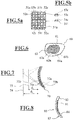
- the Figure 6 shows a first embodiment of a spectacle lens 60 in plan view from the object side in the form of a schematic diagram.
- the visible surface is identified with the reference symbol 63.
- the exemplary embodiment has a region 61 which is designed in the shape according to the invention. It is a nested arrangement of two sub-grids in the manner of a "checkerboard" pattern, as seen in the Figure 1 is shown.
- Volume elements of the first sub-grid are exemplarily marked with the reference symbols 61a, 61b and volume elements of the second sub-grid are exemplarily marked with the reference symbols 62a, 62b.
- the area 61 is designed for sharp vision at two different object distances.
- the Figure 7 shows a second exemplary embodiment of a spectacle lens 70 in cross section (schematic diagram).
- the entire spectacle lens 70 consists of a first volume element group with a plurality of first volume elements 71a, 71b, which are arranged in the manner of grid points of a geometric grid to form a first partial grid, and of a second volume element group with a plurality of second volume elements 72a, 72b, which are arranged in the manner of grid points of a geometric grid to form a second partial grid.
- the execution corresponds in principle to that in Figure 4 shown arrangement of the two sub-grids to each other.
- the first volume elements 71a, 71b together form a first part of the spectacle lens which has the dioptric power for seeing for a first object distance.
- the second volume elements together form a second part of the spectacle lens which has the dioptric power for vision for a second object distance different from the first object distance. Since the first volume element group and the second volume element group prevail, they form a macroscopically common see-through area which, on the one hand, enables sharp vision of an object arranged in the first object distance d 1 and sharp vision of an object arranged in a second object distance d 2 .
- the corresponding focal planes are identified in the drawing with the reference symbols 73 and 74.
- the Figure 8 shows a third exemplary embodiment of a spectacle lens 80 in cross section (as a basic sketch).
- the structure 81 according to the invention is applied to the rear side (eye side) 84 of a transparent carrier 85 in the form of a buried structure.
- the front side (object side) 83 of the spectacle lens 80 can be designed spherical, torical, rotationally symmetrical, aspherical or aspherical (for example as a free-form surface).
- a fourth exemplary embodiment of a spectacle lens 90 can be seen in cross section (in the form of a schematic diagram).
- the structure 91 according to the invention is applied to the front side (object side) 93 of a transparent carrier 95 in the form of a buried structure.
- the rear side (side of the eye) 94 of the spectacle lens 90 can be designed spherical, toric or aspherical (eg as a free-form surface).
- coatings such as e.g. Hard layers, anti-reflective coatings, non-stick coatings and the like can be applied.
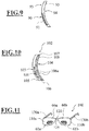
- the Figure 10 shows, in the form of a schematic diagram, a fifth exemplary embodiment of a spectacle lens 102 according to the invention in cross section.
- the structure 101 according to the invention is applied to part of the rear side (eye side) 104 of a transparent carrier 105 in the form of a buried structure.
- the front side (side of the eye) 103 of the spectacle lens 102 can be designed spherical, toric or aspherical (eg as a free-form surface).
- a smoothing hard layer 106 which also fills the spaces 106a of the buried structure, an adhesion-promoting layer 107 and an anti-reflective coating 108 consisting of a plurality of individual layers are applied to the buried structure 101.
- structures 101 can also be applied to the carrier 105 both at the front and at the rear.
- FIG Figure 11 An exemplary embodiment of a pair of spectacles 100 with spectacle lenses 110a, 110b according to the invention can be found in FIG Figure 11 .
- the spectacles 100 comprise a spectacle frame 120, of which the bridge 125 and the two temples 130a, 130b are shown.
- Each spectacle lens 110a, 110b comprises a carrier 66a, 66b, each of which has a structure 61a, 61b according to the invention in the Figure 6 type shown. All components of the glasses can be produced with the help of a 3D printing process.
- the idea of the invention consists in using a manufacturing process that allows the control of the dioptric power of the spectacle lens, in particular the control of the refractive index for each individual volume element and the relative orientation of the surfaces of the volume elements (e.g. PolyJet printing), a three-dimensional structure in which the far and near areas are nested in one another.
- the change from one focus to the next can be gradual or sudden.
- small transition zones with similar properties as the progression channel in conventional varifocal lenses and the associated optical properties result.
- the change in properties can occur suddenly by changing the material or changing the orientation of the optical surface.
- the surface elements can be arranged in any way. For example, but not limited to, a chessboard, hexagons or concentric circles.
- the discontinuous surfaces can be designed as buried structures in two materials, which on the one hand makes the subsequent hard and anti-reflective coating much easier (conventional smoothing hard-coating systems can be used), on the other hand, the discontinuities of the surfaces do not form any cavities for later Accumulation of dirt on the surface.
- the hard coating must be adjusted in such a way that the edges of the optically effective surfaces are not or no longer smoothed as absolutely unavoidable. If the change in the refractive power is operated via the refractive index of the material, the possible embodiments can be found in the patent applications WO 2015/014381 A1 and WO 2014/179780 A1 . If the desired effect difference (addition) between two or more surface elements is not sufficient to achieve the desired effect when using only one of the two principles (material variation vs. discontinuous surface), the two approaches can be combined with one another.
- the lens should continue to have the usual finishing, hard and AR coating.
- a precondition is the availability of a carrier of the structure according to the invention that is preformed to match the surface of the spectacle lens.
Description
Die Erfindung betrifft Brillengläser nach dem Oberbegriff des Patentanspruchs 1.The invention relates to spectacle lenses according to the preamble of claim 1.
Brillengläser sind aus dem Stand der Technik in vielen Variationen bekannt. Es gibt Brillengläser ohne nominelle dioptrische Wirkung und Korrektions-Brillengläser, also Brillengläser mit dioptrischer Wirkung. Dioptrische Wirkung ist der Sammelbegriff für die fokussierende und die prismatische Wirkung eines Brillenglases.Spectacle lenses are known in many variations from the prior art. There are lenses without nominal dioptric power and corrective lenses, i.e. lenses with dioptric power. Dioptric power is the collective term for the focusing and prismatic power of a spectacle lens.
Bei Korrektions-Brillengläsern unterscheidet man zwischen Einstärken-Brillengläsern und Multifokal-Brillengläsern. Ein Einstärken-Brillenglas ist ein Brillenglas, bei dem von der Konstruktion her nur eine dioptrische Wirkung vorhanden ist. Ein Mehrstärken-Brillenglas ist ein Brillenglas, bei dem von der Konstruktion her zwei oder mehr sichtbar verschiedene Teile mit unterschiedlichen fokussierenden Wirkungen vorhanden sind. Von Bedeutung sind insbesondere Zweistärken- oder Bifokal-Brillengläser, nämlich Mehrstärken-Brillengläser mit zwei Teilen, üblicherweise für das Sehen in die Ferne und die Nähe, sowie Gleitsicht-Brillengläser, nämlich Brillengläser mit mindestens einer Gleitsichtfläche und einer zunehmenden (positiven) Wirkung, wenn der Brillenträger nach unten blickt. Selten sind degressive Brillengläser, also solche mit mindestens einer Gleitsichtfläche und einer abnehmenden Wirkung (d. h. einer Abschwächung der Wirkung), wenn der Brillenträger nach unten blickt.When it comes to prescription lenses, a distinction is made between single vision lenses and multifocal lenses. A single vision lens is a lens that has only a dioptric power due to its construction. A multifocal spectacle lens is a spectacle lens in which two or more visibly different parts with different focusing effects are present. Two-strength or bifocal lenses are particularly important, namely multifocal lenses with two parts, usually for far and near vision, and varifocal lenses, namely lenses with at least one varifocal surface and an increasing (positive) effect, if the wearer of glasses looks down. Degressive spectacle lenses, i.e. those with at least one varifocal surface and a diminishing power (i.e. a weakening of the power) when the spectacle wearer looks down, are rare.
Welche Form das Brillenglas erhalten muss, um die gewünschte optische Korrektur zu erhalten, wird maßgeblich von dessen Werkstoff bestimmt. Wichtigster Parameter ist hierbei der Brechungsindex des Werkstoffs. Während in der Vergangenheit Brillengläser vorwiegend aus mineralischen Gläsern, insbesondere Krongläsern (Abbe-Zahl > 55) und Flintgläsern (Abbe-Zahl < 50) hergestellt wurden, sind mittlerweile Brillengläser aus einer Vielzahl an organischen Materialien erhältlich. Derartige Grundmaterialien für organische Brillengläser werden u.a. unter den Handelsbezeichnungen CR 39, MR 8, MR 7, CR 330 sowie MR 174 angeboten. Eine Auswahl solcher Grundmaterialien findet sich auch in der Veröffentlichungsschrift
Derzeit werden eine große Anzahl an organischen Brillenglas-Halbfertigfabrikaten oder Brillenglas-Fertigfabrikaten mit sphärischen, rotationssymmetrisch asphärischen oder progressiven Vorderflächen in Massenfertigung in Urformen mit Vorder- und Rückflächenformschalen, die mittels eines Dichtrings einen Hohlraum bildend voneinander beabstandet sind, abgegossen, wie dies z.B. in den Dokumenten
Halbfertigfabrikate oder Fertigfabrikate für Brillengläser aus Polycarbonat werden im Allgemeinen in Metallformen mittels Spritzgusstechnik erzeugt. Dieses Herstellverfahren ist z.B. in der
Mineralische Brillengläser werden regelmäßig durch maschinelle mechanisch abrasive Bearbeitung eines Rohlings erzeugt.Mineral spectacle lenses are regularly produced by mechanically abrasive machining of a blank.
Die vorstehend beschriebenen Halbfertig- oder Fertigfabrikate werden häufig einem oder mehreren Veredelungsprozessen unterzogen. Insbesondere werden ein- oder beidseitig Funktionsschichten appliziert. Derartige Funktionsschichten sind Schichten, die die Brillengläser mit vorbestimmten und für den Brillenträger vorteilhaften Eigenschaften ausstatten, die die Brillengläser allein aufgrund der Eigenschaften des Grund- oder Trägermaterials, auf das die Funktionsschichten ggf. appliziert werden, und der Formgebung nicht hätten. Derartige vorteilhafte Eigenschaften sind neben optischen Eigenschaften wie z.B. Entspiegelung, Verspiegelung, Lichtpolarisierung, Färbung, Selbsttönung usw. auch mechanische Eigenschaften wie Härtung, Verminderung des Anhaftens von Schmutz oder des Beschlagens usw. und/oder elektrische Eigenschaften wie Abschirmung von elektromagnetischer Strahlung, Leitung von elektrischem Strom usw. und/oder andere physikalische oder chemische Eigenschaften. Beispiele für Funktionsbeschichtungen entnimmt man z.B. den Dokumenten
Auftragsspezifische Rezeptbrillengläser, d.h. insbesondere individualisierte Einstärken- und Mehrstärkengläser, deren optische Eigenschaften wenigstens teilweise nicht vorauswählbar standardisiert sind, sondern in Bezug auf deren Maß und/oder deren Anordnung auf dem Brillenglas auf den Benutzer angepasst individuell berechnet und gefertigt werden, und im Besonderen Gleitsicht- bzw. Progressivgläser werden durch mechanische, insbesondere deformierende und/oder abrasive, Verfahren in ihre finale Form gebracht. Hierbei können die Außenformen rund, oval oder willkürlich, sogenannte Freiformen beschreibend, ausgebildet sein.Order-specific prescription glasses, i.e. In particular, individualized single-vision and multifocal lenses, the optical properties of which are at least partially not standardized in advance, but are individually calculated and manufactured in relation to their dimensions and / or their arrangement on the spectacle lens, and in particular varifocal or progressive lenses brought into their final shape by mechanical, in particular deforming and / or abrasive processes. Here, the outer shapes can be round, oval or arbitrary, describing so-called free shapes.
Hochwertige Brillengläser werden heutzutage mit individuell angepasster dioptrischer Wirkung in einer dafür ausgelegten Rezeptfertigungsstätte, einem sogenannten Rx-Lab (Rx ist das Kürzel für Rezept), mittels subtraktiver Fertigungsmethoden aus Halbfabrikaten (abgekürzt HF) hergestellt. Das fertige Produkt wird durch zwei optische Oberflächen definiert, die je nach Stärke bzw. dioptrischer Wirkung, Material und Regulatorik unterschiedliche Abstände zueinander haben. Die beiden optischen Oberflächen sind als Folge des im Allgemeinen verwendeten Freiform-Fertigungsverfahrens stetig. Die Ausnahmen von dieser Regel, die eingelassenen Nahbereichsflächen bei Bifokal- und Trifokalgläsern, müssen bei Kunststoffgläsern bereits im Abgießprozess auf der Vorderseite eingebracht werden. Es gibt auch entsprechende Brillengläser mit rückseitig abstehend abgeformten Nahbereichsflächen.Nowadays, high-quality spectacle lenses with individually adapted dioptric power are manufactured from semi-finished products (abbreviated HF) in a prescription production facility designed for this purpose, a so-called Rx-Lab (Rx is the abbreviation for prescription) using subtractive production methods. The finished product is defined by two optical surfaces with different distances depending on the strength or dioptric power, material and regulations have to each other. The two optical surfaces are continuous as a result of the free-form manufacturing process generally used. The exceptions to this rule, the embedded close-up areas in bifocal and trifocal lenses, must be incorporated on the front of plastic lenses during the casting process. There are also corresponding spectacle lenses with near-range surfaces that protrude from the back.
Bei heutigen Brillengläsern mit mehreren Stärken bzw. dioptrischen Wirkungen, nämlich bei Bifokalgläsern, Trifokalgläsern und Multifokalgläsern, insbesondere Gleitsichtgläsern sind der Nah- und Fernbereich räumlich getrennt. Dies stört insbesondere immer dann, wenn der Brillenträger im Nahbereich, aber hoch vor dem Kopf bzw. im Fernbereich durch den unteren Teil der Brille sehen möchte.In today's spectacle lenses with several strengths or dioptric effects, namely with bifocal lenses, trifocal lenses and multifocal lenses, in particular varifocal lenses, the near and far areas are spatially separated. This is particularly annoying when the spectacle wearer wants to see through the lower part of the glasses in the close range but high in front of the head or in the far range.
Der derzeitige Markt für Brillenfassungen ist in Hinsicht auf die Designfreiheit sehr davon abhängig, welche Formen und Größen an Brillengläsern von deren Produzenten geliefert werden können. Entscheidend sind hier vor allem der Durchmesser und die Dicke der Halbfabrikate, die festlegen, ob ein Brillenglas noch gefertigt werden kann, weil es in das Halbfabrikat hineinpasst oder eben nicht. Hier können die Begrenzungen der herkömmlichen Massenfertigung deutlich ausgeweitet werden, wenn das Abgießen der Halbfabrikate in vorgegebenen Formschalen aufgegeben wird.In terms of design freedom, the current market for spectacle frames is very dependent on the shapes and sizes of spectacle lenses that can be supplied by their manufacturers. The diameter and thickness of the semifinished product are decisive here, which determine whether a spectacle lens can still be manufactured because it fits into the semifinished product or not. Here, the limitations of conventional mass production can be significantly expanded if the pouring of the semi-finished products in given mold shells is abandoned.
Bei den derzeitig in der Massenfertigung hergestellten Brillengläsern ist der Brechungsindex unabhängig vom Ort einheitlich und konstant, so dass bei starken Korrektionen die Dicke des Brillenglases zum Rand hin (bei Myopen bzw. Kurzsichtigen) oder zur Mitte hin (bei Hyperopen bzw. Weitsichtigen) deutlich zunimmt. Dies ist insbesondere im ersten Fall kosmetisch unattraktiv, weil die große Randdicke auffällig ist.In the case of spectacle lenses currently mass-produced, the refractive index is uniform and constant regardless of location, so that with strong corrections the thickness of the spectacle lens increases significantly towards the edge (for myopes or nearsighted people) or towards the center (for hyperopes or farsighted people) . This is cosmetically unattractive, especially in the first case, because the large edge thickness is noticeable.
Die nachfolgend angegebenen inhärenten Eigenschaften von massengefertigten Brillengläsern, die selbst bei hochwertigen Produkten vorhanden sind, werden als störend empfunden:
- 1. die makroskopische räumliche Trennung von Nah- und Fernbereich
- 2. die beim gleitenden Übergang vom Fern- in den Nahbereich bei Gleitsichtgläsern nach dem Satz von Minkwitz unvermeidbar auftretenden astigmatischen Verzerrungen zum Rand hin
- 3. die nur mit erheblichem Aufwand realisierbaren unstetigen und/oder unstetig differenzierbaren optischen Oberflächen
- 4. die kosmetisch unattraktive, da sichtbare Kante zwischen Grundglas und Segment bei nichtprogressiven Multifokalgläsern, wie z.B. bei Bifokal- oder Trifokalgläsern
- 5. die unästhetische, da sichtbare große Randdicke bei Brillengläsern mit starker dioptrischer Wirkung; insbesondere hohe prismatische Werte führen bei myopen Menschen zu einem dicken Rand des Brillenglases
- 6. die Einschränkung der Herstellbarkeit von Korrektionsbrillen im Falle von als ästhetisch empfundenen Formvorgaben an die Brillenglasvorderfläche und/oder die Brillenfassung; heutige Brillengläser sind durch die Herstellungsart und die Form der Fassungen ganz erheblich eingeschränkt in Hinsicht auf die äußere Form, daraus folgt eine entsprechend geringe Designfreiheit. Produkte wie Nike Vaporwing Elite sind im Rahmen der derzeit bestehenden Restriktionen praktisch nicht mit optischer Stärke sondern nur als 0 dpt Sonnenbrillen herstellbar.
- 1. the macroscopic spatial separation of near and far range
- 2. The inevitable astigmatic distortions towards the edge that occur during the smooth transition from the far to the near range in varifocals according to Minkwitz's theorem
- 3. the discontinuous and / or discontinuously differentiable optical surfaces that can only be realized with considerable effort
- 4. the cosmetically unattractive, since visible edge between the base lens and segment in non-progressive multifocal lenses, such as bifocal or trifocal lenses
- 5. the unaesthetic, because it is visible, large edge thickness in spectacle lenses with a strong dioptric power; In particular, high prismatic values lead to a thick rim of the spectacle lens in myopic people
- 6. the restriction of the manufacturability of corrective glasses in the case of aesthetically perceived shape specifications for the front surface of the lens and / or the frame; Today's spectacle lenses are considerably restricted in terms of the external shape due to the method of manufacture and the shape of the frames, which results in a correspondingly low degree of design freedom. Products such as Nike Vaporwing Elite can practically not be manufactured with optical strength within the framework of the currently existing restrictions, but only as 0 D sunglasses.
Aus dem Stand der Technik sind unterschiedliche Ansätze bekannt, Brillengläser im Hinblick auf die oben als störend empfundenen Eigenschaften zu verbessern. Insbesondere ist in diesem Zusammenhang bekannt, dass insbesondere sogenannte digitale Fabrikatoren Fertigungsmöglichkeiten für nahezu beliebige Strukturen bieten, die mit den klassischen abrasiven Verfahren nicht oder nur schwer realisierbar sind. Innerhalb der Maschinenklasse der digitalen Fabrikatoren stellen die 3D-Drucker die wichtigste Teilklasse der additiven, also anhäufenden, aufbauenden Fabrikatoren dar. Die wichtigsten Techniken des 3D-Druckens sind das selektive Laserschmelzen (SLM) und das Elektronenstrahlschmelzen für Metalle und das selektive Lasersintern (SLS) für Polymere, Keramik und Metalle, die Stereolithografie (SLA) und das Digital Light Processing für flüssige Kunstharze und das Multijet- oder Polyjet-Modeling (z.B. Tintenstrahldrucken) sowie das Fused Deposition Modeling (FDM) für Kunststoffe und teilweise Kunstharze. Nachfolgend werden einige Ansätze skizziert, bei denen mit Hilfe additiver Methoden Transmissionsoptiken erzeugt werden.Different approaches are known from the prior art for improving spectacle lenses with regard to the properties that are perceived as disturbing above. In particular, it is known in this context that what are known as digital factories in particular offer manufacturing options for almost any structure that cannot or can only be implemented with difficulty using classic abrasive processes. Within the machine class of digital fabricators, 3D printers represent the most important sub-class of additive, i.e. accumulating, building fabricators. The most important techniques of 3D printing are selective laser melting (SLM) and electron beam melting for metals and selective laser sintering (SLS) for polymers, ceramics and metals, stereolithography (SLA) and digital light processing for liquid synthetic resins and multijet or polyjet modeling (e.g. inkjet printing) as well as fused deposition modeling (FDM) for plastics and sometimes synthetic resins. In the following, some approaches are outlined in which transmission optics are generated with the help of additive methods.
Die
Ein optisches Element, bei dem auf ein transparentes Substrat mit Hilfe eines 3D-Druckverfahrens, nämlich insbesondere mit einem "Drop on Demand" Tintenstrahldrucker (DOD inkjet printer) lichtleitende Strukturen und insbesondere ein optisches Prisma aufgebracht ist, sowie ein Verfahren zu dessen Herstellung ist auch in der
Die
Die
Auch die
Weiterhin beschreibt die
Obwohl sich mit verschiedenen Methoden Brillengläser herstellen lassen, die dem ästhetischen Empfinden vieler Menschen Rechnung tragen, besteht weiterer Verbesserungsbedarf.Although different methods can be used to manufacture spectacle lenses that take into account the aesthetic perception of many people, there is still room for improvement.
Die
Die
Die
Die Aufgabe der Erfindung besteht darin, ein Verfahren zum Herstellen eines Brillenglases bereitzustellen, bei dem wenigstens einer der oben als störend empfundenen Faktoren herkömmlicher Brillengläser verbessert wird.The object of the invention is to provide a method for producing a spectacle lens in which at least one of the factors of conventional spectacle lenses that are perceived as disturbing above is improved.
Die Aufgabe der Erfindung besteht weiter darin, ein Brillenglas bereitzustellen, bei dem wenigstens einer der oben als störend empfundenen Faktoren herkömmlicher Brillengläser verbessert wird.The object of the invention is furthermore to provide a spectacle lens in which at least one of the factors of conventional spectacle lenses that are perceived as disturbing above is improved.
Die verfahrensbezogene Aufgabe wird durch ein Verfahren zum Herstellen eines Brillenglases mit den Merkmalen des Patentanspruchs 1 gelöst. Die produktbezogene Aufgabe wird durch ein Brillenglas gelöst, welches die Merkmale des Patentanspruchs 1 aufweist. Vorteilhafte Ausführungen und Weiterbildungen der Erfindung sind Gegenstand der Unteransprüche.The method-related object is achieved by a method for producing a spectacle lens with the features of claim 1. The product-related task is carried out by a Spectacle lens solved, which has the features of claim 1. Advantageous embodiments and developments of the invention are the subject of the subclaims.
Alle erfindungsgemäßen Varianten haben gemein, dass das jeweilige Brillenglas wenigstens zwei Volumenelementgruppen umfasst, nämlich eine erste Volumenelementgruppe, welche eine Mehrzahl an ersten Volumenelementen umfasst, wobei die Mehrzahl an ersten Volumenelementen in der Art von Gitterpunkten eines geometrischen Gitters ein erstes Teilgitter bildend angeordnet sind, wobei die ersten Volumenelemente zusammen ein erstes Teil des Brillenglases bilden, das die dioptrische Wirkung für das Sehen für einen ersten Objektabstand besitzt, wobei die ersten Volumenelemente aus einem ersten Material bestehen und die zweiten Volumenelemente aus einem zweiten von den ersten Material sich unterscheidenden Material bestehen und wobei ein Übergang zwischen einem der ersten Volumenelemente zu einem angrenzenden der zweiten Volumenelemente durch eine graduelle Änderung des Materials der aneinander grenzenden ersten und zweiten Volumenelemente erfolgt. Das Brillenglas umfasst ferner eine zweite Volumenelementgruppe, welche in entsprechender Weise eine Mehrzahl an zweiten Volumenelementen umfasst, wobei die Mehrzahl an zweiten Volumenelementen in der Art von Gitterpunkten eines geometrischen Gitters ein zweites Teilgitter bildend angeordnet sind und wobei die zweiten Volumenelemente zusammen ein zweites Teil des Brillenglases bilden, das die dioptrische Wirkung für das Sehen für einen zweiten von dem ersten Objektabstand verschiedenen Objektabstand besitzt. Bei allen Varianten des erfindungsgemäßen Brillenglases sind das erste Teilgitter und das zweite Teilgitter sich jeweils durchsetzend ineinander (z.B. verschoben oder versetzt) angeordnet.All variants according to the invention have in common that the respective spectacle lens comprises at least two volume element groups, namely a first volume element group which comprises a plurality of first volume elements, the plurality of first volume elements being arranged in the manner of grid points of a geometric grid forming a first partial grid, wherein the first volume elements together form a first part of the spectacle lens which has the dioptric power for vision for a first object distance, the first volume elements consisting of a first material and the second volume elements consisting of a second material different from the first material, and wherein a transition between one of the first volume elements and an adjoining one of the second volume elements occurs through a gradual change in the material of the adjoining first and second volume elements. The spectacle lens further comprises a second volume element group, which correspondingly comprises a plurality of second volume elements, the plurality of second volume elements being arranged in the manner of grid points of a geometric grid forming a second partial grating and the second volume elements together forming a second part of the spectacle lens form which has the dioptric power for vision for a second object distance different from the first object distance. In all variants of the spectacle lens according to the invention, the first partial grating and the second partial grating are each arranged so as to penetrate one another (e.g. shifted or offset).
Ein Gitter in der Geometrie ist eine lückenlose und überlappungsfreie Partition eines Bereichs des Raumes durch eine Menge von Gitterzellen. Die Gitterzellen werden definiert durch eine Menge von (fiktiven oder imaginären) Gitterpunkten, die untereinander durch eine Menge von (fiktiven oder imaginären) Gitterlinien verbunden sind.A grid in geometry is a gapless and overlap-free partition of an area of space by a set of grid cells. The grid cells are defined by a set of (fictitious or imaginary) grid points that are connected to one another by a set of (fictitious or imaginary) grid lines.
Dass sich das erste und das zweite Teilgitter durchsetzen bedeutet, dass das erste Teilgitter und das zweite Teilgitter einen Raum miteinander gemeinschaftlich haben, ohne ganz zusammenzufallen. Durchsetzend ineinander verschoben bedeutet im Rahmen der vorliegenden Erfindung eine Anordnung in der Art beispielsweise einer Zinkblendestruktur, die sich als Kombination zweier ineinander gestellter kubisch-flächenzentrierter Teilgitter beschreiben lässt, die um 1/4 der Raumdiagonale gegeneinander verschoben angeordnet sind. Umfasst sein sollen auch (einlagige) Schichtgitter, die um ein bestimmtes Maß eines in der Schichtfläche liegenden Vektors gegeneinander verschoben sind. Die beiden ersten und zweiten Teilgitter brauchen auch nicht von identischer Gestalt sein. Entscheidend ist vielmehr, dass die beiden ersten und zweiten Teilgitter keine makroskopische räumliche Trennung der dioptrischen Wirkung für das Sehen bei unterschiedlichen Objektabständen bereitstellen.The fact that the first and the second sub-grid prevail means that the first sub-grid and the second sub-grid share a space with one another without completely collapsing. Assertively shifted within the scope of the present invention means an arrangement in the manner of, for example, a zinc blende structure, which can be described as a combination of two cubic face-centered partial grids placed one inside the other, which are arranged offset from one another by 1/4 of the spatial diagonal. It should also include (single-layer) layer grids that are shifted from one another by a certain amount of a vector lying in the layer area. The two first and second partial grids also do not need to be of identical shape. Rather, it is crucial that the two first and second partial grids do not have any macroscopic spatial separation of the dioptric power for vision provide different object distances.
Das erste Teil des Brillenglases, das die dioptrische Wirkung für das Sehen für einen ersten Objektabstand bereitstellt, kann z.B. dem Nahbereich und das zweite Teil des Brillenglases, das die dioptrische Wirkung für das Sehen für einen zweiten Objektabstand bereitstellt, kann z.B. dem Fernbereich eines herkömmlichen Brillenglases entsprechen. Die erfindungsgemäße Anordnung der ersten und zweiten Teilgitter stellt demnach eine dreidimensionale Struktur bereit, bei der die Fern- und Nahbereiche quasi ineinander verschachtelt vorliegen. Selbstverständlich können der erste Objektabstand auch der gewöhnliche Abstand Auge - Bildschirm und der zweite Objektabstand der gewöhnliche Leseabstand sein. Derartige Brillengläser sind für die Büroarbeit oder dergleichen geeignet.The first part of the spectacle lens that provides the dioptric power for vision for a first object distance can e.g. the near range and the second part of the spectacle lens that provides the dioptric power for vision for a second object distance can e.g. correspond to the far range of a conventional spectacle lens. The arrangement according to the invention of the first and second partial grids accordingly provides a three-dimensional structure in which the far and near areas are more or less nested in one another. Of course, the first object distance can also be the usual eye-screen distance and the second object distance can be the usual reading distance. Such glasses are suitable for office work or the like.
Das erste Teil und das zweite Teil des Brillenglases stellen demnach zusammenfallende Flächenbereiche des Brillenglases dar, durch welche der Brillenträger bei bestimmungsgemäßem Gebrauch blickt. Typische Flächengrößen dieser Bereiche liegen zwischen 0,3 cm2 und 7 cm2, vorzugsweise zwischen 0,5 cm2 und 6 cm2, weiter vorzugsweise zwischen 0,8 cm2 und 5 cm2 und schließlich noch weiter vorzugsweise zwischen 1 cm2 und 4 cm2.The first part and the second part of the spectacle lens accordingly represent coincident surface areas of the spectacle lens through which the spectacle wearer looks when used as intended. Typical surface sizes of these areas are between 0.3 cm 2 and 7 cm 2 , preferably between 0.5 cm 2 and 6 cm 2 , more preferably between 0.8 cm 2 and 5 cm 2 and finally even more preferably between 1 cm 2 and 4 cm 2 .
Das Brillenglas kann sich bei entsprechender Ausführung dadurch auszeichnen, dass
- keine sichtbaren Bifokal- oder Trifokalbereiche vorliegen
- kein Progressionskanal einer Gleitsichtbrille benötigt wird und somit alle damit zusammenhängenden Individualisierungsparameter obsolet werden (Progressionskanallänge, Inset, Fassungsform, Gleitsicht-Profil, Ausgewogenheit der bei konventionellen Gleitsichtgläsern unvermeidbaren Bildfehlerverteilung)
- die Addition (der Unterschied zwischen den Foki) unberührt bleibt, wobei die Anzahl der Foki nur durch die Anzahl der unterschiedlichen, individuell eingestellten Voxel (erste, zweite und ggf. weitere Volumenelementgruppen) begrenzt wird
- unter anderem die folgenden Parameter unberührt bleiben können:
Hornhautscheitelabstand (HSA), Vorneigung und Fassungsscheibenwinkel sofern dies gewünscht ist
- there are no visible bifocal or trifocal areas
- no progression channel of varifocal glasses is required and thus all associated individualization parameters become obsolete (progression channel length, inset, frame shape, varifocal profile, balance of the image error distribution unavoidable with conventional varifocal lenses)
- the addition (the difference between the foci) remains unaffected, the number of foci is only limited by the number of different, individually set voxels (first, second and possibly further volume element groups)
- Among other things, the following parameters can remain unaffected:
Corneal vertex distance (HSA), anterior inclination and frame angle if desired
Unberührt bedeutet, dass diese Parameter wie Addition, Hornhautscheitelabstand, Vorneigung und Fassungsscheibenwinkel beim Design der erfindungsgemäßen Brillengläser genauso berücksichtigt werden, wie bei herkömmlichen Brillengläsern nach dem Stand der Technik.Unaffected means that these parameters such as addition, corneal vertex distance, forward inclination and frame lens angle are taken into account in the design of the spectacle lenses according to the invention in exactly the same way as with conventional spectacle lenses according to the prior art.
Neben diesen naheliegenden Anwendungen im Bereich der Gleitsicht- und Multifokalgläser bietet die beschriebene Ausführung Ansätze die kosmetischen Probleme von Einstärkengläsern abzumildern. Dazu besteht die Möglichkeit, die optische Korrektur nicht mehr ausschließlich über die relative Lage der optischen Flächen bei Berücksichtigung eines konstanten Brechungsindices einzubringen, wie dies bei herkömmlichen Brillengläsern der oben zum Stand der Technik beschriebenen Art der Fall ist.In addition to these obvious applications in the field of varifocal and multifocal lenses, the embodiment described offers approaches to alleviate the cosmetic problems of single vision lenses. For this purpose, there is the possibility of introducing the optical correction no longer exclusively via the relative position of the optical surfaces, taking into account a constant refractive index, as is the case with conventional spectacle lenses of the type described above in relation to the prior art.
Hergestellt werden die Volumenelementgruppen nach der Erfindung mit Hilfe eines additiven Fertigungsverfahrens. Das Verfahren zum Herstellen eines Brillenglases nach der Erfindung umfasst konkret die folgenden Verfahrensschritte:
- additives Fertigen einer ersten Volumenelementgruppe, wobei die erste Volumenelementgruppe eine Mehrzahl an ersten Volumenelementen umfasst, wobei die Mehrzahl an ersten Volumenelementen in der Art von Gitterpunkten eines geometrischen Gitters ein erstes Teilgitter bildend angeordnet sind, wobei die ersten Volumenelemente zusammen ein erstes Teil des Brillenglases bilden, das die dioptrische Wirkung für das Sehen für einen ersten Objektabstand besitzt
- additives Fertigen einer zweiten Volumenelementgruppe, wobei die zweite Volumenelementgruppe eine Mehrzahl an zweiten Volumenelementen umfasst, wobei die Mehrzahl an zweiten Volumenelementen in der Art von Gitterpunkten eines geometrischen Gitters ein zweites Teilgitter bildend angeordnet sind, wobei die zweiten Volumenelemente zusammen ein zweites Teil des Brillenglases bilden, das die dioptrische Wirkung für das Sehen für einen zweiten von dem ersten Objektabstand verschiedenen Objektabstand besitzt.
- additive manufacturing of a first volume element group, wherein the first volume element group comprises a plurality of first volume elements, wherein the plurality of first volume elements are arranged in the manner of grid points of a geometric grid forming a first partial grid, wherein the first volume elements together form a first part of the spectacle lens, which has the dioptric power for vision for a first object distance
- additive manufacturing of a second volume element group, wherein the second volume element group comprises a plurality of second volume elements, wherein the plurality of second volume elements are arranged in the manner of grid points of a geometric grid forming a second partial grid, the second volume elements together forming a second part of the spectacle lens, which has the dioptric power for vision for a second object distance different from the first object distance.
Das Verfahren ist dadurch gekennzeichnet, dass das erste Teilgitter und das zweite Teilgitter beim additiven Fertigen sich jeweils durchsetzend ineinander (z.B. verschoben oder versetzt) angeordnet werden.The method is characterized in that the first sub-grid and the second sub-grid are arranged in each case penetrating one another (e.g. shifted or offset) during additive manufacturing.
Die Verfahrensschritte additives Fertigen der ersten Volumenelementgruppe und additives Fertigen der zweiten Volumenelementgruppe sollen nicht zwingend erfordern, dass zuerst die erste Volumenelementgruppe und dann die zweite Volumenelementgruppe fertiggestellt werden.The method steps additive manufacturing of the first volume element group and additive manufacturing of the second volume element group should not necessarily require that the first volume element group and then the second volume element group be completed first.
Vielmehr können zunächst ein oder mehrere Volumenelemente der ersten Volumenelementgruppe additiv erzeugt werden, dann wiederum ein oder mehrere Volumenelemente der zweiten Volumenelementgruppe, dann wieder ein oder mehrere Volumenelemente der ersten Volumenelementgruppe usw. bis die beiden Volumenelementgruppen in der Anordnung entsprechend zweier sich jeweils durchsetzend ineinander verschobenen Teilgitter fertiggestellt sind.Rather, one or more volume elements of the first volume element group can first be generated additively, then in turn one or more volume elements of the second volume element group, then again one or more volume elements of the first volume element group, etc. are completed.
Additive Fertigung - englisch: Additive Manufacturing (AM) bzw. generative Fertigungsverfahren - ist eine umfassende Bezeichnung für die bisher häufig als Rapid Prototyping bezeichneten Verfahren zur schnellen und kostengünstigen Fertigung von Modellen, Mustern, Prototypen, Werkzeugen und Endprodukten. Diese Fertigung erfolgt direkt auf der Basis von rechnerinternen Datenmodellen aus formlosem (z.B. Flüssigkeiten, Pulver u. ä.) oder formneutralem (band-, drahtförmig) Material mittels chemischer und/oder physikalischer Prozesse. Obwohl es sich um urformende Verfahren handelt, sind für ein konkretes Erzeugnis keine speziellen Werkzeuge erforderlich, die die jeweilige Geometrie des Werkstückes gespeichert haben (zum Beispiel Gussformen). Den aktuellen Stand der Technik vermittelt der VDI Statusreport AM 2014. Eine Übersicht über aktuelle 3D-Druckverfahren gibt https://3druck.com/grundkurs-3d-drucker/teil-2-uebersicht-der-aktuellen-3d-druckverfahren-462146/, heruntergeladen am 13.7.2016.Additive Manufacturing - English: Additive Manufacturing (AM) or generative manufacturing process - is a comprehensive term for the processes, which have so far often been referred to as rapid prototyping, for the fast and cost-effective production of models, samples, prototypes, tools and end products. This production takes place directly on the basis of computer-internal data models from informal (e.g. liquids, powder, etc.) or form-neutral (ribbon, wire-like) material using chemical and / or physical processes. Although this is a primary forming process, no special tools are required for a specific product that have saved the respective geometry of the workpiece (e.g. casting molds). The VDI Status Report AM 2014 provides the current state of the art. An overview of current 3D printing processes is given at https://3druck.com/grundkurs-3d-drucker/teil-2-uebersicht-der-aktuellen-3d-druckverfahren-462146/ , downloaded on 7/13/2016.
Als besonders geeignet hat sich die
Der 3D-Drucker der Bezeichnung Stratasys (Objet) Eden 260 V ist insbesondere für den erfindungsgemäßen Anwendungsfall geeignet. Die oben in der Beschreibungseinleitung angegebenen und insbesondere in den Dokumenten
Die ersten und zweiten Volumenelemente können auch wie oben beschrieben aus einer mit Nanopartikeln versetzten organischen Matrix bestehen. Die organische Matrix kann z.B. aus Di(ethylenglykol)diacrylat, Neopentylglykoldiacrylat, Hexandioldiacrylat, Bisphenol-A-Novolak Epoxy Harz (SU8), 2-Hydroxyethylmethacrylat (HEMA), Polyacrylat, Polymethacrylat, Polymethylmethacrylat (PMMA), Styren und Poly[(2, 3,4,4,5,5-Hexafluorotetrahydrofuran-2, 3-diyl)(1, 1,2,2-tetrafluoroethylen)] (CYTOP) bestehen. Mögliche Materialien für die Nanopartikel sind z.B. ZnS, ZrO2, ZnO, BeO, AlN, TiO2 und SiO2.As described above, the first and second volume elements can also consist of an organic matrix mixed with nanoparticles. The organic matrix can, for example, consist of di (ethylene glycol) diacrylate, neopentyl glycol diacrylate, hexanediol diacrylate, bisphenol-A novolak epoxy resin (SU8), 2-hydroxyethyl methacrylate (HEMA), polyacrylate, polymethacrylate, polymethyl methacrylate (PMMA), styrene and poly [(2, 3,4,4,5,5-hexafluorotetrahydrofuran-2, 3-diyl) (1, 1,2,2-tetrafluoroethylene)] (CYTOP). Possible materials for the nanoparticles are, for example, ZnS, ZrO 2 , ZnO, BeO, AlN, TiO 2 and SiO 2 .
Die eingangs gestellte verfahrensspezifische Aufgabe wird durch ein derartiges Verfahren zum Herstellen eines Brillenglases vollumfänglich gelöst. Hiermit wird daraufhingewiesen, dass die Erfindung nicht nur auf eine durchsetzende Anordnung zweier Teilgitter beschränkt ist. Vielmehr können auch mehr als zwei Teilgitter für entsprechende sich unterscheidende Objektabstände realisiert werden. Es hat sich aber als vorteilhaft herausgestellt, die Zahl der unterschiedlichen Teilgitter auf nicht mehr als 5, vorzugsweise nicht mehr als vier oder auch nicht mehr als 3 zu beschränken, weil das menschliche Gehirn eine scharfe Wahrnehmung sonst nicht oder nur schwer erlaubt.The method-specific problem set out at the beginning is fully achieved by such a method for producing a spectacle lens. It is hereby pointed out that the invention is not limited to a penetrating arrangement of two partial grids. Rather, more than two partial grids can also be implemented for correspondingly differing object distances. However, it has been found to be advantageous to limit the number of different sub-grids to no more than 5, preferably no more than four or also no more than 3, because the human brain otherwise does not allow sharp perception or only with difficulty.
Die oben angegebene produktbezogene Aufgabe kann durch eine der nachfolgend angegebenen Varianten gelöst werden: Ausgangsprodukt ist stets ein Brillenglas mit den nachfolgend angegebenen Merkmalen:
Das erfindungsgemäße Brillenglas umfasst eine erste Volumenelementgruppe, welche eine Mehrzahl an ersten Volumenelementen umfasst, wobei die Mehrzahl an ersten Volumenelementen in der Art von Gitterpunkten eines geometrischen Gitters ein erstes Teilgitter bildend angeordnet sind und wobei die ersten Volumenelemente zusammen ein erstes Teil des Brillenglases bilden, das die dioptrische Wirkung für das Sehen für einen ersten Objektabstand besitzt. Das Brillenglas umfasst ferner eine zweite Volumenelementgruppe, welche in entsprechender Weise eine Mehrzahl an zweiten Volumenelementen umfasst, wobei die Mehrzahl an zweiten Volumenelementen in der Art von Gitterpunkten eines geometrischen Gitters ein zweites Teilgitter bildend angeordnet sind und wobei die zweiten Volumenelemente zusammen ein zweites Teil des Brillenglases bilden, das die dioptrische Wirkung für das Sehen für einen zweiten von dem ersten Objektabstand verschiedenen Objektabstand besitzt. Das erste Teilgitter und das zweite Teilgitter sind sich jeweils durchsetzend ineinander (z.B. verschoben oder versetzt) angeordnet.The product-related task specified above can be achieved by one of the variants specified below: The starting product is always a spectacle lens with the features specified below:
The spectacle lens according to the invention comprises a first volume element group which comprises a plurality of first volume elements, wherein the plurality of first volume elements are arranged in the manner of grid points of a geometric grid forming a first partial grating and wherein the first volume elements together form a first part of the spectacle lens which possesses the dioptric power for vision for a first object distance. The spectacle lens further comprises a second volume element group, which correspondingly comprises a plurality of second volume elements, the plurality of second volume elements being arranged in the manner of grid points of a geometric grid forming a second partial grating and wherein the second volume elements together form a second part of the spectacle lens form which has the dioptric power for vision for a second object distance different from the first object distance. The first sub-grid and the second sub-grid are each arranged to penetrate one another (for example shifted or offset).
Ein erstes Beispiel besteht darin, dass das erste Teilgitter dreidimensional ausgebildet ist und dass das zweite Teilgitter dreidimensional ausgebildet ist. Durch die dreidimensionale Ausgestaltung beider Teilgitter ergibt sich eine mit der Zahl der Schichten zunehmende Wechselwirkung zwischen den ersten und zweiten Teilen, die für scharfes Sehen in unterschiedlichen Objektabständen ausgelegt sein sollen. Details werden nachfolgend im Zusammenhang mit der Beschreibung zur
Das Brillenglas nach der Erfindung geht von folgender Konstellationen aus:
- (i) die ersten Volumenelemente bestehen aus einem ersten Material und die zweiten Volumenelemente bestehen aus einem zweiten von dem ersten Material sich unterscheidenden Material,
- (i) the first volume elements consist of a first material and the second volume elements consist of a second material different from the first material,
Generell kann eine glättende Hartstoff-Beschichtung angeordnet sein. Unter einer glättenden Hartstoff-Beschichtung versteht man eine Schicht, die die Oberflächenrauheit und Oberflächenstrukturen des Brillenglassubstrates mindert.In general, a smooth hard material coating can be arranged. A smooth hard material coating is a layer that reduces the surface roughness and surface structure of the lens substrate.
Das Brillenglas weist mit dieser glättenden Hartstoff-Beschichtung bevorzugt eine Oberflächenrauigkeit Ra von < 10 nm auf. Weiter bevorzugt liegt die Oberflächenrauigkeit Ra des Brillenglases über alle optischen Flächen jeweils in einem Bereich von 1,0 nm bis 8,0 nm, besonders bevorzugt in einem Bereich von 3,0 nm bis 7,0 nm und ganz besonders bevorzugt in einem Bereich von 4,0 nm bis 6,0 nm. Vorstehend genannte Werte für die Oberflächenrauigkeit Ra beziehen sich jeweils auf die Vorderfläche und die Rückfläche des Brillenglases. Die Oberflächenrauigkeit Ra in Bezug auf das fertige Brillenglas wird vorzugsweise mittels Weißlichtinterferometrie, vorzugsweise mit dem Gerät NewView 7100 (Firma Zygo Corporation), bestimmt.With this smoothing hard material coating, the spectacle lens preferably has a surface roughness Ra of <10 nm. The surface roughness Ra of the spectacle lens is more preferably in a range from 1.0 nm to 8.0 nm, particularly preferably in a range from 3.0 nm to 7.0 nm and very particularly preferably in a range of 4.0 nm to 6.0 nm. The above-mentioned values for the surface roughness Ra relate to the front surface and the rear surface of the spectacle lens, respectively. The surface roughness Ra in relation to the finished spectacle lens is preferably determined by means of white light interferometry, preferably with the NewView 7100 device (Zygo Corporation).
Die Zusammensetzung der glättenden Hartstoff-Beschichtung kann wenigstens ein Silanderivat (R4O)Si(OR1)(OR2)(OR3) enthalten, wobei R1, R2, R3, R4 gleich oder verschieden voneinander, substituiert oder nicht substituiert sein können und R1, R2, R3, R4 aus der Gruppe bestehend aus Alkyl, Acyl, Alkylenacyl, Cycloalkyl, Aryl und Alkylenaryl ausgewählt sein kann. Alternativ oder zusätzlich kann die Zusammensetzung der glättenden Hartstoff-Beschichtung wenigstens ein Silanderivat R6R7 3-nSi(OR5)n enthalten, wobei R5 aus der Gruppe bestehend aus Alkyl, Acyl, Alkylenacyl, Cycloalkyl, Aryl und Alkylenaryl ausgewählt sein kann, R5 substituiert oder nicht substituiert sein kann, R6 ein organischer Rest ist, welcher eine Epoxidgruppe umfasst, R7 aus der Gruppe bestehend aus Alkyl, Cycloalkyl, Aryl und Alkenylaryl ausgewählt sein kann, R7 substituiert oder nicht substituiert sein kann. Weitere Beispiele für derartige glättende Hartstoff-Beschichtungen sind zu finden in
Ein zweites Beispiel ist dadurch gekennzeichnet, dass die erste Volumenelementgruppe und die zweite Volumenelementgruppe auf einer Fläche eines Trägers angeordnet sind, welcher einen (räumlichen) Brechungsindexgradienten aufweist. Wie in der Beschreibungseinleitung beschrieben ist, bietet ein Brechungsgradient die Möglichkeit, eine gewünschte dioptrische Wirkung eines Körpers zu erzeugen, die in geringerem Maß von dessen geometrischer Gestalt abhängt. Auf diese Weise ist es möglich, dass das Brillenglas insgesamt dünner ausgeführt sein kann als wenn ein Träger mit räumlich konstantem Brechungsindex verwendet würde. Die Dicke des Trägers beträgt in einem Bereich, auf dem die erste Volumenelementgruppe und die zweite Volumenelementgruppe angeordnet sind, vorzugsweise zwischen 0,1 und 5 mm, weiter vorzugsweise zwischen 0,5 und 3 mm, höchst vorzugsweise zwischen 1 und 2 mm.A second example is characterized in that the first volume element group and the second volume element group are arranged on a surface of a carrier, which has a (spatial) refractive index gradient. As described in the introduction to the description, a refraction gradient offers the possibility of generating a desired dioptric power of a body, which depends to a lesser extent on its geometric shape. In this way it is possible for the spectacle lens to be made thinner overall than if a carrier with a spatially constant refractive index were used. The thickness of the carrier in an area on which the first volume element group and the second volume element group are arranged is preferably between 0.1 and 5 mm, more preferably between 0.5 and 3 mm, most preferably between 1 and 2 mm.
Die eingangs gestellte produktbezogene Aufgabe wird durch jede der vorstehend beschriebenen drei Varianten vollumfänglich gelöst.The product-related problem posed at the beginning is fully achieved by each of the three variants described above.
Die vorstehend beschriebenen Beispiele und Erfindung lassen sich auch in beliebiger Weise kombinieren, wie beispielhaft im Nachfolgenden im Detail ausgeführt ist.The examples and the invention described above can also be combined in any desired manner, as is exemplified in detail below.
Grundsätzlich ist es möglich, dass die ersten und zweiten Volumenelemente aus demselben Material bestehen. Die Bereitstellung unterschiedlicher dioptrischer Wirkungen für das scharfe Sehen bei unterschiedlichen Objektabständen wird dann durch die jeweilige Oberflächengeometrie der einzelnen ersten und zweiten Volumenelemente und/oder die relative Position und Ausrichtung der einzelnen ersten und zweiten Volumenelemente zueinander und/oder die äußere Geometrie des die beiden ersten und zweiten Teilgitter umfassenden Gitters bestimmt bzw. festgelegt. Der Begriff Oberflächengeometrie umfasst zum einen die Flächengröße als auch die Flächenform, insbesondere auch die lokale Krümmung der Oberfläche des jeweiligen Volumenelements.In principle, it is possible for the first and second volume elements to consist of the same material. The provision of different dioptric effects for sharp vision at different object distances is then determined by the respective surface geometry of the individual first and second volume elements and / or the relative position and orientation of the individual first and second volume elements to one another and / or the external geometry of the two first and second volume elements second sub-grid comprehensive grid determined or set. The term surface geometry includes on the one hand the surface size and the surface shape, in particular also the local curvature of the surface of the respective volume element.
Alternativ ist es entsprechend obigen Ausführungen möglich, dass die ersten Volumenelemente aus einem ersten Material bestehen und dass die zweiten Volumenelemente aus einem zweiten von dem ersten Material sich unterscheidenden Material bestehen. Die Bereitstellung unterschiedlicher dioptrischer Wirkungen für das scharfe Sehen bei unterschiedlichen Objektabständen kann dann nicht nur durch die jeweilige Oberflächengeometrie der einzelnen ersten und zweiten Volumenelemente und/oder die relative Position und Ausrichtung der einzelnen ersten und zweiten Volumenelemente zueinander und/oder die äußere Geometrie des die beiden ersten und zweiten Teilgitter umfassenden Gitters bestimmt bzw. festgelegt werden, sondern auch durch die sich unterscheidenden lichtbrechenden Eigenschaften der jeweiligen ersten und zweiten Volumenelemente. Insbesondere dann, wenn das erste Material einen ersten Brechungsindex aufweist und das zweite Material einen zweiten von dem ersten Brechungsindex unterschiedlichen Brechungsindex aufweist, spielt nicht nur die Orientierung der optisch wirksamen Oberflächen der Volumenelemente eine Rolle, sondern auch deren Brechkraft. Die Einschränkung der Formgebung im Hinblick auf ästhetisches Empfinden entfällt weitgehend oder reduziert sich zumindest im Vergleich zu herkömmlichen Brillengläsern erheblich. Die Verwendung eines additiven Fertigungsverfahrens, insbesondere die Verwendung des MultiJet- oder PolyJet-Printing/Modeling erlaubt die Realisierung unstetiger und/oder unstetig differenzierbarer optischer Oberflächen unter geringem Aufwand. Es entfällt die makroskopische räumliche Trennung von z.B. Nah- und Fernbereich (allgemein: von einem ersten Objektentfernungsbereich und einem zweiten Objektentfernungsbereich) und damit verbunden entfallen die bei Gleitsichtgläsern herkömmlicher Art zum Rand hin auftretenden astigmatischen Verzerrungen.Alternatively, according to the above statements, it is possible that the first volume elements consist of a first material and that the second volume elements consist of a second material that differs from the first material. The provision of different dioptric effects for sharp vision at different object distances can then not only be achieved by the respective surface geometry of the individual first and second volume elements and / or the relative position and orientation of the individual first and second volume elements to one another and / or the external geometry of the two first and second sub-grids comprehensive grating are determined or fixed, but also by the different refractive properties of the respective first and second volume elements. In particular, when the first material has a first refractive index and the second material has a second refractive index different from the first refractive index, not only the orientation of the optically effective surfaces of the volume elements plays a role, but also their refractive power. The restriction of the shape with regard to aesthetic perception is largely eliminated or at least reduced considerably compared to conventional spectacle lenses. The use of an additive manufacturing process, in particular the use of MultiJet or PolyJet printing / modeling, allows the realization of discontinuous and / or discontinuously differentiable optical surfaces with little effort. There is no macroscopic spatial separation of, for example, near and far range (in general: from a first object distance range and a second object distance range) and the astigmatic distortions that occur towards the edge of progressive lenses of conventional type are eliminated.
Verwendet man Materialien unterschiedlicher Brechungsindices zur Realisierung der ersten und zweiten Volumenelemente, ist es möglich, die dioptrischen Wirkungen für die unterschiedlichen Objektentfernungen durch Anordnung der ersten und zweiten Volumenelemente zu erzeugen, dass diese zusammen eine glatte, ggf. sogar ebene Oberfläche ergeben, die bei bestimmungsgemäßem Gebrauch des erfindungsgemäßen Brillenglases bzw. der Brille mit dem erfindungsgemäßen Brillenglas entweder in Richtung des Objekts (d.h. ggf. mit einer Beschichtung versehen die Vorderfläche des Brillenglases bildend) und/oder in Richtung des Auges (d.h. ggf. mit einer Beschichtung versehen die Rückfläche des Brillenglases bildend) ausgerichtet ist. Verwendet man dagegen Materialien gleicher Brechungsindices oder gar identische Materialien zur Realisierung der ersten und zweiten Volumenelemente, so werden die Oberflächen der ersten und zweiten Volumenelemente an den Orten, an denen zwei unterschiedliche Volumenelemente aneinander grenzen, unterschiedlich zueinander orientiert sein, um die erfindungsgemäße Eigenschaft der Bereitstellung einer makroskopischen räumlichen Vereinigung der Bereiche für unterschiedliche Objektentfernungen zu erreichen. Insbesondere kann die Erfindung in diesem Fall dadurch gekennzeichnet sein, dass die ersten Volumenelemente jeweils ein erstes Oberflächenelement aufweisen und dass die zweiten Volumenelemente jeweils ein zweites Oberflächenelement aufweisen und dass jeweils eines der ersten Oberflächenelemente und jeweils eines der zweiten Oberflächenelemente, die aneinander grenzen, winklig zueinander angeordnet sind.If materials with different refractive indices are used to realize the first and second volume elements, it is possible to generate the dioptric effects for the different object distances by arranging the first and second volume elements so that they together result in a smooth, possibly even flat surface, which when used as intended Use of the spectacle lens according to the invention or the glasses with the spectacle lens according to the invention either in the direction of the object (ie if necessary provided with a coating forming the front surface of the spectacle lens) and / or in the direction of the eye (i.e. if the rear surface of the spectacle lens is provided with a coating educational) is aligned. If, on the other hand, materials with the same refractive indices or even identical materials are used to realize the first and second volume elements, the surfaces of the first and second volume elements will be oriented differently to one another at the locations where two different volume elements adjoin one another in order to provide the property of the invention to achieve a macroscopic spatial unification of the areas for different object distances. In particular, the invention can in this case be characterized in that the first volume elements each have a first surface element and that the second volume elements each have a second surface element and that one of the first surface elements and one of the second surface elements that adjoin one another are at an angle to one another are arranged.
Zusammenfassend kann der Übergang zwischen einem ersten Volumenelement und einem zweiten Volumenelement sprunghaft durch sprunghafte Änderung des Materials und/oder sprunghafte Änderung der Orientierung der jeweiligen aneinander grenzenden Oberflächenelemente der benachbarten Volumenelemente erfolgen.In summary, the transition between a first volume element and a second volume element can take place suddenly through a sudden change in the material and / or a sudden change in the orientation of the respective adjacent surface elements of the adjacent volume elements.
Alternativ kann der Übergang zwischen einem ersten Volumenelement und einem zweiten benachbarten Volumenelement auch graduell oder gleitend, mit ähnlichen Eigenschaften wie der Progressionskanal beim herkömmlichen Gleitsichtglas erfolgen. Dies kann entsprechend durch graduelle Änderung des Materials und/oder graduelle Änderung der Orientierung der jeweiligen optischen Fläche der benachbarten Volumenelemente erfolgen.Alternatively, the transition between a first volume element and a second adjacent volume element can also be gradual or sliding, with properties similar to the progression channel in conventional varifocal lenses. This can take place accordingly by gradually changing the material and / or gradually changing the orientation of the respective optical surface of the adjacent volume elements.
Das erste Teilgitter kann zweidimensional ausgebildet sein. Alternativ oder zusätzlich kann das zweite Teilgitter zweidimensional ausgebildet sein. Unter zweidimensionaler Ausbildung eines (Teil-)Gitters soll im Rahmen der vorliegenden Anmeldung ein einlagiges Schichtgitter verstanden werden. Anders ausgedrückt sollen alle das (Teil-)Gitter bildenden Volumenelemente in einer Ebene liegen. In dem Fall, dass beide Teilgitter zweidimensional ausgebildet sind, ist es möglich, dass ein das erste Teilgitter und das zweite Teilgitter umfassendes Gitter wieder ein zweidimensionales Gitter bilden, nämlich dann, wenn die beiden Teilgitter in der vorstehend beschriebenen Ebene zueinander verschoben sind. Die beiden Teilgitter können z.B. in der Art einer schachbrettartigen Struktur vorliegen, bei der gedanklich die hellen Felder des Schachbretts den ersten Volumenelementen des ersten Teilgitters und die dunklen Felder des Schachbretts den zweiten Volumenelementen des zweiten Teilgitters entsprechen.The first sub-grid can be designed two-dimensionally. As an alternative or in addition, the second partial grid can be designed two-dimensionally. In the context of the present application, the two-dimensional formation of a (partial) grid is to be understood as a single-layer layer grid. In other words, all the volume elements forming the (partial) grid should lie in one plane. In the event that both sub-grids are two-dimensional, it is possible for a grid comprising the first sub-grid and the second sub-grid to again form a two-dimensional grid, namely when the two sub-grids are shifted to one another in the plane described above. The two sub-grids can e.g. be in the form of a chessboard-like structure, in which the light fields of the chessboard correspond to the first volume elements of the first partial grid and the dark fields of the chessboard correspond to the second volume elements of the second partial grid.
Selbst wenn sowohl das erste Teilgitter als auch das zweite Teilgitter zweidimensional ausgebildet sind, müssen diese nicht zwangsläufig in der Ebene gegeneinander verschoben sein, in der die Volumenelemente angeordnet sind. Es ist sowohl Verschiebung der beiden Teilgitter zueinander in einer ausschließlich senkrecht zu dieser Ebene ausgerichteten Richtung oder eine Verschiebung in jeder beliebigen Raumrichtung möglich.Even if both the first partial grating and the second partial grating are two-dimensional, they do not necessarily have to be shifted relative to one another in the plane in which the volume elements are arranged. It is possible to shift the two sub-grids to one another in a direction exclusively perpendicular to this plane or to shift them in any spatial direction.
Das erste Teilgitter kann auch dreidimensional ausgebildet sein. Alternativ oder zusätzlich kann auch das zweite Teilgitter dreidimensional ausgebildet sein. Die beiden Teilgitter können wiederum in jeder beliebigen Raumrichtung gegeneinander verschoben sein. Insbesondere bei einer dreidimensionalen Ausbildung werden sich die Foki für die beiden unterschiedlichen Objektabstände mit jeder Schicht beeinflussen. Anders ausgedrückt wird bei dreidimensionaler Auslegung der Teilgitter eine mit der Zahl der Schichten zunehmende Wechselwirkung zwischen den ersten und zweiten Teilen bestehen, die für scharfes Sehen in unterschiedlichen Objektabständen ausgelegt sein sollen. Details werden nachfolgend im Zusammenhang mit der Beschreibung zur
Der erste Objektabstand kann sich von dem zweiten Objektabstand z.B. um mehr als 5 cm oder um mehr als 10 cm oder um mehr als 15 cm oder um mehr als 20 cm oder um mehr als 30 cm oder sogar um mehr als 50 cm unterscheiden. Anders ausgedrückt sind die Fokusebenen für den die die ersten bzw. zweiten Volumenelemente umfassenden Teile jeweils konzipiert sind, um die vorstehend angegebenen Werte zueinander beabstandet. Der Brillenträger ist in der Lage, bei gleicher Blickrichtung Gegenstände, die in diesen Fokusebenen angeordnet sind, scharf zu sehen. Eine Blickänderung, wie dies bei Multifokalgläsern herkömmlicher Art erforderlich ist, ist mit Hilfe eines Brillenglases der erfindungsgemäßen Art nicht erforderlich.The first object distance can differ from the second object distance e.g. differ by more than 5 cm or by more than 10 cm or by more than 15 cm or by more than 20 cm or by more than 30 cm or even by more than 50 cm. In other words, the focal planes for the parts comprising the first and second volume elements are each designed to be spaced from one another by the values specified above. The spectacle wearer is able to see clearly objects that are arranged in these focal planes with the same viewing direction. A change in view, as is necessary in the case of multifocal lenses of the conventional type, is not necessary with the aid of a spectacle lens of the type according to the invention.
Es ist grundsätzlich möglich, dass das Brillenglas ausschließlich aus den ersten und zweiten Volumenelementgruppen besteht oder gebildet wird. Es ist auch möglich, dass eine oder mehrere weitere Volumenelementgruppen, der den ersten und zweiten Volumenelementgruppen entsprechenden Art vorhanden sind und dass das Brillenglas ausschließlich aus diesen Volumenelementgruppen unterschiedlicher Art besteht, die jeweils Teile des Brillenglases bilden, die die dioptrische Wirkung für das Sehen für gleiche oder sich unterscheidende Objektabstände bereitstellen. Eine besonders vorteilhafte Ausführungsvariante des erfindungsgemäßen Brillenglases ist dadurch gekennzeichnet, dass die erste Volumenelementgruppe und die zweite Volumenelementgruppe auf einer Fläche eines Trägers angeordnet sind. Der Träger kann z.B. mit Hilfe eines Verfahrens wie Abgießen oder ein abrasives Verfahren aus einem Rohling hergestellt worden sein. Die Erfindung sieht jedoch auch vor, dass das erfindungsgemäße Verfahren fakultativ durch den Verfahrensschritt
- additives Fertigen eines Trägers mit einer Fläche, auf der die erste Volumenelementgruppe und die zweite Volumenelementgruppe angeordnet werden
- additive manufacturing of a carrier with a surface on which the first volume element group and the second volume element group are arranged
Der Träger kann z.B. eine objektseitige sphärische oder torische oder freigeformte Oberfläche aufweisen und die Fläche, auf der die erste Volumenelementgruppe und die zweite Volumenelementgruppe angeordnet sind, kann die augenseitige Fläche des Trägers sein.
Der Träger kann alternativ auch eine augenseitige sphärische oder torische oder freigeformte Oberfläche aufweisen und die Fläche, auf der die erste Volumenelementgruppe und die zweite Volumenelementgruppe angeordnet sind, kann die objektseitige Fläche des Trägers sein. Bei beiden vorstehend beschriebenen Varianten setzt sich die Gesamtwirkung des Brillenglases aus der Brechkraft der sphärischen oder torischen oder rotationssymmetrisch asphärischen oder freigeformten Fläche und den lichtbrechenden Eigenschaften der Volumenelemente der ersten und der zweiten Volumenelementgruppen zusammen.The carrier can, for example, have a spherical or toroidal or free-form surface on the object side and the surface on which the first volume element group and the second volume element group are arranged can be the surface of the carrier on the eye side.
The carrier can alternatively also have a spherical or toroidal or free-form surface on the eye side and the surface on which the first volume element group and the second volume element group are arranged can be the object-side surface of the carrier. In both variants described above, the overall effect of the spectacle lens is made up of the refractive power of the spherical or toric or rotationally symmetrical aspherical or free-form surface and the refractive properties of the volume elements of the first and second volume element groups.
Schließlich ist es auch möglich, dass die Fläche, auf der die erste Volumenelementgruppe und die zweite Volumenelementgruppe angeordnet sind, die augenseitige und/oder die objektseitige Fläche des Trägers ist bzw. sind. Die Gesamtwirkung des Brillenglases setzt sich dann im Wesentlichen aus den lichtbrechenden Eigenschaften der Volumenelemente der ersten und der zweiten Volumenelementgruppen zusammen.Finally, it is also possible for the surface on which the first volume element group and the second volume element group are arranged to be the surface of the wearer on the eye side and / or on the object side. The overall effect of the spectacle lens is then essentially composed of the light-refracting properties of the volume elements of the first and second volume element groups.
Weiter ist es möglich, dass der Träger einen Brechungsindexgradienten aufweist. Wie in der Beschreibungseinleitung beschrieben ist, bietet ein Brechungsgradient die Möglichkeit eine gewünschte dioptrische Wirkung eines Körpers zu erzeugen, die in geringerem Maß von dessen geometrischer Gestalt abhängt.It is also possible for the carrier to have a refractive index gradient. As described in the introduction to the description, a refraction gradient offers the possibility of producing a desired dioptric power of a body, which depends to a lesser extent on its geometric shape.
Auf der ersten Volumenelementgruppe und der zweiten Volumenelementgruppe kann auch eine Beschichtung angeordnet sein. Als Beschichtungen kommen insbesondere sämtliche in der Beschreibungseinleitung genannten Funktionsschichtstrukturen in Betracht. Genannt seien insbesondere solche, die optische Eigenschaften wie Entspiegelung, Verspiegelung, Lichtpolarisierung, Färbung, Selbsttönung usw. sowie mechanische Eigenschaften wie Härtung, Verminderung des Anhaftens von Schmutz oder des Beschlagens usw. und/oder elektrische Eigenschaften wie Abschirmung von elektromagnetischer Strahlung, Leitung von elektrischem Strom usw. und/oder andere physikalische oder chemische Eigenschaften des Brillenglases beeinflussen bzw. ändern.A coating can also be arranged on the first volume element group and the second volume element group. In particular, all of the functional layer structures mentioned in the introduction to the description come into consideration as coatings. In particular, those are those that have optical properties such as anti-reflective coating, mirror coating, light polarization, coloring, self-tinting, etc., as well as mechanical properties such as hardening, reducing the adhesion of dirt or fogging, etc. and / or electrical properties such as shielding from electromagnetic radiation, conduction of electrical Electricity etc. and / or other physical or chemical properties of the spectacle lens influence or change.
Schließlich ist es möglich, dass die erste Volumenelementgruppe und die zweite Volumenelementgruppe als vergrabene Strukturen ausgeführt sind. Dadurch wird einerseits z.B. eine spätere Hart- oder Antireflexbeschichtung wesentlich erleichtert (es können z.B. herkömmliche glättende Hartbeschichtungssysteme eingesetzt werden), andererseits bilden Unstetigkeiten bzw. Knicke oder Sprünge der Oberflächen der aneinander grenzenden Volumenelemente keine Kavitäten zur späteren Ansammlung von Verschmutzungen auf der Oberfläche des fertigen Brillenglases. Unter vergrabenen Strukturen versteht man die Einbettung in ein Substratmaterial.Finally, it is possible for the first volume element group and the second volume element group to be designed as buried structures. This is on the one hand, for example a later hard or anti-reflective coating is made much easier (e.g. conventional smoothing hard coating systems can be used), on the other hand, discontinuities or kinks or cracks in the surfaces of the adjacent volume elements do not form cavities for later accumulation of dirt on the surface of the finished spectacle lens. Buried structures are understood as being embedded in a substrate material.
Die oben beschriebene dioptrische Wirkung des erfindungsgemäßen Brillenglases lässt sich mit ersten Volumenelementen erzielen, die jeweils ein Volumen zwischen 1000 µm3 und 1 mm3 aufweisen und/oder mit zweiten Volumenelementen, die jeweils ein Volumen zwischen 1000 µm3 und 1 mm3 aufweisen. Das kleinste mögliche Volumen eines Volumenelements ist durch das Herstellverfahren, z.B. beim MultiJet bzw. PolyJet-Modeling durch die Tropfengröße und z.B. beim SLA-Verfahren durch die Fokusgröße des Lasers, vorgegeben.The above-described dioptric power of the spectacle lens according to the invention can be achieved with first volume elements that each have a volume between 1000 μm 3 and 1 mm 3 and / or with second volume elements that each have a volume between 1000 μm 3 and 1 mm 3 . The smallest possible volume of a volume element is specified by the manufacturing process, for example in MultiJet or PolyJet modeling by the drop size and, for example, in the SLA process by the focus size of the laser.
Die ersten Volumenelemente können beispielsweise jeweils eine objektseitige Oberfläche zwischen 100 µm2 und 1 mm2 aufweisen und/oder die zweiten Volumenelemente können jeweils eine objektseitige Oberfläche zwischen 100 µm2 und 1 mm2 aufweisen. Alternativ oder zusätzlich ist es möglich, dass die ersten Volumenelemente jeweils eine augenseitige Oberfläche zwischen 100 µm2 und 1 mm2 aufweisen und/oder dass die zweiten Volumenelemente jeweils eine augenseitige Oberfläche zwischen 100 µm2 und 1 mm2 aufweisen.The first volume elements can, for example, each have an object-side surface between 100 μm 2 and 1 mm 2 and / or the second volume elements can each have an object-side surface between 100 μm 2 and 1 mm 2 . Alternatively or additionally, it is possible that the first volume elements each have an eye-side surface between 100 μm 2 and 1 mm 2 and / or that the second volume elements each have an eye-side surface between 100 μm 2 and 1 mm 2 .
Die Zahl der ersten Volumenelemente, die den ersten Teil bilden, liegt vorzugsweise zwischen 50 und 109, weiter vorzugsweise zwischen 100 und 108, schließlich weiter vorzugsweise zwischen 200 und 107 und schließlich noch weiter vorzugsweise zwischen 500 und 106.The number of first volume elements which form the first part is preferably between 50 and 10 9 , more preferably between 100 and 10 8 , finally more preferably between 200 and 10 7 and finally even more preferably between 500 and 10 6 .
Die Zahl der zweiten Volumenelemente, die den zweiten Teil bilden, liegt vorzugsweise zwischen 50 und 109, weiter vorzugsweise zwischen 100 und 108, schließlich weiter vorzugsweise zwischen 200 und 107 und schließlich noch weiter vorzugsweise zwischen 500 und 106.The number of second volume elements which form the second part is preferably between 50 and 10 9 , more preferably between 100 and 10 8 , finally more preferably between 200 and 10 7 and finally even more preferably between 500 and 10 6 .
Die Zahl der ersten und zweiten Volumenelemente liegt vorzugsweise in der gleichen Größenordnung. Das bedeutet, dass die Zahl der ersten Volumenelemente und die Zahl der zweiten Volumenelemente um nicht mehr als den Faktor 10, vorzugsweise nicht mehr als den Faktor 8, weiter vorzugsweise nicht mehr als den Faktor 5 und schließlich weiter vorzugsweise nicht mehr als den Faktor 2 voneinander abweichen.The number of first and second volume elements is preferably of the same order of magnitude. This means that the number of first volume elements and the number of second volume elements by not more than a factor of 10, preferably not more than Factor 8, more preferably not more than the factor 5 and finally more preferably not more than the factor 2 differ from one another.
Die erfindungsgemäße technologische Lösung weist, insbesondere bei Berücksichtigung der durch die oben vorgestellten vorteilhaften Ausführungsformen und Weiterbildungen des erfinderischen Gedankens, folgende Vorteile auf:
Neben den oben beschriebenen Anwendungen im Bereich der Gleitsicht- und Multifokalgläser und den ebenfalls oben beschriebenen Ansätzen, die kosmetischen Probleme insbesondere bei Einstärkengläsern abzumildern, können darüber hinaus keine rein auf Gradientenoptiken beruhenden Systeme gewählt werden (vgl. die obigen Veröffentlichungen
In addition to the above-described applications in the field of varifocal and multifocal lenses and the approaches also described above to alleviate the cosmetic problems, especially with single vision lenses, no systems based purely on gradient optics can be selected (cf. the above publications
In Hinsicht auf das Design des Brillenglases fallen diverse Beschränkungen der derzeitigen Technologie weg. Besonders vorteilhaft ist der Wegfall der Begrenzung auf sphärische bzw. asphärisch rotationssymmetrische Vorderflächen in mit eingeschränktem Lieferbereich in Hinsicht auf die Krümmung. Bei Anwendung der hier beschriebenen Technologien können beliebige Krümmungen und Änderungen von Krümmungen mit oder ohne Folge für die optische Wirkung des Glases realisiert werden. Falls gefordert kann die Änderung der Krümmung durch Änderung des Brechungsindex kompensiert werden.With regard to the design of the spectacle lens, various limitations of the current technology are eliminated. The elimination of the limitation to spherical or aspherical, rotationally symmetrical front surfaces with a restricted delivery area with regard to the curvature is particularly advantageous. When using the technologies described here, any curvatures and changes in curvatures can be implemented with or without a consequence for the optical effect of the glass. If required, the change in curvature can be compensated for by changing the refractive index.
Eine weitere vorteilhafte Eigenschaft ist der Wegfall der Größenbegrenzung des Brillenglases durch die Beschränkung des Durchmessers der zur Verfügung stehenden Halbfabrikate. Anders als bei den Halbfabrikaten, die herstellungsbedingt auf einen Durchmesser von ca. 80 bis 90 mm beschränkt sind, stellt die maximale Größe des Bauvolumens des 3D-Druckers, die bereits jetzt deutlich darüber liegt und vorteilhafter Weise mehr als 200 x 200 x 200 mm betragen kann, die Herstellungsgrenze dar. Bei Ausschöpfung dieses Volumens lassen sich ganze Brillen, Shields etc. am Stück drucken.Another advantageous property is the elimination of the size limitation of the spectacle lens due to the limitation of the diameter of the available semi-finished products. In contrast to the semi-finished products, which are limited to a diameter of approx. 80 to 90 mm for manufacturing reasons, the maximum size of the construction volume of the 3D printer, which is already significantly higher and advantageously more than 200 x 200 x 200 mm can the If this volume is exhausted, entire glasses, shields, etc. can be printed in one piece.
Die Erfindung wird nachfolgend anhand der Zeichnung näher beschrieben. Es zeigen:
- Figur 1
- ein erstes Ausführungsbeispiel für die durchsetzend ineinander verschobene Anordnung zweier aus Volumenelementen erster und zweiter Volumenelementgruppen gebildeter Teilgitter
- Figur 2
- ein Ausführungsbeispiel für die durchsetzend ineinander verschobene Anordnung von vier aus Volumenelementen erster, zweiter, dritter und vierter Volumenelementgruppen gebildeten Teilgittern
Figur 3- ein zweites Ausführungsbeispiel für die durchsetzend ineinander verschobene Anordnung zweier aus Volumenelementen erster und zweiter Volumenelementgruppen gebildeter Teilgitter
Figur 4- ein drittes Ausführungsbeispiel für die durchsetzend ineinander verschobene Anordnung zweier aus Volumenelementen erster und zweiter Volumenelementgruppen gebildeter Teilgitter
- Figur 5
- ein viertes Ausführungsbeispiel für die durchsetzend ineinander verschobene Anordnung zweier aus Volumenelementen erster und zweiter Volumenelementgruppen gebildeter Teilgitter a) Anordnung der Volumenelemente b) vergrößerte Darstellung jeweils eines der ersten und zweiten Volumenelemente
- Figur 6
- ein erstes Ausführungsbeispiel eines erfindungsgemäßen Brillenglases in Draufsicht von der Objektseite (Prinzipskizze)
- Figur 7
- ein zweites Ausführungsbeispiel eines erfindungsgemäßen Brillenglases im Querschnitt (Prinzipskizze)
- Figur 8
- ein drittes Ausführungsbeispiel eines erfindungsgemäßen Brillenglases im Querschnitt (Prinzipskizze)
- Figur 9
- ein viertes Ausführungsbeispiel eines erfindungsgemäßen Brillenglases im Querschnitt (Prinzipskizze)
- Figur 10
- ein fünftes Ausführungsbeispiel eines erfindungsgemäßen Brillenglases im Querschnitt (Prinzipskizze)
- Figur 11
- ein Ausführungsbeispiel einer Brille mit einem erfindungsgemäßen Brillenglas
- Figure 1
- a first exemplary embodiment for the interleaved arrangement of two sub-grids formed from volume elements of first and second volume element groups
- Figure 2
- an exemplary embodiment for the interleaved arrangement of four sub-grids formed from volume elements of first, second, third and fourth volume element groups
- Figure 3
- a second exemplary embodiment for the interleaved arrangement of two sub-grids formed from volume elements of first and second volume element groups
- Figure 4
- a third exemplary embodiment for the interleaved arrangement of two sub-grids formed from volume elements of first and second volume element groups
- Figure 5
- a fourth exemplary embodiment for the interleaved arrangement of two sub-grids formed from volume elements of first and second volume element groups a) arrangement of the volume elements b) enlarged representation of one of the first and second volume elements
- Figure 6
- a first embodiment of a spectacle lens according to the invention in a plan view from the object side (schematic diagram)
- Figure 7
- a second embodiment of a spectacle lens according to the invention in cross section (schematic diagram)
- Figure 8
- a third embodiment of a spectacle lens according to the invention in cross section (schematic diagram)
- Figure 9
- a fourth embodiment of a spectacle lens according to the invention in cross section (schematic diagram)
- Figure 10
- a fifth embodiment of a spectacle lens according to the invention in cross section (schematic diagram)
- Figure 11
- an embodiment of glasses with a lens according to the invention
Oben wurde ausgeführt, dass das Brillenglas nach der Erfindung wenigstens zwei Volumenelementgruppen umfasst. Die beiden Volumenelementgruppen, nachfolgend als erste und zweite Volumenelementgruppen bezeichnet, umfassen jeweils eine Mehrzahl an entsprechenden Volumenelementen. Die Volumenelemente der ersten Volumenelementgruppe sind nachfolgend als erste Volumenelemente bezeichnet, die Volumenelemente der zweiten Volumenelementgruppe sind nachfolgend als zweite Volumenelemente bezeichnet.It was stated above that the spectacle lens according to the invention comprises at least two volume element groups. The two volume element groups, hereinafter referred to as first and second volume element groups, each comprise a plurality of corresponding volume elements. The volume elements of the first volume element group are referred to below as first volume elements, the volume elements of the second volume element group are referred to below as second volume elements.
Die ersten Volumenelemente sind in der Art von Gitterpunkten eines geometrischen Gitters angeordnet und bilden ein erstes Teilgitter. Die Volumenelemente der ersten Volumenelementgruppe bilden zusammen ein erstes Teil des Brillenglases. Sie definieren zusammen einen Bereich des Brillenglases, durch den der Brillenträger bei bestimmungsgemäßen Gebrauch blickt, der die dioptrische Wirkung für das Sehen für einen ersten Objektabstand besitzt.The first volume elements are arranged in the manner of grid points of a geometric grid and form a first partial grid. The volume elements of the first volume element group together form a first part of the spectacle lens. Together they define a region of the spectacle lens through which the spectacle wearer looks when used as intended, which has the dioptric power for seeing for a first object distance.
Die zweiten Volumenelemente sind ebenfalls in der Art von Gitterpunkten eines geometrischen Gitters angeordnet und bilden für sich genommen zusammen ein zweites Teilgitter. Die Volumenelemente der zweiten Volumenelementgruppe bilden zusammen ein zweites Teil des Brillenglases. Sie definieren zusammen einen Bereich des Brillenglases, durch den der Brillenträger bei bestimmungsgemäßen Gebrauch blickt, der die dioptrische Wirkung für das Sehen für einen zweiten Objektabstand besitzt, welcher von dem vorstehend angegebenen ersten Objektabstand abweicht, der durch das erste Teilgitter, das die Volumenelemente der ersten Volumenelementgruppe bilden, festgelegt wird.The second volume elements are also arranged in the manner of grid points of a geometric grid and taken together form a second partial grid. The volume elements of the second volume element group together form a second part of the spectacle lens. Together, they define a region of the spectacle lens through which the spectacle wearer looks when used as intended, which has the dioptric power for vision for a second object distance that deviates from the first object distance specified above, the one through the first partial grating that contains the volume elements of the first Form volume element group is determined.
Das erste Teilgitter und das zweite Teilgitter sind sich jeweils durchsetzend ineinander verschoben angeordnet. Dadurch fallen die Bereiche des Brillenglases, welche durch die beiden jeweils aus unterschiedlichen Volumenelementen gebildeten Teilgitter definiert sind und welche für unterschiedliche Objektabstände konzipiert sind makroskopisch geometrisch zusammen. Dies soll nachfolgend noch einmal anhand der Figuren verdeutlicht werden.The first sub-grid and the second sub-grid are each arranged such that they penetrate one another. As a result, the areas of the spectacle lens which are defined by the two partial grids each formed from different volume elements and which are designed for different object distances coincide macroscopically geometrically. This is to be clarified again below using the figures.
Die
Das erste Teilgitter basierend auf den quaderförmigen Volumenelementen 1a, 1b, 1c ... 1t, 1u und das zweite Teilgitter basierend auf den quaderförmigen Volumenelementen 2a, 2b, 2c ... 2t, 2u sind im vorliegenden Ausführungsbeispiel identisch ausgebildet. Geometrisch gesehen sind die beiden Teilgitter um die Kantenlänge a1 in Richtung einer Blattzeile gegeneinander versetzt. Alternativ kann man auch sagen, dass die beiden Teilgitter um die Kantenlänge a2 in senkrechter Richtung zur Richtung einer Blattzeile gegeneinander versetzt sind. Beide Teilgitter liegen in diesem Ausführungsbeispiel in einer Ebene. Vorliegend sei die in der
Der durch das erste Teilgitter definierte Teil des Brillenglases wird im vorliegenden Ausführungsbeispiel durch die Gesamtheit der Volumina der quaderförmigen Volumenelemente 1a, 1b, 1c ... 1t, 1u bestimmt. Anders ausgedrückt wird der durch das erste Teilgitter definierte Bereich des Brillenglases, der für das sehen in eine erste Objektentfernung konzipiert ist und durch den der Brillenträger bei bestimmungsgemäßem Gebrauch zum scharfen Sehen eines in dieser Entfernung angeordneten Objekts blickt, im vorliegenden Ausführungsbeispiel durch die Gesamtheit der objektseitigen (und augenseitigen) Oberflächen der quaderförmigen Volumenelemente 1a, 1b, 1c ... 1t, 1u bestimmt. Dieser Flächenbereich soll nach der Erfindung zwischen 0,3 cm2 und 7 cm2, vorzugsweise zwischen 0,5 cm2 und 6 cm2, weiter vorzugsweise zwischen 0,8 cm2 und 5 cm2 und schließlich noch weiter vorzugsweise zwischen 1 cm2 und 4 cm2 betragen.The part of the spectacle lens defined by the first partial grating is determined in the present exemplary embodiment by the totality of the volumes of the
Der durch das zweite Teilgitter definierte Teil des Brillenglases wird im vorliegenden Ausführungsbeispiel durch die Gesamtheit der Volumina der quaderförmigen Volumenelemente 2a, 2b, 2c ... 2t, 2u bestimmt. Anders ausgedrückt wird der durch das zweite Teilgitter definierte Bereich des Brillenglases, der für das sehen in eine zweite Objektentfernung konzipiert ist und durch den der Brillenträger bei bestimmungsgemäßem Gebrauch zum scharfen Sehen eines in dieser Entfernung angeordneten Objekts blickt, im vorliegenden Ausführungsbeispiel durch die Gesamtheit der objektseitigen (und augenseitigen) Oberflächen der quaderförmigen Volumenelemente 2a, 2b, 2c ... 2t, 2u bestimmt. Dieser Flächenbereich soll nach der Erfindung zwischen 0,3 cm2 und 7 cm2, vorzugsweise zwischen 0,5 cm2 und 6 cm2, weiter vorzugsweise zwischen 0,8 cm2 und 5 cm2 und schließlich noch weiter vorzugsweise zwischen 1 cm2 und 4 cm2 betragen.The part of the spectacle lens defined by the second partial grating is determined in the present exemplary embodiment by the entirety of the volumes of the
Makroskopisch gesehen fallen der durch das erste Teilgitter definierte Flächenbereich und der durch das zweite Teilgitter definierte Flächenbereich zusammen, so dass keine makroskopische Trennung zwischen dem für die erste Objektentfernung ausgelegten Teil des Brillenglases und dem für die zweite Objektentfernung ausgelegten Teil des Brillenglases besteht. Im Gegensatz zu einem für einen presbyopen Träger konzipierten Bifokal- oder Gleitsichtglas herkömmlicher Art fallen Nah- und Fernteil makroskopisch gesehen zusammen.From a macroscopic point of view, the surface area defined by the first partial grating and the surface area defined by the second partial grating coincide, so that there is no macroscopic separation between the part of the spectacle lens designed for the first object distance and the part of the spectacle lens designed for the second object distance. In contrast to conventional bifocal or progressive lenses designed for a presbyopic wearer, the near and far parts coincide macroscopically.
Wie derartige Gitterstrukturen hergestellt werden können, ist z.B. in der
Die
Der durch das erste Teilgitter definierte Teil des Brillenglases wird im vorliegenden Ausführungsbeispiel durch die Gesamtheit der Volumina der Volumenelemente 11a, 11b, 11c, 11d bestimmt. Anders ausgedrückt wird der durch das erste Teilgitter definierte Bereich des Brillenglases, der für das sehen in eine erste Objektentfernung konzipiert ist und durch den der Brillenträger bei bestimmungsgemäßem Gebrauch zum scharfen Sehen eines in dieser Entfernung angeordneten Objekts blickt, im vorliegenden Ausführungsbeispiel durch die Gesamtheit der objektseitigen (und augenseitigen) Oberflächen der Volumenelemente 11a, 11b, 11c, 11d bestimmt. Dieser Flächenbereich soll nach der Erfindung zwischen 0,3 cm2 und 7 cm2, vorzugsweise zwischen 0,5 cm2 und 6 cm2, weiter vorzugsweise zwischen 0,8 cm2 und 5 cm2 und schließlich noch weiter vorzugsweise zwischen 1 cm2 und 4 cm2 betragen.The part of the spectacle lens defined by the first partial grating is determined in the present exemplary embodiment by the entirety of the volumes of the
Der durch das zweite Teilgitter definierte Teil des Brillenglases wird im vorliegenden Ausführungsbeispiel durch die Gesamtheit der Volumina der Volumenelemente 12a, 12b, 12c, 12d bestimmt. Anders ausgedrückt wird der durch das zweite Teilgitter definierte Bereich des Brillenglases, der für das sehen in eine zweite Objektentfernung konzipiert ist und durch den der Brillenträger bei bestimmungsgemäßem Gebrauch zum scharfen Sehen eines in dieser Entfernung angeordneten Objekts blickt, im vorliegenden Ausführungsbeispiel durch die Gesamtheit der objektseitigen (und augenseitigen) Oberflächen der Volumenelemente 12a, 12b, 12c, 12d bestimmt. Dieser Flächenbereich soll nach der Erfindung zwischen 0,3 cm2 und 7 cm2, vorzugsweise zwischen 0,5 cm2 und 6 cm2, weiter vorzugsweise zwischen 0,8 cm2 und 5 cm2 und schließlich noch weiter vorzugsweise zwischen 1 cm2 und 4 cm2 betragen.The part of the spectacle lens defined by the second partial grating is determined in the present exemplary embodiment by the entirety of the volumes of the
Der durch das dritte Teilgitter definierte Teil des Brillenglases wird im vorliegenden Ausführungsbeispiel durch die Gesamtheit der Volumina der Volumenelemente 13a, 13b bestimmt. Anders ausgedrückt wird der durch das dritte Teilgitter definierte Bereich des Brillenglases, der für das Sehen in eine dritte Objektentfernung konzipiert ist und durch den der Brillenträger bei bestimmungsgemäßem Gebrauch zum scharfen Sehen eines in dieser Entfernung angeordneten Objekts blickt, im vorliegenden Ausführungsbeispiel durch die Gesamtheit der objektseitigen (und augenseitigen) Oberflächen der Volumenelemente 13a, 13b bestimmt. Dieser Flächenbereich soll nach der Erfindung zwischen 0,3 cm2 und 7 cm2, vorzugsweise zwischen 0,5 cm2 und 6 cm2, weiter vorzugsweise zwischen 0,8 cm2 und 5 cm2 und schließlich noch weiter vorzugsweise zwischen 1 cm2 und 4 cm2 betragen.The part of the spectacle lens defined by the third partial grating is determined in the present exemplary embodiment by the entirety of the volumes of the
Der durch das vierte Teilgitter definierte Teil des Brillenglases wird im vorliegenden Ausführungsbeispiel durch die Gesamtheit der Volumina der Volumenelemente 14a, 14b bestimmt. Anders ausgedrückt wird der durch das vierte Teilgitter definierte Bereich des Brillenglases, der für das Sehen in eine vierte Objektentfernung konzipiert ist und durch den der Brillenträger bei bestimmungsgemäßem Gebrauch zum scharfen Sehen eines in dieser Entfernung angeordneten Objekts blickt, im vorliegenden Ausführungsbeispiel durch die Gesamtheit der objektseitigen (und augenseitigen) Oberflächen der Volumenelemente 14a, 14b bestimmt. Dieser Flächenbereich soll nach der Erfindung zwischen 0,3 cm2 und 7 cm2, vorzugsweise zwischen 0,5 cm2 und 6 cm2, weiter vorzugsweise zwischen 0,8 cm2 und 5 cm2 und schließlich noch weiter vorzugsweise zwischen 1 cm2 und 4 cm2 betragen.The part of the spectacle lens defined by the fourth partial grating is determined in the present exemplary embodiment by the entirety of the volumes of the
Makroskopisch gesehen fallen der durch das erste Teilgitter definierte Flächenbereich, der durch das zweite Teilgitter definierte Flächenbereich, der durch das dritte Teilgitter definierte Flächenbereich und der durch das vierte Teilgitter definierte Flächenbereich zusammen, so dass keine makroskopische Trennung zwischen dem für die erste Objektentfernung ausgelegten Teil des Brillenglases, dem für die zweite Objektentfernung ausgelegten Teil des Brillenglases, dem für die dritte Objektentfernung ausgelegten Teil des Brillenglases und dem für die vierte Objektentfernung ausgelegten Teil des Brillenglases besteht.From a macroscopic point of view, the surface area defined by the first partial grid, the surface area defined by the second partial grid, the surface area defined by the third partial grid and the surface area defined by the fourth partial grid coincide, so that no macroscopic separation between the part of the designed for the first object distance Spectacle lens, the part of the spectacle lens designed for the second object distance, the part of the spectacle lens designed for the third object distance and the part of the spectacle lens designed for the fourth object distance.
Die
Die
Das erste Teilgitter basierend auf den quaderförmigen Volumenelementen 1a, 1b, 1c ... 1x, 1y, 1z und das zweite Teilgitter basierend auf den quaderförmigen Volumenelementen 2a, 2b, 2c ... 2y, 2z sind im vorliegenden Ausführungsbeispiel identisch ausgebildet. Beide Teilgitter stellen eine Sequenz dreidimensionaler kubischer Strukturen dar, deren jeweiligen Volumenelemente 21b, 21c, 21d, ... 21x, 21y, 21z, 22a, 22b, 22y, 22z benachbart zueinander durchsetzend ineinander angeordnet sind. Das finale Gitter umfasst demnach eine Mehrzahl an Schichten der in der
Der durch das erste Teilgitter definierte Teil des Brillenglases wird im vorliegenden Ausführungsbeispiel durch die Gesamtheit der Volumina der quaderförmigen Volumenelemente 1a, 1b, 1c ... 1x, 1y, 1z bestimmt. Anders ausgedrückt wird der durch das erste Teilgitter definierte Bereich des Brillenglases, der für das Sehen in eine erste Objektentfernung konzipiert ist und durch den der Brillenträger bei bestimmungsgemäßem Gebrauch zum scharfen Sehen eines in dieser Entfernung angeordneten Objekts blickt, im vorliegenden Ausführungsbeispiel durch die Gesamtheit der objektseitigen (und augenseitigen) Oberflächen der quaderförmigen Volumenelemente 1a, 1b, 1c (also alle geschwärzten Flächen der Oberfläche 3) bestimmt. Dieser Flächenbereich soll nach der Erfindung zwischen 0,3 cm2 und 7 cm2, vorzugsweise zwischen 0,5 cm2 und 6 cm2, weiter vorzugsweise zwischen 0,8 cm2 und 5 cm2 und schließlich noch weiter vorzugsweise zwischen 1 cm2 und 4 cm2 betragen.The part of the spectacle lens defined by the first partial grating is determined in the present exemplary embodiment by the entirety of the volumes of the
Der durch das zweite Teilgitter definierte Teil des Brillenglases wird im vorliegenden Ausführungsbeispiel durch die Gesamtheit der Volumina der quaderförmigen Volumenelemente 2a, 2b, 2c ... 2x, 2y, 2z bestimmt. Anders ausgedrückt wird der durch das zweite Teilgitter definierte Bereich des Brillenglases, der für das Sehen in eine zweite Objektentfernung konzipiert ist und durch den der Brillenträger bei bestimmungsgemäßem Gebrauch zum scharfen Sehen eines in dieser Entfernung angeordneten Objekts blickt, im vorliegenden Ausführungsbeispiel durch die Gesamtheit der objektseitigen (und augenseitigen) Oberflächen der quaderförmigen Volumenelemente 2a, 2b, 2c (also alle weißen Flächen der Oberfläche 3) bestimmt. Dieser Flächenbereich soll nach der Erfindung zwischen 0,3 cm2 und 7 cm2, vorzugsweise zwischen 0,5 cm2 und 6 cm2, weiter vorzugsweise zwischen 0,8 cm2 und 5 cm2 und schließlich noch weiter vorzugsweise zwischen 1 cm2 und 4 cm2 betragen.The part of the spectacle lens defined by the second partial grating is determined in the present exemplary embodiment by the entirety of the volumes of the
Makroskopisch gesehen fallen der durch das erste Teilgitter definierte Flächenbereich (also alle geschwärzten Flächen der Oberfläche 3) und der durch das zweite Teilgitter definierte Flächenbereich (also alle weißen Flächen der Oberfläche 3) zusammen, so dass keine makroskopische Trennung zwischen dem für die erste Objektentfernung ausgelegten Teil des Brillenglases und dem für die zweite Objektentfernung ausgelegten Teil des Brillenglases besteht. Im Gegensatz zu einem für einen presbyopen Träger konzipierten Bifokal- oder Gleitsichtglas herkömmlicher Art fallen Nah- und Fernteil makroskopisch gesehen zusammen.From a macroscopic point of view, the surface area defined by the first partial grid (i.e. all blackened areas of surface 3) and the surface area defined by the second partial grid (i.e. all white areas of surface 3) coincide, so that there is no macroscopic separation between that designed for the first object distance Part of the spectacle lens and the part of the spectacle lens designed for the second object distance. In contrast to conventional bifocal or progressive lenses designed for a presbyopic wearer, the near and far parts coincide macroscopically.
Insbesondere in dem Fall, dass die objekt- und augenseitigen Oberflächen 3, 4 der ersten und zweiten Teile des Brillenglases ebene Flächen bilden, kann eine Auslegung auf unterschiedliche Objektabstände ausschließlich durch eine entsprechende Variation des Brechungsindex realisiert werden. Man benötigt demzufolge ineinander verschachtelte GRIN-Strukturen. Anstelle oder zusätzlich zu entsprechend angepassten Brechungsindexvariationen lassen sich verschachtelte Fokusbereiche auch mit Volumenelementen erzeugen, deren objekt- und/oder augenseitigen Oberflächen in der erforderlichen Weise gekrümmt ausgebildet sind.In particular in the case that the object-side and eye-
Die in der
Die
Die
Der Bereich 61 ist nach der Erfindung für scharfes Sehen in zwei unterschiedlichen Objektentfernungen ausgelegt.According to the invention, the
Die
Die ersten Volumenelemente 71a, 71b bilden zusammen ein erstes Teil des Brillenglases, das die dioptrische Wirkung für das Sehen für einen ersten Objektabstand besitzt. Die zweiten Volumenelemente bilden zusammen ein zweites Teil des Brillenglases, das die dioptrische Wirkung für das Sehen für einen zweiten von dem ersten Objektabstand verschiedenen Objektabstand besitzt. Da die erste Volumenelementgruppe und die zweite Volumenelementgruppe sich durchsetzen, bilden sie einen makroskopisch gemeinsamen Durchsichtbereich, welcher zum einen ein scharfes Sehen eines in dem ersten Objektabstand d1 angeordneten Objekts und ein scharfes Sehen eines in einem zweiten Objektabstand d2 angeordneten Objekts ermöglicht. Die entsprechenden Fokusebenen sind in der Zeichnung mit den Bezugszeichen 73 und 74 gekennzeichnet.The
Die
Der
Auf einer oder beiden optisch wirksamen Flächen 83, 84, 93, 94 der Brillengläser 80, 90 können Beschichtungen, wie z.B. Hartschichten, Antireflexbeschichtungen, Antihaftbeschichtungen und dergleichen aufgebracht sein.On one or both optically
Die
Es wird hiermit ausdrücklich daraufhingewiesen, dass auch Strukturen 101 sowohl vorne als auch hinten auf den Träger 105 aufgebracht sein können.It is hereby expressly pointed out that
Ein Ausführungsbeispiel einer Brille 100 mit erfindungsgemäßen Brillengläsern 110a, 110b entnimmt man der
Zusammenfassend besteht die Idee der Erfindung darin, mit einem Fertigungsverfahren, das die Kontrolle der dioptrischen Wirkung des Brillenglases, insbesondere die Kontrolle des Brechungsindices für jedes einzelne Volumenelement und die relative Orientierung der Oberflächen der Volumenelemente erlaubt (z.B. PolyJet-Printing) eine dreidimensionale Struktur aufzubauen, bei der die Fern- und Nahbereiche ineinander verschachtelt vorliegen. Die Wechsel von einem Fokus zum nächsten können graduell oder sprunghaft erfolgen. Im ersten Fall ergeben sich kleine Übergangszonen mit ähnlichen Eigenschaften wie der Progressionskanal beim herkömmlichen Gleitsichtglas und den damit verbundenen optischen Eigenschaften. Zweitens kann der Eigenschaftswechsel sprunghaft durch Änderung des Materials oder Änderung der Orientierung der optischen Fläche erfolgen.In summary, the idea of the invention consists in using a manufacturing process that allows the control of the dioptric power of the spectacle lens, in particular the control of the refractive index for each individual volume element and the relative orientation of the surfaces of the volume elements (e.g. PolyJet printing), a three-dimensional structure in which the far and near areas are nested in one another. The change from one focus to the next can be gradual or sudden. In the first case, small transition zones with similar properties as the progression channel in conventional varifocal lenses and the associated optical properties result. Second, the change in properties can occur suddenly by changing the material or changing the orientation of the optical surface.
Die Flächenelemente können auf beliebige Weise angeordnet werden. Beispielsweise, aber nicht abschließend als Schachbrett, Sechsecke oder konzentrische Kreise.The surface elements can be arranged in any way. For example, but not limited to, a chessboard, hexagons or concentric circles.
Die unstetigen Flächen können in einer bevorzugten Ausführungsform als vergrabene Strukturen in zwei Materialien ausgeführt werden, dadurch wird einerseits die spätere Hart- und AntireflexBeschichtung wesentlich erleichtert (es können herkömmliche glättende Hartschicht-Systeme eingesetzt werden), andererseits bilden die Unstetigkeiten der Flächen keine Kavitäten zur späteren Ansammlung von Verschmutzungen auf der Oberfläche.In a preferred embodiment, the discontinuous surfaces can be designed as buried structures in two materials, which on the one hand makes the subsequent hard and anti-reflective coating much easier (conventional smoothing hard-coating systems can be used), on the other hand, the discontinuities of the surfaces do not form any cavities for later Accumulation of dirt on the surface.
Daraus ergeben sich verschiedene Kombinationen von optischen Flächen:
- zwei unstetige Flächen auf der Vorder- und Rückseite
- eine unstetige Fläche auf der Vorder- oder Rückseite zusammen mit einer sphärischen, torischen oder asphärischen (Freiform-) Fläche auf der anderen Seite des Glases
- two discontinuous surfaces on the front and back
- a discontinuous surface on the front or back together with a spherical, toric or aspherical (freeform) surface on the other side of the glass
Welche Kombination die optimale Korrektur ergibt, folgt aus der Kombination der individuellen Parameter (sphärische, astigmatische, prismatische Wirkung, Addition etc.) mit den Möglichkeiten der unterschiedlichen Flächeneigenschaften.Which combination results in the optimal correction follows from the combination of the individual parameters (spherical, astigmatic, prismatic power, addition, etc.) with the possibilities of the different surface properties.
Die Hartbeschichtung muss so eingestellt werden, dass die Kanten der optisch wirksamen Flächen nicht oder nicht mehr als absolut unvermeidlich geglättet werden. Wird die Änderung der Brechkraft über den Brechungsindex des Materials betrieben, so finden sich die möglichen Ausführungsformen in den Patentanmeldungen
Das Brillenglas sollte weiterhin über die übliche Veredelung, Hart- und AR-Beschichtung, verfügen. Als mögliche Ausführungsform bietet es sich an, die erfindungsgemäßen Ansätze auf Hybridgläser zu übertragen. Vorbedingung ist die Verfügbarkeit eines passend zur Oberfläche des Brillenglases vorgeformten Träger der erfindungsgemäßen Struktur.The lens should continue to have the usual finishing, hard and AR coating. As a possible embodiment, it is possible to transfer the approaches according to the invention to hybrid glasses. A precondition is the availability of a carrier of the structure according to the invention that is preformed to match the surface of the spectacle lens.
Claims (12)
- Spectacle lens (60, 70, 80, 90, 102, 110a, 110b) comprising- a first volume element group, wherein the first volume element group comprises a plurality of first volume elements (1a, 1b, ...; 11a, 11b, ...; 51a, 51b, ...; 61a, 61b; 71a, 71b), wherein the plurality of first volume elements (1a, 1b, ...; 11a, 11b, ...; 51a, 51b, ...; 61a, 61b; 71a, 71b) is arranged in the style of grid points of a geometric grid so as to form a first partial grid, wherein the first volume elements (1a, 1b, ...; 11a, 11b, ...; 51a, 51b, ...; 61a, 61b; 71a, 71b) together form a first part of the spectacle lens (60, 70, 80, 90, 102, 110a, 110b), said first part of the spectacle lens having the dioptric power for vision at a first object distance (d1),- a second volume element group, wherein the second volume element group comprises a plurality of second volume elements (2a, 2b, ...; 12a, 12b, ...; 52a, 52b, ...; 62a, 62b; 72a, 72b), wherein the plurality of second volume elements (2a, 2b, ...; 12a, 12b, ...; 52a, 52b, ...; 62a, 62b; 72a, 72b) is arranged in the style of grid points of a geometric grid so as to form a second partial grid, wherein the second volume elements (2a, 2b, ...; 12a, 12b, ...; 52a, 52b, ...; 62a, 62b; 72a, 72b) together form a second part of the spectacle lens (60, 70, 80, 90, 110a, 110b), said second part of the spectacle lens having the dioptric power for vision at a second object distance (d2) that differs from the first object distance (d1), wherein- the first partial grid and the second partial grid are arranged within one another, penetrating one another in each case, wherein(i) the first volume elements (1a, 1b, ...; 11a, 11b, ...; 51a, 51b, ...; 61a, 61b; 71a, 71b) consist of a first material and the second volume elements (2a, 2b, ...; 12a, 12b, ...; 52a, 52b, ...; 62a, 62b; 72a, 72b) consist of a second material that differs from the first material,characterized in that- a transition between one of the first volume elements (1a, 1b, ...; 11a, 11b, ...; 51a, 51b, ...; 61a, 61b; 71a, 71b) and an adjoining one of the second volume elements (2a, 2b, ...; 12a, 12b, ...; 52a, 52b, ... ; 62a, 62b; 72a, 72b) is implemented by a gradual change in the material of the first and second volume elements (1a, 1b, ...; 11a, 11b, ...; 51a, 51b, ...; 61a, 61b; 71a, 71b; 2a, 2b, ...; 12a, 12b, ...; 52a, 52b, ...; 62a, 62b; 72a, 72b) that adjoin one another.
- Spectacle lens (60, 70, 80, 90, 102, 110a, 110b) according to Claim 1, characterized in that the first material has a first refractive index and in that the second material has a second refractive index that differs from the first refractive index.
- Spectacle lens (60, 70, 80, 90, 102, 110a, 110b) according to either of Claims 1 and 2, characterized in that the first volume elements (51a, 51b, 51i, 51t, 51u) each have a first surface element (54c) and in that the second volume elements (52a, 52b, 52c, 52t, 52u) each have a second surface element (53c) and in that respectively one of the first surface elements (54c) and respectively one of the second surface elements (53c), which adjoin one another, are arranged at an angle to one another.
- Spectacle lens (60, 102, 110a, 110b) according to any of Claims 1 to 3, characterized in that the first partial grid has a two-dimensional embodiment and/or in that the second partial grid has a two-dimensional embodiment.
- Spectacle lens (70, 80, 90) according to any of Claims 1 to 4, characterized in that the first partial grid has a three-dimensional embodiment and in that the second partial grid has a three-dimensional embodiment.
- Spectacle lens (60, 70, 80, 90, 102, 110a, 110b) according to any of Claims 1 to 5, characterized in that the first object distance (d1) differs from the second object distance (d2) by more than a value from the group of 10 cm, 15 cm, 20 cm, 30 cm and 50 cm.
- Spectacle lens (60, 80, 90, 102, 110a, 110b) according to any of Claims 1 to 6, characterized in that the first volume element group and the second volume element group are arranged on a surface of a carrier (85, 95, 105, 66a, 66b).
- Spectacle lens (60, 80, 90, 102, 110a, 110b) according to Claim 7, characterized in that- the carrier (85) has an object-side spherical or toric or free-form surface and in that the surface on which the first volume element group and the second volume element group are arranged is the eye-side surface of the carrier (85), or in that- the carrier (95, 105) has an eye-side spherical or toric or free-form surface and in that the surface (104) on which the first volume element group and the second volume element group are arranged is the object-side surface of the carrier (95, 105), or in that- the surface on which the first volume element group and the second volume element group are arranged is the eye-side and/or the object-side surface of the carrier.
- Spectacle lens (60, 80, 90, 102, 110a, 110b) according to either of Claims 7 and 8, characterized in that the carrier (85, 95, 105, 66a, 66b) has a refractive index gradient.
- Spectacle lens (60, 70, 80, 90, 102, 110a, 110b) according to any of Claims 1 to 9, characterized in that a coat (106, 106a, 107, 108) is arranged on the first volume element group and the second volume element group.
- Spectacle lens (60, 70, 80, 90, 102, 110a, 110b) according to any of Claims 1 to 10, characterized in that the first volume elements (1a, 1b, ...; 11a, 11b, ...; 51a, 51b, ...; 61a, 61b; 71a, 71b) each have a volume of between 1000 µm3 and 1 mm3 and/or in that the second volume elements (2a, 2b, ...; 12a, 12b, ... ; 52a, 52b, ... ; 62a, 62b; 72a, 72b) each have a volume of between 1000 µm3 and 1 mm3.
- Spectacle lens (60, 70, 80, 90, 102, 110a, 110b) according to Claim 11, characterized in that- the first volume elements (1a, 1b, ...; 11a, 11b, ...; 51a, 51b, ...; 61a, 61b; 71a, 71b) each have an object-side surface of between 100 µm2 and 1 mm2 and/or in that the second volume elements (2a, 2b, ... ; 12a, 12b, ... ; 52a, 52b, ... ; 62a, 62b; 72a, 72b) each have an object-side surface of between 100 µm2 and 1 mm2, and/or in that- the first volume elements (1a, 1b, ...; 11a, 11b, ...; 51a, 51b, ...; 61a, 61b; 71a, 71b) each have an eye-side surface of between 100 µm2 and 1 mm2 and/or in that the second volume elements (2a, 2b, ...; 12a, 12b, ... ; 52a, 52b, ... ; 62a, 62b; 72a, 72b) each have an eye-side surface of between 100 µm2 and 1 mm2 .
Applications Claiming Priority (3)
| Application Number | Priority Date | Filing Date | Title |
|---|---|---|---|
| EP16180167.5A EP3273292A1 (en) | 2016-07-19 | 2016-07-19 | Spectacle glass and method for its production |
| PCT/EP2017/068241 WO2018015442A1 (en) | 2016-07-19 | 2017-07-19 | Spectacle lens and method for producing same |
| EP17740757.4A EP3458904B1 (en) | 2016-07-19 | 2017-07-19 | Spectacle glass and method for its production |
Related Parent Applications (2)
| Application Number | Title | Priority Date | Filing Date |
|---|---|---|---|
| EP17740757.4A Division EP3458904B1 (en) | 2016-07-19 | 2017-07-19 | Spectacle glass and method for its production |
| EP17740757.4A Division-Into EP3458904B1 (en) | 2016-07-19 | 2017-07-19 | Spectacle glass and method for its production |
Publications (2)
| Publication Number | Publication Date |
|---|---|
| EP3492964A1 EP3492964A1 (en) | 2019-06-05 |
| EP3492964B1 true EP3492964B1 (en) | 2020-09-09 |
Family
ID=56464117
Family Applications (4)
| Application Number | Title | Priority Date | Filing Date |
|---|---|---|---|
| EP16180167.5A Withdrawn EP3273292A1 (en) | 2016-07-19 | 2016-07-19 | Spectacle glass and method for its production |
| EP18214855.1A Active EP3499297B1 (en) | 2016-07-19 | 2017-07-19 | Spectacle glass and method for its production |
| EP18214846.0A Active EP3492964B1 (en) | 2016-07-19 | 2017-07-19 | Spectacle glass and method for its production |
| EP17740757.4A Active EP3458904B1 (en) | 2016-07-19 | 2017-07-19 | Spectacle glass and method for its production |
Family Applications Before (2)
| Application Number | Title | Priority Date | Filing Date |
|---|---|---|---|
| EP16180167.5A Withdrawn EP3273292A1 (en) | 2016-07-19 | 2016-07-19 | Spectacle glass and method for its production |
| EP18214855.1A Active EP3499297B1 (en) | 2016-07-19 | 2017-07-19 | Spectacle glass and method for its production |
Family Applications After (1)
| Application Number | Title | Priority Date | Filing Date |
|---|---|---|---|
| EP17740757.4A Active EP3458904B1 (en) | 2016-07-19 | 2017-07-19 | Spectacle glass and method for its production |
Country Status (10)
| Country | Link |
|---|---|
| US (3) | US10845619B2 (en) |
| EP (4) | EP3273292A1 (en) |
| JP (1) | JP6861792B2 (en) |
| KR (1) | KR101998550B1 (en) |
| CN (6) | CN111443502B (en) |
| BR (3) | BR122022020382A8 (en) |
| CA (1) | CA3031244C (en) |
| ES (3) | ES2826800T3 (en) |
| SG (1) | SG11201900478XA (en) |
| WO (1) | WO2018015442A1 (en) |
Families Citing this family (24)
| Publication number | Priority date | Publication date | Assignee | Title |
|---|---|---|---|---|
| EP3311993B1 (en) * | 2016-10-20 | 2019-03-27 | Carl Zeiss Vision International GmbH | Spectacle glass and method for its production |
| EP3552055A1 (en) * | 2016-12-12 | 2019-10-16 | LUXeXcel Holding B.V. | Printed multifocal lens and method for printing a multifocal lens |
| ES2946964T3 (en) * | 2017-01-20 | 2023-07-28 | Zeiss Carl Vision Int Gmbh | Lenses for varifocal spectacles with variable refractive index and procedure for their design and manufacture |
| WO2019141386A1 (en) * | 2018-01-19 | 2019-07-25 | Carl Zeiss Vision International Gmbh | Progressive spectacle lens with a variable refractive index, and method for designing and producing same |
| EP3473418B1 (en) * | 2017-10-19 | 2023-12-06 | Essilor International | Method for manufacturing an ophthalmic lens |
| CN111095083B (en) * | 2018-03-01 | 2021-07-23 | 依视路国际公司 | Lens element |
| DE102018107365A1 (en) * | 2018-03-28 | 2019-10-02 | Carl Zeiss Vision International Gmbh | A method of manufacturing an optical device having a curved interface having a predetermined surface roughness |
| EP3774311A1 (en) * | 2018-03-29 | 2021-02-17 | Asimos OY | Method for manufacturing one-piece corrective eyewear |
| EP3561576A1 (en) * | 2018-04-24 | 2019-10-30 | Carl Zeiss Vision International GmbH | Spectacle lens comprising at least one ultrathin piece of glass and method for producing the same |
| CN112437897B (en) * | 2018-04-26 | 2022-09-16 | 依视路国际公司 | Lens element |
| CN110471195A (en) * | 2018-05-10 | 2019-11-19 | 安世亚太科技股份有限公司 | The integrated glasses of a kind of long sight, myopia and its manufacturing method |
| MX2021004312A (en) * | 2018-10-15 | 2021-05-27 | Essilor Int | Improved optical article incorporating optical elements and manufacturing method thereof. |
| EP3640714A1 (en) * | 2018-10-17 | 2020-04-22 | Essilor International | Optical articles comprising encapsulated microlenses and methods of making the same |
| EP3640713A1 (en) * | 2018-10-17 | 2020-04-22 | Essilor International | Optical articles having embossed films defining encapsulated microlenses and methods of making the same |
| CN110320677A (en) * | 2019-08-02 | 2019-10-11 | 上海伟星光学有限公司 | A kind of two-sided compound new excellent manufacturing method for learning polyurethane eyeglass |
| EP3848179A1 (en) * | 2020-01-10 | 2021-07-14 | Carl Zeiss Vision International GmbH | Inkjet method for producing a spectacle lens |
| BR112022020238A2 (en) * | 2020-04-17 | 2022-11-22 | Essilor Int | LENS WITH SURFACE MICROSTRUCTURES ENCAPSULATED BY A HARD AND THICK COATING WITH LOW REFRACTIVE INDEX |
| EP3896499B1 (en) * | 2020-04-17 | 2023-11-29 | Essilor International | Improved method for forming an optical article comprising microlenses |
| EP3988288A1 (en) * | 2020-10-23 | 2022-04-27 | Carl Zeiss Vision International GmbH | Method of manufacturing a spectacle lens |
| CN112415774A (en) * | 2020-12-14 | 2021-02-26 | 上海美沃精密仪器股份有限公司 | Design method of corneal contact lens |
| CN113341590B (en) * | 2021-06-18 | 2022-08-23 | 温州医科大学 | Regionalized free-form surface astigmatism eliminating graded mirror and design method |
| WO2023127647A1 (en) * | 2021-12-27 | 2023-07-06 | 株式会社ニコン・エシロール | Spectacle lens, device for manufacturing spectacle lens, and method for manufacturing spectacle lens |
| WO2023127731A1 (en) * | 2021-12-27 | 2023-07-06 | 株式会社ニコン・エシロール | Spectacle lens and method for manufacturing spectacle lens |
| WO2023180402A1 (en) * | 2022-03-25 | 2023-09-28 | Essilor International | Lens element |
Family Cites Families (51)
| Publication number | Priority date | Publication date | Assignee | Title |
|---|---|---|---|---|
| FR2450469A1 (en) | 1979-02-28 | 1980-09-26 | Essilor Int | PHOTOCHROMIC OPHTHALMIC LENS IN ORGANIC MATTER |
| JPH02196211A (en) * | 1989-01-26 | 1990-08-02 | Mieele Kk | Lens for spectacles |
| JPH05313107A (en) * | 1992-05-13 | 1993-11-26 | Asahi Chem Ind Co Ltd | Multifocal contact lens |
| EP0955147B1 (en) | 1996-02-29 | 2003-08-20 | Hoya Corporation | Method of injection molding plastic lens |
| US5847803A (en) * | 1996-09-17 | 1998-12-08 | Innotech, Inc. | Optic incorporating a power gradient |
| US5855074A (en) | 1997-12-07 | 1999-01-05 | Visionix Ltd. | Methods and apparatus for measuring and mapping opthalmic elements |
| US6103148A (en) | 1998-02-19 | 2000-08-15 | Technology Resources International Corporation | Method for curing a lens-forming fluid |
| US6196685B1 (en) | 1999-04-02 | 2001-03-06 | Johnson & Johnson Vision Care, Inc. | Method of designing and fitting multifocal lenses taking into account material properties of the lenses |
| AU781979B2 (en) | 2000-01-26 | 2005-06-23 | Carl Zeiss Vision Australia Holdings Ltd | Anti-static, anti-reflection coating |
| JP2003029216A (en) * | 2001-07-10 | 2003-01-29 | Yoshio Yokoyama | Reading spectacles and contact lens for presbyopia |
| US7420743B2 (en) | 2002-07-11 | 2008-09-02 | Ophthonix, Inc. | Optical elements and methods for making thereof |
| US6836371B2 (en) * | 2002-07-11 | 2004-12-28 | Ophthonix, Inc. | Optical elements and methods for making thereof |
| JP2004157487A (en) * | 2002-11-03 | 2004-06-03 | Fusao Terada | Microlens assembly |
| FR2863719B1 (en) | 2003-12-10 | 2006-04-07 | Essilor Int | DEVICE FOR AUTOMATIC DETECTION OF REPERES OF AN OPHTHALMIC LENS |
| US7150527B2 (en) * | 2004-08-17 | 2006-12-19 | Eyal Optical Industry | Progressive power semi-finished spectacle lens blanks for astigmatic presbyopes |
| DE102005059485B4 (en) | 2005-02-11 | 2012-08-02 | Carl Zeiss Vision Gmbh | Process for coating articles of plastic |
| DE102005039113A1 (en) | 2005-08-18 | 2007-02-22 | Zintzmeyer, Jörg | Microrefraction |
| US7740354B2 (en) | 2006-10-25 | 2010-06-22 | Volk Donald A | Multi-layered gradient index progressive lens |
| US7735998B2 (en) | 2006-10-25 | 2010-06-15 | Volk Donald A | Multi-layered multifocal lens with blended refractive index |
| MX2009004328A (en) * | 2006-10-25 | 2009-11-13 | Donald A Volk | Multi-layered gradient index progressive lens. |
| FR2910642B1 (en) * | 2006-12-26 | 2009-03-06 | Essilor Int | TRANSPARENT OPTICAL COMPONENT WITH TWO CELL ARRAYS |
| JP4925846B2 (en) | 2007-01-31 | 2012-05-09 | Hoya株式会社 | Plastic lens molding gasket for spectacles and molding die, and plastic lens for spectacles and gasket manufacturing method using the mold |
| US20110040377A1 (en) | 2008-02-05 | 2011-02-17 | Laser Energies, Inc. | Compound micro lens implant |
| DE102008041869A1 (en) | 2008-09-08 | 2010-03-25 | Carl Zeiss Vision Gmbh | Spectacle lens with color-neutral anti-reflection coating and method for its production |
| DE102009004377C5 (en) * | 2009-01-12 | 2022-08-11 | Rodenstock Gmbh | Method for manufacturing an ophthalmic lens, computer program product, use and ophthalmic lens manufacturing apparatus |
| DE102009008997B4 (en) | 2009-02-14 | 2011-04-07 | Ursula Blessing | Device for directing light rays |
| FR2943798B1 (en) | 2009-03-27 | 2011-05-27 | Essilor Int | OPTICAL ARTICLE COATED WITH AN ANTIREFLECTIVE OR REFLECTIVE COATING COMPRISING AN ELECTRICALLY CONDUCTIVE LAYER BASED ON TIN OXIDE AND METHOD OF MANUFACTURE |
| DE102010028661A1 (en) | 2010-05-06 | 2011-11-10 | Carl Zeiss Vision Australia Holdings Ltd. | Composition for the production of a scratch-resistant coating with improved alkali resistance |
| US8950860B2 (en) | 2010-09-09 | 2015-02-10 | The Hong Kong Polytechnic University | Method and system for retarding the progression of myopia |
| DE102011083960A1 (en) | 2011-10-04 | 2013-04-04 | Carl Zeiss Vision International Gmbh | Composition for the production of a coating with high adhesion and scratch resistance |
| KR101462471B1 (en) * | 2012-07-20 | 2014-11-19 | 주식회사 경기광학 | The manufacturing method of glasses lens |
| EP2692941A1 (en) | 2012-08-01 | 2014-02-05 | François Breton | Composition and process for tinting organic glass |
| FR2996160B1 (en) | 2012-09-28 | 2016-07-29 | Essilor Int | METHOD FOR MANUFACTURING AN OPHTHALMIC LENS COMPRISING A MARKING STEP FOR PERMANENT BRANDS ON THE OPHTHALMIC LENS |
| FR3000233B1 (en) | 2012-12-21 | 2016-04-15 | Essilor Int | METHOD FOR VERIFYING THE CONFORMITY OF AN OPTICAL CHARACTERISTIC OF AN OPHTHALMIC LENS AND ASSOCIATED DEVICE |
| US9891346B2 (en) | 2013-01-10 | 2018-02-13 | Luxexcel Holding B.V. | Method of printing an optical element |
| US20160054474A1 (en) | 2013-05-02 | 2016-02-25 | Vadient Optics LLC. | Gradient refractive index optics with low dispersion using nanoparticles |
| FR3006622B1 (en) | 2013-06-07 | 2015-07-17 | Essilor Int | METHOD FOR MANUFACTURING AN OPHTHALMIC LENS |
| FR3008196B1 (en) * | 2013-07-08 | 2016-12-30 | Essilor Int | METHOD FOR MANUFACTURING AT LEAST ONE OPHTHALMIC LENS |
| US10540715B2 (en) | 2013-07-24 | 2020-01-21 | Td Ameritrade Ip Company, Inc. | Automated options trading system that generates a flattened trading spread |
| US20160167299A1 (en) | 2013-07-31 | 2016-06-16 | Essilor International(Compagnie Generale D'optique) | Additive manufacturing for transparent ophthalmic lens |
| EP2878989B1 (en) | 2013-11-29 | 2020-11-04 | Carl Zeiss Vision International GmbH | Method for manufacturing a spectacle lens and spectacle lens |
| CN104678572B (en) | 2013-11-29 | 2018-04-27 | 豪雅镜片泰国有限公司 | Ophthalmic len |
| FR3014355B1 (en) * | 2013-12-11 | 2016-02-05 | Essilor Int | METHOD FOR MANUFACTURING AN OPHTHALMIC LENS |
| WO2015102938A1 (en) | 2013-12-31 | 2015-07-09 | 3M Innovative Properties Company | Volume based gradient index lens by additive manufacturing |
| US9933632B2 (en) * | 2014-03-26 | 2018-04-03 | Indizen Optical Technologies, S.L. | Eyewear lens production by multi-layer additive techniques |
| US9952448B2 (en) | 2014-03-26 | 2018-04-24 | Indizen Optical Technologies, S.L. | Eyewear lens production by additive techniques |
| EP2923826B1 (en) * | 2014-03-28 | 2018-11-07 | Essilor International | Ophthalmic lens and method for manufacturing such a lens |
| US9579829B2 (en) * | 2014-06-02 | 2017-02-28 | Vadient Optics, Llc | Method for manufacturing an optical element |
| US10386654B2 (en) * | 2015-04-15 | 2019-08-20 | Vision Ease, Lp | Ophthalmic lens with graded microlenses |
| CN104991353B (en) * | 2015-07-28 | 2017-06-16 | 江苏视客新材料股份有限公司 | The manufacture method of composite curvature eyeglass |
| US10268050B2 (en) * | 2015-11-06 | 2019-04-23 | Hoya Lens Thailand Ltd. | Spectacle lens |
-
2016
- 2016-07-19 EP EP16180167.5A patent/EP3273292A1/en not_active Withdrawn
-
2017
- 2017-07-19 CN CN202010402098.9A patent/CN111443502B/en active Active
- 2017-07-19 EP EP18214855.1A patent/EP3499297B1/en active Active
- 2017-07-19 BR BR122022020382A patent/BR122022020382A8/en active Search and Examination
- 2017-07-19 EP EP18214846.0A patent/EP3492964B1/en active Active
- 2017-07-19 ES ES18214846T patent/ES2826800T3/en active Active
- 2017-07-19 BR BR122022020336A patent/BR122022020336A8/en active Search and Examination
- 2017-07-19 EP EP17740757.4A patent/EP3458904B1/en active Active
- 2017-07-19 KR KR1020197004577A patent/KR101998550B1/en active IP Right Grant
- 2017-07-19 ES ES18214855T patent/ES2810849T3/en active Active
- 2017-07-19 BR BR112019001006-8A patent/BR112019001006A2/en active Search and Examination
- 2017-07-19 CN CN202410220568.8A patent/CN117863610A/en active Pending
- 2017-07-19 CN CN201780057265.7A patent/CN109690391A/en active Pending
- 2017-07-19 WO PCT/EP2017/068241 patent/WO2018015442A1/en active Application Filing
- 2017-07-19 ES ES17740757T patent/ES2759501T3/en active Active
- 2017-07-19 CN CN202010402142.6A patent/CN111443503B/en active Active
- 2017-07-19 SG SG11201900478XA patent/SG11201900478XA/en unknown
- 2017-07-19 CN CN201910248245.9A patent/CN110031984B/en active Active
- 2017-07-19 CN CN202010401703.0A patent/CN111443501A/en active Pending
- 2017-07-19 JP JP2019502741A patent/JP6861792B2/en active Active
- 2017-07-19 CA CA3031244A patent/CA3031244C/en active Active
-
2019
- 2019-01-16 US US16/249,871 patent/US10845619B2/en active Active
- 2019-08-05 US US16/532,386 patent/US11175517B2/en active Active
-
2020
- 2020-09-15 US US17/021,412 patent/US11633928B2/en active Active
Non-Patent Citations (1)
| Title |
|---|
| None * |
Also Published As
Similar Documents
| Publication | Publication Date | Title |
|---|---|---|
| EP3492964B1 (en) | Spectacle glass and method for its production | |
| DE102009004377C5 (en) | Method for manufacturing an ophthalmic lens, computer program product, use and ophthalmic lens manufacturing apparatus | |
| EP3311993B1 (en) | Spectacle glass and method for its production | |
| DE69729584T2 (en) | MULTIFOCALE OPTICAL COMPOSITLINES | |
| JP2019521397A5 (en) | ||
| DE102009004380B4 (en) | A method of making an individual spectacle frame, computer program product, use and spectacle frame making apparatus | |
| DE102011007812B4 (en) | display device | |
| DE19701312A1 (en) | Spectacle lens with spherical front and multifocal back, and method for its production | |
| DE102015122302B4 (en) | Ophthalmic optical element, glasses, head-mounted display device, computer-implemented method for designing an ophthalmic optical element, method for manufacturing an ophthalmic optical element and computer program product | |
| EP3812142A1 (en) | Method for producing a spectacle lens and a product comprising a spectacle lens | |
| WO2014079559A1 (en) | Producing microstructured spectacle lenses by means of transfer layer |
Legal Events
| Date | Code | Title | Description |
|---|---|---|---|
| PUAI | Public reference made under article 153(3) epc to a published international application that has entered the european phase |
Free format text: ORIGINAL CODE: 0009012 |
|
| STAA | Information on the status of an ep patent application or granted ep patent |
Free format text: STATUS: THE APPLICATION HAS BEEN PUBLISHED |
|
| AC | Divisional application: reference to earlier application |
Ref document number: 3458904 Country of ref document: EP Kind code of ref document: P |
|
| AK | Designated contracting states |
Kind code of ref document: A1 Designated state(s): AL AT BE BG CH CY CZ DE DK EE ES FI FR GB GR HR HU IE IS IT LI LT LU LV MC MK MT NL NO PL PT RO RS SE SI SK SM TR |
|
| AX | Request for extension of the european patent |
Extension state: BA ME |
|
| STAA | Information on the status of an ep patent application or granted ep patent |
Free format text: STATUS: REQUEST FOR EXAMINATION WAS MADE |
|
| 17P | Request for examination filed |
Effective date: 20191202 |
|
| RBV | Designated contracting states (corrected) |
Designated state(s): AL AT BE BG CH CY CZ DE DK EE ES FI FR GB GR HR HU IE IS IT LI LT LU LV MC MK MT NL NO PL PT RO RS SE SI SK SM TR |
|
| GRAP | Despatch of communication of intention to grant a patent |
Free format text: ORIGINAL CODE: EPIDOSNIGR1 |
|
| STAA | Information on the status of an ep patent application or granted ep patent |
Free format text: STATUS: GRANT OF PATENT IS INTENDED |
|
| INTG | Intention to grant announced |
Effective date: 20200218 |
|
| GRAS | Grant fee paid |
Free format text: ORIGINAL CODE: EPIDOSNIGR3 |
|
| GRAA | (expected) grant |
Free format text: ORIGINAL CODE: 0009210 |
|
| STAA | Information on the status of an ep patent application or granted ep patent |
Free format text: STATUS: THE PATENT HAS BEEN GRANTED |
|
| AC | Divisional application: reference to earlier application |
Ref document number: 3458904 Country of ref document: EP Kind code of ref document: P |
|
| AK | Designated contracting states |
Kind code of ref document: B1 Designated state(s): AL AT BE BG CH CY CZ DE DK EE ES FI FR GB GR HR HU IE IS IT LI LT LU LV MC MK MT NL NO PL PT RO RS SE SI SK SM TR |
|
| REG | Reference to a national code |
Ref country code: GB Ref legal event code: FG4D Free format text: NOT ENGLISH |
|
| REG | Reference to a national code |
Ref country code: AT Ref legal event code: REF Ref document number: 1312327 Country of ref document: AT Kind code of ref document: T Effective date: 20200915 Ref country code: CH Ref legal event code: EP |
|
| REG | Reference to a national code |
Ref country code: DE Ref legal event code: R096 Ref document number: 502017007244 Country of ref document: DE |
|
| REG | Reference to a national code |
Ref country code: IE Ref legal event code: FG4D Free format text: LANGUAGE OF EP DOCUMENT: GERMAN |
|
| REG | Reference to a national code |
Ref country code: LT Ref legal event code: MG4D |
|
| PG25 | Lapsed in a contracting state [announced via postgrant information from national office to epo] |
Ref country code: BG Free format text: LAPSE BECAUSE OF FAILURE TO SUBMIT A TRANSLATION OF THE DESCRIPTION OR TO PAY THE FEE WITHIN THE PRESCRIBED TIME-LIMIT Effective date: 20201209 Ref country code: GR Free format text: LAPSE BECAUSE OF FAILURE TO SUBMIT A TRANSLATION OF THE DESCRIPTION OR TO PAY THE FEE WITHIN THE PRESCRIBED TIME-LIMIT Effective date: 20201210 Ref country code: LT Free format text: LAPSE BECAUSE OF FAILURE TO SUBMIT A TRANSLATION OF THE DESCRIPTION OR TO PAY THE FEE WITHIN THE PRESCRIBED TIME-LIMIT Effective date: 20200909 Ref country code: HR Free format text: LAPSE BECAUSE OF FAILURE TO SUBMIT A TRANSLATION OF THE DESCRIPTION OR TO PAY THE FEE WITHIN THE PRESCRIBED TIME-LIMIT Effective date: 20200909 Ref country code: SE Free format text: LAPSE BECAUSE OF FAILURE TO SUBMIT A TRANSLATION OF THE DESCRIPTION OR TO PAY THE FEE WITHIN THE PRESCRIBED TIME-LIMIT Effective date: 20200909 Ref country code: NO Free format text: LAPSE BECAUSE OF FAILURE TO SUBMIT A TRANSLATION OF THE DESCRIPTION OR TO PAY THE FEE WITHIN THE PRESCRIBED TIME-LIMIT Effective date: 20201209 Ref country code: FI Free format text: LAPSE BECAUSE OF FAILURE TO SUBMIT A TRANSLATION OF THE DESCRIPTION OR TO PAY THE FEE WITHIN THE PRESCRIBED TIME-LIMIT Effective date: 20200909 |
|
| REG | Reference to a national code |
Ref country code: NL Ref legal event code: MP Effective date: 20200909 |
|
| PG25 | Lapsed in a contracting state [announced via postgrant information from national office to epo] |
Ref country code: RS Free format text: LAPSE BECAUSE OF FAILURE TO SUBMIT A TRANSLATION OF THE DESCRIPTION OR TO PAY THE FEE WITHIN THE PRESCRIBED TIME-LIMIT Effective date: 20200909 Ref country code: LV Free format text: LAPSE BECAUSE OF FAILURE TO SUBMIT A TRANSLATION OF THE DESCRIPTION OR TO PAY THE FEE WITHIN THE PRESCRIBED TIME-LIMIT Effective date: 20200909 Ref country code: PL Free format text: LAPSE BECAUSE OF FAILURE TO SUBMIT A TRANSLATION OF THE DESCRIPTION OR TO PAY THE FEE WITHIN THE PRESCRIBED TIME-LIMIT Effective date: 20200909 |
|
| PG25 | Lapsed in a contracting state [announced via postgrant information from national office to epo] |
Ref country code: SM Free format text: LAPSE BECAUSE OF FAILURE TO SUBMIT A TRANSLATION OF THE DESCRIPTION OR TO PAY THE FEE WITHIN THE PRESCRIBED TIME-LIMIT Effective date: 20200909 Ref country code: PT Free format text: LAPSE BECAUSE OF FAILURE TO SUBMIT A TRANSLATION OF THE DESCRIPTION OR TO PAY THE FEE WITHIN THE PRESCRIBED TIME-LIMIT Effective date: 20210111 Ref country code: RO Free format text: LAPSE BECAUSE OF FAILURE TO SUBMIT A TRANSLATION OF THE DESCRIPTION OR TO PAY THE FEE WITHIN THE PRESCRIBED TIME-LIMIT Effective date: 20200909 Ref country code: CZ Free format text: LAPSE BECAUSE OF FAILURE TO SUBMIT A TRANSLATION OF THE DESCRIPTION OR TO PAY THE FEE WITHIN THE PRESCRIBED TIME-LIMIT Effective date: 20200909 Ref country code: EE Free format text: LAPSE BECAUSE OF FAILURE TO SUBMIT A TRANSLATION OF THE DESCRIPTION OR TO PAY THE FEE WITHIN THE PRESCRIBED TIME-LIMIT Effective date: 20200909 |
|
| REG | Reference to a national code |
Ref country code: ES Ref legal event code: FG2A Ref document number: 2826800 Country of ref document: ES Kind code of ref document: T3 Effective date: 20210519 |
|
| PG25 | Lapsed in a contracting state [announced via postgrant information from national office to epo] |
Ref country code: IS Free format text: LAPSE BECAUSE OF FAILURE TO SUBMIT A TRANSLATION OF THE DESCRIPTION OR TO PAY THE FEE WITHIN THE PRESCRIBED TIME-LIMIT Effective date: 20210109 Ref country code: AL Free format text: LAPSE BECAUSE OF FAILURE TO SUBMIT A TRANSLATION OF THE DESCRIPTION OR TO PAY THE FEE WITHIN THE PRESCRIBED TIME-LIMIT Effective date: 20200909 |
|
| REG | Reference to a national code |
Ref country code: DE Ref legal event code: R026 Ref document number: 502017007244 Country of ref document: DE |
|
| PLBI | Opposition filed |
Free format text: ORIGINAL CODE: 0009260 |
|
| PLAX | Notice of opposition and request to file observation + time limit sent |
Free format text: ORIGINAL CODE: EPIDOSNOBS2 |
|
| PG25 | Lapsed in a contracting state [announced via postgrant information from national office to epo] |
Ref country code: SK Free format text: LAPSE BECAUSE OF FAILURE TO SUBMIT A TRANSLATION OF THE DESCRIPTION OR TO PAY THE FEE WITHIN THE PRESCRIBED TIME-LIMIT Effective date: 20200909 |
|
| 26 | Opposition filed |
Opponent name: ESSILOR INTERNATIONAL Effective date: 20210609 |
|
| PG25 | Lapsed in a contracting state [announced via postgrant information from national office to epo] |
Ref country code: SI Free format text: LAPSE BECAUSE OF FAILURE TO SUBMIT A TRANSLATION OF THE DESCRIPTION OR TO PAY THE FEE WITHIN THE PRESCRIBED TIME-LIMIT Effective date: 20200909 Ref country code: DK Free format text: LAPSE BECAUSE OF FAILURE TO SUBMIT A TRANSLATION OF THE DESCRIPTION OR TO PAY THE FEE WITHIN THE PRESCRIBED TIME-LIMIT Effective date: 20200909 |
|
| PLBB | Reply of patent proprietor to notice(s) of opposition received |
Free format text: ORIGINAL CODE: EPIDOSNOBS3 |
|
| REG | Reference to a national code |
Ref country code: CH Ref legal event code: PL |
|
| PG25 | Lapsed in a contracting state [announced via postgrant information from national office to epo] |
Ref country code: MC Free format text: LAPSE BECAUSE OF FAILURE TO SUBMIT A TRANSLATION OF THE DESCRIPTION OR TO PAY THE FEE WITHIN THE PRESCRIBED TIME-LIMIT Effective date: 20200909 |
|
| PG25 | Lapsed in a contracting state [announced via postgrant information from national office to epo] |
Ref country code: LI Free format text: LAPSE BECAUSE OF NON-PAYMENT OF DUE FEES Effective date: 20210731 Ref country code: CH Free format text: LAPSE BECAUSE OF NON-PAYMENT OF DUE FEES Effective date: 20210731 |
|
| PG25 | Lapsed in a contracting state [announced via postgrant information from national office to epo] |
Ref country code: LU Free format text: LAPSE BECAUSE OF NON-PAYMENT OF DUE FEES Effective date: 20210719 |
|
| PG25 | Lapsed in a contracting state [announced via postgrant information from national office to epo] |
Ref country code: IE Free format text: LAPSE BECAUSE OF NON-PAYMENT OF DUE FEES Effective date: 20210719 |
|
| REG | Reference to a national code |
Ref country code: DE Ref legal event code: R100 Ref document number: 502017007244 Country of ref document: DE |
|
| PLCK | Communication despatched that opposition was rejected |
Free format text: ORIGINAL CODE: EPIDOSNREJ1 |
|
| PLBN | Opposition rejected |
Free format text: ORIGINAL CODE: 0009273 |
|
| STAA | Information on the status of an ep patent application or granted ep patent |
Free format text: STATUS: OPPOSITION REJECTED |
|
| PG25 | Lapsed in a contracting state [announced via postgrant information from national office to epo] |
Ref country code: NL Free format text: LAPSE BECAUSE OF NON-PAYMENT OF DUE FEES Effective date: 20200923 Ref country code: CY Free format text: LAPSE BECAUSE OF FAILURE TO SUBMIT A TRANSLATION OF THE DESCRIPTION OR TO PAY THE FEE WITHIN THE PRESCRIBED TIME-LIMIT Effective date: 20200909 |
|
| 27O | Opposition rejected |
Effective date: 20230202 |
|
| PG25 | Lapsed in a contracting state [announced via postgrant information from national office to epo] |
Ref country code: HU Free format text: LAPSE BECAUSE OF FAILURE TO SUBMIT A TRANSLATION OF THE DESCRIPTION OR TO PAY THE FEE WITHIN THE PRESCRIBED TIME-LIMIT; INVALID AB INITIO Effective date: 20170719 |
|
| REG | Reference to a national code |
Ref country code: AT Ref legal event code: MM01 Ref document number: 1312327 Country of ref document: AT Kind code of ref document: T Effective date: 20220719 |
|
| PG25 | Lapsed in a contracting state [announced via postgrant information from national office to epo] |
Ref country code: AT Free format text: LAPSE BECAUSE OF NON-PAYMENT OF DUE FEES Effective date: 20220719 |
|
| PGFP | Annual fee paid to national office [announced via postgrant information from national office to epo] |
Ref country code: IT Payment date: 20230724 Year of fee payment: 7 Ref country code: GB Payment date: 20230721 Year of fee payment: 7 Ref country code: ES Payment date: 20230927 Year of fee payment: 7 |
|
| PGFP | Annual fee paid to national office [announced via postgrant information from national office to epo] |
Ref country code: FR Payment date: 20230726 Year of fee payment: 7 Ref country code: DE Payment date: 20230719 Year of fee payment: 7 Ref country code: BE Payment date: 20230719 Year of fee payment: 7 |