EP3492903A1 - Sample-container holding member, light measurement device, and sample-container placing method - Google Patents
Sample-container holding member, light measurement device, and sample-container placing method Download PDFInfo
- Publication number
- EP3492903A1 EP3492903A1 EP17833784.6A EP17833784A EP3492903A1 EP 3492903 A1 EP3492903 A1 EP 3492903A1 EP 17833784 A EP17833784 A EP 17833784A EP 3492903 A1 EP3492903 A1 EP 3492903A1
- Authority
- EP
- European Patent Office
- Prior art keywords
- container
- sample
- holding member
- cell
- holding
- Prior art date
- Legal status (The legal status is an assumption and is not a legal conclusion. Google has not performed a legal analysis and makes no representation as to the accuracy of the status listed.)
- Granted
Links
Images




Classifications
-
- G—PHYSICS
- G01—MEASURING; TESTING
- G01N—INVESTIGATING OR ANALYSING MATERIALS BY DETERMINING THEIR CHEMICAL OR PHYSICAL PROPERTIES
- G01N21/00—Investigating or analysing materials by the use of optical means, i.e. using sub-millimetre waves, infrared, visible or ultraviolet light
- G01N21/01—Arrangements or apparatus for facilitating the optical investigation
-
- G—PHYSICS
- G01—MEASURING; TESTING
- G01J—MEASUREMENT OF INTENSITY, VELOCITY, SPECTRAL CONTENT, POLARISATION, PHASE OR PULSE CHARACTERISTICS OF INFRARED, VISIBLE OR ULTRAVIOLET LIGHT; COLORIMETRY; RADIATION PYROMETRY
- G01J3/00—Spectrometry; Spectrophotometry; Monochromators; Measuring colours
- G01J3/02—Details
- G01J3/0202—Mechanical elements; Supports for optical elements
-
- G—PHYSICS
- G01—MEASURING; TESTING
- G01J—MEASUREMENT OF INTENSITY, VELOCITY, SPECTRAL CONTENT, POLARISATION, PHASE OR PULSE CHARACTERISTICS OF INFRARED, VISIBLE OR ULTRAVIOLET LIGHT; COLORIMETRY; RADIATION PYROMETRY
- G01J3/00—Spectrometry; Spectrophotometry; Monochromators; Measuring colours
- G01J3/02—Details
- G01J3/0205—Optical elements not provided otherwise, e.g. optical manifolds, diffusers, windows
- G01J3/0254—Spectrometers, other than colorimeters, making use of an integrating sphere
-
- G—PHYSICS
- G01—MEASURING; TESTING
- G01J—MEASUREMENT OF INTENSITY, VELOCITY, SPECTRAL CONTENT, POLARISATION, PHASE OR PULSE CHARACTERISTICS OF INFRARED, VISIBLE OR ULTRAVIOLET LIGHT; COLORIMETRY; RADIATION PYROMETRY
- G01J3/00—Spectrometry; Spectrophotometry; Monochromators; Measuring colours
- G01J3/02—Details
- G01J3/0262—Constructional arrangements for removing stray light
-
- G—PHYSICS
- G01—MEASURING; TESTING
- G01J—MEASUREMENT OF INTENSITY, VELOCITY, SPECTRAL CONTENT, POLARISATION, PHASE OR PULSE CHARACTERISTICS OF INFRARED, VISIBLE OR ULTRAVIOLET LIGHT; COLORIMETRY; RADIATION PYROMETRY
- G01J3/00—Spectrometry; Spectrophotometry; Monochromators; Measuring colours
- G01J3/02—Details
- G01J3/0267—Sample holders for colorimetry
-
- G—PHYSICS
- G01—MEASURING; TESTING
- G01N—INVESTIGATING OR ANALYSING MATERIALS BY DETERMINING THEIR CHEMICAL OR PHYSICAL PROPERTIES
- G01N21/00—Investigating or analysing materials by the use of optical means, i.e. using sub-millimetre waves, infrared, visible or ultraviolet light
- G01N21/01—Arrangements or apparatus for facilitating the optical investigation
- G01N21/15—Preventing contamination of the components of the optical system or obstruction of the light path
-
- G—PHYSICS
- G01—MEASURING; TESTING
- G01N—INVESTIGATING OR ANALYSING MATERIALS BY DETERMINING THEIR CHEMICAL OR PHYSICAL PROPERTIES
- G01N21/00—Investigating or analysing materials by the use of optical means, i.e. using sub-millimetre waves, infrared, visible or ultraviolet light
- G01N21/62—Systems in which the material investigated is excited whereby it emits light or causes a change in wavelength of the incident light
- G01N21/63—Systems in which the material investigated is excited whereby it emits light or causes a change in wavelength of the incident light optically excited
- G01N21/64—Fluorescence; Phosphorescence
- G01N21/645—Specially adapted constructive features of fluorimeters
-
- G—PHYSICS
- G01—MEASURING; TESTING
- G01N—INVESTIGATING OR ANALYSING MATERIALS BY DETERMINING THEIR CHEMICAL OR PHYSICAL PROPERTIES
- G01N1/00—Sampling; Preparing specimens for investigation
- G01N1/28—Preparing specimens for investigation including physical details of (bio-)chemical methods covered elsewhere, e.g. G01N33/50, C12Q
-
- G—PHYSICS
- G01—MEASURING; TESTING
- G01N—INVESTIGATING OR ANALYSING MATERIALS BY DETERMINING THEIR CHEMICAL OR PHYSICAL PROPERTIES
- G01N21/00—Investigating or analysing materials by the use of optical means, i.e. using sub-millimetre waves, infrared, visible or ultraviolet light
- G01N21/01—Arrangements or apparatus for facilitating the optical investigation
- G01N2021/0106—General arrangement of respective parts
-
- G—PHYSICS
- G01—MEASURING; TESTING
- G01N—INVESTIGATING OR ANALYSING MATERIALS BY DETERMINING THEIR CHEMICAL OR PHYSICAL PROPERTIES
- G01N21/00—Investigating or analysing materials by the use of optical means, i.e. using sub-millimetre waves, infrared, visible or ultraviolet light
- G01N21/01—Arrangements or apparatus for facilitating the optical investigation
- G01N21/03—Cuvette constructions
- G01N2021/0325—Cells for testing reactions, e.g. containing reagents
-
- G—PHYSICS
- G01—MEASURING; TESTING
- G01N—INVESTIGATING OR ANALYSING MATERIALS BY DETERMINING THEIR CHEMICAL OR PHYSICAL PROPERTIES
- G01N21/00—Investigating or analysing materials by the use of optical means, i.e. using sub-millimetre waves, infrared, visible or ultraviolet light
- G01N21/62—Systems in which the material investigated is excited whereby it emits light or causes a change in wavelength of the incident light
- G01N21/63—Systems in which the material investigated is excited whereby it emits light or causes a change in wavelength of the incident light optically excited
- G01N21/64—Fluorescence; Phosphorescence
-
- G—PHYSICS
- G01—MEASURING; TESTING
- G01N—INVESTIGATING OR ANALYSING MATERIALS BY DETERMINING THEIR CHEMICAL OR PHYSICAL PROPERTIES
- G01N2201/00—Features of devices classified in G01N21/00
- G01N2201/06—Illumination; Optics
- G01N2201/063—Illuminating optical parts
- G01N2201/0631—Homogeneising elements
- G01N2201/0632—Homogeneising elements homogeneising by integrating sphere
-
- G—PHYSICS
- G01—MEASURING; TESTING
- G01N—INVESTIGATING OR ANALYSING MATERIALS BY DETERMINING THEIR CHEMICAL OR PHYSICAL PROPERTIES
- G01N2201/00—Features of devices classified in G01N21/00
- G01N2201/06—Illumination; Optics
- G01N2201/065—Integrating spheres
Definitions
- the sample-container holding member according to one aspect of the present invention may comprise a light shielding portion provided so as to surround the cap contained in the housing portion. With this structure, absorption of the excitation light by the cap can be prevented by the light shielding portion.
- the housing portion comprises a base portion facing a top surface of the cap and a side portion erected on the base portion, the base portion and the side portion define an accommodating space, and a gap may be formed between the cap accommodated in the accommodating space and the side portion.
- the light measurement device comprises the sample-container holding member, a possibility that contamination in the integrator is caused by the leakage of the sample can be reduced.
- a sample-container placing method for placing a sample container comprising a cell containing a sample and a cap in an integrator via a fixing member by a sample-container holding member which comprises a support portion and a container attaching portion provided at an end of the support portion in an axial direction, the container attaching portion comprises a housing portion and a holding portion, the sample-container placing method comprises a support portion fixing step of fixing the support portion to the fixing member, a container attaching step of attaching the sample container to the container attaching portion, and a container placing step of placing the sample container in the integrator, in which in the container attaching step, while the cap is contained in the housing portion, the sample container is held by making the holding portion have contact with at least three points on an outer of the cell.
- the holding portion can reliably hold the cell, not the cap while the housing portion contains the cap. This makes it difficult for the cap to be detached when the sample container is attached/detached to/from the sample-container holding member, and leakage of the sample in the cell can be prevented. Therefore, a possibility that contamination in the integrator is caused by the leakage of the sample can be reduced.
- the sample container in the container placing step, may be placed in a state where a longitudinal direction of the cell is inclined to one side or another side of an optical axis direction relative to a direction perpendicular to the optical axis direction of the excitation light to be emitted to the cell. In this case, all or a part of the excitation light reflected by the cell can be prevented from returning toward the excitation light source.
- the sample container in the container attaching step, may be attached to the holding portion by being fitted into the holding portion.
- the sample container can be easily and detachably held.
- the container attaching portion provided in the support portion may be replaced with another container attaching portion different from the container attaching portion.
- the sample containers having various shapes can be easily held.
- the excitation light source 11 is a light source for generating excitation light and includes, for example, a xenon lamp or a spectroscope.
- the wavelength of the excitation light generated by the excitation light source 11 may vary.
- the excitation light source 11 can variably set the wavelength of the excitation light within a wavelength range of, for example, 250 nm to 1600 nm.
- the incident light guide 12 guides the excitation light generated by the excitation light source 11 to the integrator 20.
- an optical fiber can be used as the incident light guide 12.
- the excitation light entered from the incident opening 22 is multiply diffused and reflected.
- generation light generated by the irradiation on the sample 1 with the excitation light is multiply diffused and reflected.
- the measurement light including the excitation light and the generated light is emitted from the emission opening 23.
- the measurement light emitted from the emission opening 23 is guided to the spectroscopic detector 45 in a subsequent stage via an emission light guide 32.
- the center lines of the sample introducing opening 21, the incident opening 22, and the emission opening 23 pass through the center of the integrator 20 and are orthogonal to each other.
- the spectroscopic detector 45 detects the measurement light. Wavelength spectrum data of the detected measurement light is output to the analysis unit 51 in the subsequent stage.
- a back-thinned (BT)-CCD linear image sensor, a CMOS linear image sensor, or an InGaAs linear image sensor can be used.
- the analysis unit 51 analyzes detection result of the spectroscopic detector 45.
- the analysis unit 51 is, for example, a computer.
- the analysis unit 51 includes, for example, a central processing unit (CPU) which is a processor, a random access memory (RAM) or a read only memory (ROM) which is a recording medium, and the like.
- CPU central processing unit
- RAM random access memory
- ROM read only memory
- FIG. 3(a) is a front view of the fixing member 70 and the sample-container holding member 80.
- FIG. 3(b) is a side view of the fixing member 70 and the sample-container holding member 80.
- FIG. 4 is a perspective view of the divided fixing member 70 and sample-container holding member 80.
- the light measurement device 100 includes the fixing member 70 and the sample-container holding member 80 including a support portion 81 and a container attaching portion 82.
- the first semi-cylindrical portion 72A and the second semi-cylindrical portion 72B are butted with each other in a direction orthogonal to the central axis G0.
- a cap member 98 (refer to FIG. 2 ) is attached to the first semi-cylindrical portion 72A and the second semi-cylindrical portion 72B which are butted with each other.
- the first semi-cylindrical portion 72A is fastened to and is integrated with the second semi-cylindrical portion 72B in the butting direction.
- a groove 74A having a semicircular cross section and extending along the central axis G0 is formed in a butting surface 73A of the first semi-cylindrical portion 72A with the second semi-cylindrical portion 72B.
- a groove 74B having a semicircular cross section and extending along the central axis G0 is formed in a butting surface 73B of the second semi-cylindrical portion 72B with the first semi-cylindrical portion 72A.
- the grooves 74A and 74B form a cylindrical hole 75 of the fixing member 70 in a state where the first semi-cylindrical portion 72A and the second semi-cylindrical portion 72B are butted.
- the cylindrical hole 75 is a circular hole passing through the fixing member 70 along the central axis G0.
- An inner diameter of the cylindrical hole 75 corresponds to an outer diameter of a support column body 83 of the support portion 81 (to be described later).
- One end of the groove 74A in the axial direction has a rectangular recess 76A having a rectangular cross section.
- a rectangular plate-shaped elastic member 77 formed of silicone resin and the like is bonded and fixed to a bottom surface of the rectangular recess 76A.
- one end of the groove 74B in the axial direction has a rectangular recess 76B having a rectangular cross section.
- the elastic member 77 is bonded and fixed to a bottom surface of the rectangular recess 76B.
- the rectangular recesses 76A and 76B forms a rectangular hole 78 form at one end of the cylindrical hole 75 in a state where the first semi-cylindrical portion 72A and the second semi-cylindrical portion 72B are butted with each other.
- the rectangular hole 78 is a rectangular-shaped space formed by enlarging one end of the cylindrical hole 75.
- the rectangular hole 78 has a shape corresponding to a prism portion 84 of the support portion 81 (to be described
- FIG. 6(a) is a side view of the support portion 81 of the sample-container holding member 80.
- FIG. 6(b) is a cross-sectional view taken along a line A-A in FIG. 6(a) .
- the support portion 81 includes the columnar support column body 83 having a central axis G1.
- a prismatic-shaped prism portion 84 is formed between the center and the base end (left end in the drawings) of the support column body 83 in the axial direction.
- the prism portion 84 is a rectangular-shaped portion formed by extending the support column body 83 outward in the radial direction. It is assumed that the prism portion 84 has a rectangular cross section orthogonal to the axial direction.
- the shape of the cross section of the prism portion 84 is a rectangle and corresponds to the shape of the cross section of the rectangular hole 78 of the fixing member 70.
- the prism portion 84 abuts against an inner surface of the rectangular hole 78. That is, the prism portion 84 is provided in a portion of the support portion 81 having contact with the fixing member 70.
- the base end of the prism portion 84 is tapered to be inclined relative to the axial direction.
- a part of the support portion 81 between the first large diameter portion 85 and the second large diameter portion 86 is inserted into the cylindrical hole 75 of the fixing member 70.
- the prism portion 84 is placed in (fitted into) the rectangular hole 78 of the fixing member 79 without a gap and has contact with and engaged with the inner surface of the rectangular hole 78.
- the support portion 81 is fixed to the fixing member 70 with the axial direction which is orthogonal to an optical axis direction K of the excitation light (refer to FIG. 2 ).
- the prism portion 84 has contact with the rectangular hole 78 to be positioned in a rotational direction around the axis, and displacement in the rotation direction is restricted.
- FIG. 7(a) is a front view of the container attaching portion 82 of the sample-container holding member 80.
- FIG. 7(b) is a bottom view of the container attaching portion 82 of the sample-container holding member 80.
- FIG. 8(a) is a cross-sectional view taken along a line B-B in FIG. 7(a) .
- FIG. 8(b) is a cross-sectional view taken along a line C-C in FIG. 7(a) .
- the container attaching portion 82 is a portion where the sample container 40 is detachably attached.
- the container attaching portion 82 has a central axis G2.
- the container attaching portion 82 includes a housing portion 88 for housing the cap 42 and a holding portion 89 for detachably holding the cell 41.
- the housing portion 88 forms a base end side of the container attaching portion 82.
- the holding portion 89 forms a front end side of the container attaching portion 82.
- the housing portion 88 includes a base portion 90 and a side portion 91 erected on the base portion 90.
- the base portion 90 and the side portion 91 define an accommodating space R accommodating the cap 42.
- the base portion 90 has a disc-like shape having the central axis G2 as a base axis.
- An outer diameter of the base portion 90 is larger than an outer diameter of the cap 42.
- One surface 90a of the base portion 90 faces a top surface 41a of the cap 42 (refer to FIG. 10 ).
- a recess 92x having a circular cross section is formed.
- a through-hole 92y passing through the base portion 90 to the other surface 90b of the base portion 90 is formed.
- the side portion 91 is provided (erected) to stand on a part of the outer peripheral portion of the surface 90a of the base portion 90 along the central axis G2. Specifically, when it is assumed that a side of the container attaching portion 82 placed in the integrator 20 where the excitation light enters be referred to as "light incident side", the side portion 91 is provided to be projected from a part of the side opposite to the light incident side of the surface 90a.
- the outer side surface (opposite to the light incident side) of the side portion 91 is a curved surface along the shape of the base portion 90.
- a recess 91a having a rectangular cross section is formed in the inner surface (light incident side) of the side portion 91.
- the recess 91a forms a gap C (refer to FIG. 10 ) between the recess 91a and the cap 42 so as not to have contact with the contained cap 42.
- a groove 95 extending along the central axis G2 is formed on the inner surface 94.
- the groove 95 extends in a direction perpendicular to (intersecting with) the C-shaped cross section of the inner surface 94.
- the groove 95 is a U-shaped groove having a U-shaped cross section.
- the groove 95 is provided at the center position of the C shape of the inner surface 94.
- the groove 95 extends along the central axis G2 in the central portion of the inner surface 94 as viewed from the light incident side.
- the groove 95 is arranged at a position where the pair of arms 93 has a symmetrical structure via the groove 95.
- the surface 90b of the base portion 90 has contact with the inclined surface 86a of the support portion 81 so that the through-hole 92y of the base portion 90 communicates with the screw hole 87 of the support portion 81.
- a screw is inserted into the through-hole 92y and the screw hole 87, and the base portion 90 is fixed to the support portion 81.
- the container attaching portion 82 is detachably fixed to the front end portion of the support portion 81 as the central axis G2 is inclined to the light incident side relative to the central axis G1 of the support portion 81.
- the central axis G2 is inclined to the light incident side relative to the central axis G1 as separating from the support portion 81.
- the holding portion 89 holds the sample container 40 in a state where the longitudinal direction of the cell 41 is inclined to one side or another side of the optical axis direction K relative to the direction perpendicular to the optical axis direction K of the excitation light.
- a sample-container placing method for placing the sample container 40 in the integrator 20 via the fixing member 70 by the sample-container holding member 80 described above first, the support portion 81 is fixed to the fixing member 70 (support portion fixing step). The sample container 40 is attached to the container attaching portion 82 (container attaching step). The fixing member 70 is fixed to the frame 3, and the sample container 40 is placed in the integrator 20 (container placing step). At this time, as described above, the sample container 40 is placed in the integrator 20 in a state where the longitudinal direction of the cell 41 is inclined to the light incident side relative to the direction perpendicular to the optical axis direction K of the excitation light.
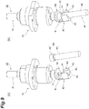
- FIG. 9(a) is a diagram for explaining a case where the sample container 40 is held by the sample-container holding member 80.
- FIG. 9(b) is a diagram of a continuation of FIG. 9(a) .
- FIG. 10 is a cross-sectional view taken along a line D-D in FIG. 9(b) . As illustrated in FIGS.
- the sample container 40 is held by the sample-container holding member 80 (that is, in container attaching step)
- the sample container 40 is positioned on the light incident side of the container attaching portion 82 (opening side of C-shape of inner surface 94) while making the longitudinal direction which is the axial direction of the cell 41 be parallel to the central axis G2 of the container attaching portion 82 (refer to FIG. 3(b) ).
- the cap 42 faces the accommodating space R of the housing portion 88, and the cell 41 faces the holding portion 89.
- the sample container 40 is pressed against the container attaching portion 82. Accordingly, the pair of arms 93 of the holding portion 89 is elastically bent outward, and the cell 41 enters the inner surface 94 while opening the C-shaped opening of the inner surface 94. As a result, the inner surface 94 has contact with the outer peripheral surface of the cell 41, and the cell 41 of the sample container 40 is held by the holding portion 89. In other words, at least three points on the outer surface of the cell 41 have contact with the holding portion 89, and the sample container 40 is held. With this operation, the cap 42 is accommodated in the accommodating space R of the housing portion 88. As illustrated in FIG.
- the holding portion 89 can surely hold the cell 41, not the cap 42, while housing the cap 42 in the housing portion 88. This makes it difficult for the cap 42 to be detached when the sample container 40 is attached/detached to/from the sample-container holding member 80, and leakage of the sample 1 in the cell 41 can be prevented. Therefore, a possibility that contamination in the integrator 20 is caused by the leakage of the sample 1 can be reduced.
- sample-container holding member 80 even a general sample container 40 including a cell 41 and a cap 42 can be easily placed in the integrator 20. Since such a sample container 40 is inexpensive, user's convenience can be enhanced Even when the general sample container 40 is used, the sample container 40 is easily used and can perform measurement with high accuracy. It is possible to provide the light measurement device 100 to a broader user.
- the sample-container holding member 80 can maintain reproducibility of placing the sample container 40 in the integrator 20. Even when the plurality of sample container 40 is attached/detached to/from the sample-container holding member 80, all the sample containers 40 can be placed at the same angle (inclination state). Therefore, measurement accuracy of the light measurement device 100 can be improved.
- the holding portion 89 holds the sample container 40 in a state where the longitudinal direction of the cell 41 is inclined to the light incident side (one side or other side in optical axis direction K) relative to the direction perpendicular to the optical axis direction K of the excitation light.
- the prism portion 84 having a prismatic shape is formed.
- the prism portion 84 has a rectangular cross section, when the support portion 81 is assembled to the fixing member 70, for example, if the rotational position of the support portion 81 is wrongly shifted from the correct rotational position by 90°, the support portion 81 cannot be assembled to the fixing member 70.
- the support portion 81 can be easily positioned in the rotational direction. Therefore, to assemble the support portion 81 to a wrong rotational position can be prevented.
- the holding portion 89 has the inner surface 94 having a C-shaped cross section, and the inner surface 94 has contact with the outer peripheral surface of the cell 41 to hold the sample container 40.
- the cell 41 of the sample container 40 can be held by being fitted into the holding portion 89. That is, the sample container 40 can be easily and detachably held.
- the sample-container holding member 80 is formed of an elastic material. That is, the holding portion 89 is formed of an elastic material. In this structure, when the sample container 40 is attached/detached to/from the sample-container holding member 80, the C-shaped opening of the holding portion 89 can be opened by using elasticity of the elastic material. The sample container 40 can be more easily held.
- the inner diameter of the C-shaped inner surface 94 of the holding portion 89 is smaller than the outer diameter of the cell 41.
- a force to close the C-shape of the holding portion 89 can be applied (apply force to cell 41 to inner side of radial direction) by using the elasticity of the elastic material. With this structure, the sample container 40 can be more reliably held.
- the groove 95 is formed in the C-shaped inner surface 94 of the holding portion 89.
- the C-shaped opening of the holding portion can be easily opened by the groove 95.
- the cell 41 can be positioned with reference to the groove 95.
- the support portion 81 and the container attaching portion 82 are separately formed.
- the container attaching portion 82 is detachably fixed to the front end portion of the support portion 81.
- the container attaching portion 82 fixed to the support portion 81 can be replaced, for example, according to the shape of the sample container 40.
- the sample containers 40 having various shapes can be easily held.
- the housing portion 88 includes the base portion 90 facing the top surface 42a of the cap 42 and the side portion 91 erected on the base portion 90.
- the base portion 90 and the side portion 91 define the accommodating space R.
- the recess 91a is formed in the side portion 91.
- the gap C is formed between the cap 42 accommodated in the accommodating space and the side portion 91.
- the elastic member 77 is provided in the rectangular hole 78 of the fixing member 70. With this structure, the support column body 83 of the support portion 81 of the sample-container holding member 80 is pressed and held by the elastic member 77. It is possible to reliably fix the sample-container holding member 80 to the fixing member 70.
- the light shielding portion 96 may be detachably fixed to the container attaching portion 82. Furthermore, for example, the light shielding portion 96 may be formed to move along the central axis G1. In this case, the light shielding portion 96 is moved to a position where the light shielding portion 96 covers the cap 42 after the sample container 40 has been attached to the container attaching portion 82.
- the structure of the housing portion 88 and the holding portion 89 is a structure in which the sample container 40 is engaged from the light incident side.
- the structure is not limited to this.
- the structure of the housing portion 88 and the holding portion 89 may be a structure in which the sample container 40 (C-shaped opening side) is engaged to the side opposite to the light incident side and may be a structure in which the sample container 40 is engaged from a direction other than that.
Landscapes
- Physics & Mathematics (AREA)
- General Physics & Mathematics (AREA)
- Spectroscopy & Molecular Physics (AREA)
- Health & Medical Sciences (AREA)
- Chemical & Material Sciences (AREA)
- Analytical Chemistry (AREA)
- Biochemistry (AREA)
- General Health & Medical Sciences (AREA)
- Life Sciences & Earth Sciences (AREA)
- Immunology (AREA)
- Pathology (AREA)
- Nuclear Medicine, Radiotherapy & Molecular Imaging (AREA)
- Investigating, Analyzing Materials By Fluorescence Or Luminescence (AREA)
- Investigating Or Analysing Materials By Optical Means (AREA)
- Sampling And Sample Adjustment (AREA)
- Optical Measuring Cells (AREA)
Abstract
Description
- One aspect of the present invention relates to a sample-container holding member, a light measurement device, and a sample-container placing method.
- Conventionally, a light measurement device has been known which irradiates a sample to be measured with excitation light and measures measurement light generated by this irradiation. For example,
Patent Literature 1 discloses a light loss measurement device which holds a sample in a state where the sample is placed in an integrator, by a clip of a sample holding means and irradiates the sample with the excitation light. - Patent Literature 1: Japanese Unexamined Patent Publication No.
H5-113386 - In the related art, since the sample is directly held by the clip, there is high possibility that the inside of the integrator is contaminated. Therefore, it is considered that the sample is contained in a sample container and is held. However, in this case, a cap of the sample container may be detached when the sample container is attached/detached to/from the clip, and there is a possibility that the sample leaks from the cell and contaminates the inside of the integrator.
- An object of one aspect of the present invention is to provide a sample-container holding member, a light measurement device, and a sample-container placing method capable of reducing a possibility that leakage of a sample contaminates inside of an integrator.
- A sample-container holding member according to one aspect of the present invention which is detachably attached to an integrator via a fixing member and holds a sample container which comprises a cell containing a sample and a cap in a state where the sample container is placed in the integrator, the sample-container holding member comprises a pillar-shaped support portion fixed to the fixing member and a container attaching portion provided at an end of the support portion in an axial direction and to which the sample container is attached, in which the container attaching portion comprises a housing portion housing the cap and a holding portion having contact with at least three points on an outer surface of the cell and holding the sample container.
- In the sample-container holding member, the holding portion can reliably hold the cell, not the cap, while housing the cap in the housing portion. This makes it difficult for the cap to be detached when the sample container is attached/detached to/from the sample-container holding member, and leakage of the sample in the cell can be prevented. Therefore, a possibility that contamination in the integrator is caused by the leakage of the sample can be reduced.
- In the sample-container holding member according to one aspect of the present invention, the holding portion may hold the sample container in a state where a longitudinal direction of the cell is inclined to one side or another side in an optical axis direction relative to a direction perpendicular to the optical direction of the excitation light to be emitted to the cell. According to this structure, all or a part of the excitation light reflected by the cell is prevented from returning to a direction of a light source of the excitation light.
- In the sample-container holding member according to one aspect of the present invention, at least a part of a contact portion of the support portion with the fixing member may have a prismatic shape. According to this structure, rotation of the sample-container holding member relative to the fixing member in a rotational direction around an axis of the support portion can be prevented.
- In the sample-container holding member according to one aspect of the present invention, the holding portion has an inner surface having a C-shaped cross section, and the inner surface may have contact with an outer surface of the cell to hold the sample container. With this structure, the cell of the sample container can be held by being fitted into the holding portion. That is, the sample container can be easily and detachably held.
- In the sample-container holding member according to one aspect of the present invention, the holding portion may be formed of an elastic material. In this structure, when the sample container is attached/detached to/from the sample-container holding member, the C-shaped opening of the holding portion can be opened by using elasticity of the elastic material. With this structure, the sample container can be more easily held.
- In the sample-container holding member according to one aspect of the present invention, an inner diameter of the C-shaped inner surface of the holding portion may be smaller than an outer diameter of the cell. In this structure, when the cell is held by the holding portion, a force to close the C-shape of the holding portion can be applied by using the elasticity of the elastic material. With this structure, the sample container can be more reliably held.
- In the sample-container holding member according to one aspect of the present invention, in the C-shaped inner surface of the holding portion, a groove extending in a direction intersecting with the C-shaped cross section may be formed. With this structure, when the sample container is attached/detached to/from the sample-container holding member, the C-shaped opening of the holding portion can be easily opened by the groove.
- In the sample-container holding member according to one aspect of the present invention, the support portion and the container attaching portion are separately formed, and the container attaching portion may be detachably fixed to an end of the support portion in the axial direction. In this structure, the container attaching portion fixed to the support portion can be replaced, for example, according to the shape of the sample container. Accordingly, the sample containers having various shapes can be easily held.
- The sample-container holding member according to one aspect of the present invention may comprise a light shielding portion provided so as to surround the cap contained in the housing portion. With this structure, absorption of the excitation light by the cap can be prevented by the light shielding portion.
- In the sample-container holding member according to one aspect of the present invention, the housing portion comprises a base portion facing a top surface of the cap and a side portion erected on the base portion, the base portion and the side portion define an accommodating space, and a gap may be formed between the cap accommodated in the accommodating space and the side portion. With this structure, a specific structure can be made so that the cap does not have contact with the sample-container holding member when the sample container is attached/detached to/from the sample-container holding member, and it can be more difficult to remove the cap.
- A light measurement device according to one aspect of the present invention is a light measurement device which measures measurement light generated by irradiating a sample with excitation light, the light measurement device comprises the sample-container holding member, an integrator in which the sample container is placed, a fixing member that detachably attaches the sample-container holding member to the integrator, a light generation unit that generates the excitation light, a light detector that detects the measurement light, and an analysis unit that analyzes detection result of the light detector.
- Since the light measurement device comprises the sample-container holding member, a possibility that contamination in the integrator is caused by the leakage of the sample can be reduced.
- A sample-container placing method according to one aspect of the present invention for placing a sample container comprising a cell containing a sample and a cap in an integrator via a fixing member by a sample-container holding member which comprises a support portion and a container attaching portion provided at an end of the support portion in an axial direction, the container attaching portion comprises a housing portion and a holding portion, the sample-container placing method comprises a support portion fixing step of fixing the support portion to the fixing member, a container attaching step of attaching the sample container to the container attaching portion, and a container placing step of placing the sample container in the integrator, in which in the container attaching step, while the cap is contained in the housing portion, the sample container is held by making the holding portion have contact with at least three points on an outer of the cell.
- In the sample-container placing method, the holding portion can reliably hold the cell, not the cap while the housing portion contains the cap. This makes it difficult for the cap to be detached when the sample container is attached/detached to/from the sample-container holding member, and leakage of the sample in the cell can be prevented. Therefore, a possibility that contamination in the integrator is caused by the leakage of the sample can be reduced.
- In the sample-container placing method according to one aspect of the present invention, in the container placing step, the sample container may be placed in a state where a longitudinal direction of the cell is inclined to one side or another side of an optical axis direction relative to a direction perpendicular to the optical axis direction of the excitation light to be emitted to the cell. In this case, all or a part of the excitation light reflected by the cell can be prevented from returning toward the excitation light source.
- In the sample-container placing method according to one aspect of the present invention, in the container attaching step, the sample container may be attached to the holding portion by being fitted into the holding portion. In this case, the sample container can be easily and detachably held.
- In the sample-container placing method according to one aspect of the present invention, before the container attaching step, the container attaching portion provided in the support portion may be replaced with another container attaching portion different from the container attaching portion. In this case, the sample containers having various shapes can be easily held.
- According to one aspect of the present invention, a sample-container holding member and a light measurement device capable of reducing a possibility that leakage of a sample contaminates inside of an integrator.
-
-
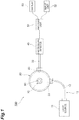
FIG. 1 is a diagram schematically illustrating a configuration of a light measurement device according to one embodiment. -
FIG. 2 is a side sectional view of a main part of the light measurement device inFIG. 1 . -
FIG. 3(a) is a front view of a fixing member and a sample-container holding member.FIG. 3(b) is a side view of the fixing member and the sample-container holding member. -
FIG. 4 is a perspective view of the divided fixing member and sample-container holding member. -
FIG. 5 is a perspective view of the divided fixing member. -
FIG. 6(a) is a side view of a support portion of the sample-container holding member.FIG. 6(b) is a cross-sectional view taken along a line A-A inFIG. 6(a) . -
FIG. 7(a) is a front view of a container attaching portion of the sample-container holding member.FIG. 7(b) is a bottom view of the container attaching portion of the sample-container holding member. -
FIG. 8(a) is a cross-sectional view taken along a line B-B inFIG. 7(a) .FIG. 8(b) is a cross-sectional view taken along a line C-C inFIG. 7(a) . -
FIG. 9(a) is a diagram for explaining a case where a sample container is held by the sample-container holding member.FIG. 9(b) is a diagram of a continuation ofFIG. 9(a) . -
FIG. 10 is a cross-sectional view taken along a line D-D inFIG. 9(b) . -
FIG. 11 is a perspective view of a sample-container holding member according to a modification. -
FIG. 12(a) is a side view of a sample-container holding member according to another modification.FIG. 12(b) is a side view of a sample-container holding member according to still another modification. -
FIG. 13 is a side sectional view of a light measurement device in a case where another sample container is directly attached to an integrator with a fixing member. - Hereinafter, an embodiment of the present invention will be described in detail with reference to the drawings. In the following description, same or corresponding components are denoted with the same reference numeral, and overlapped description will be omitted.
-
FIG. 1 is a diagram schematically illustrating a configuration of a light measurement device according to one embodiment.FIG. 2 is a side sectional view of a main part of the light measurement device inFIG. 1 . As illustrated inFIGS. 1 and2 , alight measurement device 100 according to the present embodiment measures or evaluates optical characteristics such as fluorescence characteristics of asample 1 as a sample to be measured by a photoluminescence method (PL method). Thesample 1 is, for example, a fluorescent sample such as an organic electroluminescence (EL) material or a luminescent material for a white light emitting diode (LED) or a flat panel display (FPD). As thesample 1, for example, a powder, liquid, solid, or thin film-shaped sample can be used. Here, thesample 1 is a liquid sample in which a dye or the like is mainly dissolved, and is contained in asample container 40. - The
sample container 40 includes acell 41 and a cap (lid) 42. Thecell 41 is a container in which thesample 1 is placed. Thecell 41 has a bottomed cylindrical shape. Thecell 41 is formed of glass or the like. Thecap 42 is detachably provided at an opening end of thecell 41. Thecap 42 seals the inside of thecell 41. As thecap 42, a cylindrical cap is used. An outer diameter of thecap 42 is larger than an outer diameter of thecell 41. Such asample container 40 is a general container for containing a sample. As thesample container 40, a widely distributed general-purpose product can be used. The shape and the material of thesample container 40 are not particularly limited, and various known sample containers can be used. For example, instead of thecell 41 having a cylindrical outer shape, a cell having a prismatic outer shape or the like may be used. - As the optical characteristics, an absorption rate, an internal quantum efficiency (light emission quantum yield), and an external quantum efficiency can be exemplified The absorption rate is a parameter regarding the number of photons to be absorbed. The internal quantum efficiency is a parameter regarding a rate of the number of photons of light emitted by light emission relative to the number of photons of light to be absorbed. The external quantum efficiency is a parameter regarding the number of photons to be emitted. The external quantum efficiency is a product of the absorption rate and the internal quantum efficiency. The absorption rate has a front-back relationship with a reflectance which is a parameter regarding the number of photons to be reflected. The absorption rate is synonymous with "1 - reflectance".
- The
light measurement device 100 includes an excitationlight supply unit 10, anintegrator 20, a spectroscopic detector (light detector) 45, ananalysis unit 51, aninput unit 52, and adisplay 53. The excitationlight supply unit 10 supplies excitation light with a predetermined wavelength to theintegrator 20. The excitationlight supply unit 10 includes an excitation light source (light generation unit) 11 and an incidentlight guide 12. The excitationlight supply unit 10, theintegrator 20, and thespectroscopic detector 45 are optically connected to each other. Thespectroscopic detector 45 and theanalysis unit 51 are electrically connected to each other. - The
excitation light source 11 is a light source for generating excitation light and includes, for example, a xenon lamp or a spectroscope. The wavelength of the excitation light generated by theexcitation light source 11 may vary. Theexcitation light source 11 can variably set the wavelength of the excitation light within a wavelength range of, for example, 250 nm to 1600 nm. The incidentlight guide 12 guides the excitation light generated by theexcitation light source 11 to theintegrator 20. As the incidentlight guide 12, for example, an optical fiber can be used. - The
integrator 20 is an integrating sphere and has a hollow spherical shape. Theintegrator 20 is attached to aframe 3 with, for example, a mounting screw (not shown). Aninner surface 20a of theintegrator 20 is coated with a high-diffusion reflective substance such as barium sulfate or formed of a highly reflective material having a reflectance close to one such as PTFE or Spectralon (registered trademark). Theintegrator 20 has asample introducing opening 21 for introducing thesample 1. A fixingmember 70 is inserted into and detachably attached to thesample introducing opening 21. A sample-container holding member 80 is fixed to the fixingmember 70. The sample-container holding member 80 holds thesample container 40 in a state where thesample container 40 is placed in the integrator 20 (to be described in detail later). - In the
integrator 20, anincident opening 22 to which excitation light enters and anemission opening 23 through which measurement light is emitted are provided. An incidentlight guide holder 220 for connecting the incidentlight guide 12 to theintegrator 20 is inserted into and attached to theincident opening 22. The excitation light emitted from the incidentlight guide 12 is irradiated on thesample 1 in theintegrator 20. - In the
integrator 20, the excitation light entered from the incident opening 22 is multiply diffused and reflected. In theintegrator 20, generation light generated by the irradiation on thesample 1 with the excitation light is multiply diffused and reflected. Then, the measurement light including the excitation light and the generated light is emitted from theemission opening 23. The measurement light emitted from theemission opening 23 is guided to thespectroscopic detector 45 in a subsequent stage via anemission light guide 32. The center lines of thesample introducing opening 21, the incident opening 22, and theemission opening 23 pass through the center of theintegrator 20 and are orthogonal to each other. - The
spectroscopic detector 45 detects the measurement light. Wavelength spectrum data of the detected measurement light is output to theanalysis unit 51 in the subsequent stage. As thespectroscopic detector 45, for example, a back-thinned (BT)-CCD linear image sensor, a CMOS linear image sensor, or an InGaAs linear image sensor can be used. Theanalysis unit 51 analyzes detection result of thespectroscopic detector 45. Theanalysis unit 51 is, for example, a computer. Theanalysis unit 51 includes, for example, a central processing unit (CPU) which is a processor, a random access memory (RAM) or a read only memory (ROM) which is a recording medium, and the like. Theanalysis unit 51 operates by causing hardware such as the CPU and the RAM to read a program and the like. Theanalysis unit 51 causes the CPU to perform necessary data analysis on the wavelength spectrum data generated by thespectroscopic detector 45 and to obtain information on thesample 1. Theanalysis unit 51 causes the CPU to read and write from/to the RAM. Theanalysis unit 51 may be a field-programmable gate array (FPGA), a microcomputer, a smart device, or a cloud server. Theinput unit 52 and thedisplay 53 are electrically connected to theanalysis unit 51. Theinput unit 52 is used to input an instruction regarding data analysis, input an analysis condition or a measurement condition, and the like. Theinput unit 52 is, for example, an input device such as a mouse, a keyboard, and a touch panel. Thedisplay 53 is used to display the obtained data analysis result and the like. Thedisplay 53 is a display and the like. -
FIG. 3(a) is a front view of the fixingmember 70 and the sample-container holding member 80.FIG. 3(b) is a side view of the fixingmember 70 and the sample-container holding member 80.FIG. 4 is a perspective view of the divided fixingmember 70 and sample-container holding member 80. As illustrated inFIGS. 2 to 4 , thelight measurement device 100 includes the fixingmember 70 and the sample-container holding member 80 including asupport portion 81 and acontainer attaching portion 82. -
FIG. 5 is an exploded perspective view of the fixingmember 70. As illustrated inFIGS. 2 to 5 , the fixingmember 70 detachably attaches the sample-container holding member 80 to theintegrator 20. The fixingmember 70 has a cylindrical shape having a central axis G0. The fixingmember 70 is formed to be divided into two pieces in the circumferential direction and includes a firstsemi-cylindrical portion 72A and a secondsemi-cylindrical portion 72B. It is assumed that the firstsemi-cylindrical portion 72A and the secondsemi-cylindrical portion 72B have the same shape. The firstsemi-cylindrical portion 72A and the secondsemi-cylindrical portion 72B are butted with each other in a direction orthogonal to the central axis G0. A cap member 98 (refer toFIG. 2 ) is attached to the firstsemi-cylindrical portion 72A and the secondsemi-cylindrical portion 72B which are butted with each other. As a result, the firstsemi-cylindrical portion 72A is fastened to and is integrated with the secondsemi-cylindrical portion 72B in the butting direction. - A groove 74A having a semicircular cross section and extending along the central axis G0 is formed in a
butting surface 73A of the firstsemi-cylindrical portion 72A with the secondsemi-cylindrical portion 72B. Agroove 74B having a semicircular cross section and extending along the central axis G0 is formed in abutting surface 73B of the secondsemi-cylindrical portion 72B with the firstsemi-cylindrical portion 72A. Thegrooves 74A and 74B form acylindrical hole 75 of the fixingmember 70 in a state where the firstsemi-cylindrical portion 72A and the secondsemi-cylindrical portion 72B are butted. Thecylindrical hole 75 is a circular hole passing through the fixingmember 70 along the central axis G0. An inner diameter of thecylindrical hole 75 corresponds to an outer diameter of asupport column body 83 of the support portion 81 (to be described later). - One end of the groove 74A in the axial direction has a
rectangular recess 76A having a rectangular cross section. A rectangular plate-shapedelastic member 77 formed of silicone resin and the like is bonded and fixed to a bottom surface of therectangular recess 76A. Similarly, one end of thegroove 74B in the axial direction has arectangular recess 76B having a rectangular cross section. Theelastic member 77 is bonded and fixed to a bottom surface of therectangular recess 76B. Therectangular recesses rectangular hole 78 form at one end of thecylindrical hole 75 in a state where the firstsemi-cylindrical portion 72A and the secondsemi-cylindrical portion 72B are butted with each other. Therectangular hole 78 is a rectangular-shaped space formed by enlarging one end of thecylindrical hole 75. Therectangular hole 78 has a shape corresponding to aprism portion 84 of the support portion 81 (to be described later). - On the
butting surface 73A of the firstsemi-cylindrical portion 72A, acylindrical projection 79A is provided. On thebutting surface 73B of the secondsemi-cylindrical portion 72B, acylindrical depression 79B is provided. In a state where the firstsemi-cylindrical portion 72A and the secondsemi-cylindrical portion 72B are butted with each other, theprojection 79A is fitted into thedepression 79B, and a positional misalignment of the firstsemi-cylindrical portion 72A and the secondsemi-cylindrical portion 72B is prevented. - In such a fixing
member 70, thesupport portion 81 of the sample-container holding member 80 is inserted into thecylindrical hole 75. The firstsemi-cylindrical portion 72A and the secondsemi-cylindrical portion 72B which are butted and integrated with each other hold and sandwich thesupport portion 81. With this arrangement, the fixingmember 70 fixes the sample-container holding member 80. The fixingmember 70 is inserted into thesample introducing opening 21 of theintegrator 20 so that thecontainer attaching portion 82 of the sample-container holding member 80 is placed in theintegrator 20. In this state, the fixingmember 70 is detachably fixed to abase 2a of theframe 3 with a screw and the like. - As illustrated in
FIGS. 2 to 4 , the sample-container holding member 80 is detachably attached to theintegrator 20 via the fixingmember 70. The sample-container holding member 80 holds thesample container 40 in a state where thesample container 40 is placed in theintegrator 20. Here, the sample-container holding member 80 makes the sample container 40 (sample 1) be placed at the center in theintegrator 20. The sample-container holding member 80 is formed of an elastic material. The sample-container holding member 80 is formed of a material having a reflectance equal to or more than a certain value. For example, the sample-container holding member 80 is formed of Teflon (registered trademark) or Spectralon (registered trademark). The sample-container holding member 80 includes thesupport portion 81 fixed to the fixingmember 70 and thecontainer attaching portion 82 provided at a front end portion of thesupport portion 81 in the axial direction and placed in theintegrator 20. Thesupport portion 81 and thecontainer attaching portion 82 are separately formed. -
FIG. 6(a) is a side view of thesupport portion 81 of the sample-container holding member 80.FIG. 6(b) is a cross-sectional view taken along a line A-A inFIG. 6(a) . As illustrated inFIGS. 2 to 4 andFIGS. 6(a) and 6(b) , thesupport portion 81 includes the columnarsupport column body 83 having a central axis G1. A prismatic-shapedprism portion 84 is formed between the center and the base end (left end in the drawings) of thesupport column body 83 in the axial direction. - The
prism portion 84 is a rectangular-shaped portion formed by extending thesupport column body 83 outward in the radial direction. It is assumed that theprism portion 84 has a rectangular cross section orthogonal to the axial direction. The shape of the cross section of theprism portion 84 is a rectangle and corresponds to the shape of the cross section of therectangular hole 78 of the fixingmember 70. Theprism portion 84 abuts against an inner surface of therectangular hole 78. That is, theprism portion 84 is provided in a portion of thesupport portion 81 having contact with the fixingmember 70. The base end of theprism portion 84 is tapered to be inclined relative to the axial direction. - At a position of the
support column body 83 close to the base end of theprism portion 84, a columnar firstlarge diameter portion 85 having a larger diameter than thesupport column body 83 is formed. At a front end portion of thesupport column body 83, a columnar secondlarge diameter portion 86 having a larger diameter than thesupport column body 83 is formed. A front end surface of the second large diameter portion 86 (front end portion of support portion 81) is aninclined surface 86a inclined with respect to a surface perpendicular to the axial direction. Ascrew hole 87 into which a screw N (refer toFIG. 2 ) for detachably fixing thecontainer attaching portion 82 is formed in theinclined surface 86a. - A part of the
support portion 81 between the firstlarge diameter portion 85 and the secondlarge diameter portion 86 is inserted into thecylindrical hole 75 of the fixingmember 70. In this state, theprism portion 84 is placed in (fitted into) therectangular hole 78 of the fixing member 79 without a gap and has contact with and engaged with the inner surface of therectangular hole 78. With this structure, thesupport portion 81 is fixed to the fixingmember 70 with the axial direction which is orthogonal to an optical axis direction K of the excitation light (refer toFIG. 2 ). In thesupport portion 81, theprism portion 84 has contact with therectangular hole 78 to be positioned in a rotational direction around the axis, and displacement in the rotation direction is restricted. -
FIG. 7(a) is a front view of thecontainer attaching portion 82 of the sample-container holding member 80.FIG. 7(b) is a bottom view of thecontainer attaching portion 82 of the sample-container holding member 80.FIG. 8(a) is a cross-sectional view taken along a line B-B inFIG. 7(a) .FIG. 8(b) is a cross-sectional view taken along a line C-C inFIG. 7(a) . As illustrated inFIGS. 2 to 4 andFIGS. 7(a) to 8(b) , thecontainer attaching portion 82 is a portion where thesample container 40 is detachably attached. Thecontainer attaching portion 82 has a central axis G2. Thecontainer attaching portion 82 includes ahousing portion 88 for housing thecap 42 and a holdingportion 89 for detachably holding thecell 41. Thehousing portion 88 forms a base end side of thecontainer attaching portion 82. The holdingportion 89 forms a front end side of thecontainer attaching portion 82. - The
housing portion 88 includes abase portion 90 and aside portion 91 erected on thebase portion 90. Thebase portion 90 and theside portion 91 define an accommodating space R accommodating thecap 42. Thebase portion 90 has a disc-like shape having the central axis G2 as a base axis. An outer diameter of thebase portion 90 is larger than an outer diameter of thecap 42. Onesurface 90a of thebase portion 90 faces a top surface 41a of the cap 42 (refer toFIG. 10 ). On thesurface 90a of thebase portion 90, arecess 92x having a circular cross section is formed. In the bottom surface of therecess 92x, a through-hole 92y passing through thebase portion 90 to theother surface 90b of thebase portion 90 is formed. - The
side portion 91 is provided (erected) to stand on a part of the outer peripheral portion of thesurface 90a of thebase portion 90 along the central axis G2. Specifically, when it is assumed that a side of thecontainer attaching portion 82 placed in theintegrator 20 where the excitation light enters be referred to as "light incident side", theside portion 91 is provided to be projected from a part of the side opposite to the light incident side of thesurface 90a. The outer side surface (opposite to the light incident side) of theside portion 91 is a curved surface along the shape of thebase portion 90. Arecess 91a having a rectangular cross section is formed in the inner surface (light incident side) of theside portion 91. Therecess 91a forms a gap C (refer toFIG. 10 ) between therecess 91a and thecap 42 so as not to have contact with the containedcap 42. - The holding
portion 89 is continuously provided to the front end portion of theside portion 91. The holdingportion 89 has a tubular shape of which the light incident side is notched. The holdingportion 89 includes a pair ofarms 93 which is curved so as to surround the central axis G2. Aninner surface 94 of each of the pair ofarms 93 has a C-shaped cross section orthogonal to the central axis G2. That is, the holdingportion 89 has theinner surface 94 having a C-shaped cross section orthogonal to the central axis G2. The C-shape of theinner surface 94 is opened toward the light incident side. Theinner surface 94 is a curved surface corresponding to an outer peripheral surface (outer surface) of thecell 41. Here, the inner diameter of theinner surface 94 is smaller than the outer diameter of thecell 41. - The holding
portion 89 holds thesample container 40 by having contact with at least three points on the outer peripheral surface of thecell 41. Specifically, the holdingportion 89 brings theinner surface 94 into contact with the outer peripheral surface of thecell 41 and holds thesample container 40 in a state where the central axis G2 is arranged along the longitudinal direction of thecell 41. In other words, the C-shapedinner surface 94 of the holdingportion 89 is engaged with the outer peripheral surface of thecell 41. The holdingportion 89 clamps the outer peripheral surface of thecell 41 with the pair ofarms 93.
The holdingportion 89 holds thecell 41 while bringing theinner surface 94 into contact with the outer peripheral surface of thecell 41. - On the
inner surface 94, agroove 95 extending along the central axis G2 is formed. Thegroove 95 extends in a direction perpendicular to (intersecting with) the C-shaped cross section of theinner surface 94. Thegroove 95 is a U-shaped groove having a U-shaped cross section. Thegroove 95 is provided at the center position of the C shape of theinner surface 94. Thegroove 95 extends along the central axis G2 in the central portion of theinner surface 94 as viewed from the light incident side. Thegroove 95 is arranged at a position where the pair ofarms 93 has a symmetrical structure via thegroove 95. - In such a
container attaching portion 82, thesurface 90b of thebase portion 90 has contact with theinclined surface 86a of thesupport portion 81 so that the through-hole 92y of thebase portion 90 communicates with thescrew hole 87 of thesupport portion 81. In this state, a screw is inserted into the through-hole 92y and thescrew hole 87, and thebase portion 90 is fixed to thesupport portion 81. With this structure, thecontainer attaching portion 82 is detachably fixed to the front end portion of thesupport portion 81 as the central axis G2 is inclined to the light incident side relative to the central axis G1 of thesupport portion 81. That is, the central axis G2 is inclined to the light incident side relative to the central axis G1 as separating from thesupport portion 81. The holdingportion 89 holds thesample container 40 in a state where the longitudinal direction of thecell 41 is inclined to one side or another side of the optical axis direction K relative to the direction perpendicular to the optical axis direction K of the excitation light. - In a sample-container placing method for placing the
sample container 40 in theintegrator 20 via the fixingmember 70 by the sample-container holding member 80 described above, first, thesupport portion 81 is fixed to the fixing member 70 (support portion fixing step). Thesample container 40 is attached to the container attaching portion 82 (container attaching step). The fixingmember 70 is fixed to theframe 3, and thesample container 40 is placed in the integrator 20 (container placing step). At this time, as described above, thesample container 40 is placed in theintegrator 20 in a state where the longitudinal direction of thecell 41 is inclined to the light incident side relative to the direction perpendicular to the optical axis direction K of the excitation light. -
FIG. 9(a) is a diagram for explaining a case where thesample container 40 is held by the sample-container holding member 80.FIG. 9(b) is a diagram of a continuation ofFIG. 9(a) .FIG. 10 is a cross-sectional view taken along a line D-D inFIG. 9(b) . As illustrated inFIGS. 9(a) and 9(b) , in a case where thesample container 40 is held by the sample-container holding member 80 (that is, in container attaching step), first, thesample container 40 is positioned on the light incident side of the container attaching portion 82 (opening side of C-shape of inner surface 94) while making the longitudinal direction which is the axial direction of thecell 41 be parallel to the central axis G2 of the container attaching portion 82 (refer toFIG. 3(b) ). At this time, thecap 42 faces the accommodating space R of thehousing portion 88, and thecell 41 faces the holdingportion 89. - Subsequently, the
sample container 40 is pressed against thecontainer attaching portion 82. Accordingly, the pair ofarms 93 of the holdingportion 89 is elastically bent outward, and thecell 41 enters theinner surface 94 while opening the C-shaped opening of theinner surface 94. As a result, theinner surface 94 has contact with the outer peripheral surface of thecell 41, and thecell 41 of thesample container 40 is held by the holdingportion 89. In other words, at least three points on the outer surface of thecell 41 have contact with the holdingportion 89, and thesample container 40 is held. With this operation, thecap 42 is accommodated in the accommodating space R of thehousing portion 88. As illustrated inFIG. 10 , the gap C is formed between the side surface of the containedcap 42 and theside portion 91 of thehousing portion 88. A gap C2 is formed between atop surface 42a of the containedcap 42 and thebase portion 90 of thehousing portion 88. As described above, thesample container 40 is detachably fitted into and attached to thecontainer attaching portion 82. - As described above, in the sample-
container holding member 80, the holdingportion 89 can surely hold thecell 41, not thecap 42, while housing thecap 42 in thehousing portion 88. This makes it difficult for thecap 42 to be detached when thesample container 40 is attached/detached to/from the sample-container holding member 80, and leakage of thesample 1 in thecell 41 can be prevented. Therefore, a possibility that contamination in theintegrator 20 is caused by the leakage of thesample 1 can be reduced. - In addition, according to the sample-
container holding member 80, even ageneral sample container 40 including acell 41 and acap 42 can be easily placed in theintegrator 20. Since such asample container 40 is inexpensive, user's convenience can be enhanced Even when thegeneral sample container 40 is used, thesample container 40 is easily used and can perform measurement with high accuracy. It is possible to provide thelight measurement device 100 to a broader user. - Furthermore, by holding the
sample container 40 by having contact with at least three points on the outer surface of thecell 41, the sample-container holding member 80 can maintain reproducibility of placing thesample container 40 in theintegrator 20. Even when the plurality ofsample container 40 is attached/detached to/from the sample-container holding member 80, all thesample containers 40 can be placed at the same angle (inclination state). Therefore, measurement accuracy of thelight measurement device 100 can be improved. - In the sample-
container holding member 80, the holdingportion 89 holds thesample container 40 in a state where the longitudinal direction of thecell 41 is inclined to the light incident side (one side or other side in optical axis direction K) relative to the direction perpendicular to the optical axis direction K of the excitation light. With this structure, the following effects are obtained. That is, all or a part of the excitation light reflected by thecell 41 can be prevented from returning toward the excitation light source 11 (incident opening 22). In a case where thecell 41 is inclined to a direction other than the optical axis direction K and is held, there is a possibility that thecell 41 is not irradiated with the excitation light. Therefore, thecell 41 can be reliably irradiated with the excitation light. - In the sample-
container holding member 80, at least a part of a contact portion of thesupport portion 81 with the fixingmember 70, theprism portion 84 having a prismatic shape is formed. With this structure, rotation of the sample-container holding member 80 relative to the fixingmember 70 in the rotational direction around the central axis G1 can be prevented. The angle of thesample container 40 in the rotational direction does not change. - Particularly, since the
prism portion 84 has a rectangular cross section, when thesupport portion 81 is assembled to the fixingmember 70, for example, if the rotational position of thesupport portion 81 is wrongly shifted from the correct rotational position by 90°, thesupport portion 81 cannot be assembled to the fixingmember 70. Thesupport portion 81 can be easily positioned in the rotational direction. Therefore, to assemble thesupport portion 81 to a wrong rotational position can be prevented. - In the sample-
container holding member 80, the holdingportion 89 has theinner surface 94 having a C-shaped cross section, and theinner surface 94 has contact with the outer peripheral surface of thecell 41 to hold thesample container 40. With this structure, thecell 41 of thesample container 40 can be held by being fitted into the holdingportion 89. That is, thesample container 40 can be easily and detachably held. - The sample-
container holding member 80 is formed of an elastic material. That is, the holdingportion 89 is formed of an elastic material. In this structure, when thesample container 40 is attached/detached to/from the sample-container holding member 80, the C-shaped opening of the holdingportion 89 can be opened by using elasticity of the elastic material. Thesample container 40 can be more easily held. - In the sample-
container holding member 80, the inner diameter of the C-shapedinner surface 94 of the holdingportion 89 is smaller than the outer diameter of thecell 41. In this structure, when thecell 41 is held by the holdingportion 89, a force to close the C-shape of the holdingportion 89 can be applied (apply force tocell 41 to inner side of radial direction) by using the elasticity of the elastic material. With this structure, thesample container 40 can be more reliably held. - In the sample-
container holding member 80, thegroove 95 is formed in the C-shapedinner surface 94 of the holdingportion 89. When thesample container 40 is attached/detached to/from the sample-container holding member 80, the C-shaped opening of the holding portion can be easily opened by thegroove 95. Furthermore, thecell 41 can be positioned with reference to thegroove 95. - In the sample-
container holding member 80, thesupport portion 81 and thecontainer attaching portion 82 are separately formed. Thecontainer attaching portion 82 is detachably fixed to the front end portion of thesupport portion 81. In this structure, thecontainer attaching portion 82 fixed to thesupport portion 81 can be replaced, for example, according to the shape of thesample container 40. Thesample containers 40 having various shapes can be easily held. - In the sample-
container holding member 80, thehousing portion 88 includes thebase portion 90 facing thetop surface 42a of thecap 42 and theside portion 91 erected on thebase portion 90. Thebase portion 90 and theside portion 91 define the accommodating space R. Therecess 91a is formed in theside portion 91. The gap C is formed between thecap 42 accommodated in the accommodating space and theside portion 91. With this structure, when thesample container 40 is attached/detached to/from the sample-container holding member 80, a specific structure can be made so that thecap 42 does not have contact with the sample-container holding member 80, and it can be more difficult to remove thecap 42. Misalignment of thecell 41 held by the holdingportion 89 caused by interference between thecap 42 and thehousing portion 88 can be prevented. - Since the
light measurement device 100 includes the sample-container holding member 80, the action effect obtained by the sample-container holding member 80, that is, the effect of reducing the possibility of contamination in theintegrator 20 caused by the leakage of thesample 1 can be obtained. - In the sample-container placing method, the holding
portion 89 can reliably hold thecell 41, not thecap 42 while thehousing portion 88 contains thecap 42. This makes it difficult for thecap 42 to be detached when thesample container 40 is attached/detached to/from the sample-container holding member 80, and leakage of thesample 1 in thecell 41 can be prevented. Therefore, it is possible to reduce possibility that the leakage of thesample 1 contaminates the inside of theintegrator 20. - In the sample-container placing method, the
sample container 40 is placed in a state where the longitudinal direction of thecell 41 is inclined to the light incident side (one side or the other side in optical axis direction K) relative to the direction perpendicular to the optical axis direction K of the excitation light to be emitted to thecell 41. With this placement, all or a part of the excitation light reflected by thecell 41 can be prevented from returning toward theexcitation light source 11. In a case where thecell 41 is placed as being inclined to the direction other than the optical axis direction K, there is a possibility that thecell 41 is not irradiated with the excitation light. Therefore, with this sample-container placing method, thecell 41 can be reliably irradiated with the excitation light. - In the sample-container placing method, the
sample container 40 is attached to the holdingportion 89 by being fitted into the holdingportion 89. Accordingly, thesample container 40 can be easily and detachably held. - The
elastic member 77 is provided in therectangular hole 78 of the fixingmember 70. With this structure, thesupport column body 83 of thesupport portion 81 of the sample-container holding member 80 is pressed and held by theelastic member 77. It is possible to reliably fix the sample-container holding member 80 to the fixingmember 70. -
FIG. 11 is a perspective view of a sample-container holding member 80A according to a modification. As illustrated inFIG. 11 , the sample-container holding member 80A includes a tubularlight shielding portion 96. Thelight shielding portion 96 is placed outside thehousing portion 88. Thelight shielding portion 96 is provided so as to surround thecap 42 contained in thehousing portion 88. Thelight shielding portion 96 shields thecap 42 from the excitation light to be irradiated. Thelight shielding portion 96 is formed of a material having light shielding property relative to the excitation light. For example, thelight shielding portion 96 is formed of a material different from the cell 41 (for example, resin). Furthermore, for example, thelight shielding portion 96 may be coated with a high-diffusion reflective substance such as barium sulfate which is the same material as the inner surface of theintegrator 20. - In the sample-
container holding member 80A, thecap 42 of thesample container 40 held by the holdingportion 89 is covered with thelight shielding portion 96 so that absorption of the excitation light by thecap 42 can be prevented. Measurement errors of the spectroscopic detector 45 (refer toFIG. 1 ) can be reduced. The influence of the absorption of the excitation light by thecap 42 on the measurement accuracy can be reduced. - Note that, for example, the
light shielding portion 96 may be detachably fixed to thecontainer attaching portion 82. Furthermore, for example, thelight shielding portion 96 may be formed to move along the central axis G1. In this case, thelight shielding portion 96 is moved to a position where thelight shielding portion 96 covers thecap 42 after thesample container 40 has been attached to thecontainer attaching portion 82. -
FIG. 12(a) is a side view of a sample-container holding member 80B according to a modification.FIG. 12(b) is a side view of a sample-container holding member 80C according to a modification. As described above, since thecontainer attaching portion 82 is detachably fixed to the end of thesupport portion 81, thecontainer attaching portion 82 can be replaced with various container attaching portions. For example, the sample-container holding member includes a plurality of kinds ofcontainer attaching portions 82 including the holdingportions 89 having various shapes, and any one of thecontainer attaching portions 82 according to thesample container 40 may be attached to thesupport portion 81. - As illustrated in
FIG. 12(a) , in a case where another sample container which is larger than thesample container 40 is held, the sample-container holding member 80B may be employed. In the sample-container holding member 80B, acontainer attaching portion 82B of which dimensions are larger than those of thecontainer attaching portion 82 is fixed to the end of thesupport portion 81. As illustrated inFIG. 12(b) , in a case where another sample container which is smaller than thesample container 40 is held, the sample-container holding member 80C may be employed. In the sample-container holding member 80C, acontainer attaching portion 82C of which dimensions are smaller than those of thecontainer attaching portion 82 is fixed to the end of thesupport portion 81. In a case where a sample container having a prismatic cell is held, a container attaching portion of which an inner surface of a holding portion corresponds to the outer surface of the cell may be fixed to the end of thesupport portion 81. - That is, the light measurement device and the sample-container holding member include a plurality of container attaching portions including a plurality of holding portions having different shapes from each other, and the container attaching portion fixed to the end of the
support portion 81 may be replaced with any one of the plurality of container attaching portions. Before thesample container 40 is attached to the container attaching portion 82 (before container attaching step), thecontainer attaching portion 82 provided in thesupport portion 81 may be replaced with another container attaching portion different from thecontainer attaching portion 82. Accordingly, thesample containers 40 having various shapes can be easily held. -
FIG. 13 is a side sectional view of thelight measurement device 100 in a case where anothersample container 97 is directly attached to theintegrator 20 with the fixingmember 70. As illustrated inFIG. 13 , in thelight measurement device 100, it is not necessary to use the sample-container holding member 80 (refer toFIG. 2 ) by employing thesample container 97. That is, the fixingmember 70 can directly attach thesample container 97 to theintegrator 20 without having the sample-container holding member 80 (refer toFIG. 2 ) therebetween. - The
sample container 97 is a unique optical cell corresponding to the fixingmember 70. Thesample container 97 is formed of quartz or synthetic quartz. Thesample container 97 includes a square pillar-shaped hollow cellmain body 97a in which thesample 1 is stored and a rod-like branch pipe 97b extending in a tubular shape from the cellmain body 97a. Thebranch pipe 97b of thesample container 97 is inserted into and fixed to thecylindrical hole 75 of the fixingmember 70. Thebranch pipe 97b is sandwiched and held between the firstsemi-cylindrical portion 72A and the secondsemi-cylindrical portion 72B as being pressed by theelastic member 77. Accordingly, the fixingmember 70 holds thesample container 97 in a state where the cellmain body 97a containing thesample 1 is placed in theintegrator 20. - That is, the light measurement device may further include the
sample container 97. In this case, by using thesample container 97, the light measurement device can perform measurement with high accuracy and can use ultraviolet light as excitation light. Accordingly, it is possible to appropriately select the use of the sample-container holding member 80 and the use of thesample container 97, and measurement according to accuracy or conditions can be performed. - The embodiment of the present invention has been described above. However, the present invention is not limited to the embodiment described above.
- In the embodiment, the structure of the
housing portion 88 and the holdingportion 89 is a structure in which thesample container 40 is engaged from the light incident side. However, the structure is not limited to this. For example, the structure of thehousing portion 88 and the holdingportion 89 may be a structure in which the sample container 40 (C-shaped opening side) is engaged to the side opposite to the light incident side and may be a structure in which thesample container 40 is engaged from a direction other than that. - In the embodiment, the
cell 41 of thesample container 40 is formed of glass. However, thecell 41 may be formed of quartz. In the embodiment, the holdingportion 89 holds thesample container 40 in a state where the longitudinal direction of thecell 41 is inclined to the light incident side relative to the central axis G1. However, the holdingportion 89 may hold thesample container 40 in a state where the longitudinal direction of thecell 41 is inclined to the other side of the light incident side relative to the central axis G1. - In the embodiment, the integrating sphere is used as the
integrator 20. However, it is preferable that a means for spatially integrating the light inside the integrator 20 (optical component) be used. For example, an integrating hemisphere disclosed inJP 2009-103654 A portion 89 according to the embodiment has a structure in which theinner surface 94 has contact with the outer peripheral surface of thecell 41. However, the holdingportion 89 is not limited to this, and the structure may be used in which the holdingportion 89 has contact with at least three points on the outer surface of the cell 41 (it is preferable that the holdingportion 89 is capable of having contact with at least three points of outer surface of cell 41). The support portion fixing step, the container attaching step, and the container placing step are performed in no particular order, and may be performed in any order. -
- 1
- sample
- 11
- excitation light source (light generation unit)
- 20
- integrator
- 40
- sample container
- 41
- cell
- 42
- cap
- 42a
- top surface
- 45
- spectroscopic detector (light detector)
- 51
- analysis unit
- 70
- fixing member
- 80, 80A, 80B, 80C
- sample-container holding member
- 81
- support portion
- 82
- container attaching portion
- 88
- housing portion
- 89
- holding portion
- 90
- base portion
- 91
- side portion
- 94
- inner surface
- 95
- groove
- 96
- light shielding portion
- 100
- light measurement device
- C
- gap
- K
- optical axis direction
- R
- accommodating space
Claims (15)
- A sample-container holding member detachably attached to an integrator via a fixing member and holding a sample container comprising a cell containing a sample and a cap in a state where the sample container is placed in the integrator, the sample-container holding member comprising:a pillar-shaped support portion fixed to the fixing member; anda container attaching portion provided at an end of the support portion in an axial direction and to which the sample container is attached, whereinthe container attaching portion comprises:a housing portion housing the cap; anda holding portion having contact with at least three points on an outer surface of the cell and holding the sample container.
- The sample-container holding member according to claim 1, wherein
the holding portion holds the sample container in a state where a longitudinal direction of the cell is inclined to one side or another side in an optical axis direction relative to a direction perpendicular to the optical axis direction of excitation light to be emitted to the cell. - The sample-container holding member according to claim 1 or 2, wherein
at least a part of a contact portion of the support portion with the fixing member has a prismatic shape. - The sample-container holding member according to any one of claims 1 to 3, wherein
the holding portion has an inner surface having a C-shaped cross section, and the inner surface has contact with an outer surface of the cell so that the holding portion holds the sample container. - The sample-container holding member according to claim 4, wherein
the holding portion is formed of an elastic material. - The sample-container holding member according to claim 5, wherein
an inner diameter of the C-shaped inner surface of the holding portion is smaller than an outer diameter of the cell. - The sample-container holding member according to any one of claims 4 to 6, wherein
in the C-shaped inner surface of the holding portion, a groove extending in a direction intersecting with the C-shaped cross section is formed. - The sample-container holding member according to any one of claims 1 to 7, wherein
the support portion and the container attaching portion are separately formed, and
the container attaching portion is detachably fixed to the end of the support portion in the axial direction. - The sample-container holding member according to any one of claims 1 to 8, further comprising:
a light shielding portion provided so as to surround the cap contained in the housing portion. - The sample-container holding member according to any one of claims 1 to 9, wherein
the housing portion comprises a base portion facing a top surface of the cap and a side portion provided to be erected on the base portion,
the base portion and the side portion define an accommodating space accommodating the cap, and
a gap is formed between the cap contained in the accommodating space and the side portion. - A light measurement device measuring measurement light generated by irradiating a sample with excitation light, the light measurement device comprising:the sample-container holding member according to any one of claims 1 to 10;an integrator in which the sample container is placed;a fixing member configured to detachably attach the sample-container holding member to the integrator;a light generation unit configured to generate the excitation light;a light detector configured to detect the measurement light; andan analysis unit configured to analyze detection result of the light detector.
- A sample-container placing method for placing a sample container comprising a cell containing a sample and a cap in an integrator via a fixing member by a sample-container holding member which comprises a support portion and a container attaching portion provided at an end of the support portion in an axial direction, the container attaching portion comprises a housing portion and a holding portion, the sample-container placing method comprising:a support portion fixing step of fixing the support portion to the fixing member;a container attaching step of attaching the sample container to the container attaching portion; anda container placing step of placing the sample container in the integrator, whereinin the container attaching step, while the cap is contained in the housing portion, the sample container is held by making the holding portion have contact with at least three points on an outer of the cell.
- The sample-container placing method according to claim 12, wherein
in the container placing step, the sample container is placed in a state where a longitudinal direction of the cell is inclined to one side or another side in an optical axis direction relative to a direction perpendicular to the optical axis direction of excitation light to be emitted to the cell. - The sample-container placing method according to claim 12 or 13, wherein
in the container attaching step, the sample container is attached to the holding portion by being fitted into the holding portion. - The sample-container placing method according to any one of claims 12 to 14, wherein
before the container attaching step, the container attaching portion provided in the support portion is replaced with another container attaching portion different from the container attaching portion.
Applications Claiming Priority (2)
| Application Number | Priority Date | Filing Date | Title |
|---|---|---|---|
| JP2016147251A JP6227068B1 (en) | 2016-07-27 | 2016-07-27 | Sample container holding member, optical measurement device, and sample container arrangement method |
| PCT/JP2017/017550 WO2018020773A1 (en) | 2016-07-27 | 2017-05-09 | Sample-container holding member, light measurement device, and sample-container placing method |
Publications (3)
| Publication Number | Publication Date |
|---|---|
| EP3492903A1 true EP3492903A1 (en) | 2019-06-05 |
| EP3492903A4 EP3492903A4 (en) | 2020-03-11 |
| EP3492903B1 EP3492903B1 (en) | 2024-09-25 |
Family
ID=60265897
Family Applications (1)
| Application Number | Title | Priority Date | Filing Date |
|---|---|---|---|
| EP17833784.6A Active EP3492903B1 (en) | 2016-07-27 | 2017-05-09 | Light measurement device with sample-container holding member, and sample-container placing method |
Country Status (7)
| Country | Link |
|---|---|
| US (1) | US11150178B2 (en) |
| EP (1) | EP3492903B1 (en) |
| JP (1) | JP6227068B1 (en) |
| KR (1) | KR102259936B1 (en) |
| CN (1) | CN109477787B (en) |
| TW (1) | TWI729170B (en) |
| WO (1) | WO2018020773A1 (en) |
Families Citing this family (2)
| Publication number | Priority date | Publication date | Assignee | Title |
|---|---|---|---|---|
| US11975331B2 (en) | 2018-03-14 | 2024-05-07 | Grainsense Oy | Sample containers for use inside integrating cavities, and tools |
| JP7626616B2 (en) * | 2020-12-25 | 2025-02-04 | 株式会社日立ハイテクサイエンス | Spectrofluorophotometer, spectrofluorometric measurement method, and image capturing method |
Family Cites Families (23)
| Publication number | Priority date | Publication date | Assignee | Title |
|---|---|---|---|---|
| CA922028A (en) * | 1969-06-06 | 1973-02-27 | Combustion Engineering | Irradiation surveillance capsule assemblies for nuclear reactors |
| US4645340A (en) * | 1983-06-01 | 1987-02-24 | Boston University | Optically reflective sphere for efficient collection of Raman scattered light |
| JPH05113386A (en) * | 1990-11-30 | 1993-05-07 | Shimadzu Corp | Light loss measuring device |
| US20020063864A1 (en) * | 2000-09-29 | 2002-05-30 | Honig Jordan S. | Athermal mounting system |
| JP2005083885A (en) * | 2003-09-08 | 2005-03-31 | Kyoto Univ | Sample container and fluid sample analysis method |
| WO2006090681A1 (en) * | 2005-02-25 | 2006-08-31 | Matsushita Electric Industrial Co., Ltd. | Two dimensional image forming device |
| CN100583407C (en) * | 2005-04-27 | 2010-01-20 | 奥林巴斯株式会社 | Appearance inspection device, appearance inspection method, and edge inspection unit mountable on appearance inspection device |
| CN102033055B (en) | 2007-03-01 | 2013-05-29 | 浜松光子学株式会社 | Light detection device |
| JP4961291B2 (en) * | 2007-07-24 | 2012-06-27 | 浜松ホトニクス株式会社 | Sample holder jig |
| JP4452737B2 (en) | 2007-10-25 | 2010-04-21 | 大塚電子株式会社 | Luminometer and measuring method |
| JP5161755B2 (en) * | 2008-12-25 | 2013-03-13 | 浜松ホトニクス株式会社 | Spectrometer, spectroscopic method, and spectroscopic program |
| JP5640257B2 (en) * | 2010-03-18 | 2014-12-17 | 大塚電子株式会社 | Quantum efficiency measurement method and quantum efficiency measurement device |
| JP5491368B2 (en) * | 2010-11-29 | 2014-05-14 | 浜松ホトニクス株式会社 | Quantum yield measuring apparatus and quantum yield measuring method |
| JP5491369B2 (en) | 2010-11-29 | 2014-05-14 | 浜松ホトニクス株式会社 | Quantum yield measuring device |
| JP2012132861A (en) * | 2010-12-24 | 2012-07-12 | Horiba Ltd | Optical measuring device |
| US20130302212A1 (en) * | 2011-01-21 | 2013-11-14 | Hitachi High-Technologies Corporation | Automatic analyzer |
| JP5603376B2 (en) | 2012-07-02 | 2014-10-08 | 浜松ホトニクス株式会社 | Sample holder |
| JP5529305B1 (en) | 2013-02-04 | 2014-06-25 | 浜松ホトニクス株式会社 | Spectrometer and spectroscopic method |
| KR20160075764A (en) * | 2013-10-29 | 2016-06-29 | 오하이오 유니버시티 | Treating non-point source pollutants in water runoff |
| JP6279399B2 (en) * | 2014-05-23 | 2018-02-14 | 浜松ホトニクス株式会社 | Optical measuring device and optical measuring method |
| JP6629504B2 (en) * | 2014-09-02 | 2020-01-15 | 株式会社堀場製作所 | Optical analyzer |
| US10118176B2 (en) * | 2014-10-17 | 2018-11-06 | Omni International, Inc. | Sample-tube holder for easy tube insertion and removal |
| CN205139316U (en) | 2015-11-04 | 2016-04-06 | 中国计量学院 | Integrated encapsulation emitting diode's of chip photochromic detecting system on board |
-
2016
- 2016-07-27 JP JP2016147251A patent/JP6227068B1/en active Active
-
2017
- 2017-05-09 WO PCT/JP2017/017550 patent/WO2018020773A1/en not_active Ceased
- 2017-05-09 EP EP17833784.6A patent/EP3492903B1/en active Active
- 2017-05-09 CN CN201780046060.9A patent/CN109477787B/en active Active
- 2017-05-09 US US16/316,125 patent/US11150178B2/en active Active
- 2017-05-09 KR KR1020187033921A patent/KR102259936B1/en active Active
- 2017-07-17 TW TW106123847A patent/TWI729170B/en active
Also Published As
| Publication number | Publication date |
|---|---|
| JP2018017580A (en) | 2018-02-01 |
| TW201812256A (en) | 2018-04-01 |
| EP3492903A4 (en) | 2020-03-11 |
| KR102259936B1 (en) | 2021-06-01 |
| CN109477787B (en) | 2022-05-10 |
| EP3492903B1 (en) | 2024-09-25 |
| TWI729170B (en) | 2021-06-01 |
| JP6227068B1 (en) | 2017-11-08 |
| CN109477787A (en) | 2019-03-15 |
| KR20190034144A (en) | 2019-04-01 |
| US11150178B2 (en) | 2021-10-19 |
| US20210131948A1 (en) | 2021-05-06 |
| WO2018020773A1 (en) | 2018-02-01 |
Similar Documents
| Publication | Publication Date | Title |
|---|---|---|
| KR101359148B1 (en) | Photodetector and jig for sample holder | |
| KR101790825B1 (en) | Quantum-yield measurement device | |
| TWI613434B (en) | Spectrometry device and spectrometry method | |
| EP3492903B1 (en) | Light measurement device with sample-container holding member, and sample-container placing method | |
| JP5479496B2 (en) | Main module for optical measuring instruments | |
| CN106990059B (en) | Liquid sample measuring device and measuring method | |
| EP4189341B1 (en) | Absorbance spectroscopy analyzer and method of use | |
| KR102359887B1 (en) | optical instrumentation | |
| US20240337586A1 (en) | Capillary array window holder and related systems and methods | |
| CN114563515A (en) | Structure of flow cell assembly for chromatographic detector and method for manufacturing capillary tube | |
| KR20110102870A (en) | Spectrometer | |
| WO2020217356A1 (en) | Chromatography detector flow cell and chromatography detector | |
| Joó et al. | The THESEUS Space Mission and the Infrared Telescope Calibration Unit | |
| JP2026514825A (en) | Identification of substances stored in containers using a portable Raman probe. | |
| KR20040059399A (en) | Spectrometer for uv and pl | |
| JP2012021860A (en) | Spectrophotometer |
Legal Events
| Date | Code | Title | Description |
|---|---|---|---|
| STAA | Information on the status of an ep patent application or granted ep patent |
Free format text: STATUS: THE INTERNATIONAL PUBLICATION HAS BEEN MADE |
|
| PUAI | Public reference made under article 153(3) epc to a published international application that has entered the european phase |
Free format text: ORIGINAL CODE: 0009012 |
|
| STAA | Information on the status of an ep patent application or granted ep patent |
Free format text: STATUS: REQUEST FOR EXAMINATION WAS MADE |
|
| 17P | Request for examination filed |
Effective date: 20181029 |
|
| AK | Designated contracting states |
Kind code of ref document: A1 Designated state(s): AL AT BE BG CH CY CZ DE DK EE ES FI FR GB GR HR HU IE IS IT LI LT LU LV MC MK MT NL NO PL PT RO RS SE SI SK SM TR |
|
| AX | Request for extension of the european patent |
Extension state: BA ME |
|
| DAV | Request for validation of the european patent (deleted) | ||
| DAX | Request for extension of the european patent (deleted) | ||
| A4 | Supplementary search report drawn up and despatched |
Effective date: 20200211 |
|
| RIC1 | Information provided on ipc code assigned before grant |
Ipc: G01N 1/28 20060101ALI20200205BHEP Ipc: G01N 21/64 20060101ALI20200205BHEP Ipc: G01N 21/01 20060101AFI20200205BHEP Ipc: G01J 3/02 20060101ALI20200205BHEP Ipc: G01N 21/15 20060101ALI20200205BHEP |
|
| STAA | Information on the status of an ep patent application or granted ep patent |
Free format text: STATUS: EXAMINATION IS IN PROGRESS |
|
| 17Q | First examination report despatched |
Effective date: 20220719 |
|
| GRAP | Despatch of communication of intention to grant a patent |
Free format text: ORIGINAL CODE: EPIDOSNIGR1 |
|
| STAA | Information on the status of an ep patent application or granted ep patent |
Free format text: STATUS: GRANT OF PATENT IS INTENDED |
|
| RIC1 | Information provided on ipc code assigned before grant |
Ipc: G01N 1/28 20060101ALN20240613BHEP Ipc: G01N 21/15 20060101ALI20240613BHEP Ipc: G01J 3/02 20060101ALI20240613BHEP Ipc: G01N 21/64 20060101ALI20240613BHEP Ipc: G01N 21/01 20060101AFI20240613BHEP |
|
| INTG | Intention to grant announced |
Effective date: 20240627 |
|
| RIC1 | Information provided on ipc code assigned before grant |
Ipc: G01N 1/28 20060101ALN20240613BHEP Ipc: G01N 21/15 20060101ALI20240613BHEP Ipc: G01J 3/02 20060101ALI20240613BHEP Ipc: G01N 21/64 20060101ALI20240613BHEP Ipc: G01N 21/01 20060101AFI20240613BHEP |
|
| GRAS | Grant fee paid |
Free format text: ORIGINAL CODE: EPIDOSNIGR3 |
|
| GRAA | (expected) grant |
Free format text: ORIGINAL CODE: 0009210 |
|
| STAA | Information on the status of an ep patent application or granted ep patent |
Free format text: STATUS: THE PATENT HAS BEEN GRANTED |
|
| AK | Designated contracting states |
Kind code of ref document: B1 Designated state(s): AL AT BE BG CH CY CZ DE DK EE ES FI FR GB GR HR HU IE IS IT LI LT LU LV MC MK MT NL NO PL PT RO RS SE SI SK SM TR |
|
| REG | Reference to a national code |
Ref country code: GB Ref legal event code: FG4D |
|
| REG | Reference to a national code |
Ref country code: CH Ref legal event code: EP |
|
| REG | Reference to a national code |
Ref country code: DE Ref legal event code: R096 Ref document number: 602017085109 Country of ref document: DE |
|
| P01 | Opt-out of the competence of the unified patent court (upc) registered |
Free format text: CASE NUMBER: APP_52213/2024 Effective date: 20240917 |
|
| REG | Reference to a national code |
Ref country code: IE Ref legal event code: FG4D Ref country code: NL Ref legal event code: FP |
|
| REG | Reference to a national code |
Ref country code: LT Ref legal event code: MG9D |
|
| PG25 | Lapsed in a contracting state [announced via postgrant information from national office to epo] |
Ref country code: NO Free format text: LAPSE BECAUSE OF FAILURE TO SUBMIT A TRANSLATION OF THE DESCRIPTION OR TO PAY THE FEE WITHIN THE PRESCRIBED TIME-LIMIT Effective date: 20241225 |
|
| PG25 | Lapsed in a contracting state [announced via postgrant information from national office to epo] |
Ref country code: GR Free format text: LAPSE BECAUSE OF FAILURE TO SUBMIT A TRANSLATION OF THE DESCRIPTION OR TO PAY THE FEE WITHIN THE PRESCRIBED TIME-LIMIT Effective date: 20241226 Ref country code: FI Free format text: LAPSE BECAUSE OF FAILURE TO SUBMIT A TRANSLATION OF THE DESCRIPTION OR TO PAY THE FEE WITHIN THE PRESCRIBED TIME-LIMIT Effective date: 20240925 |
|
| PG25 | Lapsed in a contracting state [announced via postgrant information from national office to epo] |
Ref country code: BG Free format text: LAPSE BECAUSE OF FAILURE TO SUBMIT A TRANSLATION OF THE DESCRIPTION OR TO PAY THE FEE WITHIN THE PRESCRIBED TIME-LIMIT Effective date: 20240925 |
|
| PG25 | Lapsed in a contracting state [announced via postgrant information from national office to epo] |
Ref country code: LV Free format text: LAPSE BECAUSE OF FAILURE TO SUBMIT A TRANSLATION OF THE DESCRIPTION OR TO PAY THE FEE WITHIN THE PRESCRIBED TIME-LIMIT Effective date: 20240925 |
|
| PG25 | Lapsed in a contracting state [announced via postgrant information from national office to epo] |
Ref country code: RS Free format text: LAPSE BECAUSE OF FAILURE TO SUBMIT A TRANSLATION OF THE DESCRIPTION OR TO PAY THE FEE WITHIN THE PRESCRIBED TIME-LIMIT Effective date: 20241225 |
|
| PG25 | Lapsed in a contracting state [announced via postgrant information from national office to epo] |
Ref country code: RS Free format text: LAPSE BECAUSE OF FAILURE TO SUBMIT A TRANSLATION OF THE DESCRIPTION OR TO PAY THE FEE WITHIN THE PRESCRIBED TIME-LIMIT Effective date: 20241225 Ref country code: NO Free format text: LAPSE BECAUSE OF FAILURE TO SUBMIT A TRANSLATION OF THE DESCRIPTION OR TO PAY THE FEE WITHIN THE PRESCRIBED TIME-LIMIT Effective date: 20241225 Ref country code: LV Free format text: LAPSE BECAUSE OF FAILURE TO SUBMIT A TRANSLATION OF THE DESCRIPTION OR TO PAY THE FEE WITHIN THE PRESCRIBED TIME-LIMIT Effective date: 20240925 Ref country code: GR Free format text: LAPSE BECAUSE OF FAILURE TO SUBMIT A TRANSLATION OF THE DESCRIPTION OR TO PAY THE FEE WITHIN THE PRESCRIBED TIME-LIMIT Effective date: 20241226 Ref country code: FI Free format text: LAPSE BECAUSE OF FAILURE TO SUBMIT A TRANSLATION OF THE DESCRIPTION OR TO PAY THE FEE WITHIN THE PRESCRIBED TIME-LIMIT Effective date: 20240925 Ref country code: BG Free format text: LAPSE BECAUSE OF FAILURE TO SUBMIT A TRANSLATION OF THE DESCRIPTION OR TO PAY THE FEE WITHIN THE PRESCRIBED TIME-LIMIT Effective date: 20240925 |
|
| REG | Reference to a national code |
Ref country code: AT Ref legal event code: MK05 Ref document number: 1727010 Country of ref document: AT Kind code of ref document: T Effective date: 20240925 |
|
| PG25 | Lapsed in a contracting state [announced via postgrant information from national office to epo] |
Ref country code: IS Free format text: LAPSE BECAUSE OF FAILURE TO SUBMIT A TRANSLATION OF THE DESCRIPTION OR TO PAY THE FEE WITHIN THE PRESCRIBED TIME-LIMIT Effective date: 20250125 Ref country code: PT Free format text: LAPSE BECAUSE OF FAILURE TO SUBMIT A TRANSLATION OF THE DESCRIPTION OR TO PAY THE FEE WITHIN THE PRESCRIBED TIME-LIMIT Effective date: 20250127 |
|
| PG25 | Lapsed in a contracting state [announced via postgrant information from national office to epo] |
Ref country code: RO Free format text: LAPSE BECAUSE OF FAILURE TO SUBMIT A TRANSLATION OF THE DESCRIPTION OR TO PAY THE FEE WITHIN THE PRESCRIBED TIME-LIMIT Effective date: 20240925 Ref country code: SM Free format text: LAPSE BECAUSE OF FAILURE TO SUBMIT A TRANSLATION OF THE DESCRIPTION OR TO PAY THE FEE WITHIN THE PRESCRIBED TIME-LIMIT Effective date: 20240925 |
|
| PG25 | Lapsed in a contracting state [announced via postgrant information from national office to epo] |
Ref country code: ES Free format text: LAPSE BECAUSE OF FAILURE TO SUBMIT A TRANSLATION OF THE DESCRIPTION OR TO PAY THE FEE WITHIN THE PRESCRIBED TIME-LIMIT Effective date: 20240925 |
|
| PG25 | Lapsed in a contracting state [announced via postgrant information from national office to epo] |
Ref country code: AT Free format text: LAPSE BECAUSE OF FAILURE TO SUBMIT A TRANSLATION OF THE DESCRIPTION OR TO PAY THE FEE WITHIN THE PRESCRIBED TIME-LIMIT Effective date: 20240925 Ref country code: EE Free format text: LAPSE BECAUSE OF FAILURE TO SUBMIT A TRANSLATION OF THE DESCRIPTION OR TO PAY THE FEE WITHIN THE PRESCRIBED TIME-LIMIT Effective date: 20240925 |
|
| PG25 | Lapsed in a contracting state [announced via postgrant information from national office to epo] |
Ref country code: CZ Free format text: LAPSE BECAUSE OF FAILURE TO SUBMIT A TRANSLATION OF THE DESCRIPTION OR TO PAY THE FEE WITHIN THE PRESCRIBED TIME-LIMIT Effective date: 20240925 Ref country code: PL Free format text: LAPSE BECAUSE OF FAILURE TO SUBMIT A TRANSLATION OF THE DESCRIPTION OR TO PAY THE FEE WITHIN THE PRESCRIBED TIME-LIMIT Effective date: 20240925 |
|
| PG25 | Lapsed in a contracting state [announced via postgrant information from national office to epo] |
Ref country code: SK Free format text: LAPSE BECAUSE OF FAILURE TO SUBMIT A TRANSLATION OF THE DESCRIPTION OR TO PAY THE FEE WITHIN THE PRESCRIBED TIME-LIMIT Effective date: 20240925 |
|
| PGFP | Annual fee paid to national office [announced via postgrant information from national office to epo] |
Ref country code: NL Payment date: 20250409 Year of fee payment: 9 |
|
| REG | Reference to a national code |
Ref country code: DE Ref legal event code: R097 Ref document number: 602017085109 Country of ref document: DE |
|
| PGFP | Annual fee paid to national office [announced via postgrant information from national office to epo] |
Ref country code: DE Payment date: 20250402 Year of fee payment: 9 |
|
| PG25 | Lapsed in a contracting state [announced via postgrant information from national office to epo] |
Ref country code: DK Free format text: LAPSE BECAUSE OF FAILURE TO SUBMIT A TRANSLATION OF THE DESCRIPTION OR TO PAY THE FEE WITHIN THE PRESCRIBED TIME-LIMIT Effective date: 20240925 |
|
| PGFP | Annual fee paid to national office [announced via postgrant information from national office to epo] |
Ref country code: IT Payment date: 20250422 Year of fee payment: 9 |
|
| PGFP | Annual fee paid to national office [announced via postgrant information from national office to epo] |
Ref country code: FR Payment date: 20250401 Year of fee payment: 9 |
|
| PGFP | Annual fee paid to national office [announced via postgrant information from national office to epo] |
Ref country code: CH Payment date: 20250601 Year of fee payment: 9 |
|
| PLBE | No opposition filed within time limit |
Free format text: ORIGINAL CODE: 0009261 |
|
| STAA | Information on the status of an ep patent application or granted ep patent |
Free format text: STATUS: NO OPPOSITION FILED WITHIN TIME LIMIT |
|
| 26N | No opposition filed |
Effective date: 20250626 |
|
| PG25 | Lapsed in a contracting state [announced via postgrant information from national office to epo] |
Ref country code: SE Free format text: LAPSE BECAUSE OF FAILURE TO SUBMIT A TRANSLATION OF THE DESCRIPTION OR TO PAY THE FEE WITHIN THE PRESCRIBED TIME-LIMIT Effective date: 20240925 |
|
| PG25 | Lapsed in a contracting state [announced via postgrant information from national office to epo] |
Ref country code: HR Free format text: LAPSE BECAUSE OF FAILURE TO SUBMIT A TRANSLATION OF THE DESCRIPTION OR TO PAY THE FEE WITHIN THE PRESCRIBED TIME-LIMIT Effective date: 20240925 Ref country code: LU Free format text: LAPSE BECAUSE OF NON-PAYMENT OF DUE FEES Effective date: 20250509 |
|
| REG | Reference to a national code |
Ref country code: BE Ref legal event code: MM Effective date: 20250531 |
|
| PG25 | Lapsed in a contracting state [announced via postgrant information from national office to epo] |
Ref country code: MC Free format text: LAPSE BECAUSE OF FAILURE TO SUBMIT A TRANSLATION OF THE DESCRIPTION OR TO PAY THE FEE WITHIN THE PRESCRIBED TIME-LIMIT Effective date: 20240925 |
|
| PGFP | Annual fee paid to national office [announced via postgrant information from national office to epo] |
Ref country code: GB Payment date: 20260323 Year of fee payment: 10 |
|
| PG25 | Lapsed in a contracting state [announced via postgrant information from national office to epo] |
Ref country code: IE Free format text: LAPSE BECAUSE OF NON-PAYMENT OF DUE FEES Effective date: 20250509 |
|
| PG25 | Lapsed in a contracting state [announced via postgrant information from national office to epo] |
Ref country code: BE Free format text: LAPSE BECAUSE OF NON-PAYMENT OF DUE FEES Effective date: 20250531 |