EP3492797A1 - Thermally insulated tube with reduced moisture migration - Google Patents
Thermally insulated tube with reduced moisture migration Download PDFInfo
- Publication number
- EP3492797A1 EP3492797A1 EP19000002.6A EP19000002A EP3492797A1 EP 3492797 A1 EP3492797 A1 EP 3492797A1 EP 19000002 A EP19000002 A EP 19000002A EP 3492797 A1 EP3492797 A1 EP 3492797A1
- Authority
- EP
- European Patent Office
- Prior art keywords
- tube
- transport tube
- thermally insulated
- water
- solid
- Prior art date
- Legal status (The legal status is an assumption and is not a legal conclusion. Google has not performed a legal analysis and makes no representation as to the accuracy of the status listed.)
- Granted
Links
Images


Classifications
-
- F—MECHANICAL ENGINEERING; LIGHTING; HEATING; WEAPONS; BLASTING
- F16—ENGINEERING ELEMENTS AND UNITS; GENERAL MEASURES FOR PRODUCING AND MAINTAINING EFFECTIVE FUNCTIONING OF MACHINES OR INSTALLATIONS; THERMAL INSULATION IN GENERAL
- F16L—PIPES; JOINTS OR FITTINGS FOR PIPES; SUPPORTS FOR PIPES, CABLES OR PROTECTIVE TUBING; MEANS FOR THERMAL INSULATION IN GENERAL
- F16L59/00—Thermal insulation in general
- F16L59/14—Arrangements for the insulation of pipes or pipe systems
- F16L59/16—Arrangements specially adapted to local requirements at flanges, junctions, valves or the like
- F16L59/18—Arrangements specially adapted to local requirements at flanges, junctions, valves or the like adapted for joints
- F16L59/20—Arrangements specially adapted to local requirements at flanges, junctions, valves or the like adapted for joints for non-disconnectable joints
-
- F—MECHANICAL ENGINEERING; LIGHTING; HEATING; WEAPONS; BLASTING
- F16—ENGINEERING ELEMENTS AND UNITS; GENERAL MEASURES FOR PRODUCING AND MAINTAINING EFFECTIVE FUNCTIONING OF MACHINES OR INSTALLATIONS; THERMAL INSULATION IN GENERAL
- F16L—PIPES; JOINTS OR FITTINGS FOR PIPES; SUPPORTS FOR PIPES, CABLES OR PROTECTIVE TUBING; MEANS FOR THERMAL INSULATION IN GENERAL
- F16L47/00—Connecting arrangements or other fittings specially adapted to be made of plastics or to be used with pipes made of plastics
- F16L47/20—Connecting arrangements or other fittings specially adapted to be made of plastics or to be used with pipes made of plastics based principally on specific properties of plastics
- F16L47/22—Connecting arrangements or other fittings specially adapted to be made of plastics or to be used with pipes made of plastics based principally on specific properties of plastics using shrink-down material
-
- F—MECHANICAL ENGINEERING; LIGHTING; HEATING; WEAPONS; BLASTING
- F16—ENGINEERING ELEMENTS AND UNITS; GENERAL MEASURES FOR PRODUCING AND MAINTAINING EFFECTIVE FUNCTIONING OF MACHINES OR INSTALLATIONS; THERMAL INSULATION IN GENERAL
- F16L—PIPES; JOINTS OR FITTINGS FOR PIPES; SUPPORTS FOR PIPES, CABLES OR PROTECTIVE TUBING; MEANS FOR THERMAL INSULATION IN GENERAL
- F16L59/00—Thermal insulation in general
- F16L59/14—Arrangements for the insulation of pipes or pipe systems
- F16L59/16—Arrangements specially adapted to local requirements at flanges, junctions, valves or the like
- F16L59/166—Arrangements specially adapted to local requirements at flanges, junctions, valves or the like covering the end of an insulated section
-
- B—PERFORMING OPERATIONS; TRANSPORTING
- B29—WORKING OF PLASTICS; WORKING OF SUBSTANCES IN A PLASTIC STATE IN GENERAL
- B29C—SHAPING OR JOINING OF PLASTICS; SHAPING OF MATERIAL IN A PLASTIC STATE, NOT OTHERWISE PROVIDED FOR; AFTER-TREATMENT OF THE SHAPED PRODUCTS, e.g. REPAIRING
- B29C65/00—Joining or sealing of preformed parts, e.g. welding of plastics materials; Apparatus therefor
- B29C65/02—Joining or sealing of preformed parts, e.g. welding of plastics materials; Apparatus therefor by heating, with or without pressure
-
- B—PERFORMING OPERATIONS; TRANSPORTING
- B29—WORKING OF PLASTICS; WORKING OF SUBSTANCES IN A PLASTIC STATE IN GENERAL
- B29C—SHAPING OR JOINING OF PLASTICS; SHAPING OF MATERIAL IN A PLASTIC STATE, NOT OTHERWISE PROVIDED FOR; AFTER-TREATMENT OF THE SHAPED PRODUCTS, e.g. REPAIRING
- B29C65/00—Joining or sealing of preformed parts, e.g. welding of plastics materials; Apparatus therefor
- B29C65/66—Joining or sealing of preformed parts, e.g. welding of plastics materials; Apparatus therefor by liberation of internal stresses, e.g. shrinking of one of the parts to be joined
-
- B—PERFORMING OPERATIONS; TRANSPORTING
- B29—WORKING OF PLASTICS; WORKING OF SUBSTANCES IN A PLASTIC STATE IN GENERAL
- B29C—SHAPING OR JOINING OF PLASTICS; SHAPING OF MATERIAL IN A PLASTIC STATE, NOT OTHERWISE PROVIDED FOR; AFTER-TREATMENT OF THE SHAPED PRODUCTS, e.g. REPAIRING
- B29C66/00—General aspects of processes or apparatus for joining preformed parts
- B29C66/01—General aspects dealing with the joint area or with the area to be joined
- B29C66/05—Particular design of joint configurations
- B29C66/10—Particular design of joint configurations particular design of the joint cross-sections
- B29C66/11—Joint cross-sections comprising a single joint-segment, i.e. one of the parts to be joined comprising a single joint-segment in the joint cross-section
- B29C66/112—Single lapped joints
- B29C66/1122—Single lap to lap joints, i.e. overlap joints
-
- B—PERFORMING OPERATIONS; TRANSPORTING
- B29—WORKING OF PLASTICS; WORKING OF SUBSTANCES IN A PLASTIC STATE IN GENERAL
- B29C—SHAPING OR JOINING OF PLASTICS; SHAPING OF MATERIAL IN A PLASTIC STATE, NOT OTHERWISE PROVIDED FOR; AFTER-TREATMENT OF THE SHAPED PRODUCTS, e.g. REPAIRING
- B29C66/00—General aspects of processes or apparatus for joining preformed parts
- B29C66/40—General aspects of joining substantially flat articles, e.g. plates, sheets or web-like materials; Making flat seams in tubular or hollow articles; Joining single elements to substantially flat surfaces
- B29C66/41—Joining substantially flat articles ; Making flat seams in tubular or hollow articles
- B29C66/43—Joining a relatively small portion of the surface of said articles
- B29C66/432—Joining a relatively small portion of the surface of said articles for making tubular articles or closed loops, e.g. by joining several sheets ; for making hollow articles or hollow preforms
- B29C66/4322—Joining a relatively small portion of the surface of said articles for making tubular articles or closed loops, e.g. by joining several sheets ; for making hollow articles or hollow preforms by joining a single sheet to itself
-
- B—PERFORMING OPERATIONS; TRANSPORTING
- B29—WORKING OF PLASTICS; WORKING OF SUBSTANCES IN A PLASTIC STATE IN GENERAL
- B29C—SHAPING OR JOINING OF PLASTICS; SHAPING OF MATERIAL IN A PLASTIC STATE, NOT OTHERWISE PROVIDED FOR; AFTER-TREATMENT OF THE SHAPED PRODUCTS, e.g. REPAIRING
- B29C66/00—General aspects of processes or apparatus for joining preformed parts
- B29C66/50—General aspects of joining tubular articles; General aspects of joining long products, i.e. bars or profiled elements; General aspects of joining single elements to tubular articles, hollow articles or bars; General aspects of joining several hollow-preforms to form hollow or tubular articles
- B29C66/51—Joining tubular articles, profiled elements or bars; Joining single elements to tubular articles, hollow articles or bars; Joining several hollow-preforms to form hollow or tubular articles
- B29C66/53—Joining single elements to tubular articles, hollow articles or bars
- B29C66/532—Joining single elements to the wall of tubular articles, hollow articles or bars
- B29C66/5324—Joining single elements to the wall of tubular articles, hollow articles or bars said single elements being substantially annular, i.e. of finite length
- B29C66/53241—Joining single elements to the wall of tubular articles, hollow articles or bars said single elements being substantially annular, i.e. of finite length said articles being tubular and said substantially annular single elements being of finite length relative to the infinite length of said tubular articles
-
- B—PERFORMING OPERATIONS; TRANSPORTING
- B29—WORKING OF PLASTICS; WORKING OF SUBSTANCES IN A PLASTIC STATE IN GENERAL
- B29C—SHAPING OR JOINING OF PLASTICS; SHAPING OF MATERIAL IN A PLASTIC STATE, NOT OTHERWISE PROVIDED FOR; AFTER-TREATMENT OF THE SHAPED PRODUCTS, e.g. REPAIRING
- B29C66/00—General aspects of processes or apparatus for joining preformed parts
- B29C66/50—General aspects of joining tubular articles; General aspects of joining long products, i.e. bars or profiled elements; General aspects of joining single elements to tubular articles, hollow articles or bars; General aspects of joining several hollow-preforms to form hollow or tubular articles
- B29C66/51—Joining tubular articles, profiled elements or bars; Joining single elements to tubular articles, hollow articles or bars; Joining several hollow-preforms to form hollow or tubular articles
- B29C66/53—Joining single elements to tubular articles, hollow articles or bars
- B29C66/532—Joining single elements to the wall of tubular articles, hollow articles or bars
- B29C66/5326—Joining single elements to the wall of tubular articles, hollow articles or bars said single elements being substantially flat
-
- B—PERFORMING OPERATIONS; TRANSPORTING
- B29—WORKING OF PLASTICS; WORKING OF SUBSTANCES IN A PLASTIC STATE IN GENERAL
- B29C—SHAPING OR JOINING OF PLASTICS; SHAPING OF MATERIAL IN A PLASTIC STATE, NOT OTHERWISE PROVIDED FOR; AFTER-TREATMENT OF THE SHAPED PRODUCTS, e.g. REPAIRING
- B29C66/00—General aspects of processes or apparatus for joining preformed parts
- B29C66/70—General aspects of processes or apparatus for joining preformed parts characterised by the composition, physical properties or the structure of the material of the parts to be joined; Joining with non-plastics material
- B29C66/71—General aspects of processes or apparatus for joining preformed parts characterised by the composition, physical properties or the structure of the material of the parts to be joined; Joining with non-plastics material characterised by the composition of the plastics material of the parts to be joined
-
- B—PERFORMING OPERATIONS; TRANSPORTING
- B29—WORKING OF PLASTICS; WORKING OF SUBSTANCES IN A PLASTIC STATE IN GENERAL
- B29C—SHAPING OR JOINING OF PLASTICS; SHAPING OF MATERIAL IN A PLASTIC STATE, NOT OTHERWISE PROVIDED FOR; AFTER-TREATMENT OF THE SHAPED PRODUCTS, e.g. REPAIRING
- B29C66/00—General aspects of processes or apparatus for joining preformed parts
- B29C66/70—General aspects of processes or apparatus for joining preformed parts characterised by the composition, physical properties or the structure of the material of the parts to be joined; Joining with non-plastics material
- B29C66/72—General aspects of processes or apparatus for joining preformed parts characterised by the composition, physical properties or the structure of the material of the parts to be joined; Joining with non-plastics material characterised by the structure of the material of the parts to be joined
- B29C66/723—General aspects of processes or apparatus for joining preformed parts characterised by the composition, physical properties or the structure of the material of the parts to be joined; Joining with non-plastics material characterised by the structure of the material of the parts to be joined being multi-layered
- B29C66/7232—General aspects of processes or apparatus for joining preformed parts characterised by the composition, physical properties or the structure of the material of the parts to be joined; Joining with non-plastics material characterised by the structure of the material of the parts to be joined being multi-layered comprising a non-plastics layer
- B29C66/72321—General aspects of processes or apparatus for joining preformed parts characterised by the composition, physical properties or the structure of the material of the parts to be joined; Joining with non-plastics material characterised by the structure of the material of the parts to be joined being multi-layered comprising a non-plastics layer consisting of metals or their alloys
-
- B—PERFORMING OPERATIONS; TRANSPORTING
- B29—WORKING OF PLASTICS; WORKING OF SUBSTANCES IN A PLASTIC STATE IN GENERAL
- B29C—SHAPING OR JOINING OF PLASTICS; SHAPING OF MATERIAL IN A PLASTIC STATE, NOT OTHERWISE PROVIDED FOR; AFTER-TREATMENT OF THE SHAPED PRODUCTS, e.g. REPAIRING
- B29C66/00—General aspects of processes or apparatus for joining preformed parts
- B29C66/70—General aspects of processes or apparatus for joining preformed parts characterised by the composition, physical properties or the structure of the material of the parts to be joined; Joining with non-plastics material
- B29C66/72—General aspects of processes or apparatus for joining preformed parts characterised by the composition, physical properties or the structure of the material of the parts to be joined; Joining with non-plastics material characterised by the structure of the material of the parts to be joined
- B29C66/727—General aspects of processes or apparatus for joining preformed parts characterised by the composition, physical properties or the structure of the material of the parts to be joined; Joining with non-plastics material characterised by the structure of the material of the parts to be joined being porous, e.g. foam
-
- B—PERFORMING OPERATIONS; TRANSPORTING
- B29—WORKING OF PLASTICS; WORKING OF SUBSTANCES IN A PLASTIC STATE IN GENERAL
- B29C—SHAPING OR JOINING OF PLASTICS; SHAPING OF MATERIAL IN A PLASTIC STATE, NOT OTHERWISE PROVIDED FOR; AFTER-TREATMENT OF THE SHAPED PRODUCTS, e.g. REPAIRING
- B29C66/00—General aspects of processes or apparatus for joining preformed parts
- B29C66/70—General aspects of processes or apparatus for joining preformed parts characterised by the composition, physical properties or the structure of the material of the parts to be joined; Joining with non-plastics material
- B29C66/73—General aspects of processes or apparatus for joining preformed parts characterised by the composition, physical properties or the structure of the material of the parts to be joined; Joining with non-plastics material characterised by the intensive physical properties of the material of the parts to be joined, by the optical properties of the material of the parts to be joined, by the extensive physical properties of the parts to be joined, by the state of the material of the parts to be joined or by the material of the parts to be joined being a thermoplastic or a thermoset
- B29C66/737—General aspects of processes or apparatus for joining preformed parts characterised by the composition, physical properties or the structure of the material of the parts to be joined; Joining with non-plastics material characterised by the intensive physical properties of the material of the parts to be joined, by the optical properties of the material of the parts to be joined, by the extensive physical properties of the parts to be joined, by the state of the material of the parts to be joined or by the material of the parts to be joined being a thermoplastic or a thermoset characterised by the state of the material of the parts to be joined
- B29C66/7371—General aspects of processes or apparatus for joining preformed parts characterised by the composition, physical properties or the structure of the material of the parts to be joined; Joining with non-plastics material characterised by the intensive physical properties of the material of the parts to be joined, by the optical properties of the material of the parts to be joined, by the extensive physical properties of the parts to be joined, by the state of the material of the parts to be joined or by the material of the parts to be joined being a thermoplastic or a thermoset characterised by the state of the material of the parts to be joined oriented or heat-shrinkable
- B29C66/73715—General aspects of processes or apparatus for joining preformed parts characterised by the composition, physical properties or the structure of the material of the parts to be joined; Joining with non-plastics material characterised by the intensive physical properties of the material of the parts to be joined, by the optical properties of the material of the parts to be joined, by the extensive physical properties of the parts to be joined, by the state of the material of the parts to be joined or by the material of the parts to be joined being a thermoplastic or a thermoset characterised by the state of the material of the parts to be joined oriented or heat-shrinkable heat-shrinkable
-
- B—PERFORMING OPERATIONS; TRANSPORTING
- B29—WORKING OF PLASTICS; WORKING OF SUBSTANCES IN A PLASTIC STATE IN GENERAL
- B29K—INDEXING SCHEME ASSOCIATED WITH SUBCLASSES B29B, B29C OR B29D, RELATING TO MOULDING MATERIALS OR TO MATERIALS FOR MOULDS, REINFORCEMENTS, FILLERS OR PREFORMED PARTS, e.g. INSERTS
- B29K2075/00—Use of PU, i.e. polyureas or polyurethanes or derivatives thereof, as moulding material
-
- B—PERFORMING OPERATIONS; TRANSPORTING
- B29—WORKING OF PLASTICS; WORKING OF SUBSTANCES IN A PLASTIC STATE IN GENERAL
- B29L—INDEXING SCHEME ASSOCIATED WITH SUBCLASS B29C, RELATING TO PARTICULAR ARTICLES
- B29L2023/00—Tubular articles
- B29L2023/22—Tubes or pipes, i.e. rigid
- B29L2023/225—Insulated
Definitions
- the invention relates in general to insulated tubes. More particularly, the invention relates to tubes which, in their operative condition, are buried in the ground, and the invention will be specifically explained for such tubes, but the invention is also applicable to non-buried tubes.
- transport tubes for transporting a gas or liquid are buried in the ground, in which case the depth below ground surface may be many meters.
- the tube is then provided with a thermally insulating casing.
- the insulating casing may also have the function of electrical insulation or sound insulation.
- the material of the tube is often steel, but may also be plastic, for instance PE or PP.
- PE 100 is an often used material.
- a second tube 2 is arranged around the transporting tube 1, which second tube will be indicated as "outer tube".
- the inner diameter of the outer tube 2 is larger than the outer diameter of the transporting tube 1, and the annular space 3 between both tubes is filled with an insulation material 4, which usually is a PU-foam.
- the system is designed such that there is good adherence between the PU-foam 4 and the transporting tube 1, and such that there is a good adherence between the PU-foam 4 and the outer tube 2; if necessary, to this end a pre-treatment has been applied to the inner surface of the outer tube 2 and/or to the outer surface of the transporting tube 1, but this pre-treatment is known per se and is outside the context of the present invention, so that it will not be discussed further. It is noted that, in the case of a steel transporting tube 1, the outer surface of the transporting tube 1 is provided with a corrosion resistant coating, also known per se.
- the thickness of the PU-foam 4 layer is chosen depending on the insulation requirements.
- GB-2.319.316 discloses a heat-shrinkable member for connecting tubular sections consisting of an inner pipe (17), a pipe jacket (18), and an insulating foam (16) in between.
- Inner pipes (17) are joined (19) by welding.
- a sleeve (10) is arranged over the end portions of the jacket (18) spanning the weld (19).
- the space under the sleeve (10) is filled with a liquid precursor of a foam to restore protection and insulation of the welded inner pipes (17).
- a water barrier is arranged in one or multiple positions, which interrupts the PU-foam in axial direction (i.e. length direction of the transporting tube). Any moisture that possibly penetrated the PU-foam can then migrate in axial direction not further than up to the first water barrier. Not only does this actually prevent a further extension of the damage, but it is now also possible to indicate with certainty a place where the damage has not passed. The shorter the mutual distance between successive water barriers, the shorter the length of the tube parts which should be replaced.
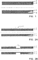
- FIG 2A schematically shows a thermally insulated transporting tube 1, comparable to figure 1 , which at a certain position P needs to be provided with a water barrier according to the present invention.
- the way in which this position P has been determined is of no relevance to the present invention.
- Figure 2B schematically illustrates that, as first step in a method according to the present invention, the outer tube 2 and the PU-foam 4 have been removed over the full circumference of the transporting tube 1 and over an axial length L, which is not critical and which for instance may be chosen in the range from 5 to 30 cm. A larger length is also allowed, but will in general not be necessary for obtaining a better effect. A smaller length is also allowed, but it is wise to choose this length not too small. It is clearly visible that the transporting tube 1 is exposed in the area where the insulation casing has been removed.
- a transporting conduit which may be many kilometres long, is built in situ from prefabricated tube segments. These tube segments have a certain standard length which may for instance be 6 meter but which also may be 20 meter. They are manufactured in a plant, transported to the building site and welded together there. On manufacture in the plant, both ends of the tube segment are always left free, or the insulating casing is, after manufacture, removed at each end over a length of for instance about 20 cm. This removal may be done in the plant, or at the building site.
- FIG 3A shows two end parts of two transport tube segments 21, 31, which are placed opposite each other to be welded together.
- Each tube segment 21, 31 is provided with an insulation casing with an outer tube 22, 32 and a PU-foam filling 24, 34 of the annular intermediate space 23, 33.
- the insulating casing is removed, or in any case absent, over a length L2 and L3, respectively, of for instance about 20 cm.
- Figure 3B shows the same two end segments of the same two transporting tube segments 21, 31 after the transporting tubes segments 21, 31 have been welded together by a weld 5.
- a thermoplastic shrink sleeve 40 is arranged over the area where the insulation casing is absent.
- the shrink sleeve 40 has an axial length larger than the length L of the interruption in the insulation casing, and has an inner diameter that is slightly larger than the outer diameter of the outer tube 2.
- the thickness is for instance about 3 mm - 50 mm.
- a cylindrical sleeve as shrinking sleeve.
- This cylindrical sleeve is shifted on one of the tube segments before the tube segments are welded together, and in that case the cylindrical sleeve can simply be shifted in axial direction after welding in order to be placed over the interruption zone.
- the shrinking sleeve is formed by folding a piece of plate material around the tube. It is of course also possible to fold a piece of plate material around the tube in the case of the situation of figures 3A-3B .
- Figures 4A-4B schematically illustrate the axial shifting of a cylindrical sleeve 40.
- FIGS 5A-5C schematically illustrate winding a plate 50 in order to thus form a sleeve 40.
- the ends of the plate 50 that overlap each other are fixed together, for instance by welding.
- the shrink sleeve 40 is heated, to a temperature fitting to the material of the shrink sleeve 40, to thus make the shrink sleeve shrink.
- the diameter of the shrink sleeve decreases here. The diameter reduction may for instance be 10% or more, depending on the chosen material.
- the original inner diameter of the shrink sleeve 40 was about equal to ( figure 5C ) or less than 10% larger than ( figure 4A ) the outer diameter of the outer tube 2, so that after executing the heating step the shrink sleeve 40 is clamped firmly around the outer tube 2 (see figure 6A ).
- the axial end edges of the shrink sleeve 40 are subsequently welded to the outer tube 2, in order to obtain a good watertight joint between the outer tube 2 and the shrink sleeve 40 (see figure 6B ).
- the welding method used herein is not critical, but as an example the materials can be melted together by means of a hot gas, or melted plastic material in the form of an extrusion seam may be supplied.
- annular space 60 is filled with a hardening material 70. Filling is done in liquid form. To this end, first a hole (or multiple holes) is made in the shrink sleeve 40, through which the liquid material is inserted. This hole may be made at the upper side, so that the liquid material can simply be poured into the annular shape 60 through a funnel.
- the hole is made at the lower side, so that the liquid material is injected or pumped up into the annular shape 60; in this case, a hole (or multiple holes) may then also be made at the upper side to allow air to escape from the annular space 60.
- venting is stimulated by connecting a vacuum pump to the hole at the upper side. After hardening of the filling material 70, the hole is/the holes are closed by welding.
- the filling material is selected to have the following properties after hardening:
- the material of the shrink sleeve is not critical. Suitable examples of thermoplastic materials which are weldable are for instance PE (polyethene / polyethylene), PP (polypropene / polypropylene), PVC (polyvinylchloride), PVDF (polyvinylidene fluoride), E-CTFE (Ethylene - Chloridetrifluorethylene - Copolymere), PFA (perfluoroalkoxy).
- PE polyethene / polyethylene
- PP polypropene / polypropylene
- PVC polyvinylchloride
- PVDF polyvinylidene fluoride
- E-CTFE Ethylene - Chloridetrifluorethylene - Copolymere
- PFA perfluoroalkoxy
- the inner surface of the sleeve 40 is preferably pre-treated.
- the pre-treatment comprises for instance, and preferably, the application of a fibre layer, preferably a glass fibre layer, as described in Dutch patent 1033399 .
- the sleeve 40 (implemented as cylinder or as bent plate) is made of an at least partially transparent material, so that it is possible to visually follow the filling of the annular shape 60 with the filling material 70.
- the invention further provides some further elaborations for achieving an even better result.
- the filling material 70 not only has the function of counteracting migration of water through the insulation foam, but also has a function of protecting and insulating the transporting tube 1. Furthermore, the filling material 70 (resin) is rather expensive. In order to save costs, the present invention proposes that the filling material 70, in any case at the moment of application, consists of a liquid fraction and a grain-shaped fraction. The liquid fraction then is the hardening PU-resin discussed in the above.
- the grain-shaped material is primarily chosen for having a good adherence with this resin. Depending on the filling degree chosen, i.e. the volume of liquid resin that is replaced by volume grain-shaped material, a saving of costs is achieved.
- suitable materials to be used as grain-shaped fraction are sand, fine gravel, gypsum, stone wool, porous stone, lava stone, wood chips, cork.
- the insulation value achieved will also depend on the grain-shaped material chosen. Particularly advantageous results have been obtained with using cork.
- a suitable size for the grains is a diameter of a few millimetres.
Landscapes
- Engineering & Computer Science (AREA)
- General Engineering & Computer Science (AREA)
- Mechanical Engineering (AREA)
- Thermal Insulation (AREA)
- Cable Accessories (AREA)
- Insulating Bodies (AREA)
Abstract
Description
- The invention relates in general to insulated tubes. More particularly, the invention relates to tubes which, in their operative condition, are buried in the ground, and the invention will be specifically explained for such tubes, but the invention is also applicable to non-buried tubes.
- It is fairly common that transport tubes for transporting a gas or liquid are buried in the ground, in which case the depth below ground surface may be many meters. Especially when the medium to be transported has a temperature which deviates substantially from the ground temperature, for instance in the case of a warm water network or a steam network, or for other reasons, the tube is then provided with a thermally insulating casing. The insulating casing may also have the function of electrical insulation or sound insulation. The material of the tube is often steel, but may also be plastic, for instance PE or PP. Especially PE 100 is an often used material. As schematically illustrated in
figure 1 , asecond tube 2 is arranged around thetransporting tube 1, which second tube will be indicated as "outer tube". The inner diameter of theouter tube 2 is larger than the outer diameter of the transportingtube 1, and theannular space 3 between both tubes is filled with aninsulation material 4, which usually is a PU-foam. The system is designed such that there is good adherence between the PU-foam 4 and thetransporting tube 1, and such that there is a good adherence between the PU-foam 4 and theouter tube 2; if necessary, to this end a pre-treatment has been applied to the inner surface of theouter tube 2 and/or to the outer surface of thetransporting tube 1, but this pre-treatment is known per se and is outside the context of the present invention, so that it will not be discussed further. It is noted that, in the case of asteel transporting tube 1, the outer surface of the transportingtube 1 is provided with a corrosion resistant coating, also known per se. - It should be clear that the thickness of the PU-
foam 4 layer is chosen depending on the insulation requirements. -
GB-2.319.316 - When the transporting tube is lying in a moist surroundings, such as for instance when the ground is moist or when the tube is lying in the ground water, and when for any reason there is damage (leakage) in the
outer tube 2, water or moisture can reach the PU-foam 4 through theouter tube 2. The penetrating moisture/water quickly migrates through the entire insulation material, which becomes saturated. As a result, in any case the insulating properties of the PU-foam 4 will reduce drastically. Above that, the PU-foam 4 itself may be affected by the water/moisture; PU-foam usually is not resistant against hydrolysis. Then, a consequence is that, even in the case of a relatively small leakage in theouter tube 2, the complete insulation casing (outer tube 2 plus PU-foam 4) must be replaced, in any case over a certain length. The more time has lapsed between the occurrence of the leakage and the repair, the larger the length that needs to be replaced. In case thetransporting tube 1 is a steel tube, thetransporting tube 1 may in the meantime have been affected by the moisture; in that case it is even necessary to replace the entire tube, in any case over a certain length. This may also be necessary if replacing the insulation casing is more labour intensive and expensive than replacing a part of the entire tube. A complicating factor here is that it is not always clear, or easy to assess, how far the damage has extended itself in the meantime and thus how much tube one needs to replace, so that out of necessity one often replaces an unnecessarily large part of the tube. -
GB-2.319.316 - An important objective of the present invention is eliminating or at least reducing the said problem. This objective is obtained by the measures of
claim 1. Briefly said, a water barrier is arranged in one or multiple positions, which interrupts the PU-foam in axial direction (i.e. length direction of the transporting tube). Any moisture that possibly penetrated the PU-foam can then migrate in axial direction not further than up to the first water barrier. Not only does this actually prevent a further extension of the damage, but it is now also possible to indicate with certainty a place where the damage has not passed. The shorter the mutual distance between successive water barriers, the shorter the length of the tube parts which should be replaced. - These and other aspects, features and advantages of the present invention will be further clarified by the following description of one or more exemplary embodiments with reference to the drawings, in which same reference numerals indicate same or similar parts, in which indications "under/above", "higher/lower", "left/right" etcetera exclusively relate to the orientation shown in the figures, and in which:
-
figure 1 shows a schematic longitudinal cross-section of a part of an insulated transporting tube; -
figures 2A-2D schematically illustrate the process of applying a water barrier in an insulated transporting tube; -
figures 3A-3B schematically illustrate welding of tube segments; -
figures 4A-4B schematically illustrate axially shifting a cylindrical sleeve; -
figures 5A-5C schematically illustrate shaping a sleeve by winding a plate; -
figures 6A-6B schematically illustrate the process of filling the sleeve; -
figure 7 schematically illustrates a water barrier. -
Figure 2A schematically shows a thermally insulatedtransporting tube 1, comparable tofigure 1 , which at a certain position P needs to be provided with a water barrier according to the present invention. The way in which this position P has been determined is of no relevance to the present invention. -
Figure 2B schematically illustrates that, as first step in a method according to the present invention, theouter tube 2 and the PU-foam 4 have been removed over the full circumference of thetransporting tube 1 and over an axial length L, which is not critical and which for instance may be chosen in the range from 5 to 30 cm. A larger length is also allowed, but will in general not be necessary for obtaining a better effect. A smaller length is also allowed, but it is wise to choose this length not too small. It is clearly visible that thetransporting tube 1 is exposed in the area where the insulation casing has been removed. - The situation of
figures 2A and 2B discussed above can occur in the case of existing tubes, even in the case of tubes which are already buried (repair), but can also occur in the case of new tubes that need to be placed (preventively). - A transporting conduit, which may be many kilometres long, is built in situ from prefabricated tube segments. These tube segments have a certain standard length which may for instance be 6 meter but which also may be 20 meter. They are manufactured in a plant, transported to the building site and welded together there. On manufacture in the plant, both ends of the tube segment are always left free, or the insulating casing is, after manufacture, removed at each end over a length of for instance about 20 cm. This removal may be done in the plant, or at the building site.
-
Figure 3A shows two end parts of twotransport tube segments tube segment outer tube foam filling intermediate space 23, 33. At the end parts, the insulating casing is removed, or in any case absent, over a length L2 and L3, respectively, of for instance about 20 cm. -
Figure 3B shows the same two end segments of the same twotransporting tube segments transporting tubes segments weld 5. - It may be clear that the situation now achieved is comparable to the situation of
figure 2B , i.e. acontiguous transporting tube 21/31 of which the insulating casing is interrupted over a length L. - As next step in the method according to the present invention, a
thermoplastic shrink sleeve 40 is arranged over the area where the insulation casing is absent. Theshrink sleeve 40 has an axial length larger than the length L of the interruption in the insulation casing, and has an inner diameter that is slightly larger than the outer diameter of theouter tube 2. Depending on circumstances, the thickness is for instance about 3 mm - 50 mm. - In the situation of
figures 3A-3B , where new tube segments are welded together or wherein a repair segment is welded into an existing conduit, one can use a cylindrical sleeve as shrinking sleeve. This cylindrical sleeve is shifted on one of the tube segments before the tube segments are welded together, and in that case the cylindrical sleeve can simply be shifted in axial direction after welding in order to be placed over the interruption zone. In the situation offigures 2A-2B , where a piece of casing is removed from an existing tube, the shrinking sleeve is formed by folding a piece of plate material around the tube. It is of course also possible to fold a piece of plate material around the tube in the case of the situation offigures 3A-3B . -
Figures 4A-4B schematically illustrate the axial shifting of acylindrical sleeve 40. -
Figures 5A-5C schematically illustrate winding aplate 50 in order to thus form asleeve 40. The ends of theplate 50 that overlap each other are fixed together, for instance by welding. - As a next step in the method according to the present invention, the
shrink sleeve 40 is heated, to a temperature fitting to the material of theshrink sleeve 40, to thus make the shrink sleeve shrink. The diameter of the shrink sleeve decreases here. The diameter reduction may for instance be 10% or more, depending on the chosen material. The original inner diameter of theshrink sleeve 40 was about equal to (figure 5C ) or less than 10% larger than (figure 4A ) the outer diameter of theouter tube 2, so that after executing the heating step theshrink sleeve 40 is clamped firmly around the outer tube 2 (seefigure 6A ). - Preferably, the axial end edges of the
shrink sleeve 40 are subsequently welded to theouter tube 2, in order to obtain a good watertight joint between theouter tube 2 and the shrink sleeve 40 (seefigure 6B ). - The welding method used herein is not critical, but as an example the materials can be melted together by means of a hot gas, or melted plastic material in the form of an extrusion seam may be supplied.
- Between the shrunk
shrink sleeve 40 and thetransport tube 1, anannular space 60 has now come into being, which is confined in axial direction by theouter tube 2 and the PU-foam 4. As next step in the method according to the present invention, thisannular space 60 is filled with a hardeningmaterial 70. Filling is done in liquid form. To this end, first a hole (or multiple holes) is made in theshrink sleeve 40, through which the liquid material is inserted. This hole may be made at the upper side, so that the liquid material can simply be poured into theannular shape 60 through a funnel. It is also possible that the hole (or multiple holes) is made at the lower side, so that the liquid material is injected or pumped up into theannular shape 60; in this case, a hole (or multiple holes) may then also be made at the upper side to allow air to escape from theannular space 60. Preferably, venting is stimulated by connecting a vacuum pump to the hole at the upper side. After hardening of the fillingmaterial 70, the hole is/the holes are closed by welding. - The filling material is selected to have the following properties after hardening:
- a- a good connection to the material of the
transport tube 1; - b- a good connection to the PU-
foam 4; - c- a good connection to the material of the
shrink sleeve 40; - d- solid and watertight
- It is noted that the material of the shrink sleeve is not critical. Suitable examples of thermoplastic materials which are weldable are for instance PE (polyethene / polyethylene), PP (polypropene / polypropylene), PVC (polyvinylchloride), PVDF (polyvinylidene fluoride), E-CTFE (Ethylene - Chloridetrifluorethylene - Copolymere), PFA (perfluoroalkoxy). For a good connection tot the PU-resin, the shrink sleeve is preferably provided with a glass fibre maze at its inner surface. The good connection with the material of the sleeve and with the material of the transport tube prevents a gap from existing where water could creep through. In tests, performed by the "Automatic Adhesion Tester" of the mark: DeFelsko / Positest At-A; sn.AT06631, according tot ASTM D4541/D7234, ISO 4624/16276-1, AS / NZS 1580.408.5, with pulling dollies having a diameter of 20 mm, tearing strengths have been realised of at least 3.5 MPa.
- For increasing the adhesion strength between the sleeve 40 (implemented as cylinder or as bent plate) and the filling
material 70, the inner surface of thesleeve 40 is preferably pre-treated. The pre-treatment comprises for instance, and preferably, the application of a fibre layer, preferably a glass fibre layer, as described in Dutch patent1033399 . - It is further preferred that the sleeve 40 (implemented as cylinder or as bent plate) is made of an at least partially transparent material, so that it is possible to visually follow the filling of the
annular shape 60 with the fillingmaterial 70. - The invention further provides some further elaborations for achieving an even better result.
- The filling
material 70 not only has the function of counteracting migration of water through the insulation foam, but also has a function of protecting and insulating the transportingtube 1. Furthermore, the filling material 70 (resin) is rather expensive. In order to save costs, the present invention proposes that the fillingmaterial 70, in any case at the moment of application, consists of a liquid fraction and a grain-shaped fraction. The liquid fraction then is the hardening PU-resin discussed in the above. The grain-shaped material is primarily chosen for having a good adherence with this resin. Depending on the filling degree chosen, i.e. the volume of liquid resin that is replaced by volume grain-shaped material, a saving of costs is achieved. Advantageous examples of suitable materials to be used as grain-shaped fraction are sand, fine gravel, gypsum, stone wool, porous stone, lava stone, wood chips, cork. - The insulation value achieved will also depend on the grain-shaped material chosen. Particularly advantageous results have been obtained with using cork.
- It is recommendable for the grains not to be chosen too large. A suitable size for the grains is a diameter of a few millimetres.
- It is possible to mix the grain-shaped fraction and the liquid fraction with each other before the filling
material 70 is introduced into theannular space 60. However, it is preferred to first introduce the grains into theannular space 60, for instance by suction, such that theannular space 60 is almost entirely filled with the grains, and to then fill the spaces remaining between the grains with the liquid resin. - It should be clear to a person skilled in the art that the invention is not limited to the exemplary embodiments discussed in the above, but that several variations and modifications are possible within the protective scope of the invention as defined in the attached claims. Even if certain features are mentioned in different dependent claims, the present invention also relates to an embodiment which has these features in common. Features which are not explicitly described as being essential may also be omitted. Possible reference numerals used in a claim should not be explained as limiting for the scope of that claim.
Claims (7)
- Thermally insulated transport tube (1), provided with an outer tube (2) arranged around the transport tube (1) and an insulation foam (4) arranged in the annular space (3) between the transport tube (1) and the outer tube (2), wherein, in one or multiple positions, a water barrier is arranged which interrupts the insulation foam in axial direction.
- Thermally insulated transport tube (1) according to claim 1, wherein the water barrier is formed by a solid and water-tight substance (70) that adheres well to the transport tube and to the insulation foam (4).
- Thermally insulated transport tube (1) according to claim 2, wherein at said at least one location a shrinking sleeve (40) is attached to the outer tube (2) and wherein said solid and water-tight substance (70) also adheres well to this shrinking sleeve (40).
- Thermally insulated transport tube (1) according to claim 2 or 3, wherein the solid and water-tight substance (70) comprises a grain-shaped material embedded therein.
- Thermally insulated transport tube (1) according to claim 4, wherein the grain-shaped material comprises any one of sand, fine gravel, gypsum, stone wool, porous stone, lava stone, wood chips, or cork.
- Thermally insulated transport tube (1) according to any of the previous claims, wherein the solid and water-tight substance (70) comprises a hardened resin.
- Thermally insulated transport tube (1) according to any of the previous claims, wherein the solid and water-tight substance (70) comprises a hardened PU-resin.
Applications Claiming Priority (3)
| Application Number | Priority Date | Filing Date | Title |
|---|---|---|---|
| NL1040210A NL1040210C2 (en) | 2013-05-14 | 2013-05-14 | METHOD FOR AGAINST MOISTURE MIGRATION IN A THERMALLY INSULATED TUBE AND THE TUBE MANUFACTURED IN THIS METHOD. |
| EP14727950.9A EP2997293B1 (en) | 2013-05-14 | 2014-05-13 | Method to counteract moisture migration in a thermally insulated tube, as well as a tube manufactured according to this method |
| PCT/NL2014/000016 WO2014185772A2 (en) | 2013-05-14 | 2014-05-13 | Method to counteract moisture migration in a thermally insulated tube, as well as a tube manufactured according to this method |
Related Parent Applications (1)
| Application Number | Title | Priority Date | Filing Date |
|---|---|---|---|
| EP14727950.9A Division EP2997293B1 (en) | 2013-05-14 | 2014-05-13 | Method to counteract moisture migration in a thermally insulated tube, as well as a tube manufactured according to this method |
Publications (3)
| Publication Number | Publication Date |
|---|---|
| EP3492797A1 true EP3492797A1 (en) | 2019-06-05 |
| EP3492797C0 EP3492797C0 (en) | 2024-09-18 |
| EP3492797B1 EP3492797B1 (en) | 2024-09-18 |
Family
ID=49170783
Family Applications (2)
| Application Number | Title | Priority Date | Filing Date |
|---|---|---|---|
| EP14727950.9A Active EP2997293B1 (en) | 2013-05-14 | 2014-05-13 | Method to counteract moisture migration in a thermally insulated tube, as well as a tube manufactured according to this method |
| EP19000002.6A Active EP3492797B1 (en) | 2013-05-14 | 2014-05-13 | Thermally insulated tube with reduced moisture migration |
Family Applications Before (1)
| Application Number | Title | Priority Date | Filing Date |
|---|---|---|---|
| EP14727950.9A Active EP2997293B1 (en) | 2013-05-14 | 2014-05-13 | Method to counteract moisture migration in a thermally insulated tube, as well as a tube manufactured according to this method |
Country Status (3)
| Country | Link |
|---|---|
| EP (2) | EP2997293B1 (en) |
| NL (1) | NL1040210C2 (en) |
| WO (1) | WO2014185772A2 (en) |
Citations (11)
| Publication number | Priority date | Publication date | Assignee | Title |
|---|---|---|---|---|
| EP0070065A1 (en) * | 1981-07-02 | 1983-01-19 | Wavin B.V. | Pipe coupler for insulated pipes and method for fitting same |
| WO1984003346A1 (en) * | 1983-02-24 | 1984-08-30 | Ania Bv | Method of securing a shrink sleeve upon the outer ends of the insulating jacket of a thermally insulated conduit |
| EP0188363A1 (en) * | 1985-01-14 | 1986-07-23 | Shaw Industries Ltd. | Preinsulated pipeline joint |
| DE3720577A1 (en) * | 1986-07-31 | 1988-02-04 | Meier Schenk Ag | Weld sleeve for producing a pipe connection, and use of said weld sleeve |
| GB2319316A (en) | 1996-11-14 | 1998-05-20 | Shaw Ind Ltd | Heat shrinkable member for connecting tubular sections |
| DE10211703A1 (en) * | 2002-03-16 | 2003-09-25 | Brugg Rohrsysteme Gmbh | Creation of moisture tight joint between two pipe ends, particularly district heating pipes, involves winding of wave-form heating wires onto pipe ends, location of socket over pipe ends and heating wires |
| WO2003095887A1 (en) * | 2002-05-08 | 2003-11-20 | Socotherm S.P.A. | Method for the field insulation of connecting joints for fluid transport pipelines |
| US6978807B1 (en) * | 2005-03-25 | 2005-12-27 | Thermacor Process, Lp | Water stop for a line installation in a pre-insulated pipeline |
| US7028717B1 (en) * | 2005-03-25 | 2006-04-18 | Thermacor Process, Lp | Water stop for a loop installation in a pre-insulated pipeline |
| NL1033399C2 (en) | 2007-02-15 | 2008-08-18 | Nederlandse Gasunie Nv | Coating method for welded joint between coated metal pipes, comprises applying primer to exposed area and injecting plastic into space defined by tubular sheet of fibrous material |
| WO2012051719A1 (en) * | 2010-10-22 | 2012-04-26 | Shawcor Ltd. | Non-crosslinked shrinkable casing member for forming a connection between tubular sections and method of forming said connection by induction fusion |
-
2013
- 2013-05-14 NL NL1040210A patent/NL1040210C2/en active
-
2014
- 2014-05-13 WO PCT/NL2014/000016 patent/WO2014185772A2/en not_active Ceased
- 2014-05-13 EP EP14727950.9A patent/EP2997293B1/en active Active
- 2014-05-13 EP EP19000002.6A patent/EP3492797B1/en active Active
Patent Citations (11)
| Publication number | Priority date | Publication date | Assignee | Title |
|---|---|---|---|---|
| EP0070065A1 (en) * | 1981-07-02 | 1983-01-19 | Wavin B.V. | Pipe coupler for insulated pipes and method for fitting same |
| WO1984003346A1 (en) * | 1983-02-24 | 1984-08-30 | Ania Bv | Method of securing a shrink sleeve upon the outer ends of the insulating jacket of a thermally insulated conduit |
| EP0188363A1 (en) * | 1985-01-14 | 1986-07-23 | Shaw Industries Ltd. | Preinsulated pipeline joint |
| DE3720577A1 (en) * | 1986-07-31 | 1988-02-04 | Meier Schenk Ag | Weld sleeve for producing a pipe connection, and use of said weld sleeve |
| GB2319316A (en) | 1996-11-14 | 1998-05-20 | Shaw Ind Ltd | Heat shrinkable member for connecting tubular sections |
| DE10211703A1 (en) * | 2002-03-16 | 2003-09-25 | Brugg Rohrsysteme Gmbh | Creation of moisture tight joint between two pipe ends, particularly district heating pipes, involves winding of wave-form heating wires onto pipe ends, location of socket over pipe ends and heating wires |
| WO2003095887A1 (en) * | 2002-05-08 | 2003-11-20 | Socotherm S.P.A. | Method for the field insulation of connecting joints for fluid transport pipelines |
| US6978807B1 (en) * | 2005-03-25 | 2005-12-27 | Thermacor Process, Lp | Water stop for a line installation in a pre-insulated pipeline |
| US7028717B1 (en) * | 2005-03-25 | 2006-04-18 | Thermacor Process, Lp | Water stop for a loop installation in a pre-insulated pipeline |
| NL1033399C2 (en) | 2007-02-15 | 2008-08-18 | Nederlandse Gasunie Nv | Coating method for welded joint between coated metal pipes, comprises applying primer to exposed area and injecting plastic into space defined by tubular sheet of fibrous material |
| WO2012051719A1 (en) * | 2010-10-22 | 2012-04-26 | Shawcor Ltd. | Non-crosslinked shrinkable casing member for forming a connection between tubular sections and method of forming said connection by induction fusion |
Also Published As
| Publication number | Publication date |
|---|---|
| WO2014185772A3 (en) | 2015-02-26 |
| WO2014185772A2 (en) | 2014-11-20 |
| EP3492797C0 (en) | 2024-09-18 |
| NL1040210C2 (en) | 2014-11-24 |
| EP2997293B1 (en) | 2019-01-09 |
| EP2997293A2 (en) | 2016-03-23 |
| EP3492797B1 (en) | 2024-09-18 |
Similar Documents
| Publication | Publication Date | Title |
|---|---|---|
| KR102075320B1 (en) | Immersion Tube for repairing pipeline using hot-melt and Method for manufacturing the immersion tube | |
| NO171615B (en) | HEAT-INSULATING DEVICE FOR UNDERGROUND CONDITIONS, AND PROCEDURES FOR PLACING THE HEAT-INSULATING DEVICE | |
| AU2016221437B2 (en) | Subsea pipe-in-pipe structures | |
| NO325772B1 (en) | Process for the manufacture of stalrups with thermal insulation for undersea pipelines | |
| EP1504214A1 (en) | Method for the field insulation of connecting joints for fluid transport pipelines | |
| JP5501664B2 (en) | Seismic waterproof structure for existing pipes | |
| EP3492797B1 (en) | Thermally insulated tube with reduced moisture migration | |
| US10436350B1 (en) | Trenchless pipe-laying | |
| RU2398155C2 (en) | Procedure for anti-corrosion insulation of welding joint of pipeline and facility for its implementation | |
| AU2017270651A1 (en) | Method for connecting two unitary elements of a conduit for transporting fluids by means of a sleeve | |
| EP3419812B1 (en) | Method for producing single insulated pipes | |
| CN103574231B (en) | A kind of method of construction of thermal insulation of thermal insulation pipeline joint | |
| SE469015B (en) | PLASTIC SHRUFF MUG FOR TWO ROOM END | |
| CN105299385A (en) | Thermal insulation pipe with polyurethane and polyethylene bridging substances and manufacturing method | |
| CN201198928Y (en) | Seal device of building wall through hole with guarding tube | |
| WO2015147679A1 (en) | Method for thermally insulating welded joints of pre-insulated pipes | |
| RU2483851C1 (en) | Tube weld assembly and method of its making | |
| RU114503U1 (en) | FIXED BRACKET WITH POLYURETHANE INSULATION | |
| KR101370621B1 (en) | Method for constructing repair of double ins ulation pipe | |
| CN201982883U (en) | Polyurethane heat insulation joint for steel pipe protect | |
| RU2696653C2 (en) | Complex isolation of pipeline weld joint and method of its production | |
| KR101044931B1 (en) | How to connect watertight hot water pipes | |
| KR20170031876A (en) | Method for constru cting repair of connection in double insulation pipe using outer jacket | |
| KR100405203B1 (en) | distributing pipe | |
| JP5783089B2 (en) | Method and apparatus for anticorrosion coating of steel weld joint |
Legal Events
| Date | Code | Title | Description |
|---|---|---|---|
| PUAI | Public reference made under article 153(3) epc to a published international application that has entered the european phase |
Free format text: ORIGINAL CODE: 0009012 |
|
| STAA | Information on the status of an ep patent application or granted ep patent |
Free format text: STATUS: THE APPLICATION HAS BEEN PUBLISHED |
|
| AC | Divisional application: reference to earlier application |
Ref document number: 2997293 Country of ref document: EP Kind code of ref document: P |
|
| AK | Designated contracting states |
Kind code of ref document: A1 Designated state(s): AL AT BE BG CH CY CZ DE DK EE ES FI FR GB GR HR HU IE IS IT LI LT LU LV MC MK MT NL NO PL PT RO RS SE SI SK SM TR |
|
| STAA | Information on the status of an ep patent application or granted ep patent |
Free format text: STATUS: REQUEST FOR EXAMINATION WAS MADE |
|
| 17P | Request for examination filed |
Effective date: 20191205 |
|
| RBV | Designated contracting states (corrected) |
Designated state(s): AL AT BE BG CH CY CZ DE DK EE ES FI FR GB GR HR HU IE IS IT LI LT LU LV MC MK MT NL NO PL PT RO RS SE SI SK SM TR |
|
| STAA | Information on the status of an ep patent application or granted ep patent |
Free format text: STATUS: EXAMINATION IS IN PROGRESS |
|
| 17Q | First examination report despatched |
Effective date: 20210705 |
|
| GRAP | Despatch of communication of intention to grant a patent |
Free format text: ORIGINAL CODE: EPIDOSNIGR1 |
|
| STAA | Information on the status of an ep patent application or granted ep patent |
Free format text: STATUS: GRANT OF PATENT IS INTENDED |
|
| INTG | Intention to grant announced |
Effective date: 20230522 |
|
| GRAJ | Information related to disapproval of communication of intention to grant by the applicant or resumption of examination proceedings by the epo deleted |
Free format text: ORIGINAL CODE: EPIDOSDIGR1 |
|
| STAA | Information on the status of an ep patent application or granted ep patent |
Free format text: STATUS: EXAMINATION IS IN PROGRESS |
|
| GRAP | Despatch of communication of intention to grant a patent |
Free format text: ORIGINAL CODE: EPIDOSNIGR1 |
|
| STAA | Information on the status of an ep patent application or granted ep patent |
Free format text: STATUS: GRANT OF PATENT IS INTENDED |
|
| INTC | Intention to grant announced (deleted) | ||
| INTG | Intention to grant announced |
Effective date: 20240125 |
|
| GRAS | Grant fee paid |
Free format text: ORIGINAL CODE: EPIDOSNIGR3 |
|
| GRAA | (expected) grant |
Free format text: ORIGINAL CODE: 0009210 |
|
| STAA | Information on the status of an ep patent application or granted ep patent |
Free format text: STATUS: THE PATENT HAS BEEN GRANTED |
|
| AC | Divisional application: reference to earlier application |
Ref document number: 2997293 Country of ref document: EP Kind code of ref document: P |
|
| AK | Designated contracting states |
Kind code of ref document: B1 Designated state(s): AL AT BE BG CH CY CZ DE DK EE ES FI FR GB GR HR HU IE IS IT LI LT LU LV MC MK MT NL NO PL PT RO RS SE SI SK SM TR |
|
| REG | Reference to a national code |
Ref country code: GB Ref legal event code: FG4D |
|
| REG | Reference to a national code |
Ref country code: CH Ref legal event code: EP |
|
| REG | Reference to a national code |
Ref country code: DE Ref legal event code: R096 Ref document number: 602014090891 Country of ref document: DE |
|
| REG | Reference to a national code |
Ref country code: IE Ref legal event code: FG4D |
|
| U01 | Request for unitary effect filed |
Effective date: 20241014 |
|
| U07 | Unitary effect registered |
Designated state(s): AT BE BG DE DK EE FI FR IT LT LU LV MT NL PT RO SE SI Effective date: 20241128 |
|
| PG25 | Lapsed in a contracting state [announced via postgrant information from national office to epo] |
Ref country code: NO Free format text: LAPSE BECAUSE OF FAILURE TO SUBMIT A TRANSLATION OF THE DESCRIPTION OR TO PAY THE FEE WITHIN THE PRESCRIBED TIME-LIMIT Effective date: 20241218 |
|
| PG25 | Lapsed in a contracting state [announced via postgrant information from national office to epo] |
Ref country code: GR Free format text: LAPSE BECAUSE OF FAILURE TO SUBMIT A TRANSLATION OF THE DESCRIPTION OR TO PAY THE FEE WITHIN THE PRESCRIBED TIME-LIMIT Effective date: 20241219 |
|
| PG25 | Lapsed in a contracting state [announced via postgrant information from national office to epo] |
Ref country code: HR Free format text: LAPSE BECAUSE OF FAILURE TO SUBMIT A TRANSLATION OF THE DESCRIPTION OR TO PAY THE FEE WITHIN THE PRESCRIBED TIME-LIMIT Effective date: 20240918 |
|
| PG25 | Lapsed in a contracting state [announced via postgrant information from national office to epo] |
Ref country code: RS Free format text: LAPSE BECAUSE OF FAILURE TO SUBMIT A TRANSLATION OF THE DESCRIPTION OR TO PAY THE FEE WITHIN THE PRESCRIBED TIME-LIMIT Effective date: 20241218 |
|
| PG25 | Lapsed in a contracting state [announced via postgrant information from national office to epo] |
Ref country code: RS Free format text: LAPSE BECAUSE OF FAILURE TO SUBMIT A TRANSLATION OF THE DESCRIPTION OR TO PAY THE FEE WITHIN THE PRESCRIBED TIME-LIMIT Effective date: 20241218 Ref country code: NO Free format text: LAPSE BECAUSE OF FAILURE TO SUBMIT A TRANSLATION OF THE DESCRIPTION OR TO PAY THE FEE WITHIN THE PRESCRIBED TIME-LIMIT Effective date: 20241218 Ref country code: HR Free format text: LAPSE BECAUSE OF FAILURE TO SUBMIT A TRANSLATION OF THE DESCRIPTION OR TO PAY THE FEE WITHIN THE PRESCRIBED TIME-LIMIT Effective date: 20240918 Ref country code: GR Free format text: LAPSE BECAUSE OF FAILURE TO SUBMIT A TRANSLATION OF THE DESCRIPTION OR TO PAY THE FEE WITHIN THE PRESCRIBED TIME-LIMIT Effective date: 20241219 |
|
| U1N | Appointed representative for the unitary patent procedure changed after the registration of the unitary effect |
Representative=s name: PATENTWERK B.V.; NL |
|
| PG25 | Lapsed in a contracting state [announced via postgrant information from national office to epo] |
Ref country code: IS Free format text: LAPSE BECAUSE OF FAILURE TO SUBMIT A TRANSLATION OF THE DESCRIPTION OR TO PAY THE FEE WITHIN THE PRESCRIBED TIME-LIMIT Effective date: 20250118 |
|
| PG25 | Lapsed in a contracting state [announced via postgrant information from national office to epo] |
Ref country code: SM Free format text: LAPSE BECAUSE OF FAILURE TO SUBMIT A TRANSLATION OF THE DESCRIPTION OR TO PAY THE FEE WITHIN THE PRESCRIBED TIME-LIMIT Effective date: 20240918 |
|
| PG25 | Lapsed in a contracting state [announced via postgrant information from national office to epo] |
Ref country code: ES Free format text: LAPSE BECAUSE OF FAILURE TO SUBMIT A TRANSLATION OF THE DESCRIPTION OR TO PAY THE FEE WITHIN THE PRESCRIBED TIME-LIMIT Effective date: 20240918 |
|
| PG25 | Lapsed in a contracting state [announced via postgrant information from national office to epo] |
Ref country code: CZ Free format text: LAPSE BECAUSE OF FAILURE TO SUBMIT A TRANSLATION OF THE DESCRIPTION OR TO PAY THE FEE WITHIN THE PRESCRIBED TIME-LIMIT Effective date: 20240918 Ref country code: PL Free format text: LAPSE BECAUSE OF FAILURE TO SUBMIT A TRANSLATION OF THE DESCRIPTION OR TO PAY THE FEE WITHIN THE PRESCRIBED TIME-LIMIT Effective date: 20240918 |
|
| PG25 | Lapsed in a contracting state [announced via postgrant information from national office to epo] |
Ref country code: SK Free format text: LAPSE BECAUSE OF FAILURE TO SUBMIT A TRANSLATION OF THE DESCRIPTION OR TO PAY THE FEE WITHIN THE PRESCRIBED TIME-LIMIT Effective date: 20240918 |
|
| U20 | Renewal fee for the european patent with unitary effect paid |
Year of fee payment: 12 Effective date: 20250527 |
|
| PLBE | No opposition filed within time limit |
Free format text: ORIGINAL CODE: 0009261 |
|
| STAA | Information on the status of an ep patent application or granted ep patent |
Free format text: STATUS: NO OPPOSITION FILED WITHIN TIME LIMIT |
|
| 26N | No opposition filed |
Effective date: 20250619 |
|
| REG | Reference to a national code |
Ref country code: CH Ref legal event code: H13 Free format text: ST27 STATUS EVENT CODE: U-0-0-H10-H13 (AS PROVIDED BY THE NATIONAL OFFICE) Effective date: 20251223 |
|
| PG25 | Lapsed in a contracting state [announced via postgrant information from national office to epo] |
Ref country code: CH Free format text: LAPSE BECAUSE OF NON-PAYMENT OF DUE FEES Effective date: 20250531 |
|
| GBPC | Gb: european patent ceased through non-payment of renewal fee |
Effective date: 20250513 |
|
| PG25 | Lapsed in a contracting state [announced via postgrant information from national office to epo] |
Ref country code: MC Free format text: LAPSE BECAUSE OF FAILURE TO SUBMIT A TRANSLATION OF THE DESCRIPTION OR TO PAY THE FEE WITHIN THE PRESCRIBED TIME-LIMIT Effective date: 20240918 |
|
| PG25 | Lapsed in a contracting state [announced via postgrant information from national office to epo] |
Ref country code: GB Free format text: LAPSE BECAUSE OF NON-PAYMENT OF DUE FEES Effective date: 20250513 |
|
| PG25 | Lapsed in a contracting state [announced via postgrant information from national office to epo] |
Ref country code: IE Free format text: LAPSE BECAUSE OF NON-PAYMENT OF DUE FEES Effective date: 20250513 |
|
| U20 | Renewal fee for the european patent with unitary effect paid |
Year of fee payment: 13 Effective date: 20260527 |
|
| PG25 | Lapsed in a contracting state [announced via postgrant information from national office to epo] |
Ref country code: CY Free format text: LAPSE BECAUSE OF FAILURE TO SUBMIT A TRANSLATION OF THE DESCRIPTION OR TO PAY THE FEE WITHIN THE PRESCRIBED TIME-LIMIT Effective date: 20240918 |