EP3492743A1 - Scroll-type fluid machine and method for assembling same - Google Patents
Scroll-type fluid machine and method for assembling same Download PDFInfo
- Publication number
- EP3492743A1 EP3492743A1 EP16910554.1A EP16910554A EP3492743A1 EP 3492743 A1 EP3492743 A1 EP 3492743A1 EP 16910554 A EP16910554 A EP 16910554A EP 3492743 A1 EP3492743 A1 EP 3492743A1
- Authority
- EP
- European Patent Office
- Prior art keywords
- main body
- scroll
- motor
- positioning
- unit
- Prior art date
- Legal status (The legal status is an assumption and is not a legal conclusion. Google has not performed a legal analysis and makes no representation as to the accuracy of the status listed.)
- Granted
Links
Images



Classifications
-
- F—MECHANICAL ENGINEERING; LIGHTING; HEATING; WEAPONS; BLASTING
- F04—POSITIVE - DISPLACEMENT MACHINES FOR LIQUIDS; PUMPS FOR LIQUIDS OR ELASTIC FLUIDS
- F04C—ROTARY-PISTON, OR OSCILLATING-PISTON, POSITIVE-DISPLACEMENT MACHINES FOR LIQUIDS; ROTARY-PISTON, OR OSCILLATING-PISTON, POSITIVE-DISPLACEMENT PUMPS
- F04C18/00—Rotary-piston pumps specially adapted for elastic fluids
- F04C18/02—Rotary-piston pumps specially adapted for elastic fluids of arcuate-engagement type, i.e. with circular translatory movement of co-operating members, each member having the same number of teeth or tooth-equivalents
- F04C18/0207—Rotary-piston pumps specially adapted for elastic fluids of arcuate-engagement type, i.e. with circular translatory movement of co-operating members, each member having the same number of teeth or tooth-equivalents both members having co-operating elements in spiral form
- F04C18/0215—Rotary-piston pumps specially adapted for elastic fluids of arcuate-engagement type, i.e. with circular translatory movement of co-operating members, each member having the same number of teeth or tooth-equivalents both members having co-operating elements in spiral form where only one member is moving
-
- F—MECHANICAL ENGINEERING; LIGHTING; HEATING; WEAPONS; BLASTING
- F01—MACHINES OR ENGINES IN GENERAL; ENGINE PLANTS IN GENERAL; STEAM ENGINES
- F01C—ROTARY-PISTON OR OSCILLATING-PISTON MACHINES OR ENGINES
- F01C21/00—Component parts, details or accessories not provided for in groups F01C1/00 - F01C20/00
- F01C21/007—General arrangements of parts; Frames and supporting elements
-
- F—MECHANICAL ENGINEERING; LIGHTING; HEATING; WEAPONS; BLASTING
- F01—MACHINES OR ENGINES IN GENERAL; ENGINE PLANTS IN GENERAL; STEAM ENGINES
- F01C—ROTARY-PISTON OR OSCILLATING-PISTON MACHINES OR ENGINES
- F01C21/00—Component parts, details or accessories not provided for in groups F01C1/00 - F01C20/00
- F01C21/10—Outer members for co-operation with rotary pistons; Casings
-
- F—MECHANICAL ENGINEERING; LIGHTING; HEATING; WEAPONS; BLASTING
- F04—POSITIVE - DISPLACEMENT MACHINES FOR LIQUIDS; PUMPS FOR LIQUIDS OR ELASTIC FLUIDS
- F04C—ROTARY-PISTON, OR OSCILLATING-PISTON, POSITIVE-DISPLACEMENT MACHINES FOR LIQUIDS; ROTARY-PISTON, OR OSCILLATING-PISTON, POSITIVE-DISPLACEMENT PUMPS
- F04C23/00—Combinations of two or more pumps, each being of rotary-piston or oscillating-piston type, specially adapted for elastic fluids; Pumping installations specially adapted for elastic fluids; Multi-stage pumps specially adapted for elastic fluids
- F04C23/02—Pumps characterised by combination with, or adaptation to, specific driving engines or motors
-
- F—MECHANICAL ENGINEERING; LIGHTING; HEATING; WEAPONS; BLASTING
- F04—POSITIVE - DISPLACEMENT MACHINES FOR LIQUIDS; PUMPS FOR LIQUIDS OR ELASTIC FLUIDS
- F04C—ROTARY-PISTON, OR OSCILLATING-PISTON, POSITIVE-DISPLACEMENT MACHINES FOR LIQUIDS; ROTARY-PISTON, OR OSCILLATING-PISTON, POSITIVE-DISPLACEMENT PUMPS
- F04C28/00—Control of, monitoring of, or safety arrangements for, pumps or pumping installations specially adapted for elastic fluids
- F04C28/18—Control of, monitoring of, or safety arrangements for, pumps or pumping installations specially adapted for elastic fluids characterised by varying the volume of the working chamber
- F04C28/22—Control of, monitoring of, or safety arrangements for, pumps or pumping installations specially adapted for elastic fluids characterised by varying the volume of the working chamber by changing the eccentricity between cooperating members
-
- F—MECHANICAL ENGINEERING; LIGHTING; HEATING; WEAPONS; BLASTING
- F04—POSITIVE - DISPLACEMENT MACHINES FOR LIQUIDS; PUMPS FOR LIQUIDS OR ELASTIC FLUIDS
- F04C—ROTARY-PISTON, OR OSCILLATING-PISTON, POSITIVE-DISPLACEMENT MACHINES FOR LIQUIDS; ROTARY-PISTON, OR OSCILLATING-PISTON, POSITIVE-DISPLACEMENT PUMPS
- F04C29/00—Component parts, details or accessories of pumps or pumping installations, not provided for in groups F04C18/00 - F04C28/00
- F04C29/0042—Driving elements, brakes, couplings, transmissions specially adapted for pumps
- F04C29/0085—Prime movers
-
- F—MECHANICAL ENGINEERING; LIGHTING; HEATING; WEAPONS; BLASTING
- F04—POSITIVE - DISPLACEMENT MACHINES FOR LIQUIDS; PUMPS FOR LIQUIDS OR ELASTIC FLUIDS
- F04C—ROTARY-PISTON, OR OSCILLATING-PISTON, POSITIVE-DISPLACEMENT MACHINES FOR LIQUIDS; ROTARY-PISTON, OR OSCILLATING-PISTON, POSITIVE-DISPLACEMENT PUMPS
- F04C2230/00—Manufacture
- F04C2230/60—Assembly methods
-
- F—MECHANICAL ENGINEERING; LIGHTING; HEATING; WEAPONS; BLASTING
- F04—POSITIVE - DISPLACEMENT MACHINES FOR LIQUIDS; PUMPS FOR LIQUIDS OR ELASTIC FLUIDS
- F04C—ROTARY-PISTON, OR OSCILLATING-PISTON, POSITIVE-DISPLACEMENT MACHINES FOR LIQUIDS; ROTARY-PISTON, OR OSCILLATING-PISTON, POSITIVE-DISPLACEMENT PUMPS
- F04C2230/00—Manufacture
- F04C2230/60—Assembly methods
- F04C2230/603—Centering; Aligning
-
- F—MECHANICAL ENGINEERING; LIGHTING; HEATING; WEAPONS; BLASTING
- F04—POSITIVE - DISPLACEMENT MACHINES FOR LIQUIDS; PUMPS FOR LIQUIDS OR ELASTIC FLUIDS
- F04C—ROTARY-PISTON, OR OSCILLATING-PISTON, POSITIVE-DISPLACEMENT MACHINES FOR LIQUIDS; ROTARY-PISTON, OR OSCILLATING-PISTON, POSITIVE-DISPLACEMENT PUMPS
- F04C2240/00—Components
- F04C2240/30—Casings or housings
-
- F—MECHANICAL ENGINEERING; LIGHTING; HEATING; WEAPONS; BLASTING
- F04—POSITIVE - DISPLACEMENT MACHINES FOR LIQUIDS; PUMPS FOR LIQUIDS OR ELASTIC FLUIDS
- F04C—ROTARY-PISTON, OR OSCILLATING-PISTON, POSITIVE-DISPLACEMENT MACHINES FOR LIQUIDS; ROTARY-PISTON, OR OSCILLATING-PISTON, POSITIVE-DISPLACEMENT PUMPS
- F04C29/00—Component parts, details or accessories of pumps or pumping installations, not provided for in groups F04C18/00 - F04C28/00
- F04C29/0042—Driving elements, brakes, couplings, transmissions specially adapted for pumps
- F04C29/005—Means for transmitting movement from the prime mover to driven parts of the pump, e.g. clutches, couplings, transmissions
- F04C29/0071—Couplings between rotors and input or output shafts acting by interengaging or mating parts, i.e. positive coupling of rotor and shaft
Definitions
- the present invention relates to a scroll-type fluid machine and a method for assembling the same.
- Patent Document 1 discloses "a hermetic type scroll compressor which includes a compression mechanism unit including a fixed scroll and an orbiting scroll in an hermetic case, a motor for applying a rotational driving force to the orbiting scroll via a drive shaft, an upper balancer disposed in a cylindrical orbiting space formed in a frame member on a rear side of the orbiting scroll and attached to the drive shaft, a middle balancer attached to the drive shaft or a rotary element of a rotor on an upper side of the motor, and a lower balancer attached to the drive shaft or the rotary element of the rotor on a lower side of the motor, in which a main bearing for supporting the drive shaft is mounted between the upper balancer and the middle balancer, a bearing fitting hole to which the main bearing is fitted is formed below the orbiting space of the frame member, an inner diameter of the bearing fitting hole is formed to be larger than an inner diameter of the orbiting space to coincide with an
- Patent Document 1 JP 2009-97358 A
- the hermetic type scroll compressor 1 of Patent Document 1 is provided on a frame member 7 to which a bearing fitting hole 100 with a main bearing 43 fitted thereto is bolted to a fixed scroll 17.
- Axial centers of a compression mechanism unit 9 and a motor 13 are determined by fitting between the bearing fitting hole 100 and the main bearing 43, but since the bearing fitting hole 100 is provided in the compression mechanism unit 9, it is not easy to separate and connect the compression mechanism unit 9 and the motor 13.
- the compression mechanism unit 9 and the motor 13 can be easily separated and connected. In this case, even in the scroll-type compressor 1 in which the motor 13 is built in, all of the compression mechanism unit 9, the motor 13, and their connections can be performed at different factories and places. Further, if the main bearing is provided in the motor frame 53, regardless of whether the motor 13 is a built-in scroll-type compressor 1, the compression mechanism unit 9 and the motor 13 can be operated as a single unit, and the operation can be checked.
- an object of the present invention is to provide a scroll-type compressor in which the main body unit and the motor unit can be separated and connected without being disassembled, while positioning of the eccentric shaft and the non-eccentric part can be performed easily in the same process and a method for manufacturing the same.
- a scroll-type fluid machine which includes a main body unit having a main body casing, a fixed scroll, and an orbiting scroll provided to face the fixed scroll to make an orbiting motion; and a motor unit having a drive shaft connected to the main body unit to drive the main body unit and a motor casing.
- the drive shaft protrudes from the motor casing and is attached to a slewing bearing of the main body unit.
- the motor casing and the main body casing have positioning holes into which a positioning member is inserted on respective mating surfaces.
- a dimensional difference in an axial direction between an insertion port of the positioning hole on the main body casing side and an end surface of the slewing bearing on the motor casing side is configured to be smaller than a dimensional difference in the axial direction of a tip end on the main body unit side between the drive shaft and the positioning member.
- the present invention it is possible to provide a scroll-type compressor in which the main body unit and the motor unit can be separated and connected without being disassembled, while positioning of the eccentric shaft and the non-eccentric part can be performed easily in the same process and a method for manufacturing the same.
- Fig. 1 illustrates an overall schematic view of a scroll-type fluid machine in this example
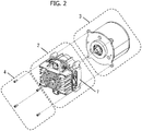
- Fig. 2 illustrates a constitution diagram in which a main body unit and a motor unit of the scroll-type fluid machine are separated from each other.
- the scroll-type fluid machine illustrated in Fig. 1 may be a scroll-type compressor which compresses specific gas or refrigerant such as air or nitrogen, or may be a scroll-type vacuum pump.
- the scroll-type fluid machine 1 includes a main body unit 2 and a motor unit 3 for driving the main body unit 2, and both of them are fastened by a fastening member 4.
- Fig. 3 illustrates an example of a cross-sectional view of a scroll-type fluid machine 1 in Fig. 1 as seen from the side.
- an internal structure of the main body unit 2 is constituted by a fixed scroll 5, an orbiting scroll 6 disposed to face the fixed scroll 5, and a main body casing 7 for covering the orbiting scroll 6 from an outer side in a radial direction.
- spiral wrap parts 5B and 6B are formed on the surfaces of the end plates 5A and 6A, respectively.
- a compression chamber 8 is formed by overlapping wrap parts 5B and 6B of the fixed scroll 5 and the orbiting scroll 6.
- the main body casing 7 has a tubular shape, and both ends thereof are open.
- the fixed scroll 5 is attached to an opening portion on one end side of the main body casing 7, and the motor unit 3 is attached to an opening portion 7A on the other end side.
- the orbiting scroll 6 is driven by the motor unit 3 and makes an orbiting motion.
- the compression chamber 8 defined between the wrap part 5B of the fixed scroll 5 and the orbiting scroll 6B by the orbiting motion of the orbiting scroll 6 is continuously contracted to compress and discharge the fluid.
- the scroll-type fluid machine 1 having only a pair of the fixed scroll 5 and the orbiting scroll 6 has been described as an example, but a configuration which includes the orbiting scroll 6 having the wrap part 6B on both sides of the end plate 6A and has the fixed scroll 5 on both sides thereof may be provided.
- the orbiting scroll 6 includes a boss portion 10A that accommodates a shaft 9 of the motor unit 3 on a rear side (a side opposite to a surface on which the wrap part 6B is formed) of the end plate 6A.
- the boss portion 10A may be formed on a back side (a surface opposite to the orbiting scroll 6) of a boss plate 10 by providing the boss plate 10 at a position separated from the back side of the end plate 6A, and may be directly formed on the back side of the end plate 6A of the orbiting scroll 6.
- a orbiting bearing 11 (11A, 11B, and 11C) which supports a centrifugal force generated by the orbiting motion of the orbiting scroll 6 and a gas load generated by compressing the air is formed in a boss portion 10A provided on the back side of the orbiting scroll 6.
- a plurality of rotation preventing mechanisms for preventing rotation motion of the orbiting scroll 6 is provided between the main body casing 7 and the orbiting scroll 6.
- the rotation preventing mechanism prevents the rotation motion of the orbiting scroll 6, and supports the gas load in an axial direction from the orbiting scroll 6.
- the rotation preventing mechanism includes an auxiliary crankshaft 13 in which two eccentric shafts are integrally formed in the axial direction, are held in the radial direction by a main casing side auxiliary crank bearing 12 and rotate following the orbiting scroll 6 to prevent rotation of the orbiting scroll 6, an orbiting scroll side auxiliary crank bearing 14 which supports the auxiliary crankshaft 13 and is accommodated in the orbiting scroll 6, and a main casing side auxiliary crank bearing 12 accommodated in the main body casing 7.
- a rotation preventing mechanism instead of the auxiliary crank mechanism described here, for example, a ball coupling mechanism, an Oldham coupling or the like may be used.
- the motor unit 3 includes a stator 15 and a rotor 16 that generate power, and a shaft 9 that integrates the rotor 16 by press fitting or the like and transmits the power to the outside.
- the stator 15 applies rotational force to the rotor 16
- the shaft 9 integrated with the rotor 16 rotates.
- the shaft 9 has an eccentric part 9A, the eccentric part 9A is accommodated in a boss portion 10A provided on the back side of the orbiting scroll 6 when assembling the main body unit 2 and the motor unit 3 and is attachably and detachably connected to the main body unit 2.
- the eccentric part 9A of the shaft 9 performs an eccentric motion with turning motion of the shaft 9.
- the motor unit 3 has a stator 15 and a motor casing 17 for accommodating the rotor 16.
- the motor casing 17 may be divided into a plurality of components.
- the motor casing 17 is fixed to the stator 15 and accommodates the stator 15 and the rotor 16.
- the shaft 9 is supported by an output side bearing 18 and a counter output side bearing 19.
- the output side bearing 18 and the counter output side bearing 19 are disposed coaxially so that the shaft 9 is not inclined with respect to the axis of the output side bearing 18 and the counter output side bearing 19. This suppresses vibrations generated by the inclination of the shaft 9 at the time of the operation of the scroll-type fluid machine 1, suppresses an unbalanced load on the orbiting bearing 11, and prevents a decrease in the service life of the orbiting bearing 11.
- the eccentric part 9A of the shaft 9 is provided in the main body unit 2, it is necessary to fasten the shaft 9 and the eccentric part 9A using a shaft fastening member such as a coupling. That is, the misalignment occurring between an orbiting center axis of the orbiting scroll 6 and the axial center of the shaft 9 can be mitigated and adjusted by the shaft fastening member.
- a shaft fastening member such as a coupling.
- the number of components increases, the number of processes increases, and an axial dimension length becomes longer. Therefore, it is conceivable to adopt a configuration in which the eccentric part 9A of the shaft 9 is provided in the motor unit 3.
- the positioning member 20 is a member for accurately positioning the main body unit 2 and the motor unit 3, and is made separate from the fastening member 4. By separating the positioning member 20 and the fastening member 4, deformation of the positioning part generated by the fastening member 4 at the time of fastening the main body unit 2 and the motor unit 3 and core misalignment caused thereby are prevented.
- the fastening member 4 has screw grooves on its surface, but the positioning member 20 does not have screw grooves on its surface.
- a positioning jig is required when assembling and reassembling at the time of maintenance.
- a positioning jig is required when positioning of the eccentric part 9A and the center of the orbiting scroll wrap part 6B, and positioning of the main body unit 2 and the motor unit 3 are performed at the same time, for example, a jig for restricting the turning of the eccentric part 9A and the orbiting scroll 6 is required.
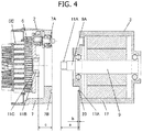
- Fig. 4 is a cross-sectional side view in a separated state of the main body unit 2 and the motor unit 3 of the scroll-type fluid machine 1 in this example.
- a protruding dimension of the shaft 9 from an entrance of a positioning hole 17A provided in the motor casing 17 is defined as a
- a length of the positioning member 20 protruding from the entrance of the positioning hole 17A is defined as b
- a distance from an entrance of a positioning hole 7B provided in the main body casing 7 to an end surface of the orbiting bearing roller 11B on an insertion side of the shaft 9 is defined as c.
- the positioning member 20 and the positioning hole 7B can be positioned in a state in which the relative position between the orbiting scroll 6 and the eccentric part 9A is determined, a jig is not necessary, the connection between the main body unit 2 and the motor unit 3 can be performed in the same process, and the assembling performance is improved.
- the orbiting bearing 11 is a roller bearing, but it may be a ball bearing or a sliding bearing.
- a distance from the entrance of the positioning hole 7B provided in the main body casing 7 to the ball bearing inner ring or the end surface of the sliding bearing on the side of the motor unit 3 is defined as c.
- a protruding part may be provided on the main body casing 7 or the motor casing 17.
- a protruding part instead of the positioning member, it is possible to reduce the number of components and to improve workability.
- a spigot may be provided in the main body casing 7 and the motor casing 17. This makes it possible to prevent deformation of the positioning member 20 due to the own weight of the main body unit 2 or the motor unit 3 being applied to the positioning member 20 when separating the main body unit 2 and the motor unit 3.
- the positioning member 20 may be a positioning pin. If it is a positioning pin, it can be exchanged when the surface of the positioning part is worn. Furthermore, workability is improved by making the positioning pin a tapered pin.
- the number of the positioning members 20 may be two or more, and a length h of the positioning member 20 may be different. In that case, a protruding length b of the positioning member 20 uses the length of the longest positioning member 20 in formulas (1), (2) and (3). If the length of the positioning member 20 is different, there is no need to simultaneously connect the plurality of positioning members 20, and workability is improved.
- the positioning member 20 may be fixed to the positioning hole 7B provided in the main body unit 2 or may be fixed to the positioning hole 17A provided in the motor unit 3.
- one or more positioning members 20 may be provided in the positioning hole 7B provided in the main body unit 2, and one or more positioning members 20 may be provided in the positioning hole 17A provided in the motor unit 3.
- the positioning member 20 may be a stepped pin having a large-diameter part and a small-diameter part shorter in the radial direction than the large-diameter part. Therefore, there is an effect in which it is possible to reduce the space of the positioning hole into which the positioning member 20 is inserted, and positioning in the axial direction can also be performed.
- the positioning hole 7B of the main body casing 7 is disposed on the outer side in the radial direction than the rotation preventing mechanism for preventing rotation of the orbiting scroll. This further improves the assembling performance.
- the present example is a scroll-type fluid machine which includes a main body unit having a main body casing, a fixed scroll and an orbiting scroll provided to face the fixed scroll to make an orbiting motion; and a motor unit having a drive shaft connected to the main body unit to drive the main body unit and a motor casing, wherein the drive shaft protrudes from the motor casing and is attached to a slewing bearing of the main body unit, the motor casing and the main body casing have positioning holes into which each of positioning members are inserted on respective facing mating surfaces, and a dimensional difference in an axial direction between an insertion port of the positioning hole on the main body casing side and an end surface of the slewing bearing on the motor casing side is configured to be smaller than a dimensional difference in the axial direction of a tip end on the main body unit side between the drive shaft and the positioning member.
- a scroll-type fluid machine which includes a main body unit having a main body casing, a fixed scroll and an orbiting scroll provided to face the fixed scroll to make an orbiting motion; and a motor unit having a drive shaft connected to the main body unit to drive the main body unit and a motor casing, wherein the drive shaft protrudes from the motor casing and is attached to a slewing bearing of the main body unit, the motor casing and the main body casing have positioning holes into which the positioning member is inserted on respective mating surfaces, and a dimensional difference in the axial direction between the end surface of the slewing bearing on the motor casing side and the insertion port of the positioning hole on the main body casing side is configured to be smaller than a difference between a protruding dimension of the drive shaft in the axial direction from an insertion port of the positioning hole on the motor casing side and a protruding dimension of the positioning member from the insertion port of the positioning hole on the motor casing side or on the main body casing side
- a method for assembling a fluid machine having a main body unit which expands or compresses a fluid and a motor unit which drives the main body unit, wherein after inserting the drive shaft of the motor unit into the main body unit, the positioning member is inserted into a positioning hole of the motor unit or the main body unit to perform positioning.
- Fig. 5 is a cross-sectional side view in a separated state of the main body unit and the motor unit of the scroll-type fluid machine in this example.
- the same constituent elements as those in Fig. 4 of the first example are denoted by same reference numerals, and the repeated thereof will not be provided.
- the orbiting bearing 11 (11A, 11B, and 11C) and the eccentric part 9A are attached to the main body unit 2 or the motor unit 3, to be movable on the circumference of the radius d around the orbiting center of the orbiting scroll 6 or the axial center of the shaft 9.
- the shaft insertion guide part 10B for guiding the shaft 9 to the orbiting bearing 11 on the side closer the motor unit 3 than the orbiting bearing 11 of the boss plate 10, it is possible to further improve the workability.
- the shaft insertion guide part 10B has an inner diameter equal to or larger than the inner diameter of the orbiting bearing roller 11B, and has a chamfer of a width e.
- the width e is set to formula (4) when the eccentricity of the eccentric part 9A is defined as d.
- the chamfer has the width e, but the surface of the shaft insertion guide part 10B may have a curved surface shape.
- the present invention is not limited to the examples described above, but includes various modified examples.
- the above-described examples have been described in detail in order to explain the present invention in an easy-to-understand manner, and are not necessarily limited to those having all the configurations described.
Landscapes
- Engineering & Computer Science (AREA)
- Mechanical Engineering (AREA)
- General Engineering & Computer Science (AREA)
- Applications Or Details Of Rotary Compressors (AREA)
- Rotary Pumps (AREA)
Abstract
Description
- The present invention relates to a scroll-type fluid machine and a method for assembling the same.
- As a background art of the present invention, there is
JP 2009-97358 A Patent Document 1 discloses "a hermetic type scroll compressor which includes a compression mechanism unit including a fixed scroll and an orbiting scroll in an hermetic case, a motor for applying a rotational driving force to the orbiting scroll via a drive shaft, an upper balancer disposed in a cylindrical orbiting space formed in a frame member on a rear side of the orbiting scroll and attached to the drive shaft, a middle balancer attached to the drive shaft or a rotary element of a rotor on an upper side of the motor, and a lower balancer attached to the drive shaft or the rotary element of the rotor on a lower side of the motor, in which a main bearing for supporting the drive shaft is mounted between the upper balancer and the middle balancer, a bearing fitting hole to which the main bearing is fitted is formed below the orbiting space of the frame member, an inner diameter of the bearing fitting hole is formed to be larger than an inner diameter of the orbiting space to coincide with an axial center of the orbiting space, and the bearing is configured to be attachable to the bearing fitting hole in a state in which the main bearing, the upper, middle and lower balancers, and the rotor of the motor are attached to the drive shaft". - Patent Document 1:
JP 2009-97358 A - The hermetic
type scroll compressor 1 ofPatent Document 1 is provided on aframe member 7 to which a bearing fitting hole 100 with a main bearing 43 fitted thereto is bolted to afixed scroll 17. Axial centers of acompression mechanism unit 9 and amotor 13 are determined by fitting between the bearing fitting hole 100 and the main bearing 43, but since the bearing fitting hole 100 is provided in thecompression mechanism unit 9, it is not easy to separate and connect thecompression mechanism unit 9 and themotor 13. - Therefore, if the bearing fitting hole 100 is provided in a motor frame 53, the
compression mechanism unit 9 and themotor 13 can be easily separated and connected. In this case, even in the scroll-type compressor 1 in which themotor 13 is built in, all of thecompression mechanism unit 9, themotor 13, and their connections can be performed at different factories and places. Further, if the main bearing is provided in the motor frame 53, regardless of whether themotor 13 is a built-in scroll-type compressor 1, thecompression mechanism unit 9 and themotor 13 can be operated as a single unit, and the operation can be checked. - However, if the bearing fitting hole 100 is provided in the motor frame 53, while aligning the axial center of the orbiting scroll freely rotatable on a certain orbiting radius with an axial center of a shaft eccentric part similarly freely rotatable on the same radius, apart from orbiting scroll, it is necessary to position the
compression mechanism unit 9 and themotor 13 with uniquely fixed positions, which deteriorates the assembling performance. - In view of the above problem, an object of the present invention is to provide a scroll-type compressor in which the main body unit and the motor unit can be separated and connected without being disassembled, while positioning of the eccentric shaft and the non-eccentric part can be performed easily in the same process and a method for manufacturing the same.
- In order to solve the above problem, the present invention provides, for example, a scroll-type fluid machine which includes a main body unit having a main body casing, a fixed scroll, and an orbiting scroll provided to face the fixed scroll to make an orbiting motion; and a motor unit having a drive shaft connected to the main body unit to drive the main body unit and a motor casing. The drive shaft protrudes from the motor casing and is attached to a slewing bearing of the main body unit. The motor casing and the main body casing have positioning holes into which a positioning member is inserted on respective mating surfaces. A dimensional difference in an axial direction between an insertion port of the positioning hole on the main body casing side and an end surface of the slewing bearing on the motor casing side is configured to be smaller than a dimensional difference in the axial direction of a tip end on the main body unit side between the drive shaft and the positioning member.
- According to the present invention, it is possible to provide a scroll-type compressor in which the main body unit and the motor unit can be separated and connected without being disassembled, while positioning of the eccentric shaft and the non-eccentric part can be performed easily in the same process and a method for manufacturing the same.
-
-
Fig. 1 is an overall view of a scroll-type fluid machine according to a first example. -
Fig. 2 is a separated view of a main body unit and a motor unit of the scroll-type fluid machine according to the first example. -
Fig. 3 is a side cross-sectional view of the scroll-type fluid machine according to the first example. -
Fig. 4 is a side cross-sectional view in a separated state of the main body unit and the motor unit of the scroll-type fluid machine according to the first example. -
Fig. 5 is a side cross-sectional view in a separated state of the main body unit and the motor unit of the scroll-type fluid machine according to a second example. - A first example of the present invention will be described below with reference to the drawings.
-
Fig. 1 illustrates an overall schematic view of a scroll-type fluid machine in this example, andFig. 2 illustrates a constitution diagram in which a main body unit and a motor unit of the scroll-type fluid machine are separated from each other. - The scroll-type fluid machine illustrated in
Fig. 1 may be a scroll-type compressor which compresses specific gas or refrigerant such as air or nitrogen, or may be a scroll-type vacuum pump. The scroll-type fluid machine 1 includes amain body unit 2 and amotor unit 3 for driving themain body unit 2, and both of them are fastened by afastening member 4. -
Fig. 3 illustrates an example of a cross-sectional view of a scroll-type fluid machine 1 inFig. 1 as seen from the side. As illustrated inFig. 3 , an internal structure of themain body unit 2 is constituted by afixed scroll 5, anorbiting scroll 6 disposed to face thefixed scroll 5, and amain body casing 7 for covering the orbitingscroll 6 from an outer side in a radial direction. In thefixed scroll 5 and the orbitingscroll 6,spiral wrap parts end plates compression chamber 8 is formed by overlappingwrap parts fixed scroll 5 and the orbitingscroll 6. Themain body casing 7 has a tubular shape, and both ends thereof are open. Thefixed scroll 5 is attached to an opening portion on one end side of themain body casing 7, and themotor unit 3 is attached to anopening portion 7A on the other end side. The orbitingscroll 6 is driven by themotor unit 3 and makes an orbiting motion. In themain body unit 2, thecompression chamber 8 defined between thewrap part 5B of thefixed scroll 5 and the orbitingscroll 6B by the orbiting motion of the orbitingscroll 6 is continuously contracted to compress and discharge the fluid. Incidentally, in the present example, the scroll-type fluid machine 1 having only a pair of thefixed scroll 5 and the orbitingscroll 6 has been described as an example, but a configuration which includes theorbiting scroll 6 having thewrap part 6B on both sides of theend plate 6A and has thefixed scroll 5 on both sides thereof may be provided. The orbitingscroll 6 includes aboss portion 10A that accommodates ashaft 9 of themotor unit 3 on a rear side (a side opposite to a surface on which thewrap part 6B is formed) of theend plate 6A. - As illustrated in
Fig. 3 , theboss portion 10A may be formed on a back side (a surface opposite to the orbiting scroll 6) of aboss plate 10 by providing theboss plate 10 at a position separated from the back side of theend plate 6A, and may be directly formed on the back side of theend plate 6A of theorbiting scroll 6. - A orbiting bearing 11 (11A, 11B, and 11C) which supports a centrifugal force generated by the orbiting motion of the orbiting
scroll 6 and a gas load generated by compressing the air is formed in aboss portion 10A provided on the back side of the orbitingscroll 6. - A plurality of rotation preventing mechanisms for preventing rotation motion of the orbiting
scroll 6 is provided between themain body casing 7 and the orbitingscroll 6. The rotation preventing mechanism prevents the rotation motion of the orbitingscroll 6, and supports the gas load in an axial direction from the orbitingscroll 6. The rotation preventing mechanism includes anauxiliary crankshaft 13 in which two eccentric shafts are integrally formed in the axial direction, are held in the radial direction by a main casing side auxiliary crank bearing 12 and rotate following the orbitingscroll 6 to prevent rotation of the orbitingscroll 6, an orbiting scroll sideauxiliary crank bearing 14 which supports theauxiliary crankshaft 13 and is accommodated in the orbitingscroll 6, and a main casing side auxiliary crank bearing 12 accommodated in themain body casing 7. Incidentally, as a rotation preventing mechanism, instead of the auxiliary crank mechanism described here, for example, a ball coupling mechanism, an Oldham coupling or the like may be used. - As illustrated in
Fig. 3 , themotor unit 3 includes astator 15 and arotor 16 that generate power, and ashaft 9 that integrates therotor 16 by press fitting or the like and transmits the power to the outside. As thestator 15 applies rotational force to therotor 16, theshaft 9 integrated with therotor 16 rotates. Theshaft 9 has aneccentric part 9A, theeccentric part 9A is accommodated in aboss portion 10A provided on the back side of theorbiting scroll 6 when assembling themain body unit 2 and themotor unit 3 and is attachably and detachably connected to themain body unit 2. Theeccentric part 9A of theshaft 9 performs an eccentric motion with turning motion of theshaft 9. Therefore, as theshaft 9 turns, theorbiting scroll 6 connected to theeccentric part 9A makes an orbiting motion. Further, themotor unit 3 has astator 15 and amotor casing 17 for accommodating therotor 16. Themotor casing 17 may be divided into a plurality of components. Themotor casing 17 is fixed to thestator 15 and accommodates thestator 15 and therotor 16. Theshaft 9 is supported by an output side bearing 18 and a counter output side bearing 19. The output side bearing 18 and the counter output side bearing 19 are disposed coaxially so that theshaft 9 is not inclined with respect to the axis of the output side bearing 18 and the counter output side bearing 19. This suppresses vibrations generated by the inclination of theshaft 9 at the time of the operation of the scroll-type fluid machine 1, suppresses an unbalanced load on the orbitingbearing 11, and prevents a decrease in the service life of the orbiting bearing 11. - Here, when the
eccentric part 9A of theshaft 9 is provided in themain body unit 2, it is necessary to fasten theshaft 9 and theeccentric part 9A using a shaft fastening member such as a coupling. That is, the misalignment occurring between an orbiting center axis of the orbitingscroll 6 and the axial center of theshaft 9 can be mitigated and adjusted by the shaft fastening member. However, in that case, there is a problem that the number of components increases, the number of processes increases, and an axial dimension length becomes longer. Therefore, it is conceivable to adopt a configuration in which theeccentric part 9A of theshaft 9 is provided in themotor unit 3. However, with this configuration, it is necessary to position themain body unit 2 and themotor unit 3, while aligning the axial center between the orbitingbearing 11 and theeccentric part 9A of theshaft 9, which causes a problem of deteriorating the assembling performance. It is necessary to solve this problem. - The positioning
member 20 is a member for accurately positioning themain body unit 2 and themotor unit 3, and is made separate from thefastening member 4. By separating the positioningmember 20 and thefastening member 4, deformation of the positioning part generated by thefastening member 4 at the time of fastening themain body unit 2 and themotor unit 3 and core misalignment caused thereby are prevented. Thefastening member 4 has screw grooves on its surface, but the positioningmember 20 does not have screw grooves on its surface. - Next, a positional relation between the positioning
member 20 and theshaft 9 will be described. In the scroll-type fluid machine 1 having theeccentric part 9A of theshaft 9 provided in themotor unit 3, when connecting themain body unit 2 and themotor unit 3, it is necessary to align the positions of the centers of theeccentric part 9A and the orbiting scroll wrappart 6B, and align the positions of themain body unit 2 and themotor unit 3. - When positioning of the
main body unit 2 and themotor unit 3 is made loose, a positioning jig is required when assembling and reassembling at the time of maintenance. When positioning of theeccentric part 9A and the center of the orbiting scroll wrappart 6B, and positioning of themain body unit 2 and themotor unit 3 are performed at the same time, for example, a jig for restricting the turning of theeccentric part 9A and theorbiting scroll 6 is required. - When positioning the
main body unit 2 and themotor unit 3 is performed earlier than positioning of theeccentric part 9A and the center of the orbiting scroll wrappart 6B, a dimension of the positioningmember 20 in the axial direction of theshaft 9 direction becomes longer, and it is difficult to visually observe a orbiting bearingouter ring 11C in the orbitingbearing 11. Therefore, there are problems in which it is necessary to position the orbiting bearingouter ring 11C before connecting the positioningmember 20 and it is difficult to adjust the position of the orbiting bearingouter ring 11C after connecting the positioningmember 20. In addition, since a contact area between the positioningmember 20 and thepositioning hole 7B increases, the friction at the positioning part when connecting themain body unit 2 and themotor unit 3 increases, and the workability is deteriorated. - Therefore, by adopting a positioning structure illustrated in
Fig. 4 , workability can be improved.Fig. 4 is a cross-sectional side view in a separated state of themain body unit 2 and themotor unit 3 of the scroll-type fluid machine 1 in this example. InFig. 4 , a protruding dimension of theshaft 9 from an entrance of apositioning hole 17A provided in themotor casing 17 is defined as a, a length of the positioningmember 20 protruding from the entrance of thepositioning hole 17A is defined as b, and a distance from an entrance of apositioning hole 7B provided in themain body casing 7 to an end surface of theorbiting bearing roller 11B on an insertion side of theshaft 9 is defined as c. - When the shaft insertion side end surface of the
orbiting bearing roller 11B is closer to the motor side than the entrance of the main bodycasing positioning hole 7B, a relation of formula (1) or (2) is established. Also, when the shaft insertion side end surface of theorbiting bearing roller 11B is on a side opposite to the motor from the entrance of the main bodycasing positioning hole 7B, a relation of formula (3) is established.


- When positioning the
eccentric part 9A and the center of the orbiting scroll wrappart 6B, as a substantial work, positioning of the orbitingbearing 11 and the shafteccentric part 9A is performed. If it is constituted by the dimensions determined by the formulas (1), (2) and (3), when themain body unit 2 and themotor unit 3 are connected to each other, a tip end of theeccentric part 9A is first inserted into the orbitingbearing 11, and then positioningmember 20 is connected to thepositioning hole 7B. In a state in which the tip end of theeccentric part 9A is inserted into the orbitingbearing 11, themain body unit 2 can perform an orbiting motion about the axial center of theshaft 9 of themotor unit 3. Therefore, the positioningmember 20 and thepositioning hole 7B can be positioned in a state in which the relative position between the orbitingscroll 6 and theeccentric part 9A is determined, a jig is not necessary, the connection between themain body unit 2 and themotor unit 3 can be performed in the same process, and the assembling performance is improved. - Incidentally, in the drawing of this example, the orbiting
bearing 11 is a roller bearing, but it may be a ball bearing or a sliding bearing. In the case of the ball bearing or the sliding bearing, a distance from the entrance of thepositioning hole 7B provided in themain body casing 7 to the ball bearing inner ring or the end surface of the sliding bearing on the side of themotor unit 3 is defined as c. - Further, instead of using the
positioning member 20, a protruding part may be provided on themain body casing 7 or themotor casing 17. By using a protruding part instead of the positioning member, it is possible to reduce the number of components and to improve workability. - Further, instead of using the
positioning member 20, a spigot may be provided in themain body casing 7 and themotor casing 17. This makes it possible to prevent deformation of the positioningmember 20 due to the own weight of themain body unit 2 or themotor unit 3 being applied to the positioningmember 20 when separating themain body unit 2 and themotor unit 3. - Further, the positioning
member 20 may be a positioning pin. If it is a positioning pin, it can be exchanged when the surface of the positioning part is worn. Furthermore, workability is improved by making the positioning pin a tapered pin. - The number of the
positioning members 20 may be two or more, and a length h of the positioningmember 20 may be different. In that case, a protruding length b of the positioningmember 20 uses the length of thelongest positioning member 20 in formulas (1), (2) and (3). If the length of the positioningmember 20 is different, there is no need to simultaneously connect the plurality ofpositioning members 20, and workability is improved. - Further, the positioning
member 20 may be fixed to thepositioning hole 7B provided in themain body unit 2 or may be fixed to thepositioning hole 17A provided in themotor unit 3. In a case where the plurality ofpositioning members 20 is provided, one ormore positioning members 20 may be provided in thepositioning hole 7B provided in themain body unit 2, and one ormore positioning members 20 may be provided in thepositioning hole 17A provided in themotor unit 3. - Further, the positioning
member 20 may be a stepped pin having a large-diameter part and a small-diameter part shorter in the radial direction than the large-diameter part. Therefore, there is an effect in which it is possible to reduce the space of the positioning hole into which thepositioning member 20 is inserted, and positioning in the axial direction can also be performed. - Further, the
positioning hole 7B of themain body casing 7 is disposed on the outer side in the radial direction than the rotation preventing mechanism for preventing rotation of the orbiting scroll. This further improves the assembling performance. - In this way, the present example is a scroll-type fluid machine which includes a main body unit having a main body casing, a fixed scroll and an orbiting scroll provided to face the fixed scroll to make an orbiting motion; and a motor unit having a drive shaft connected to the main body unit to drive the main body unit and a motor casing, wherein the drive shaft protrudes from the motor casing and is attached to a slewing bearing of the main body unit, the motor casing and the main body casing have positioning holes into which each of positioning members are inserted on respective facing mating surfaces, and a dimensional difference in an axial direction between an insertion port of the positioning hole on the main body casing side and an end surface of the slewing bearing on the motor casing side is configured to be smaller than a dimensional difference in the axial direction of a tip end on the main body unit side between the drive shaft and the positioning member.
- Moreover, provided is a scroll-type fluid machine which includes a main body unit having a main body casing, a fixed scroll and an orbiting scroll provided to face the fixed scroll to make an orbiting motion; and a motor unit having a drive shaft connected to the main body unit to drive the main body unit and a motor casing, wherein the drive shaft protrudes from the motor casing and is attached to a slewing bearing of the main body unit, the motor casing and the main body casing have positioning holes into which the positioning member is inserted on respective mating surfaces, and a dimensional difference in the axial direction between the end surface of the slewing bearing on the motor casing side and the insertion port of the positioning hole on the main body casing side is configured to be smaller than a difference between a protruding dimension of the drive shaft in the axial direction from an insertion port of the positioning hole on the motor casing side and a protruding dimension of the positioning member from the insertion port of the positioning hole on the motor casing side or on the main body casing side.
- Further, a method for assembling a fluid machine having a main body unit which expands or compresses a fluid and a motor unit which drives the main body unit, wherein after inserting the drive shaft of the motor unit into the main body unit, the positioning member is inserted into a positioning hole of the motor unit or the main body unit to perform positioning.
- Therefore, it is possible to provide a scroll-type fluid machine and a method for assembling the same capable of performing the positioning of the eccentric shaft and the non-eccentric part easily and in the same process, while being capable of separating and connecting the main body unit and the motor unit in a non-disassembled state.
-
Fig. 5 is a cross-sectional side view in a separated state of the main body unit and the motor unit of the scroll-type fluid machine in this example. The same constituent elements as those inFig. 4 of the first example are denoted by same reference numerals, and the repeated thereof will not be provided. The orbiting bearing 11 (11A, 11B, and 11C) and theeccentric part 9A are attached to themain body unit 2 or themotor unit 3, to be movable on the circumference of the radius d around the orbiting center of theorbiting scroll 6 or the axial center of theshaft 9. In the first example, it is necessary to first insert the leading end of the shafteccentric part 9A into the orbitingbearing 11, and it is necessary to align the positions of the orbitingbearing 11 and theeccentric part 9A movable on the circumference of the radius d around the axial center of theshaft 9. Therefore, by providing the shaft insertion guide part 10B for guiding theshaft 9 to the orbiting bearing 11 on the side closer themotor unit 3 than the orbiting bearing 11 of theboss plate 10, it is possible to further improve the workability. The shaft insertion guide part 10B has an inner diameter equal to or larger than the inner diameter of theorbiting bearing roller 11B, and has a chamfer of a width e. The width e is set to formula (4) when the eccentricity of theeccentric part 9A is defined as d.
main body unit 2 and the axial center of themotor unit 3 are roughly aligned and connected, the positions of theeccentric part 9A and the orbiting bearing 11 are aligned with each other. - Incidentally, in
Fig. 5 , the chamfer has the width e, but the surface of the shaft insertion guide part 10B may have a curved surface shape. - Although the examples have been described above, the present invention is not limited to the examples described above, but includes various modified examples. For example, the above-described examples have been described in detail in order to explain the present invention in an easy-to-understand manner, and are not necessarily limited to those having all the configurations described. Further, it is also possible to add the configuration of another example to the configuration of one example. Further, it is possible to add, delete, and replace other configurations for some of each example.
-
- 1
- Scroll-type fluid machine
- 2
- Main body unit
- 3
- Motor unit
- 4
- Fastening member
- 5
- Fixed scroll
- 5A
- Fixed scroll end plate
- 5B
- Fixed scroll wrap part
- 6
- Orbiting scroll
- 6A
- Orbiting scroll end plate
- 6B
- Orbiting scroll wrap part
- 7
- Main body casing
- 7A
- Main body casing opening portion
- 7B
- Main body unit side positioning hole
- 8
- Compression chamber
- 9
- Shaft
- 9A
- Eccentric part
- 10
- Boss plate
- 10A
- Boss portion
- 10B
- Shaft insertion guide part
- 11
- Orbiting bearing
- 11A
- Orbiting bearing inner ring
- 11B
- Orbiting bearing roller
- 11C
- Orbiting bearing outer ring
- 12
- Main body casing-side auxiliary crank bearing
- 13
- Auxiliary crankshaft
- 14
- Orbiting scroll side auxiliary crank bearing
- 15
- Stator
- 16
- Rotor
- 17
- Motor casing
- 17A
- Motor casing side positioning hole
- 18
- Output-side bearing
- 19
- Counter output side bearing
- 20
- Positioning member
Claims (17)
- A scroll-type fluid machine comprising: a main body unit having a main body casing, a fixed scroll, and an orbiting scroll provided to face the fixed scroll to make an orbiting motion; and a motor unit having a drive shaft connected to the main body unit to drive the main body unit and a motor casing,
wherein the drive shaft protrudes from the motor casing and is attached to a slewing bearing of the main body unit,
the motor casing and the main body casing have positioning holes into which a positioning member is inserted on respective mating surfaces, and
a dimensional difference in an axial direction between an insertion port of the positioning hole on the main body casing side and an end surface of the slewing bearing on the motor casing side is configured to be smaller than a dimensional difference in the axial direction of a tip end on the main body unit side between the drive shaft and the positioning member. - The scroll-type fluid machine according to claim 1, wherein the drive shaft is attached to the slewing bearing via an eccentric part, and the eccentric part is provided on the motor unit side.
- The scroll-type fluid machine according to claim 1, wherein a plurality of positioning members and a plurality of positioning holes are provided in each of the motor casing and the main casing.
- The scroll-type fluid machine according to claim 3, wherein a dimensional difference in the axial direction between an end surface of the slewing bearing on the motor casing side and the insertion port of the positioning hole on the main body casing side is smaller than a dimensional difference in the axial direction on the tip end of the main unit side between the drive shaft and the positioning member protruding most from the positioning hole.
- The scroll-type fluid machine according to claim 1, wherein the positioning member is a stepped pin having a large-diameter part and a small-diameter part having a radial length shorter than the large-diameter part.
- The scroll-type fluid machine according to claim 1, wherein the positioning hole of the main body casing is disposed on an outer side in the radial direction than a rotation preventing mechanism which prevents rotation of the orbiting scroll.
- The scroll-type fluid machine according to claim 1, wherein the positioning member does not have a screw groove.
- The scroll-type fluid machine according to claim 1, wherein a fastening member which fastens the main body unit and the motor unit is provided, and the positioning member is a separate body from the fastening member.
- A scroll-type fluid machine comprising:a main body unit having a main body casing, a fixed scroll, and an orbiting scroll provided to face the fixed scroll to make an orbiting motion; anda motor unit having a drive shaft connected to the main body unit to drive the main body unit and a motor casing,wherein the drive shaft protrudes from the motor casing and is attached to a slewing bearing of the main body unit, the motor casing and the main body casing have positioning holes into which a positioning member is inserted on respective mating surfaces, and a dimensional difference in an axial direction between an end surface of the slewing bearing on the motor casing side and an insertion port of the positioning hole on the main body casing side is smaller than a difference between a protruding dimension of the drive shaft in the axial direction from the insertion port of the positioning hole on the motor casing side and a protruding dimension of the positioning member from the insertion port of the positioning hole on the motor casing side or on the main body casing side.
- The scroll-type fluid machine according to claim 9, wherein the drive shaft is attached to the slewing bearing via an eccentric part, and the eccentric part is provided on the motor unit side.
- The scroll-type fluid machine according to claim 9, wherein a plurality of positioning members and a plurality of positioning holes are provided in each of the motor casing and the main casing.
- The scroll-type fluid machine according to claim 11, wherein a dimensional difference in the axial direction between an end surface of the slewing bearing on the motor casing side and the insertion hole of the positioning hole on the main body casing side is smaller than a difference between a protruding dimension of the drive shaft in the axial direction from the insertion port of the positioning hole on the motor casing side and a protruding dimension of the positioning member protruding most from the insertion port of the positioning hole on the motor casing side or on the main body casing side.
- The scroll-type fluid machine according to claim 9, wherein the positioning member is a stepped pin having a large-diameter part and a small-diameter part having a radial length shorter than the large-diameter part.
- The scroll-type fluid machine according to claim 9, wherein the positioning hole of the main body casing is disposed on an outer side in the radial direction than a rotation preventing mechanism which prevents rotation of the orbiting scroll.
- The scroll-type fluid machine according to claim 9, wherein the positioning member does not have a screw groove.
- The scroll-type fluid machine according to claim 9, wherein a fastening member which fastens the main body unit and the motor unit is provided, and the positioning member is a separate body from the fastening member.
- A method for assembling a fluid machine having a main body unit which expands or compresses a fluid, and a motor unit which drives the main body unit,
wherein after inserting a drive shaft of the motor unit into the main body unit, a positioning member is inserted into a positioning hole of the motor unit or the main body unit to perform positioning.
Applications Claiming Priority (1)
| Application Number | Priority Date | Filing Date | Title |
|---|---|---|---|
| PCT/JP2016/072274 WO2018020651A1 (en) | 2016-07-29 | 2016-07-29 | Scroll-type fluid machine and method for assembling same |
Publications (3)
| Publication Number | Publication Date |
|---|---|
| EP3492743A1 true EP3492743A1 (en) | 2019-06-05 |
| EP3492743A4 EP3492743A4 (en) | 2020-01-08 |
| EP3492743B1 EP3492743B1 (en) | 2024-10-16 |
Family
ID=61015938
Family Applications (1)
| Application Number | Title | Priority Date | Filing Date |
|---|---|---|---|
| EP16910554.1A Active EP3492743B1 (en) | 2016-07-29 | 2016-07-29 | Scroll-type fluid machine and method for assembling same |
Country Status (6)
| Country | Link |
|---|---|
| US (1) | US11015597B2 (en) |
| EP (1) | EP3492743B1 (en) |
| JP (1) | JP6734378B2 (en) |
| KR (1) | KR102023445B1 (en) |
| CN (1) | CN108700067B (en) |
| WO (1) | WO2018020651A1 (en) |
Cited By (1)
| Publication number | Priority date | Publication date | Assignee | Title |
|---|---|---|---|---|
| EP3495663A4 (en) * | 2016-08-03 | 2020-01-22 | Hitachi Industrial Equipment Systems Co., Ltd. | VOLUTE TYPE FLUID MACHINE |
Families Citing this family (2)
| Publication number | Priority date | Publication date | Assignee | Title |
|---|---|---|---|---|
| CN113250956B (en) * | 2021-07-05 | 2021-10-26 | 和氏工业技术股份有限公司 | Compressor assembly process |
| CN120958238A (en) * | 2023-07-06 | 2025-11-14 | 株式会社日立产机系统 | Maintenance methods for vortex fluid machinery and vortex fluid machinery |
Family Cites Families (13)
| Publication number | Priority date | Publication date | Assignee | Title |
|---|---|---|---|---|
| US5088906A (en) * | 1991-02-04 | 1992-02-18 | Tecumseh Products Company | Axially floating scroll member assembly |
| US5106279A (en) * | 1991-02-04 | 1992-04-21 | Tecumseh Products Company | Orbiting scroll member assembly |
| JP4594265B2 (en) | 2006-03-31 | 2010-12-08 | 株式会社日立製作所 | Scroll type fluid machine |
| JP5114709B2 (en) | 2007-10-12 | 2013-01-09 | 株式会社前川製作所 | Hermetic scroll compressor and its assembly method |
| JP2010043608A (en) * | 2008-08-13 | 2010-02-25 | Hitachi Ltd | Scroll fluid machine |
| KR101090569B1 (en) * | 2009-05-06 | 2011-12-08 | 한라공조주식회사 | Assembling method of swash plate and rotating shaft for compressor |
| JP5594196B2 (en) * | 2011-03-14 | 2014-09-24 | 株式会社豊田自動織機 | Scroll compressor for vehicles |
| US9057269B2 (en) | 2012-03-23 | 2015-06-16 | Bitzer Kuehlmaschinenbau Gmbh | Piloted scroll compressor |
| JP2014190245A (en) * | 2013-03-27 | 2014-10-06 | Keihin Corp | Scroll-type compressor |
| US8961160B2 (en) * | 2013-03-29 | 2015-02-24 | Agilent Technologies, Inc. | Scroll pump having separable orbiting plate scroll and method of replacing tip seal |
| JP6130763B2 (en) * | 2013-09-26 | 2017-05-17 | 株式会社日立産機システム | Scroll type fluid machine and its assembly method |
| JP6153836B2 (en) * | 2013-09-30 | 2017-06-28 | 株式会社日立産機システム | Scroll type fluid machine |
| CN204003475U (en) * | 2014-08-27 | 2014-12-10 | 李廷政 | Scroll compressor and scroll vacuum pump main shaft automatic compensator |
-
2016
- 2016-07-29 WO PCT/JP2016/072274 patent/WO2018020651A1/en not_active Ceased
- 2016-07-29 EP EP16910554.1A patent/EP3492743B1/en active Active
- 2016-07-29 CN CN201680082554.8A patent/CN108700067B/en active Active
- 2016-07-29 JP JP2018530293A patent/JP6734378B2/en active Active
- 2016-07-29 KR KR1020187024289A patent/KR102023445B1/en active Active
- 2016-07-29 US US16/086,829 patent/US11015597B2/en active Active
Cited By (2)
| Publication number | Priority date | Publication date | Assignee | Title |
|---|---|---|---|---|
| EP3495663A4 (en) * | 2016-08-03 | 2020-01-22 | Hitachi Industrial Equipment Systems Co., Ltd. | VOLUTE TYPE FLUID MACHINE |
| US10995752B2 (en) | 2016-08-03 | 2021-05-04 | Hitachi Industrial Equipment Systems Co., Ltd. | Scroll-type fluid machine |
Also Published As
| Publication number | Publication date |
|---|---|
| KR20180105200A (en) | 2018-09-27 |
| CN108700067B (en) | 2020-05-12 |
| WO2018020651A1 (en) | 2018-02-01 |
| EP3492743B1 (en) | 2024-10-16 |
| CN108700067A (en) | 2018-10-23 |
| EP3492743A4 (en) | 2020-01-08 |
| KR102023445B1 (en) | 2019-09-20 |
| JP6734378B2 (en) | 2020-08-05 |
| US11015597B2 (en) | 2021-05-25 |
| US20190101115A1 (en) | 2019-04-04 |
| JPWO2018020651A1 (en) | 2019-01-17 |
Similar Documents
| Publication | Publication Date | Title |
|---|---|---|
| US8556605B2 (en) | Scroll compressor having a rotation inhibitor | |
| JPH05118292A (en) | Compressor | |
| EP3492743B1 (en) | Scroll-type fluid machine and method for assembling same | |
| US20160123326A1 (en) | Scroll compressor | |
| CN116097001B (en) | Compressor and method for manufacturing compressor | |
| US7445437B1 (en) | Scroll type fluid machine having a first scroll wrap unit with a scroll member and a scroll receiving member, and a second scroll wrap unit engaged with the first scroll wrap unit | |
| CN212028054U (en) | Electric compressor | |
| EP3534005B1 (en) | Scroll compressor and method for producing same | |
| KR20180094056A (en) | Scroll compressor | |
| EP1947292B1 (en) | Fluid machine with crankshaft | |
| JP6918864B2 (en) | Scroll type fluid machine and its maintenance method, assembly method | |
| JP4303095B2 (en) | Scroll type fluid machine | |
| WO2025009142A1 (en) | Maintenance method for scroll fluid machine, and scroll fluid machine | |
| JPH1061569A (en) | Scroll compressor | |
| JP2003254244A (en) | Electric compressor | |
| KR101161463B1 (en) | Scroll compressor having frame united stator and manufacturing method thereof | |
| WO2008066104A1 (en) | Scroll fluid machine |
Legal Events
| Date | Code | Title | Description |
|---|---|---|---|
| STAA | Information on the status of an ep patent application or granted ep patent |
Free format text: STATUS: THE INTERNATIONAL PUBLICATION HAS BEEN MADE |
|
| PUAI | Public reference made under article 153(3) epc to a published international application that has entered the european phase |
Free format text: ORIGINAL CODE: 0009012 |
|
| STAA | Information on the status of an ep patent application or granted ep patent |
Free format text: STATUS: REQUEST FOR EXAMINATION WAS MADE |
|
| 17P | Request for examination filed |
Effective date: 20190228 |
|
| AK | Designated contracting states |
Kind code of ref document: A1 Designated state(s): AL AT BE BG CH CY CZ DE DK EE ES FI FR GB GR HR HU IE IS IT LI LT LU LV MC MK MT NL NO PL PT RO RS SE SI SK SM TR |
|
| AX | Request for extension of the european patent |
Extension state: BA ME |
|
| DAV | Request for validation of the european patent (deleted) | ||
| DAX | Request for extension of the european patent (deleted) | ||
| A4 | Supplementary search report drawn up and despatched |
Effective date: 20191206 |
|
| RIC1 | Information provided on ipc code assigned before grant |
Ipc: F04C 29/00 20060101ALI20191202BHEP Ipc: F01C 21/10 20060101ALI20191202BHEP Ipc: F01C 21/00 20060101ALI20191202BHEP Ipc: F04C 18/02 20060101AFI20191202BHEP |
|
| STAA | Information on the status of an ep patent application or granted ep patent |
Free format text: STATUS: EXAMINATION IS IN PROGRESS |
|
| 17Q | First examination report despatched |
Effective date: 20220610 |
|
| GRAP | Despatch of communication of intention to grant a patent |
Free format text: ORIGINAL CODE: EPIDOSNIGR1 |
|
| STAA | Information on the status of an ep patent application or granted ep patent |
Free format text: STATUS: GRANT OF PATENT IS INTENDED |
|
| INTG | Intention to grant announced |
Effective date: 20240522 |
|
| GRAS | Grant fee paid |
Free format text: ORIGINAL CODE: EPIDOSNIGR3 |
|
| GRAA | (expected) grant |
Free format text: ORIGINAL CODE: 0009210 |
|
| STAA | Information on the status of an ep patent application or granted ep patent |
Free format text: STATUS: THE PATENT HAS BEEN GRANTED |
|
| AK | Designated contracting states |
Kind code of ref document: B1 Designated state(s): AL AT BE BG CH CY CZ DE DK EE ES FI FR GB GR HR HU IE IS IT LI LT LU LV MC MK MT NL NO PL PT RO RS SE SI SK SM TR |
|
| REG | Reference to a national code |
Ref country code: GB Ref legal event code: FG4D |
|
| REG | Reference to a national code |
Ref country code: CH Ref legal event code: EP Ref country code: DE Ref legal event code: R096 Ref document number: 602016089902 Country of ref document: DE |
|
| REG | Reference to a national code |
Ref country code: IE Ref legal event code: FG4D |
|
| REG | Reference to a national code |
Ref country code: LT Ref legal event code: MG9D |
|
| REG | Reference to a national code |
Ref country code: NL Ref legal event code: MP Effective date: 20241016 |
|
| REG | Reference to a national code |
Ref country code: AT Ref legal event code: MK05 Ref document number: 1733106 Country of ref document: AT Kind code of ref document: T Effective date: 20241016 |
|
| PG25 | Lapsed in a contracting state [announced via postgrant information from national office to epo] |
Ref country code: NL Free format text: LAPSE BECAUSE OF FAILURE TO SUBMIT A TRANSLATION OF THE DESCRIPTION OR TO PAY THE FEE WITHIN THE PRESCRIBED TIME-LIMIT Effective date: 20241016 |
|
| PG25 | Lapsed in a contracting state [announced via postgrant information from national office to epo] |
Ref country code: NL Free format text: LAPSE BECAUSE OF FAILURE TO SUBMIT A TRANSLATION OF THE DESCRIPTION OR TO PAY THE FEE WITHIN THE PRESCRIBED TIME-LIMIT Effective date: 20241016 |
|
| PG25 | Lapsed in a contracting state [announced via postgrant information from national office to epo] |
Ref country code: IS Free format text: LAPSE BECAUSE OF FAILURE TO SUBMIT A TRANSLATION OF THE DESCRIPTION OR TO PAY THE FEE WITHIN THE PRESCRIBED TIME-LIMIT Effective date: 20250216 Ref country code: HR Free format text: LAPSE BECAUSE OF FAILURE TO SUBMIT A TRANSLATION OF THE DESCRIPTION OR TO PAY THE FEE WITHIN THE PRESCRIBED TIME-LIMIT Effective date: 20241016 Ref country code: PT Free format text: LAPSE BECAUSE OF FAILURE TO SUBMIT A TRANSLATION OF THE DESCRIPTION OR TO PAY THE FEE WITHIN THE PRESCRIBED TIME-LIMIT Effective date: 20250217 |
|
| PG25 | Lapsed in a contracting state [announced via postgrant information from national office to epo] |
Ref country code: FI Free format text: LAPSE BECAUSE OF FAILURE TO SUBMIT A TRANSLATION OF THE DESCRIPTION OR TO PAY THE FEE WITHIN THE PRESCRIBED TIME-LIMIT Effective date: 20241016 |
|
| PG25 | Lapsed in a contracting state [announced via postgrant information from national office to epo] |
Ref country code: BG Free format text: LAPSE BECAUSE OF FAILURE TO SUBMIT A TRANSLATION OF THE DESCRIPTION OR TO PAY THE FEE WITHIN THE PRESCRIBED TIME-LIMIT Effective date: 20241016 |
|
| PG25 | Lapsed in a contracting state [announced via postgrant information from national office to epo] |
Ref country code: ES Free format text: LAPSE BECAUSE OF FAILURE TO SUBMIT A TRANSLATION OF THE DESCRIPTION OR TO PAY THE FEE WITHIN THE PRESCRIBED TIME-LIMIT Effective date: 20241016 |
|
| PG25 | Lapsed in a contracting state [announced via postgrant information from national office to epo] |
Ref country code: NO Free format text: LAPSE BECAUSE OF FAILURE TO SUBMIT A TRANSLATION OF THE DESCRIPTION OR TO PAY THE FEE WITHIN THE PRESCRIBED TIME-LIMIT Effective date: 20250116 |
|
| PG25 | Lapsed in a contracting state [announced via postgrant information from national office to epo] |
Ref country code: GR Free format text: LAPSE BECAUSE OF FAILURE TO SUBMIT A TRANSLATION OF THE DESCRIPTION OR TO PAY THE FEE WITHIN THE PRESCRIBED TIME-LIMIT Effective date: 20250117 Ref country code: AT Free format text: LAPSE BECAUSE OF FAILURE TO SUBMIT A TRANSLATION OF THE DESCRIPTION OR TO PAY THE FEE WITHIN THE PRESCRIBED TIME-LIMIT Effective date: 20241016 Ref country code: LV Free format text: LAPSE BECAUSE OF FAILURE TO SUBMIT A TRANSLATION OF THE DESCRIPTION OR TO PAY THE FEE WITHIN THE PRESCRIBED TIME-LIMIT Effective date: 20241016 |
|
| PG25 | Lapsed in a contracting state [announced via postgrant information from national office to epo] |
Ref country code: PL Free format text: LAPSE BECAUSE OF FAILURE TO SUBMIT A TRANSLATION OF THE DESCRIPTION OR TO PAY THE FEE WITHIN THE PRESCRIBED TIME-LIMIT Effective date: 20241016 |
|
| PG25 | Lapsed in a contracting state [announced via postgrant information from national office to epo] |
Ref country code: RS Free format text: LAPSE BECAUSE OF FAILURE TO SUBMIT A TRANSLATION OF THE DESCRIPTION OR TO PAY THE FEE WITHIN THE PRESCRIBED TIME-LIMIT Effective date: 20250116 |
|
| PG25 | Lapsed in a contracting state [announced via postgrant information from national office to epo] |
Ref country code: SM Free format text: LAPSE BECAUSE OF FAILURE TO SUBMIT A TRANSLATION OF THE DESCRIPTION OR TO PAY THE FEE WITHIN THE PRESCRIBED TIME-LIMIT Effective date: 20241016 |
|
| PG25 | Lapsed in a contracting state [announced via postgrant information from national office to epo] |
Ref country code: DK Free format text: LAPSE BECAUSE OF FAILURE TO SUBMIT A TRANSLATION OF THE DESCRIPTION OR TO PAY THE FEE WITHIN THE PRESCRIBED TIME-LIMIT Effective date: 20241016 |
|
| REG | Reference to a national code |
Ref country code: DE Ref legal event code: R097 Ref document number: 602016089902 Country of ref document: DE |
|
| PG25 | Lapsed in a contracting state [announced via postgrant information from national office to epo] |
Ref country code: EE Free format text: LAPSE BECAUSE OF FAILURE TO SUBMIT A TRANSLATION OF THE DESCRIPTION OR TO PAY THE FEE WITHIN THE PRESCRIBED TIME-LIMIT Effective date: 20241016 |
|
| PG25 | Lapsed in a contracting state [announced via postgrant information from national office to epo] |
Ref country code: RO Free format text: LAPSE BECAUSE OF FAILURE TO SUBMIT A TRANSLATION OF THE DESCRIPTION OR TO PAY THE FEE WITHIN THE PRESCRIBED TIME-LIMIT Effective date: 20241016 |
|
| PG25 | Lapsed in a contracting state [announced via postgrant information from national office to epo] |
Ref country code: SK Free format text: LAPSE BECAUSE OF FAILURE TO SUBMIT A TRANSLATION OF THE DESCRIPTION OR TO PAY THE FEE WITHIN THE PRESCRIBED TIME-LIMIT Effective date: 20241016 |
|
| PG25 | Lapsed in a contracting state [announced via postgrant information from national office to epo] |
Ref country code: CZ Free format text: LAPSE BECAUSE OF FAILURE TO SUBMIT A TRANSLATION OF THE DESCRIPTION OR TO PAY THE FEE WITHIN THE PRESCRIBED TIME-LIMIT Effective date: 20241016 |
|
| PG25 | Lapsed in a contracting state [announced via postgrant information from national office to epo] |
Ref country code: IT Free format text: LAPSE BECAUSE OF FAILURE TO SUBMIT A TRANSLATION OF THE DESCRIPTION OR TO PAY THE FEE WITHIN THE PRESCRIBED TIME-LIMIT Effective date: 20241016 |
|
| PLBE | No opposition filed within time limit |
Free format text: ORIGINAL CODE: 0009261 |
|
| STAA | Information on the status of an ep patent application or granted ep patent |
Free format text: STATUS: NO OPPOSITION FILED WITHIN TIME LIMIT |
|
| PG25 | Lapsed in a contracting state [announced via postgrant information from national office to epo] |
Ref country code: SE Free format text: LAPSE BECAUSE OF FAILURE TO SUBMIT A TRANSLATION OF THE DESCRIPTION OR TO PAY THE FEE WITHIN THE PRESCRIBED TIME-LIMIT Effective date: 20241016 |
|
| 26N | No opposition filed |
Effective date: 20250717 |
|
| PGFP | Annual fee paid to national office [announced via postgrant information from national office to epo] |
Ref country code: DE Payment date: 20250731 Year of fee payment: 10 |
|
| PGFP | Annual fee paid to national office [announced via postgrant information from national office to epo] |
Ref country code: BE Payment date: 20250722 Year of fee payment: 10 Ref country code: GB Payment date: 20250724 Year of fee payment: 10 |
|
| PGFP | Annual fee paid to national office [announced via postgrant information from national office to epo] |
Ref country code: FR Payment date: 20250723 Year of fee payment: 10 |
|
| REG | Reference to a national code |
Ref country code: CH Ref legal event code: H13 Free format text: ST27 STATUS EVENT CODE: U-0-0-H10-H13 (AS PROVIDED BY THE NATIONAL OFFICE) Effective date: 20260224 |
|
| PG25 | Lapsed in a contracting state [announced via postgrant information from national office to epo] |
Ref country code: LU Free format text: LAPSE BECAUSE OF NON-PAYMENT OF DUE FEES Effective date: 20250729 |
|
| PG25 | Lapsed in a contracting state [announced via postgrant information from national office to epo] |
Ref country code: CH Free format text: LAPSE BECAUSE OF NON-PAYMENT OF DUE FEES Effective date: 20250731 |