EP3492734B1 - Wind turbine and method for assembling a wind turbine - Google Patents
Wind turbine and method for assembling a wind turbine Download PDFInfo
- Publication number
- EP3492734B1 EP3492734B1 EP17205064.3A EP17205064A EP3492734B1 EP 3492734 B1 EP3492734 B1 EP 3492734B1 EP 17205064 A EP17205064 A EP 17205064A EP 3492734 B1 EP3492734 B1 EP 3492734B1
- Authority
- EP
- European Patent Office
- Prior art keywords
- wind turbine
- spring
- spring element
- tons
- towards
- Prior art date
- Legal status (The legal status is an assumption and is not a legal conclusion. Google has not performed a legal analysis and makes no representation as to the accuracy of the status listed.)
- Active
Links
Images


Classifications
-
- F—MECHANICAL ENGINEERING; LIGHTING; HEATING; WEAPONS; BLASTING
- F03—MACHINES OR ENGINES FOR LIQUIDS; WIND, SPRING, OR WEIGHT MOTORS; PRODUCING MECHANICAL POWER OR A REACTIVE PROPULSIVE THRUST, NOT OTHERWISE PROVIDED FOR
- F03D—WIND MOTORS
- F03D1/00—Wind motors with rotation axis substantially parallel to the air flow entering the rotor
- F03D1/06—Rotors
- F03D1/065—Rotors characterised by their construction elements
- F03D1/0658—Arrangements for fixing wind-engaging parts to a hub
-
- F—MECHANICAL ENGINEERING; LIGHTING; HEATING; WEAPONS; BLASTING
- F03—MACHINES OR ENGINES FOR LIQUIDS; WIND, SPRING, OR WEIGHT MOTORS; PRODUCING MECHANICAL POWER OR A REACTIVE PROPULSIVE THRUST, NOT OTHERWISE PROVIDED FOR
- F03D—WIND MOTORS
- F03D13/00—Assembly, mounting or commissioning of wind motors; Arrangements specially adapted for transporting wind motor components
- F03D13/10—Assembly of wind motors; Arrangements for erecting wind motors
-
- F—MECHANICAL ENGINEERING; LIGHTING; HEATING; WEAPONS; BLASTING
- F03—MACHINES OR ENGINES FOR LIQUIDS; WIND, SPRING, OR WEIGHT MOTORS; PRODUCING MECHANICAL POWER OR A REACTIVE PROPULSIVE THRUST, NOT OTHERWISE PROVIDED FOR
- F03D—WIND MOTORS
- F03D80/00—Details, components or accessories not provided for in groups F03D1/00 - F03D17/00
-
- F—MECHANICAL ENGINEERING; LIGHTING; HEATING; WEAPONS; BLASTING
- F03—MACHINES OR ENGINES FOR LIQUIDS; WIND, SPRING, OR WEIGHT MOTORS; PRODUCING MECHANICAL POWER OR A REACTIVE PROPULSIVE THRUST, NOT OTHERWISE PROVIDED FOR
- F03D—WIND MOTORS
- F03D1/00—Wind motors with rotation axis substantially parallel to the air flow entering the rotor
- F03D1/06—Rotors
- F03D1/065—Rotors characterised by their construction elements
- F03D1/0675—Rotors characterised by their construction elements of the blades
-
- F—MECHANICAL ENGINEERING; LIGHTING; HEATING; WEAPONS; BLASTING
- F05—INDEXING SCHEMES RELATING TO ENGINES OR PUMPS IN VARIOUS SUBCLASSES OF CLASSES F01-F04
- F05B—INDEXING SCHEME RELATING TO WIND, SPRING, WEIGHT, INERTIA OR LIKE MOTORS, TO MACHINES OR ENGINES FOR LIQUIDS COVERED BY SUBCLASSES F03B, F03D AND F03G
- F05B2230/00—Manufacture
- F05B2230/60—Assembly methods
- F05B2230/604—Assembly methods using positioning or alignment devices for aligning or centering, e.g. pins
-
- F—MECHANICAL ENGINEERING; LIGHTING; HEATING; WEAPONS; BLASTING
- F05—INDEXING SCHEMES RELATING TO ENGINES OR PUMPS IN VARIOUS SUBCLASSES OF CLASSES F01-F04
- F05B—INDEXING SCHEME RELATING TO WIND, SPRING, WEIGHT, INERTIA OR LIKE MOTORS, TO MACHINES OR ENGINES FOR LIQUIDS COVERED BY SUBCLASSES F03B, F03D AND F03G
- F05B2240/00—Components
- F05B2240/90—Mounting on supporting structures or systems
- F05B2240/91—Mounting on supporting structures or systems on a stationary structure
- F05B2240/912—Mounting on supporting structures or systems on a stationary structure on a tower
-
- F—MECHANICAL ENGINEERING; LIGHTING; HEATING; WEAPONS; BLASTING
- F05—INDEXING SCHEMES RELATING TO ENGINES OR PUMPS IN VARIOUS SUBCLASSES OF CLASSES F01-F04
- F05B—INDEXING SCHEME RELATING TO WIND, SPRING, WEIGHT, INERTIA OR LIKE MOTORS, TO MACHINES OR ENGINES FOR LIQUIDS COVERED BY SUBCLASSES F03B, F03D AND F03G
- F05B2260/00—Function
- F05B2260/70—Adjusting of angle of incidence or attack of rotating blades
- F05B2260/79—Bearing, support or actuation arrangements therefor
-
- Y—GENERAL TAGGING OF NEW TECHNOLOGICAL DEVELOPMENTS; GENERAL TAGGING OF CROSS-SECTIONAL TECHNOLOGIES SPANNING OVER SEVERAL SECTIONS OF THE IPC; TECHNICAL SUBJECTS COVERED BY FORMER USPC CROSS-REFERENCE ART COLLECTIONS [XRACs] AND DIGESTS
- Y02—TECHNOLOGIES OR APPLICATIONS FOR MITIGATION OR ADAPTATION AGAINST CLIMATE CHANGE
- Y02E—REDUCTION OF GREENHOUSE GAS [GHG] EMISSIONS, RELATED TO ENERGY GENERATION, TRANSMISSION OR DISTRIBUTION
- Y02E10/00—Energy generation through renewable energy sources
- Y02E10/70—Wind energy
- Y02E10/72—Wind turbines with rotation axis in wind direction
-
- Y—GENERAL TAGGING OF NEW TECHNOLOGICAL DEVELOPMENTS; GENERAL TAGGING OF CROSS-SECTIONAL TECHNOLOGIES SPANNING OVER SEVERAL SECTIONS OF THE IPC; TECHNICAL SUBJECTS COVERED BY FORMER USPC CROSS-REFERENCE ART COLLECTIONS [XRACs] AND DIGESTS
- Y02—TECHNOLOGIES OR APPLICATIONS FOR MITIGATION OR ADAPTATION AGAINST CLIMATE CHANGE
- Y02E—REDUCTION OF GREENHOUSE GAS [GHG] EMISSIONS, RELATED TO ENERGY GENERATION, TRANSMISSION OR DISTRIBUTION
- Y02E10/00—Energy generation through renewable energy sources
- Y02E10/70—Wind energy
- Y02E10/728—Onshore wind turbines
Definitions
- the present invention relates to wind turbine and a method for assembling the wind turbine.
- Modern wind turbine rotor blades are built from fiber-reinforced plastics.
- a rotor blade typically comprises an airfoil having a rounded leading edge and a sharp trailing edge.
- the rotor blade is connected with its blade root to a hub of the wind turbine.
- the rotor blade is connected to the hub by means of a pitch bearing that allows a pitch movement of the rotor blade.
- the pitch bearing normally is a rolling element bearing.
- a longer rotor blade experiences more forces of the wind that interacts with the rotor blade. The forces are transferred over the pitch bearing of the rotor blade to the hub.
- one scenario is that bolts or guiding pins needs to penetrate holes which e.g. have just a few millimeters (mm) of clearance.
- mm millimeters
- Such an operation may be difficult since for example it is performed on site in heights of e.g. 50 to 150 meters (m).
- Such operations may be more difficult due to the movements which will inevitably be present at respective heights. These movements may have a magnitude between 50 and 500 mm.
- WO2013027048 discloses an alignment apparatus for aligning a first component having an internal flange at one end with a second corresponding component, comprising: a support part, at least one attachment part for mounting the support part inside the first component and an elongate guide member.
- the wind turbine comprises a first portion, a second portion which is connectable, in particular connected, to the first portion, and a spring element which is connected to the first portion and which protrudes therefrom, wherein the spring element is configured to guide the second portion towards the first portion, and wherein the spring element is configured to be deformed while the second portion is guided towards the first portion.
- the advantages of the wind turbine are the following. Assembly operations are simplified since an elastic guiding system is provided which reduces movements between portions to be connected. In particular, a duration of assembly operations may be reduced. Thus, costs may also be reduced. Further, stacks between the first portion and the second portion may be avoided since an early elastic connection between the first and the second portion is provided which prevents impulsive relative movements between the first and the second portion.
- the spring element is configured to guide the second portion towards the first portion while the second portion is moved towards the first portion for connecting.
- the spring element is configured to be deformed merely elastically while the second portion is guided towards the first portion.
- the spring element interacts e.g. with an inner surface of a housing or an outer shell of the second portion during a guiding movement.
- the second portion has a fitting direction towards the first portion, wherein the spring element is deformed or bended essentially perpendicular to the fitting direction while the second portion being guided towards the first portion.
- the spring element protrudes in an inner space of the second portion.
- the spring element is elastically pretensioned e.g. perpendicular to the fitting direction and/or e.g. to a radial direction.
- Wind turbine presently refers to an apparatus converting the wind's kinetic energy into rotational energy, which may again be converted to electrical energy by the apparatus.
- the spring element protrudes at least 0.5 m, 1 m, 2 m or 3 m from the first portion.
- the spring element may protrude at least 0.5 m, 1 m, 2 m or 3 m from a connection interface to the first portion.
- a connection interface e.g. may be provided at a flange of the first portion.
- the first portion has a mass of at least 1 ton, 5 tons, 10 tons, 50 tons, 100 tons or 1500 tons and/or the second portion has a mass of at least 1 ton, 5 tons, 10 tons, 50 tons, 100 tons or 1500 tons.
- the mass of the first portion may be between 10 to 1500 tons and/or the mass of the second portion may be between 10 to 1500 tons.
- the spring element is made of metal, in particular steel or aluminum, or plastic material, in particular rubber.
- the steel may be a spring steel. This has the advantage that enough elasticity may be provided and that a stiff behavior which may cause brittle failure may be avoided.
- the wind turbine comprises stiff guiding elements connected to the first portion or the second portion and protruding therefrom.
- the stiff guiding elements are guiding pins or bolts.
- holes corresponding to the stiff guiding elements are provided at the first portion or the second portion.
- the stiff guiding elements protrude less than 0.5 m, 0.25 m, 0.15 m or 0.1 m from the first portion or the second portion.
- the wind turbine comprises a further spring element which is connected to the first portion and which protrudes therefrom, wherein the further spring element is configured to guide the second portion towards the first portion and is configured to be deformed while the second portion is guided towards the first portion.
- the spring element is a first spring element and the further spring element is a second spring element.
- the spring elements may be identical.
- the first portion is a hub and the second portion is a blade.
- the first portion is a tower section, a nacelle section, a generator, a hub section or a blade section and the second portion is a tower section, a nacelle section, a generator, a hub section or a blade section.
- the spring element comprises a first spring portion and a second spring portion, wherein an angle between the first spring portion and the second spring portion is between 100° and 170°, 110° and 160°, 120° and 150° or 130° and 140°.
- the further spring element is identical to the spring element.
- the spring element and the further spring element are arranged opposite to each other, wherein the first spring portion of the spring element and a first spring portion of the further spring element are bended towards each other such that a tapered guide is provided.
- the spring element comprises a connecting portion which is arranged between the first spring portion and the second spring portion and which connects the first spring portion to the second spring portion, wherein the connecting portion contacts the second portion.
- the connecting portion may be a buckled portion or a corner portion of the spring element, wherein the first and the second spring portions may be provided as straight beam portions.
- a method for assembling a wind turbine in particular such a wind turbine blade, comprises the steps: a) providing a first portion, a second portion and a spring element which is connected to the first portion and which protrudes therefrom, b) guiding the second portion towards the first portion by means of the spring element, wherein the spring element is deformed while guiding the second portion towards first portion, and c) connecting the second portion to the first portion.
- Fig. 1 shows a wind turbine 1.
- the wind turbine 1 comprises a rotor 2 connected to a generator (not shown) arranged inside a nacelle 3.
- the nacelle 3 is arranged at the upper end of a tower 4 of the wind turbine 1.
- the tower 4 may comprise a first tower section 9 and a second tower section 10 which is connected to the first tower section 9.
- the rotor 2 comprises three rotor blades 5.
- the rotor blades 5 are connected to a hub 6 of the wind turbine 1.
- Rotors 2 of this kind may have diameters ranging from, for example, 30 to 200 meters or even more.
- the rotor blades 5 are subjected to high wind loads.
- the rotor blades 5 need to be lightweight.
- rotor blades 5 in modern wind turbines 1 are manufactured from fiber-reinforced composite materials. Therein, glass fibers are generally preferred over carbon fibers for cost reasons. Oftentimes, glass fibers in the form of unidirectional fiber mats are used.
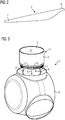
- Fig. 2 shows a rotor blade 5.
- the rotor blade 5 comprises an aerodynamically designed portion 7 which is shaped for optimum exploitation of the wind energy and a blade root 8 for connecting the rotor blade 5 to the hub 6.
- Fig. 3 shows a perspective partial view of the rotor 2 of the wind turbine 1. Accordingly, a first portion and a second portion which is connectable to the first portion is provided.
- the first portion may have a mass of at least 1 ton, 5 tons, 10 tons, 50 tons, 100 tons or 1500 tons.
- the second portion may have a mass of at least 1 ton, 5 tons, 10 tons, 50 tons, 100 tons or 1500 tons.
- the first portion is the hub 6 and the second portion is the blade 5.
- a spring element 11 and a further spring element 12 which are connected to the hub 6 are provided.
- the spring elements 11, 12 protrude from the hub 6, wherein the spring elements 11, 12 are configured to guide the blade 5 towards the hub 6, and wherein the spring elements 11, 12 are configured to be deformed while the blade 5 is guided towards the hub 6.
- the spring elements 11, 12 may be made of metal, in particular steel or aluminum, or plastic material, in particular rubber.
- the wind turbine 1 comprises stiff guiding elements 13 connected to the blade root 8 and protruding therefrom.
- the stiff guiding elements 13 are guiding pins or bolts.
- the stiff guiding elements 13 protrude less than 0.5 m, 0.25 m, 0.15 m or 0.1 m from the blade root 8.
- the hub 6 comprises holes (not shown) corresponding to the guiding elements 13.
- the holes and the guiding elements 13 are configured to form a form-fit connection.
- the spring elements 11, 12 engage into an inner space 14 of the blade root 8 which is surrounded by an inner surface 15 of the blade root 8. Then, the blade 5 may be guided towards the hub 6 in fitting direction X by means of the spring elements 11, 12. During guiding of the blade 5 the spring elements 11, 12 are deformed and/or bended to a radially inner direction R which is perpendicular to the fitting direction X.
- the first portion may be a tower section 9, 10, a nacelle section, a generator, a hub section or a blade section 8 and the second portion may be a tower section 9, 10, a nacelle section, a generator, a hub section or a blade section 8.
- Fig. 4 shows a cross-sectional view IV - IV of Fig. 1 .
- the spring elements 11, 12 are connected, in particular by means of bolts, to a flange 16 of the hub 6.
- the spring elements 11, 12 protrude by a length L1 from the hub 6.
- the length L1 may be at least 0.2, 0.3, 0.4, 0.5 m, 1 m, 2 m or 3 m.
- the spring elements 11, 12 further protrude from the flange 16 by a length L2.
- the length L2 may be at least 0.5 m, 1 m, 2 m, 3 m or 4 m.
- the blade 5 further comprises a housing or outer shell 17 having the inner surface 15.
- the spring elements 11, 12 are pushed to a respective radially inner direction R by the inner surface 15 and are pretensioned against the respective radially inner direction R.
- a distance A between the first and the second spring element 11, 12 starting from ends 18, 19 of the spring elements 11, 12 increases in fitting direction X.
- fitting the spring elements 11, 12 to the inner space 14 is facilitated and the effectiveness of guiding increases in fitting direction X.
- Fig. 5 shows a side view of the spring element 11.
- the spring element 11 comprises a first spring portion 20 and a second spring portion 21.
- An angle ⁇ between the first spring portion 20 and the second spring portion 21 is between 100° and 170°, 110° and 160°, 120° and 150° or 130° and 140°.
- the spring element 11 comprises a connecting portion 22 which is arranged between the first spring portion 20 and the second spring portion 21 and which connects the first spring portion 20 to the second spring portion 21.
- the connecting portion 22 contacts for example the inner surface 15 (see Fig. 4 ).
- the connecting portion 22 may be a buckled portion or a corner portion of the spring element 11.
- the first and the second spring portions 21, 22 may be provided as straight beam portions.
- a flange portion 24 is provided to be connected to the flange 16 (see Fig. 4 ).
- the portions 20, 21, 22, 24 may be provided as one piece element.
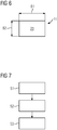
- Fig. 6 shows a cross-sectional view VI - VI of the spring element 11, in particular of the first spring portion 20.
- a cross-section 23 of the spring element 11 may have an essentially rectangular shape.
- a length B1 of the cross section 23 may be smaller than a width B2 of the cross-section 23.
- Width B2 may be less than 75%, 50% or 25% of length B1.
- Fig. 7 shows a schematic block diagram of a method for assembling the wind turbine 1.
- a first portion, a second portion and a spring element 11, 12 which is connected to the first portion and which protrudes therefrom is provided.
- the second portion is guided towards the first portion by means of the spring element 11, 12, wherein the spring element 11, 12 is deformed while guiding the second portion towards first portion.
- the step S2 preferably comprises a first step of guiding the second portion towards the first portion by means of an elastic guide (spring element 11, 12) having a long reach and a second step of guiding the second portion towards the first portion additionally or merely by means of a stiff guiding (stiff guiding elements and corresponding holes) having a short reach.
- a step S3 the second portion is connected and fixed to the first portion.
Landscapes
- Engineering & Computer Science (AREA)
- Life Sciences & Earth Sciences (AREA)
- Sustainable Development (AREA)
- Sustainable Energy (AREA)
- Chemical & Material Sciences (AREA)
- Combustion & Propulsion (AREA)
- Mechanical Engineering (AREA)
- General Engineering & Computer Science (AREA)
- Wind Motors (AREA)
Description
- The present invention relates to wind turbine and a method for assembling the wind turbine.
- Modern wind turbine rotor blades are built from fiber-reinforced plastics. A rotor blade typically comprises an airfoil having a rounded leading edge and a sharp trailing edge. The rotor blade is connected with its blade root to a hub of the wind turbine. The rotor blade is connected to the hub by means of a pitch bearing that allows a pitch movement of the rotor blade. The pitch bearing normally is a rolling element bearing. A longer rotor blade experiences more forces of the wind that interacts with the rotor blade. The forces are transferred over the pitch bearing of the rotor blade to the hub.
- When assembling a wind turbine, in particular connecting the blade to hub, e.g. one scenario is that bolts or guiding pins needs to penetrate holes which e.g. have just a few millimeters (mm) of clearance. Such an operation may be difficult since for example it is performed on site in heights of e.g. 50 to 150 meters (m). Such operations may be more difficult due to the movements which will inevitably be present at respective heights. These movements may have a magnitude between 50 and 500 mm.
-
WO2013027048 discloses an alignment apparatus for aligning a first component having an internal flange at one end with a second corresponding component, comprising: a support part, at least one attachment part for mounting the support part inside the first component and an elongate guide member. - It is one object of the present invention to provide an improved wind turbine.
- Accordingly, a wind turbine is provided. The wind turbine comprises a first portion, a second portion which is connectable, in particular connected, to the first portion, and a spring element which is connected to the first portion and which protrudes therefrom, wherein the spring element is configured to guide the second portion towards the first portion, and wherein the spring element is configured to be deformed while the second portion is guided towards the first portion.
- The advantages of the wind turbine are the following. Assembly operations are simplified since an elastic guiding system is provided which reduces movements between portions to be connected. In particular, a duration of assembly operations may be reduced. Thus, costs may also be reduced. Further, stacks between the first portion and the second portion may be avoided since an early elastic connection between the first and the second portion is provided which prevents impulsive relative movements between the first and the second portion.
- The spring element is configured to guide the second portion towards the first portion while the second portion is moved towards the first portion for connecting. Preferably, the spring element is configured to be deformed merely elastically while the second portion is guided towards the first portion. The spring element interacts e.g. with an inner surface of a housing or an outer shell of the second portion during a guiding movement.
- In particular, the second portion has a fitting direction towards the first portion, wherein the spring element is deformed or bended essentially perpendicular to the fitting direction while the second portion being guided towards the first portion.
- Preferably, in the connected status of the first and the second portion the spring element protrudes in an inner space of the second portion. In particular, in the connected status of the first and the second portion the spring element is elastically pretensioned e.g. perpendicular to the fitting direction and/or e.g. to a radial direction.
- "Wind turbine" presently refers to an apparatus converting the wind's kinetic energy into rotational energy, which may again be converted to electrical energy by the apparatus. According to an embodiment, the spring element protrudes at least 0.5 m, 1 m, 2 m or 3 m from the first portion.
- This has the advantage that fitting the spring element into the inner space of the second portion may be performed at a respective distance between the first and the second portion. Additionally or alternatively, the spring element may protrude at least 0.5 m, 1 m, 2 m or 3 m from a connection interface to the first portion. Such a connection interface e.g. may be provided at a flange of the first portion.
- According to a further embodiment, the first portion has a mass of at least 1 ton, 5 tons, 10 tons, 50 tons, 100 tons or 1500 tons and/or the second portion has a mass of at least 1 ton, 5 tons, 10 tons, 50 tons, 100 tons or 1500 tons.
- This has the advantage that heavy portions may by connected easily and with a reduced expenditure of time. In particular, the mass of the first portion may be between 10 to 1500 tons and/or the mass of the second portion may be between 10 to 1500 tons.
- According to a further embodiment, the spring element is made of metal, in particular steel or aluminum, or plastic material, in particular rubber.
- In particular, the steel may be a spring steel. This has the advantage that enough elasticity may be provided and that a stiff behavior which may cause brittle failure may be avoided.
- According to a further embodiment, the wind turbine comprises stiff guiding elements connected to the first portion or the second portion and protruding therefrom.
- This has the advantage that additionally a stiff guiding of the second portion may be executed. In particular, the stiff guiding elements are guiding pins or bolts. Preferably, holes corresponding to the stiff guiding elements are provided at the first portion or the second portion.
- According to a further embodiment, the stiff guiding elements protrude less than 0.5 m, 0.25 m, 0.15 m or 0.1 m from the first portion or the second portion.
- This has the advantage that in a first step the second portion is guided towards the first portion by means of an elastic guide (spring element) having a long reach and in a second step the second portion is guided towards the first portion additionally or merely by means of a stiff guiding (stiff guiding elements and corresponding holes) having a short reach. Thus, accurate connection of the first portion and the second portion is possible.
- According to a further embodiment, the wind turbine comprises a further spring element which is connected to the first portion and which protrudes therefrom, wherein the further spring element is configured to guide the second portion towards the first portion and is configured to be deformed while the second portion is guided towards the first portion.
- This has the advantage that a well-defined guiding movement of the second portion relative to the first portion may be executed. Preferably, the spring element is a first spring element and the further spring element is a second spring element. In particular, three, four or five, preferably identical, spring elements are provided. The spring elements may be identical.
- According to a further embodiment, the first portion is a hub and the second portion is a blade.
- This has the advantage that a mounting process of the blade to the hub may be improved.
- According to a further embodiment, the first portion is a tower section, a nacelle section, a generator, a hub section or a blade section and the second portion is a tower section, a nacelle section, a generator, a hub section or a blade section.
- According to a the invention the spring element comprises a first spring portion and a second spring portion, wherein an angle between the first spring portion and the second spring portion is between 100° and 170°, 110° and 160°, 120° and 150° or 130° and 140°.
- Thus, elastic bending between the first spring portion and the second spring portion is facilitated. Preferable, the further spring element is identical to the spring element. In particular, the spring element and the further spring element are arranged opposite to each other, wherein the first spring portion of the spring element and a first spring portion of the further spring element are bended towards each other such that a tapered guide is provided.
- According to a further embodiment, the spring element comprises a connecting portion which is arranged between the first spring portion and the second spring portion and which connects the first spring portion to the second spring portion, wherein the connecting portion contacts the second portion.
- In particular, the connecting portion may be a buckled portion or a corner portion of the spring element, wherein the first and the second spring portions may be provided as straight beam portions.
- Further, a method for assembling a wind turbine, in particular such a wind turbine blade, is provided. The method comprises the steps: a) providing a first portion, a second portion and a spring element which is connected to the first portion and which protrudes therefrom, b) guiding the second portion towards the first portion by means of the spring element, wherein the spring element is deformed while guiding the second portion towards first portion, and c) connecting the second portion to the first portion.
- The embodiments and features described with reference to the apparatus of the present invention apply mutatis mutandis to the method of the present invention.
- Further possible implementations or alternative solutions of the invention also encompass combinations - that are not explicitly mentioned herein - of features described above or below with regard to the embodiments. The person skilled in the art may also add individual or isolated aspects and features to the most basic form of the invention.
- Further embodiments, features and advantages of the present invention will become apparent from the subsequent description and dependent claims, taken in conjunction with the accompanying drawings, in which:
-
Fig. 1 shows a perspective view of a wind turbine according to one embodiment; -
Fig. 2 shows a perspective view of a wind turbine blade of the wind turbine according toFig. 1 ; -
Fig. 3 shows a perspective partial view of a rotor of the wind turbine according toFig. 1 . -
Fig. 4 shows a cross-sectional view IV - IV ofFig. 1 ; -
Fig. 5 shows a side view of a spring element of the wind turbine according toFig. 1 ; -
Fig. 6 shows a cross-sectional view VI - VI ofFig. 5 ; and -
Fig. 7 shows a schematic block diagram of a method for assembling a wind turbine. - In the Figures, like reference numerals designate like or functionally equivalent elements, unless otherwise indicated.
-
Fig. 1 shows a wind turbine 1. The wind turbine 1 comprises a rotor 2 connected to a generator (not shown) arranged inside a nacelle 3. The nacelle 3 is arranged at the upper end of atower 4 of the wind turbine 1. Thetower 4 may comprise afirst tower section 9 and asecond tower section 10 which is connected to thefirst tower section 9. - The rotor 2 comprises three
rotor blades 5. Therotor blades 5 are connected to ahub 6 of the wind turbine 1. Rotors 2 of this kind may have diameters ranging from, for example, 30 to 200 meters or even more. Therotor blades 5 are subjected to high wind loads. At the same time, therotor blades 5 need to be lightweight. For these reasons,rotor blades 5 in modern wind turbines 1 are manufactured from fiber-reinforced composite materials. Therein, glass fibers are generally preferred over carbon fibers for cost reasons. Oftentimes, glass fibers in the form of unidirectional fiber mats are used. -
Fig. 2 shows arotor blade 5. Therotor blade 5 comprises an aerodynamically designed portion 7 which is shaped for optimum exploitation of the wind energy and a blade root 8 for connecting therotor blade 5 to thehub 6. -
Fig. 3 shows a perspective partial view of the rotor 2 of the wind turbine 1. Accordingly, a first portion and a second portion which is connectable to the first portion is provided. The first portion may have a mass of at least 1 ton, 5 tons, 10 tons, 50 tons, 100 tons or 1500 tons. The second portion may have a mass of at least 1 ton, 5 tons, 10 tons, 50 tons, 100 tons or 1500 tons. - In this case the first portion is the
hub 6 and the second portion is theblade 5. Further, aspring element 11 and afurther spring element 12 which are connected to thehub 6 are provided. Thespring elements hub 6, wherein thespring elements blade 5 towards thehub 6, and wherein thespring elements blade 5 is guided towards thehub 6. - The
spring elements stiff guiding elements 13 connected to the blade root 8 and protruding therefrom. In particular, thestiff guiding elements 13 are guiding pins or bolts. Thestiff guiding elements 13 protrude less than 0.5 m, 0.25 m, 0.15 m or 0.1 m from the blade root 8. Thehub 6 comprises holes (not shown) corresponding to the guidingelements 13. The holes and the guidingelements 13 are configured to form a form-fit connection. - When the
blade 5 is moved towards thehub 6 in a fitting direction X during an assembly process, first thespring elements inner space 14 of the blade root 8 which is surrounded by aninner surface 15 of the blade root 8. Then, theblade 5 may be guided towards thehub 6 in fitting direction X by means of thespring elements blade 5 thespring elements - Alternatively, the first portion may be a
tower section tower section -
Fig. 4 shows a cross-sectional view IV - IV ofFig. 1 . Thespring elements flange 16 of thehub 6. Thespring elements hub 6. The length L1 may be at least 0.2, 0.3, 0.4, 0.5 m, 1 m, 2 m or 3 m. Thespring elements flange 16 by a length L2. The length L2 may be at least 0.5 m, 1 m, 2 m, 3 m or 4 m. - The
blade 5 further comprises a housing orouter shell 17 having theinner surface 15. Thespring elements inner surface 15 and are pretensioned against the respective radially inner direction R. A distance A between the first and thesecond spring element spring elements spring elements inner space 14 is facilitated and the effectiveness of guiding increases in fitting direction X. -
Fig. 5 shows a side view of thespring element 11. Thespring element 11 comprises afirst spring portion 20 and asecond spring portion 21. An angle α between thefirst spring portion 20 and thesecond spring portion 21 is between 100° and 170°, 110° and 160°, 120° and 150° or 130° and 140°. - Further, the
spring element 11 comprises a connectingportion 22 which is arranged between thefirst spring portion 20 and thesecond spring portion 21 and which connects thefirst spring portion 20 to thesecond spring portion 21. The connectingportion 22 contacts for example the inner surface 15 (seeFig. 4 ). - The connecting
portion 22 may be a buckled portion or a corner portion of thespring element 11. The first and thesecond spring portions flange portion 24 is provided to be connected to the flange 16 (seeFig. 4 ). Theportions -
Fig. 6 shows a cross-sectional view VI - VI of thespring element 11, in particular of thefirst spring portion 20. Across-section 23 of thespring element 11 may have an essentially rectangular shape. A length B1 of thecross section 23 may be smaller than a width B2 of thecross-section 23. Width B2 may be less than 75%, 50% or 25% of length B1. Thus, bending of thespring element 11 around the width B2 efforts relatively small forces such that deformation is facilitated. - It is understood that all features mentioned with regard to the
first spring element 11 also may be provided with regard to thesecond spring element 12. -
Fig. 7 shows a schematic block diagram of a method for assembling the wind turbine 1. - In a step S1 a first portion, a second portion and a
spring element spring element spring element - The step S2 preferably comprises a first step of guiding the second portion towards the first portion by means of an elastic guide (
spring element 11, 12) having a long reach and a second step of guiding the second portion towards the first portion additionally or merely by means of a stiff guiding (stiff guiding elements and corresponding holes) having a short reach. - In a step S3 the second portion is connected and fixed to the first portion.
- Although the present invention has been described in accordance with preferred embodiments, it is obvious for the person skilled in the art that modifications are possible in all embodiments. The protection scope being defined by the patent claims.
- It is understood that all features explained for the wind turbine 1 regarding
Fig. 1 to Fig. 6 are also provided for the method ofFig. 7 .
Claims (11)
- A wind turbine (1), comprising
a first portion (6, 9),
a second portion (5, 10) which is connectable to the first portion (6, 9), and
a spring element (11) which is connected to the first portion (6, 9) and which protrudes therefrom, wherein the spring element (11) is configured to guide the second portion (5, 10) towards the first portion (6, 9) and, and wherein the spring element (11) is configured to be deformed while the second portion (5, 10) is guided towards the first portion (6, 9) characterized in that the spring element (11) comprises a first spring portion (20) and a second spring portion (21), wherein an angle (α) between the first spring portion (20) and the second spring portion (21) is between 100° and 170°, 110° and 160°, 120° and 150° or 130° and 140°. - The wind turbine according to claim 1,
wherein the spring element (11) protrudes at least 0.5 m, 1 m, 2 m or 3 m from the first portion (6, 9). - The wind turbine according to claim 1 or 2,
wherein the first portion (6, 9) has a mass of at least 1 ton, 5 tons, 10 tons, 50 tons, 100 tons or 1500 tons and/or the second portion (5, 10) has a mass of at least 1 ton, 5 tons, 10 tons, 50 tons, 100 tons or 1500 tons. - The wind turbine according to one of claims 1 - 3,
wherein the spring element (11) is made of metal, in particular steel or aluminum, or plastic material, in particular rubber. - The wind turbine according to one of claims 1 - 4,
further comprising stiff guiding elements (13) connected to the first portion (6, 9) or the second portion (5, 10) and protruding therefrom. - The wind turbine according to claim 5,
wherein the stiff guiding elements (13) protrude less than 0.5 m, 0.25 m, 0.15 m or 0.1 m from the first portion (6, 9) or the second portion (5, 10). - The wind turbine according to one of claims 1 - 6,
further comprising a further spring element (12) which is connected to the first portion (6, 9) and which protrudes therefrom, wherein the further spring element (12) is configured to guide the second portion (5, 10) towards the first portion (6, 9) and is configured to be deformed while the second portion (5, 10) is guided towards the first portion (6, 9). - The wind turbine according to one of claims 1 - 7,
wherein the first portion is a hub (6) and the second portion is a blade (5). - The wind turbine according to one of claims 1 - 7,
wherein the first portion is a tower section (9), a nacelle section, a generator, a hub section or a blade section (8) and the second portion is a tower section (10), a nacelle section, a generator, a hub section or a blade section (8). - The wind turbine according to one of claims 1 - 9,
wherein the spring element (11) comprises a connecting portion (22) which is arranged between the first spring portion (20) and the second spring portion (21) and which connects the first spring portion (20) to the second spring portion (21), wherein the connecting portion (22) contacts the second portion (5, 10). - A method for assembling a wind turbine (1), according to any of claims 1-10, comprising the steps:a) providing (S1) a first portion (6, 9), a second portion (5, 10) and a spring element (11, 12) which is connected to the first portion (6, 9) and which protrudes therefrom,b) guiding (S2) the second portion (5, 10) towards the first portion (6, 9) by means of the spring element (11, 12), wherein the spring element (11, 12) is deformed while guiding the second portion (5, 10) towards first portion (6, 9), andc) connecting (S3) the second portion (5, 10) to the first portion (6, 9).
Priority Applications (10)
| Application Number | Priority Date | Filing Date | Title |
|---|---|---|---|
| DK17205064.3T DK3492734T3 (en) | 2017-12-04 | 2017-12-04 | Wind turbine and method of assembling a wind turbine |
| EP17205064.3A EP3492734B1 (en) | 2017-12-04 | 2017-12-04 | Wind turbine and method for assembling a wind turbine |
| ES17205064T ES2808929T3 (en) | 2017-12-04 | 2017-12-04 | Wind turbine and procedure for assembling a wind turbine |
| US16/767,253 US11454207B2 (en) | 2017-12-04 | 2018-10-17 | Wind turbine and method for assembling a wind turbine |
| AU2018381757A AU2018381757B2 (en) | 2017-12-04 | 2018-10-17 | Wind turbine and method for assembling a wind turbine |
| JP2020530300A JP6949229B2 (en) | 2017-12-04 | 2018-10-17 | Wind Turbines and Methods for Assembling Wind Turbines |
| CA3084236A CA3084236C (en) | 2017-12-04 | 2018-10-17 | Wind turbine and method for assembling a wind turbine |
| MX2020005643A MX2020005643A (en) | 2017-12-04 | 2018-10-17 | Wind turbine and method for assembling a wind turbine. |
| CN201880078545.0A CN111417779B (en) | 2017-12-04 | 2018-10-17 | Wind turbine and method for assembling a wind turbine |
| PCT/EP2018/078353 WO2019110180A1 (en) | 2017-12-04 | 2018-10-17 | Wind turbine and method for assembling a wind turbine |
Applications Claiming Priority (1)
| Application Number | Priority Date | Filing Date | Title |
|---|---|---|---|
| EP17205064.3A EP3492734B1 (en) | 2017-12-04 | 2017-12-04 | Wind turbine and method for assembling a wind turbine |
Publications (2)
| Publication Number | Publication Date |
|---|---|
| EP3492734A1 EP3492734A1 (en) | 2019-06-05 |
| EP3492734B1 true EP3492734B1 (en) | 2020-06-10 |
Family
ID=60569767
Family Applications (1)
| Application Number | Title | Priority Date | Filing Date |
|---|---|---|---|
| EP17205064.3A Active EP3492734B1 (en) | 2017-12-04 | 2017-12-04 | Wind turbine and method for assembling a wind turbine |
Country Status (10)
| Country | Link |
|---|---|
| US (1) | US11454207B2 (en) |
| EP (1) | EP3492734B1 (en) |
| JP (1) | JP6949229B2 (en) |
| CN (1) | CN111417779B (en) |
| AU (1) | AU2018381757B2 (en) |
| CA (1) | CA3084236C (en) |
| DK (1) | DK3492734T3 (en) |
| ES (1) | ES2808929T3 (en) |
| MX (1) | MX2020005643A (en) |
| WO (1) | WO2019110180A1 (en) |
Cited By (1)
| Publication number | Priority date | Publication date | Assignee | Title |
|---|---|---|---|---|
| EP4001635A1 (en) | 2020-11-13 | 2022-05-25 | Wobben Properties GmbH | Wind turbine, rotor hub for a wind turbine and related rotor assembly |
Families Citing this family (4)
| Publication number | Priority date | Publication date | Assignee | Title |
|---|---|---|---|---|
| US10837425B2 (en) * | 2017-09-11 | 2020-11-17 | Dalian University Of Technology | Hub mating mechanism applicable to single blade installation of offshore wind turbines |
| DK3770420T3 (en) * | 2019-07-23 | 2022-09-19 | Siemens Gamesa Renewable Energy As | Method for connecting a blade to a hub and method for disconnecting a blade from a hub |
| EP4303430A1 (en) | 2022-07-04 | 2024-01-10 | Siemens Gamesa Renewable Energy A/S | Wind turbine assembly system and method for assembling a wind turbine |
| WO2025082578A1 (en) * | 2023-10-17 | 2025-04-24 | Vestas Wind Systems A/S | A wind turbine blade handling method |
Family Cites Families (40)
| Publication number | Priority date | Publication date | Assignee | Title |
|---|---|---|---|---|
| US6568712B1 (en) * | 2000-06-19 | 2003-05-27 | Aaron, Iii John W. | Alignment tool for pipe couplings |
| US6782667B2 (en) * | 2000-12-05 | 2004-08-31 | Z-Tek, Llc | Tilt-up and telescopic support tower for large structures |
| CN2709692Y (en) * | 2004-05-19 | 2005-07-13 | 南京思瑞杰机电工程设备配套有限公司 | Connection piece for glass fibre composite super blast pipe and lining adapter |
| CN2828366Y (en) | 2005-01-24 | 2006-10-18 | 雷良榆 | Cylindrical rotor horizontal axis wind-mill generator |
| JP5032527B2 (en) * | 2008-07-17 | 2012-09-26 | 東尾メック株式会社 | Pipe fitting |
| US8728045B2 (en) | 2009-03-04 | 2014-05-20 | Spiracur Inc. | Devices and methods to apply alternating level of reduced pressure to tissue |
| WO2011018747A2 (en) | 2009-08-08 | 2011-02-17 | Palma Bernardo Angel B | Universal renewable global energy machine nature systems |
| CN101994641A (en) | 2009-08-27 | 2011-03-30 | 杨林荣 | Blade unloading device of wind driven generator |
| CN201448183U (en) | 2009-08-27 | 2010-05-05 | 杨林荣 | Wind turbine blade unloading device |
| CA2784625A1 (en) | 2009-11-30 | 2011-06-03 | Clipper Windpower, Inc. | Wind turbine blade lowering apparatus |
| DK2526288T3 (en) | 2010-01-21 | 2017-08-21 | Vestas Wind Sys As | SEGMENTED ROTOR LEFT EXTENSION PART |
| DK2369174T3 (en) | 2010-03-09 | 2013-03-11 | Lm Glasfiber As | A method for crane-free installation or removal of a wind turbine blade on a wind turbine |
| GB2483678B (en) | 2010-09-15 | 2013-09-18 | Vestas Wind Sys As | An apparatus for and method of mounting wind turbine blades on a wind turbine tower |
| ES2411459T3 (en) | 2010-09-27 | 2013-07-05 | Siemens Aktiengesellschaft | Method, assembly and system for mounting wind turbine blades in a wind turbine hub |
| CN201874748U (en) | 2010-11-30 | 2011-06-22 | 窦忠义 | Centrifugal speed-regulating pitch variable mechanism of wind driven generator |
| CN201908790U (en) | 2011-03-15 | 2011-07-27 | 宁波锦浪新能源科技有限公司 | Wide-top blade capable of self adjusting blade pitch |
| CN102146881B (en) | 2011-04-22 | 2013-03-06 | 江阴江源新能源科技有限公司 | Intelligent flexible pitch-changing device for wind power generator |
| CN202047948U (en) | 2011-05-04 | 2011-11-23 | 株洲时代新材料科技股份有限公司 | Elastic element for warping board hub of two-blade wind power generator unit |
| GB2493948B (en) * | 2011-08-24 | 2013-11-06 | Technip France | Tower section alignment apparatus and system |
| US20130171002A1 (en) * | 2011-12-29 | 2013-07-04 | Clipper Windpower, Llc | Hybrid Wind Turbine Tower with Integrated Yaw Bearing System |
| EP2893187B1 (en) * | 2012-09-03 | 2020-11-04 | X-Tower Constructions GmbH | Tower construction of a wind turbine and method for stabilizing a tower construction of a wind turbine |
| WO2014075686A1 (en) * | 2012-11-15 | 2014-05-22 | Vestas Wind Systems A/S | Method and device for aligning tower sections |
| EP2923017B1 (en) | 2012-11-15 | 2016-10-26 | Vestas Wind Systems A/S | Tower section and a method for a tower section |
| CN103016271B (en) | 2012-12-27 | 2015-04-15 | 华北电力大学 | Wind generating set with expandable working wind speed range |
| CN103047095A (en) | 2013-01-07 | 2013-04-17 | 国电联合动力技术有限公司 | Elastic unit for wind turbine generator transmission chains |
| DK177908B1 (en) * | 2013-02-26 | 2014-12-15 | Envision Energy Denmark Aps | Tower assembly system for wind turbines and method thereof |
| CN103527421B (en) | 2013-11-08 | 2017-02-08 | 广东明阳风电产业集团有限公司 | Blade lightning protection device of offshore wind generating set |
| DK2918969T3 (en) * | 2014-03-12 | 2019-01-28 | Siemens Ag | Device and method for aligning two components of a wind turbine |
| DK2998569T3 (en) * | 2014-09-22 | 2017-10-23 | Siemens Ag | Device for fitting part of a wind turbine |
| US9777704B2 (en) * | 2014-11-03 | 2017-10-03 | General Electric Company | Rotor blade assembly for a wind turbine having variable-length blade bolts |
| CN204407018U (en) * | 2014-12-05 | 2015-06-17 | 上海核工程研究设计院 | The syndeton of a kind of removable upper base and guide pipe |
| CN104819101A (en) | 2015-04-09 | 2015-08-05 | 成都绿迪科技有限公司 | Wind power generation device |
| DK3098443T3 (en) * | 2015-05-26 | 2019-11-04 | Siemens Gamesa Renewable Energy As | Coupling device in the field of wind turbines |
| CN204805037U (en) | 2015-06-08 | 2015-11-25 | 朱明志 | Wind -driven generator |
| CN104912749B (en) | 2015-06-30 | 2017-11-17 | 河北工业大学 | A kind of wind-driven generator automatic adjusument hub unit |
| CN205190125U (en) | 2015-11-06 | 2016-04-27 | 优利康达(天津)科技有限公司 | Wind generating set with dustproof function |
| CN205297833U (en) | 2016-01-06 | 2016-06-08 | 包头市金陵风电科技有限公司 | Novel lightning protection of aerogenerator blade is connected device |
| JP6967537B2 (en) * | 2016-06-29 | 2021-11-17 | ヴェスタス ウィンド システムズ エー/エス | Methods used to install equipment units in assemblies, equipment packages, and wind turbine towers |
| DK3545192T3 (en) * | 2016-11-23 | 2021-10-18 | Vestas Offshore Wind As | METHOD AND DEVICE FOR BRINGING STRUCTURAL WIND TURBINES IN LINE |
| CN108590950B (en) | 2018-07-06 | 2023-12-26 | 三一重能股份有限公司 | Wind generating set and wind wheel thereof |
-
2017
- 2017-12-04 ES ES17205064T patent/ES2808929T3/en active Active
- 2017-12-04 DK DK17205064.3T patent/DK3492734T3/en active
- 2017-12-04 EP EP17205064.3A patent/EP3492734B1/en active Active
-
2018
- 2018-10-17 MX MX2020005643A patent/MX2020005643A/en unknown
- 2018-10-17 WO PCT/EP2018/078353 patent/WO2019110180A1/en not_active Ceased
- 2018-10-17 JP JP2020530300A patent/JP6949229B2/en active Active
- 2018-10-17 US US16/767,253 patent/US11454207B2/en active Active
- 2018-10-17 CN CN201880078545.0A patent/CN111417779B/en active Active
- 2018-10-17 CA CA3084236A patent/CA3084236C/en active Active
- 2018-10-17 AU AU2018381757A patent/AU2018381757B2/en active Active
Non-Patent Citations (1)
| Title |
|---|
| None * |
Cited By (1)
| Publication number | Priority date | Publication date | Assignee | Title |
|---|---|---|---|---|
| EP4001635A1 (en) | 2020-11-13 | 2022-05-25 | Wobben Properties GmbH | Wind turbine, rotor hub for a wind turbine and related rotor assembly |
Also Published As
| Publication number | Publication date |
|---|---|
| MX2020005643A (en) | 2020-11-12 |
| US20200355156A1 (en) | 2020-11-12 |
| JP2021505809A (en) | 2021-02-18 |
| AU2018381757A1 (en) | 2020-06-11 |
| US11454207B2 (en) | 2022-09-27 |
| JP6949229B2 (en) | 2021-10-13 |
| DK3492734T3 (en) | 2020-08-10 |
| CN111417779A (en) | 2020-07-14 |
| CA3084236A1 (en) | 2019-06-13 |
| CN111417779B (en) | 2023-02-21 |
| WO2019110180A1 (en) | 2019-06-13 |
| CA3084236C (en) | 2023-01-24 |
| AU2018381757B2 (en) | 2021-04-29 |
| ES2808929T3 (en) | 2021-03-02 |
| EP3492734A1 (en) | 2019-06-05 |
Similar Documents
| Publication | Publication Date | Title |
|---|---|---|
| EP3492734B1 (en) | Wind turbine and method for assembling a wind turbine | |
| US8714928B2 (en) | Rotor assembly for a wind turbine and method of assembling the same | |
| CA3002904C (en) | Wind turbine rotor blade and wind turbine | |
| US20150354531A1 (en) | Root bushing for a blade root of a wind turbine rotor blade, a blade root, a wind turbine rotor blade and a wind turbine | |
| EP3599374B1 (en) | Wind turbine blade comprising a composite material and a method for producing a wind turbine blade | |
| EP2653719A2 (en) | Hub for wind turbine rotor | |
| EP2952734B1 (en) | A root bushing for a blade root of a wind turbine rotor blade, a blade root, a wind turbine rotor blade and a wind turbine | |
| EP3267033B1 (en) | A wind turbine | |
| US9261074B2 (en) | Variable bolt parameters for a wind turbine rotor blade | |
| EP3894689B1 (en) | Segmented rotor blade having maximized overall pre-bend via an increased pre-bend in a blade tip segment thereof | |
| US20120027618A1 (en) | Angled blade root | |
| EP2878806A1 (en) | Windmill blade and method for manufacturing same | |
| WO2018215037A1 (en) | Blade with pre-deflection for downwind type wind turbine | |
| EP2952738A1 (en) | A root bushing for a blade root of a wind turbine rotor blade, a blade root, a wind turbine rotor blade, a wind turbine and a method for manufacturing a root bushing | |
| JP7645025B1 (en) | Positioning structure and wind power generation device | |
| US9664174B2 (en) | Aerodynamic root adapters for wind turbine rotor blades | |
| KR20140012409A (en) | Wind power generator | |
| EP3788256B1 (en) | A rotor for a wind turbine with a pitch bearing unit |
Legal Events
| Date | Code | Title | Description |
|---|---|---|---|
| PUAI | Public reference made under article 153(3) epc to a published international application that has entered the european phase |
Free format text: ORIGINAL CODE: 0009012 |
|
| STAA | Information on the status of an ep patent application or granted ep patent |
Free format text: STATUS: THE APPLICATION HAS BEEN PUBLISHED |
|
| AK | Designated contracting states |
Kind code of ref document: A1 Designated state(s): AL AT BE BG CH CY CZ DE DK EE ES FI FR GB GR HR HU IE IS IT LI LT LU LV MC MK MT NL NO PL PT RO RS SE SI SK SM TR |
|
| AX | Request for extension of the european patent |
Extension state: BA ME |
|
| STAA | Information on the status of an ep patent application or granted ep patent |
Free format text: STATUS: REQUEST FOR EXAMINATION WAS MADE |
|
| 17P | Request for examination filed |
Effective date: 20191119 |
|
| RBV | Designated contracting states (corrected) |
Designated state(s): AL AT BE BG CH CY CZ DE DK EE ES FI FR GB GR HR HU IE IS IT LI LT LU LV MC MK MT NL NO PL PT RO RS SE SI SK SM TR |
|
| GRAP | Despatch of communication of intention to grant a patent |
Free format text: ORIGINAL CODE: EPIDOSNIGR1 |
|
| STAA | Information on the status of an ep patent application or granted ep patent |
Free format text: STATUS: GRANT OF PATENT IS INTENDED |
|
| INTG | Intention to grant announced |
Effective date: 20200204 |
|
| GRAS | Grant fee paid |
Free format text: ORIGINAL CODE: EPIDOSNIGR3 |
|
| GRAA | (expected) grant |
Free format text: ORIGINAL CODE: 0009210 |
|
| STAA | Information on the status of an ep patent application or granted ep patent |
Free format text: STATUS: THE PATENT HAS BEEN GRANTED |
|
| AK | Designated contracting states |
Kind code of ref document: B1 Designated state(s): AL AT BE BG CH CY CZ DE DK EE ES FI FR GB GR HR HU IE IS IT LI LT LU LV MC MK MT NL NO PL PT RO RS SE SI SK SM TR |
|
| REG | Reference to a national code |
Ref country code: GB Ref legal event code: FG4D |
|
| REG | Reference to a national code |
Ref country code: AT Ref legal event code: REF Ref document number: 1279394 Country of ref document: AT Kind code of ref document: T Effective date: 20200615 Ref country code: CH Ref legal event code: EP |
|
| REG | Reference to a national code |
Ref country code: DE Ref legal event code: R096 Ref document number: 602017017929 Country of ref document: DE |
|
| REG | Reference to a national code |
Ref country code: IE Ref legal event code: FG4D |
|
| REG | Reference to a national code |
Ref country code: DK Ref legal event code: T3 Effective date: 20200804 |
|
| REG | Reference to a national code |
Ref country code: SE Ref legal event code: TRGR |
|
| REG | Reference to a national code |
Ref country code: FI Ref legal event code: FGE |
|
| REG | Reference to a national code |
Ref country code: NL Ref legal event code: FP |
|
| REG | Reference to a national code |
Ref country code: LT Ref legal event code: MG4D |
|
| PG25 | Lapsed in a contracting state [announced via postgrant information from national office to epo] |
Ref country code: GR Free format text: LAPSE BECAUSE OF FAILURE TO SUBMIT A TRANSLATION OF THE DESCRIPTION OR TO PAY THE FEE WITHIN THE PRESCRIBED TIME-LIMIT Effective date: 20200911 Ref country code: NO Free format text: LAPSE BECAUSE OF FAILURE TO SUBMIT A TRANSLATION OF THE DESCRIPTION OR TO PAY THE FEE WITHIN THE PRESCRIBED TIME-LIMIT Effective date: 20200910 Ref country code: LT Free format text: LAPSE BECAUSE OF FAILURE TO SUBMIT A TRANSLATION OF THE DESCRIPTION OR TO PAY THE FEE WITHIN THE PRESCRIBED TIME-LIMIT Effective date: 20200610 |
|
| PG25 | Lapsed in a contracting state [announced via postgrant information from national office to epo] |
Ref country code: BG Free format text: LAPSE BECAUSE OF FAILURE TO SUBMIT A TRANSLATION OF THE DESCRIPTION OR TO PAY THE FEE WITHIN THE PRESCRIBED TIME-LIMIT Effective date: 20200910 Ref country code: LV Free format text: LAPSE BECAUSE OF FAILURE TO SUBMIT A TRANSLATION OF THE DESCRIPTION OR TO PAY THE FEE WITHIN THE PRESCRIBED TIME-LIMIT Effective date: 20200610 Ref country code: RS Free format text: LAPSE BECAUSE OF FAILURE TO SUBMIT A TRANSLATION OF THE DESCRIPTION OR TO PAY THE FEE WITHIN THE PRESCRIBED TIME-LIMIT Effective date: 20200610 Ref country code: HR Free format text: LAPSE BECAUSE OF FAILURE TO SUBMIT A TRANSLATION OF THE DESCRIPTION OR TO PAY THE FEE WITHIN THE PRESCRIBED TIME-LIMIT Effective date: 20200610 |
|
| REG | Reference to a national code |
Ref country code: AT Ref legal event code: MK05 Ref document number: 1279394 Country of ref document: AT Kind code of ref document: T Effective date: 20200610 |
|
| PG25 | Lapsed in a contracting state [announced via postgrant information from national office to epo] |
Ref country code: AL Free format text: LAPSE BECAUSE OF FAILURE TO SUBMIT A TRANSLATION OF THE DESCRIPTION OR TO PAY THE FEE WITHIN THE PRESCRIBED TIME-LIMIT Effective date: 20200610 |
|
| PG25 | Lapsed in a contracting state [announced via postgrant information from national office to epo] |
Ref country code: AT Free format text: LAPSE BECAUSE OF FAILURE TO SUBMIT A TRANSLATION OF THE DESCRIPTION OR TO PAY THE FEE WITHIN THE PRESCRIBED TIME-LIMIT Effective date: 20200610 Ref country code: RO Free format text: LAPSE BECAUSE OF FAILURE TO SUBMIT A TRANSLATION OF THE DESCRIPTION OR TO PAY THE FEE WITHIN THE PRESCRIBED TIME-LIMIT Effective date: 20200610 Ref country code: IT Free format text: LAPSE BECAUSE OF FAILURE TO SUBMIT A TRANSLATION OF THE DESCRIPTION OR TO PAY THE FEE WITHIN THE PRESCRIBED TIME-LIMIT Effective date: 20200610 Ref country code: SM Free format text: LAPSE BECAUSE OF FAILURE TO SUBMIT A TRANSLATION OF THE DESCRIPTION OR TO PAY THE FEE WITHIN THE PRESCRIBED TIME-LIMIT Effective date: 20200610 Ref country code: EE Free format text: LAPSE BECAUSE OF FAILURE TO SUBMIT A TRANSLATION OF THE DESCRIPTION OR TO PAY THE FEE WITHIN THE PRESCRIBED TIME-LIMIT Effective date: 20200610 Ref country code: PT Free format text: LAPSE BECAUSE OF FAILURE TO SUBMIT A TRANSLATION OF THE DESCRIPTION OR TO PAY THE FEE WITHIN THE PRESCRIBED TIME-LIMIT Effective date: 20201012 Ref country code: CZ Free format text: LAPSE BECAUSE OF FAILURE TO SUBMIT A TRANSLATION OF THE DESCRIPTION OR TO PAY THE FEE WITHIN THE PRESCRIBED TIME-LIMIT Effective date: 20200610 |
|
| PG25 | Lapsed in a contracting state [announced via postgrant information from national office to epo] |
Ref country code: IS Free format text: LAPSE BECAUSE OF FAILURE TO SUBMIT A TRANSLATION OF THE DESCRIPTION OR TO PAY THE FEE WITHIN THE PRESCRIBED TIME-LIMIT Effective date: 20201010 Ref country code: SK Free format text: LAPSE BECAUSE OF FAILURE TO SUBMIT A TRANSLATION OF THE DESCRIPTION OR TO PAY THE FEE WITHIN THE PRESCRIBED TIME-LIMIT Effective date: 20200610 Ref country code: PL Free format text: LAPSE BECAUSE OF FAILURE TO SUBMIT A TRANSLATION OF THE DESCRIPTION OR TO PAY THE FEE WITHIN THE PRESCRIBED TIME-LIMIT Effective date: 20200610 |
|
| REG | Reference to a national code |
Ref country code: ES Ref legal event code: FG2A Ref document number: 2808929 Country of ref document: ES Kind code of ref document: T3 Effective date: 20210302 |
|
| REG | Reference to a national code |
Ref country code: DE Ref legal event code: R097 Ref document number: 602017017929 Country of ref document: DE |
|
| PLBE | No opposition filed within time limit |
Free format text: ORIGINAL CODE: 0009261 |
|
| STAA | Information on the status of an ep patent application or granted ep patent |
Free format text: STATUS: NO OPPOSITION FILED WITHIN TIME LIMIT |
|
| 26N | No opposition filed |
Effective date: 20210311 |
|
| PG25 | Lapsed in a contracting state [announced via postgrant information from national office to epo] |
Ref country code: SI Free format text: LAPSE BECAUSE OF FAILURE TO SUBMIT A TRANSLATION OF THE DESCRIPTION OR TO PAY THE FEE WITHIN THE PRESCRIBED TIME-LIMIT Effective date: 20200610 |
|
| REG | Reference to a national code |
Ref country code: CH Ref legal event code: PL |
|
| PG25 | Lapsed in a contracting state [announced via postgrant information from national office to epo] |
Ref country code: MC Free format text: LAPSE BECAUSE OF FAILURE TO SUBMIT A TRANSLATION OF THE DESCRIPTION OR TO PAY THE FEE WITHIN THE PRESCRIBED TIME-LIMIT Effective date: 20200610 |
|
| REG | Reference to a national code |
Ref country code: BE Ref legal event code: MM Effective date: 20201231 |
|
| PG25 | Lapsed in a contracting state [announced via postgrant information from national office to epo] |
Ref country code: IE Free format text: LAPSE BECAUSE OF NON-PAYMENT OF DUE FEES Effective date: 20201204 Ref country code: LU Free format text: LAPSE BECAUSE OF NON-PAYMENT OF DUE FEES Effective date: 20201204 |
|
| PG25 | Lapsed in a contracting state [announced via postgrant information from national office to epo] |
Ref country code: LI Free format text: LAPSE BECAUSE OF NON-PAYMENT OF DUE FEES Effective date: 20201231 Ref country code: CH Free format text: LAPSE BECAUSE OF NON-PAYMENT OF DUE FEES Effective date: 20201231 |
|
| PG25 | Lapsed in a contracting state [announced via postgrant information from national office to epo] |
Ref country code: MT Free format text: LAPSE BECAUSE OF FAILURE TO SUBMIT A TRANSLATION OF THE DESCRIPTION OR TO PAY THE FEE WITHIN THE PRESCRIBED TIME-LIMIT Effective date: 20200610 Ref country code: CY Free format text: LAPSE BECAUSE OF FAILURE TO SUBMIT A TRANSLATION OF THE DESCRIPTION OR TO PAY THE FEE WITHIN THE PRESCRIBED TIME-LIMIT Effective date: 20200610 |
|
| PG25 | Lapsed in a contracting state [announced via postgrant information from national office to epo] |
Ref country code: MK Free format text: LAPSE BECAUSE OF FAILURE TO SUBMIT A TRANSLATION OF THE DESCRIPTION OR TO PAY THE FEE WITHIN THE PRESCRIBED TIME-LIMIT Effective date: 20200610 |
|
| PG25 | Lapsed in a contracting state [announced via postgrant information from national office to epo] |
Ref country code: BE Free format text: LAPSE BECAUSE OF NON-PAYMENT OF DUE FEES Effective date: 20201231 |
|
| REG | Reference to a national code |
Ref country code: DE Ref legal event code: R082 Ref document number: 602017017929 Country of ref document: DE Representative=s name: SAUTHOFF, KARSTEN, DIPL.-ING. UNIV., DE |
|
| PGFP | Annual fee paid to national office [announced via postgrant information from national office to epo] |
Ref country code: NL Payment date: 20241224 Year of fee payment: 8 |
|
| PGFP | Annual fee paid to national office [announced via postgrant information from national office to epo] |
Ref country code: DK Payment date: 20250912 Year of fee payment: 9 |
|
| PGFP | Annual fee paid to national office [announced via postgrant information from national office to epo] |
Ref country code: DE Payment date: 20250731 Year of fee payment: 9 |
|
| PGFP | Annual fee paid to national office [announced via postgrant information from national office to epo] |
Ref country code: GB Payment date: 20251223 Year of fee payment: 9 |
|
| PGFP | Annual fee paid to national office [announced via postgrant information from national office to epo] |
Ref country code: FI Payment date: 20251222 Year of fee payment: 9 |
|
| PGFP | Annual fee paid to national office [announced via postgrant information from national office to epo] |
Ref country code: FR Payment date: 20251223 Year of fee payment: 9 |
|
| PGFP | Annual fee paid to national office [announced via postgrant information from national office to epo] |
Ref country code: TR Payment date: 20251113 Year of fee payment: 9 |
|
| PGFP | Annual fee paid to national office [announced via postgrant information from national office to epo] |
Ref country code: SE Payment date: 20251222 Year of fee payment: 9 |
|
| PGFP | Annual fee paid to national office [announced via postgrant information from national office to epo] |
Ref country code: ES Payment date: 20260122 Year of fee payment: 9 |