EP3492714A1 - Thermal energy recovery device - Google Patents
Thermal energy recovery device Download PDFInfo
- Publication number
- EP3492714A1 EP3492714A1 EP18201705.3A EP18201705A EP3492714A1 EP 3492714 A1 EP3492714 A1 EP 3492714A1 EP 18201705 A EP18201705 A EP 18201705A EP 3492714 A1 EP3492714 A1 EP 3492714A1
- Authority
- EP
- European Patent Office
- Prior art keywords
- oil
- flow passage
- expander
- mixed medium
- oil cooler
- Prior art date
- Legal status (The legal status is an assumption and is not a legal conclusion. Google has not performed a legal analysis and makes no representation as to the accuracy of the status listed.)
- Granted
Links
- 238000011084 recovery Methods 0.000 title claims abstract description 68
- 238000001816 cooling Methods 0.000 claims abstract description 65
- 238000011144 upstream manufacturing Methods 0.000 claims abstract description 9
- 239000007788 liquid Substances 0.000 claims description 38
- 239000012071 phase Substances 0.000 claims description 25
- 239000007791 liquid phase Substances 0.000 claims description 20
- 238000002309 gasification Methods 0.000 description 12
- 238000001514 detection method Methods 0.000 description 10
- 238000001704 evaporation Methods 0.000 description 6
- 230000008020 evaporation Effects 0.000 description 5
- 238000005461 lubrication Methods 0.000 description 5
- 238000010586 diagram Methods 0.000 description 4
- 230000007423 decrease Effects 0.000 description 3
- 239000012530 fluid Substances 0.000 description 3
- 239000000498 cooling water Substances 0.000 description 2
- 101001139126 Homo sapiens Krueppel-like factor 6 Proteins 0.000 description 1
- 101000661807 Homo sapiens Suppressor of tumorigenicity 14 protein Proteins 0.000 description 1
- 239000002826 coolant Substances 0.000 description 1
- 238000006073 displacement reaction Methods 0.000 description 1
- 238000010438 heat treatment Methods 0.000 description 1
- 238000010248 power generation Methods 0.000 description 1
Images




Classifications
-
- F—MECHANICAL ENGINEERING; LIGHTING; HEATING; WEAPONS; BLASTING
- F01—MACHINES OR ENGINES IN GENERAL; ENGINE PLANTS IN GENERAL; STEAM ENGINES
- F01K—STEAM ENGINE PLANTS; STEAM ACCUMULATORS; ENGINE PLANTS NOT OTHERWISE PROVIDED FOR; ENGINES USING SPECIAL WORKING FLUIDS OR CYCLES
- F01K23/00—Plants characterised by more than one engine delivering power external to the plant, the engines being driven by different fluids
- F01K23/02—Plants characterised by more than one engine delivering power external to the plant, the engines being driven by different fluids the engine cycles being thermally coupled
- F01K23/06—Plants characterised by more than one engine delivering power external to the plant, the engines being driven by different fluids the engine cycles being thermally coupled combustion heat from one cycle heating the fluid in another cycle
- F01K23/10—Plants characterised by more than one engine delivering power external to the plant, the engines being driven by different fluids the engine cycles being thermally coupled combustion heat from one cycle heating the fluid in another cycle with exhaust fluid of one cycle heating the fluid in another cycle
-
- F—MECHANICAL ENGINEERING; LIGHTING; HEATING; WEAPONS; BLASTING
- F01—MACHINES OR ENGINES IN GENERAL; ENGINE PLANTS IN GENERAL; STEAM ENGINES
- F01K—STEAM ENGINE PLANTS; STEAM ACCUMULATORS; ENGINE PLANTS NOT OTHERWISE PROVIDED FOR; ENGINES USING SPECIAL WORKING FLUIDS OR CYCLES
- F01K25/00—Plants or engines characterised by use of special working fluids, not otherwise provided for; Plants operating in closed cycles and not otherwise provided for
- F01K25/06—Plants or engines characterised by use of special working fluids, not otherwise provided for; Plants operating in closed cycles and not otherwise provided for using mixtures of different fluids
-
- F—MECHANICAL ENGINEERING; LIGHTING; HEATING; WEAPONS; BLASTING
- F01—MACHINES OR ENGINES IN GENERAL; ENGINE PLANTS IN GENERAL; STEAM ENGINES
- F01K—STEAM ENGINE PLANTS; STEAM ACCUMULATORS; ENGINE PLANTS NOT OTHERWISE PROVIDED FOR; ENGINES USING SPECIAL WORKING FLUIDS OR CYCLES
- F01K7/00—Steam engine plants characterised by the use of specific types of engine; Plants or engines characterised by their use of special steam systems, cycles or processes; Control means specially adapted for such systems, cycles or processes; Use of withdrawn or exhaust steam for feed-water heating
- F01K7/06—Steam engine plants characterised by the use of specific types of engine; Plants or engines characterised by their use of special steam systems, cycles or processes; Control means specially adapted for such systems, cycles or processes; Use of withdrawn or exhaust steam for feed-water heating the engines being of multiple-inlet-pressure type
- F01K7/08—Control means specially adapted therefor
-
- F—MECHANICAL ENGINEERING; LIGHTING; HEATING; WEAPONS; BLASTING
- F01—MACHINES OR ENGINES IN GENERAL; ENGINE PLANTS IN GENERAL; STEAM ENGINES
- F01K—STEAM ENGINE PLANTS; STEAM ACCUMULATORS; ENGINE PLANTS NOT OTHERWISE PROVIDED FOR; ENGINES USING SPECIAL WORKING FLUIDS OR CYCLES
- F01K9/00—Plants characterised by condensers arranged or modified to co-operate with the engines
- F01K9/02—Arrangements or modifications of condensate or air pumps
-
- F—MECHANICAL ENGINEERING; LIGHTING; HEATING; WEAPONS; BLASTING
- F01—MACHINES OR ENGINES IN GENERAL; ENGINE PLANTS IN GENERAL; STEAM ENGINES
- F01M—LUBRICATING OF MACHINES OR ENGINES IN GENERAL; LUBRICATING INTERNAL COMBUSTION ENGINES; CRANKCASE VENTILATING
- F01M1/00—Pressure lubrication
- F01M1/16—Controlling lubricant pressure or quantity
-
- F—MECHANICAL ENGINEERING; LIGHTING; HEATING; WEAPONS; BLASTING
- F02—COMBUSTION ENGINES; HOT-GAS OR COMBUSTION-PRODUCT ENGINE PLANTS
- F02G—HOT GAS OR COMBUSTION-PRODUCT POSITIVE-DISPLACEMENT ENGINE PLANTS; USE OF WASTE HEAT OF COMBUSTION ENGINES; NOT OTHERWISE PROVIDED FOR
- F02G5/00—Profiting from waste heat of combustion engines, not otherwise provided for
- F02G5/02—Profiting from waste heat of exhaust gases
-
- F—MECHANICAL ENGINEERING; LIGHTING; HEATING; WEAPONS; BLASTING
- F28—HEAT EXCHANGE IN GENERAL
- F28D—HEAT-EXCHANGE APPARATUS, NOT PROVIDED FOR IN ANOTHER SUBCLASS, IN WHICH THE HEAT-EXCHANGE MEDIA DO NOT COME INTO DIRECT CONTACT
- F28D21/00—Heat-exchange apparatus not covered by any of the groups F28D1/00 - F28D20/00
- F28D21/0001—Recuperative heat exchangers
-
- F—MECHANICAL ENGINEERING; LIGHTING; HEATING; WEAPONS; BLASTING
- F01—MACHINES OR ENGINES IN GENERAL; ENGINE PLANTS IN GENERAL; STEAM ENGINES
- F01M—LUBRICATING OF MACHINES OR ENGINES IN GENERAL; LUBRICATING INTERNAL COMBUSTION ENGINES; CRANKCASE VENTILATING
- F01M5/00—Heating, cooling, or controlling temperature of lubricant; Lubrication means facilitating engine starting
- F01M5/002—Cooling
- F01M2005/004—Oil-cooled engines
Definitions
- the present invention relates to a thermal energy recovery device.
- JP 2012-97725 A describes a binary power generation system (thermal energy recovery device) including an evaporator, an oil separator, an expander, a generator, a condenser, a circulation pump, a circulation pipe, a lubrication oil supply pipe, an oil cooling pipe, and a heat exchanger.
- the circulation pipe is connected in series with the evaporator, the oil separator, the expander, the condenser, and the circulation pump in the mentioned order.
- the evaporator is configured to evaporate a mixed medium including a working medium and an oil.
- the oil separator is configured to separate the oil from the mixed medium discharged from the evaporator.
- the expander is configured to expand the working medium discharged from the oil separator.
- the lubrication oil supply pipe is a pipe configured to supply the oil separated in the oil separator to the expander.
- the generator is connected to the expander and is configured to derive electric power from expansion energy of the working medium in the expander.
- the condenser is configured to condense, with cooling water, the mixed medium discharged from the expander.
- the circulation pump is configured to send the mixed medium discharged from the condenser to the evaporator.
- the heat exchanger is provided in the lubrication oil supply pipe and is configured to cool the oil flowing through the lubrication oil supply pipe.
- the oil cooling pipe is configured to guide a portion of the mixed medium pumped out from the circulation pump in the circulation pipe and to allow the mixed medium discharged from the heat exchanger to join a portion between the circulation pump and the evaporator in the circulation pipe. That is, the heat exchanger is configured to cool the oil flowing through the lubrication oil supply pipe with the mixed medium flowing through the oil cooling pipe.
- the working medium receives heat from the oil in the heat exchanger, but this heat is not effectively recovered.
- the working medium receives heat from both the evaporator and the oil, which only differs, in the distribution of heat that the working medium receives, from a case where the working medium receives heat from only the evaporator unless the heat exchanger is provided. Such heat is partially received in the heat exchanger. Thus, energy to be supplied into the expander rarely increases compared with the case not provided with the heat exchanger.
- An object of the present invention is thus to provide a thermal energy recovery device that can cool an oil with a working medium and can increase energy to be supplied into an expander.
- the present invention provides a thermal energy recovery device including: an evaporator configured to evaporate a mixed medium including a working medium and an oil; an oil separator configured to separate the oil from the mixed medium discharged from the evaporator; an expander configured to expand the working medium discharged from the oil separator; a power recovery machine connected to the expander; an oil supply flow passage configured to supply the oil, discharged from the oil separator, to the expander; a condenser configured to condense the mixed medium discharged from the expander; a pump configured to send the mixed medium, discharged from the condenser, to the evaporator; a circulation flow passage connecting the evaporator, the oil separator, the expander, the condenser, and the pump in the mentioned order; an oil cooler configured to cool the oil flowing through the oil supply flow passage; an oil cooling flow passage branched from a portion between the pump and the evaporator in the circulation flow passage and configured to pass the oil cooler; an expansion valve provided at a portion
- the oil cooler allows the oil flowing through the oil supply flow passage to be thermally exchanged with the mixed medium flowing through the oil cooling flow passage and evaporates at least a portion of the mixed medium, and a downstream end of the oil cooling flow passage is connected to a middle step of the expander.
- the mixed medium pumped out from the pump passes the expansion valve and thereby is depressurized. Therefore, the mixed medium easily evaporates in the oil cooler, and the evaporation of the mixed medium in the oil cooler allows the oil to be effectively cooled. Then, the mixed medium evaporated in the oil cooler is supplied through the oil cooling flow passage into the middle step of the expander (i.e., a portion of the expander has pressure corresponding to the pressure of the mixed medium that has passed the expansion valve). Therefore, energy supplied into the expander (power to be recovered in the power recovery machine) increases. In addition, heat exchange including the evaporator phenomena of the mixed medium is performed in the oil cooler. Consequently, the oil cooler can be downsized compared with a case where only a sensible heat exchange of the oil with the mixed medium is performed in the oil cooler.
- the thermal energy recovery device may further include: a branch flow passage branched from a portion between the oil cooler and the expander in the oil cooling flow passage and connected to a portion between the expander and the condenser in the circulation flow passage; a switching unit configured to switch a mode where the mixed medium discharged from the oil cooler flows into the expander, as a first mode, to a mode where the mixed medium discharged from the oil cooler flows into the branch flow passage, as a second mode, and vice versa; and a switching unit adjustment portion configured to switch the switching unit to the first mode when the mixed medium discharged from the oil cooler is determined to be in a gas phase, the switching unit adjustment portion being configured to switch the switching unit to the second mode when the mixed medium flowing through a portion between the oil cooler and the switching unit in the oil cooling flow passage is determined to contain a liquid phase.
- the gas-phase mixed medium flows into the expander, and thereby power can be effectively recovered in the power recovery machine and the liquid-phase mixed medium can be inhibited from flowing into the expander.
- the thermal energy recovery device may further include: a gas-liquid separator provided at a portion between the oil cooler and the expander in the oil cooling flow passage; and a branch flow passage configured to guide, to the condenser, the liquid-phase mixed medium into which the mixed medium is separated in the gas-liquid separator.
- the mixed medium is discharged in a gas-liquid two-phase from the oil cooler, the mixed medium is separated into a gas phase and a liquid phase in the gas-liquid separator and only the gas-phase mixed medium is guided to the expander. Consequently, the gas-phase mixed medium flows into the expander, and thereby power can be effectively recovered in the power recovery machine and the liquid-phase mixed medium can be inhibited from flowing into the expander.
- the thermal energy recovery device may further include a check valve provided between the gas-liquid separator and the expander in the oil cooling flow passage.
- the check valve is configured to allow the mixed medium to pass from the gas-liquid separator to the expander and to prevent the mixed medium from passing from the expander to the gas-liquid separator.
- the thermal energy recovery device may further include: a shut-off valve provided in the branch flow passage; and a shut-off valve adjustment portion configured to close the shut-off valve when the mixed medium flowing through a portion between the gas-liquid separator and the expander in the oil cooling flow passage is determined to be in a gas phase, the shut-off valve adjustment portion being configured to close the shut-off valve when the mixed medium flowing through a portion between the gas-liquid separator and the expander in the oil cooling flow passage is determined to contain a liquid phase.
- the gas-phase mixed medium is inhibited from flowing out from the gas-liquid separator to the branch flow passage (a loss in recoverable power in the power recovery machine is prevented), and in addition, the liquid-phase mixed medium is inhibited from being excessively stored in the gas-liquid separator.
- the thermal energy recovery device may further include a heater provided at a portion between the oil cooler and the expander in the oil cooling flow passage and at a portion between the expander and the condenser in the circulation flow passage.
- the heater may be configured to heat the mixed medium discharged from the oil cooler with the mixed medium discharged from the expander.
- the mixed medium discharged from the oil cooler recovers heat from the mixed medium discharged from the expander; therefore, power to be recovered in the power recovery machine increases.
- a portion between the oil cooler and the expander in the oil cooling flow passage is connected to the power recovery machine so that the mixed medium discharged from the oil cooler is heated by the power recovery machine.
- the mixed medium discharged from the oil cooler recovers exhaust heat of the power recovery machine; therefore, power to be recovered in the power recovery machine increases.
- a thermal energy recovery device that cools the oil with a working medium and increases energy to be supplied into an expander can be provided.
- the thermal energy recovery device includes an evaporator 10, an oil separator 12, an expander 14, a power recovery machine 16, an oil supply flow passage 18, a condenser 20, a pump 22, a circulation flow passage 24 connecting the evaporator 10, the oil separator 12, the expander 14, the condenser 20, and the pump 22 in the mentioned order, an oil cooler 32, an oil cooling flow passage 40, an expansion valve V1, a branch flow passage 42, a switching unit 50, and a control unit 60.
- the evaporator 10 is configured to allow a mixed medium including a working medium and an oil to be thermally exchanged with a heating medium, thereby evaporating at least the working medium of the mixed medium.
- the oil separator 12 is provided at a portion downstream of the evaporator 10 in the circulation flow passage 24.
- the oil separator 12 is configured to separate the oil from the mixed medium discharged from the evaporator 10.
- the expander 14 is provided at a portion downstream of the oil separator 12 in the circulation flow passage 24.
- the expander 14 is configured to expand the gas-phase working medium discharged from the oil separator 12.
- a positive displacement screw expander including a rotor to be rotatably driven by expansion energy of the gas-phase working medium is utilized as the expander 14.
- the power recovery machine 16 is connected to the expander 14.
- the power recovery machine 16 is connected to the rotor and includes a rotation shaft rotatable with the rotor.
- the power recovery machine 16 is configured to recover power by the rotation of the rotation shaft.
- a generator is utilized as the power recovery machine 16.
- a compressor or the like may be applied as the power recovery machine 16.
- the oil supply flow passage 18 is a flow passage configured to supply the oil separated in the oil separator 12 at least to the expander 14.
- the oil supply flow passage 18 is configured to supply the oil separated in the oil separator 12 to a bearing of the expander 14 and a bearing of the power recovery machine (the generator in the first embodiment) 16.
- the condenser 20 is provided at a portion downstream of the expander 14 in the circulation flow passage 24.
- the condenser 20 is configured to allow the mixed medium discharged from the expander 14 to be thermally exchanged with a cooling medium (cooling water or the like), thereby condensing the mixed medium.
- the pump 22 is provided at a portion downstream of the condenser 20 (at a portion between the condenser 20 and the evaporator 10) in the circulation flow passage 24.
- the pump 22 is configured to send at a predetermined pressure the liquid-phase mixed medium discharged from the condenser 20 to the evaporator 10.
- the oil cooler 32 is provided in the oil supply flow passage 18 and is configured to cool the oil flowing through the oil supply flow passage 18.
- the oil cooling flow passage 40 is branched from a portion between the pump 22 and the evaporator 10 in the circulation flow passage 24 and is configured to pass the oil cooler 32. That is, the oil cooler 32 is configured to cool the oil flowing through the oil supply flow passage 18 with the mixed medium flowing through the oil cooling flow passage 40. In other words, the oil cooler 32 is connected to the oil supply flow passage 18 and the oil cooling flow passage 40 so that the oil flowing through the oil supply flow passage 18 is cooled with the mixed medium flowing through the oil cooling flow passage 40. A downstream end of the oil cooling flow passage 40 is connected to a middle step of the expander 14.
- the expansion valve V1 is provided at a portion upstream of the oil cooler 32 in the oil cooling flow passage 40 and is configured to adjust the opening.
- the expansion valve V1 is configured to depressurize the mixed medium that is pumped out from the pump 22 to flow into the oil cooling flow passage 40, thereby facilitating evaporation of the mixed medium in the oil cooler 32.
- the position of the downstream end of the oil cooling flow passage 40, that is, the middle step of the expander 14 is a portion of the expander 14, which has pressure corresponding to the pressure of the mixed medium that has passed the expansion valve V1.
- the middle step serves as a connection portion (a pipe or a reservoir) that is in the middle of expansion in the respective steps or that connects the respective steps.
- the branch flow passage 42 is branched from a portion between the oil cooler 32 and the expander 14 in the oil cooling flow passage 40. A downstream end of the branch flow passage 42 is connected to a portion between the expander 14 and the condenser 20 in the circulation flow passage 24.
- the switching unit 50 can switch a mode where the mixed medium discharged from the oil cooler 32 flows into the expander 14, as a first mode, to a mode where the mixed medium discharged from the oil cooler 32 flows into the branch flow passage 42, as a second mode, and vice versa.
- the switching unit 50 includes a first shut-off valve V2 and a second shut-off valve V3.
- the first shut-off valve V2 is provided at a portion downstream of a connection portion between the oil cooling flow passage 40 and an upstream end of the branch flow passage 42 in the oil cooling flow passage 40.
- the second shut-off valve V3 is provided in the branch flow passage 42.
- first shut-off valve V2 is opened and the second shut-off valve V3 is closed and thereby the switching unit 50 is brought into the first mode.
- the first shut-off valve V2 is closed and the second shut-off valve V3 is opened and thereby the switching unit 50 is brought into the second mode.
- the control unit 60 is configured to control the expansion valve V1 and the switching unit 50.
- the control unit 60 includes an expansion valve adjustment portion 61, a gasification determination portion 62, and a switching unit adjustment portion 63.
- the expansion valve adjustment portion 61 is configured to adjust the opening of the expansion valve 1 so that the temperature of a portion between the oil cooler 32 and the expander 14 in the oil supply flow passage 18 (the temperature of the oil flowing into the expander 14) is maintained at a level below a reference temperature, i.e., so that the viscosity of the oil supplied to the expander 14 is maintained at a level equal to or greater than a required value. Also, the temperature of a portion between the oil cooler 32 and the expander 14 in the oil supply flow passage 18 is detected by a temperature sensor 71 provided in the portion.
- the gasification determination portion 62 is configured to determine whether the mixed medium discharged from the oil cooler 32 is in a gas phase.
- the gasification determination portion 62 is configured to calculate the degree of superheat of the mixed medium discharged from the oil cooler 32. In addition, when the degree of super heat is greater than a set value, the gasification determination portion 62 determines that the mixed medium is in a gas phase. Meanwhile, when the degree of superheat is equal to or smaller than the set value, the gasification determination portion 62 determines that the mixed medium contains a liquid phase.
- the degree of superheat of the mixed medium discharged from the oil cooler 32 is calculated based on detection values by a pressure sensor 72 and a temperature sensor 73 that are provided at a portion between the oil cooler 32 and the first shut-off valve V2 in the oil cooling flow passage 40 or at a portion upstream of the second shut-off valve V3 in the branch flow passage 42.
- the switching unit adjustment portion 63 is configured to switch the switching unit 50 to the first mode (open the first shut-off valve V2 and close the second shut-off valve V3) when the gasification determination portion 62 has determined that the entire mixed medium discharged from the oil cooler 32 is in a gas phase (in the first embodiment, when the degree of superheat of the mixed medium discharged from the oil cooler 32 is greater than the set value).
- the switching unit adjustment portion 63 is configured to switch the switching unit 50 to the second mode (close the first shut-off valve V2 and open the second shut-off valve V3) when the gasification determination portion 62 has determined that the mixed medium discharged from the oil cooler 32 contains a liquid phase.
- the switching unit adjustment portion 63 of the control unit 60 closes the first shut-off valve V2 and opens the second shut-off valve V3 (step ST11).
- the expansion valve adjustment portion 61 of the control unit 60 determines whether a detection value To by the temperature sensor 71 is below a reference temperature T1 (step ST12). As a result, when the detection value To is equal to or greater than the reference temperature T1, that is, when the viscosity of the oil supplied to the expander 14 is below the required value, the expansion valve adjustment portion 61 increase the opening of the expansion valve V1 to increase the volume of the oil to be cooled in the oil cooler 32 (step ST13).
- step ST14 determines whether the degree of superheat S calculated based on a detection value by the pressure sensor 72 and a detection value by the temperature sensor 73 is greater than a set value ⁇ (step ST14).
- the switching unit adjustment portion 63 of the control unit 60 opens the first shut-off valve V2 and closes the second shut-off valve V3 (brings the switching unit 50 to the first mode) (step ST15), and the processing returns to step ST12.
- the expansion valve adjustment portion 61 decreases the opening of the expansion valve V1 to decrease the flow volume of the mixed medium into the oil cooler 32 (step ST16). Then, at the same time as step ST16 or after step ST16, the switching unit adjustment portion 63 closes the first shut-off valve V2 and opens the second shut-off valve V3 (brings the switching unit 50 to the second mode) (step ST17), and the processing returns to step ST12.
- the mixed medium pumped out from the pump 22 passes the expansion valve V1 and thereby is depressurized. Therefore, the mixed medium easily evaporates in the oil cooler 32, and the evaporation of the mixed medium in the oil cooler 32 allows the oil to be effectively cooled. Then, the mixed medium evaporated in the oil cooler 32 is supplied through the oil cooling flow passage 40 to the middle step of the expander 14. Thus, energy supplied into the expander 14 (power to be recovered in the power recovery machine 16) increases. In addition, a heat exchange including the evaporation phenomenon of the mixed medium is performed in the oil cooler 32. Consequently, the oil cooler 32 can be downsized compared with a case where only a sensible heat exchange of the oil with the mixed medium is performed in the oil cooler 32.
- control unit 60 includes the switching unit adjustment portion 63, the gas-phase mixed medium flows into the expander 14, and thereby power can be effectively recovered in the power recovery machine 16 and the liquid-phase mixed medium can be inhibited from flowing into the expander 14.
- thermal energy recovery device according to a second embodiment of the present invention will be described with reference to FIG. 3 .
- first embodiment the thermal energy recovery device according to a second embodiment of the present invention.
- second embodiment the thermal energy recovery device according to a second embodiment of the present invention.
- a gas-liquid separator 44 is provided at a portion between the oil cooler 32 and the expander 14 in the oil cooling flow passage 40.
- the upstream end of the branch flow passage 42 is connected to, for example, a lower portion of the gas-liquid separator 44.
- a shut-off valve V4 is provided in the branch flow passage 42.
- a fluid level sensor 74 is provided at the gas-liquid separator 44.
- a check valve 45 is provided at a portion downstream of the gas-liquid separator 44 in the oil cooling flow passage 40. The check valve 45 is configured to allow the mixed medium to pass from the gas-liquid separator 44 to the expander 14 and to prevent the mixed medium from passing from the expander 14 to the gas-liquid separator 44.
- the control unit 60 includes, in place of the switching unit adjustment portion 63, a shut-off valve adjustment portion 64 configured to regulate opening/closing of the shut-off valve V4.
- a shut-off valve adjustment portion 64 configured to regulate opening/closing of the shut-off valve V4.
- control unit 60 Accordingly, the content of control by the control unit 60 according to the second embodiment will be described with reference to FIG. 4 .
- shut-off valve adjustment portion 64 of the control unit 60 opens the shut-off valve V4 (step ST21). Also, steps ST22 to ST24 are the same as steps ST12 to ST14 and therefore the descriptions will be omitted.
- step ST24 when the degree of superheat S is greater than a set value ⁇ (when YES in step ST24), the shut-off valve adjustment portion 64 closes the shut-off valve V4 (step ST25), and the processing returns to step ST22. Meanwhile, in step ST24, when the degree of superheat S is equal to or smaller than the set value ⁇ (when NO in step ST24), the expansion valve adjustment portion 61 decreases the opening of the expansion valve V1 (step ST26). Then, at the same time as step ST26 or after step ST26, the shut-off valve adjustment portion 64 opens the shut-off valve V4 (step ST27), and the processing returns to step ST22.
- the thermal energy recovery device includes the gas-liquid separator 44 and he branch flow passage 42. Therefore, even when the mixed medium is discharged in a gas-liquid two-phase from the oil cooler 32, the mixed medium is separated into a gas phase and a liquid phase in the gas-liquid separator 44 and only the gas-phase mixed medium is guided through the oil cooling flow passage 40 to the expander 14. Consequently, the gas-phase mixed medium flows into the expander 14, and thereby power can be effectively recovered in the power recovery machine 16 and the liquid-phase mixed medium can be inhibited from flowing into the expander 14.
- check valve V5 is provided at a portion downstream of the gas-liquid separator 44 in the oil cooling flow passage 40; therefore, a backward flow of the mixed medium from the expander 14 to the gas-liquid separator 44 is prevented, that is, a reduction in power recovery in the power recovery machine 16 is prevented.
- the thermal energy recover device includes the shut-off valve V4 provided in the branch flow passage 42 and the shut-off valve adjustment portion 64. Therefore, the gas-phase mixed medium is inhibited from flowing out from the gas-liquid separator 44 to the branch flow passage 42 (a loss in recoverable power in the power recovery machine 16), and in addition, the liquid-phase mixed medium is inhibited from being excessively stored in the gas-liquid separator 44.
- the shut-off valve adjustment portion 64 when a detection value by the fluid level sensor 74 is below a set value, the shut-off valve adjustment portion 64 may close the shut-off valve V4. When a detection value by the fluid level sensor 74 is equal to or greater than the set value, the shut-off valve adjustment portion 64 may open the shut-off valve V4. In such a case, steps ST21, ST25, and ST27 are omitted and the control unit 60 performs operations of steps ST22 to ST24 and step ST26 in parallel with an operation by the shut-off valve adjustment portion 64.
- a heater 26 may be provided at a portion between the oil cooler 32 and the expander 14 in the oil cooling flow passage 40 and at a portion between the expander 14 and the condenser 20 in the circulation flow passage 24.
- the heater 26 is configured to heat the mixed medium discharged from the oil cooler 32 with the mixed medium discharged from the expander 14. Thus, evaporation of the mixed medium discharged from the oil cooler 32 is facilitated.
- the heater 26 is preferably provided at a portion between the gas-liquid separator 44 and the expander 14 in the oil cooling flow passage 40.
- a portion 41 between the oil cooler 32 and the expander 14 in the oil cooling flow passage 40 may be connected to the power recovery machine 16 so that the mixed medium discharged from the oil cooler 32 is heated by the power recovery machine 16.
- the portion 41 is preferably selected from a portion downstream of the gas-liquid separator 44 in the oil cooling flow passage 40.
- the portion 41 may be provided in parallel with or in series with a portion connected to the heater 26 in the oil cooling flow passage 40. Further, at least one of the heater 26 and the portion 41 may be provided at a portion upstream of the oil cooler 32 in the oil cooling flow passage 40.
- a sensor is provided at a portion between the oil cooler 32 and the first shut-off valve V2 in the oil cooling flow passage 40, and the sensor may be configured to detect whether the mixed medium flowing through the portion contains a liquid phase.
- the gasification determination portion 62 may determine based on a detection result of the sensor whether the mixed medium in the portion is in a gas phase.
- the above sensor is provided at a portion between the gas-liquid separator 44 and the expander 14 in the oil cooling flow passage 40, and the gasification determination portion 62 may determine based on a detection result of the sensor whether the mixed medium in the portion is in a gas phase.
- a thermal energy recovery device includes an evaporator, an oil separator, an expander, a power recovery machine, an oil supply flow passage, a condenser, a pump, a circulation flow passage, an oil cooler, an oil cooling flow passage, an expansion valve provided at a portion upstream of the oil cooler in the oil cooling flow passage, and an expansion valve adjustment portion configured to adjust the opening of the expansion valve.
- the oil cooler allows an oil flowing through the oil supply flow passage to be thermally exchanged with a mixed medium flowing through the oil cooling flow passage and evaporates at least a portion of the mixed medium, and a downstream end of the oil cooling flow passage is connected to a middle step of the evaporator.
Landscapes
- Engineering & Computer Science (AREA)
- Mechanical Engineering (AREA)
- General Engineering & Computer Science (AREA)
- Chemical & Material Sciences (AREA)
- Combustion & Propulsion (AREA)
- Physics & Mathematics (AREA)
- Thermal Sciences (AREA)
- Engine Equipment That Uses Special Cycles (AREA)
- Heat-Exchange Devices With Radiators And Conduit Assemblies (AREA)
Abstract
Description
- The present invention relates to a thermal energy recovery device.
- There has been conventionally known a thermal energy recovery device configured to recover power from exhaust heat discharged from various facilities of a factory or the like. For example,
JP 2012-97725 A - In the thermal energy recovery device described in
JP 2012-97725 A - An object of the present invention is thus to provide a thermal energy recovery device that can cool an oil with a working medium and can increase energy to be supplied into an expander.
- In order to achieve the above object, the present invention provides a thermal energy recovery device including: an evaporator configured to evaporate a mixed medium including a working medium and an oil; an oil separator configured to separate the oil from the mixed medium discharged from the evaporator; an expander configured to expand the working medium discharged from the oil separator; a power recovery machine connected to the expander; an oil supply flow passage configured to supply the oil, discharged from the oil separator, to the expander; a condenser configured to condense the mixed medium discharged from the expander; a pump configured to send the mixed medium, discharged from the condenser, to the evaporator; a circulation flow passage connecting the evaporator, the oil separator, the expander, the condenser, and the pump in the mentioned order; an oil cooler configured to cool the oil flowing through the oil supply flow passage; an oil cooling flow passage branched from a portion between the pump and the evaporator in the circulation flow passage and configured to pass the oil cooler; an expansion valve provided at a portion upstream of the oil cooler in the oil cooling flow passage and configured to adjust the opening; and an expansion valve adjustment portion configured to adjust the opening of the expansion valve so that the temperature of the oil flowing through a portion between the oil cooler and the expander in the oil supply flow passage is maintained at a value below a reference temperature. The oil cooler allows the oil flowing through the oil supply flow passage to be thermally exchanged with the mixed medium flowing through the oil cooling flow passage and evaporates at least a portion of the mixed medium, and a downstream end of the oil cooling flow passage is connected to a middle step of the expander.
- In the thermal energy recovery device, the mixed medium pumped out from the pump passes the expansion valve and thereby is depressurized. Therefore, the mixed medium easily evaporates in the oil cooler, and the evaporation of the mixed medium in the oil cooler allows the oil to be effectively cooled. Then, the mixed medium evaporated in the oil cooler is supplied through the oil cooling flow passage into the middle step of the expander (i.e., a portion of the expander has pressure corresponding to the pressure of the mixed medium that has passed the expansion valve). Therefore, energy supplied into the expander (power to be recovered in the power recovery machine) increases. In addition, heat exchange including the evaporator phenomena of the mixed medium is performed in the oil cooler. Consequently, the oil cooler can be downsized compared with a case where only a sensible heat exchange of the oil with the mixed medium is performed in the oil cooler.
- Also, the thermal energy recovery device may further include: a branch flow passage branched from a portion between the oil cooler and the expander in the oil cooling flow passage and connected to a portion between the expander and the condenser in the circulation flow passage; a switching unit configured to switch a mode where the mixed medium discharged from the oil cooler flows into the expander, as a first mode, to a mode where the mixed medium discharged from the oil cooler flows into the branch flow passage, as a second mode, and vice versa; and a switching unit adjustment portion configured to switch the switching unit to the first mode when the mixed medium discharged from the oil cooler is determined to be in a gas phase, the switching unit adjustment portion being configured to switch the switching unit to the second mode when the mixed medium flowing through a portion between the oil cooler and the switching unit in the oil cooling flow passage is determined to contain a liquid phase.
- In this aspect, the gas-phase mixed medium flows into the expander, and thereby power can be effectively recovered in the power recovery machine and the liquid-phase mixed medium can be inhibited from flowing into the expander.
- Further, the thermal energy recovery device may further include: a gas-liquid separator provided at a portion between the oil cooler and the expander in the oil cooling flow passage; and a branch flow passage configured to guide, to the condenser, the liquid-phase mixed medium into which the mixed medium is separated in the gas-liquid separator.
- In this aspect, even when the mixed medium is discharged in a gas-liquid two-phase from the oil cooler, the mixed medium is separated into a gas phase and a liquid phase in the gas-liquid separator and only the gas-phase mixed medium is guided to the expander. Consequently, the gas-phase mixed medium flows into the expander, and thereby power can be effectively recovered in the power recovery machine and the liquid-phase mixed medium can be inhibited from flowing into the expander.
- In this case, the thermal energy recovery device may further include a check valve provided between the gas-liquid separator and the expander in the oil cooling flow passage. The check valve is configured to allow the mixed medium to pass from the gas-liquid separator to the expander and to prevent the mixed medium from passing from the expander to the gas-liquid separator.
- With such a configuration, a backward flow of the mixed medium from the expander to the gas-liquid separator is prevented, that is, a reduction in power recovery in the power recovery machine is prevented.
- Furthermore, the thermal energy recovery device may further include: a shut-off valve provided in the branch flow passage; and a shut-off valve adjustment portion configured to close the shut-off valve when the mixed medium flowing through a portion between the gas-liquid separator and the expander in the oil cooling flow passage is determined to be in a gas phase, the shut-off valve adjustment portion being configured to close the shut-off valve when the mixed medium flowing through a portion between the gas-liquid separator and the expander in the oil cooling flow passage is determined to contain a liquid phase.
- With such a configuration, the gas-phase mixed medium is inhibited from flowing out from the gas-liquid separator to the branch flow passage (a loss in recoverable power in the power recovery machine is prevented), and in addition, the liquid-phase mixed medium is inhibited from being excessively stored in the gas-liquid separator.
- Also, the thermal energy recovery device may further include a heater provided at a portion between the oil cooler and the expander in the oil cooling flow passage and at a portion between the expander and the condenser in the circulation flow passage. The heater may be configured to heat the mixed medium discharged from the oil cooler with the mixed medium discharged from the expander.
- With such a configuration, the mixed medium discharged from the oil cooler recovers heat from the mixed medium discharged from the expander; therefore, power to be recovered in the power recovery machine increases.
- Further, in the thermal energy recover device, a portion between the oil cooler and the expander in the oil cooling flow passage is connected to the power recovery machine so that the mixed medium discharged from the oil cooler is heated by the power recovery machine.
- With such a configuration, the mixed medium discharged from the oil cooler recovers exhaust heat of the power recovery machine; therefore, power to be recovered in the power recovery machine increases.
- As described above, according to the present invention, a thermal energy recovery device that cools the oil with a working medium and increases energy to be supplied into an expander can be provided.
-
-
FIG. 1 is a diagram schematically illustrating the structure of a thermal energy recovery device according to a first embodiment of the present invention. -
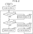
FIG. 2 is a flowchart illustrating the content of control by a control unit. -
FIG. 3 is a diagram schematically illustrating the structure of the thermal energy recovery device according to a second embodiment of the present invention. -
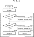
FIG. 4 is a flowchart illustrating the content of control by the control unit. -
FIG. 5 is a diagram schematically illustrating the structure of the thermal energy recovery device according to a modified example of the first embodiment of the present invention. -
FIG. 6 is a diagram schematically illustrating the structure of the thermal energy recovery device according to a modified example of the second embodiment of the present invention. - Hereinafter, embodiments for carrying out the present invention will be described with reference to the drawings.
- A thermal energy recovery device according to a first embodiment of the present invention will be described with reference to
FIG. 1 andFIG. 2 . As illustrated inFIG. 1 , the thermal energy recovery device includes anevaporator 10, anoil separator 12, anexpander 14, apower recovery machine 16, an oilsupply flow passage 18, acondenser 20, apump 22, acirculation flow passage 24 connecting theevaporator 10, theoil separator 12, theexpander 14, thecondenser 20, and thepump 22 in the mentioned order, anoil cooler 32, an oilcooling flow passage 40, an expansion valve V1, abranch flow passage 42, aswitching unit 50, and acontrol unit 60. - The
evaporator 10 is configured to allow a mixed medium including a working medium and an oil to be thermally exchanged with a heating medium, thereby evaporating at least the working medium of the mixed medium. - The
oil separator 12 is provided at a portion downstream of theevaporator 10 in thecirculation flow passage 24. Theoil separator 12 is configured to separate the oil from the mixed medium discharged from theevaporator 10. - The
expander 14 is provided at a portion downstream of theoil separator 12 in thecirculation flow passage 24. Theexpander 14 is configured to expand the gas-phase working medium discharged from theoil separator 12. In the first embodiment, a positive displacement screw expander including a rotor to be rotatably driven by expansion energy of the gas-phase working medium is utilized as theexpander 14. - The
power recovery machine 16 is connected to theexpander 14. Thepower recovery machine 16 is connected to the rotor and includes a rotation shaft rotatable with the rotor. Thepower recovery machine 16 is configured to recover power by the rotation of the rotation shaft. In the first embodiment, a generator is utilized as thepower recovery machine 16. Also, a compressor or the like may be applied as thepower recovery machine 16. - The oil
supply flow passage 18 is a flow passage configured to supply the oil separated in theoil separator 12 at least to theexpander 14. In the first embodiment, the oilsupply flow passage 18 is configured to supply the oil separated in theoil separator 12 to a bearing of theexpander 14 and a bearing of the power recovery machine (the generator in the first embodiment) 16. - The
condenser 20 is provided at a portion downstream of theexpander 14 in thecirculation flow passage 24. Thecondenser 20 is configured to allow the mixed medium discharged from theexpander 14 to be thermally exchanged with a cooling medium (cooling water or the like), thereby condensing the mixed medium. - The
pump 22 is provided at a portion downstream of the condenser 20 (at a portion between thecondenser 20 and the evaporator 10) in thecirculation flow passage 24. Thepump 22 is configured to send at a predetermined pressure the liquid-phase mixed medium discharged from thecondenser 20 to theevaporator 10. - The
oil cooler 32 is provided in the oilsupply flow passage 18 and is configured to cool the oil flowing through the oilsupply flow passage 18. - The oil
cooling flow passage 40 is branched from a portion between thepump 22 and theevaporator 10 in thecirculation flow passage 24 and is configured to pass theoil cooler 32. That is, theoil cooler 32 is configured to cool the oil flowing through the oilsupply flow passage 18 with the mixed medium flowing through the oilcooling flow passage 40. In other words, theoil cooler 32 is connected to the oilsupply flow passage 18 and the oilcooling flow passage 40 so that the oil flowing through the oilsupply flow passage 18 is cooled with the mixed medium flowing through the oilcooling flow passage 40. A downstream end of the oilcooling flow passage 40 is connected to a middle step of theexpander 14. - The expansion valve V1 is provided at a portion upstream of the
oil cooler 32 in the oilcooling flow passage 40 and is configured to adjust the opening. The expansion valve V1 is configured to depressurize the mixed medium that is pumped out from thepump 22 to flow into the oilcooling flow passage 40, thereby facilitating evaporation of the mixed medium in theoil cooler 32. In addition, the position of the downstream end of the oilcooling flow passage 40, that is, the middle step of theexpander 14 is a portion of theexpander 14, which has pressure corresponding to the pressure of the mixed medium that has passed the expansion valve V1. In a case where a multi-step expander is applied as theexpander 14, the middle step serves as a connection portion (a pipe or a reservoir) that is in the middle of expansion in the respective steps or that connects the respective steps. - The
branch flow passage 42 is branched from a portion between theoil cooler 32 and theexpander 14 in the oilcooling flow passage 40. A downstream end of thebranch flow passage 42 is connected to a portion between theexpander 14 and thecondenser 20 in thecirculation flow passage 24. - The switching
unit 50 can switch a mode where the mixed medium discharged from theoil cooler 32 flows into theexpander 14, as a first mode, to a mode where the mixed medium discharged from theoil cooler 32 flows into thebranch flow passage 42, as a second mode, and vice versa. In the first embodiment, the switchingunit 50 includes a first shut-off valve V2 and a second shut-off valve V3. The first shut-off valve V2 is provided at a portion downstream of a connection portion between the oilcooling flow passage 40 and an upstream end of thebranch flow passage 42 in the oilcooling flow passage 40. The second shut-off valve V3 is provided in thebranch flow passage 42. That is, the first shut-off valve V2 is opened and the second shut-off valve V3 is closed and thereby the switchingunit 50 is brought into the first mode. The first shut-off valve V2 is closed and the second shut-off valve V3 is opened and thereby the switchingunit 50 is brought into the second mode. - The
control unit 60 is configured to control the expansion valve V1 and the switchingunit 50. In the first embodiment, thecontrol unit 60 includes an expansionvalve adjustment portion 61, agasification determination portion 62, and a switchingunit adjustment portion 63. - The expansion
valve adjustment portion 61 is configured to adjust the opening of the expansion valve 1 so that the temperature of a portion between theoil cooler 32 and theexpander 14 in the oil supply flow passage 18 (the temperature of the oil flowing into the expander 14) is maintained at a level below a reference temperature, i.e., so that the viscosity of the oil supplied to theexpander 14 is maintained at a level equal to or greater than a required value. Also, the temperature of a portion between theoil cooler 32 and theexpander 14 in the oilsupply flow passage 18 is detected by atemperature sensor 71 provided in the portion. - The
gasification determination portion 62 is configured to determine whether the mixed medium discharged from theoil cooler 32 is in a gas phase. In the first embodiment, thegasification determination portion 62 is configured to calculate the degree of superheat of the mixed medium discharged from theoil cooler 32. In addition, when the degree of super heat is greater than a set value, thegasification determination portion 62 determines that the mixed medium is in a gas phase. Meanwhile, when the degree of superheat is equal to or smaller than the set value, thegasification determination portion 62 determines that the mixed medium contains a liquid phase. In addition, the degree of superheat of the mixed medium discharged from theoil cooler 32 is calculated based on detection values by apressure sensor 72 and atemperature sensor 73 that are provided at a portion between theoil cooler 32 and the first shut-off valve V2 in the oilcooling flow passage 40 or at a portion upstream of the second shut-off valve V3 in thebranch flow passage 42. - The switching
unit adjustment portion 63 is configured to switch theswitching unit 50 to the first mode (open the first shut-off valve V2 and close the second shut-off valve V3) when thegasification determination portion 62 has determined that the entire mixed medium discharged from theoil cooler 32 is in a gas phase (in the first embodiment, when the degree of superheat of the mixed medium discharged from theoil cooler 32 is greater than the set value). On the other hand, the switchingunit adjustment portion 63 is configured to switch theswitching unit 50 to the second mode (close the first shut-off valve V2 and open the second shut-off valve V3) when thegasification determination portion 62 has determined that the mixed medium discharged from theoil cooler 32 contains a liquid phase. - Herein, the concrete content of control by the
control unit 60 will be described with reference toFIG. 2 . - First, the switching
unit adjustment portion 63 of thecontrol unit 60 closes the first shut-off valve V2 and opens the second shut-off valve V3 (step ST11). Next, the expansionvalve adjustment portion 61 of thecontrol unit 60 determines whether a detection value To by thetemperature sensor 71 is below a reference temperature T1 (step ST12). As a result, when the detection value To is equal to or greater than the reference temperature T1, that is, when the viscosity of the oil supplied to theexpander 14 is below the required value, the expansionvalve adjustment portion 61 increase the opening of the expansion valve V1 to increase the volume of the oil to be cooled in the oil cooler 32 (step ST13). - Also, when the detection value To is below the reference temperature T1 in step ST12 (when YES in step ST12) or after step ST13, the
gasification determination portion 62 of thecontrol unit 60 determines whether the degree of superheat S calculated based on a detection value by thepressure sensor 72 and a detection value by thetemperature sensor 73 is greater than a set value α (step ST14). As a result, when the degree of superheat S is greater than the set value a, that is, when the entire mixed medium discharged from theoil cooler 32 is in a gas phase and the mixed medium is supplied into theexpander 14 whereby power can be recovered in thepower recovery machine 16, the switchingunit adjustment portion 63 of thecontrol unit 60 opens the first shut-off valve V2 and closes the second shut-off valve V3 (brings the switchingunit 50 to the first mode) (step ST15), and the processing returns to step ST12. Meanwhile, when the degree of superheat S is equal to or smaller than the set value a, that is, when the mixed medium discharged from theoil cooler 32 may contain a liquid phase, the expansionvalve adjustment portion 61 decreases the opening of the expansion valve V1 to decrease the flow volume of the mixed medium into the oil cooler 32 (step ST16). Then, at the same time as step ST16 or after step ST16, the switchingunit adjustment portion 63 closes the first shut-off valve V2 and opens the second shut-off valve V3 (brings the switchingunit 50 to the second mode) (step ST17), and the processing returns to step ST12. - As described above, in the thermal energy recovery device according to the first embodiment, the mixed medium pumped out from the
pump 22 passes the expansion valve V1 and thereby is depressurized. Therefore, the mixed medium easily evaporates in theoil cooler 32, and the evaporation of the mixed medium in theoil cooler 32 allows the oil to be effectively cooled. Then, the mixed medium evaporated in theoil cooler 32 is supplied through the oilcooling flow passage 40 to the middle step of theexpander 14. Thus, energy supplied into the expander 14 (power to be recovered in the power recovery machine 16) increases. In addition, a heat exchange including the evaporation phenomenon of the mixed medium is performed in theoil cooler 32. Consequently, theoil cooler 32 can be downsized compared with a case where only a sensible heat exchange of the oil with the mixed medium is performed in theoil cooler 32. - Also, since the
control unit 60 includes the switchingunit adjustment portion 63, the gas-phase mixed medium flows into theexpander 14, and thereby power can be effectively recovered in thepower recovery machine 16 and the liquid-phase mixed medium can be inhibited from flowing into theexpander 14. - Next, the thermal energy recovery device according to a second embodiment of the present invention will be described with reference to
FIG. 3 . In addition, only differences from the first embodiment will be described in the second embodiment, and descriptions of the same structures, functions, and effects as those of the first embodiment will be omitted in the second embodiment. - In the second embodiment, in place of the switching
unit 50, a gas-liquid separator 44 is provided at a portion between theoil cooler 32 and theexpander 14 in the oilcooling flow passage 40. The upstream end of thebranch flow passage 42 is connected to, for example, a lower portion of the gas-liquid separator 44. A shut-off valve V4 is provided in thebranch flow passage 42. Afluid level sensor 74 is provided at the gas-liquid separator 44. Further, a check valve 45 is provided at a portion downstream of the gas-liquid separator 44 in the oilcooling flow passage 40. The check valve 45 is configured to allow the mixed medium to pass from the gas-liquid separator 44 to theexpander 14 and to prevent the mixed medium from passing from theexpander 14 to the gas-liquid separator 44. - Furthermore, in the second embodiment, the
control unit 60 includes, in place of the switchingunit adjustment portion 63, a shut-offvalve adjustment portion 64 configured to regulate opening/closing of the shut-off valve V4. When thegasification determination portion 62 has determined that the entire mixed medium discharged from the gas-liquid separator 44 into the oilcooling flow passage 40 is in a gas phase (in the second embodiment, when the degree of superheat of the mixed medium discharged from the gas-liquid separator 44 into the oilcooling flow passage 40 is greater than a set value), the shut-offvalve adjustment portion 64 closes the shut-off valve V4. In addition, when thegasification determination portion 62 has determined that the mixed medium discharged from the gas-liquid separator 44 into the oilcooling flow passage 40 contains a liquid phase, the shut-offvalve adjustment portion 64 closes the shut-off valve V4. - Specifically, the content of control by the
control unit 60 according to the second embodiment will be described with reference toFIG. 4 . - First, the shut-off
valve adjustment portion 64 of thecontrol unit 60 opens the shut-off valve V4 (step ST21). Also, steps ST22 to ST24 are the same as steps ST12 to ST14 and therefore the descriptions will be omitted. - In step ST24, when the degree of superheat S is greater than a set value α (when YES in step ST24), the shut-off
valve adjustment portion 64 closes the shut-off valve V4 (step ST25), and the processing returns to step ST22. Meanwhile, in step ST24, when the degree of superheat S is equal to or smaller than the set value α (when NO in step ST24), the expansionvalve adjustment portion 61 decreases the opening of the expansion valve V1 (step ST26). Then, at the same time as step ST26 or after step ST26, the shut-offvalve adjustment portion 64 opens the shut-off valve V4 (step ST27), and the processing returns to step ST22. - As described above, the thermal energy recovery device according to the second embodiment includes the gas-
liquid separator 44 and he branchflow passage 42. Therefore, even when the mixed medium is discharged in a gas-liquid two-phase from theoil cooler 32, the mixed medium is separated into a gas phase and a liquid phase in the gas-liquid separator 44 and only the gas-phase mixed medium is guided through the oilcooling flow passage 40 to theexpander 14. Consequently, the gas-phase mixed medium flows into theexpander 14, and thereby power can be effectively recovered in thepower recovery machine 16 and the liquid-phase mixed medium can be inhibited from flowing into theexpander 14. - Further, the check valve V5 is provided at a portion downstream of the gas-
liquid separator 44 in the oilcooling flow passage 40; therefore, a backward flow of the mixed medium from theexpander 14 to the gas-liquid separator 44 is prevented, that is, a reduction in power recovery in thepower recovery machine 16 is prevented. - Furthermore, the thermal energy recover device according to the second embodiment includes the shut-off valve V4 provided in the
branch flow passage 42 and the shut-offvalve adjustment portion 64. Therefore, the gas-phase mixed medium is inhibited from flowing out from the gas-liquid separator 44 to the branch flow passage 42 (a loss in recoverable power in the power recovery machine 16), and in addition, the liquid-phase mixed medium is inhibited from being excessively stored in the gas-liquid separator 44. - Here, in the second embodiment, when a detection value by the
fluid level sensor 74 is below a set value, the shut-offvalve adjustment portion 64 may close the shut-off valve V4. When a detection value by thefluid level sensor 74 is equal to or greater than the set value, the shut-offvalve adjustment portion 64 may open the shut-off valve V4. In such a case, steps ST21, ST25, and ST27 are omitted and thecontrol unit 60 performs operations of steps ST22 to ST24 and step ST26 in parallel with an operation by the shut-offvalve adjustment portion 64. - Also, the embodiments described here are to be considered in all respects as illustrative and as non-restrictive. The scope of the present invention is indicated not by the descriptions of the foregoing embodiments but by the claims, and the scope of the present invention may include all changes within the meaning equivalent to the claims and within the claims.
- For example, as illustrated in
FIG. 5 andFIG. 6 , in each embodiment, aheater 26 may be provided at a portion between theoil cooler 32 and theexpander 14 in the oilcooling flow passage 40 and at a portion between theexpander 14 and thecondenser 20 in thecirculation flow passage 24. Theheater 26 is configured to heat the mixed medium discharged from theoil cooler 32 with the mixed medium discharged from theexpander 14. Thus, evaporation of the mixed medium discharged from theoil cooler 32 is facilitated. Further, in the second embodiment, theheater 26 is preferably provided at a portion between the gas-liquid separator 44 and theexpander 14 in the oilcooling flow passage 40. - Furthermore, a
portion 41 between theoil cooler 32 and theexpander 14 in the oilcooling flow passage 40 may be connected to thepower recovery machine 16 so that the mixed medium discharged from theoil cooler 32 is heated by thepower recovery machine 16. With such a configuration, the mixed medium discharged from theoil cooler 32 recovers exhaust heat of thepower recovery machine 16; therefore, power to be recovered in thepower recovery machine 16 increases. Further, in the second embodiment, theportion 41 is preferably selected from a portion downstream of the gas-liquid separator 44 in the oilcooling flow passage 40. Moreover, theportion 41 may be provided in parallel with or in series with a portion connected to theheater 26 in the oilcooling flow passage 40. Further, at least one of theheater 26 and theportion 41 may be provided at a portion upstream of theoil cooler 32 in the oilcooling flow passage 40. - Furthermore, in the first embodiment, a sensor is provided at a portion between the
oil cooler 32 and the first shut-off valve V2 in the oilcooling flow passage 40, and the sensor may be configured to detect whether the mixed medium flowing through the portion contains a liquid phase. Thus, thegasification determination portion 62 may determine based on a detection result of the sensor whether the mixed medium in the portion is in a gas phase. Likewise, in the second embodiment, the above sensor is provided at a portion between the gas-liquid separator 44 and theexpander 14 in the oilcooling flow passage 40, and thegasification determination portion 62 may determine based on a detection result of the sensor whether the mixed medium in the portion is in a gas phase. - A thermal energy recovery device includes an evaporator, an oil separator, an expander, a power recovery machine, an oil supply flow passage, a condenser, a pump, a circulation flow passage, an oil cooler, an oil cooling flow passage, an expansion valve provided at a portion upstream of the oil cooler in the oil cooling flow passage, and an expansion valve adjustment portion configured to adjust the opening of the expansion valve. The oil cooler allows an oil flowing through the oil supply flow passage to be thermally exchanged with a mixed medium flowing through the oil cooling flow passage and evaporates at least a portion of the mixed medium, and a downstream end of the oil cooling flow passage is connected to a middle step of the evaporator.
Claims (7)
- A thermal energy recovery device comprising:an evaporator configured to evaporate a mixed medium including a working medium and an oil;an oil separator configured to separate the oil from the mixed medium discharged from the evaporator;an expander configured to expand the working medium discharged from the oil separator;a power recovery machine connected to the expander;an oil supply flow passage configured to supply the oil, discharged from the oil separator, to the expander;a condenser configured to condense the mixed medium discharged from the expander;a pump configured to send the mixed medium, discharged from the condenser, to the evaporator;a circulation flow passage connecting the evaporator, the oil separator, the expander, the condenser, and the pump in the mentioned order;an oil cooler configured to cool the oil flowing through the oil supply flow passage;an oil cooling flow passage branched from a portion between the pump and the evaporator in the circulation flow passage and configured to pass the oil cooler;an expansion valve provided at a portion upstream of the oil cooler in the oil cooling flow passage and configured to adjust the opening; andan expansion valve adjustment portion configured to adjust the opening of the expansion valve so that the temperature of the oil flowing through a portion between the oil cooler and the expander in the oil supply flow passage is maintained at a value below a reference temperature, whereinthe oil cooler allows the oil flowing through the oil supply flow passage to be thermally exchanged with the mixed medium flowing through the oil cooling flow passage and evaporates at least a portion of the mixed medium, anda downstream end of the oil cooling flow passage is connected to a middle step of the expander.
- The thermal energy recovery device according to claim 1, further comprising:a branch flow passage branched from a portion between the oil cooler and the expander in the oil cooling flow passage and connected to a portion between the expander and the condenser in the circulation flow passage;a switching unit configured to switch a mode where the mixed medium discharged from the oil cooler flows into the expander, as a first mode, to a mode where the mixed medium discharged from the oil cooler flows into the branch flow passage, as a second mode, and vice versa; anda switching unit adjustment portion configured to switch the switching unit to the first mode when the mixed medium discharged from the oil cooler is determined to be in a gas phase, the switching unit adjustment portion being configured to switch the switching unit to the second mode when the mixed medium flowing through a portion between the oil cooler and the switching unit in the oil cooling flow passage is determined to contain a liquid phase.
- The thermal energy recovery device according to claim 1, further comprising:a gas-liquid separator provided at a portion between the oil cooler and the expander in the oil cooling flow passage; anda branch flow passage configured to guide, to the condenser, the liquid-phase mixed medium into which the mixed medium is separated in the gas-liquid separator.
- The thermal energy recovery device according to claim 3, further comprising:a check valve provided between the gas-liquid separator and the expander in the oil cooling flow passage, the check valve being configured to allow the mixed medium to pass from the gas-liquid separator to the expander and to prevent the mixed medium from passing from the expander to the gas-liquid separator.
- The thermal energy recovery device according to claim 3 or 4, further comprising:a shut-off valve provided in the branch flow passage;a shut-off valve adjustment portion configured to close the shut-off valve when the mixed medium flowing through a portion between the gas-liquid separator and the expander in the oil cooling flow passage is determined to be in a gas phase, the shut-off valve adjustment portion being configured to close the shut-off valve when the mixed medium flowing through a portion between the gas-liquid separator and the expander in the oil cooling flow passage is determined to contain a liquid phase.
- The thermal energy recovery device according to any one of claims 1 to 5, further comprising:a heater provided at a portion between the oil cooler and the expander in the oil cooling flow passage and at a portion between the expander and the condenser in the circulation flow passage and configured to heat the mixed medium discharged from the oil cooler with the mixed medium discharged from the expander.
- The thermal energy recovery device according to any one of claims 1 to 6, wherein a portion between the oil cooler and the expander in the oil cooling flow passage is connected to the power recovery machine so that the mixed medium discharged from the oil cooler is heated by the power recovery machine.
Applications Claiming Priority (1)
| Application Number | Priority Date | Filing Date | Title |
|---|---|---|---|
| JP2017232463A JP6763848B2 (en) | 2017-12-04 | 2017-12-04 | Thermal energy recovery device |
Publications (2)
| Publication Number | Publication Date |
|---|---|
| EP3492714A1 true EP3492714A1 (en) | 2019-06-05 |
| EP3492714B1 EP3492714B1 (en) | 2020-12-09 |
Family
ID=63965224
Family Applications (1)
| Application Number | Title | Priority Date | Filing Date |
|---|---|---|---|
| EP18201705.3A Not-in-force EP3492714B1 (en) | 2017-12-04 | 2018-10-22 | Thermal energy recovery device |
Country Status (4)
| Country | Link |
|---|---|
| EP (1) | EP3492714B1 (en) |
| JP (1) | JP6763848B2 (en) |
| KR (1) | KR102090980B1 (en) |
| CN (1) | CN109869207B (en) |
Cited By (2)
| Publication number | Priority date | Publication date | Assignee | Title |
|---|---|---|---|---|
| WO2024100669A1 (en) * | 2022-11-10 | 2024-05-16 | Technion Research & Development Foundation Limited | Thermal energy storage system |
| BE1031272B1 (en) * | 2023-01-19 | 2024-08-19 | Atlas Copco Airpower Nv | Method and design for power generation |
Citations (8)
| Publication number | Priority date | Publication date | Assignee | Title |
|---|---|---|---|---|
| US20100034684A1 (en) * | 2008-08-07 | 2010-02-11 | General Electric Company | Method for lubricating screw expanders and system for controlling lubrication |
| JP2012097725A (en) | 2010-10-07 | 2012-05-24 | Kobe Steel Ltd | Power generation system |
| US20120237382A1 (en) * | 2009-12-14 | 2012-09-20 | Kabushiki Kaisha Kobe Seiko Sho (Kobe Steel, Ltd.) | Screw expander system |
| JP2012246902A (en) * | 2011-05-31 | 2012-12-13 | Kobe Steel Ltd | Pump system and binary electrical generator |
| JP2014062542A (en) * | 2012-08-29 | 2014-04-10 | Kobe Steel Ltd | Power generating apparatus and control method for power generating apparatus |
| WO2014117156A1 (en) * | 2013-01-28 | 2014-07-31 | Eaton Corporation | Organic rankine cycle system with lubrication circuit |
| JP2014231820A (en) * | 2013-05-30 | 2014-12-11 | 株式会社神戸製鋼所 | Binary driving device |
| JP2016014329A (en) * | 2014-07-01 | 2016-01-28 | 株式会社神戸製鋼所 | Thermal energy recovery device |
Family Cites Families (9)
| Publication number | Priority date | Publication date | Assignee | Title |
|---|---|---|---|---|
| JP4427364B2 (en) * | 2004-03-19 | 2010-03-03 | 株式会社荏原製作所 | Power generator |
| JP4659503B2 (en) * | 2005-03-31 | 2011-03-30 | 株式会社荏原製作所 | Power generation device and lubricating oil recovery method |
| GB0511864D0 (en) * | 2005-06-10 | 2005-07-20 | Univ City | Expander lubrication in vapour power systems |
| JP4977638B2 (en) * | 2008-02-14 | 2012-07-18 | サンデン株式会社 | Waste heat utilization equipment |
| EP2514933B1 (en) * | 2011-04-19 | 2017-03-15 | Orcan Energy AG | High pressure separation of liquid lubricant to lubricate volumetric expansion machines |
| EP2520771B1 (en) * | 2011-05-03 | 2016-08-10 | Orcan Energy AG | Method and device for quick oil heating for oil-lubricated expansion machines |
| JP5597597B2 (en) * | 2011-06-09 | 2014-10-01 | 株式会社神戸製鋼所 | Power generator |
| JP2014163608A (en) * | 2013-02-26 | 2014-09-08 | Kobe Steel Ltd | Binary power generation device and operation method of binary power generation device |
| CN105673108A (en) * | 2016-04-01 | 2016-06-15 | 上海开山能源装备有限公司 | Oil injection ORC expander system |
-
2017
- 2017-12-04 JP JP2017232463A patent/JP6763848B2/en not_active Expired - Fee Related
-
2018
- 2018-10-22 EP EP18201705.3A patent/EP3492714B1/en not_active Not-in-force
- 2018-11-26 KR KR1020180147003A patent/KR102090980B1/en not_active Expired - Fee Related
- 2018-12-04 CN CN201811474090.2A patent/CN109869207B/en not_active Expired - Fee Related
Patent Citations (8)
| Publication number | Priority date | Publication date | Assignee | Title |
|---|---|---|---|---|
| US20100034684A1 (en) * | 2008-08-07 | 2010-02-11 | General Electric Company | Method for lubricating screw expanders and system for controlling lubrication |
| US20120237382A1 (en) * | 2009-12-14 | 2012-09-20 | Kabushiki Kaisha Kobe Seiko Sho (Kobe Steel, Ltd.) | Screw expander system |
| JP2012097725A (en) | 2010-10-07 | 2012-05-24 | Kobe Steel Ltd | Power generation system |
| JP2012246902A (en) * | 2011-05-31 | 2012-12-13 | Kobe Steel Ltd | Pump system and binary electrical generator |
| JP2014062542A (en) * | 2012-08-29 | 2014-04-10 | Kobe Steel Ltd | Power generating apparatus and control method for power generating apparatus |
| WO2014117156A1 (en) * | 2013-01-28 | 2014-07-31 | Eaton Corporation | Organic rankine cycle system with lubrication circuit |
| JP2014231820A (en) * | 2013-05-30 | 2014-12-11 | 株式会社神戸製鋼所 | Binary driving device |
| JP2016014329A (en) * | 2014-07-01 | 2016-01-28 | 株式会社神戸製鋼所 | Thermal energy recovery device |
Cited By (2)
| Publication number | Priority date | Publication date | Assignee | Title |
|---|---|---|---|---|
| WO2024100669A1 (en) * | 2022-11-10 | 2024-05-16 | Technion Research & Development Foundation Limited | Thermal energy storage system |
| BE1031272B1 (en) * | 2023-01-19 | 2024-08-19 | Atlas Copco Airpower Nv | Method and design for power generation |
Also Published As
| Publication number | Publication date |
|---|---|
| KR20190065940A (en) | 2019-06-12 |
| CN109869207B (en) | 2021-10-15 |
| JP2019100263A (en) | 2019-06-24 |
| EP3492714B1 (en) | 2020-12-09 |
| CN109869207A (en) | 2019-06-11 |
| JP6763848B2 (en) | 2020-09-30 |
| KR102090980B1 (en) | 2020-03-19 |
Similar Documents
| Publication | Publication Date | Title |
|---|---|---|
| KR100856991B1 (en) | Refrigerating air conditioner, operation control method of refrigerating air conditioner, and refrigerant quantity control method of refrigerating air conditioner | |
| JP6595205B2 (en) | Refrigeration cycle equipment | |
| JP4269323B2 (en) | Heat pump water heater | |
| CN109323477A (en) | A transcritical CO2 heat pump system based on a precooler and a control method for a two-way valve in the water circuit | |
| JP5278451B2 (en) | Refrigeration cycle apparatus and hot water heater using the same | |
| US20140260379A1 (en) | Expansion valve control for heat transfer system | |
| WO2014091548A1 (en) | Air conditioning hot water supply composite system | |
| CN102032698A (en) | Refrigeration cycle apparatus and hot water heater | |
| JP2010112655A (en) | Refrigeration equipment | |
| WO2007104970A2 (en) | Working fluid control in non-aqueous vapour power systems | |
| US20140260380A1 (en) | Compressor control for heat transfer system | |
| EP3492714B1 (en) | Thermal energy recovery device | |
| JP2008298407A (en) | Multi-source heat pump steam / hot water generator | |
| JP6188629B2 (en) | Binary power generator operation method | |
| JPWO2017081781A1 (en) | Waste heat recovery heat pump device | |
| JP2009052880A (en) | Heat pump water heater | |
| JP2013117330A (en) | Refrigeration cycle device and hot water producing apparatus comprising the same | |
| JP2015152194A (en) | Refrigeration cycle equipment | |
| KR101269843B1 (en) | Refrigerant condensing temperature adjustable heat pump system based on ambient temperature and evaporating temperature | |
| JP6757631B2 (en) | Binary power generation system | |
| JP2008121977A (en) | Heat pump water heater | |
| KR101639535B1 (en) | Thermal energy recovery device | |
| CN109812308A (en) | heat recovery system | |
| WO2015136595A1 (en) | Heat pump system | |
| JP6190330B2 (en) | Thermal energy recovery device |
Legal Events
| Date | Code | Title | Description |
|---|---|---|---|
| PUAI | Public reference made under article 153(3) epc to a published international application that has entered the european phase |
Free format text: ORIGINAL CODE: 0009012 |
|
| STAA | Information on the status of an ep patent application or granted ep patent |
Free format text: STATUS: REQUEST FOR EXAMINATION WAS MADE |
|
| 17P | Request for examination filed |
Effective date: 20181022 |
|
| AK | Designated contracting states |
Kind code of ref document: A1 Designated state(s): AL AT BE BG CH CY CZ DE DK EE ES FI FR GB GR HR HU IE IS IT LI LT LU LV MC MK MT NL NO PL PT RO RS SE SI SK SM TR |
|
| AX | Request for extension of the european patent |
Extension state: BA ME |
|
| GRAP | Despatch of communication of intention to grant a patent |
Free format text: ORIGINAL CODE: EPIDOSNIGR1 |
|
| STAA | Information on the status of an ep patent application or granted ep patent |
Free format text: STATUS: GRANT OF PATENT IS INTENDED |
|
| INTG | Intention to grant announced |
Effective date: 20200519 |
|
| GRAJ | Information related to disapproval of communication of intention to grant by the applicant or resumption of examination proceedings by the epo deleted |
Free format text: ORIGINAL CODE: EPIDOSDIGR1 |
|
| STAA | Information on the status of an ep patent application or granted ep patent |
Free format text: STATUS: REQUEST FOR EXAMINATION WAS MADE |
|
| GRAR | Information related to intention to grant a patent recorded |
Free format text: ORIGINAL CODE: EPIDOSNIGR71 |
|
| GRAS | Grant fee paid |
Free format text: ORIGINAL CODE: EPIDOSNIGR3 |
|
| STAA | Information on the status of an ep patent application or granted ep patent |
Free format text: STATUS: GRANT OF PATENT IS INTENDED |
|
| INTC | Intention to grant announced (deleted) | ||
| GRAA | (expected) grant |
Free format text: ORIGINAL CODE: 0009210 |
|
| STAA | Information on the status of an ep patent application or granted ep patent |
Free format text: STATUS: THE PATENT HAS BEEN GRANTED |
|
| INTG | Intention to grant announced |
Effective date: 20201019 |
|
| AK | Designated contracting states |
Kind code of ref document: B1 Designated state(s): AL AT BE BG CH CY CZ DE DK EE ES FI FR GB GR HR HU IE IS IT LI LT LU LV MC MK MT NL NO PL PT RO RS SE SI SK SM TR |
|
| REG | Reference to a national code |
Ref country code: GB Ref legal event code: FG4D |
|
| REG | Reference to a national code |
Ref country code: AT Ref legal event code: REF Ref document number: 1343666 Country of ref document: AT Kind code of ref document: T Effective date: 20201215 Ref country code: CH Ref legal event code: EP |
|
| REG | Reference to a national code |
Ref country code: DE Ref legal event code: R096 Ref document number: 602018010602 Country of ref document: DE |
|
| REG | Reference to a national code |
Ref country code: IE Ref legal event code: FG4D |
|
| PG25 | Lapsed in a contracting state [announced via postgrant information from national office to epo] |
Ref country code: RS Free format text: LAPSE BECAUSE OF FAILURE TO SUBMIT A TRANSLATION OF THE DESCRIPTION OR TO PAY THE FEE WITHIN THE PRESCRIBED TIME-LIMIT Effective date: 20201209 Ref country code: FI Free format text: LAPSE BECAUSE OF FAILURE TO SUBMIT A TRANSLATION OF THE DESCRIPTION OR TO PAY THE FEE WITHIN THE PRESCRIBED TIME-LIMIT Effective date: 20201209 Ref country code: GR Free format text: LAPSE BECAUSE OF FAILURE TO SUBMIT A TRANSLATION OF THE DESCRIPTION OR TO PAY THE FEE WITHIN THE PRESCRIBED TIME-LIMIT Effective date: 20210310 Ref country code: NO Free format text: LAPSE BECAUSE OF FAILURE TO SUBMIT A TRANSLATION OF THE DESCRIPTION OR TO PAY THE FEE WITHIN THE PRESCRIBED TIME-LIMIT Effective date: 20210309 |
|
| REG | Reference to a national code |
Ref country code: AT Ref legal event code: MK05 Ref document number: 1343666 Country of ref document: AT Kind code of ref document: T Effective date: 20201209 |
|
| PG25 | Lapsed in a contracting state [announced via postgrant information from national office to epo] |
Ref country code: BG Free format text: LAPSE BECAUSE OF FAILURE TO SUBMIT A TRANSLATION OF THE DESCRIPTION OR TO PAY THE FEE WITHIN THE PRESCRIBED TIME-LIMIT Effective date: 20210309 Ref country code: LV Free format text: LAPSE BECAUSE OF FAILURE TO SUBMIT A TRANSLATION OF THE DESCRIPTION OR TO PAY THE FEE WITHIN THE PRESCRIBED TIME-LIMIT Effective date: 20201209 Ref country code: SE Free format text: LAPSE BECAUSE OF FAILURE TO SUBMIT A TRANSLATION OF THE DESCRIPTION OR TO PAY THE FEE WITHIN THE PRESCRIBED TIME-LIMIT Effective date: 20201209 |
|
| REG | Reference to a national code |
Ref country code: NL Ref legal event code: MP Effective date: 20201209 |
|
| PG25 | Lapsed in a contracting state [announced via postgrant information from national office to epo] |
Ref country code: NL Free format text: LAPSE BECAUSE OF FAILURE TO SUBMIT A TRANSLATION OF THE DESCRIPTION OR TO PAY THE FEE WITHIN THE PRESCRIBED TIME-LIMIT Effective date: 20201209 Ref country code: HR Free format text: LAPSE BECAUSE OF FAILURE TO SUBMIT A TRANSLATION OF THE DESCRIPTION OR TO PAY THE FEE WITHIN THE PRESCRIBED TIME-LIMIT Effective date: 20201209 |
|
| REG | Reference to a national code |
Ref country code: LT Ref legal event code: MG9D |
|
| PG25 | Lapsed in a contracting state [announced via postgrant information from national office to epo] |
Ref country code: SM Free format text: LAPSE BECAUSE OF FAILURE TO SUBMIT A TRANSLATION OF THE DESCRIPTION OR TO PAY THE FEE WITHIN THE PRESCRIBED TIME-LIMIT Effective date: 20201209 Ref country code: SK Free format text: LAPSE BECAUSE OF FAILURE TO SUBMIT A TRANSLATION OF THE DESCRIPTION OR TO PAY THE FEE WITHIN THE PRESCRIBED TIME-LIMIT Effective date: 20201209 Ref country code: EE Free format text: LAPSE BECAUSE OF FAILURE TO SUBMIT A TRANSLATION OF THE DESCRIPTION OR TO PAY THE FEE WITHIN THE PRESCRIBED TIME-LIMIT Effective date: 20201209 Ref country code: CZ Free format text: LAPSE BECAUSE OF FAILURE TO SUBMIT A TRANSLATION OF THE DESCRIPTION OR TO PAY THE FEE WITHIN THE PRESCRIBED TIME-LIMIT Effective date: 20201209 Ref country code: RO Free format text: LAPSE BECAUSE OF FAILURE TO SUBMIT A TRANSLATION OF THE DESCRIPTION OR TO PAY THE FEE WITHIN THE PRESCRIBED TIME-LIMIT Effective date: 20201209 Ref country code: PT Free format text: LAPSE BECAUSE OF FAILURE TO SUBMIT A TRANSLATION OF THE DESCRIPTION OR TO PAY THE FEE WITHIN THE PRESCRIBED TIME-LIMIT Effective date: 20210409 Ref country code: LT Free format text: LAPSE BECAUSE OF FAILURE TO SUBMIT A TRANSLATION OF THE DESCRIPTION OR TO PAY THE FEE WITHIN THE PRESCRIBED TIME-LIMIT Effective date: 20201209 |
|
| PG25 | Lapsed in a contracting state [announced via postgrant information from national office to epo] |
Ref country code: AT Free format text: LAPSE BECAUSE OF FAILURE TO SUBMIT A TRANSLATION OF THE DESCRIPTION OR TO PAY THE FEE WITHIN THE PRESCRIBED TIME-LIMIT Effective date: 20201209 Ref country code: PL Free format text: LAPSE BECAUSE OF FAILURE TO SUBMIT A TRANSLATION OF THE DESCRIPTION OR TO PAY THE FEE WITHIN THE PRESCRIBED TIME-LIMIT Effective date: 20201209 |
|
| REG | Reference to a national code |
Ref country code: DE Ref legal event code: R097 Ref document number: 602018010602 Country of ref document: DE |
|
| PG25 | Lapsed in a contracting state [announced via postgrant information from national office to epo] |
Ref country code: IS Free format text: LAPSE BECAUSE OF FAILURE TO SUBMIT A TRANSLATION OF THE DESCRIPTION OR TO PAY THE FEE WITHIN THE PRESCRIBED TIME-LIMIT Effective date: 20210409 |
|
| PLBE | No opposition filed within time limit |
Free format text: ORIGINAL CODE: 0009261 |
|
| STAA | Information on the status of an ep patent application or granted ep patent |
Free format text: STATUS: NO OPPOSITION FILED WITHIN TIME LIMIT |
|
| PG25 | Lapsed in a contracting state [announced via postgrant information from national office to epo] |
Ref country code: AL Free format text: LAPSE BECAUSE OF FAILURE TO SUBMIT A TRANSLATION OF THE DESCRIPTION OR TO PAY THE FEE WITHIN THE PRESCRIBED TIME-LIMIT Effective date: 20201209 Ref country code: IT Free format text: LAPSE BECAUSE OF FAILURE TO SUBMIT A TRANSLATION OF THE DESCRIPTION OR TO PAY THE FEE WITHIN THE PRESCRIBED TIME-LIMIT Effective date: 20201209 |
|
| 26N | No opposition filed |
Effective date: 20210910 |
|
| PG25 | Lapsed in a contracting state [announced via postgrant information from national office to epo] |
Ref country code: SI Free format text: LAPSE BECAUSE OF FAILURE TO SUBMIT A TRANSLATION OF THE DESCRIPTION OR TO PAY THE FEE WITHIN THE PRESCRIBED TIME-LIMIT Effective date: 20201209 Ref country code: DK Free format text: LAPSE BECAUSE OF FAILURE TO SUBMIT A TRANSLATION OF THE DESCRIPTION OR TO PAY THE FEE WITHIN THE PRESCRIBED TIME-LIMIT Effective date: 20201209 |
|
| PG25 | Lapsed in a contracting state [announced via postgrant information from national office to epo] |
Ref country code: ES Free format text: LAPSE BECAUSE OF FAILURE TO SUBMIT A TRANSLATION OF THE DESCRIPTION OR TO PAY THE FEE WITHIN THE PRESCRIBED TIME-LIMIT Effective date: 20201209 |
|
| PGFP | Annual fee paid to national office [announced via postgrant information from national office to epo] |
Ref country code: DE Payment date: 20210914 Year of fee payment: 4 |
|
| REG | Reference to a national code |
Ref country code: CH Ref legal event code: PL |
|
| PG25 | Lapsed in a contracting state [announced via postgrant information from national office to epo] |
Ref country code: IS Free format text: LAPSE BECAUSE OF FAILURE TO SUBMIT A TRANSLATION OF THE DESCRIPTION OR TO PAY THE FEE WITHIN THE PRESCRIBED TIME-LIMIT Effective date: 20210409 |
|
| REG | Reference to a national code |
Ref country code: BE Ref legal event code: MM Effective date: 20211031 |
|
| PG25 | Lapsed in a contracting state [announced via postgrant information from national office to epo] |
Ref country code: MC Free format text: LAPSE BECAUSE OF FAILURE TO SUBMIT A TRANSLATION OF THE DESCRIPTION OR TO PAY THE FEE WITHIN THE PRESCRIBED TIME-LIMIT Effective date: 20201209 |
|
| PG25 | Lapsed in a contracting state [announced via postgrant information from national office to epo] |
Ref country code: LU Free format text: LAPSE BECAUSE OF NON-PAYMENT OF DUE FEES Effective date: 20211022 Ref country code: BE Free format text: LAPSE BECAUSE OF NON-PAYMENT OF DUE FEES Effective date: 20211031 |
|
| PG25 | Lapsed in a contracting state [announced via postgrant information from national office to epo] |
Ref country code: LI Free format text: LAPSE BECAUSE OF NON-PAYMENT OF DUE FEES Effective date: 20211031 Ref country code: CH Free format text: LAPSE BECAUSE OF NON-PAYMENT OF DUE FEES Effective date: 20211031 |
|
| PG25 | Lapsed in a contracting state [announced via postgrant information from national office to epo] |
Ref country code: FR Free format text: LAPSE BECAUSE OF NON-PAYMENT OF DUE FEES Effective date: 20211031 |
|
| PG25 | Lapsed in a contracting state [announced via postgrant information from national office to epo] |
Ref country code: IE Free format text: LAPSE BECAUSE OF NON-PAYMENT OF DUE FEES Effective date: 20211022 |
|
| REG | Reference to a national code |
Ref country code: DE Ref legal event code: R119 Ref document number: 602018010602 Country of ref document: DE |
|
| GBPC | Gb: european patent ceased through non-payment of renewal fee |
Effective date: 20221022 |
|
| PG25 | Lapsed in a contracting state [announced via postgrant information from national office to epo] |
Ref country code: CY Free format text: LAPSE BECAUSE OF FAILURE TO SUBMIT A TRANSLATION OF THE DESCRIPTION OR TO PAY THE FEE WITHIN THE PRESCRIBED TIME-LIMIT Effective date: 20201209 |
|
| PG25 | Lapsed in a contracting state [announced via postgrant information from national office to epo] |
Ref country code: HU Free format text: LAPSE BECAUSE OF FAILURE TO SUBMIT A TRANSLATION OF THE DESCRIPTION OR TO PAY THE FEE WITHIN THE PRESCRIBED TIME-LIMIT; INVALID AB INITIO Effective date: 20181022 Ref country code: DE Free format text: LAPSE BECAUSE OF NON-PAYMENT OF DUE FEES Effective date: 20230503 |
|
| PG25 | Lapsed in a contracting state [announced via postgrant information from national office to epo] |
Ref country code: GB Free format text: LAPSE BECAUSE OF NON-PAYMENT OF DUE FEES Effective date: 20221022 |
|
| PG25 | Lapsed in a contracting state [announced via postgrant information from national office to epo] |
Ref country code: MK Free format text: LAPSE BECAUSE OF FAILURE TO SUBMIT A TRANSLATION OF THE DESCRIPTION OR TO PAY THE FEE WITHIN THE PRESCRIBED TIME-LIMIT Effective date: 20201209 |
|
| PG25 | Lapsed in a contracting state [announced via postgrant information from national office to epo] |
Ref country code: TR Free format text: LAPSE BECAUSE OF FAILURE TO SUBMIT A TRANSLATION OF THE DESCRIPTION OR TO PAY THE FEE WITHIN THE PRESCRIBED TIME-LIMIT Effective date: 20201209 |
|
| PG25 | Lapsed in a contracting state [announced via postgrant information from national office to epo] |
Ref country code: MT Free format text: LAPSE BECAUSE OF FAILURE TO SUBMIT A TRANSLATION OF THE DESCRIPTION OR TO PAY THE FEE WITHIN THE PRESCRIBED TIME-LIMIT Effective date: 20201209 |