EP3492712A1 - Stützvorrichtung für ein gehäuse einer strömungsmaschine, gehäuse für eine strömungsmaschine und strömungsmaschine - Google Patents
Stützvorrichtung für ein gehäuse einer strömungsmaschine, gehäuse für eine strömungsmaschine und strömungsmaschine Download PDFInfo
- Publication number
- EP3492712A1 EP3492712A1 EP18208584.5A EP18208584A EP3492712A1 EP 3492712 A1 EP3492712 A1 EP 3492712A1 EP 18208584 A EP18208584 A EP 18208584A EP 3492712 A1 EP3492712 A1 EP 3492712A1
- Authority
- EP
- European Patent Office
- Prior art keywords
- housing
- turbomachine
- hub
- support
- support device
- Prior art date
- Legal status (The legal status is an assumption and is not a legal conclusion. Google has not performed a legal analysis and makes no representation as to the accuracy of the status listed.)
- Granted
Links
Images

Classifications
-
- F—MECHANICAL ENGINEERING; LIGHTING; HEATING; WEAPONS; BLASTING
- F01—MACHINES OR ENGINES IN GENERAL; ENGINE PLANTS IN GENERAL; STEAM ENGINES
- F01D—NON-POSITIVE DISPLACEMENT MACHINES OR ENGINES, e.g. STEAM TURBINES
- F01D25/00—Component parts, details, or accessories, not provided for in, or of interest apart from, other groups
- F01D25/28—Supporting or mounting arrangements, e.g. for turbine casing
-
- F—MECHANICAL ENGINEERING; LIGHTING; HEATING; WEAPONS; BLASTING
- F01—MACHINES OR ENGINES IN GENERAL; ENGINE PLANTS IN GENERAL; STEAM ENGINES
- F01D—NON-POSITIVE DISPLACEMENT MACHINES OR ENGINES, e.g. STEAM TURBINES
- F01D25/00—Component parts, details, or accessories, not provided for in, or of interest apart from, other groups
- F01D25/24—Casings; Casing parts, e.g. diaphragms, casing fastenings
-
- F—MECHANICAL ENGINEERING; LIGHTING; HEATING; WEAPONS; BLASTING
- F01—MACHINES OR ENGINES IN GENERAL; ENGINE PLANTS IN GENERAL; STEAM ENGINES
- F01D—NON-POSITIVE DISPLACEMENT MACHINES OR ENGINES, e.g. STEAM TURBINES
- F01D9/00—Stators
- F01D9/02—Nozzles; Nozzle boxes; Stator blades; Guide conduits, e.g. individual nozzles
- F01D9/04—Nozzles; Nozzle boxes; Stator blades; Guide conduits, e.g. individual nozzles forming ring or sector
- F01D9/041—Nozzles; Nozzle boxes; Stator blades; Guide conduits, e.g. individual nozzles forming ring or sector using blades
-
- F—MECHANICAL ENGINEERING; LIGHTING; HEATING; WEAPONS; BLASTING
- F02—COMBUSTION ENGINES; HOT-GAS OR COMBUSTION-PRODUCT ENGINE PLANTS
- F02C—GAS-TURBINE PLANTS; AIR INTAKES FOR JET-PROPULSION PLANTS; CONTROLLING FUEL SUPPLY IN AIR-BREATHING JET-PROPULSION PLANTS
- F02C7/00—Features, components parts, details or accessories, not provided for in, or of interest apart form groups F02C1/00 - F02C6/00; Air intakes for jet-propulsion plants
- F02C7/20—Mounting or supporting of plant; Accommodating heat expansion or creep
-
- F—MECHANICAL ENGINEERING; LIGHTING; HEATING; WEAPONS; BLASTING
- F05—INDEXING SCHEMES RELATING TO ENGINES OR PUMPS IN VARIOUS SUBCLASSES OF CLASSES F01-F04
- F05D—INDEXING SCHEME FOR ASPECTS RELATING TO NON-POSITIVE-DISPLACEMENT MACHINES OR ENGINES, GAS-TURBINES OR JET-PROPULSION PLANTS
- F05D2220/00—Application
- F05D2220/30—Application in turbines
- F05D2220/32—Application in turbines in gas turbines
-
- F—MECHANICAL ENGINEERING; LIGHTING; HEATING; WEAPONS; BLASTING
- F05—INDEXING SCHEMES RELATING TO ENGINES OR PUMPS IN VARIOUS SUBCLASSES OF CLASSES F01-F04
- F05D—INDEXING SCHEME FOR ASPECTS RELATING TO NON-POSITIVE-DISPLACEMENT MACHINES OR ENGINES, GAS-TURBINES OR JET-PROPULSION PLANTS
- F05D2230/00—Manufacture
- F05D2230/60—Assembly methods
-
- F—MECHANICAL ENGINEERING; LIGHTING; HEATING; WEAPONS; BLASTING
- F05—INDEXING SCHEMES RELATING TO ENGINES OR PUMPS IN VARIOUS SUBCLASSES OF CLASSES F01-F04
- F05D—INDEXING SCHEME FOR ASPECTS RELATING TO NON-POSITIVE-DISPLACEMENT MACHINES OR ENGINES, GAS-TURBINES OR JET-PROPULSION PLANTS
- F05D2260/00—Function
- F05D2260/94—Functionality given by mechanical stress related aspects such as low cycle fatigue [LCF] of high cycle fatigue [HCF]
- F05D2260/941—Functionality given by mechanical stress related aspects such as low cycle fatigue [LCF] of high cycle fatigue [HCF] particularly aimed at mechanical or thermal stress reduction
Definitions
- the invention relates to a support device for a housing of a turbomachine, for supporting occurring during operation of the turbomachine forces on the housing, comprising at least one hub member and at least one support member for holding the hub member to the housing. Further aspects of the invention relate to a housing for a turbomachine and a turbomachine.
- a gas turbine in which by a plurality of struts, a metallic structure is formed, via which load from a hub to a turbine housing of the gas turbine is transferable.
- the hub supports a rotor and transfers static and dynamic loads through the struts to the housing.
- the struts are integrally formed with a surface of the hub and, for example, welded or soldered to the surface of the hub.
- Such a gas turbine is also the GB 2 280 484 A to be known as known.
- Object of the present invention is to provide a support device, a housing and a turbomachine of the type mentioned, by which a particularly favorable load distribution of forces occurring during operation of the turbomachine is possible.
- a first aspect of the invention relates to a support device for a housing of a turbomachine, for supporting forces occurring during operation of the turbomachine on the housing, comprising at least one hub element and at least one support element for holding the hub element to the housing.
- the hub member may be at least partially rotationally symmetrical and, for example, have an outer periphery, on which the hub member by means of the support member or a plurality of support members on the housing can be supported.
- the support element may have a housing-side element end, to which the support element preferably integrally connected to the housing, so for example welded to the housing may be.
- the supporting device comprises at least one rotary joint, by means of which the hub element is rotatably connected to the support element.
- the at least one rotary joint can enable an operational offset of the hub element, for example along a central axis of a housing opening extending through the housing. Since a relative rotation between the hub member and the support member is made possible by the rotary joint, a critical deformation can be avoided by forming bending moment-related, critical stresses of the support element. Instead, the hinge favors a non-critical deformation of the support element.
- the support member and the hub member can thus by the at least one hinge at least a relative rotation about at least one axis of rotation between the at least one hub member and the at least one support element as a result of during operation the turbomachine on the at least one hub element acting forces, in particular axial forces are released. This can be done during operation of the turbomachine, a particularly low-stress load of the support device.
- the at least one rotary joint is designed as a hinge joint. This is advantageous because the hinge joint provides a targeted rotational movement (Relative rotation) is made possible around a rotation axis. The hinge joint accordingly allows a particularly targeted load distribution and load introduction of operational forces.
- the at least one rotary joint is designed as a ball joint. This is advantageous because several rotational movements are made possible by a plurality of axes of rotation through the ball joint. Accordingly, several rotational degrees of freedom are released by the ball joint, whereby the transfer of bending moments resulting from operational forces of the hub member can be even completely suppressed on the support member. This allows a particularly low-stress load distribution.
- the at least one rotary joint has at least one joint element which is rotatably received in a recess of the at least one support element or of the at least one hub element.
- This is advantageous because it allows a particularly space-saving coupling between the support member and the hub member via the hinge.
- Another advantage is that not only a rotational movement between the support member and the hub member is made possible by the rotatable arrangement of the joint member in the recess, but also a pivot angle between the support member and the hub member can be particularly low constrained. This is justified by the fact that the joint element can form a stop by its inclusion in the recess at the same time, in which the joint element can be supported on reaching a maximum allowable pivot angle at several points on the support element.
- the at least one joint element is received in a form-fitting manner in the recess of the at least one support element or of the at least one hub element.
- a particularly captive coupling between the joint element and the support element or the hub element is created by the positive reception.
- a particularly load-bearing rotary joint is created by the positive reception, in which a particularly large-scale force distribution between the joint element and the support element can take place.
- the at least one support element is designed as a strut. This is advantageous because such a strut has a particularly simple structure and allows a support of the hub member or of operational forces on the housing under a particularly favorable power flow.
- the at least one hub element has a passage opening for receiving a shaft element, in particular a rotor shaft, of the turbomachine. This is advantageous since, by means of the hub element, a particularly favorable bearing of the shaft element as well as a tension-free power flow of operational forces between the shaft element and the housing is made possible.
- the hub member may be configured to support the shaft member at least indirectly.
- An indirect support for example, via a arranged on the hub member, in particular fixed bearing element, for example in the form of a rolling bearing.
- the bearing element can thus be arranged between the hub member and the shaft member, in particular fixed.
- a second aspect of the invention relates to a housing for a turbomachine, with at least one support device according to the first aspect of the invention.
- the housing is designed as a turbine intermediate housing.
- the turbine intermediate housing can represent a particularly favorable interface between a high-pressure turbine side and a low-pressure turbine side of the turbomachine. Hot gas with a gas temperature of over 1000 ° C can flow from the high-pressure turbine side to the low-pressure turbine side via the turbine intermediate housing. Due to the favorable load distribution which can be achieved by the support device, equipped with the support device, so the support device comprehensive, turbine intermediate housing a particularly low-tension deformation behavior (deformation behavior) even with a passage of the hot gas through the turbine intermediate housing with such a high gas temperature.
- a third aspect of the invention relates to a turbomachine, comprising at least one support device according to the first aspect of the invention and / or with a housing according to the second aspect of the invention.
- a turbomachine comprising at least one support device according to the first aspect of the invention and / or with a housing according to the second aspect of the invention.
- the turbomachine is a gas turbine.
- a gas turbine has a particularly high efficiency.
- a gas turbine equipped with the support device has a particularly favorable deformation behavior even at high gas temperature or high operational forces.
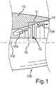
- FIG. 1 shows a portion of a presently only partially illustrated and designed as a gas turbine flow machine 100.
- the turbomachine 100 includes a housing 12, which is presently designed as a turbine intermediate housing.
- a shaft element 102 of the turbomachine 100 rotates within a housing opening 14 of the housing 12.
- hot gas 104 flows through the housing opening 14 of the housing 12 and thereby from a high-pressure turbine side of the turbomachine 100 to a low-pressure turbine side of the turbomachine 100.
- the housing opening 14 is in the present case designed as a channel-like passage opening.
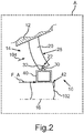
- FIG. 2 shows a regional, schematic representation of the housing 12 according to an in Fig. 1 shown, rimmed area A, wherein a support device 10 is disposed in the through hole 14 of the housing 12.
- the supporting device 10 serves to support forces which occur during operation of the turbomachine 100, such as, for example, an in Fig. 2 Axial force F_A illustrated on the housing 12 by an arrow.
- the supporting device 10 comprises a hub element 40, on which the axial force F_A acts in the present case.
- the support device 10 comprises a plurality of support elements formed as respective struts, of which in the present case only a single support element 20 is shown.
- the support elements may, for example, in each case materially connected to the housing 12, so for example, welded, be.
- the supporting element 20 embodied as a strut serves to hold the hub element 40 on the housing 12.
- the following explanations concerning the support element 20 also apply mutatis mutandis to the further, in Fig. 2 Support elements, not shown, which are arranged circumferentially along the housing 12 in the housing opening 14 and are rotatably connected respectively to the hub member 40.
- the hub member 40 has a passage opening 42 for receiving the shaft member 102, which is presently designed as a rotor shaft of the turbomachine 100, on.
- the axial force F_A can occur, for example, as a result of temperature-induced changes in length of the shaft member 102, to name just one example.
- the support device 10 comprises a plurality of hinges, one of which is connected to a respective one of the support elements and the hub member 40.
- a single pivot 30 is in Fig. 2 shown.
- the hub member 40 is rotatably connected to the support member 20.
- the hinges are presently designed as respective hinge joints. Alternatively, the hinges could also be formed as respective ball joints.
- the rotary joint 30 statements apply mutatis mutandis to the other, in Fig. 2 pivot joints, not shown, which are each coupled to the hub member 40.
- the rotary joint 30 can release at least one relative rotation between the hub member 40 and the support member 20 due to the axial force F_A acting on the hub member 40.
- the rotary joint 30 (and thus all pivots) enables, for example, an operational, axial offset of the hub member 40, for example along a central axis 16 of the housing opening extending through the housing 12, in which the support device 10 is arranged.
- this central axis 16 also corresponds to an element central axis of the hub element 40 and to a shaft axis of the shaft element 102.
- the rotary joint 30 has a joint element 32 which is rotatably received in a recess 22 of the support member 20.
- the recess 22 could also be provided in the hub member 40 and, accordingly, the hinge member 32 inserted into the hub member 40.
- the hinge element 32 is received in a form-fitting manner in the recess 22 of the at least one support element 20.
- FIG. 11 shows a prior art hub strut connection 110 having a strut 114 and a hub 116.
- the strut 114 and the hub 116 are rigidly connected to one another at a connection region 118, for example by a welded connection.
- the strut 114 is welded to a housing component 112.
- an unfavorable S-shaped deformation of the torsionally stiff hub strut connection 110 occurs in the region of the strut 114, such as Fig. 3 can be seen.
- the critical S-shaped deformation can be avoided to form bending-induced, critical stresses.
- the rotary joint 30 favors the uncritical deformation 28 of the respective support element 20. In the uncritical deformation 28 it comes instead of the S-shaped, in Fig. 3 shown deformation only to one, in Fig. 2 shown, bending of the support member 20th
Landscapes
- Engineering & Computer Science (AREA)
- Mechanical Engineering (AREA)
- General Engineering & Computer Science (AREA)
- Chemical & Material Sciences (AREA)
- Combustion & Propulsion (AREA)
- Structures Of Non-Positive Displacement Pumps (AREA)
Abstract
Description
- Die Erfindung betrifft eine Stützvorrichtung für ein Gehäuse einer Strömungsmaschine, zur Abstützung von beim Betrieb der Strömungsmaschine auftretenden Kräften an dem Gehäuse, umfassend zumindest ein Nabenelement sowie wenigstens ein Stützelement zum Halten des Nabenelements an dem Gehäuse. Weitere Aspekte der Erfindung betreffen ein Gehäuse für eine Strömungsmaschine sowie eine Strömungsmaschine.
- Aus der
US 2017/0030223 A1 ist eine Gasturbine bekannt, bei welcher durch eine Mehrzahl an Streben eine metallische Struktur gebildet ist, über welche Last von einer Nabe auf ein Turbinengehäuse der Gasturbine übertragbar ist. Die Nabe stützt einen Rotor und überträgt statische und dynamische Lasten durch die Streben an das Gehäuse. Die Streben sind einteilig mit einer Oberfläche der Nabe ausgebildet und beispielsweise mit der Oberfläche der Nabe verschweißt oder verlötet. Eine derartige Gasturbine ist auch derGB 2 280 484 A - Aufgabe der vorliegenden Erfindung ist es, eine Stützvorrichtung, ein Gehäuse sowie eine Strömungsmaschine der eingangs genannten Art zu schaffen, durch welche eine besonders günstige Lastverteilung von beim Betrieb der Strömungsmaschine auftretenden Kräften ermöglicht ist.
- Diese Aufgabe wird durch eine Stützvorrichtung mit den Merkmalen des Patentanspruchs 1, durch ein Gehäuse mit den Merkmalen des Patentanspruchs 8 sowie durch eine Strömungsmaschine mit den Merkmalen des Patentanspruchs 10 gelöst. Vorteilhafte Ausgestaltungen mit zweckmäßigen Weiterbildungen der Erfindung sind in den Unteransprüchen angegeben.
- Ein erster Aspekt der Erfindung betrifft eine Stützvorrichtung für ein Gehäuse einer Strömungsmaschine, zur Abstützung von beim Betrieb der Strömungsmaschine auftretenden Kräften an dem Gehäuse, umfassend zumindest ein Nabenelement sowie wenigstens ein Stützelement zum Halten des Nabenelements an dem Gehäuse. Das Nabenelement kann zumindest bereichsweise rotationssymmetrisch ausgebildet sein und beispielsweise einen Außenumfang aufweisen, an welchem das Nabenelement mittels des Stützelements oder mehrerer Stützelemente an dem Gehäuse abgestützt sein kann. Das Stützelement kann ein gehäuseseitiges Elementende aufweisen, an welchem das Stützelement bevorzugt stoffschlüssig mit dem Gehäuse verbunden, also beispielsweise mit dem Gehäuse verschweißt, sein kann.
- Gemäß der Erfindung umfasst die Stützvorrichtung wenigstens ein Drehgelenk, mittels welchem das Nabenelement drehbar mit dem Stützelement verbunden ist. Dies ist von Vorteil, da hierdurch eine Übertragung von Biegemomenten, welche durch die beim Betrieb der Strömungsmaschine auftretenden Kräfte hervorgerufen werden können, zwischen dem Stützelement und dem Nabenelement verhindert werden kann. Durch das Verhindern der Übertragung von Biegemomenten kann ein Entstehen von unzulässig hohen, aus den Biegemomenten resultierenden Zugspannungen an einem Verbindungsbereich, an welchem das Stützelement mit dem Nabenelement verbunden ist, wirksam unterbunden werden. Stattdessen ist eine besonders günstige Lastverteilung und Lasteinleitung durch den Einsatz des wenigstens einen Drehgelenks zur Verbindung des Nabenelements mit dem Stützelement gegeben.
- Beim Betrieb der Strömungsmaschine kann das wenigstens eine Drehgelenk einen betriebsbedingten Versatz des Nabenelements, beispielsweise entlang einer Mittelachse einer sich durch das Gehäuse erstreckenden Gehäuseöffnung ermöglichen. Da durch das Drehgelenk eine Relativdrehung zwischen dem Nabenelement und dem Stützelement ermöglicht ist, kann eine kritische Deformation unter Ausbildung von biegemomentbedingten, kritischen Spannungen des Stützelements vermieden werden. Stattdessen begünstigt das Drehgelenk eine unkritische Deformation des Stützelements.
- Im Gegensatz zu einer biegesteifen Verbindung, beispielsweise in Form einer Schweißverbindung oder einer Lötverbindung, zwischen dem Stützelement und dem Nabenelement kann somit durch das wenigstens eine Drehgelenk zumindest eine Relativdrehung um wenigstens eine Drehachse zwischen dem zumindest einen Nabenelement und dem wenigstens einen Stützelement infolge von beim Betrieb der Strömungsmaschine auf das zumindest eine Nabenelement wirkenden Kräften, insbesondere Axialkräften, freigeben werden. Dadurch kann beim Betrieb der Strömungsmaschine eine besonders spannungsarme Belastung der Stützvorrichtung erfolgen.
- In einer vorteilhaften Weiterbildung der Erfindung ist das wenigstens ein Drehgelenk als Scharniergelenk ausgebildet ist. Dies ist von Vorteil, da durch das Scharniergelenk eine gezielte Drehbewegung (Relativdrehung) um eine Drehachse ermöglicht ist. Das Scharniergelenk ermöglicht dementsprechend eine besonders gezielte Lastverteilung bzw. Lasteinleitung von betriebsbedingten Kräften.
- In einer weiteren vorteilhaften Weiterbildung der Erfindung ist das wenigstens ein Drehgelenk als Kugelgelenk ausgebildet. Dies ist von Vorteil, da durch das Kugelgelenk mehrere Drehbewegungen um mehrere Drehachsen ermöglicht sind. Dementsprechend sind durch das Kugelgelenk mehrere Drehfreiheitsgrade freigegeben, wodurch das Übertragen von aus betriebsbedingten Kräften resultierenden Biegemomenten von dem Nabenelement auf das Stützelement sogar vollständig unterbunden werden kann. Dadurch ist eine besonders spannungsarme Lastverteilung ermöglicht.
- In einer weiteren vorteilhaften Weiterbildung der Erfindung weist das wenigstens ein Drehgelenk zumindest ein Gelenkelement auf, welches drehbar in einer Ausnehmung des wenigstens einen Stützelements oder des zumindest einen Nabenelements aufgenommen ist. Dies ist von Vorteil, da hierdurch eine besonders platzsparende Koppelung zwischen dem Stützelement und dem Nabenelement über das Drehgelenk ermöglicht ist. Ein weiterer Vorteil besteht darin, dass durch das drehbare Anordnen des Gelenkelements in der Ausnehmung nicht nur eine Drehbewegung zwischen dem Stützelement und dem Nabenelement ermöglicht ist, sondern auch ein Schwenkwinkel zwischen dem Stützelement und dem Nabenelement besonders aufwandsarm eingeschränkt werden kann. Dies ist damit zu begründen, dass das Gelenkelement durch dessen Aufnahme in der Ausnehmung gleichzeitig einen Anschlag ausbilden kann, bei welchem das Gelenkelement bei Erreichen eines maximal zulässigen Schwenkwinkels an mehreren Stellen an dem Stützelement abgestützt sein kann.
- In einer weiteren vorteilhaften Weiterbildung der Erfindung ist das zumindest eine Gelenkelement formschlüssig in der Ausnehmung des wenigstens einen Stützelements oder des zumindest einen Nabenelements aufgenommen. Dies ist von Vorteil, da durch die formschlüssige Aufnahme eine besonders verliersicher Koppelung zwischen dem Gelenkelement und dem Stützelement oder dem Nabenelement geschaffen ist. Des Weiteren ist durch die formschlüssige Aufnahme eine besonders belastbare Drehverbindung geschaffen, bei welcher eine besonders großflächige Kraftverteilung zwischen dem Gelenkelement und dem Stützelement erfolgen kann.
- In einer weiteren vorteilhaften Weiterbildung der Erfindung ist das wenigstens eine Stützelement als Strebe ausgebildet. Dies ist von Vorteil, da eine derartige Strebe einen besonders einfachen Aufbau aufweist und eine Abstützung des Nabenelements bzw. von betriebsbedingten Kräften an dem Gehäuse unter einem besonders günstigen Kraftfluss ermöglicht.
- In einer weiteren vorteilhaften Weiterbildung der Erfindung weist das zumindest eine Nabenelement eine Durchgangsöffnung zur Aufnahme eines Wellenelements, insbesondere einer Rotorwelle, der Strömungsmaschine auf. Dies ist von Vorteil, da mittels des Nabenelements eine besonders günstige Lagerung des Wellenelements sowie ein spannungsarmer Kraftfluss von betriebsbedingten Kräften zwischen dem Wellenelement und dem Gehäuse ermöglicht ist.
- Bevorzugt kann das Nabenelement dazu ausgebildet sein das Wellenelement zumindest mittelbar abzustützen. Ein mittelbares Abstützen kann beispielsweise über ein an dem Nabenelement angeordnetes, insbesondere fixiertes, Lagerelement, beispielsweise in Form eines Wälzlagers erfolgen. In der Einbaulage der Stützvorrichtung und damit bei deren bestimmungsgemäßem Gebrauch kann das Lagerelement also zwischen dem Nabenelement und dem Wellenelement angeordnet, insbesondere fixiert, sein.
- Ein zweiter Aspekt der Erfindung betrifft ein Gehäuse für eine Strömungsmaschine, mit zumindest einer Stützvorrichtung gemäß dem ersten Aspekt der Erfindung. Durch ein derartiges Gehäuse ist besonders günstige Lastverteilung von beim Betrieb der Strömungsmaschine auftretenden Kräften ermöglicht.
- In einer vorteilhaften Weiterbildung der Erfindung ist das Gehäuse als Turbinenzwischengehäuse ausgebildet. Dies ist von Vorteil, da das Turbinenzwischengehäuse eine besonders günstige Schnittstelle zwischen einer Hochdruckturbinenseite und einer Niederdruckturbinenseite der Strömungsmaschine darstellen kann. Über das Turbinenzwischengehäuse kann Heißgas mit einer Gastemperatur von über 1000 °C von der Hochdruckturbinenseite zu der Niederdruckturbinenseite strömen. Durch die günstige Lastverteilung, welche durch die Stützvorrichtung erzielbar ist, weist das mit der Stützvorrichtung ausgestattete, also die Stützvorrichtung umfassende, Turbinenzwischengehäuse ein besonders spannungsarmes Verformungsverhalten (Deformationsverhalten) selbst bei einem Durchtreten des Heißgases durch das Turbinenzwischengehäuse mit einer derart hohen Gastemperatur auf.
- Ein dritter Aspekt der Erfindung betrifft eine Strömungsmaschine, mit wenigstens einer Stützvorrichtung gemäß dem ersten Aspekt der Erfindung und/oder mit einem Gehäuse gemäß dem zweiten Aspekt der Erfindung. Bei einer derartigen Strömungsmaschine ist eine besonders günstige Lastverteilung von beim Betrieb der Strömungsmaschine auftretenden Kräften ermöglicht.
- In einer vorteilhaften Weiterbildung der Erfindung ist die Strömungsmaschine eine Gasturbine. Eine Gasturbine weist einen besonders hohen Wirkungsgrad auf. Zudem weist eine mit der Stützvorrichtung ausgestattete Gasturbine selbst bei hohen Gastemperatur bzw. großen betriebsbedingten Kräften ein besonders günstiges Verformungsverhalten auf.
- Die Ausführungen zu einem der Aspekte der Erfindung, insbesondere zu einzelnen Merkmalen dieses Aspektes, gelten entsprechend auch analog für die anderen Aspekte der Erfindung.
- Weitere Merkmale der Erfindung ergeben sich aus den Ansprüchen, den Figuren und der Figurenbeschreibung. Die vorstehend in der Beschreibung genannten Merkmale und Merkmalskombinationen, sowie die nachfolgend in der Figurenbeschreibung genannten und/oder in den Figuren alleine gezeigten Merkmale und Merkmalskombinationen sind nicht nur in der jeweils angegebenen Kombination, sondern auch in anderen Kombinationen verwendbar, ohne den Rahmen der Erfindung zu verlassen. Es sind somit auch Ausführungen von der Erfindung als umfasst und offenbart anzusehen, die in den Figuren nicht explizit gezeigt und erläutert sind, jedoch durch separierte Merkmalskombinationen aus den erläuterten Ausführungen hervorgehen und erzeugbar sind. Es sind auch Ausführungen und Merkmalskombinationen als offenbart anzusehen, die somit nicht alle Merkmale eines ursprünglich formulierten unabhängigen Anspruchs aufweisen. Es sind darüber hinaus Ausführungen und Merkmalskombinationen, insbesondere durch die oben dargelegten Ausführungen, als offenbart anzusehen, die über die in den Rückbezügen der Ansprüche dargelegten Merkmalskombinationen hinausgehen oder von diesen abweichen.
- Dabei zeigt:
-
Fig. 1 einen Teilbereich einer Strömungsmaschine; -
Fig. 2 eine bereichsweise, schematische Darstellung eines Gehäuses der Strömungsmaschine sowie einer an dem Gehäuse befestigten Stützvorrichtung gemäß eines inFig. 1 gezeigten Bereichs A; -
Fig. 3 eine schematische Darstellung einer aus dem Stand der Technik bekannten Naben-Streben-Verbindung. -
FIG. 1 zeigt einen Teilbereich einer vorliegend lediglich bereichsweise dargestellten und als Gasturbine ausgebildeten Strömungsmaschine 100. Die Strömungsmaschine 100 umfasst ein Gehäuse 12, welches vorliegend als Turbinenzwischengehäuse ausgebildet ist. Beim Betrieb der Strömungsmaschine 100 rotiert ein Wellenelement 102 der Strömungsmaschine 100 innerhalb einer Gehäuseöffnung 14 des Gehäuses 12. Zudem strömt Heißgas 104 durch die Gehäuseöffnung 14 des Gehäuses 12 und dabei von einer Hochdruckturbinenseite der Strömungsmaschine 100 zu einer Niederdruckturbinenseite der Strömungsmaschine 100. Die Gehäuseöffnung 14 ist vorliegend als kanalartige Durchgangsöffnung ausgebildet. -
FIG. 2 zeigt eine bereichsweise, schematische Darstellung des Gehäuses 12 gemäß eines inFig. 1 gezeigten, umrandeten Bereichs A, wobei eine Stützvorrichtung 10 in der Durchgangsöffnung 14 des Gehäuses 12 angeordnet ist. Die Stützvorrichtung 10 dient zur Abstützung von beim Betrieb der Strömungsmaschine 100 auftretenden Kräften, wie beispielsweise einer inFig. 2 durch einen Pfeil verdeutlichten Axialkraft F_A an dem Gehäuse 12. Die Stützvorrichtung 10 umfasst ein Nabenelement 40, an welchem vorliegend die Axialkraft F_A angreift. - Des Weiteren umfasst die Stützvorrichtung 10 eine Mehrzahl von als jeweilige Streben ausgebildeten Stützelementen, von welchen vorliegend lediglich ein einzelnes Stützelement 20 gezeigt ist. Die Stützelemente können beispielsweise jeweils stoffschlüssig mit dem Gehäuse 12 verbunden, also beispielsweise verschweißt, sein. Das als Strebe ausgebildete Stützelement 20 dient zum Halten des Nabenelements 40 an dem Gehäuse 12. Die nachfolgenden, das Stützelement 20 betreffenden Ausführungen gelten sinngemäß auch für die weiteren, in
Fig. 2 nicht dargestellten Stützelemente, welche umfangsseitig entlang dem Gehäuse 12 in der Gehäuseöffnung 14 angeordnet und jeweils mit dem Nabenelement 40 drehbar verbunden sind. - Das Nabenelement 40 weist eine Durchgangsöffnung 42 zur Aufnahme des Wellenelements 102, welches vorliegend als Rotorwelle der Strömungsmaschine 100 ausgebildet ist, auf. Die Axialkraft F_A kann beispielsweise infolge von temperaturbedingten Längenänderungen des Wellenelements 102 auftreten, um nur ein Beispiel zu nennen.
- Die Stützvorrichtung 10 umfasst mehrere Drehgelenke, von welchen jeweils eines mit jeweils einem der Stützelemente sowie mit dem Nabenelement 40 verbunden ist. Vorliegend ist lediglich ein einziges Drehgelenk 30 in
Fig. 2 gezeigt. Mittels der Drehgelenke ist das Nabenelement 40 drehbar mit dem Stützelement 20 verbunden. Die Drehgelenke sind vorliegend als jeweilige Scharniergelenke ausgebildet. Alternativ dazu könnten die Drehgelenke auch als jeweilige Kugelgelenke ausgebildet sein. Die nachfolgenden, das Drehgelenk 30 betreffenden Ausführungen gelten sinngemäß auch für die weiteren, inFig. 2 nicht dargestellten Drehgelenke, welche jeweils mit dem Nabenelement 40 gekoppelt sind. - Das Drehgelenk 30 kann zumindest eine Relativdrehung zwischen dem Nabenelement 40 und dem Stützelement 20 infolge der auf das Nabenelement 40 wirkenden Axialkraft F_A freigeben.
- Beim Betrieb der Strömungsmaschine 100 ermöglicht das Drehgelenk 30 (und damit sämtliche Drehgelenke) beispielsweise einen betriebsbedingten, axialen Versatz des Nabenelements 40, beispielsweise entlang einer Mittelachse 16 der sich durch das Gehäuse 12 erstreckenden Gehäuseöffnung, in welcher die Stützvorrichtung 10 vorliegend angeordnet ist. Diese Mittelachse 16 entspricht vorliegend auch einer Elementmittelachse des Nabenelements 40 sowie einer Wellenachse des Wellenelements 102. Beim Versatz des Nabenelements 40 kommt es zu einer unkritischen Deformation 28 in Form einer zumindest geringfügigen Durchbiegung des Stützelements 20. Dabei wird ein Auftreten von kritischen Spannungen in der Stützvorrichtung 10 und insbesondere im Stützelement 20 zumindest weitgehend vermieden.
- Das Drehgelenk 30 weist ein Gelenkelement 32 auf, welches drehbar in einer Ausnehmung 22 des Stützelements 20 aufgenommen ist. Alternativ dazu könnte die Ausnehmung 22 auch in dem Nabenelement 40 vorgesehen und dementsprechend das Gelenkelement 32 in das Nabenelement 40 eingeführt sein. Das Gelenkelement 32 ist formschlüssig in der Ausnehmung 22 des wenigstens einen Stützelements 20 aufgenommen.
-
FIG. 3 zeigt eine aus dem Stand der Technik bekannte Naben-Streben-Verbindung 110, welche eine Strebe 114 und eine Nabe 116 aufweist. Die Strebe 114 und die Nabe 116 sind an einem Verbindungsbereich 118 biegesteif, beispielsweise durch eine Schweißverbindung, miteinander verbunden. Die Strebe 114 ist dabei mit einer Gehäusekomponente 112 verschweißt. Infolge der auf die Nabe 116 wirkenden Axialkraft F_A kommt es zu einer Verschiebung der Nabe 116 und dadurch zum Auftreten eines kritischen, inFig. 3 gestrichelt gekennzeichneten, Spannungsbereichs 120, an welchem unzulässig große Spannungen auftreten können. Des Weiteren tritt eine ungünstige, S-förmige Deformation der torsionssteifen Naben-Streben-Verbindung 110 im Bereich der Strebe 114 auf, wieFig. 3 zu entnehmen ist. - Der in
Fig. 3 gezeigte, ungünstige Spannungsbereich 120 sowie die S-förmige Deformation treten bei der Stützvorrichtung 10 aufgrund der Drehgelenke hingegen nicht auf. Dementsprechend wird auch das Auftreten von unzulässig großen Zugspannungen in der Stützvorrichtung 10 durch die Drehgelenke wirksam unterbunden. Durch die Drehgelenke wird eine jeweilige Gelenksstelle geschaffen, welche eine im Vergleich zu der aus dem Stand der Technik bekannten Naben-Streben-Verbindung 110 verbesserte, lastgerechte Spannungsverteilung ermöglicht. - Da durch das Drehgelenk 30 eine Relativdrehung zwischen dem Nabenelement 40 und dem Stützelement 20 ermöglicht ist, kann also mit anderen Worten die kritische S-förmige Deformation unter Ausbildung von biegemomentbedingten, kritischen Spannungen vermieden werden. Stattdessen begünstigt das Drehgelenk 30 die unkritische Deformation 28 des jeweiligen Stützelements 20. Bei der unkritischen Deformation 28 kommt es statt der S-förmigen, in
Fig. 3 gezeigten Deformation lediglich zu einem, inFig. 2 gezeigten, Durchbiegen des Stützelements 20. -
- 10
- Stützvorrichtung
- 12
- Gehäuse
- 14
- Gehäuseöffnung
- 16
- Mittelachse
- 20
- Stützelement
- 22
- Ausnehmung
- 28
- Deformation
- 30
- Drehgelenk
- 32
- Gelenkelement
- 40
- Nabenelement
- 42
- Durchgangsöffnung
- 100
- Strömungsmaschine
- 102
- Wellenelement
- 104
- Heißgas
- 110
- Naben-Streben-Verbindung
- 112
- Gehäusekomponente
- 114
- Strebe
- 116
- Nabe
- 118
- Verbindungsbereich
- 120
- Spannungsbereich
- F_A
- Axialkraft
Claims (11)
- Stützvorrichtung (10) für ein Gehäuse (12) einer Strömungsmaschine (100), zur Abstützung von beim Betrieb der Strömungsmaschine (100) auftretenden Kräften an dem Gehäuse (12), umfassend zumindest ein Nabenelement (40) sowie wenigstens ein Stützelement (20) zum Halten des Nabenelements (40) an dem Gehäuse (12),
dadurch gekennzeichnet, dass
die Stützvorrichtung (10) wenigstens ein Drehgelenk (30) umfasst, mittels welchem das Nabenelement (40) drehbar mit dem Stützelement (20) verbunden ist. - Stützvorrichtung (10) nach Anspruch 1,
dadurch gekennzeichnet, dass
das wenigstens ein Drehgelenk (30) als Scharniergelenk ausgebildet ist. - Stützvorrichtung (10) nach Anspruch 1,
dadurch gekennzeichnet, dass
das wenigstens ein Drehgelenk (30) als Kugelgelenk ausgebildet ist. - Stützvorrichtung (10) nach einem der vorhergehenden Ansprüche,
dadurch gekennzeichnet, dass
das wenigstens ein Drehgelenk (30) zumindest ein Gelenkelement (32) aufweist, welches drehbar in einer Ausnehmung (22) des wenigstens einen Stützelements (20) oder des zumindest einen Nabenelements (40) aufgenommen ist. - Stützvorrichtung (10) nach Anspruch 4,
dadurch gekennzeichnet, dass
das zumindest eine Gelenkelement (32) formschlüssig in der Ausnehmung (22) des wenigstens einen Stützelements (20) oder des zumindest einen Nabenelements (40) aufgenommen ist. - Stützvorrichtung (10) nach einem der vorhergehenden Ansprüche,
dadurch gekennzeichnet, dass
das wenigstens eine Stützelement (10) als Strebe ausgebildet ist. - Stützvorrichtung (10) nach einem der vorhergehenden Ansprüche,
dadurch gekennzeichnet, dass
das zumindest eine Nabenelement (40) eine Durchgangsöffnung (42) zur Aufnahme eines Wellenelements (102), insbesondere einer Rotorwelle, der Strömungsmaschine (100) aufweist. - Gehäuse (12) für eine Strömungsmaschine (100), mit zumindest einer Stützvorrichtung (10) nach einem der Ansprüche 1 bis 7.
- Gehäuse (12) nach Anspruch 8,
dadurch gekennzeichnet, dass
das Gehäuse (12) als Turbinenzwischengehäuse ausgebildet ist. - Strömungsmaschine (100), mit wenigstens einer Stützvorrichtung (10) nach einem der Ansprüche 1 bis 7 und/oder mit einem Gehäuse (12) nach Anspruch 8 oder 9.
- Strömungsmaschine (100) nach Anspruch 10,
dadurch gekennzeichnet, dass
die Strömungsmaschine (100) eine Gasturbine ist.
Applications Claiming Priority (1)
| Application Number | Priority Date | Filing Date | Title |
|---|---|---|---|
| DE102017221669.7A DE102017221669A1 (de) | 2017-12-01 | 2017-12-01 | Stützvorrichtung für ein Gehäuse einer Strömungsmaschine, Gehäuse für eine Strömungsmaschine und Strömungsmaschine |
Publications (2)
| Publication Number | Publication Date |
|---|---|
| EP3492712A1 true EP3492712A1 (de) | 2019-06-05 |
| EP3492712B1 EP3492712B1 (de) | 2020-09-16 |
Family
ID=64500257
Family Applications (1)
| Application Number | Title | Priority Date | Filing Date |
|---|---|---|---|
| EP18208584.5A Active EP3492712B1 (de) | 2017-12-01 | 2018-11-27 | Stützvorrichtung für ein gehäuse einer strömungsmaschine, gehäuse für eine strömungsmaschine und strömungsmaschine |
Country Status (4)
| Country | Link |
|---|---|
| US (1) | US20190170017A1 (de) |
| EP (1) | EP3492712B1 (de) |
| DE (1) | DE102017221669A1 (de) |
| ES (1) | ES2825098T3 (de) |
Citations (7)
| Publication number | Priority date | Publication date | Assignee | Title |
|---|---|---|---|---|
| GB2280484A (en) | 1993-07-30 | 1995-02-01 | Gen Electric | Plates for clamping overlapping panels and bands |
| EP2400119A2 (de) * | 2010-06-23 | 2011-12-28 | Honeywell International, Inc. | Rotorspitzenabstand- und Wellendynamik-System und Verfahren für ein Gasturbinentriebwerk |
| EP2626513A1 (de) * | 2012-02-10 | 2013-08-14 | MTU Aero Engines GmbH | Tandem-Schaufelanordnung |
| US20130216361A1 (en) * | 2012-02-22 | 2013-08-22 | Propheter-Hinckley Tracy A | Vane assembly for a gas turbine engine |
| EP2960437A1 (de) * | 2014-06-26 | 2015-12-30 | MTU Aero Engines GmbH | Leitschaufelvorrichtung für eine gasturbine sowie gasturbine mit einer solchen leitschaufelvorrichtung |
| US20170030223A1 (en) | 2014-04-11 | 2017-02-02 | General Electric Company | Turbine center frame fairing assembly |
| DE102016208154A1 (de) * | 2016-05-12 | 2017-11-16 | MTU Aero Engines AG | Eintrittsleitgitter für einen Verdichter, Verdichter und Verfahren zur Herstellung eines Eintrittleitgitters |
Family Cites Families (22)
| Publication number | Priority date | Publication date | Assignee | Title |
|---|---|---|---|---|
| US4119389A (en) * | 1977-01-17 | 1978-10-10 | General Motors Corporation | Radially removable turbine vanes |
| FR2708071B1 (fr) * | 1993-07-21 | 1995-09-01 | Snecma | Bouchon amovible de deux trous. |
| WO2002053924A1 (de) * | 2000-12-29 | 2002-07-11 | Profil Verbindungstechnik Gmbh & Co. Kg | Bolzenelement mit einem schaftteil und einem kugelkopf, zusammenbauteil und verfahren zur herstellung eines bolzenelements |
| US6783319B2 (en) * | 2001-09-07 | 2004-08-31 | General Electric Co. | Method and apparatus for supporting rotor assemblies during unbalances |
| US7861535B2 (en) * | 2007-09-24 | 2011-01-04 | United Technologies Corporation | Self-aligning liner support hanger |
| US8418473B2 (en) * | 2008-06-02 | 2013-04-16 | United Technologies Corporation | Pivoting liner hanger |
| FR2974065B1 (fr) * | 2011-04-14 | 2013-05-10 | Snecma | Procede de montage d'un moteur d'aeronef sur un pylone et attache moteur pour la mise en oeuvre d'un tel procede. |
| US20130042629A1 (en) * | 2011-08-17 | 2013-02-21 | David T. Feindel | Turbomachine load management assembly |
| US9222413B2 (en) * | 2012-07-13 | 2015-12-29 | United Technologies Corporation | Mid-turbine frame with threaded spokes |
| US9217371B2 (en) * | 2012-07-13 | 2015-12-22 | United Technologies Corporation | Mid-turbine frame with tensioned spokes |
| US9587514B2 (en) * | 2012-07-13 | 2017-03-07 | United Technologies Corporation | Vane insertable tie rods with keyed connections |
| US9494109B2 (en) * | 2012-08-15 | 2016-11-15 | United Technologies Corporation | Pivoting ball stop for exhaust duct liner hanger |
| US9249732B2 (en) * | 2012-09-28 | 2016-02-02 | United Technologies Corporation | Panel support hanger for a turbine engine |
| US9341377B2 (en) * | 2012-12-06 | 2016-05-17 | United Technologies Corporation | Spherical collet for mounting a gas turbine engine liner |
| WO2014137553A1 (en) * | 2013-03-06 | 2014-09-12 | United Technologies Coproration | Exhaust system having a flow path liner supported by structural duct segments |
| FR3003896B1 (fr) * | 2013-03-29 | 2015-03-20 | Snecma | Dispositif d'articulation a rotule pour la suspension d'une turbomachine a un pylone ou la suspension d'un equipement au corps de la turbomachine |
| GB201410058D0 (en) * | 2014-06-06 | 2014-07-16 | Rolls Royce Plc | A casing assembly |
| ES2637944T3 (es) * | 2014-06-06 | 2017-10-18 | MTU Aero Engines AG | Disposición de los componentes de una turbina de gas |
| US9790860B2 (en) * | 2015-01-16 | 2017-10-17 | United Technologies Corporation | Cooling passages for a mid-turbine frame |
| US9845692B2 (en) * | 2015-05-05 | 2017-12-19 | General Electric Company | Turbine component connection with thermally stress-free fastener |
| US10502090B2 (en) * | 2016-08-08 | 2019-12-10 | United Technologies Corporation | Borescope plug |
| FR3061928B1 (fr) * | 2017-01-18 | 2019-11-15 | Safran Aircraft Engines | Turbine de turbomachine comprenant un etage distributeur en materiau composite a matrice ceramique |
-
2017
- 2017-12-01 DE DE102017221669.7A patent/DE102017221669A1/de not_active Withdrawn
-
2018
- 2018-11-26 US US16/199,363 patent/US20190170017A1/en not_active Abandoned
- 2018-11-27 ES ES18208584T patent/ES2825098T3/es active Active
- 2018-11-27 EP EP18208584.5A patent/EP3492712B1/de active Active
Patent Citations (7)
| Publication number | Priority date | Publication date | Assignee | Title |
|---|---|---|---|---|
| GB2280484A (en) | 1993-07-30 | 1995-02-01 | Gen Electric | Plates for clamping overlapping panels and bands |
| EP2400119A2 (de) * | 2010-06-23 | 2011-12-28 | Honeywell International, Inc. | Rotorspitzenabstand- und Wellendynamik-System und Verfahren für ein Gasturbinentriebwerk |
| EP2626513A1 (de) * | 2012-02-10 | 2013-08-14 | MTU Aero Engines GmbH | Tandem-Schaufelanordnung |
| US20130216361A1 (en) * | 2012-02-22 | 2013-08-22 | Propheter-Hinckley Tracy A | Vane assembly for a gas turbine engine |
| US20170030223A1 (en) | 2014-04-11 | 2017-02-02 | General Electric Company | Turbine center frame fairing assembly |
| EP2960437A1 (de) * | 2014-06-26 | 2015-12-30 | MTU Aero Engines GmbH | Leitschaufelvorrichtung für eine gasturbine sowie gasturbine mit einer solchen leitschaufelvorrichtung |
| DE102016208154A1 (de) * | 2016-05-12 | 2017-11-16 | MTU Aero Engines AG | Eintrittsleitgitter für einen Verdichter, Verdichter und Verfahren zur Herstellung eines Eintrittleitgitters |
Also Published As
| Publication number | Publication date |
|---|---|
| ES2825098T3 (es) | 2021-05-14 |
| DE102017221669A1 (de) | 2019-06-06 |
| EP3492712B1 (de) | 2020-09-16 |
| US20190170017A1 (en) | 2019-06-06 |
Similar Documents
| Publication | Publication Date | Title |
|---|---|---|
| EP3283732B1 (de) | Leitschaufelverstellvorrichtung und strömungsmaschine | |
| EP3947993B1 (de) | Gondel mit gleitlagerung | |
| EP3524781B1 (de) | Verbindungseinrichtung für eine verstellbare schaufel einer gasturbine | |
| AT522155A4 (de) | Gleitlagerung | |
| DE3124462A1 (de) | "anordnung zur lagerung eines rotors, die auch bei eintritt einer dynamischen unwucht einen sicheren weiterlauf des rotors ermoeglicht" | |
| DE102015004649A1 (de) | Leitschaufelverstellvorrichtung und Strömungsmaschine | |
| EP3728835B1 (de) | Windkraftanlage mit rotornabenverlängerung | |
| EP3550140A1 (de) | Maschinenträger für eine windenergieanlage | |
| DE102013226522A1 (de) | Fixierung und/oder Verspannung eines Planetenbolzens | |
| EP3287608B1 (de) | Innenring für einen leitschaufelkranz einer strömungsmaschine | |
| DE102016000291A1 (de) | Verfahren zum Herstellen einer Flanschverbindung, Verwendung, Flanschverbindung und Windenergieanlage | |
| DE102017221669A1 (de) | Stützvorrichtung für ein Gehäuse einer Strömungsmaschine, Gehäuse für eine Strömungsmaschine und Strömungsmaschine | |
| DE10157576C2 (de) | Drehlagerung mit einer Sollbruchstelle | |
| DE102010018141A1 (de) | Mehrreihiges Wälzlager, insbesondere mehrreihiges Großwälzlager einer Windkraftanlage | |
| WO2024223500A1 (de) | Vorrichtung zur befestigung eines rotorblattes an einem nabenkörper und mehrteilige nabenanordnung für eine windenergieanlage | |
| EP3094890A1 (de) | Bolzensitz mit schlupf | |
| DE102011090096B4 (de) | Scheibenwischvorrichtung | |
| DE102006042067A1 (de) | Windenergieanlage | |
| EP2317081A2 (de) | Variable Turbinen- und/oder Verdichtergeometrie | |
| DE102010012228B4 (de) | Strahltriebwerk mit einer Sollbruchstellenvorrichtung für den Überlastfall | |
| EP2352909B1 (de) | Leitschaufelträger | |
| WO2019122019A1 (de) | Windkraftanlage, rotorsystem, verfahren zur verwendung einer windkraftanlage | |
| DE102004042235A1 (de) | Lageranordnung einer Windenergieanlage | |
| EP2982834B1 (de) | Wälzlager, insbesondere nadellager, zur anordnung an einem drehzapfen einer variablen leitschaufel einer strömungsmaschine | |
| WO2010043666A1 (de) | Axialturbomaschine mit einem laufschaufelkranz und einer dämpfungseinrichtung |
Legal Events
| Date | Code | Title | Description |
|---|---|---|---|
| PUAI | Public reference made under article 153(3) epc to a published international application that has entered the european phase |
Free format text: ORIGINAL CODE: 0009012 |
|
| STAA | Information on the status of an ep patent application or granted ep patent |
Free format text: STATUS: THE APPLICATION HAS BEEN PUBLISHED |
|
| AK | Designated contracting states |
Kind code of ref document: A1 Designated state(s): AL AT BE BG CH CY CZ DE DK EE ES FI FR GB GR HR HU IE IS IT LI LT LU LV MC MK MT NL NO PL PT RO RS SE SI SK SM TR |
|
| AX | Request for extension of the european patent |
Extension state: BA ME |
|
| STAA | Information on the status of an ep patent application or granted ep patent |
Free format text: STATUS: REQUEST FOR EXAMINATION WAS MADE |
|
| 17P | Request for examination filed |
Effective date: 20191203 |
|
| RBV | Designated contracting states (corrected) |
Designated state(s): AL AT BE BG CH CY CZ DE DK EE ES FI FR GB GR HR HU IE IS IT LI LT LU LV MC MK MT NL NO PL PT RO RS SE SI SK SM TR |
|
| GRAP | Despatch of communication of intention to grant a patent |
Free format text: ORIGINAL CODE: EPIDOSNIGR1 |
|
| STAA | Information on the status of an ep patent application or granted ep patent |
Free format text: STATUS: GRANT OF PATENT IS INTENDED |
|
| INTG | Intention to grant announced |
Effective date: 20200417 |
|
| GRAS | Grant fee paid |
Free format text: ORIGINAL CODE: EPIDOSNIGR3 |
|
| GRAA | (expected) grant |
Free format text: ORIGINAL CODE: 0009210 |
|
| STAA | Information on the status of an ep patent application or granted ep patent |
Free format text: STATUS: THE PATENT HAS BEEN GRANTED |
|
| AK | Designated contracting states |
Kind code of ref document: B1 Designated state(s): AL AT BE BG CH CY CZ DE DK EE ES FI FR GB GR HR HU IE IS IT LI LT LU LV MC MK MT NL NO PL PT RO RS SE SI SK SM TR |
|
| REG | Reference to a national code |
Ref country code: GB Ref legal event code: FG4D Free format text: NOT ENGLISH |
|
| REG | Reference to a national code |
Ref country code: CH Ref legal event code: EP |
|
| REG | Reference to a national code |
Ref country code: DE Ref legal event code: R096 Ref document number: 502018002470 Country of ref document: DE |
|
| REG | Reference to a national code |
Ref country code: IE Ref legal event code: FG4D Free format text: LANGUAGE OF EP DOCUMENT: GERMAN |
|
| REG | Reference to a national code |
Ref country code: AT Ref legal event code: REF Ref document number: 1314342 Country of ref document: AT Kind code of ref document: T Effective date: 20201015 |
|
| PG25 | Lapsed in a contracting state [announced via postgrant information from national office to epo] |
Ref country code: GR Free format text: LAPSE BECAUSE OF FAILURE TO SUBMIT A TRANSLATION OF THE DESCRIPTION OR TO PAY THE FEE WITHIN THE PRESCRIBED TIME-LIMIT Effective date: 20201217 Ref country code: SE Free format text: LAPSE BECAUSE OF FAILURE TO SUBMIT A TRANSLATION OF THE DESCRIPTION OR TO PAY THE FEE WITHIN THE PRESCRIBED TIME-LIMIT Effective date: 20200916 Ref country code: BG Free format text: LAPSE BECAUSE OF FAILURE TO SUBMIT A TRANSLATION OF THE DESCRIPTION OR TO PAY THE FEE WITHIN THE PRESCRIBED TIME-LIMIT Effective date: 20201216 Ref country code: NO Free format text: LAPSE BECAUSE OF FAILURE TO SUBMIT A TRANSLATION OF THE DESCRIPTION OR TO PAY THE FEE WITHIN THE PRESCRIBED TIME-LIMIT Effective date: 20201216 Ref country code: FI Free format text: LAPSE BECAUSE OF FAILURE TO SUBMIT A TRANSLATION OF THE DESCRIPTION OR TO PAY THE FEE WITHIN THE PRESCRIBED TIME-LIMIT Effective date: 20200916 Ref country code: HR Free format text: LAPSE BECAUSE OF FAILURE TO SUBMIT A TRANSLATION OF THE DESCRIPTION OR TO PAY THE FEE WITHIN THE PRESCRIBED TIME-LIMIT Effective date: 20200916 |
|
| PGFP | Annual fee paid to national office [announced via postgrant information from national office to epo] |
Ref country code: DE Payment date: 20201125 Year of fee payment: 3 Ref country code: ES Payment date: 20201214 Year of fee payment: 3 Ref country code: FR Payment date: 20201119 Year of fee payment: 3 |
|
| REG | Reference to a national code |
Ref country code: NL Ref legal event code: MP Effective date: 20200916 |
|
| PG25 | Lapsed in a contracting state [announced via postgrant information from national office to epo] |
Ref country code: LV Free format text: LAPSE BECAUSE OF FAILURE TO SUBMIT A TRANSLATION OF THE DESCRIPTION OR TO PAY THE FEE WITHIN THE PRESCRIBED TIME-LIMIT Effective date: 20200916 Ref country code: RS Free format text: LAPSE BECAUSE OF FAILURE TO SUBMIT A TRANSLATION OF THE DESCRIPTION OR TO PAY THE FEE WITHIN THE PRESCRIBED TIME-LIMIT Effective date: 20200916 |
|
| REG | Reference to a national code |
Ref country code: LT Ref legal event code: MG4D |
|
| PG25 | Lapsed in a contracting state [announced via postgrant information from national office to epo] |
Ref country code: LT Free format text: LAPSE BECAUSE OF FAILURE TO SUBMIT A TRANSLATION OF THE DESCRIPTION OR TO PAY THE FEE WITHIN THE PRESCRIBED TIME-LIMIT Effective date: 20200916 Ref country code: SM Free format text: LAPSE BECAUSE OF FAILURE TO SUBMIT A TRANSLATION OF THE DESCRIPTION OR TO PAY THE FEE WITHIN THE PRESCRIBED TIME-LIMIT Effective date: 20200916 Ref country code: EE Free format text: LAPSE BECAUSE OF FAILURE TO SUBMIT A TRANSLATION OF THE DESCRIPTION OR TO PAY THE FEE WITHIN THE PRESCRIBED TIME-LIMIT Effective date: 20200916 Ref country code: PT Free format text: LAPSE BECAUSE OF FAILURE TO SUBMIT A TRANSLATION OF THE DESCRIPTION OR TO PAY THE FEE WITHIN THE PRESCRIBED TIME-LIMIT Effective date: 20210118 Ref country code: RO Free format text: LAPSE BECAUSE OF FAILURE TO SUBMIT A TRANSLATION OF THE DESCRIPTION OR TO PAY THE FEE WITHIN THE PRESCRIBED TIME-LIMIT Effective date: 20200916 Ref country code: CZ Free format text: LAPSE BECAUSE OF FAILURE TO SUBMIT A TRANSLATION OF THE DESCRIPTION OR TO PAY THE FEE WITHIN THE PRESCRIBED TIME-LIMIT Effective date: 20200916 |
|
| REG | Reference to a national code |
Ref country code: ES Ref legal event code: FG2A Ref document number: 2825098 Country of ref document: ES Kind code of ref document: T3 Effective date: 20210514 |
|
| PG25 | Lapsed in a contracting state [announced via postgrant information from national office to epo] |
Ref country code: AL Free format text: LAPSE BECAUSE OF FAILURE TO SUBMIT A TRANSLATION OF THE DESCRIPTION OR TO PAY THE FEE WITHIN THE PRESCRIBED TIME-LIMIT Effective date: 20200916 Ref country code: IS Free format text: LAPSE BECAUSE OF FAILURE TO SUBMIT A TRANSLATION OF THE DESCRIPTION OR TO PAY THE FEE WITHIN THE PRESCRIBED TIME-LIMIT Effective date: 20210116 Ref country code: PL Free format text: LAPSE BECAUSE OF FAILURE TO SUBMIT A TRANSLATION OF THE DESCRIPTION OR TO PAY THE FEE WITHIN THE PRESCRIBED TIME-LIMIT Effective date: 20200916 |
|
| REG | Reference to a national code |
Ref country code: DE Ref legal event code: R097 Ref document number: 502018002470 Country of ref document: DE |
|
| PG25 | Lapsed in a contracting state [announced via postgrant information from national office to epo] |
Ref country code: MC Free format text: LAPSE BECAUSE OF FAILURE TO SUBMIT A TRANSLATION OF THE DESCRIPTION OR TO PAY THE FEE WITHIN THE PRESCRIBED TIME-LIMIT Effective date: 20200916 Ref country code: SK Free format text: LAPSE BECAUSE OF FAILURE TO SUBMIT A TRANSLATION OF THE DESCRIPTION OR TO PAY THE FEE WITHIN THE PRESCRIBED TIME-LIMIT Effective date: 20200916 |
|
| PLBE | No opposition filed within time limit |
Free format text: ORIGINAL CODE: 0009261 |
|
| STAA | Information on the status of an ep patent application or granted ep patent |
Free format text: STATUS: NO OPPOSITION FILED WITHIN TIME LIMIT |
|
| PG25 | Lapsed in a contracting state [announced via postgrant information from national office to epo] |
Ref country code: LU Free format text: LAPSE BECAUSE OF NON-PAYMENT OF DUE FEES Effective date: 20201127 |
|
| REG | Reference to a national code |
Ref country code: BE Ref legal event code: MM Effective date: 20201130 |
|
| 26N | No opposition filed |
Effective date: 20210617 |
|
| PG25 | Lapsed in a contracting state [announced via postgrant information from national office to epo] |
Ref country code: SI Free format text: LAPSE BECAUSE OF FAILURE TO SUBMIT A TRANSLATION OF THE DESCRIPTION OR TO PAY THE FEE WITHIN THE PRESCRIBED TIME-LIMIT Effective date: 20200916 Ref country code: DK Free format text: LAPSE BECAUSE OF FAILURE TO SUBMIT A TRANSLATION OF THE DESCRIPTION OR TO PAY THE FEE WITHIN THE PRESCRIBED TIME-LIMIT Effective date: 20200916 |
|
| PG25 | Lapsed in a contracting state [announced via postgrant information from national office to epo] |
Ref country code: IE Free format text: LAPSE BECAUSE OF NON-PAYMENT OF DUE FEES Effective date: 20201127 Ref country code: IT Free format text: LAPSE BECAUSE OF FAILURE TO SUBMIT A TRANSLATION OF THE DESCRIPTION OR TO PAY THE FEE WITHIN THE PRESCRIBED TIME-LIMIT Effective date: 20200916 |
|
| PG25 | Lapsed in a contracting state [announced via postgrant information from national office to epo] |
Ref country code: TR Free format text: LAPSE BECAUSE OF FAILURE TO SUBMIT A TRANSLATION OF THE DESCRIPTION OR TO PAY THE FEE WITHIN THE PRESCRIBED TIME-LIMIT Effective date: 20200916 Ref country code: MT Free format text: LAPSE BECAUSE OF FAILURE TO SUBMIT A TRANSLATION OF THE DESCRIPTION OR TO PAY THE FEE WITHIN THE PRESCRIBED TIME-LIMIT Effective date: 20200916 Ref country code: CY Free format text: LAPSE BECAUSE OF FAILURE TO SUBMIT A TRANSLATION OF THE DESCRIPTION OR TO PAY THE FEE WITHIN THE PRESCRIBED TIME-LIMIT Effective date: 20200916 |
|
| REG | Reference to a national code |
Ref country code: DE Ref legal event code: R119 Ref document number: 502018002470 Country of ref document: DE |
|
| PG25 | Lapsed in a contracting state [announced via postgrant information from national office to epo] |
Ref country code: MK Free format text: LAPSE BECAUSE OF FAILURE TO SUBMIT A TRANSLATION OF THE DESCRIPTION OR TO PAY THE FEE WITHIN THE PRESCRIBED TIME-LIMIT Effective date: 20200916 |
|
| REG | Reference to a national code |
Ref country code: CH Ref legal event code: PL |
|
| PG25 | Lapsed in a contracting state [announced via postgrant information from national office to epo] |
Ref country code: BE Free format text: LAPSE BECAUSE OF NON-PAYMENT OF DUE FEES Effective date: 20201130 |
|
| PG25 | Lapsed in a contracting state [announced via postgrant information from national office to epo] |
Ref country code: DE Free format text: LAPSE BECAUSE OF NON-PAYMENT OF DUE FEES Effective date: 20220601 |
|
| PG25 | Lapsed in a contracting state [announced via postgrant information from national office to epo] |
Ref country code: FR Free format text: LAPSE BECAUSE OF NON-PAYMENT OF DUE FEES Effective date: 20211130 |
|
| REG | Reference to a national code |
Ref country code: ES Ref legal event code: FD2A Effective date: 20230202 |
|
| PG25 | Lapsed in a contracting state [announced via postgrant information from national office to epo] |
Ref country code: ES Free format text: LAPSE BECAUSE OF NON-PAYMENT OF DUE FEES Effective date: 20211128 |
|
| PG25 | Lapsed in a contracting state [announced via postgrant information from national office to epo] |
Ref country code: NL Free format text: LAPSE BECAUSE OF NON-PAYMENT OF DUE FEES Effective date: 20200923 |
|
| GBPC | Gb: european patent ceased through non-payment of renewal fee |
Effective date: 20221127 |
|
| PG25 | Lapsed in a contracting state [announced via postgrant information from national office to epo] |
Ref country code: LI Free format text: LAPSE BECAUSE OF NON-PAYMENT OF DUE FEES Effective date: 20220630 Ref country code: CH Free format text: LAPSE BECAUSE OF NON-PAYMENT OF DUE FEES Effective date: 20220630 |
|
| PG25 | Lapsed in a contracting state [announced via postgrant information from national office to epo] |
Ref country code: GB Free format text: LAPSE BECAUSE OF NON-PAYMENT OF DUE FEES Effective date: 20221127 |
|
| REG | Reference to a national code |
Ref country code: AT Ref legal event code: MM01 Ref document number: 1314342 Country of ref document: AT Kind code of ref document: T Effective date: 20231127 |
|
| PG25 | Lapsed in a contracting state [announced via postgrant information from national office to epo] |
Ref country code: AT Free format text: LAPSE BECAUSE OF NON-PAYMENT OF DUE FEES Effective date: 20231127 |
|
| PG25 | Lapsed in a contracting state [announced via postgrant information from national office to epo] |
Ref country code: AT Free format text: LAPSE BECAUSE OF NON-PAYMENT OF DUE FEES Effective date: 20231127 |
|
| PGFP | Annual fee paid to national office [announced via postgrant information from national office to epo] |
Ref country code: AT Payment date: 20260410 Year of fee payment: 5 |