EP3492407A1 - Conveyance system and method for conveying workpiece - Google Patents
Conveyance system and method for conveying workpiece Download PDFInfo
- Publication number
- EP3492407A1 EP3492407A1 EP18208551.4A EP18208551A EP3492407A1 EP 3492407 A1 EP3492407 A1 EP 3492407A1 EP 18208551 A EP18208551 A EP 18208551A EP 3492407 A1 EP3492407 A1 EP 3492407A1
- Authority
- EP
- European Patent Office
- Prior art keywords
- conveyance
- magnetic member
- workpiece
- accommodation device
- shelf
- Prior art date
- Legal status (The legal status is an assumption and is not a legal conclusion. Google has not performed a legal analysis and makes no representation as to the accuracy of the status listed.)
- Granted
Links
- 238000000034 method Methods 0.000 title claims description 15
- 230000004308 accommodation Effects 0.000 claims abstract description 96
- 230000007246 mechanism Effects 0.000 claims abstract description 51
- 238000005259 measurement Methods 0.000 claims description 24
- 238000013459 approach Methods 0.000 claims description 13
- 230000009351 contact transmission Effects 0.000 claims description 11
- 230000003028 elevating effect Effects 0.000 claims description 5
- 230000008878 coupling Effects 0.000 description 17
- 238000010168 coupling process Methods 0.000 description 17
- 238000005859 coupling reaction Methods 0.000 description 17
- 238000012986 modification Methods 0.000 description 17
- 230000004048 modification Effects 0.000 description 17
- NJPPVKZQTLUDBO-UHFFFAOYSA-N novaluron Chemical compound C1=C(Cl)C(OC(F)(F)C(OC(F)(F)F)F)=CC=C1NC(=O)NC(=O)C1=C(F)C=CC=C1F NJPPVKZQTLUDBO-UHFFFAOYSA-N 0.000 description 15
- 238000004519 manufacturing process Methods 0.000 description 9
- 230000005415 magnetization Effects 0.000 description 4
- 230000002093 peripheral effect Effects 0.000 description 4
- 230000005540 biological transmission Effects 0.000 description 3
- 230000007423 decrease Effects 0.000 description 2
- 238000007726 management method Methods 0.000 description 2
- 238000012545 processing Methods 0.000 description 2
- 230000002441 reversible effect Effects 0.000 description 2
- 230000001360 synchronised effect Effects 0.000 description 2
- 238000007792 addition Methods 0.000 description 1
- 230000003247 decreasing effect Effects 0.000 description 1
- 238000006073 displacement reaction Methods 0.000 description 1
- 238000006467 substitution reaction Methods 0.000 description 1
- 239000000758 substrate Substances 0.000 description 1
Images






Classifications
-
- B—PERFORMING OPERATIONS; TRANSPORTING
- B65—CONVEYING; PACKING; STORING; HANDLING THIN OR FILAMENTARY MATERIAL
- B65G—TRANSPORT OR STORAGE DEVICES, e.g. CONVEYORS FOR LOADING OR TIPPING, SHOP CONVEYOR SYSTEMS OR PNEUMATIC TUBE CONVEYORS
- B65G1/00—Storing articles, individually or in orderly arrangement, in warehouses or magazines
- B65G1/02—Storage devices
- B65G1/04—Storage devices mechanical
- B65G1/06—Storage devices mechanical with means for presenting articles for removal at predetermined position or level
-
- B—PERFORMING OPERATIONS; TRANSPORTING
- B65—CONVEYING; PACKING; STORING; HANDLING THIN OR FILAMENTARY MATERIAL
- B65G—TRANSPORT OR STORAGE DEVICES, e.g. CONVEYORS FOR LOADING OR TIPPING, SHOP CONVEYOR SYSTEMS OR PNEUMATIC TUBE CONVEYORS
- B65G47/00—Article or material-handling devices associated with conveyors; Methods employing such devices
- B65G47/74—Feeding, transfer, or discharging devices of particular kinds or types
Definitions
- the present invention relates to a conveyance system which carries-in and carries-out a workpiece between a plurality of shelves in which a workpiece is accommodated and a conveyance device and a method for conveying the workpiece using the conveyance system.
- a conveyance system which takes out a workpiece accommodated in a plurality of shelves and conveys the workpiece.
- Japanese Patent No. 5278122 discloses a tray supply device, which includes a tray magazine which can accommodate a tray, on which a plurality of electronic components are mounted, in a plurality of stages, a sub magazine which takes out the tray from the tray magazine, a supply station which receives the taken-out tray, and an elevation mechanism which elevates the sub magazine and conveys the tray between the tray magazine and the supply station.
- the sub magazine includes a plurality of belt conveyance units as a conveyance mechanism for conveying the tray.
- Each belt conveyance unit includes a conveyance motor, a drive pulley which is driven by the conveyance motor, a driven pulley which is rotatably supported, and an endless belt which is wound around the drive pulley and the driven pulley.
- the supply station includes a two-stage belt conveyance unit as a tray placement portion.
- a structure of the belt conveyance unit is the same as those of the sub magazine and the supply station.
- both the sub magazine on a tray-sending side and the supply station on a tray-receiving side have the belt conveyance unit of the same structure. That is, the conveyance motor which drives the endless belt is provided in each of the sub magazine and the supply station, and when the tray is delivered between the sub magazine and the supply station, the conveyance motor is independently driven at each of the sub magazine and the supply station.
- Japanese Patent No. 4120009 discloses a conveyance device which adopts a magnet coupling for transmitting a driving force between a rotating shaft and a driven shaft of a roller conveyor.
- one magnetization cylinder constituting the magnet coupling is fixed to each of a plurality of driven shafts aligned in a conveyance direction of the roller conveyor, and the other magnetization cylinder which corresponds to each magnetization cylinder on the driven shaft side and has the same number as that of the one magnetization cylinder is fixed to the rotating shaft extending in the same conveyance direction.
- a drive motor for driving the endless belt of the belt conveyance unit is provided on the supply station side on which the tray is received in addition to the sub magazine side from which the tray is sent out. Accordingly, the number of motors increases, and thus, a control thereof is complicated. In addition, the number of parts including the motors and control units thereof increases, and thus, a manufacturing cost increases.
- an object of the present invention is to provide a conveyance system capable of decreasing the number of parts so as to reduce a manufacturing cost and stably and smoothly conveying the workpiece, and a method for conveying the workpiece using the conveyance system.
- a conveyance system includes:
- the conveyance device includes a first drive motor, a first conveyance portion which is driven by the first drive motor and thereby conveying the workpiece between the first conveyance portion and the shelves, an elevation mechanism which is configured to move the first drive motor and the first conveyance portion in the vertical direction, a second drive motor, and a first magnetic member which is rotationally driven by the second drive motor.
- Each shelf of the accommodation device includes a second magnetic member to which a rotational driving force of the second drive motor is capable of being transmitted in a non-contact manner due to a rotation of the first magnetic member, and a second conveyance portion which is driven by the rotational driving force of the second drive motor transmitted in the non-contact manner via the first and second magnetic members and thereby performing bringing-in of the workpiece from the first conveyance portion and bringing-out of the workpiece to the first conveyance portion.
- a method for conveying the workpiece using the above mentioned conveyance system including:
- the conveyance device is moved in the vertical direction by the elevation mechanism, and thereby the conveyance device is disposed at the same height as that of the arbitrarily selected shelf of the accommodation device among the plurality of shelves.
- the first conveyance portion is operated by the first drive motor in the conveyance device
- the first magnetic member is rotated by the second drive motor.
- the rotational driving force of the second drive motor is transmitted to a portion between the first magnetic member and the second magnetic member of the adjacent shelf in a non-contact manner, and the second conveyance portion of the adjacent shelf is operated.
- the first conveyance portion and the second conveyance portion are simultaneously operated, and thus, the carrying-in and the carrying-out of the workpiece are performed between the arbitrarily selected shelf of the accommodation device and the conveyance device.
- the second drive motor which operates the second conveyance portion is not provided on the accommodation device side and is provided on the conveyance device side, and thus, the rotational driving force of the second drive motor is transmitted from the first magnetic member of the conveyance device to the second magnetic member of the accommodation device in a non-contact manner. Accordingly, the drive motor for operating the second conveyance portion does not need to have the drive motor for operating the second conveyance portion in each shelf of the accommodation device, and it is possible to provide the conveyance system with a reduced manufacturing cost.
- a gap between the first magnetic member and the second magnetic member is controlled to be an appropriate distance which is determined in advance. Accordingly, even when the accommodation device having the plurality of shelves is not assembled with high dimensional accuracy, it is possible to stably operate a magnet coupling including the first magnetic member and the second magnetic member.
- a conveyance system 1A of a first embodiment of the present invention includes a conveyance device 10 which conveys a workpiece (for example, a tray on which a processing target is placed) W and an accommodation device 50 which accommodates the workpiece W.
- a conveyance device 10 which conveys a workpiece (for example, a tray on which a processing target is placed) W and an accommodation device 50 which accommodates the workpiece W.
- the conveyance device 10 includes a carrying mechanism 11 which carries-out the workpiece W from the accommodation device 50 and carries-in the workpiece W to the accommodation device 50 and an elevation mechanism 12 which elevates the carrying mechanism 11 in a vertical direction.
- the carrying mechanism 11 includes a base 20, motors (first drive motors) 21A and 21B, a conveyance portion (first conveyance portion) 22, a motor (second drive motor) 23, a magnetic member (first magnetic member) 24, and a single-axis robot (actuator) 25.
- Each mechanism of the conveyance device 10 is mounted on the base 20.
- an electric cylinder may be used as the single-axis robot 25, and the single-axis robot 25 is also mounted on the base 20.
- the conveyance portion 22 is configured of a pair of belt conveyance mechanisms 22A and 22B which are disposed to be separated from each other to be parallel in a delivery direction of the workpiece W between the conveyance device 10 and the accommodation device 50.
- One of the belt conveyance mechanisms 22A includes a drive wheel 27A, a driven wheel 28A which is disposed in a direction separated from the drive wheel 27A in the conveyance direction of the workpiece W, an endless belt 29A which is wound around the drive wheel 27A and the driven wheel 28A, and a plurality of auxiliary wheels 30A which are disposed between the drive wheel 27A and the driven wheel 28A to support the endless belt 29A.
- the drive wheel 27A, the driven wheel 28A, and the auxiliary wheels 30A are provided on a conveyance frame 221 and are rotatable about a horizontal axis orthogonal to the conveyance direction.
- a rotating shaft of the motor 21A is connected to the drive wheel 27A. The motor 21A is operated to drive the drive wheel 27A, and thus, the endless belt 29A travels in a direction moving forward or backward between the drive wheel 27A and the driven wheel 28A.
- the other of the belt conveyance mechanisms 22B includes a drive wheel 27B, a driven wheel 28B which is disposed in a direction separated from the drive wheel 27B in the conveyance direction of the workpiece W, an endless belt 29B which is wound around the drive wheel 27B and the driven wheel 28B, and a plurality of auxiliary wheels 30B which are disposed between the drive wheel 27B and the driven wheel 28B to support the endless belt 29B.
- the drive wheel 27B, the driven wheel 28B, and the auxiliary wheels 30B are provided on a conveyance frame 222 and are rotatable about a horizontal axis orthogonal to the conveyance direction.
- a rotating shaft of the motor 21B is connected to the drive wheel 27B. The motor 21B is operated to drive the drive wheel 27B, and thus, the endless belt 29B travels in a direction moving forward or backward between the drive wheel 27B and the driven wheel 28B.
- the single-axis robot 25 includes an extensible drive shaft 25a.
- An L-shaped pedestal 321 is fixed to a tip of the drive shaft 25a.
- An L-shaped long side portion 321a is disposed on the single-axis robot 25 and an L-shaped short side portion 321b of the pedestal 321 is connected to the tip of the drive shaft 25a.
- a bracket 322 which supports the motor 23 is fixed to the L-shaped long side portion 321a.
- a stepping motor may be used as the motor 23.
- any motor such as a DC motor or an AC motor can be used.
- the drive shaft of the motor 23 is parallel to the conveyance direction of the belt conveyance mechanism 22B and is disposed at a position facing the accommodation device 50 in the vicinity of the belt conveyance mechanism 22B.
- a disk-shaped magnetic member 24 is fixed to the rotating shaft of the motor 23 via a coupling 231. Accordingly, the magnetic member 24 is rotated by driving the motor 23.
- the drive shaft 25a of the single-axis robot 25 moves forward or backward in a direction parallel to the conveyance direction of the workpiece W.
- the pedestal 321, the bracket 322, and the motor 23 are moved forward or backward by the forward or backward movement of the drive shaft 25a. Therefore, the magnetic member 24 fixed to the tip of the rotating shaft of the motor 23 approaches the accommodation device 50 or is separated from the accommodation device 50.
- the elevation mechanism (single-axis robot) 12 is fixed to a side surface of a column 40 standing on a substrate B.
- the elevation mechanism 12 includes a ball screw unit 41, a motor 42 which drives the ball screw unit 41, a control unit 45 (refer to FIG. 1 ) which controls the motor 42, and a slider 43 which is connected to a ball nut (not shown) of the ball screw unit 41 and can be elevated in the vertical direction.
- a portion 201 of the base 20 is fixed to the slider 43.
- the ball screw unit 41 is driven by driving the motor 42, the slider 43 is elevated, and as a result, the base 20 is also elevated.
- the accommodation device 50 includes four columns 51 and a plurality of shelves 52 which are disposed inside the columns 51 and accommodate the workpiece W.
- the plurality of shelves 52 are stacked each other in the vertical direction overlap each other so as to be disposed at equal intervals, and are supported by each of the four columns 51.
- Each shelf 52 includes a delivery mechanism 53 which delivers the workpiece W between the conveyance device 10 and the shelf 52 and a base 54.
- the delivery mechanism 53 includes a magnetic member (second magnetic member) 55 and a conveyance portion (second conveyance portion) 56.
- the magnetic member 55 and the conveyance portion 56 are mounted on the base 54.
- the conveyance portion 56 is configured of a pair of belt conveyance mechanisms 56A and 56B which are parallel to each other so as to be separated from each other in a direction intersecting a delivery direction of the workpiece W between the conveyance device 10 and the accommodation device 50, that is, the same direction as the belt conveyance mechanisms 22A and 22B of the conveyance device 10.
- One of the belt conveyance mechanisms 56A includes a drive wheel 58A which is pivotally supported by a bearing 57a, a driven wheel 59A which is disposed in a direction separated from the drive wheel 58A in the conveyance direction of the workpiece W, an endless belt 60A which is wound around the drive wheel 58A and the driven wheel 59A, and a plurality of auxiliary wheels 64A which are disposed between the drive wheel 58A and the driven wheel 59A to support the endless belt 60A.
- the drive wheel 58A, the driven wheel 59A, and the auxiliary wheels 64A are provided outside (on an upper side in FIG. 1 ) a conveyance frame 561 and are rotatable about a horizontal axis orthogonal to the conveyance direction.
- the drive wheel 58A is connected to a drive shaft 61.
- the other of the belt conveyance mechanisms 56B includes a drive wheel 58B which is pivotally supported by a bearing 57c, a driven wheel 59B which is disposed in a direction separated from the drive wheel 58B in the conveyance direction of the workpiece W, an endless belt 60B which is wound around the drive wheel 58B and the driven wheel 59B, and a plurality of auxiliary wheels 64B which are disposed between the drive wheel 58B and the driven wheel 59B to support the endless belt 60B.
- the drive wheel 58B, the driven wheel 59B, and the auxiliary wheels 64B are provided outside (on a lower side in FIG. 1 ) a conveyance frame 562 and are rotatable about a horizontal axis orthogonal to the conveyance direction.
- the drive wheel 58B is connected to the drive shaft 61.
- the drive wheel 58A and the drive wheel 58B share the drive shaft 61.
- the drive wheel 58 B side of the drive shaft 61 extends outward from the other belt conveyance mechanism 56B in the direction intersecting the above-described delivery direction.
- the magnetic member 55 is provided on one end (an extension end) of the shared drive shaft 61.
- the magnetic member 55 is a disk-shaped member, a center of the magnetic member 55 is fixed to the one end of the drive shaft 61.
- the magnetic member 55 is rotated in the circumferential direction, and thus, the drive wheel 58B and the driven wheel 59B are rotated in the same direction. That is, the magnetic member 55 is rotated, the endless belt 60A rolls between the drive wheel 58A and the driven wheel 59A, and the endless belt 60B rolls between the drive wheel 58B and the driven wheel 59B.
- a guide plate 63a which guides the workpiece W is attached to an outer side (the upper side in FIG. 1 ) of the base 54 in a widthwise direction of the endless belt 60A so as to be along a traveling direction of the endless belt 60A.
- a guide plate 63b which guides the workpiece W is attached to an outer side (the lower side in FIG. 1 ) in a widthwise direction of the endless belt 60B so as to be along a traveling direction of the endless belt 60B.
- Stoppers 65 and 651 which hold the workpiece W on the shelf 52 are provided between the endless belts 60A and 60B on the base 54 of each shelf 52.
- the stopper 65 is installed on one side of the base 54 close to the conveyance device 10 in a standing manner.
- the stopper 651 is installed on the other side of the base 54 far from the conveyance device 10 with respect to the stopper 65 in a standing manner.
- the workpiece W is abutted onto the stopper 651, and thereby a movement of the workpiece W in a direction leaving from the conveyance device 10 is restricted.
- the workpiece W is abutted onto the stopper 65, and thereby a movement of the workpiece W in a direction approaching the conveyance device 10 is restricted.
- the stopper 65 includes an arm 66 which is pivotally supported on the base 54 and a torsion coil spring 67 which biases the arm 66 in a direction in which the arm 66 uprightly stands perpendicularly to the base 54.
- An upper end portion of the arm 66 protrudes from a conveyance surface of each of the endless belts 60A and 60B in a state where the arm 66 stands uprightly, and thereby the upper end portion prevents the workpiece W from moving approach the conveyance device 10.
- a push rod 68 is provided between the endless belts 29A and 29B on the base 20 of the conveyance device 10.
- the push rod 68 is abutted onto the arm 66 of the stopper 65 according to a forward movement of the magnetic member 24 caused by the single-axis robot 25, and tilts the arm 66 in the direction leaving from the conveyance device 10 against a biasing force of the torsion coil spring 67 by a further forward movement of the magnetic member 24. Accordingly, the movement restriction of the workpiece W approaching the conveyance device 10 is canceled, and thereby the workpiece W can be brought-out from the accommodation device 50 to the conveyance device 10 side.
- a base of the push rod 68 is fixed to the pedestal 32.
- a conveyor device 78 which conveys the workpiece W delivered from each shelf 52 to the conveyance device 10 to another step is provided on an upper portion of the accommodation device 50.
- the conveyor device 78 is installed at an upper portion of the column 51, and the workpiece W received by the conveyance device 10 is delivered from the conveyance device 10 to the conveyor device 78. Thereafter, the workpiece W is conveyed in the direction leaving from the conveyance device 10 by driving the conveyance device 78.
- the magnetic coupling is a mechanism in which two disk-shaped magnetic members having N poles and S poles alternately disposed in a circumferential direction are disposed to be close to each other and a non-contact torque transmission can be performed by using a magnetic force acting between the two magnetic members.
- an appropriate distance (D0) is predetermined depending on a magnetic force applied to the magnetic member 24 and the magnetic member 55.
- D0 an appropriate distance
- a protrusion 24a which protrudes toward the accommodation device 50 side is provided at a center of one end surface of the magnetic member 24.
- an abutment member 62 onto which the protrusion 24a is abutted is provided on the base 54 of each shelf 52 of the accommodation device 50.
- Each abutment member 62 includes a smooth side surface portion 62a on the carrying mechanism 11 side.
- the conveyance device 10 includes a control unit 45 which controls the operations of the motors 21A, 21B, and 23 the single-axis robot 25 of the carrying mechanism 11 and the motor 42 of the elevation mechanism 12.
- the control unit 45 operates the motors 21A and 21B synchronously to selectively rotate the drive wheels 27A and 27B in two forward and backward directions at the same rotational speed. Accordingly, the endless belt 29A and the endless belt 29B are always synchronized and travel at a constant speed in the same direction.
- the control unit 45 operates the single-axis robot 25 so as to move the magnetic member 24 forward or backward toward the accommodation device 50 and controls a forward movement amount and a backward movement amount of the magnetic member 24 caused by the single-axis robot 25.
- control unit 45 operates the motor 23 so as to selectively rotate the magnetic member 24 in the two forward and backward directions at a constant speed.
- the magnetic member 24 is rotated, the magnetic member 55 is selectively rotated in the two forward and backward directions at a constant speed according to a rotation direction of the magnetic member 24, the drive wheels 58A and 58B are selectively rotated in the two forward and backward directions at the same rotation speed via the drive shaft 61 connected to the magnetic member 55. Accordingly, the endless belt 60A and the endless belt 60B are always synchronized and travel in the same direction.
- control unit 45 operates the motor 42 of the elevation mechanism 12 and elevates the carrying mechanism 11 for each base 20 in the vertical direction.
- one workpiece W is placed on each shelf 52 of the accommodation device 50. Meanwhile, the workpiece W is not placed on the conveyance device 10. A case where the workpiece W placed on the shelf 52 of a second stage from a bottom of the accommodation device 50 is brought-out to the conveyance device 10 will be described.
- the control unit 45 operates the elevation mechanism 12 of the conveyance device 10 so as to elevate the carrying mechanism 11 for each base 20.
- the control unit 45 controls the elevation of the carrying mechanism 11 such that the carrying mechanism 11 and the shelf 52 (here, the second stage from the bottom) in which the workpiece W to be brought-out is accommodated are positioned at the same height.
- the control unit 45 operates the single-axis robot 25 so as to move the magmatic member 24 forward to the accommodation device 50. Thereafter, when the magnetic member 24 approaches the shelf 52 of the second stage from the bottom, the protrusion 24a provided at the center of the magnetic member 24 is abutted onto the side surface portion 62a of the abutment member 62 of the shelf 52. At this time, the control unit 45 determines that the magnetic member 24 is positioned at a relative position of a distance D1 from the magnetic member 55, stops the forward movement of the single-axis robot 25, and holds the magnetic member 24 at the position.
- the distance D1 at the time of the closest approaching between the magnetic members 24 and 55 is shorter a predetermined distance D0 during operation between the magnetic members 24 and 55.
- the control unit 45 moves the single-axis robot 25 backward by a difference ⁇ D between the distances D0 and D1. Since the difference ⁇ D is predetermined, a size of a gap between the magnetic members 24 and 55 is controlled to the predetermined distance D0 at the time of the operation by the backward movement control of the single-axis robot 25.
- the push rod 68 whose base is fixed to the pedestal 32 also moves forward, and the tip of the push rod 68 is abutted onto the arm 66 of the stopper 65.
- the push rod 68 further moves forward against the biasing force of the torsion coil spring 67, as shown in FIG. 6B , the arm 66 is pressed by the push rod 68 and is tilted. Accordingly, the upper end portion of the arm 66 is retracted below the conveyance surfaces of the endless belts 60A and 60B. Therefore, the movement restriction of the workpiece W toward the conveyance device 10 side is canceled, and the workpiece W from the shelf 52 of the second stage from the bottom can be delivered to the conveyance device 10 side.
- the control unit 45 operates the motor 23 of the carrying mechanism 11, rotates the magnetic member 24 in one direction, and operates the motors 21A and 21B which drive the drive wheel 27A and 27B around which the endless belts 29A and 29B are wound.
- the motor 23 is operated so as to rotate the magnetic member 24 in the one direction (forward direction)
- the magnetic member 55 of the shelf 52 is rotated in the one direction
- the drive wheels 58A and 58B are rotated in the one direction via the drive shaft 61 connected to the magnetic member 55.
- the endless belts 60A and the endless belt 60B travel forward to the conveyance device 10 side, and the workpiece W is sent out from the conveyance portion 56 of the shelf 52 of the second stage from the bottom of the accommodation device 50.
- the drive wheels 27A and 27B are rotated by operating the motors 21A and 21B which drive the drive wheels 27A and 27B around which the endless belts 29A and 29B are wound.
- the rotation speeds and the rotation directions of the motors 21A, 21B, and 23 are controlled to be adjusted in advance such that the rotational speeds and the rotation speeds of the drive wheels 27A and 27B and the drive wheels 58A and 58B are the same as each other.
- the endless belt 29A and the endless belt 29B of the carrying mechanism 11 and the endless belt 60A and the endless belt 60B of the shelf 52 travel forward at a constant speed in the same direction.
- the workpiece W sent out from the conveyance portion 56 of the shelf 52 of the second stage from the bottom of the accommodation device 50 is delivered to the conveyance portion 22 of the conveyance device 10.
- the control unit 45 stops the operations of the motors 21A, 21B, and 23, and thus, the rotations of the drive wheels 27A and 27B and the magnetic member 24 are stopped.
- the single-axis robot 25 is operated, the magnetic member 24 is moved backward from the accommodation device 50, and thus, as shown in FIG. 1 , the magnetic member 24 is moved to a predetermined initial position.
- the driving of the motors 21A, 21B, and 23 may be started individually. For example, first, the driving of only the motor 23 starts. In addition, in a stage in which a tip portion of the workpiece W is brought-out from the shelf 52 to some extent, the driving of the motors 21A and 21B may start such that the workpiece W is transferred from the shelf 52 to the conveyance portion 22. In addition, the driving of the motors 21A and 21B may start after the arm 66 of the stopper 65 is tilted.
- the driving of the motors 21A, 21B, and 23 it is not necessary to stop the driving of the motors 21A, 21B, and 23 at the same timing for all the motors, and the driving of the motors may be stopped individually. For example, in a stage in which the workpiece W is transferred from the shelf 52 to the conveyance portion 22 to some extent, first, the driving of only the motor 23 is stopped. Thereafter, in a state in which the workpiece W is completely transferred to the conveyance portion 22, the driving of the motors 21A and 21B may be stopped.
- the control unit 45 operates the motor 42 of the elevation mechanism 12 of the conveyance device 10 and elevates upward the carrying mechanism 11 on which the workpiece W is placed for each base 20, and thus, the carrying mechanism 11 is positioned at the same position as that of the conveyor device 78.
- the motors 21A and 21B are operated.
- the motors 21A and 21B rotate in a direction opposite to the direction when the workpiece W is brought-out from the conveyance portion 56 of the shelf 52 to the conveyance portion 22 of the conveyance device 10.
- the endless belt 29A and the endless belt 29B travel forward to the conveyance device 78 side, and thus, the workpiece W is sent out from the conveyance portion 22 of the conveyance device 10.
- the conveyance device 78 is operated synchronously with the carrying mechanism 11, the workpiece W sent out from the conveyance device 10 is delivered to the conveyor device 78 and is sent to the next conveyance device, processing device, receiving device, or the like.
- the control unit 45 operates the elevation mechanism 12 of the conveyance device 10. Accordingly, the carrying mechanism 11 is elevated, and the carrying mechanism 11 and an arbitrarily selected shelf 52 to which the workpiece W is to be brought-in are positioned at the same height. Thereafter, the motors and the like are operated in a way opposite of the bringing-out operation of the workpiece W from the shelf 52 to the carrying mechanism 11, and the workpiece W is brought-in from the carrying mechanism 11 to the arbitrary shelf 52.
- the non-contact transmission between the magnetic member 24 and the magnetic member 55 is performed by a rotational driving force of the motor 23 provided in the carrying mechanism 11, and thus, the conveyance portion 56 of the accommodation device 50 is operated.
- the conveyance portion 56 cooperates with the conveyance portion 22 of the conveyance device 10, and thus, the bringing-in and the bringing-out of the workpiece W between the shelf 52 of the accommodation device 50 and the conveyance portion 22 of the conveyance device 10 are performed.
- the rotational driving force of the motor 23 of the conveyance device 10 is transmitted to between the magnetic member 24 of the conveyance portion 22 in the conveyance device 10 and the magnetic member 55 of any shelf 52 in the accommodation device 50 in a non-contact manner, and thus, the conveyance portion 56 of the accommodation device 50 is operated. Accordingly, since it is not necessary to provide the motor for operating the conveyance portion 56 in each shelf 52 of the accommodation device 50, the number of motors can be greatly reduced, and a manufacturing cost of the conveyance system can be suppressed.
- the gap (clearance) between the magnetic members 24 and 55 is required to be an appropriate distance (D0) according to the magnetic force applied to the magnetic members 24 and 55.
- the gap between the magnetic member 24 and the magnetic member 55 is not always the appropriate distance (D0). If each shelf 52 of the accommodation device 50 is manufactured to be assembled to the column 51 with high dimensional accuracy, the gap between the magnetic member 24 and the magnetic member 55 can be maintained to an appropriate distance. However, in order to manage the appropriate distance (D0), high dimensional accuracy of 0.1 mm unit is required. As a result, a manufacturing cost of the accommodation device 50 and further a manufacturing cost of the entire conveyance system increase.
- the gap between the magnetic member 24 and the magnetic member 55 is controlled to be the appropriate distance (D0) which is determined in advance. Accordingly, even in the accommodation device 50 which is assembled with low dimensional accuracy, it is possible to stably operate the magnet coupling including the magnetic member 24 and the magnetic member 55. Therefore, the rotational driving force can be stably transmitted to between the magnetic member 24 and the magnetic member 55 in a non-contact manner.
- FIG. 5A and 5B for example, the case where the magnetic member 24 and the magnetic member 55 is disposed such that the rotating shafts are orthogonal to each other is described.
- the disposition between the magnetic member 24 and the magnetic member 55 is not limited to FIGS. 5A and 5B .
- dispositions such as the following modification examples may be adopted.
- a disposition of the motor 23 on the pedestal 32 is changed, and a direction of the rotating shaft 232 of the magnetic member 24 may be parallel to the direction of the drive shaft 61 of the magnetic member 55 via a gear box 231a such as a bevel gear between the magnetic member 24 and the rotating shaft of the motor 23.
- the protrusion 24a is not provided on the magnetic member 24 and is provided on a tip of the pedestal 32 on the single-axis robot 25 side.
- the control unit 45 operates the single-axis robot 25 so as to move the magnetic member 24 forward to the accommodation device 50.
- the control unit 45 stops the forward movement of the single-axis robot 25.
- the control unit 45 slightly moves the single-axis robot 25 so as to match the size of the gap between the magnetic members 24 and 55 to a predetermined distance at the time of operation.
- the step is transferred to the traveling step and the non-contact transmission drive step of the first embodiment, and the bringing-in of the workpiece W is performed.
- the disposition of the motor 23 on the pedestal 32 is changed, the direction of the rotating shaft 232 of the magnetic member 24 may be parallel to the direction of the drive shaft 61 of the magnetic member 55 via the gear box 231a between the magnetic member 24 and the rotating shaft of the motor 23, and the direction of the rotating shaft of the magnetic member 55 may be orthogonal to the drive shaft 61 via a gear box 69 such as a bevel gear which transmits the driving force generated by the rotation of the magnetic member 55 to the drive shaft 61 between the magnetic member 55 and one end of the drive shaft 61. That is, one side surface of the magnetic member 24 may be disposed to face the peripheral surface of the magnetic member 55. Even in this case, the protrusion 24a is not provided on the magnetic member 24 and is provided on the tip of the pedestal 32 on the single-axis robot 25 side.
- the control unit 45 operates the single-axis robot 25 so as to move the magnetic member 24 toward the accommodation device 50.
- the control unit 45 stops the forward movement of the single-axis robot 25.
- the control unit 45 slightly moves the single-axis robot 25 backward so as to match the size of the gap between the magnetic members 24 and 55 to the predetermined distance at the time of operation.
- the step is transferred to the traveling step and the non-contact transmission drive step of the first embodiment, and the bringing-in of the workpiece W is performed.
- the direction of the rotating shaft 232 of the magnetic member 55 may be orthogonal to the drive shaft 61 via the gear box 69 between the magnetic member 55 and one end of the drive shaft 61. That is, the direction of the rotating shaft 232 of the magnetic member 55 may coincide with the direction of the rotating shaft of the magnetic member 24, and the magnetic member 24 may be disposed so as to face the magnetic member 55.
- a protrusion (second abutment portion) 55a onto which the protrusion (first abutment portion) 24a of the magnetic member 24 is abutted is provided at a center of an end surface of the magnetic member 55 facing the magnetic member 24.
- the control unit 45 controls the single-axis robot 25 to move the magnetic member 24 forward to the accommodation device 50.
- the control unit 45 stops the forward movement of the single-axis robot 25.
- the control unit 45 operates the single-axis robot 25 so as to move the pedestal 32 by a predetermined distance, and thus, the size of the gap between the magnetic members 24 and 55 is matched to the predetermined distance at the time of operation.
- the step is transferred to the traveling step and the non-contact transmission drive step of the first embodiment, and the bringing-in of the workpiece W is performed.
- the protrusion 24a when the protrusion 24a is abutted onto the abutment member 62 of the shelf 52, the forward movement of the single-axis robot 25 is stopped, and thereafter, the single-axis robot 25 is operated to be moved backward, the pedestal 32 is moved backward by a predetermined distance, and the size of the gap between the magnetic members 24 and 55 is matched to the predetermined distance at the time of operation.
- the protrusion 24a may be used as a stopper which predetermines the distance between the conveyance device 10 and each shelf 52 of the accommodation device 50 to a predetermined length, that is, the distance at the time of operation.
- the control unit 45 determines that the size of the gap between the magnetic members 24 and 55 coincides with the predetermined distance at the time of operation, and thereafter, the step is transferred to the traveling step and the non-contact transmission drive step of the first embodiment, and the bringing-in of the workpiece W is performed.
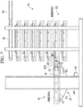
- a conveyance system 1B of a second embodiment of the present invention includes a distance measurement sensor 70 which measures a distance between the conveyance device 10 and each shelf 52 of the accommodation device 50.
- a distance measurement sensor 70 an infrared sensor, a laser displacement sensor (reflection type or transmission type sensor) is adopted.
- the distance measurement sensor 70 is fixed to the pedestal 32 to be adjacent to the motor 23.
- a mirror surface portion 72 which reflects light rays emitted from the distance measurement sensor 70 is provided in each shelf 52 of the accommodation device 50.
- the distance measurement sensor 70 reflects the light rays emitted from the distance measurement sensor 70 to the mirror surface portion 72, and measures the distance between the distance measurement sensor 70 and the mirror surface portion 72.
- the control unit 45 feedforward-controls the forward movement amount of the magnetic member 24 caused by the single-axis robot 25, based on a measurement result of the distance measurement sensor 70.
- a distance D2 between the distance measurement sensor 70 and the mirror surface portion 72 when the gap between the magnetic members 24 and 55 reaches the predetermined distance D0 at the time of operation is obtained in advance.
- the control unit 45 operates the single-axis robot 25 to move the pedestal 32, on which the magnetic member 24 and the distance measurement sensor 70 are mounted, forward to the accommodation device 50.
- the control unit 45 determines that the magnetic member 24 approaches the magnetic member 55 to the predetermined distance D0 at the time of operation.
- the forward movement of the single-axis robot 25 is stopped and the position of the magnetic member 24 with respect to the magnetic member 55 is held at the distance D0 at the time of operation. Thereafter, the step is transferred to the traveling step and the non-contact transmission drive step of the first embodiment, and the bringing-in and the bringing-out of the workpiece W are performed.
- the gap between the magnetic member 24 and the magnetic member 55 is matched to the appropriate distance D0 based on the measurement result of the distance measurement sensor 70, and thus, even in the accommodation device 50 having low dimensional accuracy, it is possible to stably operate the magnet coupling including the magnetic member 24 and the magnetic member 55. In addition, it is possible to shorten the operation time (cycle time) to an extent that does not move the single-axis robot 25 backward, and thus, operation efficiency of the conveyance system 1B is improved.
- the distance measurement sensor 70 is provided on the conveyance device 10 side and the mirror surface portion 72 is provided on the accommodation device 50 side.
- the distance measurement sensor 70 may be provided on the accommodation device 50 side and the mirror surface portion 72 may be provided on the conveyance device 10 side.
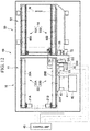
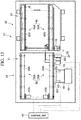
- a conveyance system 1C of a third embodiment of the present invention does not include means for measuring the distance between the conveyance device 10 and each shelf 52 of the accommodation device 50.
- the distance D0 at the time of operation in which the gap between the magnetic members 24 and 55 is predetermined is a known value and is obtained in advance.
- a protrusion amount of the protrusion 24a and/or a position of the side surface portion 62a is adjusted such that the gap between the magnetic members 24 and 55 is the distance D0 at the time of operation.
- the gap between the magnetic members 24 and 55 can be positioned at the distance D0 at the time of operation.
- the control unit 45 determines that the magnetic member 24 approaches the magnetic member 55 to the predetermined distance D0 at the time of operation.
- the forward movement of the single-axis robot 25 is stopped and the position of the magnetic member 24 with respect to the magnetic member 55 is held at the distance D0 at the time of operation. Thereafter, the step is transferred to the traveling step and the non-contact transmission drive step of the first embodiment, and the bringing-in and the bringing-out of the workpiece W are performed.
- a management of the gap between the magnetic members is inferior.
- the number of parts decreases, and a manufacturing cost of the conveyance system can be suppressed at a low cost.
- contact type friction rollers may be combined with each other to transmit the rotational driving force of the motor 23 to the conveyance portion 56 without adopting the non-contact type magnetic coupling between the magnetic members.
- a friction roller 75 is attached to the rotating shaft of the motor 23 instead of the magnetic member
- a friction roller 76 is attached to one end of the drive shaft 61.
- the control unit 45 operates the single-axis robot 25 to move the friction roller 75 forward to the accommodation device 50.
- the forward movement of the single-axis robot 25 is stopped by the controller 45. Thereafter, the step is transferred to the traveling step and the non-contact transmission drive step of the first embodiment, and the bringing-in and the bringing-out of the workpiece W are performed.
- the contact-type friction roller is adopted without adopting the magnet coupling in which the management of the gap between the magnetic members is difficult, and thus, a manufacturing cost of the conveyance system can be suppressed at a low cost.
- the present invention relates to a conveyance system which conveys a workpiece accommodated in a plurality of shelves and a method for conveying the workpiece using the conveyance system.
- the conveyance system it is possible to decrease the number of parts, to suppress the manufacturing cost at a low cost, and to smoothly convey the workpiece.
Landscapes
- Engineering & Computer Science (AREA)
- Mechanical Engineering (AREA)
- Warehouses Or Storage Devices (AREA)
- Intermediate Stations On Conveyors (AREA)
Abstract
Description
- The present invention relates to a conveyance system which carries-in and carries-out a workpiece between a plurality of shelves in which a workpiece is accommodated and a conveyance device and a method for conveying the workpiece using the conveyance system.
- A conveyance system is known which takes out a workpiece accommodated in a plurality of shelves and conveys the workpiece. For example, Japanese Patent No.
5278122 - In the tray supply device, the sub magazine includes a plurality of belt conveyance units as a conveyance mechanism for conveying the tray. Each belt conveyance unit includes a conveyance motor, a drive pulley which is driven by the conveyance motor, a driven pulley which is rotatably supported, and an endless belt which is wound around the drive pulley and the driven pulley. In addition, the supply station includes a two-stage belt conveyance unit as a tray placement portion. In addition, a structure of the belt conveyance unit is the same as those of the sub magazine and the supply station.
- In the tray supply device disclosed in Japanese Patent No.
5278122 - Japanese Patent No.
4120009 - In the conveyance device of Japanese Patent No.
4120009 - Meanwhile, in a conveyance system in which a workpiece accommodated in a plurality of shelves is taken out so as to be conveyed, for example, as described in Japanese Patent No.
5278122 - The present invention is made in consideration of the above-described circumstances, and in a conveyance system which carries-in or carries-out a workpiece between a plurality of shelves accommodating the workpiece and a conveyance device, an object of the present invention is to provide a conveyance system capable of decreasing the number of parts so as to reduce a manufacturing cost and stably and smoothly conveying the workpiece, and a method for conveying the workpiece using the conveyance system.
- According to an aspect of the present invention, a conveyance system includes:
- a conveyance device which is capable of elevating in a vertical direction and thereby conveying a workpiece with its elevation; and
- an accommodation device including a plurality of shelves disposed so as to stack each other in the vertical direction, wherein each of the shelves is capable of accommodating the workpiece, and which is configured to perform bringing-in of the workpiece from the conveyance device to the shelf and bringing-out of the workpiece from the shelf to the conveyance device.
- The conveyance device includes a first drive motor, a first conveyance portion which is driven by the first drive motor and thereby conveying the workpiece between the first conveyance portion and the shelves, an elevation mechanism which is configured to move the first drive motor and the first conveyance portion in the vertical direction, a second drive motor, and a first magnetic member which is rotationally driven by the second drive motor.
- Each shelf of the accommodation device includes a second magnetic member to which a rotational driving force of the second drive motor is capable of being transmitted in a non-contact manner due to a rotation of the first magnetic member, and a second conveyance portion which is driven by the rotational driving force of the second drive motor transmitted in the non-contact manner via the first and second magnetic members and thereby performing bringing-in of the workpiece from the first conveyance portion and bringing-out of the workpiece to the first conveyance portion.
- According to another aspect of the present invention, a method for conveying the workpiece using the above mentioned conveyance system, the method including:
- a first movement step of elevating the conveyance device in the vertical direction to position the conveyance device at the same height as that of an arbitrarily selected shelf among the plurality of shelves;
- a second movement step of operating the actuator to cause the first magnetic member to approach the second magnetic member while maintaining a state where the conveyance device is positioned at the same height as that of the arbitrarily selected shelf;
- a traveling step of operating the first drive motor to travel the first conveyance portion forward or backward; and
- a non-contact transmission drive step of operating the second drive motor to travel the second conveyance portion forward or backward via the first and second magnetic members while maintaining a state where the first magnetic member approaches the second magnetic member.
- According to the present invention, the conveyance device is moved in the vertical direction by the elevation mechanism, and thereby the conveyance device is disposed at the same height as that of the arbitrarily selected shelf of the accommodation device among the plurality of shelves. In addition, at the same time that the first conveyance portion is operated by the first drive motor in the conveyance device, the first magnetic member is rotated by the second drive motor. At this time, the rotational driving force of the second drive motor is transmitted to a portion between the first magnetic member and the second magnetic member of the adjacent shelf in a non-contact manner, and the second conveyance portion of the adjacent shelf is operated. The first conveyance portion and the second conveyance portion are simultaneously operated, and thus, the carrying-in and the carrying-out of the workpiece are performed between the arbitrarily selected shelf of the accommodation device and the conveyance device. The second drive motor which operates the second conveyance portion is not provided on the accommodation device side and is provided on the conveyance device side, and thus, the rotational driving force of the second drive motor is transmitted from the first magnetic member of the conveyance device to the second magnetic member of the accommodation device in a non-contact manner. Accordingly, the drive motor for operating the second conveyance portion does not need to have the drive motor for operating the second conveyance portion in each shelf of the accommodation device, and it is possible to provide the conveyance system with a reduced manufacturing cost.
- According to the present invention, each time the conveyance device is lifted or lowered and is disposed at the same height as that of the arbitrarily selected shelf of the accommodation device, a gap between the first magnetic member and the second magnetic member is controlled to be an appropriate distance which is determined in advance. Accordingly, even when the accommodation device having the plurality of shelves is not assembled with high dimensional accuracy, it is possible to stably operate a magnet coupling including the first magnetic member and the second magnetic member.
-
-
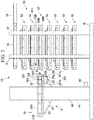
FIG. 1 is a view showing a first embodiment of the present invention and is a plan view of a conveyance device and an accommodation device constituting aconveyance system 1A. -
FIG. 2 is a view showing a first embodiment of the present invention and a front view of the conveyance device and the accommodation device constituting theconveyance system 1A. -
FIG. 3 is a schematic view schematically showing a structure of magnet coupling constituted by a combination ofmagnetic members -
FIG. 4 is a front view explaining carrying-out of a workpiece W from anaccommodation device 50 in theconveyance device 10. -
FIGS. 5A and 5B are views showing a change of a disposition of themagnetic members -
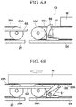
FIGS. 6A and 6B are views explaining a movement of anarm 66 constituting astopper 65 in a stepwise manner. -
FIG. 7 is a front view explaining carrying-out of the workpiece W from theaccommodation device 50 in theconveyance device 10. -
FIG. 8 is a front view explaining delivering of the workpiece W from theconveyance device 10 to aconveyor device 78 in theconveyance device 10. -
FIG. 9 is a plan view showing Modification Example 1 of the first embodiment. -
FIG. 10 is a plan view showing Modification Example 2 of the first embodiment. -
FIG. 11 is a plan view showing Modification Example 3 of the first embodiment. -
FIG. 12 is a view showing a second embodiment of the present invention and is a plan view of a conveyance device and an accommodation device constituting aconveyance system 1B. -
FIG. 13 is a view showing a third embodiment of the present invention and is a plan view of a conveyance device and an accommodation device constituting aconveyance system 1C. -
FIG. 14 is a plan view showing Modification Example 4 adopting a friction roller instead of the magnet coupling. - Hereinafter, a conveyance system and a method for conveying a workpiece according to the present invention will be described.
- As shown in
FIGS. 1 and2 , aconveyance system 1A of a first embodiment of the present invention includes aconveyance device 10 which conveys a workpiece (for example, a tray on which a processing target is placed) W and anaccommodation device 50 which accommodates the workpiece W. - The
conveyance device 10 includes acarrying mechanism 11 which carries-out the workpiece W from theaccommodation device 50 and carries-in the workpiece W to theaccommodation device 50 and anelevation mechanism 12 which elevates thecarrying mechanism 11 in a vertical direction. - The
carrying mechanism 11 includes abase 20, motors (first drive motors) 21A and 21B, a conveyance portion (first conveyance portion) 22, a motor (second drive motor) 23, a magnetic member (first magnetic member) 24, and a single-axis robot (actuator) 25. Each mechanism of theconveyance device 10 is mounted on thebase 20. For example, an electric cylinder may be used as the single-axis robot 25, and the single-axis robot 25 is also mounted on thebase 20. - The
conveyance portion 22 is configured of a pair ofbelt conveyance mechanisms conveyance device 10 and theaccommodation device 50. - One of the
belt conveyance mechanisms 22A includes adrive wheel 27A, a drivenwheel 28A which is disposed in a direction separated from thedrive wheel 27A in the conveyance direction of the workpiece W, anendless belt 29A which is wound around thedrive wheel 27A and the drivenwheel 28A, and a plurality ofauxiliary wheels 30A which are disposed between thedrive wheel 27A and the drivenwheel 28A to support theendless belt 29A. Thedrive wheel 27A, the drivenwheel 28A, and theauxiliary wheels 30A are provided on aconveyance frame 221 and are rotatable about a horizontal axis orthogonal to the conveyance direction. In addition, a rotating shaft of themotor 21A is connected to thedrive wheel 27A. Themotor 21A is operated to drive thedrive wheel 27A, and thus, theendless belt 29A travels in a direction moving forward or backward between thedrive wheel 27A and the drivenwheel 28A. - The other of the
belt conveyance mechanisms 22B includes adrive wheel 27B, a drivenwheel 28B which is disposed in a direction separated from thedrive wheel 27B in the conveyance direction of the workpiece W, anendless belt 29B which is wound around thedrive wheel 27B and the drivenwheel 28B, and a plurality ofauxiliary wheels 30B which are disposed between thedrive wheel 27B and the drivenwheel 28B to support theendless belt 29B. Thedrive wheel 27B, the drivenwheel 28B, and theauxiliary wheels 30B are provided on aconveyance frame 222 and are rotatable about a horizontal axis orthogonal to the conveyance direction. In addition, a rotating shaft of themotor 21B is connected to thedrive wheel 27B. Themotor 21B is operated to drive thedrive wheel 27B, and thus, theendless belt 29B travels in a direction moving forward or backward between thedrive wheel 27B and the drivenwheel 28B. - The single-
axis robot 25 includes anextensible drive shaft 25a. An L-shapedpedestal 321 is fixed to a tip of thedrive shaft 25a. An L-shapedlong side portion 321a is disposed on the single-axis robot 25 and an L-shapedshort side portion 321b of thepedestal 321 is connected to the tip of thedrive shaft 25a. In addition, abracket 322 which supports themotor 23 is fixed to the L-shapedlong side portion 321a. - For example a stepping motor may be used as the
motor 23. In addition, any motor such as a DC motor or an AC motor can be used. The drive shaft of themotor 23 is parallel to the conveyance direction of thebelt conveyance mechanism 22B and is disposed at a position facing theaccommodation device 50 in the vicinity of thebelt conveyance mechanism 22B. A disk-shapedmagnetic member 24 is fixed to the rotating shaft of themotor 23 via acoupling 231. Accordingly, themagnetic member 24 is rotated by driving themotor 23. - The
drive shaft 25a of the single-axis robot 25 moves forward or backward in a direction parallel to the conveyance direction of the workpiece W. Thepedestal 321, thebracket 322, and themotor 23 are moved forward or backward by the forward or backward movement of thedrive shaft 25a. Therefore, themagnetic member 24 fixed to the tip of the rotating shaft of themotor 23 approaches theaccommodation device 50 or is separated from theaccommodation device 50. - The elevation mechanism (single-axis robot) 12 is fixed to a side surface of a
column 40 standing on a substrate B. Theelevation mechanism 12 includes aball screw unit 41, amotor 42 which drives theball screw unit 41, a control unit 45 (refer toFIG. 1 ) which controls themotor 42, and aslider 43 which is connected to a ball nut (not shown) of theball screw unit 41 and can be elevated in the vertical direction. Aportion 201 of thebase 20 is fixed to theslider 43. In addition, in theelevation mechanism 12, theball screw unit 41 is driven by driving themotor 42, theslider 43 is elevated, and as a result, thebase 20 is also elevated. - The
accommodation device 50 includes fourcolumns 51 and a plurality ofshelves 52 which are disposed inside thecolumns 51 and accommodate the workpiece W. - The plurality of
shelves 52 are stacked each other in the vertical direction overlap each other so as to be disposed at equal intervals, and are supported by each of the fourcolumns 51. Eachshelf 52 includes adelivery mechanism 53 which delivers the workpiece W between theconveyance device 10 and theshelf 52 and abase 54. - The
delivery mechanism 53 includes a magnetic member (second magnetic member) 55 and a conveyance portion (second conveyance portion) 56. Themagnetic member 55 and theconveyance portion 56 are mounted on thebase 54. - The
conveyance portion 56 is configured of a pair ofbelt conveyance mechanisms conveyance device 10 and theaccommodation device 50, that is, the same direction as thebelt conveyance mechanisms conveyance device 10. - One of the
belt conveyance mechanisms 56A includes adrive wheel 58A which is pivotally supported by abearing 57a, a drivenwheel 59A which is disposed in a direction separated from thedrive wheel 58A in the conveyance direction of the workpiece W, anendless belt 60A which is wound around thedrive wheel 58A and the drivenwheel 59A, and a plurality ofauxiliary wheels 64A which are disposed between thedrive wheel 58A and the drivenwheel 59A to support theendless belt 60A. Thedrive wheel 58A, the drivenwheel 59A, and theauxiliary wheels 64A are provided outside (on an upper side inFIG. 1 ) aconveyance frame 561 and are rotatable about a horizontal axis orthogonal to the conveyance direction. In addition, thedrive wheel 58A is connected to adrive shaft 61. - The other of the
belt conveyance mechanisms 56B includes adrive wheel 58B which is pivotally supported by abearing 57c, a drivenwheel 59B which is disposed in a direction separated from thedrive wheel 58B in the conveyance direction of the workpiece W, anendless belt 60B which is wound around thedrive wheel 58B and the drivenwheel 59B, and a plurality ofauxiliary wheels 64B which are disposed between thedrive wheel 58B and the drivenwheel 59B to support theendless belt 60B. Thedrive wheel 58B, the drivenwheel 59B, and theauxiliary wheels 64B are provided outside (on a lower side inFIG. 1 ) aconveyance frame 562 and are rotatable about a horizontal axis orthogonal to the conveyance direction. In addition, thedrive wheel 58B is connected to thedrive shaft 61. - The
drive wheel 58A and thedrive wheel 58B share thedrive shaft 61. Thedrive wheel 58 B side of thedrive shaft 61 extends outward from the otherbelt conveyance mechanism 56B in the direction intersecting the above-described delivery direction. Themagnetic member 55 is provided on one end (an extension end) of the shareddrive shaft 61. Like themagnetic member 24, themagnetic member 55 is a disk-shaped member, a center of themagnetic member 55 is fixed to the one end of thedrive shaft 61. Themagnetic member 55 is rotated in the circumferential direction, and thus, thedrive wheel 58B and the drivenwheel 59B are rotated in the same direction. That is, themagnetic member 55 is rotated, theendless belt 60A rolls between thedrive wheel 58A and the drivenwheel 59A, and theendless belt 60B rolls between thedrive wheel 58B and the drivenwheel 59B. - A
guide plate 63a which guides the workpiece W is attached to an outer side (the upper side inFIG. 1 ) of the base 54 in a widthwise direction of theendless belt 60A so as to be along a traveling direction of theendless belt 60A. Aguide plate 63b which guides the workpiece W is attached to an outer side (the lower side inFIG. 1 ) in a widthwise direction of theendless belt 60B so as to be along a traveling direction of theendless belt 60B. -
Stoppers shelf 52 are provided between theendless belts base 54 of eachshelf 52. Thestopper 65 is installed on one side of the base 54 close to theconveyance device 10 in a standing manner. Also, thestopper 651 is installed on the other side of the base 54 far from theconveyance device 10 with respect to thestopper 65 in a standing manner. The workpiece W is abutted onto thestopper 651, and thereby a movement of the workpiece W in a direction leaving from theconveyance device 10 is restricted. Also, the workpiece W is abutted onto thestopper 65, and thereby a movement of the workpiece W in a direction approaching theconveyance device 10 is restricted. In addition, thestopper 65 includes anarm 66 which is pivotally supported on thebase 54 and atorsion coil spring 67 which biases thearm 66 in a direction in which thearm 66 uprightly stands perpendicularly to thebase 54. An upper end portion of thearm 66 protrudes from a conveyance surface of each of theendless belts arm 66 stands uprightly, and thereby the upper end portion prevents the workpiece W from moving approach theconveyance device 10. Meanwhile, apush rod 68 is provided between theendless belts base 20 of theconveyance device 10. Thepush rod 68 is abutted onto thearm 66 of thestopper 65 according to a forward movement of themagnetic member 24 caused by the single-axis robot 25, and tilts thearm 66 in the direction leaving from theconveyance device 10 against a biasing force of thetorsion coil spring 67 by a further forward movement of themagnetic member 24. Accordingly, the movement restriction of the workpiece W approaching theconveyance device 10 is canceled, and thereby the workpiece W can be brought-out from theaccommodation device 50 to theconveyance device 10 side. A base of thepush rod 68 is fixed to thepedestal 32. - As shown in
FIG. 2 , aconveyor device 78 which conveys the workpiece W delivered from eachshelf 52 to theconveyance device 10 to another step is provided on an upper portion of theaccommodation device 50. Theconveyor device 78 is installed at an upper portion of thecolumn 51, and the workpiece W received by theconveyance device 10 is delivered from theconveyance device 10 to theconveyor device 78. Thereafter, the workpiece W is conveyed in the direction leaving from theconveyance device 10 by driving theconveyance device 78. - When the carrying
mechanism 11 and theshelf 52 in theaccommodation device 50 are positioned at the same height as each other, as shown inFIG. 3 , an end surface of themagnetic member 24 facing themagnetic member 55 and a peripheral surface of themagnetic member 55 face each other. Therotating shaft 232 of themagnetic member 24 is orthogonal to thedrive shaft 61 of themagnetic member 55. Here, themagnetic member 24 constitutes themagnetic member 55 and the magnet coupling. The magnetic coupling is a mechanism in which two disk-shaped magnetic members having N poles and S poles alternately disposed in a circumferential direction are disposed to be close to each other and a non-contact torque transmission can be performed by using a magnetic force acting between the two magnetic members. As a gap during operation between both themagnetic member 24 on the drive side and themagnetic member 55 on the driven side, an appropriate distance (D0) is predetermined depending on a magnetic force applied to themagnetic member 24 and themagnetic member 55. When themagnetic member 24 is rotated in one direction in a state where themagnetic member 24 and themagnetic member 55 are separated from each other by the appropriate distance (D0), themagnetic member 55 is also rotated in the one direction while being in non-contact with themagnetic member 55 by the magnetic force acting between themagnetic member 24 and themagnetic member 55. When themagnetic member 24 is rotated in a reverse direction, themagnetic member 55 is also rotated in the reverse direction. In the example ofFIG. 3 , when themagnetic member 24 is rotated in a right-handed forward direction (clockwise direction), themagnetic member 55 is rotated in a right-handed backward direction (clockwise direction) inFIG. 3 . Meanwhile, when themagnetic member 24 is rotated in a left-handed backward direction (counterclockwise direction), themagnetic member 55 is rotated in a right-handed forward direction (counterclockwise direction) inFIG. 3 . - As shown in
FIGS. 5A and 5B , aprotrusion 24a which protrudes toward theaccommodation device 50 side is provided at a center of one end surface of themagnetic member 24. Meanwhile, anabutment member 62 onto which theprotrusion 24a is abutted is provided on thebase 54 of eachshelf 52 of theaccommodation device 50. Eachabutment member 62 includes a smoothside surface portion 62a on the carryingmechanism 11 side. When themagnetic member 24 is moved forward to theaccommodation device 50, theprotrusion 24a is abutted onto the smoothside surface portion 62a. All theshelves 52 are adjusted such that positional relationships between themagnetic members 55 and theside surface portions 62a of theabutment member 62 are the same as each other. - The
conveyance device 10 includes acontrol unit 45 which controls the operations of themotors axis robot 25 of the carryingmechanism 11 and themotor 42 of theelevation mechanism 12. - The
control unit 45 operates themotors drive wheels endless belt 29A and theendless belt 29B are always synchronized and travel at a constant speed in the same direction. - The
control unit 45 operates the single-axis robot 25 so as to move themagnetic member 24 forward or backward toward theaccommodation device 50 and controls a forward movement amount and a backward movement amount of themagnetic member 24 caused by the single-axis robot 25. - In addition, the
control unit 45 operates themotor 23 so as to selectively rotate themagnetic member 24 in the two forward and backward directions at a constant speed. When themagnetic member 24 is rotated, themagnetic member 55 is selectively rotated in the two forward and backward directions at a constant speed according to a rotation direction of themagnetic member 24, thedrive wheels drive shaft 61 connected to themagnetic member 55. Accordingly, theendless belt 60A and theendless belt 60B are always synchronized and travel in the same direction. - In addition, the
control unit 45 operates themotor 42 of theelevation mechanism 12 and elevates the carryingmechanism 11 for each base 20 in the vertical direction. - Continuously, a delivering operation of the workpiece W performed between the
conveyance device 10 and theaccommodation device 50 will be described. - As shown in
FIG. 2 , one workpiece W is placed on eachshelf 52 of theaccommodation device 50. Meanwhile, the workpiece W is not placed on theconveyance device 10. A case where the workpiece W placed on theshelf 52 of a second stage from a bottom of theaccommodation device 50 is brought-out to theconveyance device 10 will be described. - In the state of
FIG. 2 , first, thecontrol unit 45 operates theelevation mechanism 12 of theconveyance device 10 so as to elevate the carryingmechanism 11 for each base 20. In addition, as shown inFIG. 4 , thecontrol unit 45 controls the elevation of the carryingmechanism 11 such that the carryingmechanism 11 and the shelf 52 (here, the second stage from the bottom) in which the workpiece W to be brought-out is accommodated are positioned at the same height. - Next, as shown in
FIG. 5A , thecontrol unit 45 operates the single-axis robot 25 so as to move themagmatic member 24 forward to theaccommodation device 50. Thereafter, when themagnetic member 24 approaches theshelf 52 of the second stage from the bottom, theprotrusion 24a provided at the center of themagnetic member 24 is abutted onto theside surface portion 62a of theabutment member 62 of theshelf 52. At this time, thecontrol unit 45 determines that themagnetic member 24 is positioned at a relative position of a distance D1 from themagnetic member 55, stops the forward movement of the single-axis robot 25, and holds themagnetic member 24 at the position. Here, the distance D1 at the time of the closest approaching between themagnetic members magnetic members - After the forward movement of the single-
axis robot 25 stops, as shown inFIG. 5B , thecontrol unit 45 moves the single-axis robot 25 backward by a difference ΔD between the distances D0 and D1. Since the difference ΔD is predetermined, a size of a gap between themagnetic members axis robot 25. - Also, at this time, when the
magnetic member 24 is moved forward to theaccommodation device 50, as shown inFIG. 6A , thepush rod 68 whose base is fixed to thepedestal 32 also moves forward, and the tip of thepush rod 68 is abutted onto thearm 66 of thestopper 65. When thepush rod 68 further moves forward against the biasing force of thetorsion coil spring 67, as shown inFIG. 6B , thearm 66 is pressed by thepush rod 68 and is tilted. Accordingly, the upper end portion of thearm 66 is retracted below the conveyance surfaces of theendless belts conveyance device 10 side is canceled, and the workpiece W from theshelf 52 of the second stage from the bottom can be delivered to theconveyance device 10 side. - Next, the
control unit 45 operates themotor 23 of the carryingmechanism 11, rotates themagnetic member 24 in one direction, and operates themotors drive wheel endless belts motor 23 is operated so as to rotate themagnetic member 24 in the one direction (forward direction), themagnetic member 55 of theshelf 52 is rotated in the one direction, and thedrive wheels drive shaft 61 connected to themagnetic member 55. Accordingly, as shown inFIG. 6B , theendless belts 60A and theendless belt 60B travel forward to theconveyance device 10 side, and the workpiece W is sent out from theconveyance portion 56 of theshelf 52 of the second stage from the bottom of theaccommodation device 50. - Meanwhile, the
drive wheels motors drive wheels endless belts motors drive wheels drive wheels endless belt 29A and theendless belt 29B of the carryingmechanism 11 and theendless belt 60A and theendless belt 60B of theshelf 52 travel forward at a constant speed in the same direction. As a result, as shown inFIG. 7 , the workpiece W sent out from theconveyance portion 56 of theshelf 52 of the second stage from the bottom of theaccommodation device 50 is delivered to theconveyance portion 22 of theconveyance device 10. - After the workpiece W is delivered to the
conveyance portion 22 of theconveyance device 10, thecontrol unit 45 stops the operations of themotors drive wheels magnetic member 24 are stopped. In addition, the single-axis robot 25 is operated, themagnetic member 24 is moved backward from theaccommodation device 50, and thus, as shown inFIG. 1 , themagnetic member 24 is moved to a predetermined initial position. - Here, it is not necessary to start the driving of the
motors motor 23 starts. In addition, in a stage in which a tip portion of the workpiece W is brought-out from theshelf 52 to some extent, the driving of themotors shelf 52 to theconveyance portion 22. In addition, the driving of themotors arm 66 of thestopper 65 is tilted. - In addition, it is not necessary to stop the driving of the
motors shelf 52 to theconveyance portion 22 to some extent, first, the driving of only themotor 23 is stopped. Thereafter, in a state in which the workpiece W is completely transferred to theconveyance portion 22, the driving of themotors - Thereafter, as shown in
FIG. 8 , thecontrol unit 45 operates themotor 42 of theelevation mechanism 12 of theconveyance device 10 and elevates upward the carryingmechanism 11 on which the workpiece W is placed for each base 20, and thus, the carryingmechanism 11 is positioned at the same position as that of theconveyor device 78. Next, themotors motors conveyance portion 56 of theshelf 52 to theconveyance portion 22 of theconveyance device 10. Accordingly, theendless belt 29A and theendless belt 29B travel forward to theconveyance device 78 side, and thus, the workpiece W is sent out from theconveyance portion 22 of theconveyance device 10. Theconveyance device 78 is operated synchronously with the carryingmechanism 11, the workpiece W sent out from theconveyance device 10 is delivered to theconveyor device 78 and is sent to the next conveyance device, processing device, receiving device, or the like. - Meanwhile, in a case where the workpiece W placed on the carrying
mechanism 11 is brought-in to anyshelf 52 of theaccommodation device 50, first, thecontrol unit 45 operates theelevation mechanism 12 of theconveyance device 10. Accordingly, the carryingmechanism 11 is elevated, and the carryingmechanism 11 and an arbitrarily selectedshelf 52 to which the workpiece W is to be brought-in are positioned at the same height. Thereafter, the motors and the like are operated in a way opposite of the bringing-out operation of the workpiece W from theshelf 52 to the carryingmechanism 11, and the workpiece W is brought-in from the carryingmechanism 11 to thearbitrary shelf 52. - In the present embodiment, the non-contact transmission between the
magnetic member 24 and themagnetic member 55 is performed by a rotational driving force of themotor 23 provided in the carryingmechanism 11, and thus, theconveyance portion 56 of theaccommodation device 50 is operated. Theconveyance portion 56 cooperates with theconveyance portion 22 of theconveyance device 10, and thus, the bringing-in and the bringing-out of the workpiece W between theshelf 52 of theaccommodation device 50 and theconveyance portion 22 of theconveyance device 10 are performed. The rotational driving force of themotor 23 of theconveyance device 10 is transmitted to between themagnetic member 24 of theconveyance portion 22 in theconveyance device 10 and themagnetic member 55 of anyshelf 52 in theaccommodation device 50 in a non-contact manner, and thus, theconveyance portion 56 of theaccommodation device 50 is operated. Accordingly, since it is not necessary to provide the motor for operating theconveyance portion 56 in eachshelf 52 of theaccommodation device 50, the number of motors can be greatly reduced, and a manufacturing cost of the conveyance system can be suppressed. - In addition, in order to stably perform the non-contact transmission between the
magnetic member 24 on the drive side and themagnetic member 55 on the driven side, that is, in order to stably operate the magnetic coupling, the gap (clearance) between themagnetic members magnetic members conveyance device 10 is elevated and is positioned at the same height as eachshelf 52 of theaccommodation device 50, the gap between themagnetic member 24 and themagnetic member 55 is not always the appropriate distance (D0). If eachshelf 52 of theaccommodation device 50 is manufactured to be assembled to thecolumn 51 with high dimensional accuracy, the gap between themagnetic member 24 and themagnetic member 55 can be maintained to an appropriate distance. However, in order to manage the appropriate distance (D0), high dimensional accuracy of 0.1 mm unit is required. As a result, a manufacturing cost of theaccommodation device 50 and further a manufacturing cost of the entire conveyance system increase. - In the present embodiment, each time the
conveyance device 10 is elevated and is positioned at the same position as the arbitrarily selectedshelf 52 of theaccommodation device 50, the gap between themagnetic member 24 and themagnetic member 55 is controlled to be the appropriate distance (D0) which is determined in advance. Accordingly, even in theaccommodation device 50 which is assembled with low dimensional accuracy, it is possible to stably operate the magnet coupling including themagnetic member 24 and themagnetic member 55. Therefore, the rotational driving force can be stably transmitted to between themagnetic member 24 and themagnetic member 55 in a non-contact manner. - However, in the present embodiment, as shown in
FIG. 5A and 5B , for example, the case where themagnetic member 24 and themagnetic member 55 is disposed such that the rotating shafts are orthogonal to each other is described. Here, in a case where a similar magnet coupling is configured, the disposition between themagnetic member 24 and themagnetic member 55 is not limited toFIGS. 5A and 5B . For example, dispositions such as the following modification examples may be adopted. - As shown in
FIG. 9 , a disposition of themotor 23 on thepedestal 32 is changed, and a direction of therotating shaft 232 of themagnetic member 24 may be parallel to the direction of thedrive shaft 61 of themagnetic member 55 via agear box 231a such as a bevel gear between themagnetic member 24 and the rotating shaft of themotor 23. In this case, theprotrusion 24a is not provided on themagnetic member 24 and is provided on a tip of thepedestal 32 on the single-axis robot 25 side. - In the present modification example, the
control unit 45 operates the single-axis robot 25 so as to move themagnetic member 24 forward to theaccommodation device 50. When themagnetic member 24 approaches an arbitrarily selectedshelf 52 of theaccommodation device 50 and theprotrusion 24a provided on thepedestal 32 is abutted onto theabutment member 62 of theshelf 52, thecontrol unit 45 stops the forward movement of the single-axis robot 25. Thereafter, thecontrol unit 45 slightly moves the single-axis robot 25 so as to match the size of the gap between themagnetic members - As shown in
FIG. 10 , the disposition of themotor 23 on thepedestal 32 is changed, the direction of therotating shaft 232 of themagnetic member 24 may be parallel to the direction of thedrive shaft 61 of themagnetic member 55 via thegear box 231a between themagnetic member 24 and the rotating shaft of themotor 23, and the direction of the rotating shaft of themagnetic member 55 may be orthogonal to thedrive shaft 61 via agear box 69 such as a bevel gear which transmits the driving force generated by the rotation of themagnetic member 55 to thedrive shaft 61 between themagnetic member 55 and one end of thedrive shaft 61. That is, one side surface of themagnetic member 24 may be disposed to face the peripheral surface of themagnetic member 55. Even in this case, theprotrusion 24a is not provided on themagnetic member 24 and is provided on the tip of thepedestal 32 on the single-axis robot 25 side. - In the present modification example, the
control unit 45 operates the single-axis robot 25 so as to move themagnetic member 24 toward theaccommodation device 50. When themagnetic member 24 approaches an arbitrarily selectedshelf 52 of theaccommodation device 50 and theprotrusion 24a provided on thepedestal 32 is abutted onto the center of themagnetic member 55, thecontrol unit 45 stops the forward movement of the single-axis robot 25. Thereafter, thecontrol unit 45 slightly moves the single-axis robot 25 backward so as to match the size of the gap between themagnetic members - As shown in
FIG. 11 , the direction of therotating shaft 232 of themagnetic member 55 may be orthogonal to thedrive shaft 61 via thegear box 69 between themagnetic member 55 and one end of thedrive shaft 61. That is, the direction of therotating shaft 232 of themagnetic member 55 may coincide with the direction of the rotating shaft of themagnetic member 24, and themagnetic member 24 may be disposed so as to face themagnetic member 55. In addition, a protrusion (second abutment portion) 55a onto which the protrusion (first abutment portion) 24a of themagnetic member 24 is abutted is provided at a center of an end surface of themagnetic member 55 facing themagnetic member 24. - In the present modification example, the
control unit 45 controls the single-axis robot 25 to move themagnetic member 24 forward to theaccommodation device 50. When themagnetic member 24 approaches an arbitrarily selectedshelf 52 of theaccommodation device 50 and theprotrusion 24a of themagnetic member 24 is abutted onto theprotrusion 55a of themagnetic member 55, thecontrol unit 45 stops the forward movement of the single-axis robot 25. Thereafter, thecontrol unit 45 operates the single-axis robot 25 so as to move thepedestal 32 by a predetermined distance, and thus, the size of the gap between themagnetic members - Also in the modification examples 1, 2, and 3, similarly to the first embodiment, it is possible to stably operate the magnet coupling including the
magnetic members - In addition, in the above-described modification example 1, when the
protrusion 24a is abutted onto theabutment member 62 of theshelf 52, the forward movement of the single-axis robot 25 is stopped, and thereafter, the single-axis robot 25 is operated to be moved backward, thepedestal 32 is moved backward by a predetermined distance, and the size of the gap between themagnetic members protrusion 24a may be used as a stopper which predetermines the distance between theconveyance device 10 and eachshelf 52 of theaccommodation device 50 to a predetermined length, that is, the distance at the time of operation. In this case, when theprotrusion 24a is abutted onto theabutment member 62 of theshelf 52, thecontrol unit 45 determines that the size of the gap between themagnetic members - As shown in
FIG. 12 , aconveyance system 1B of a second embodiment of the present invention includes adistance measurement sensor 70 which measures a distance between theconveyance device 10 and eachshelf 52 of theaccommodation device 50. For example, as thedistance measurement sensor 70, an infrared sensor, a laser displacement sensor (reflection type or transmission type sensor) is adopted. Thedistance measurement sensor 70 is fixed to thepedestal 32 to be adjacent to themotor 23. Meanwhile, amirror surface portion 72 which reflects light rays emitted from thedistance measurement sensor 70 is provided in eachshelf 52 of theaccommodation device 50. Thedistance measurement sensor 70 reflects the light rays emitted from thedistance measurement sensor 70 to themirror surface portion 72, and measures the distance between thedistance measurement sensor 70 and themirror surface portion 72. Thecontrol unit 45 feedforward-controls the forward movement amount of themagnetic member 24 caused by the single-axis robot 25, based on a measurement result of thedistance measurement sensor 70. - In the present embodiment, a distance D2 between the
distance measurement sensor 70 and themirror surface portion 72 when the gap between themagnetic members control unit 45 operates the single-axis robot 25 to move thepedestal 32, on which themagnetic member 24 and thedistance measurement sensor 70 are mounted, forward to theaccommodation device 50. When themagnetic member 24 approaches theshelf 52 of the second stage from the bottom and the gap between thedistance measurement sensor 70 and themirror surface portion 72 reaches the predetermined distance D2, thecontrol unit 45 determines that themagnetic member 24 approaches themagnetic member 55 to the predetermined distance D0 at the time of operation. In addition, the forward movement of the single-axis robot 25 is stopped and the position of themagnetic member 24 with respect to themagnetic member 55 is held at the distance D0 at the time of operation. Thereafter, the step is transferred to the traveling step and the non-contact transmission drive step of the first embodiment, and the bringing-in and the bringing-out of the workpiece W are performed. - In the present embodiment, the gap between the
magnetic member 24 and themagnetic member 55 is matched to the appropriate distance D0 based on the measurement result of thedistance measurement sensor 70, and thus, even in theaccommodation device 50 having low dimensional accuracy, it is possible to stably operate the magnet coupling including themagnetic member 24 and themagnetic member 55. In addition, it is possible to shorten the operation time (cycle time) to an extent that does not move the single-axis robot 25 backward, and thus, operation efficiency of theconveyance system 1B is improved. - In the present embodiment, the
distance measurement sensor 70 is provided on theconveyance device 10 side and themirror surface portion 72 is provided on theaccommodation device 50 side. However, thedistance measurement sensor 70 may be provided on theaccommodation device 50 side and themirror surface portion 72 may be provided on theconveyance device 10 side. - As shown in
FIG. 13 , aconveyance system 1C of a third embodiment of the present invention does not include means for measuring the distance between theconveyance device 10 and eachshelf 52 of theaccommodation device 50. In the present embodiment, the distance D0 at the time of operation in which the gap between themagnetic members protrusion 24a of themagnetic member 24 is abutted onto theside surface portion 62a of theabutment member 62 of theshelf 52, a protrusion amount of theprotrusion 24a and/or a position of theside surface portion 62a is adjusted such that the gap between themagnetic members axis robot 25 forward using thecontrol unit 45 and causing theprotrusion 24a of themagnetic member 24 to abut onto theside surface portion 62a of theabutment member 62, the gap between themagnetic members control unit 45 determines that themagnetic member 24 approaches themagnetic member 55 to the predetermined distance D0 at the time of operation. In addition, the forward movement of the single-axis robot 25 is stopped and the position of themagnetic member 24 with respect to themagnetic member 55 is held at the distance D0 at the time of operation. Thereafter, the step is transferred to the traveling step and the non-contact transmission drive step of the first embodiment, and the bringing-in and the bringing-out of the workpiece W are performed. - Compared to the case where the
distance measurement sensor 70 is adopted, a management of the gap between the magnetic members is inferior. However, the number of parts decreases, and a manufacturing cost of the conveyance system can be suppressed at a low cost. In addition, it is possible to shorten the operation time to an extent that does not move the single-axis robot 25 backward, and thus, operation efficiency of theconveyance system 1C is improved. - In addition to the above-described embodiments, the following configuration can be adopted. That is, as shown in
FIG. 14 , contact type friction rollers may be combined with each other to transmit the rotational driving force of themotor 23 to theconveyance portion 56 without adopting the non-contact type magnetic coupling between the magnetic members. - In the present modification example, while a
friction roller 75 is attached to the rotating shaft of themotor 23 instead of the magnetic member, afriction roller 76 is attached to one end of thedrive shaft 61. Thecontrol unit 45 operates the single-axis robot 25 to move thefriction roller 75 forward to theaccommodation device 50. When a peripheral surface of thefriction roller 75 comes into contact with a peripheral surface of thefriction roller 76, the forward movement of the single-axis robot 25 is stopped by thecontroller 45. Thereafter, the step is transferred to the traveling step and the non-contact transmission drive step of the first embodiment, and the bringing-in and the bringing-out of the workpiece W are performed. - In the present modification example, the contact-type friction roller is adopted without adopting the magnet coupling in which the management of the gap between the magnetic members is difficult, and thus, a manufacturing cost of the conveyance system can be suppressed at a low cost. In addition, it is possible to shorten the operation time to an extent that does not move the single-
axis robot 25 backward, and thus, operation efficiency of the conveyance system is improved. - The present invention relates to a conveyance system which conveys a workpiece accommodated in a plurality of shelves and a method for conveying the workpiece using the conveyance system.
- According to the present invention, in the conveyance system, it is possible to decrease the number of parts, to suppress the manufacturing cost at a low cost, and to smoothly convey the workpiece.
- While preferred embodiments of the invention have been described and illustrated above, it should be understood that these are exemplary of the invention and are not to be considered as limiting. Additions, omissions, substitutions, and other modifications can be made without departing from the spirit or scope of the present invention. Accordingly, the invention is not to be considered as being limited by the foregoing description, and is only limited by the scope of the appended claims.
Claims (17)
- A conveyance system, comprising:a conveyance device which is capable of elevating in a vertical direction and thereby conveying a workpiece with its elevation; andan accommodation device including a plurality of shelves disposed so as to stack each other in the vertical direction, each of the shelves is capable of accommodating the workpiece, and which is configured to perform bringing-in of the workpiece from the conveyance device to the shelf and bringing-out of the workpiece from the shelf to the conveyance device,wherein the conveyance device includes:a first drive motor,a first conveyance portion which is driven by the first drive motor and thereby conveying the workpiece between the first conveyance portion and the shelves,an elevation mechanism which is configured to move the first drive motor and the first conveyance portion in the vertical direction,a second drive motor, anda first magnetic member which is rotationally driven by the second drive motor,wherein each shelf of the accommodation device includes:a second magnetic member to which a rotational driving force of the second drive motor is capable of being transmitted in a non-contact manner due to a rotation of the first magnetic member, anda second conveyance portion which is driven by the rotational driving force of the second drive motor transmitted in the non-contact manner via the first and second magnetic members and thereby performing bringing-in of the workpiece from the first conveyance portion and bringing-out of the workpiece to the first conveyance portion.
- The conveyance system according to Claim 1,wherein the conveyance device further includes an actuator which performs moving forward the first magnetic member to the accommodation device and moving backward the first magnetic member from the accommodation device, andwherein the conveyance system further comprises a control unit which is configured to control a forward movement amount and a backward movement amount of the first magnetic member caused by the actuator.
- The conveyance system according to Claim 2,
wherein the accommodation device includes an abutment portion onto which the first magnetic member is abutted. - The conveyance system according to Claim 3,
wherein the control unit is configured to control the forward movement amount and the backward movement amount of the first magnetic member caused by the actuator, according to a state where the first magnetic member is abutted onto the accommodation device via the abutment portion. - The conveyance system according to Claim 2,
wherein the accommodation device includes an abutment portion onto which the actuator is abutted. - The conveyance system according to Claim 5,
wherein the control unit controls the forward movement amount and the backward movement amount of the first magnetic member caused by the actuator, according to a state where the actuator is abutted onto the accommodation device via the abutment portion. - The conveyance system according to Claim 2,wherein the first magnetic member includes a first abutment portion onto which the accommodation device is abutted, andwherein the accommodation device includes a second abutment portion onto which the first abutment portion is abutted.
- The conveyance system according to Claim 7,
wherein the control unit controls the forward movement amount and the backward movement amount of the first magnetic member caused by the actuator, according to a state where the first magnetic member is abutted onto the accommodation device via the first and second abutment portions. - The conveyance system according to Claim 2, further comprising:a distance measurement sensor, which is configured to measure a distance between the conveyance device and the accommodation device, in at least one of the conveyance device and the accommodation device,wherein the control unit controls the forward movement amount of the first magnetic member caused by the actuator, based on a measurement value of the distance measurement sensor.
- The conveyance system according to Claim 2, further comprising:
a stopper, which is configured to define a distance between the conveyance device and the accommodation device to a predetermined length, included in at least one of the conveyance device and the accommodation device. - A method for conveying a workpiece using a conveyance system, wherein the system including: a conveyance device which is capable of elevating in a vertical direction and thereby conveying the workpiece with its elevation, and an accommodation device including a plurality of shelves disposed so as to stack each other in the vertical direction, each of the shelves is capable of accommodating the workpiece, and which performs bringing-in of the workpiece from the conveyance device to the shelf and bringing-out of the workpiece from the shelf to the conveyance device,wherein the conveyance device includes: a first drive motor, a first conveyance portion which is driven by the first drive motor and thereby conveying the workpiece between the first conveyance portion and the shelves, an elevation mechanism which is configured to move the first drive motor and the first conveyance portion in the vertical direction, a second drive motor, and a first magnetic member which is rotationally driven by the second drive motor,wherein each shelf of the accommodation device includes: a second magnetic member to which a rotational driving force of the second drive motor is capable of being transmitted in a non-contact manner due to a rotation of the first magnetic member, and a second conveyance portion which is driven by the rotational driving force of the second drive motor transmitted in the non-contact manner via the first and second magnetic members and thereby performing bringing-in of the workpiece from the first conveyance portion and bringing-out of the workpiece to the first conveyance portion, the method comprising:a first movement step of elevating the conveyance device in the vertical direction to position the conveyance device at the same height as that of an arbitrary selected shelf among the plurality of shelves;a second movement step of operating the actuator to cause the first magnetic member to approach the second magnetic member while maintaining a state where the conveyance device is positioned at the same height as that of the arbitrarily-selected shelf;a traveling step of operating the first drive motor to travel the first conveyance portion forward or backward; anda non-contact transmission drive step of operating the second drive motor to travel the second conveyance portion forward or backward via the first and second magnetic members while maintaining a state where the first magnetic member approaches the second magnetic member.
- The method for conveying a workpiece according to Claim 11,wherein each shelf of the accommodation device further includes an abutment portion onto which the first magnetic member is abutted, andwherein the second movement step includes:a first step of moving the first magnetic member forward to the second magnetic member until the first magnetic member is abutted onto the abutment portion, anda second step of driving the actuator, after the first magnetic member is abutted onto the abutment portion, to move the first magnetic member backward such that a predetermined gap is provided between the first magnetic member and the second magnetic member.
- The method for conveying a workpiece according to Claim 11,wherein each shelf of the accommodation device further includes an abutment portion onto which the actuator is abutted,wherein the second movement step includes:a third step of moving the first magnetic member forward to the second magnetic member until the abutment portion is abutted onto the actuator, anda fourth step of driving the actuator, after the abutment portion is abutted onto the actuator, to move the first magnetic member backward such that a predetermined gap is provided between the first magnetic member and the second magnetic member.
- The method for conveying a workpiece according to Claim 11,wherein the first magnetic member further includes a first abutment portion which is abutted onto the accommodation device,wherein each shelf of the accommodation device further includes a second abutment portion onto which the first abutment portion is abutted, andwherein the second movement step includes:a fifth step of moving the first magnetic member forward to the second magnetic member until the first abutment portion is abutted onto the second abutment portion, anda sixth step of driving the actuator, after the first abutment portion is abutted onto the second abutment portion, to move the first magnetic member backward such that a predetermined gap is provided between the first magnetic member and the second magnetic member.
- The method for conveying a workpiece according to Claim 11,
wherein the second movement step includes:a seventh step of moving the first magnetic member forward to the second magnetic member, andan eighth step of stopping driving of the actuator after a distance between the conveyance device and the accommodation device is set to a predetermined distance. - The method for conveying a workpiece according to Claim 15,wherein the conveyance system further includes a distance measurement sensor, which is configured to measure a distance between the conveyance device and the accommodation device, in at least one of the conveyance device and the accommodation device, andwherein the second movement step further includes a ninth step of measuring the distance between the conveyance device and the accommodation device by the distance measurement sensor, andwherein the actuator is stopped driving of thereof after the distance between the conveyance device and the accommodation device is set to the predetermined distance based on a measurement value of the distance measurement sensor.
- The method for conveying a workpiece according to Claim 11,
wherein the second movement step includes:a tenth step of moving the first magnetic member forward to the second magnetic member, andan eleventh step of stopping driving of the actuator after a stopper installed on one of the conveyance device and the accommodation device is abutted onto the other of the conveyance device and the accommodation device and thereby a distance between the conveyance device and the accommodation device is defined.
Applications Claiming Priority (1)
| Application Number | Priority Date | Filing Date | Title |
|---|---|---|---|
| JP2017229559A JP6584480B2 (en) | 2017-11-29 | 2017-11-29 | Conveying system and workpiece conveying method |
Publications (2)
| Publication Number | Publication Date |
|---|---|
| EP3492407A1 true EP3492407A1 (en) | 2019-06-05 |
| EP3492407B1 EP3492407B1 (en) | 2022-01-26 |
Family
ID=64500240
Family Applications (1)
| Application Number | Title | Priority Date | Filing Date |
|---|---|---|---|
| EP18208551.4A Active EP3492407B1 (en) | 2017-11-29 | 2018-11-27 | Conveyance system and method for conveying workpiece |
Country Status (4)
| Country | Link |
|---|---|
| EP (1) | EP3492407B1 (en) |
| JP (1) | JP6584480B2 (en) |
| CN (1) | CN110015559B (en) |
| ES (1) | ES2907242T3 (en) |
Cited By (3)
| Publication number | Priority date | Publication date | Assignee | Title |
|---|---|---|---|---|
| CN115303784A (en) * | 2022-08-26 | 2022-11-08 | 青岛新威立智能机械科技有限公司 | Workpiece distance separating and conveying device |
| CN115351859A (en) * | 2022-08-26 | 2022-11-18 | 青岛新威立智能机械科技有限公司 | Universal workpiece distance separating and conveying device |
| EP4126708A1 (en) * | 2020-03-24 | 2023-02-08 | Autostore Technology AS | Delivery vehicle, system and method for moving storage containers between a first conveyor on the delivery vehicle and an external conveyor |
Families Citing this family (5)
| Publication number | Priority date | Publication date | Assignee | Title |
|---|---|---|---|---|
| CN110683266A (en) * | 2019-10-21 | 2020-01-14 | 广东高力威机械科技有限公司 | Three-dimensional bin for sheet |
| CN114379984B (en) * | 2020-10-19 | 2024-11-12 | 奥特斯科技(重庆)有限公司 | Magnetic drive device, arrangement and method for conveying component carriers |
| CN113173366B (en) * | 2021-05-12 | 2024-05-10 | 咸宁市诺贝佳机电设备有限公司 | Three-dimensional bin type temporary storage machine |
| CN115193742A (en) * | 2022-06-27 | 2022-10-18 | 苏州富强科技有限公司 | Little battery size detection equipment |
| CN115027934A (en) * | 2022-06-27 | 2022-09-09 | 苏州富强科技有限公司 | Microbattery loading attachment |
Citations (7)
| Publication number | Priority date | Publication date | Assignee | Title |
|---|---|---|---|---|
| US3817406A (en) * | 1973-01-19 | 1974-06-18 | Mitsubishi Heavy Ind Ltd | Automatic storage system with stacker cranes and load handling dollies |
| DE3837402A1 (en) * | 1988-11-01 | 1990-05-03 | Siemens Ag | Store device having a stationary magazine |
| JP2004142902A (en) * | 2002-10-25 | 2004-05-20 | Murata Mach Ltd | Stocker |
| JP4120009B2 (en) | 2003-03-13 | 2008-07-16 | 株式会社エフ・イー・シー | Conveying device using rotating shaft with magnetized cylinder |
| JP2010189094A (en) * | 2009-02-16 | 2010-09-02 | Shiidaa Kk | Temporary storage device of carrying article |
| JP5278122B2 (en) | 2009-04-06 | 2013-09-04 | ソニー株式会社 | Tray feeder |
| WO2017191257A1 (en) * | 2016-05-06 | 2017-11-09 | Bleichert Automation Gmbh & Co. Kg | Transfer apparatus for transferring articles |
Family Cites Families (10)
| Publication number | Priority date | Publication date | Assignee | Title |
|---|---|---|---|---|
| JPH07215414A (en) * | 1994-02-03 | 1995-08-15 | Ishikawajima Harima Heavy Ind Co Ltd | Automatic warehouse |
| JP2004196482A (en) * | 2002-12-18 | 2004-07-15 | Maruyasu Kikai Kk | Roller conveyor |
| JP4666341B2 (en) * | 2004-06-23 | 2011-04-06 | オークラ輸送機株式会社 | Roller conveyor |
| US20070020067A1 (en) * | 2005-07-22 | 2007-01-25 | Au Optronics Corporation | Storage cassette for large panel glass substrates |
| JP5179067B2 (en) * | 2007-02-13 | 2013-04-10 | アンリツ産機システム株式会社 | Weighing device |
| KR101940296B1 (en) * | 2012-10-09 | 2019-01-21 | 에이치피프린팅코리아 유한회사 | Paper-feeding apparatus and image forming apparatus adopting the same |
| CN204384235U (en) * | 2014-12-26 | 2015-06-10 | 苏州晶洲装备科技有限公司 | Wet method horizontal chain equipment transmission device |
| CN205060639U (en) * | 2015-07-09 | 2016-03-02 | 上海诺亚方舟自动化科技有限公司 | Contactless magnetism running roller conveying mechanism |
| TWI602757B (en) * | 2016-04-11 | 2017-10-21 | 由田新技股份有限公司 | Conveyor |
| CN205906556U (en) * | 2016-08-24 | 2017-01-25 | 广州超音速自动化科技股份有限公司 | Module conveyor with magnetic force wheel drive mechanism |
-
2017
- 2017-11-29 JP JP2017229559A patent/JP6584480B2/en active Active
-
2018
- 2018-11-27 CN CN201811428232.1A patent/CN110015559B/en active Active
- 2018-11-27 EP EP18208551.4A patent/EP3492407B1/en active Active
- 2018-11-27 ES ES18208551T patent/ES2907242T3/en active Active
Patent Citations (7)
| Publication number | Priority date | Publication date | Assignee | Title |
|---|---|---|---|---|
| US3817406A (en) * | 1973-01-19 | 1974-06-18 | Mitsubishi Heavy Ind Ltd | Automatic storage system with stacker cranes and load handling dollies |
| DE3837402A1 (en) * | 1988-11-01 | 1990-05-03 | Siemens Ag | Store device having a stationary magazine |
| JP2004142902A (en) * | 2002-10-25 | 2004-05-20 | Murata Mach Ltd | Stocker |
| JP4120009B2 (en) | 2003-03-13 | 2008-07-16 | 株式会社エフ・イー・シー | Conveying device using rotating shaft with magnetized cylinder |
| JP2010189094A (en) * | 2009-02-16 | 2010-09-02 | Shiidaa Kk | Temporary storage device of carrying article |
| JP5278122B2 (en) | 2009-04-06 | 2013-09-04 | ソニー株式会社 | Tray feeder |
| WO2017191257A1 (en) * | 2016-05-06 | 2017-11-09 | Bleichert Automation Gmbh & Co. Kg | Transfer apparatus for transferring articles |
Cited By (3)
| Publication number | Priority date | Publication date | Assignee | Title |
|---|---|---|---|---|
| EP4126708A1 (en) * | 2020-03-24 | 2023-02-08 | Autostore Technology AS | Delivery vehicle, system and method for moving storage containers between a first conveyor on the delivery vehicle and an external conveyor |
| CN115303784A (en) * | 2022-08-26 | 2022-11-08 | 青岛新威立智能机械科技有限公司 | Workpiece distance separating and conveying device |
| CN115351859A (en) * | 2022-08-26 | 2022-11-18 | 青岛新威立智能机械科技有限公司 | Universal workpiece distance separating and conveying device |
Also Published As
| Publication number | Publication date |
|---|---|
| ES2907242T3 (en) | 2022-04-22 |
| EP3492407B1 (en) | 2022-01-26 |
| JP2019099297A (en) | 2019-06-24 |
| CN110015559A (en) | 2019-07-16 |
| CN110015559B (en) | 2021-08-06 |
| JP6584480B2 (en) | 2019-10-02 |
Similar Documents
| Publication | Publication Date | Title |
|---|---|---|
| EP3492407B1 (en) | Conveyance system and method for conveying workpiece | |
| TW477772B (en) | Transport system with integrated transport carrier and directors | |
| EP2403784B1 (en) | Multi-mode scroll cam conveyor system | |
| KR101690970B1 (en) | Substrate processing system and substrate transfer method | |
| CN108473222A (en) | Conveyer for container | |
| CN116177175A (en) | A connection device and a transmission line body | |
| JP2002068476A (en) | Magnetic transfer device | |
| WO2020244163A1 (en) | Flexible shuttle car, product transport system and product transport method | |
| AU2022367088B2 (en) | Container handling device, warehousing system, and container taking and placing method | |
| WO2006137249A1 (en) | Work transfer system | |
| CN117509120A (en) | A high-precision servo fixed-speed logistics transportation system using photoelectric encoder feedback | |
| WO2010106659A1 (en) | Liftable placing apparatus and transfer system | |
| JP3163138U (en) | Transport device with lifting function | |
| JP6323069B2 (en) | Table device, measuring device, and machine tool | |
| EP4721531A1 (en) | A turning apparatus and method for operating the same | |
| CN105540185A (en) | Conveying device and conveyor with same | |
| WO2020157952A1 (en) | Pallet conveying device, component mounter, pallet conveying method | |
| TWI682890B (en) | Moving inertially guided device for doffing full bobbins of yarn from a winder | |
| JP5534296B2 (en) | Pallet for roll body and roll body processing equipment | |
| CN213474649U (en) | Automatic calibration push device for smoke box | |
| CN213505034U (en) | Conveying device and printing equipment | |
| KR102268943B1 (en) | Parts conveying device for parts manufacturing process | |
| KR20210019347A (en) | Material transfer device | |
| CN110912373B (en) | Linear motor | |
| JP2784983B2 (en) | Magazine positioning device |
Legal Events
| Date | Code | Title | Description |
|---|---|---|---|
| PUAI | Public reference made under article 153(3) epc to a published international application that has entered the european phase |
Free format text: ORIGINAL CODE: 0009012 |
|
| STAA | Information on the status of an ep patent application or granted ep patent |
Free format text: STATUS: REQUEST FOR EXAMINATION WAS MADE |
|
| 17P | Request for examination filed |
Effective date: 20181127 |
|
| AK | Designated contracting states |
Kind code of ref document: A1 Designated state(s): AL AT BE BG CH CY CZ DE DK EE ES FI FR GB GR HR HU IE IS IT LI LT LU LV MC MK MT NL NO PL PT RO RS SE SI SK SM TR |
|
| AX | Request for extension of the european patent |
Extension state: BA ME |
|
| RBV | Designated contracting states (corrected) |
Designated state(s): AL AT BE BG CH CY CZ DE DK EE ES FI FR GB GR HR HU IE IS IT LI LT LU LV MC MK MT NL NO PL PT RO RS SE SI SK SM TR |
|
| RIC1 | Information provided on ipc code assigned before grant |
Ipc: B65G 1/06 20060101AFI20210729BHEP |
|
| GRAP | Despatch of communication of intention to grant a patent |
Free format text: ORIGINAL CODE: EPIDOSNIGR1 |
|
| STAA | Information on the status of an ep patent application or granted ep patent |
Free format text: STATUS: GRANT OF PATENT IS INTENDED |
|
| INTG | Intention to grant announced |
Effective date: 20210910 |
|
| GRAS | Grant fee paid |
Free format text: ORIGINAL CODE: EPIDOSNIGR3 |
|
| GRAA | (expected) grant |
Free format text: ORIGINAL CODE: 0009210 |
|
| STAA | Information on the status of an ep patent application or granted ep patent |
Free format text: STATUS: THE PATENT HAS BEEN GRANTED |
|
| AK | Designated contracting states |
Kind code of ref document: B1 Designated state(s): AL AT BE BG CH CY CZ DE DK EE ES FI FR GB GR HR HU IE IS IT LI LT LU LV MC MK MT NL NO PL PT RO RS SE SI SK SM TR |
|
| REG | Reference to a national code |
Ref country code: GB Ref legal event code: FG4D |
|
| REG | Reference to a national code |
Ref country code: CH Ref legal event code: EP |
|
| REG | Reference to a national code |
Ref country code: AT Ref legal event code: REF Ref document number: 1465133 Country of ref document: AT Kind code of ref document: T Effective date: 20220215 |
|
| REG | Reference to a national code |
Ref country code: IE Ref legal event code: FG4D |
|
| REG | Reference to a national code |
Ref country code: DE Ref legal event code: R096 Ref document number: 602018030001 Country of ref document: DE |
|
| REG | Reference to a national code |
Ref country code: ES Ref legal event code: FG2A Ref document number: 2907242 Country of ref document: ES Kind code of ref document: T3 Effective date: 20220422 |
|
| REG | Reference to a national code |
Ref country code: LT Ref legal event code: MG9D |
|
| REG | Reference to a national code |
Ref country code: NL Ref legal event code: MP Effective date: 20220126 |
|
| REG | Reference to a national code |
Ref country code: AT Ref legal event code: MK05 Ref document number: 1465133 Country of ref document: AT Kind code of ref document: T Effective date: 20220126 |
|
| PG25 | Lapsed in a contracting state [announced via postgrant information from national office to epo] |
Ref country code: NL Free format text: LAPSE BECAUSE OF FAILURE TO SUBMIT A TRANSLATION OF THE DESCRIPTION OR TO PAY THE FEE WITHIN THE PRESCRIBED TIME-LIMIT Effective date: 20220126 |
|
| PG25 | Lapsed in a contracting state [announced via postgrant information from national office to epo] |
Ref country code: SE Free format text: LAPSE BECAUSE OF FAILURE TO SUBMIT A TRANSLATION OF THE DESCRIPTION OR TO PAY THE FEE WITHIN THE PRESCRIBED TIME-LIMIT Effective date: 20220126 Ref country code: RS Free format text: LAPSE BECAUSE OF FAILURE TO SUBMIT A TRANSLATION OF THE DESCRIPTION OR TO PAY THE FEE WITHIN THE PRESCRIBED TIME-LIMIT Effective date: 20220126 Ref country code: PT Free format text: LAPSE BECAUSE OF FAILURE TO SUBMIT A TRANSLATION OF THE DESCRIPTION OR TO PAY THE FEE WITHIN THE PRESCRIBED TIME-LIMIT Effective date: 20220526 Ref country code: NO Free format text: LAPSE BECAUSE OF FAILURE TO SUBMIT A TRANSLATION OF THE DESCRIPTION OR TO PAY THE FEE WITHIN THE PRESCRIBED TIME-LIMIT Effective date: 20220426 Ref country code: LT Free format text: LAPSE BECAUSE OF FAILURE TO SUBMIT A TRANSLATION OF THE DESCRIPTION OR TO PAY THE FEE WITHIN THE PRESCRIBED TIME-LIMIT Effective date: 20220126 Ref country code: HR Free format text: LAPSE BECAUSE OF FAILURE TO SUBMIT A TRANSLATION OF THE DESCRIPTION OR TO PAY THE FEE WITHIN THE PRESCRIBED TIME-LIMIT Effective date: 20220126 Ref country code: BG Free format text: LAPSE BECAUSE OF FAILURE TO SUBMIT A TRANSLATION OF THE DESCRIPTION OR TO PAY THE FEE WITHIN THE PRESCRIBED TIME-LIMIT Effective date: 20220426 |
|
| PG25 | Lapsed in a contracting state [announced via postgrant information from national office to epo] |
Ref country code: PL Free format text: LAPSE BECAUSE OF FAILURE TO SUBMIT A TRANSLATION OF THE DESCRIPTION OR TO PAY THE FEE WITHIN THE PRESCRIBED TIME-LIMIT Effective date: 20220126 Ref country code: LV Free format text: LAPSE BECAUSE OF FAILURE TO SUBMIT A TRANSLATION OF THE DESCRIPTION OR TO PAY THE FEE WITHIN THE PRESCRIBED TIME-LIMIT Effective date: 20220126 Ref country code: GR Free format text: LAPSE BECAUSE OF FAILURE TO SUBMIT A TRANSLATION OF THE DESCRIPTION OR TO PAY THE FEE WITHIN THE PRESCRIBED TIME-LIMIT Effective date: 20220427 Ref country code: FI Free format text: LAPSE BECAUSE OF FAILURE TO SUBMIT A TRANSLATION OF THE DESCRIPTION OR TO PAY THE FEE WITHIN THE PRESCRIBED TIME-LIMIT Effective date: 20220126 Ref country code: AT Free format text: LAPSE BECAUSE OF FAILURE TO SUBMIT A TRANSLATION OF THE DESCRIPTION OR TO PAY THE FEE WITHIN THE PRESCRIBED TIME-LIMIT Effective date: 20220126 |
|
| PG25 | Lapsed in a contracting state [announced via postgrant information from national office to epo] |
Ref country code: IS Free format text: LAPSE BECAUSE OF FAILURE TO SUBMIT A TRANSLATION OF THE DESCRIPTION OR TO PAY THE FEE WITHIN THE PRESCRIBED TIME-LIMIT Effective date: 20220526 |
|
| REG | Reference to a national code |
Ref country code: DE Ref legal event code: R097 Ref document number: 602018030001 Country of ref document: DE |
|
| PG25 | Lapsed in a contracting state [announced via postgrant information from national office to epo] |
Ref country code: SM Free format text: LAPSE BECAUSE OF FAILURE TO SUBMIT A TRANSLATION OF THE DESCRIPTION OR TO PAY THE FEE WITHIN THE PRESCRIBED TIME-LIMIT Effective date: 20220126 Ref country code: SK Free format text: LAPSE BECAUSE OF FAILURE TO SUBMIT A TRANSLATION OF THE DESCRIPTION OR TO PAY THE FEE WITHIN THE PRESCRIBED TIME-LIMIT Effective date: 20220126 Ref country code: RO Free format text: LAPSE BECAUSE OF FAILURE TO SUBMIT A TRANSLATION OF THE DESCRIPTION OR TO PAY THE FEE WITHIN THE PRESCRIBED TIME-LIMIT Effective date: 20220126 Ref country code: EE Free format text: LAPSE BECAUSE OF FAILURE TO SUBMIT A TRANSLATION OF THE DESCRIPTION OR TO PAY THE FEE WITHIN THE PRESCRIBED TIME-LIMIT Effective date: 20220126 Ref country code: DK Free format text: LAPSE BECAUSE OF FAILURE TO SUBMIT A TRANSLATION OF THE DESCRIPTION OR TO PAY THE FEE WITHIN THE PRESCRIBED TIME-LIMIT Effective date: 20220126 Ref country code: CZ Free format text: LAPSE BECAUSE OF FAILURE TO SUBMIT A TRANSLATION OF THE DESCRIPTION OR TO PAY THE FEE WITHIN THE PRESCRIBED TIME-LIMIT Effective date: 20220126 |
|
| PG25 | Lapsed in a contracting state [announced via postgrant information from national office to epo] |
Ref country code: AL Free format text: LAPSE BECAUSE OF FAILURE TO SUBMIT A TRANSLATION OF THE DESCRIPTION OR TO PAY THE FEE WITHIN THE PRESCRIBED TIME-LIMIT Effective date: 20220126 |
|
| PLBE | No opposition filed within time limit |
Free format text: ORIGINAL CODE: 0009261 |
|
| STAA | Information on the status of an ep patent application or granted ep patent |
Free format text: STATUS: NO OPPOSITION FILED WITHIN TIME LIMIT |
|
| 26N | No opposition filed |
Effective date: 20221027 |
|
| PG25 | Lapsed in a contracting state [announced via postgrant information from national office to epo] |
Ref country code: SI Free format text: LAPSE BECAUSE OF FAILURE TO SUBMIT A TRANSLATION OF THE DESCRIPTION OR TO PAY THE FEE WITHIN THE PRESCRIBED TIME-LIMIT Effective date: 20220126 |
|
| PG25 | Lapsed in a contracting state [announced via postgrant information from national office to epo] |
Ref country code: MC Free format text: LAPSE BECAUSE OF FAILURE TO SUBMIT A TRANSLATION OF THE DESCRIPTION OR TO PAY THE FEE WITHIN THE PRESCRIBED TIME-LIMIT Effective date: 20220126 |
|
| REG | Reference to a national code |
Ref country code: CH Ref legal event code: PL |
|
| GBPC | Gb: european patent ceased through non-payment of renewal fee |
Effective date: 20221127 |
|
| REG | Reference to a national code |
Ref country code: BE Ref legal event code: MM Effective date: 20221130 |
|
| PG25 | Lapsed in a contracting state [announced via postgrant information from national office to epo] |
Ref country code: LI Free format text: LAPSE BECAUSE OF NON-PAYMENT OF DUE FEES Effective date: 20221130 Ref country code: IT Free format text: LAPSE BECAUSE OF FAILURE TO SUBMIT A TRANSLATION OF THE DESCRIPTION OR TO PAY THE FEE WITHIN THE PRESCRIBED TIME-LIMIT Effective date: 20220126 Ref country code: CH Free format text: LAPSE BECAUSE OF NON-PAYMENT OF DUE FEES Effective date: 20221130 |
|
| PG25 | Lapsed in a contracting state [announced via postgrant information from national office to epo] |
Ref country code: LU Free format text: LAPSE BECAUSE OF NON-PAYMENT OF DUE FEES Effective date: 20221127 |
|
| PG25 | Lapsed in a contracting state [announced via postgrant information from national office to epo] |
Ref country code: IE Free format text: LAPSE BECAUSE OF NON-PAYMENT OF DUE FEES Effective date: 20221127 Ref country code: GB Free format text: LAPSE BECAUSE OF NON-PAYMENT OF DUE FEES Effective date: 20221127 |
|
| PG25 | Lapsed in a contracting state [announced via postgrant information from national office to epo] |
Ref country code: BE Free format text: LAPSE BECAUSE OF NON-PAYMENT OF DUE FEES Effective date: 20221130 |
|
| PG25 | Lapsed in a contracting state [announced via postgrant information from national office to epo] |
Ref country code: HU Free format text: LAPSE BECAUSE OF FAILURE TO SUBMIT A TRANSLATION OF THE DESCRIPTION OR TO PAY THE FEE WITHIN THE PRESCRIBED TIME-LIMIT; INVALID AB INITIO Effective date: 20181127 |
|
| PG25 | Lapsed in a contracting state [announced via postgrant information from national office to epo] |
Ref country code: CY Free format text: LAPSE BECAUSE OF FAILURE TO SUBMIT A TRANSLATION OF THE DESCRIPTION OR TO PAY THE FEE WITHIN THE PRESCRIBED TIME-LIMIT Effective date: 20220126 |
|
| PG25 | Lapsed in a contracting state [announced via postgrant information from national office to epo] |
Ref country code: MK Free format text: LAPSE BECAUSE OF FAILURE TO SUBMIT A TRANSLATION OF THE DESCRIPTION OR TO PAY THE FEE WITHIN THE PRESCRIBED TIME-LIMIT Effective date: 20220126 |
|
| PG25 | Lapsed in a contracting state [announced via postgrant information from national office to epo] |
Ref country code: TR Free format text: LAPSE BECAUSE OF FAILURE TO SUBMIT A TRANSLATION OF THE DESCRIPTION OR TO PAY THE FEE WITHIN THE PRESCRIBED TIME-LIMIT Effective date: 20220126 |
|
| PG25 | Lapsed in a contracting state [announced via postgrant information from national office to epo] |
Ref country code: MT Free format text: LAPSE BECAUSE OF FAILURE TO SUBMIT A TRANSLATION OF THE DESCRIPTION OR TO PAY THE FEE WITHIN THE PRESCRIBED TIME-LIMIT Effective date: 20220126 |
|
| PGFP | Annual fee paid to national office [announced via postgrant information from national office to epo] |
Ref country code: DE Payment date: 20241001 Year of fee payment: 7 |
|
| PGFP | Annual fee paid to national office [announced via postgrant information from national office to epo] |
Ref country code: FR Payment date: 20241001 Year of fee payment: 7 |
|
| PGFP | Annual fee paid to national office [announced via postgrant information from national office to epo] |
Ref country code: ES Payment date: 20241204 Year of fee payment: 7 |