EP3492290B1 - Erfassungs- und analysesystem von daten, die von in fahrzeugen eingebauten sensoren ausgesandt werden, entsprechendes verfahren, tragbares kontrollgerät und entsprechende eingebaute kontrolleinheit - Google Patents
Erfassungs- und analysesystem von daten, die von in fahrzeugen eingebauten sensoren ausgesandt werden, entsprechendes verfahren, tragbares kontrollgerät und entsprechende eingebaute kontrolleinheit Download PDFInfo
- Publication number
- EP3492290B1 EP3492290B1 EP18209657.8A EP18209657A EP3492290B1 EP 3492290 B1 EP3492290 B1 EP 3492290B1 EP 18209657 A EP18209657 A EP 18209657A EP 3492290 B1 EP3492290 B1 EP 3492290B1
- Authority
- EP
- European Patent Office
- Prior art keywords
- vehicle
- data
- battery
- board controller
- processing system
- Prior art date
- Legal status (The legal status is an assumption and is not a legal conclusion. Google has not performed a legal analysis and makes no representation as to the accuracy of the status listed.)
- Active
Links
Images


Classifications
-
- B—PERFORMING OPERATIONS; TRANSPORTING
- B60—VEHICLES IN GENERAL
- B60C—VEHICLE TYRES; TYRE INFLATION; TYRE CHANGING; CONNECTING VALVES TO INFLATABLE ELASTIC BODIES IN GENERAL; DEVICES OR ARRANGEMENTS RELATED TO TYRES
- B60C23/00—Devices for measuring, signalling, controlling, or distributing tyre pressure or temperature, specially adapted for mounting on vehicles; Arrangement of tyre inflating devices on vehicles, e.g. of pumps or of tanks; Tyre cooling arrangements
- B60C23/02—Signalling devices actuated by tyre pressure
- B60C23/04—Signalling devices actuated by tyre pressure mounted on the wheel or tyre
- B60C23/0408—Signalling devices actuated by tyre pressure mounted on the wheel or tyre transmitting the signals by non-mechanical means from the wheel or tyre to a vehicle body mounted receiver
- B60C23/0479—Communicating with external units being not part of the vehicle, e.g. tools for diagnostic, mobile phones, electronic keys or service stations
-
- B—PERFORMING OPERATIONS; TRANSPORTING
- B60—VEHICLES IN GENERAL
- B60L—PROPULSION OF ELECTRICALLY-PROPELLED VEHICLES; SUPPLYING ELECTRIC POWER FOR AUXILIARY EQUIPMENT OF ELECTRICALLY-PROPELLED VEHICLES; ELECTRODYNAMIC BRAKE SYSTEMS FOR VEHICLES IN GENERAL; MAGNETIC SUSPENSION OR LEVITATION FOR VEHICLES; MONITORING OPERATING VARIABLES OF ELECTRICALLY-PROPELLED VEHICLES; ELECTRIC SAFETY DEVICES FOR ELECTRICALLY-PROPELLED VEHICLES
- B60L3/00—Electric devices on electrically-propelled vehicles for safety purposes; Monitoring operating variables, e.g. speed, deceleration or energy consumption
- B60L3/0023—Detecting, eliminating, remedying or compensating for drive train abnormalities, e.g. failures within the drive train
- B60L3/0046—Detecting, eliminating, remedying or compensating for drive train abnormalities, e.g. failures within the drive train relating to electric energy storage systems, e.g. batteries or capacitors
-
- B—PERFORMING OPERATIONS; TRANSPORTING
- B60—VEHICLES IN GENERAL
- B60L—PROPULSION OF ELECTRICALLY-PROPELLED VEHICLES; SUPPLYING ELECTRIC POWER FOR AUXILIARY EQUIPMENT OF ELECTRICALLY-PROPELLED VEHICLES; ELECTRODYNAMIC BRAKE SYSTEMS FOR VEHICLES IN GENERAL; MAGNETIC SUSPENSION OR LEVITATION FOR VEHICLES; MONITORING OPERATING VARIABLES OF ELECTRICALLY-PROPELLED VEHICLES; ELECTRIC SAFETY DEVICES FOR ELECTRICALLY-PROPELLED VEHICLES
- B60L3/00—Electric devices on electrically-propelled vehicles for safety purposes; Monitoring operating variables, e.g. speed, deceleration or energy consumption
- B60L3/12—Recording operating variables ; Monitoring of operating variables
-
- B—PERFORMING OPERATIONS; TRANSPORTING
- B60—VEHICLES IN GENERAL
- B60L—PROPULSION OF ELECTRICALLY-PROPELLED VEHICLES; SUPPLYING ELECTRIC POWER FOR AUXILIARY EQUIPMENT OF ELECTRICALLY-PROPELLED VEHICLES; ELECTRODYNAMIC BRAKE SYSTEMS FOR VEHICLES IN GENERAL; MAGNETIC SUSPENSION OR LEVITATION FOR VEHICLES; MONITORING OPERATING VARIABLES OF ELECTRICALLY-PROPELLED VEHICLES; ELECTRIC SAFETY DEVICES FOR ELECTRICALLY-PROPELLED VEHICLES
- B60L58/00—Methods or circuit arrangements for monitoring or controlling batteries or fuel cells, specially adapted for electric vehicles
- B60L58/10—Methods or circuit arrangements for monitoring or controlling batteries or fuel cells, specially adapted for electric vehicles for monitoring or controlling batteries
-
- G—PHYSICS
- G01—MEASURING; TESTING
- G01R—MEASURING ELECTRIC VARIABLES; MEASURING MAGNETIC VARIABLES
- G01R31/00—Arrangements for testing electric properties; Arrangements for locating electric faults; Arrangements for electrical testing characterised by what is being tested not provided for elsewhere
- G01R31/36—Arrangements for testing, measuring or monitoring the electrical condition of accumulators or electric batteries, e.g. capacity or state of charge [SoC]
- G01R31/371—Arrangements for testing, measuring or monitoring the electrical condition of accumulators or electric batteries, e.g. capacity or state of charge [SoC] with remote indication, e.g. on external chargers
-
- G—PHYSICS
- G07—CHECKING-DEVICES
- G07C—TIME OR ATTENDANCE REGISTERS; REGISTERING OR INDICATING THE WORKING OF MACHINES; GENERATING RANDOM NUMBERS; VOTING OR LOTTERY APPARATUS; ARRANGEMENTS, SYSTEMS OR APPARATUS FOR CHECKING NOT PROVIDED FOR ELSEWHERE
- G07C5/00—Registering or indicating the working of vehicles
- G07C5/08—Registering or indicating performance data other than driving, working, idle, or waiting time, with or without registering driving, working, idle or waiting time
- G07C5/0808—Diagnosing performance data
-
- B—PERFORMING OPERATIONS; TRANSPORTING
- B60—VEHICLES IN GENERAL
- B60L—PROPULSION OF ELECTRICALLY-PROPELLED VEHICLES; SUPPLYING ELECTRIC POWER FOR AUXILIARY EQUIPMENT OF ELECTRICALLY-PROPELLED VEHICLES; ELECTRODYNAMIC BRAKE SYSTEMS FOR VEHICLES IN GENERAL; MAGNETIC SUSPENSION OR LEVITATION FOR VEHICLES; MONITORING OPERATING VARIABLES OF ELECTRICALLY-PROPELLED VEHICLES; ELECTRIC SAFETY DEVICES FOR ELECTRICALLY-PROPELLED VEHICLES
- B60L2250/00—Driver interactions
- B60L2250/10—Driver interactions by alarm
-
- G—PHYSICS
- G07—CHECKING-DEVICES
- G07C—TIME OR ATTENDANCE REGISTERS; REGISTERING OR INDICATING THE WORKING OF MACHINES; GENERATING RANDOM NUMBERS; VOTING OR LOTTERY APPARATUS; ARRANGEMENTS, SYSTEMS OR APPARATUS FOR CHECKING NOT PROVIDED FOR ELSEWHERE
- G07C2205/00—Indexing scheme relating to group G07C5/00
- G07C2205/02—Indexing scheme relating to group G07C5/00 using a vehicle scan tool
-
- G—PHYSICS
- G07—CHECKING-DEVICES
- G07C—TIME OR ATTENDANCE REGISTERS; REGISTERING OR INDICATING THE WORKING OF MACHINES; GENERATING RANDOM NUMBERS; VOTING OR LOTTERY APPARATUS; ARRANGEMENTS, SYSTEMS OR APPARATUS FOR CHECKING NOT PROVIDED FOR ELSEWHERE
- G07C5/00—Registering or indicating the working of vehicles
- G07C5/08—Registering or indicating performance data other than driving, working, idle, or waiting time, with or without registering driving, working, idle or waiting time
- G07C5/0816—Indicating performance data, e.g. occurrence of a malfunction
- G07C5/0825—Indicating performance data, e.g. occurrence of a malfunction using optical means
-
- Y—GENERAL TAGGING OF NEW TECHNOLOGICAL DEVELOPMENTS; GENERAL TAGGING OF CROSS-SECTIONAL TECHNOLOGIES SPANNING OVER SEVERAL SECTIONS OF THE IPC; TECHNICAL SUBJECTS COVERED BY FORMER USPC CROSS-REFERENCE ART COLLECTIONS [XRACs] AND DIGESTS
- Y02—TECHNOLOGIES OR APPLICATIONS FOR MITIGATION OR ADAPTATION AGAINST CLIMATE CHANGE
- Y02T—CLIMATE CHANGE MITIGATION TECHNOLOGIES RELATED TO TRANSPORTATION
- Y02T10/00—Road transport of goods or passengers
- Y02T10/60—Other road transportation technologies with climate change mitigation effect
- Y02T10/70—Energy storage systems for electromobility, e.g. batteries
-
- Y—GENERAL TAGGING OF NEW TECHNOLOGICAL DEVELOPMENTS; GENERAL TAGGING OF CROSS-SECTIONAL TECHNOLOGIES SPANNING OVER SEVERAL SECTIONS OF THE IPC; TECHNICAL SUBJECTS COVERED BY FORMER USPC CROSS-REFERENCE ART COLLECTIONS [XRACs] AND DIGESTS
- Y02—TECHNOLOGIES OR APPLICATIONS FOR MITIGATION OR ADAPTATION AGAINST CLIMATE CHANGE
- Y02T—CLIMATE CHANGE MITIGATION TECHNOLOGIES RELATED TO TRANSPORTATION
- Y02T10/00—Road transport of goods or passengers
- Y02T10/60—Other road transportation technologies with climate change mitigation effect
- Y02T10/7072—Electromobility specific charging systems or methods for batteries, ultracapacitors, supercapacitors or double-layer capacitors
Definitions
- the invention relates to the acquisition and analysis of data emitted by sensors placed or on board vehicles.
- the invention relates more particularly to the fact that said sensors provide data relating to control and monitoring (hereinafter also " monitoring ”) of the tires and of the battery of the vehicle, typically by measuring physical quantities measured on the tires and the vehicle battery.
- a particularly sensitive element for safety are the tires, which must be in good condition in order to adhere to the road and allow good control of the trajectory.
- the failure of a tire is generally due to a leak of the gas contained inside. To avoid an accident, it is desirable to constantly monitor the pressure of each tire of the vehicle.
- Tire pressure monitoring equipment (called “TPMS”, an acronym for the Anglo-Saxon expression “Tyre Pressure Management System”) is mandatory in some countries, such as the USA. In Europe, this system has become mandatory on all new vehicles weighing less than 3.5 tonnes since 2014. Japan has declared that it will make this measure compulsory 1 year after its application in Europe. Other countries such as Russia, Indonesia, the Philippines, Israel, Malaysia and Turkey among others, have already made or will make this measure compulsory.
- TPMS Tire pressure monitoring equipment
- Indirect TPMS do not use physical pressure sensors, but measure air pressures by monitoring individual wheel rotational speeds and other signals available outside the tire.
- the TPMS systems of first generation are based on the principle that underinflated tires have a slightly smaller diameter (and therefore higher angular velocity) than a properly inflated system. These differences can be measured using the wheel speed sensors of the anti-lock braking system (or ABS). Being based on the principle of a difference in behavior from one tire to another, this system no longer works if the pressure of all the tires drops at the same time. This case can occur if the vehicle is driven very slowly on a particularly cold road.
- a tire sensor In direct TPMS, a tire sensor is installed in the wheel, preferably at the valve stem of the tire. These sensors measure various parameters such as: gas pressure, tire temperature, wheel rotation speed.
- the sensors themselves include a specific sensor identification (ID) code and are capable of receiving electronic signals and sending electronic signals wirelessly to an electronic control unit or module (hereinafter referred to as an "ECU") , acronym for the Anglo-Saxon expression “Electronic Control Unit”) on board the vehicle.
- ECU electronice control unit or module
- a direct TPMS sensor is in the form of an electronic module generally comprising an electric battery, a printed circuit board with antennas for short-range two-way radio communication, an air pressure sensor, a temperature sensor, a rotation sensing device or accelerometer, a programmable controller, and memory to store at least the specific sensor ID and other information depending on the TPMS system and capabilities. Because battery life is limited, the sensor goes into "sleep" mode until the wheel is installed on a vehicle or sold to an end user. While the vehicle is rolling over the terrain, the sensors are usually not active all the time, they take measurements of the condition of the tires at predetermined intervals to save battery life. When activated, the sensors transmit data via short-range radio to the vehicle's ECU for processing.
- the patent application WO 2013/063061 filed by the applicant and published on May 2, 2013 describes a complete system for measuring the condition of tires fitted to a vehicle. Operators have a tool at their disposal, called the TPMS tool in the rest of the document.
- This tool is a portable device typically comprising a battery, a processor, a memory, a user interface for displaying information and for entering commands, and a radio communication means.
- This means of communication notably allows communication with TPMS sensors and possibly long-distance communication with a server via a network.
- the TPMS tool may also have communication ports to transmit data to a ground network using a cable.
- This tool is typically used at the end of a production line or in a car garage when tires are changed on a wheel, or when the wheel position of a vehicle is changed.
- the operator approaches the TPMS tool to the tire concerned in order to enter into communication with the TPMS sensor with which it is equipped.
- the TPMS is woken up and sends its identifier, the operator uses the TPMS tool to associate this identifier with a tire position and transmits the association to the sensor.
- the sensor memorizes the position of the tire within the vehicle and can transmit it subsequently.
- the TPMS tool communicates with the vehicle's ECU to send it data from the various sensors and update the information.
- the ECU regularly receives data on the condition of each tire and, if this data is indicative of a fault, the ECU informs the driver of the faulty tire.
- the TPMS tool may also include an optical scanner intended to pick up visual information affixed to a TPMS tire sensor, for example its label.
- this tag has a barcode that contains the sensor ID in numeric form.
- the scanner can also be used to analyze other visual elements, for example a vehicle registration number, or any identifying information about the vehicle.
- the TPMS tool has an optical character recognition (OCR) module to recognize the characters present on the license plate. This information is displayed on the TPMS tool for the operator and/or transmitted to a remote server. In this way, the identification of the vehicle is facilitated and the association between this vehicle and the interventions carried out on its tires is more reliable.
- OCR optical character recognition
- the present invention describes an improvement of considering and testing other test or control information within a vehicle and/or informing sensor tracking using other types of tracking information. of the condition of the vehicle, and to make it possible to carry out, both before delivery of new vehicles, and during subsequent vehicle maintenance visits, tests of the proper functioning of these new associated data processing operations.
- the object of the invention is to overcome the drawbacks set out above and to offer new functionalities which will appear below.
- the subject of the invention is a system for processing data emitted by tire pressure sensors mounted on a vehicle, of the type comprising a monitoring tool (typically a portable or portable device and/or an on-board controller) receiving data of physical quantities measured by TPMS sensors on each tire of the vehicle, characterized in that said monitoring tool also receives data relating to the battery of the vehicle, said tool monitoring device further comprising data correlation means within the set formed by said data received from the pressure sensors and those relating to the battery as well as reference data, said correlation means controlling control means and/ or updating alert functions and/or monitoring functions of said monitoring tool.
- a monitoring tool typically a portable or portable device and/or an on-board controller
- said data relating to the battery of the vehicle consist of data of physical quantities relating to the battery, measured by a test sensor of said battery, but according to another complementary embodiment, they can also consist of other types information relating to the nature and/or the state of the battery.
- test tools used to monitor the condition of a vehicle's wheels can also be used to check the battery, and the information from these two pieces of equipment can be advantageously combined to provide a improved control and alert.
- control procedures can obey periodicity and vigilance rules that take into account the information received from the two control systems, and adapt the control rules and alerts to the combination of this information.
- the portable devices for testing on-board inspection tools are adapted to be able to test these different sensors and perform these different procedures.
- control tools facilitates the work of operators during operations at the end of the production line or in a car workshop and reduces costs and the space occupied by control devices.
- said monitoring tool is a portable device provided with a user interface, intended to cooperate with a controller on board said vehicle periodically receiving data of physical quantities measured by TPMS sensors on each tire of the vehicle, and the controller stores data of physical quantities measured on each tire on the one hand and on the battery of the vehicle on the other hand, and transmits them according to a predetermined format, in the form of a history, to the portable test device.
- the portable device has a camera intended to take images of the TPMS pressure sensors and of the battery in order to extract therefrom a set of first data including a so-called “first” identifier, the apparatus also having means for transmitting a wake-up signal to said sensors in order to receive by radio a set of second data including a so-called "second" identifier, equality between the first and second identifiers triggering the storage of an association between this identifier and information representative of the position and of the type of sensor placed in front of the tool.
- the invention relates to a method for testing and checking the safety of a vehicle implemented in a data processing system as described above and applied to a vehicle in which a charging system of battery is connected and disconnected according to first data relating to the state of charge of said battery.
- the battery charging system is also controlled from second data supplied by the on-board controller, and relating to the data of physical quantities measured on each tire of the vehicle.
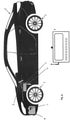
- the Fig. 1 represents a vehicle 1 equipped with tires comprising active TPMS sensors 2.
- This vehicle can be a passenger car, a van, a truck, a tractor and more generally, any vehicle moving on wheels with tires inflated with a gas.
- This vehicle can be thermal or electric propulsion.
- the sensors associated with each wheel typically comprise an electronic module comprising an electric battery, a printed circuit board with antennas or communication coils (for reception and transmission), an air pressure sensor, a temperature sensor , a rotation detection device or an accelerometer, a programmable controller and a memory for storing data such as the ID sensor ID. Given the encapsulation mode, it is generally not planned to change the battery.
- the sensors regularly transmit their information to an ECU 3 by a short-range wireless link, the ECU being equipped with an antenna 4.
- the ECU also communicates with the dashboard 5 to transmit signals representative of the state of certain vehicle equipment and possibly an alarm signal.
- the vehicle comprises at least one battery 6 which can be the rolling energy source in the case of an electric vehicle, or be charged by an alternator in the case of a vehicle fitted with a heat engine.
- Said battery is equipped with a control module 7 comprising a microcontroller connected to antennas or communication coils for the reception and transmission of data by a short-range wireless link.
- the control module further comprises a A/D converter to measure battery voltage, a temperature sensor and a memory to store data such as module ID.
- the control module 7 regularly transmits signals to the ECU 3 in order to communicate to it the voltage and the temperature of the battery 6.
- the module has a means for measuring the intensity of the current delivered by the battery.
- This measuring means can be a voltmeter measuring the voltage across the terminals of a very low resistance shunt, or a Hall effect sensor picking up the magnetic field generated by the passage of current on an output cable of the battery.
- the vehicle can be equipped with several batteries (which is generally the case for an electric vehicle, each battery has its own control module 7.
- a system for acquiring and analyzing data emitted by sensors on board vehicles comprises a tool 8 called a “TPMS tool” intended in particular to receive and process data originating from active TPMS sensors.
- This tool visible on the Fig. 1 is a portable test device typically comprising a battery, a processor, a memory, a user interface for displaying information and for entering commands, and a radio communication means.
- This means of communication comprises in particular an antenna emitting an electromagnetic field which in particular allows communication with TPMS sensors and possibly long-distance communication with a server via a network.
- the TPMS tool 8 is a portable test device comprising a housing having a front panel user interface which comprises a reference liquid crystal display (LCD) panel 10, several indicator lights 11, a push-button keypad (not visible in the figure, located below the screen 10) and an antenna 12.
- the antenna 12 is designed to communicate with the electronic control module ECU 3 and wirelessly with TPMS sensors 2 installed in the wheels of vehicle 1.
- the antenna 12 is a low frequency antenna, but other antennas for transmitting and receiving other frequencies can be used.
- the TPMS tool 8 also includes an autonomous power supply 13 such as a rechargeable battery, a controller 14 and a microprocessor 15 executing a software module stored in a memory 16.
- the memory is of the non-volatile type. in order to save data and possibly histories of the various measurements carried out.
- the TPMS tool also comprises at least one connector placed on the side of the device to communicate via a cable with the ECU 3 on board the vehicle, or any other device and in particular the computer network of the production line and a car garage.
- the TPMS tool has an optical scanner or a camera 17 intended to capture visual information present on equipment of the vehicle. Following the introduction of a command from the operator, the tool captures an image of the sticker present on the TPMS sensor, or of the label present on the battery. These inscriptions include a bar code which contains the identifier of the sensor in numerical form.
- the software module includes an OCR to analyze the captured image and to extract the characters. In this way, the TPMS tool can optically determine the characteristics of the various sensors and of the battery and in particular to know their identifiers.
- the scanner 17 can also be used to determine other characteristics, for example the registration number of the vehicle, or any identifying information relating to this vehicle.
- the TPMS tool has a means of radio communication (for example using Wifi) with a remote server, in order to transmit information relating to a vehicle to it.
- This device can be used at the end of the production line to indicate that the tires and the battery have been installed and to transmit data from the sensors.
- the Fig. 3 presents an example of a flowchart of the operations for acquiring and analyzing data emitted by sensors mounted or on board vehicles, according to the invention.
- the invention implements correlation and processing operations of said data by means of a monitoring tool which can be either an on-board unit, typically an on-board controller, or a unit used by an operator responsible for maintenance or repair, typically an appliance control laptop. These operations can also be divided between these two types of units.
- the means for correlating the data received by the monitoring tool consist in comparing all or part of said data received from the pressure sensors and those relating to the battery with reference values. The results of these correlations are used to control means for controlling and/or updating alert and/or monitoring functions of said monitoring tool, as illustrated by a few examples below.
- a first step 3.1 an operator uses his TPMS tool 8 and presents it successively in front of the sensors 2 and the battery control module 7.
- the operator enters the type of sensor ( tire sensor, battery sensor, ...) and possibly to their positions (right front tire, left front tire, spare tire, ...) which is in front of the tool.
- the TPMS tool 8 sends a wake-up signal to this sensor and the latter responds by transmitting its data, including its identifier.
- the operator uses the scanner 17 of the TPMS tool to pick up the characters affixed to the TPMS sensor or to the battery which is in front of the tool.
- the ECU then recovers a graphic identifier from the TPMS sensor or from the control module 7 and correlates it with the identifier transmitted by the radio link (step 3.2). If the identifiers are identical then the ECU saves the data by associating them with the position and the type of the sensor previously entered by the operator.
- the TPMS tool has collected all the data from the vehicle's sensors by associating them with their types and possibly their positions.
- the tool gathers this data into a packet (step 3.3) by associating each sensor ID with its type and position.
- This packet is in the form of a table, an example of which is shown below: ID Type Position A4B7B9B3B6 TPMS sensor Front left 9B6DC950AE TPMS sensor Front left 4794C4D2AB6 TPMS sensor Front left 897987DE3AB TPMS sensor Front left 765DF43ABE8 Battery sensor main battery
- step 3.4 the TPMS tool transmits this data packet via radio and cable to ECU 3. From this point on, ECU 3 is able to receive data from these sensors and determine what this data corresponds to.
- the sensors 2 and the module 7 regularly transmit their data to the ECU 3 which then checks whether these data correspond to normal operation.
- the ECU communicates with the dashboard 5 to transmit signals representative of the state of certain equipment of the vehicle, in particular the voltage of the battery, and possibly the pressure of the tires. If the measurements taken by the sensors deviate from a range of admissible values (“reference” values), the ECU sends an alarm signal to the instrument panel 5 (step 3.6) in order to warn the driver.
- the reliability of the information provided by the TPMS sensors, or their subsequent processing depends on a parameter linked to the battery, such as the nature, or the voltage of the battery
- the signal received from the battery makes it possible to detect or anticipate that the information received from the TMPS sensors is not reliable, or will lose its reliability.
- the ECU will send an appropriate warning signal, for example to the dashboard of the vehicle.
- This mode of use assumes that the battery control chain is less sensitive to the battery voltage than that of the TPMS sensors, or in other words that the measurement and/or interpretation of the battery parameter is systematically more reliable than those of the TPMS sensors.
- the ECU analyzes the variations of the data supplied by the TPMS sensors 2 in order to determine whether the vehicle 1 is moving. If so, and if the vehicle has a combustion engine, then the battery should be charging and have high voltage. If the ECU detects that the voltage has been decreasing for some time, then the alternator is not charging the battery. The ECU then sends a signal to the dashboard and possibly by radio a signal informing of this state.
- the ECU 3 analyzes the variations of the data supplied by the TPMS sensors 2 in order to determine whether the vehicle 1 is moving. If so, and if the vehicle has a combustion engine, then the battery should be charging and have high voltage. If the ECU detects that the voltage has been decreasing for some time, then the alternator is not charging the battery. The ECU then sends a signal to the dashboard and possibly by radio a signal informing of this state.
- the ECU 3 analyzes the variations of the data supplied by the TPMS sensors 2 in order to deduce that the vehicle is stopped, such a state is characterized by an absence of variation in the pressure of each of the four tires.
- the vehicle being stopped when the ECU detects a decrease in the voltage of the battery which reaches a value below a certain threshold then the ECU triggers an audible or visual alarm perceptible by the driver.
- This condition means that electrical devices have remained powered in the vehicle after it has been shut down, which may cause the battery to drain.
- the batteries come from many manufacturers and the 7 control modules inserted inside do not have the same communication protocol. In some cases, the ECU 3 is not immediately able to receive the signals.
- the battery control module 7 transmits information on its communication protocol. This protocol can include for example a certain data format transmitted at determined time intervals.
- the TPMS tool receives information on the communication protocol and, if necessary, communicates with a remote server in order to acquire this protocol. Once all the information allowing ECU 3 to receive data from the server is in the memory 16 of the TPMS tool, the latter transmits them to the ECU 3. In this way, the ECU is able to receive and analyze the data emitted by any type of sensor.
- step 3.2 the operator commands his TPMS tool 8 to scan the battery label.
- the information read then makes it possible to determine its characteristics in terms of electrical voltage and capacity.
- the TPMS tool also has the characteristics of the vehicle transmitted by the manufacturer. As a result, the tool is able to detect whether the installed battery complies with the manufacturer's specifications. This type of check is also possible at tire level. Knowing the type of vehicle, the TPMS tool is able to detect whether the characteristics of the tire (diameter, width, etc.) correspond to the manufacturer's recommendations and the tire pressure is within the range of recommended values. If the TPMS tool detects an anomaly, it displays on the screen both what is detected and what is recommended by the manufacturer.
- the vehicle has an intelligent charging alternator system, for example of the type supplying the battery with the quantity of electricity it needs, and stopping charging when it checks certain criteria by which it is considered to be sufficiently loaded.
- the ECU continuously processes the information transmitted by the control module 7 and calculates the quantity of electricity delivered by the battery. The ECU then commands the alternator to supply the battery with exactly the same amount of electricity. When the battery is again at 100%, then the ECU disconnects the alternator which then turns without generating current.
- the control logics of this type of "intelligent" alternator the absence of current in the windings no longer generates electromagnetic forces, thus relieving the heat engine of the vehicle and improving its performance. Other management logics exist or are possible.
- the method for controlling the connection and disconnection of the alternator from the battery will also take into account the information coming from the TPMS sensors of the vehicle to add an optimization factor in the battery charging control. So, for example, in the case of detection of a risk of tire failure, the system will favor or not the recharging of the battery to the detriment of the other factors conditioning the connection or the disconnection of the alternator.
- the combined consideration of the tire and battery control signals makes it possible to better detect and manage situations of multiple insecurity or cumulative failures. These situations are rare, but the performance of a security system, and of the procedures for checking its integrity and correct operation, presupposes taking into account these particularly problematic situations of accumulation of failures.
- the portable control devices according to the invention therefore make it possible to test and validate the proper functioning of these alert and control priority management procedures, and the correct impact of failure detection. tire(s) by the TPMS system on the control of the "intelligent alternator".
Landscapes
- Engineering & Computer Science (AREA)
- Power Engineering (AREA)
- Mechanical Engineering (AREA)
- Life Sciences & Earth Sciences (AREA)
- Sustainable Development (AREA)
- Sustainable Energy (AREA)
- Transportation (AREA)
- Physics & Mathematics (AREA)
- General Physics & Mathematics (AREA)
- Arrangements For Transmission Of Measured Signals (AREA)
Claims (15)
- System zur Verarbeitung von Daten, die von Drucksensoren (2) der auf einem Fahrzeug (1) montierten Reifen ausgesendet werden, von der Art mit einem Monitoring-Tool, das Daten physikalischer Größen empfängt, die von TPMS-Sensoren an jedem Reifen des Fahrzeugs gemessen werden,dadurch gekennzeichnet, dass das Monitoring-Tool ebenfalls Daten über die Batterie (6) des Fahrzeugs empfängt,wobei das Monitoring-Tool ferner Korrelationsmittel von Daten im Datensatz aufweist, der durch die von den Drucksensoren empfangenen und durch die auf die Batterie bezogenen Daten sowie durch Referenzwerte gebildet ist, wobei die Korrelationsmittel Mittel zur Steuerung und/oder zur Aktualisierung von Alarm- und/oder Monitoringfunktionen des Monitoring-Tools steuern.
- Datenverarbeitungssystem nach Anspruch 1, dadurch gekennzeichnet, dass das Monitoring-Tool zu der Gruppe gehört, die ein tragbares Testgerät (8) mit einer Benutzerschnittstelle und einen in dem Fahrzeug befindlichen Onboard-Controller (3) umfasst.
- Datenverarbeitungssystem nach einem beliebigen der Ansprüche 1 und 2, dadurch gekennzeichnet, dass die auf die Batterie (6) des Fahrzeugs bezogenen Daten durch Daten physikalischer Größen bezüglich der Batterie gebildet sind, die von einem Testsensor (7) der Batterie gemessen werden.
- Datenverarbeitungssystem nach einem beliebigen der Ansprüche 1 bis 3, dadurch gekennzeichnet, dass die Mittel zur Steuerung und/oder Aktualisierung von Monitoringfunktionen des Monitoring-Tools zu der Gruppe gehören, die umfasst:- Mittel, die es ermöglichen, ein Fahrzeug besser zu identifizieren;- Mittel, die es ermöglichen, Protokolle zur Abfrage der Sensoren und/oder der Referenzwerte herunterzuladen und/oder zu aktualisieren;- Mittel, um die Bedienperson besser zu unterstützen, indem ihr Empfehlungen und/oder Alarme adressiert werden.
- Datenverarbeitungssystem nach einem beliebigen der Ansprüche 1 bis 4, dadurch gekennzeichnet, dass das Monitoring-Tool ein tragbares Testgerät (8) mit einer Benutzerschnittstelle ist, das dazu bestimmt ist, mit einem in dem Fahrzeug befindlichen Onboard-Controller (3) zusammenzuwirken, der periodisch Daten physikalischer Größen empfängt, die von TPMS-Sensoren an jedem Reifen des Fahrzeugs gemessen werden,
und dass der Controller (3) Daten physikalischer Größen speichert, die einerseits an jedem Reifen und andererseits an der Batterie des Fahrzeugs gemessen werden, und diese in einem vorbestimmten Format in Form einer Historie an das tragbare Testgerät überträgt. - Datenverarbeitungssystem nach Anspruch 1, bei dem das Monitoring-Tool ein in dem Fahrzeug befindlicher Onboard-Controller (3) ist, der periodisch Daten physikalischer Größen empfängt, die von TPMS-Sensoren an jedem Reifen des Fahrzeugs gemessen werden,und bei dem das Fahrzeug (1) einen Verbrennungsmotor und einen Wechselstromgenerator aufweist, der die Batterie auflädt, während das Fahrzeug fährt,dadurch gekennzeichnet, dass der Onboard-Controller (3) Mittel aufweist, um durch Analyse der relativen Veränderungen des Drucks aller oder eines Teils der vier Reifen zu folgern, dass das Fahrzeug fährt, und dass er Mittel zum Auslösen eines von dem Fahrer wahrnehmbaren akustischen oder optischen Alarms umfasst, wenn der Onboard-Controller (3) eine Verringerung der Spannung der Batterie erkennt, während das Fahrzeug fährt.
- Datenverarbeitungssystem nach Anspruch 6, dadurch gekennzeichnet, dass der Onboard-Controller (3) durch Erkennen einer ausbleibenden Veränderung des Drucks aller oder eines Teils aller vier Reifen folgert, dass das Fahrzeug steht, und dass er Mittel zum Auslösen eines von dem Fahrer wahrnehmbaren akustischen oder optischen Alarms umfasst, wenn der Onboard-Controller (3) einen Abfall der Spannung der Batterie unter einen bestimmten Schwellenwert erkennt, während das Fahrzeug steht.
- Datenverarbeitungssystem nach einem beliebigen der vorhergehenden Ansprüche, dadurch gekennzeichnet, dass das tragbare Gerät über eine Kamera verfügt, die dazu bestimmt ist, Bilder der TPMS-Drucksensoren und der Batterie aufzunehmen, um daraus einen Satz erster Daten zu extrahieren, darunter eine sogenannte "erste" Kennung, wobei das Gerät ferner über ein Mittel zum Senden eines Wecksignals an die Sensoren verfügt, um per Funk einen Satz zweiter Daten, darunter eine sogenannte "zweite" Kennung, zu erhalten, wobei die Gleichheit zwischen der ersten und der zweiten Kennung das Speichern einer Zuordnung zwischen dieser Kennung und einer Information auslöst, die für die Position und den Typ des vor dem Tool angeordneten Sensors repräsentativ ist.
- Datenverarbeitungssystem nach einem beliebigen der Ansprüche 6 und 7, dadurch gekennzeichnet, dass der Onboard-Controller die von mindestens einem Sensor gesendeten Daten in bestimmten Zeitabständen überträgt, so dass an dem Armaturenbrett des Fahrzeugs eine für diese Daten repräsentative Information angezeigt wird.
- Datenverarbeitungssystem nach einem beliebigen der vorhergehenden Ansprüche, dadurch gekennzeichnet, dass das tragbare Testgerät (8) von mindestens einem Sensor (2,7) eine das Kommunikationsprotokoll des Sensors kennzeichnende Information empfängt und dem Onboard-Controller einen Datensatz übermittelt, der es dem Controller ermöglicht, die von diesem Sensor gesendeten Daten zu erfassen.
- Verfahren zum Testen und Prüfen der Sicherheit eines Fahrzeugs, das in einem Datenverarbeitungssystem nach einem beliebigen der Ansprüche 6 bis 10 implementiert ist, dadurch gekennzeichnet, dass es alle oder einen Teil der folgenden Schritte umfasst:- Inverbindungsetzen des tragbaren Geräts (8) mit dem Onboard-Controller (3);- Senden einer Anfrage von dem tragbaren Gerät an den Onboard-Controller (3), um die Übertragung einer ersten Reihe von Daten zu erreichen, die sowohl von den TPMS-Sensoren als auch von dem Batteriesensor stammen;- in Abhängigkeit von einer Verarbeitung der ersten Datenreihe in dem tragbaren Gerät kommuniziert das tragbare Gerät eventuell ein zweites Mal mit dem On-board-Controller (3), um die Übertragung einer zweiten Reihe von Daten zu erreichen, die von den TPMS-Sensoren und/oder von dem Batteriesensor stammen.
- Verfahren zum Testen und Prüfen der Sicherheit eines Fahrzeugs, das in einem Datenverarbeitungssystem nach einem beliebigen der Ansprüche 6 bis 10 implementiert ist, dadurch gekennzeichnet, dass es alle oder einen Teil der folgenden Schritte umfasst:- Inverbindungsetzen des tragbaren Testgeräts (8) mit dem Onboard-Controller (3);- Überprüfen, je nach dem durchzuführenden Testverfahren, ob der Motor des Fahrzeugs steht oder läuft;- Simulieren des Rollens des Fahrzeugs auf einem geeigneten Prüfstand;- Steuerung des Onboard-Controllers (3) durch das tragbare Testgerät (8), um mindestens eine vorbestimmte Testphase gemäß einem Protokoll für den Test der korrekten Funktionsweise des Datenverarbeitungssystems nach einem beliebigen der Ansprüche 1 bis 6 durchzuführen;- Rückgewinnung durch das tragbare Gerät aus dem Onboard-Controller (3) von mindestens einer ersten Reihe von sowohl von den TPMS-Sensoren als auch von dem Batteriesensor stammenden Daten, wie sie während der vorbestimmten Testphase erzeugt wurden.
- Verfahren zum Testen und Prüfen der Sicherheit eines Fahrzeugs, das in einem Datenverarbeitungssystem nach einem beliebigen der Ansprüche 1 bis 10 implementiert ist und das auf ein Fahrzeug (1) angewendet wird, in dem ein Batterieladesystem in Abhängigkeit von ersten Daten über den Ladezustand der Batterie angeschlossen und getrennt wird, dadurch gekennzeichnet, dass das Batterieladesystem ebenfalls anhand von zweiten, von dem Onboard-Controller (3) bereitgestellten und auf Daten physikalischer Größen, die am jeweiligen Reifen des Fahrzeugs gemessen werden, bezogenen Daten gesteuert wird.
- Tragbares Testgerät, das in einem Datenverarbeitungssystem nach einem beliebigen der Ansprüche 1 bis 10 und/oder das ein Kontrollverfahren nach einem beliebigen der Ansprüche 11 bis 13 umsetzt, einsetzbar ist.
- Onboard-Controller, der in einem Datenverarbeitungssystem nach einem beliebigen der Ansprüche 1 bis 10 und/oder das ein Kontrollverfahren nach einem beliebigen der Ansprüche 11 bis 13 umsetzt, einsetzbar ist.
Applications Claiming Priority (1)
| Application Number | Priority Date | Filing Date | Title |
|---|---|---|---|
| FR1761462A FR3074094B1 (fr) | 2017-11-30 | 2017-11-30 | Systeme d'acquisition et d'analyse de donnees emises par des capteurs embarques dans des vehicules, procede et appareil portable de controle associes. |
Publications (2)
| Publication Number | Publication Date |
|---|---|
| EP3492290A1 EP3492290A1 (de) | 2019-06-05 |
| EP3492290B1 true EP3492290B1 (de) | 2022-02-16 |
Family
ID=62143241
Family Applications (1)
| Application Number | Title | Priority Date | Filing Date |
|---|---|---|---|
| EP18209657.8A Active EP3492290B1 (de) | 2017-11-30 | 2018-11-30 | Erfassungs- und analysesystem von daten, die von in fahrzeugen eingebauten sensoren ausgesandt werden, entsprechendes verfahren, tragbares kontrollgerät und entsprechende eingebaute kontrolleinheit |
Country Status (2)
| Country | Link |
|---|---|
| EP (1) | EP3492290B1 (de) |
| FR (1) | FR3074094B1 (de) |
Families Citing this family (2)
| Publication number | Priority date | Publication date | Assignee | Title |
|---|---|---|---|---|
| CN110910609A (zh) * | 2019-11-21 | 2020-03-24 | 安徽江淮汽车集团股份有限公司 | 用于儿童遗忘系统的测试系统及方法 |
| CN114401286B (zh) * | 2021-12-21 | 2023-06-30 | 江西五十铃汽车有限公司 | 基于车载终端的数据上传方法、系统、存储介质及车辆 |
Family Cites Families (3)
| Publication number | Priority date | Publication date | Assignee | Title |
|---|---|---|---|---|
| WO2013063061A1 (en) * | 2011-10-26 | 2013-05-02 | Ateq Corporation | Universal tire pressure monitoring system tool and methods |
| US20140012459A1 (en) * | 2012-07-05 | 2014-01-09 | BlueRadios, Inc. | System And Method To Instrument And Gather Three Dimensional (3-D) Vehicle Tracking And Information |
| US9581654B2 (en) * | 2013-02-12 | 2017-02-28 | Johnson Controls Technology Company | Vehicle battery monitoring system |
-
2017
- 2017-11-30 FR FR1761462A patent/FR3074094B1/fr active Active
-
2018
- 2018-11-30 EP EP18209657.8A patent/EP3492290B1/de active Active
Also Published As
| Publication number | Publication date |
|---|---|
| FR3074094B1 (fr) | 2019-11-22 |
| EP3492290A1 (de) | 2019-06-05 |
| FR3074094A1 (fr) | 2019-05-31 |
Similar Documents
| Publication | Publication Date | Title |
|---|---|---|
| EP3923251B1 (de) | Überwachung von spannungsmessungen für eine fahrzeugbatterie | |
| EP3814791B1 (de) | System und verfahren zur überwachung des kraftfahrzeugbatterieverschleisses | |
| US20120029852A1 (en) | Battery monitor system attached to a vehicle wiring harness | |
| US8311507B2 (en) | Telematics systems and related connection methods for establishing wireless communication links | |
| KR102471498B1 (ko) | 차량을 진단하는 전자 장치 및 방법 | |
| US10255782B1 (en) | Vehicle flood detection | |
| US20210166502A1 (en) | Using vehicle electrical system monitored values | |
| CN101903786B (zh) | 基于远程信息处理的用于车队的电池寄生负载确认的方法和系统 | |
| US20080164846A1 (en) | Apparatus and method to update and maintain a tire pressure monitoring tool | |
| FR2829426A1 (fr) | Procede d'association de dispositifs de mesure de pression de pneumatique d'un vehicule automobile a des positions de roue et dispositif de mesure de la pression de pneumatique | |
| US20130106596A1 (en) | Universal tire pressure monitoring system tool and methods | |
| CN109910781A (zh) | 用于监控车辆电力系统的系统和方法 | |
| RU2760756C2 (ru) | Способ оценки времени в пути транспортного средства на основании определения состояния транспортного средства | |
| FR3074094B1 (fr) | Systeme d'acquisition et d'analyse de donnees emises par des capteurs embarques dans des vehicules, procede et appareil portable de controle associes. | |
| WO2016065320A1 (en) | System for performing vehicle diagnostic and prognostic analysis | |
| EP0794074B1 (de) | Verfahren zur Auswertung von Druck- und Temperaturmessung in einer Reifendruck-Überwachungseinrichtung | |
| WO2012001290A2 (fr) | Transmission de donnees de fonctionnement d'une batterie d'alimentation d'un moteur d'entrainement d'un vehicule automobile | |
| EP1589490B1 (de) | Steuergerät und Datenübertragungsverfahren | |
| EP3507110B1 (de) | System zum lesen von sensoren zur überwachung von kraftfahrzeugen | |
| KR20130008702A (ko) | 차량 모니터링 장치 | |
| WO2018042112A1 (fr) | Stratégie de remise en service d'une unité-roue déclarée détachée dans un système tpms de contrôle de la pression des pneus d'un véhicule automobile | |
| US10739204B1 (en) | Bearing temperature sensing system | |
| EP3255442B1 (de) | Diagnosemethode einer anordnung von akkubatterien, die in einer fahrzeugflotte verteilt sind | |
| EP3492896B1 (de) | Verarbeitungssystem von daten, die von messvorrichtungen des reifenzustands ausgegeben werden, und entsprechendes tragbares gerät | |
| US12436200B2 (en) | Battery load test in agricultural utility vehicle |
Legal Events
| Date | Code | Title | Description |
|---|---|---|---|
| PUAI | Public reference made under article 153(3) epc to a published international application that has entered the european phase |
Free format text: ORIGINAL CODE: 0009012 |
|
| STAA | Information on the status of an ep patent application or granted ep patent |
Free format text: STATUS: THE APPLICATION HAS BEEN PUBLISHED |
|
| AK | Designated contracting states |
Kind code of ref document: A1 Designated state(s): AL AT BE BG CH CY CZ DE DK EE ES FI FR GB GR HR HU IE IS IT LI LT LU LV MC MK MT NL NO PL PT RO RS SE SI SK SM TR |
|
| AX | Request for extension of the european patent |
Extension state: BA ME |
|
| STAA | Information on the status of an ep patent application or granted ep patent |
Free format text: STATUS: REQUEST FOR EXAMINATION WAS MADE |
|
| 17P | Request for examination filed |
Effective date: 20190820 |
|
| RBV | Designated contracting states (corrected) |
Designated state(s): AL AT BE BG CH CY CZ DE DK EE ES FI FR GB GR HR HU IE IS IT LI LT LU LV MC MK MT NL NO PL PT RO RS SE SI SK SM TR |
|
| GRAP | Despatch of communication of intention to grant a patent |
Free format text: ORIGINAL CODE: EPIDOSNIGR1 |
|
| STAA | Information on the status of an ep patent application or granted ep patent |
Free format text: STATUS: GRANT OF PATENT IS INTENDED |
|
| RIC1 | Information provided on ipc code assigned before grant |
Ipc: B60L 13/00 20060101ALI20210909BHEP Ipc: B60L 8/00 20060101ALI20210909BHEP Ipc: G07C 5/00 20060101ALI20210909BHEP Ipc: G01R 31/36 20200101ALI20210909BHEP Ipc: B60C 23/04 20060101AFI20210909BHEP |
|
| GRAJ | Information related to disapproval of communication of intention to grant by the applicant or resumption of examination proceedings by the epo deleted |
Free format text: ORIGINAL CODE: EPIDOSDIGR1 |
|
| GRAP | Despatch of communication of intention to grant a patent |
Free format text: ORIGINAL CODE: EPIDOSNIGR1 |
|
| INTG | Intention to grant announced |
Effective date: 20211011 |
|
| INTG | Intention to grant announced |
Effective date: 20211027 |
|
| GRAS | Grant fee paid |
Free format text: ORIGINAL CODE: EPIDOSNIGR3 |
|
| GRAA | (expected) grant |
Free format text: ORIGINAL CODE: 0009210 |
|
| STAA | Information on the status of an ep patent application or granted ep patent |
Free format text: STATUS: THE PATENT HAS BEEN GRANTED |
|
| AK | Designated contracting states |
Kind code of ref document: B1 Designated state(s): AL AT BE BG CH CY CZ DE DK EE ES FI FR GB GR HR HU IE IS IT LI LT LU LV MC MK MT NL NO PL PT RO RS SE SI SK SM TR |
|
| REG | Reference to a national code |
Ref country code: GB Ref legal event code: FG4D Free format text: NOT ENGLISH |
|
| REG | Reference to a national code |
Ref country code: CH Ref legal event code: EP |
|
| REG | Reference to a national code |
Ref country code: DE Ref legal event code: R096 Ref document number: 602018030865 Country of ref document: DE |
|
| REG | Reference to a national code |
Ref country code: AT Ref legal event code: REF Ref document number: 1468671 Country of ref document: AT Kind code of ref document: T Effective date: 20220315 |
|
| REG | Reference to a national code |
Ref country code: IE Ref legal event code: FG4D Free format text: LANGUAGE OF EP DOCUMENT: FRENCH |
|
| REG | Reference to a national code |
Ref country code: LT Ref legal event code: MG9D |
|
| REG | Reference to a national code |
Ref country code: NL Ref legal event code: MP Effective date: 20220216 |
|
| REG | Reference to a national code |
Ref country code: AT Ref legal event code: MK05 Ref document number: 1468671 Country of ref document: AT Kind code of ref document: T Effective date: 20220216 |
|
| PG25 | Lapsed in a contracting state [announced via postgrant information from national office to epo] |
Ref country code: SE Free format text: LAPSE BECAUSE OF FAILURE TO SUBMIT A TRANSLATION OF THE DESCRIPTION OR TO PAY THE FEE WITHIN THE PRESCRIBED TIME-LIMIT Effective date: 20220216 Ref country code: RS Free format text: LAPSE BECAUSE OF FAILURE TO SUBMIT A TRANSLATION OF THE DESCRIPTION OR TO PAY THE FEE WITHIN THE PRESCRIBED TIME-LIMIT Effective date: 20220216 Ref country code: PT Free format text: LAPSE BECAUSE OF FAILURE TO SUBMIT A TRANSLATION OF THE DESCRIPTION OR TO PAY THE FEE WITHIN THE PRESCRIBED TIME-LIMIT Effective date: 20220616 Ref country code: NO Free format text: LAPSE BECAUSE OF FAILURE TO SUBMIT A TRANSLATION OF THE DESCRIPTION OR TO PAY THE FEE WITHIN THE PRESCRIBED TIME-LIMIT Effective date: 20220516 Ref country code: NL Free format text: LAPSE BECAUSE OF FAILURE TO SUBMIT A TRANSLATION OF THE DESCRIPTION OR TO PAY THE FEE WITHIN THE PRESCRIBED TIME-LIMIT Effective date: 20220216 Ref country code: LT Free format text: LAPSE BECAUSE OF FAILURE TO SUBMIT A TRANSLATION OF THE DESCRIPTION OR TO PAY THE FEE WITHIN THE PRESCRIBED TIME-LIMIT Effective date: 20220216 Ref country code: HR Free format text: LAPSE BECAUSE OF FAILURE TO SUBMIT A TRANSLATION OF THE DESCRIPTION OR TO PAY THE FEE WITHIN THE PRESCRIBED TIME-LIMIT Effective date: 20220216 Ref country code: ES Free format text: LAPSE BECAUSE OF FAILURE TO SUBMIT A TRANSLATION OF THE DESCRIPTION OR TO PAY THE FEE WITHIN THE PRESCRIBED TIME-LIMIT Effective date: 20220216 Ref country code: BG Free format text: LAPSE BECAUSE OF FAILURE TO SUBMIT A TRANSLATION OF THE DESCRIPTION OR TO PAY THE FEE WITHIN THE PRESCRIBED TIME-LIMIT Effective date: 20220516 |
|
| PG25 | Lapsed in a contracting state [announced via postgrant information from national office to epo] |
Ref country code: PL Free format text: LAPSE BECAUSE OF FAILURE TO SUBMIT A TRANSLATION OF THE DESCRIPTION OR TO PAY THE FEE WITHIN THE PRESCRIBED TIME-LIMIT Effective date: 20220216 Ref country code: LV Free format text: LAPSE BECAUSE OF FAILURE TO SUBMIT A TRANSLATION OF THE DESCRIPTION OR TO PAY THE FEE WITHIN THE PRESCRIBED TIME-LIMIT Effective date: 20220216 Ref country code: GR Free format text: LAPSE BECAUSE OF FAILURE TO SUBMIT A TRANSLATION OF THE DESCRIPTION OR TO PAY THE FEE WITHIN THE PRESCRIBED TIME-LIMIT Effective date: 20220517 Ref country code: FI Free format text: LAPSE BECAUSE OF FAILURE TO SUBMIT A TRANSLATION OF THE DESCRIPTION OR TO PAY THE FEE WITHIN THE PRESCRIBED TIME-LIMIT Effective date: 20220216 Ref country code: AT Free format text: LAPSE BECAUSE OF FAILURE TO SUBMIT A TRANSLATION OF THE DESCRIPTION OR TO PAY THE FEE WITHIN THE PRESCRIBED TIME-LIMIT Effective date: 20220216 |
|
| PG25 | Lapsed in a contracting state [announced via postgrant information from national office to epo] |
Ref country code: IS Free format text: LAPSE BECAUSE OF FAILURE TO SUBMIT A TRANSLATION OF THE DESCRIPTION OR TO PAY THE FEE WITHIN THE PRESCRIBED TIME-LIMIT Effective date: 20220617 |
|
| PG25 | Lapsed in a contracting state [announced via postgrant information from national office to epo] |
Ref country code: SM Free format text: LAPSE BECAUSE OF FAILURE TO SUBMIT A TRANSLATION OF THE DESCRIPTION OR TO PAY THE FEE WITHIN THE PRESCRIBED TIME-LIMIT Effective date: 20220216 Ref country code: SK Free format text: LAPSE BECAUSE OF FAILURE TO SUBMIT A TRANSLATION OF THE DESCRIPTION OR TO PAY THE FEE WITHIN THE PRESCRIBED TIME-LIMIT Effective date: 20220216 Ref country code: RO Free format text: LAPSE BECAUSE OF FAILURE TO SUBMIT A TRANSLATION OF THE DESCRIPTION OR TO PAY THE FEE WITHIN THE PRESCRIBED TIME-LIMIT Effective date: 20220216 Ref country code: EE Free format text: LAPSE BECAUSE OF FAILURE TO SUBMIT A TRANSLATION OF THE DESCRIPTION OR TO PAY THE FEE WITHIN THE PRESCRIBED TIME-LIMIT Effective date: 20220216 Ref country code: DK Free format text: LAPSE BECAUSE OF FAILURE TO SUBMIT A TRANSLATION OF THE DESCRIPTION OR TO PAY THE FEE WITHIN THE PRESCRIBED TIME-LIMIT Effective date: 20220216 Ref country code: CZ Free format text: LAPSE BECAUSE OF FAILURE TO SUBMIT A TRANSLATION OF THE DESCRIPTION OR TO PAY THE FEE WITHIN THE PRESCRIBED TIME-LIMIT Effective date: 20220216 |
|
| REG | Reference to a national code |
Ref country code: DE Ref legal event code: R097 Ref document number: 602018030865 Country of ref document: DE |
|
| PG25 | Lapsed in a contracting state [announced via postgrant information from national office to epo] |
Ref country code: AL Free format text: LAPSE BECAUSE OF FAILURE TO SUBMIT A TRANSLATION OF THE DESCRIPTION OR TO PAY THE FEE WITHIN THE PRESCRIBED TIME-LIMIT Effective date: 20220216 |
|
| PLBE | No opposition filed within time limit |
Free format text: ORIGINAL CODE: 0009261 |
|
| STAA | Information on the status of an ep patent application or granted ep patent |
Free format text: STATUS: NO OPPOSITION FILED WITHIN TIME LIMIT |
|
| 26N | No opposition filed |
Effective date: 20221117 |
|
| PG25 | Lapsed in a contracting state [announced via postgrant information from national office to epo] |
Ref country code: SI Free format text: LAPSE BECAUSE OF FAILURE TO SUBMIT A TRANSLATION OF THE DESCRIPTION OR TO PAY THE FEE WITHIN THE PRESCRIBED TIME-LIMIT Effective date: 20220216 |
|
| PG25 | Lapsed in a contracting state [announced via postgrant information from national office to epo] |
Ref country code: MC Free format text: LAPSE BECAUSE OF FAILURE TO SUBMIT A TRANSLATION OF THE DESCRIPTION OR TO PAY THE FEE WITHIN THE PRESCRIBED TIME-LIMIT Effective date: 20220216 |
|
| REG | Reference to a national code |
Ref country code: CH Ref legal event code: PL |
|
| P01 | Opt-out of the competence of the unified patent court (upc) registered |
Effective date: 20230527 |
|
| REG | Reference to a national code |
Ref country code: BE Ref legal event code: MM Effective date: 20221130 |
|
| PG25 | Lapsed in a contracting state [announced via postgrant information from national office to epo] |
Ref country code: LI Free format text: LAPSE BECAUSE OF NON-PAYMENT OF DUE FEES Effective date: 20221130 Ref country code: IT Free format text: LAPSE BECAUSE OF FAILURE TO SUBMIT A TRANSLATION OF THE DESCRIPTION OR TO PAY THE FEE WITHIN THE PRESCRIBED TIME-LIMIT Effective date: 20220216 Ref country code: CH Free format text: LAPSE BECAUSE OF NON-PAYMENT OF DUE FEES Effective date: 20221130 |
|
| PG25 | Lapsed in a contracting state [announced via postgrant information from national office to epo] |
Ref country code: LU Free format text: LAPSE BECAUSE OF NON-PAYMENT OF DUE FEES Effective date: 20221130 |
|
| PG25 | Lapsed in a contracting state [announced via postgrant information from national office to epo] |
Ref country code: IE Free format text: LAPSE BECAUSE OF NON-PAYMENT OF DUE FEES Effective date: 20221130 |
|
| PG25 | Lapsed in a contracting state [announced via postgrant information from national office to epo] |
Ref country code: BE Free format text: LAPSE BECAUSE OF NON-PAYMENT OF DUE FEES Effective date: 20221130 |
|
| PG25 | Lapsed in a contracting state [announced via postgrant information from national office to epo] |
Ref country code: HU Free format text: LAPSE BECAUSE OF FAILURE TO SUBMIT A TRANSLATION OF THE DESCRIPTION OR TO PAY THE FEE WITHIN THE PRESCRIBED TIME-LIMIT; INVALID AB INITIO Effective date: 20181130 |
|
| PG25 | Lapsed in a contracting state [announced via postgrant information from national office to epo] |
Ref country code: CY Free format text: LAPSE BECAUSE OF FAILURE TO SUBMIT A TRANSLATION OF THE DESCRIPTION OR TO PAY THE FEE WITHIN THE PRESCRIBED TIME-LIMIT Effective date: 20220216 |
|
| PG25 | Lapsed in a contracting state [announced via postgrant information from national office to epo] |
Ref country code: MK Free format text: LAPSE BECAUSE OF FAILURE TO SUBMIT A TRANSLATION OF THE DESCRIPTION OR TO PAY THE FEE WITHIN THE PRESCRIBED TIME-LIMIT Effective date: 20220216 |
|
| PG25 | Lapsed in a contracting state [announced via postgrant information from national office to epo] |
Ref country code: MT Free format text: LAPSE BECAUSE OF FAILURE TO SUBMIT A TRANSLATION OF THE DESCRIPTION OR TO PAY THE FEE WITHIN THE PRESCRIBED TIME-LIMIT Effective date: 20220216 |
|
| PG25 | Lapsed in a contracting state [announced via postgrant information from national office to epo] |
Ref country code: TR Free format text: LAPSE BECAUSE OF FAILURE TO SUBMIT A TRANSLATION OF THE DESCRIPTION OR TO PAY THE FEE WITHIN THE PRESCRIBED TIME-LIMIT Effective date: 20220216 |
|
| PGFP | Annual fee paid to national office [announced via postgrant information from national office to epo] |
Ref country code: DE Payment date: 20251117 Year of fee payment: 8 |
|
| PGFP | Annual fee paid to national office [announced via postgrant information from national office to epo] |
Ref country code: GB Payment date: 20251126 Year of fee payment: 8 |
|
| PGFP | Annual fee paid to national office [announced via postgrant information from national office to epo] |
Ref country code: FR Payment date: 20251126 Year of fee payment: 8 |