EP3492199A1 - Microstructure refinement methods by melt pool stirring for additive manufactured materials - Google Patents
Microstructure refinement methods by melt pool stirring for additive manufactured materials Download PDFInfo
- Publication number
- EP3492199A1 EP3492199A1 EP18198960.9A EP18198960A EP3492199A1 EP 3492199 A1 EP3492199 A1 EP 3492199A1 EP 18198960 A EP18198960 A EP 18198960A EP 3492199 A1 EP3492199 A1 EP 3492199A1
- Authority
- EP
- European Patent Office
- Prior art keywords
- layer
- metallic material
- molten state
- applying
- solid
- Prior art date
- Legal status (The legal status is an assumption and is not a legal conclusion. Google has not performed a legal analysis and makes no representation as to the accuracy of the status listed.)
- Granted
Links
Images



Classifications
-
- B—PERFORMING OPERATIONS; TRANSPORTING
- B22—CASTING; POWDER METALLURGY
- B22F—WORKING METALLIC POWDER; MANUFACTURE OF ARTICLES FROM METALLIC POWDER; MAKING METALLIC POWDER; APPARATUS OR DEVICES SPECIALLY ADAPTED FOR METALLIC POWDER
- B22F7/00—Manufacture of composite layers, workpieces, or articles, comprising metallic powder, by sintering the powder, with or without compacting wherein at least one part is obtained by sintering or compression
- B22F7/002—Manufacture of composite layers, workpieces, or articles, comprising metallic powder, by sintering the powder, with or without compacting wherein at least one part is obtained by sintering or compression of porous nature
-
- B—PERFORMING OPERATIONS; TRANSPORTING
- B22—CASTING; POWDER METALLURGY
- B22F—WORKING METALLIC POWDER; MANUFACTURE OF ARTICLES FROM METALLIC POWDER; MAKING METALLIC POWDER; APPARATUS OR DEVICES SPECIALLY ADAPTED FOR METALLIC POWDER
- B22F10/00—Additive manufacturing of workpieces or articles from metallic powder
-
- B—PERFORMING OPERATIONS; TRANSPORTING
- B22—CASTING; POWDER METALLURGY
- B22F—WORKING METALLIC POWDER; MANUFACTURE OF ARTICLES FROM METALLIC POWDER; MAKING METALLIC POWDER; APPARATUS OR DEVICES SPECIALLY ADAPTED FOR METALLIC POWDER
- B22F10/00—Additive manufacturing of workpieces or articles from metallic powder
- B22F10/20—Direct sintering or melting
-
- B—PERFORMING OPERATIONS; TRANSPORTING
- B22—CASTING; POWDER METALLURGY
- B22F—WORKING METALLIC POWDER; MANUFACTURE OF ARTICLES FROM METALLIC POWDER; MAKING METALLIC POWDER; APPARATUS OR DEVICES SPECIALLY ADAPTED FOR METALLIC POWDER
- B22F12/00—Apparatus or devices specially adapted for additive manufacturing; Auxiliary means for additive manufacturing; Combinations of additive manufacturing apparatus or devices with other processing apparatus or devices
- B22F12/40—Radiation means
- B22F12/41—Radiation means characterised by the type, e.g. laser or electron beam
-
- B—PERFORMING OPERATIONS; TRANSPORTING
- B22—CASTING; POWDER METALLURGY
- B22F—WORKING METALLIC POWDER; MANUFACTURE OF ARTICLES FROM METALLIC POWDER; MAKING METALLIC POWDER; APPARATUS OR DEVICES SPECIALLY ADAPTED FOR METALLIC POWDER
- B22F12/00—Apparatus or devices specially adapted for additive manufacturing; Auxiliary means for additive manufacturing; Combinations of additive manufacturing apparatus or devices with other processing apparatus or devices
- B22F12/80—Plants, production lines or modules
- B22F12/88—Handling of additively manufactured products, e.g. by robots
-
- B—PERFORMING OPERATIONS; TRANSPORTING
- B22—CASTING; POWDER METALLURGY
- B22F—WORKING METALLIC POWDER; MANUFACTURE OF ARTICLES FROM METALLIC POWDER; MAKING METALLIC POWDER; APPARATUS OR DEVICES SPECIALLY ADAPTED FOR METALLIC POWDER
- B22F3/00—Manufacture of workpieces or articles from metallic powder characterised by the manner of compacting or sintering; Apparatus specially adapted therefor ; Presses and furnaces
- B22F3/24—After-treatment of workpieces or articles
-
- B—PERFORMING OPERATIONS; TRANSPORTING
- B23—MACHINE TOOLS; METAL-WORKING NOT OTHERWISE PROVIDED FOR
- B23K—SOLDERING OR UNSOLDERING; WELDING; CLADDING OR PLATING BY SOLDERING OR WELDING; CUTTING BY APPLYING HEAT LOCALLY, e.g. FLAME CUTTING; WORKING BY LASER BEAM
- B23K26/00—Working by laser beam, e.g. welding, cutting or boring
- B23K26/34—Laser welding for purposes other than joining
- B23K26/342—Build-up welding
-
- B—PERFORMING OPERATIONS; TRANSPORTING
- B23—MACHINE TOOLS; METAL-WORKING NOT OTHERWISE PROVIDED FOR
- B23P—METAL-WORKING NOT OTHERWISE PROVIDED FOR; COMBINED OPERATIONS; UNIVERSAL MACHINE TOOLS
- B23P9/00—Treating or finishing surfaces mechanically, with or without calibrating, primarily to resist wear or impact, e.g. smoothing or roughening turbine blades or bearings; Features of such surfaces not otherwise provided for, their treatment being unspecified
-
- B—PERFORMING OPERATIONS; TRANSPORTING
- B33—ADDITIVE MANUFACTURING TECHNOLOGY
- B33Y—ADDITIVE MANUFACTURING, i.e. MANUFACTURING OF THREE-DIMENSIONAL [3D] OBJECTS BY ADDITIVE DEPOSITION, ADDITIVE AGGLOMERATION OR ADDITIVE LAYERING, e.g. BY 3D PRINTING, STEREOLITHOGRAPHY OR SELECTIVE LASER SINTERING
- B33Y10/00—Processes of additive manufacturing
-
- B—PERFORMING OPERATIONS; TRANSPORTING
- B33—ADDITIVE MANUFACTURING TECHNOLOGY
- B33Y—ADDITIVE MANUFACTURING, i.e. MANUFACTURING OF THREE-DIMENSIONAL [3D] OBJECTS BY ADDITIVE DEPOSITION, ADDITIVE AGGLOMERATION OR ADDITIVE LAYERING, e.g. BY 3D PRINTING, STEREOLITHOGRAPHY OR SELECTIVE LASER SINTERING
- B33Y30/00—Apparatus for additive manufacturing; Details thereof or accessories therefor
-
- B—PERFORMING OPERATIONS; TRANSPORTING
- B33—ADDITIVE MANUFACTURING TECHNOLOGY
- B33Y—ADDITIVE MANUFACTURING, i.e. MANUFACTURING OF THREE-DIMENSIONAL [3D] OBJECTS BY ADDITIVE DEPOSITION, ADDITIVE AGGLOMERATION OR ADDITIVE LAYERING, e.g. BY 3D PRINTING, STEREOLITHOGRAPHY OR SELECTIVE LASER SINTERING
- B33Y70/00—Materials specially adapted for additive manufacturing
-
- B—PERFORMING OPERATIONS; TRANSPORTING
- B22—CASTING; POWDER METALLURGY
- B22F—WORKING METALLIC POWDER; MANUFACTURE OF ARTICLES FROM METALLIC POWDER; MAKING METALLIC POWDER; APPARATUS OR DEVICES SPECIALLY ADAPTED FOR METALLIC POWDER
- B22F12/00—Apparatus or devices specially adapted for additive manufacturing; Auxiliary means for additive manufacturing; Combinations of additive manufacturing apparatus or devices with other processing apparatus or devices
- B22F12/20—Cooling means
-
- B—PERFORMING OPERATIONS; TRANSPORTING
- B22—CASTING; POWDER METALLURGY
- B22F—WORKING METALLIC POWDER; MANUFACTURE OF ARTICLES FROM METALLIC POWDER; MAKING METALLIC POWDER; APPARATUS OR DEVICES SPECIALLY ADAPTED FOR METALLIC POWDER
- B22F3/00—Manufacture of workpieces or articles from metallic powder characterised by the manner of compacting or sintering; Apparatus specially adapted therefor ; Presses and furnaces
- B22F3/24—After-treatment of workpieces or articles
- B22F2003/248—Thermal after-treatment
-
- B—PERFORMING OPERATIONS; TRANSPORTING
- B22—CASTING; POWDER METALLURGY
- B22F—WORKING METALLIC POWDER; MANUFACTURE OF ARTICLES FROM METALLIC POWDER; MAKING METALLIC POWDER; APPARATUS OR DEVICES SPECIALLY ADAPTED FOR METALLIC POWDER
- B22F2999/00—Aspects linked to processes or compositions used in powder metallurgy
-
- Y—GENERAL TAGGING OF NEW TECHNOLOGICAL DEVELOPMENTS; GENERAL TAGGING OF CROSS-SECTIONAL TECHNOLOGIES SPANNING OVER SEVERAL SECTIONS OF THE IPC; TECHNICAL SUBJECTS COVERED BY FORMER USPC CROSS-REFERENCE ART COLLECTIONS [XRACs] AND DIGESTS
- Y02—TECHNOLOGIES OR APPLICATIONS FOR MITIGATION OR ADAPTATION AGAINST CLIMATE CHANGE
- Y02P—CLIMATE CHANGE MITIGATION TECHNOLOGIES IN THE PRODUCTION OR PROCESSING OF GOODS
- Y02P10/00—Technologies related to metal processing
- Y02P10/25—Process efficiency
Definitions
- the present disclosure relates generally to additive manufacturing processes, and more particularly, to techniques for refining the microstructure of metallic materials used for additive manufacturing.
- additive manufacturing builds shapes through precisely adding and consolidating layers of material according to a three-dimensional (3D) digital model.
- various consolidation techniques are available to additively manufacture a desired structure, such as powder bed fusion, direct energy deposition (welding, electron-beam and laser processing), photo-polymerization, material jetting, binder jetting, and extrusion.
- Additive manufacturing is often used to create functional prototypes or components out of polymeric materials. Plastics, rubbers, and other polymeric materials are typically used since consolidation techniques for forming and blending layers of these materials together are economical and readily available. Conversely, metallurgical challenges associated with consolidating layers of metallic materials (e.g., metals, alloys, compounds) often reduce or even prevent their use for additive manufacturing. As a result, additive manufacturing typically only uses metallic materials to produce highly specialized components for medical, aviation, or other unique purposes.
- metallic materials e.g., metals, alloys, compounds
- metals and alloys consist of a large number of irregularly shaped grains. Although indiscernible to the naked eye, the sizes and arrangement of the grains impact the material's properties, including its strength, ductility, strain rate, fatigue durability, and resistance to creep deformation, among other properties.
- the microstructure of the resulting material has more anisotropic properties that impact the durability, strength and other properties of the layer. Since additive manufacturing involves generating a structure through a layer by layer process, the anisotropic properties are often compounded due inconsistent dendritic growth that varies layer to layer.
- One technique currently used to reduce anisotropic properties in deposited layers involves applying a rolling wheel upon each layer prior to adding the subsequent layer.
- the rolling wheel technique can promote grain restructuring within deposited layers, the size and space required to use the rolling wheel limits its overall use to additively manufacturing processes depositing material with thicker features and simple geometrical shapes. Therefore, there is a need for technology that can refine the microstructure of a deposited layer of metallic material during additive manufacturing that can accommodate structures with various types of designs.
- a method in one example, includes generating a first layer of an integral object using a metallic material.
- the integral object includes one or more interconnected components, and the first layer is generated by heating the metallic material to a molten state such that the metallic material includes a solid-liquid interface.
- the method further includes applying an electromagnetic field to the metallic material of the first layer. Particularly, the electromagnetic field perturbs the first layer of metallic material causing one or more nucleation sites to form at the solid-liquid interface of the metallic material in the molten state.
- the method also includes generating a second layer coupled to the first layer of the integral object. Generating the second layer increases a number of nucleation sites at the solid-liquid interface of the metallic material in the molten state. In some instances, each nucleation site grows a crystal at a spatially-random orientation.
- an apparatus comprising an integral object having one or more interconnected components.
- the integral object includes a first layer generated using a metallic material.
- the first layer is generated by heating the metallic material to a molten state such that the metallic material includes a solid-liquid interface.
- An electromagnetic field is applied to perturb the first layer of metallic material causing one or more nucleation sites to form at the solid-liquid interface of the metallic material in the molten state.
- the integral object also includes a second layer coupled to the first layer of the integral object. Generating the second layer increase a number of the nucleation sites at the solid-liquid interface of the metallic material in the molten state. In some instances, each nucleation site grows a crystal at a spatially-random orientation.
- the examples relate to techniques for refining the microstructure of metallic material layers during additive manufacturing.
- examples techniques perturb or otherwise modify a layer of metallic material when the material is in a molten state (i.e., melt pool).
- melt pool a molten state
- the properties of the layer can be enhanced resulting in improvements to strength, ductility, fatigue, durability, strain rate, and resistance to creep deformation, among other properties.
- heterogeneous nucleation occurs during solidification with nucleation sites forming on impurity surfaces or particles, such as relative to the substrate or prior layer, insoluble detached impurities, or other structural materials that lower the critical free energy required for atoms to form stable nuclei crystals.
- the crystals of dendrites increase in size by adding more atoms until growth is limited by other dendrites growing in the molten material or the dendrites encounter the liquid at a temperature above the local melting point temperature.
- a deposited layer of metallic material transitions back from a molten state to a solid state via solidification.
- Unbalanced nucleation and growth during solidification might cause the metallic material layer to have anisotropic properties.
- epitaxial growth and other factors can cause the grain microstructure of the metallic material to have elongated, columnar grains that negatively impact the strength and other properties of the layer.
- additive manufacturing involves generating layers upon layers to create a desired structure, the effects of the impact are compounded and negatively influence the performance and effectiveness of the structure.
- Additional examples involve applying vibration to deposited layers of metallic material during additive manufacturing to refine the microstructure of the layers.
- the vibration can perturb or otherwise modify a layer of metallic material when the material is in a molten state. For instance, after a layer of metallic material is initially heated and shaped, vibration can be applied to stir the portions of the material that are in a melt pool state. The vibration can cause a relative shear motion of molten material relative to nucleating solids of an underlying substrate that the layer is positioned upon. As a result, dendrites growing in the molten material undergo defragmentation. During defragmentation, portions of dendrites fracture and detach. These portions that detach from the original dendrites can form new nucleation sites in the molten material.
- a combination of vibration and electromagnetic field techniques are used to restructure the microstructure of deposited layers of metallic materials. Both techniques can be applied to a layer simultaneously or in a given order. For instance, an example can involve a molten layer of material receiving vibration, then electromagnetic fields, and more vibration during the deposition process. The techniques can be utilized for various durations and intensities as well. Further, some examples involve switching between vibration and electromagnetic field techniques for different layers during additive manufacturing.
- additive manufacturing involves heating and depositing layers of one or multiple metallic materials together to form a desired integral object according to a 3D data model.
- Example metallic materials that can be used include, but are not limited to, titanium, gold, silver, steel, aluminum, and alloys.
- compounds of materials can also be used.
- a compound can include a metal and a non-metal combined together.
- the materials selected for an additively manufactured object typically depend on the cost of materials and the dimensions and desired use of the object.
- a metallic material is heated and shaped.
- some materials such as titanium alloys have melting ranges between 1600-1660°C.
- the material e.g., molten alloy
- the incident energy typically a laser or electron beam, and momentarily to 3,000-4,000 °C, before it cools and solidifies.
- powder layers are consolidated layer by layer using a focused heat source (e.g., laser). This enables a component to be generated directly from a computer aided design (CAD) data.
- CAD computer aided design
- other types of additive manufacturing techniques are used. For instance, an example can involve using a wire feed additive manufacturing process.
- the first layer is generated by heating the metallic material to a molten state such that the metallic material includes a solid-liquid interface.
- the material or materials selected for the first layer (and additional layers) are configurable to couple to subsequent layers with the layers blended together create a seamless end structure.
- the temperature of the material decreases.
- solidification occurs.
- the molten material loses heat as the time since the material was initially heated passes.
- atoms from the molten material bond together (e.g., metallic bonds) and start to form tiny seed crystals microscopic in size (e.g., less than 1 millimeter).
- tiny seed crystals After a tiny seed crystal starts to grow, the crystal can be described as a nucleus growing from a nucleation site. As such, solidification involves multiple crystals growing in the form of dendrites in the molten material.
- the layer can have more anisotropic properties.
- the anisotropic properties cause the metallic material to differ depending on direction of measurement with some portions of the metallic material having more strength than others portions.
- the method 100 involves applying an electromagnetic field to the metallic material of the first layer.
- the layer can have anisotropic properties as a result of epitaxial growth of dendrites producing elongated grains.
- one or multiple electromagnetic fields are applied to portions of the metallic material in the molten state. The electromagnetic fields perturb the metallic material causing new nucleation sites to form in the molten material. For instance, numerous nucleation sites can originate at the solid-liquid interface of the molten material.
- Electromagnetic fields can involve using various types of electrical sources.
- an example source can utilize power from a wall-outlet or battery to apply electromagnetic fields upon the first layer as well as other deposited layers during additive manufacturing.
- the method of application and duration can vary within examples.
- Electromagnetic fields are applied upon a layer of molten material for a threshold duration of time that depends on the type and quantity of material making up the layer. For instance, some examples can involve applying electromagnetic fields for a few seconds (e.g., 5-10 seconds) or longer (e.g., 30 seconds). In further examples, electromagnetic fields are applied for longer durations (e.g., 2 minutes, 5 minutes).
- the threshold duration can depend on various factors, such as the thickness and other dimensions of the layer of metallic material as well as the type of metallic material.
- the method 100 involves generating a second layer coupled to the first layer of the integral object.
- additional layers are deposited until the structure of the integral object is completely formed.
- the additional layers can be formed from the same material or different material from prior layers.
- the second layer and other subsequent layers can have the same dimensions (e.g., thickness) or different dimensions depending on the formation of the desired structure.
- Generating a second layer coupled to the first layer of the integral object can increase a number of nucleation sites in the molten material of the first layer.
- the heat and presence of the second layer can impact the nucleation and growth of the first layer.
- the presence of the second layer on top of the nearly solidified first layer can cause heterogeneous nucleation to occur relative to the coupling point between the layers.
- these nucleation sites can grow crystals at spatially-random orientations.
- the arrangement of these crystals form the refined grain microstructure of the metallic material.
- this refined microstructure is made up of smaller, equiaxed grains that have random orientations unlike columnar, elongated grains.
- the layer has increased isotropic properties improving its overall strength, ductility, and other properties.
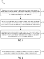
- FIG. 2 shows a flowchart of an example method for use with the method 100, according to an example implementation.
- functions include applying vibration to the metallic material of the first layer. Vibrating a deposited layer of molten material causes a relative shear motion of the molten material against nucleating solids on an underlying substrate that the layer is positioned on. As a result, dendrites growing in molten material can undergo defragmentation where portions of dendrites fracture and detach. These detached portions can reposition in the molten material and form nucleation sites that subsequently grow new crystals at spatially-random orientations during solidification. The growth of these crystals causes the refined microstructure of the solidified layer of material to have a balanced arrangement of smaller grains that improve properties of the layer.
- FIG. 3 shows a flowchart of an example method for use with the method 100, according to an example implementation.
- functions include applying a cooling gas flow to the metallic material of the first layer.
- a cooling gas or other temperature reduction techniques can be used to cool a deposited layer of material.
- a cooling technique can be used to undercool a layer of molten material to cause the layer to undergo solidification.
- the cooling gas or another temperature reduction technique can be used to reduce an amount of time available for dendrites of the metallic material to grow.
- the application of cooling gas can occur after depositing the metallic material as a layer to limit a subset of dendrites from dominating growth due to epitaxial growth.
- cooling gas or another temperature reduction technique is applied before or after one or multiple vibration and/or electromagnetic field techniques are applied to a given layer of metallic material.
- FIG. 4 shows a flowchart of an example method for use with the method 100, according to an example implementation.
- functions include applying an electromagnetic field to a metallic material of the second layer. Similar to the generation of the first layer, electromagnetic fields can also be applied to the second layer to promote restructuring of the microstructure of the second layer of metallic material.
- the application of electromagnetic fields can differ across different layers during additive manufacturing. For instance, the duration, amount, quantity, and other factors of applying electromagnetic fields can differ for each layer.
- functions include generating a third layer of the integral object.
- additive manufacturing generates the integral object by consolidating multiple layers of material.
- additional layers are deposited on top of prior layers until the integral object is complete.
- the quantities, sizes, and forms of additional layers depend on the dimensions and design of the integral object. Particularly, some layers can have more or less material in different shapes depending on the design of the integral object.
- electromagnetic fields and/or vibration techniques are similarly applied to these layers.
- the techniques used can remain the same or differ between layers. For instance, an example can involve alternating between applying electromagnetic fields to some layers and applying vibration to other layers.
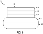
- FIG. 5 is an illustration of an apparatus 116 generated using microstructure refinement techniques during additive manufacturing.
- the apparatus 116 involves an integral object 118 made up of one or multiple interconnected components generated and blended together during additive manufacturing. As shown, the integral object 118 is made up of a first layer 120, a second layer 122, a third layer 124, a fourth layer 126, and a fifth layer 128.
- Other additively manufactured integral objects can have more or fewer layers shaped in other configurations.
- the apparatus 116 represents an additively manufactured vase configured to hold and display flowers.
- the method 100 shown in Figures 1-4 or another additive manufacturing technique can create apparatus 116.
- Each deposited layer i.e., the layers 120-128 is shown with noticeable borders for illustration purposes to depict the layout of the different layers 120-128.
- the layers 120-128 can consist of various metallic materials, such as aluminum, titanium, alloys, etc.
- the height and width of the layers 120-128 are exaggerated in Figure 5 for illustration purposes, but can be smaller within implementations.
- one or multiple electromagnetic fields can be applied to the molten material of the first layer 120.
- vibration techniques can also be used to help restructure the microstructure of the metallic material making up the first layer 120. As discussed above, these techniques can cause restructuring by creating new nucleation sites that grow crystals at spatially-random orientations.
- the second layer 122 is deposited on the first layer 120 to form a portion of the integral object 118.
- the second layer 122 is deposited immediately after the first layer 120 receives electromagnetic fields and/or vibration.
- the first layer 120 is allowed to cool off and release some energy before the second layer 122 is deposited.
- the second layer 122 can be deposited directly onto the first layer 120, for example.
- the above process involving electromagnetic fields and/or vibration techniques is repeated to strengthen layers as the additional layers (e.g., the third layer 124, the fourth layer 126, and the fifth layer 128) are deposited. This repetition across multiple layers improves the overall strength of the apparatus 116 and can ensure that adding water and flowers does not weaken the integral object 118.
- FIG. 6 is an illustration of dendritic growth of a metallic material.
- Frame 130 shows dendrites 132, 134, 136 growing to illustrate dendritic growth of a metallic material.
- a dendrite is a crystal mass with a branching, treelike structure.
- Frame 130 shows dendrite 132 and dendrite 136 having similar sizes with dendrite 134 having a slightly larger size comparatively.
- the larger size of dendrite 134 can indicate that dendrite 134 is dominating growth impacting the growth of dendrites 132, 136.
- dendrite 134 can grow into an elongated grain.
- frame 130 can represent a situation involving multiple dendrites 132-136 dominating growth in a manner that likely causes a layer of metallic material to have more anisotropic properties due to elongated grains.
- Figure 7 is an illustration of modified dendritic growth of the metallic material shown in Figure 6 .
- frame 138 shows dendrites 132, 134, 136 in partially fractured and missing portions after an application one or more microstructure restructuring techniques, such as electromagnetic fields or vibration techniques described above.
- portions of the dendrites formed new nucleation sites 140, 142, and 144.
- These nucleation sites 140, 142, 144 can grow crystals that result in additional grains balancing the overall microstructure of the metallic material.
- FIG 8 is an illustration of subsequent dendritic growth of the metallic material shown in Figures 6 and 7 .
- Frame 146 represents a subsequent time after frame 138 when nucleation sites 140, 142, and 144 grow and produce dendrites that have similar sizes to original dendrites 132, 134, and 136.
- the dendrites 132, 134, 136 and nucleation sites 140, 142, 144 can cause a restructuring of the microstructure of the metallic material.
- Each dendrite can produce one or multiple crystals are spatially-random orientations that grown until reaching a threshold limit of growth imposed by other dendrites.
- the resulting refined microstructure includes equiaxed grains that have spatially-random orientations.
- Figure 10 is an illustration of refined grains that make up part of the microstructure of the deposited layer shown in Figure 9 .
- the portion 156 represents the deposited layer described in Figure 9 after the layer undergoes one or multiple techniques involving electromagnetic fields and vibration.
- the portion 156 includes smaller grains (e.g., grains 158, 16) having spatially-random orientations. These rounded, smaller grains replace the elongated grains 150-154 shown in Figure 9 increasing the strength of the layer.
- the strengthen layer allows for an additively manufactured structure with more isotropic properties that can improve the use and durability of the structure.
- the method 162 involves applying an electromagnetic field to the metallic material of the first layer.
- the application of one or more electromagnetic fields perturbs the first layer of metallic material causing one or multiple nucleation sites to form in the molten material.
- the nucleation sites can form at the solid-liquid interface of the molten material.
- the method 162 involves applying vibration to the metallic material of the first layer. Similar to electromagnetic fields, vibration can perturb molten material during additive manufacturing. Particularly, vibration can cause one or multiple dendrites growing in the metallic material in the molten state to fracture and detach. The portions that detach from the original dendrites can form nucleation sites within the molten material. In some instances, vibration increases in a number of nucleation sites at the solid-liquid interface of the metallic material.
- applying vibration to the metallic material of the first layer is performed in parallel with applying the electromagnetic field to the metallic material of the first layer. In other examples, vibration is applied to the metallic material before and/or after electromagnetic fields is applied to the layer.
- the method 162 involves generating a second layer of the integral object coupled to the first layer of the integral object.
- generating the second layer increases the number of nucleation sites at the solid-liquid interface of the metallic material in the molten state.
- each nucleation site can grow a crystal at a spatially-random orientation.
- the resulting refined microstructure of the metallic material is made up of new grains that have equiaxed grain structures that can cause the first layer to have more isotropic properties.
- the new grains can have similar sizes and random orientations that modify the properties of the layer of material.
Landscapes
- Engineering & Computer Science (AREA)
- Manufacturing & Machinery (AREA)
- Chemical & Material Sciences (AREA)
- Materials Engineering (AREA)
- Physics & Mathematics (AREA)
- Optics & Photonics (AREA)
- Mechanical Engineering (AREA)
- Plasma & Fusion (AREA)
- Health & Medical Sciences (AREA)
- General Health & Medical Sciences (AREA)
- Toxicology (AREA)
- Robotics (AREA)
- Composite Materials (AREA)
- Powder Metallurgy (AREA)
- Welding Or Cutting Using Electron Beams (AREA)
- Laser Beam Processing (AREA)
- Photovoltaic Devices (AREA)
Abstract
Description
- The present disclosure relates generally to additive manufacturing processes, and more particularly, to techniques for refining the microstructure of metallic materials used for additive manufacturing.
- Unlike traditional manufacturing that relies on subtractive techniques (e.g., cutting, drilling) to remove material from bulk shapes to arrive at a final shape, additive manufacturing builds shapes through precisely adding and consolidating layers of material according to a three-dimensional (3D) digital model. Depending on the underlying material used, various consolidation techniques are available to additively manufacture a desired structure, such as powder bed fusion, direct energy deposition (welding, electron-beam and laser processing), photo-polymerization, material jetting, binder jetting, and extrusion.
- Additive manufacturing is often used to create functional prototypes or components out of polymeric materials. Plastics, rubbers, and other polymeric materials are typically used since consolidation techniques for forming and blending layers of these materials together are economical and readily available. Conversely, metallurgical challenges associated with consolidating layers of metallic materials (e.g., metals, alloys, compounds) often reduce or even prevent their use for additive manufacturing. As a result, additive manufacturing typically only uses metallic materials to produce highly specialized components for medical, aviation, or other unique purposes.
- One reason that consolidation techniques are difficult for a metallic material is the underlying microstructure of the material. In particular, metals and alloys consist of a large number of irregularly shaped grains. Although indiscernible to the naked eye, the sizes and arrangement of the grains impact the material's properties, including its strength, ductility, strain rate, fatigue durability, and resistance to creep deformation, among other properties.
- When the layer of metallic material completely solidifies during additive manufacturing, the microstructure of the resulting material has more anisotropic properties that impact the durability, strength and other properties of the layer. Since additive manufacturing involves generating a structure through a layer by layer process, the anisotropic properties are often compounded due inconsistent dendritic growth that varies layer to layer.
- One technique currently used to reduce anisotropic properties in deposited layers involves applying a rolling wheel upon each layer prior to adding the subsequent layer. Although the rolling wheel technique can promote grain restructuring within deposited layers, the size and space required to use the rolling wheel limits its overall use to additively manufacturing processes depositing material with thicker features and simple geometrical shapes. Therefore, there is a need for technology that can refine the microstructure of a deposited layer of metallic material during additive manufacturing that can accommodate structures with various types of designs.
- In one example, a method is described. The method includes generating a first layer of an integral object using a metallic material. The integral object includes one or more interconnected components, and the first layer is generated by heating the metallic material to a molten state such that the metallic material includes a solid-liquid interface. The method further includes applying an electromagnetic field to the metallic material of the first layer. Particularly, the electromagnetic field perturbs the first layer of metallic material causing one or more nucleation sites to form at the solid-liquid interface of the metallic material in the molten state. The method also includes generating a second layer coupled to the first layer of the integral object. Generating the second layer increases a number of nucleation sites at the solid-liquid interface of the metallic material in the molten state. In some instances, each nucleation site grows a crystal at a spatially-random orientation.
- In another example, an apparatus is described. The apparatus comprises an integral object having one or more interconnected components. The integral object includes a first layer generated using a metallic material. The first layer is generated by heating the metallic material to a molten state such that the metallic material includes a solid-liquid interface. An electromagnetic field is applied to perturb the first layer of metallic material causing one or more nucleation sites to form at the solid-liquid interface of the metallic material in the molten state. The integral object also includes a second layer coupled to the first layer of the integral object. Generating the second layer increase a number of the nucleation sites at the solid-liquid interface of the metallic material in the molten state. In some instances, each nucleation site grows a crystal at a spatially-random orientation.
- In another example, a method is described. The method includes generating a first layer of an integral object using a metallic material. The integral object includes one or more interconnected components, and the first layer is generated by heating the metallic material to a molten state such that the metallic material includes a solid-liquid interface. The method further includes applying an electromagnetic field to the metallic material of the first layer. The electromagnetic field perturbs the first layer of metallic material causing one or more nucleation sites to form at the solid-liquid interface of the metallic material in the molten state. The method also includes applying vibration to the metallic material of the first layer. The vibration causes one or more dendrites growing in the metallic material in the molten state to fracture and detach resulting in an increase in a number of nucleation sites at the solid-liquid interface of the metallic material. The method also includes generating a second layer coupled to the first layer of the integral object. Particularly, generating the second layer increases the number of nucleation sites at the solid-liquid interface of the metallic material in the molten state. In some instances, each nucleation site grows a crystal at a spatially-random orientation.
- The features, functions, and advantages that have been discussed can be achieved independently in various examples or can be combined in yet other examples further details of which can be seen with reference to the following description and drawings.
- The novel features believed characteristic of the illustrative examples are set forth in the appended claims. The illustrative examples, however, as well as a preferred mode of use, further objectives and descriptions thereof, will best be understood by reference to the following detailed description of an illustrative example of the present disclosure when read in conjunction with the accompanying drawings, wherein:
-
Figure 1 shows a flowchart of an example method for refining the microstructure of a material used for additive manufacturing, according to an example implementation. -
Figure 2 shows a flowchart of an example method for use with the method shown inFigure 1 , according to an example implementation. -
Figure 3 shows a flowchart of another example method for use with the method shown inFigure 1 , according to an example implementation. -
Figure 4 shows a flowchart of a further example method for use with the method shown inFigure 1 , according to an example implementation. -
Figure 5 is an illustration of an apparatus generated using microstructure refinement techniques during additive manufacturing, according to an example implementation. -
Figure 6 is an illustration of dendritic growth of a metallic material, according to an example implementation. -
Figure 7 is an illustration of modified dendritic growth of the metallic material shown inFigure 6 , according to an example implementation. -
Figure 8 is an illustration of subsequent dendritic growth of the metallic material shown inFigures 6 and 7 , according to an example implementation. -
Figure 9 is an illustration of elongated grains that make up part of the microstructure of a deposited layer. -
Figure 10 is an illustration of refined grains that make up part of the microstructure of the deposited layer shown inFigure 9 . -
Figure 11 shows a flowchart of an example method for refining the microstructure of a metallic metal used for additive manufacturing, according to an example implementation. - Disclosed examples will now be described more fully hereinafter with reference to the accompanying drawings, in which some, but not all of the disclosed examples are shown. Indeed, several different examples can be described and should not be construed as limited to the examples set forth herein. Rather, these examples are described so that this disclosure will be thorough and complete and will fully convey the scope of the disclosure to those skilled in the art.
- The examples relate to techniques for refining the microstructure of metallic material layers during additive manufacturing. Particularly, examples techniques perturb or otherwise modify a layer of metallic material when the material is in a molten state (i.e., melt pool). By using one or multiple techniques presented herein during additive manufacturing to refine the microstructure of a metallic material layer, the properties of the layer can be enhanced resulting in improvements to strength, ductility, fatigue, durability, strain rate, and resistance to creep deformation, among other properties.
- The sizes and arrangement of grains within a material's microstructure typically depend on the formation conditions that influence dendritic growth of the metallic material. When a metallic material is manufactured by an additive process, it is melted and deposited as desired to form a layer of structure. The heat causes the metallic material to change into a locally molten state that enables the resulting product to be shaped into a particular form. Once enough heat leaves the molten material to drop the material below its melting point temperature, the material transitions back from the liquid, molten state to a solid state in a process called solidification.
- During solidification, nucleation and growth transformation occurs within the metallic material. Nucleation involves clusters of atoms from the molten material bonding together and forming tiny seed crystals. The tiny seed crystals originate at locations in the material that are referred to herein as nucleation sites and continue to grow in the form of dendrites, which are tree-like structures made up of crystals. The formation of dendrites occurs because crystals grow into a thermal gradient termed a mushy zone consisting of both liquid and solid phases. In some instances, heterogeneous nucleation occurs during solidification with nucleation sites forming on impurity surfaces or particles, such as relative to the substrate or prior layer, insoluble detached impurities, or other structural materials that lower the critical free energy required for atoms to form stable nuclei crystals. The crystals of dendrites increase in size by adding more atoms until growth is limited by other dendrites growing in the molten material or the dendrites encounter the liquid at a temperature above the local melting point temperature.
- Solidification during additive manufacturing often involves uneven dendritic growth that causes the layer of metallic material to have an unbalanced grain structure. Particularly, energetically favorable crystallographic directions, the underlying substrate or prior layer, impurities, directional use of heat source (e.g., laser) as well as other factors can cause some dendrites to exhibit more rapid growth than others during solidification. The dendrites that dominate growth often result in elongated grains that have columnar orientations. These elongated, columnar grains are long, thin, coarse grains that can arise, such as in situations when the metallic material solidifies rather slowly in the presence of a steep temperature gradient. The predominant dendrites also prevent adjacent dendrites growing at other orientations from experiencing the same amount of growth.
- As discussed above, a deposited layer of metallic material transitions back from a molten state to a solid state via solidification. Unbalanced nucleation and growth during solidification might cause the metallic material layer to have anisotropic properties. Particularly, epitaxial growth and other factors can cause the grain microstructure of the metallic material to have elongated, columnar grains that negatively impact the strength and other properties of the layer. Further, since additive manufacturing involves generating layers upon layers to create a desired structure, the effects of the impact are compounded and negatively influence the performance and effectiveness of the structure.
- In order to improve the durability, strength, and other properties of layers of metallic material, example techniques presented herein refine the microstructures of the layers during additive manufacturing. Particularly, some examples involve applying one or multiple electromagnetic fields upon portions of a deposited metallic material layer when the material is in the molten state. The application of electromagnetic fields stirs and perturbs the molten material causing new nucleation sites to form at various locations within the molten material (e.g., at the solid-liquid interface). As a result, these nucleation sites can grow new crystals during when the molten material undergoes solidification. The new crystals are arranged at spatially-random orientations within the metallic material causing the refined microstructure of the layer to smaller, equiaxed grains that are randomly oriented. This refined microstructure provides improvements to strength, ductility, fatigue durability, strain rate, and resistance to creep deformation among other properties.
- Additional examples involve applying vibration to deposited layers of metallic material during additive manufacturing to refine the microstructure of the layers. The vibration can perturb or otherwise modify a layer of metallic material when the material is in a molten state. For instance, after a layer of metallic material is initially heated and shaped, vibration can be applied to stir the portions of the material that are in a melt pool state. The vibration can cause a relative shear motion of molten material relative to nucleating solids of an underlying substrate that the layer is positioned upon. As a result, dendrites growing in the molten material undergo defragmentation. During defragmentation, portions of dendrites fracture and detach. These portions that detach from the original dendrites can form new nucleation sites in the molten material. For example, some of the detached dendrite portions can attach and nucleate at the solid-liquid interface of the molten material. The nucleation sites subsequently grow crystals at spatially-random orientations, resulting in the vibrated layer having a more balanced grain structure that provides improvements to strength, ductility, fatigue durability, strain rate, and resistance to creep deformation among other properties.
- In some examples, a combination of vibration and electromagnetic field techniques are used to restructure the microstructure of deposited layers of metallic materials. Both techniques can be applied to a layer simultaneously or in a given order. For instance, an example can involve a molten layer of material receiving vibration, then electromagnetic fields, and more vibration during the deposition process. The techniques can be utilized for various durations and intensities as well. Further, some examples involve switching between vibration and electromagnetic field techniques for different layers during additive manufacturing.
- The above techniques as well as similar processes can reduce or potentially eliminate the need for other stress relieving processes during additive manufacturing. In turn, overall cost and flow time is often reduced by eliminating process steps. In addition, unlike the rolling wheel technique, electromagnetic fields and vibration techniques do not place limits on the geometrical designs of a structure for additive manufacturing. For instance, the techniques can be used quickly on desired structures that are small in size (e.g., centimeters in measurements) and can be used on all layers (or a subset of layers) of the desired structure during additive manufacturing. Further, in some examples, the electromagnetic field and vibration techniques can both use setups that require fewer components than the rolling wheel technique. The strain-free grains that originate from newly formed nucleation sites typically have similar sizes and morphologies unlike the elongated grains that they are replacing. The replacement grains also tend to have spatially-random orientations causing the layer to have more isotropic properties rather than anisotropic. Isotropic properties indicates that the properties of the layer are consistent regardless the direction of measurement.
- In order to improve the properties of an additively manufactured structure, in some examples, the above techniques can be applied to all layers (or a subset of layers) during additive manufacturing. The outcome produces a strengthened structure that is less susceptible to tensile stress. Tensile stress represents the resistance of a structure to a force attempting to pull apart or stretch the structure and indicates the overall strength of the materials that make up the structure. As such, refining microstructure through vibration and/or electromagnetic field techniques can produce layers and overall additively manufactured structures made out of metallic materials less susceptible to tensile stress and other material defects.
- Referring now to the Figures,
Figure 1 shows a flowchart of an example method for refining the microstructure of a material used for additive manufacturing.Method 100 shown inFigure 1 presents an example of a method that could be used to refine the microstructure of one or more materials used during additive manufacturing. -
Method 100 can include one or more operations, functions, or actions as illustrated by one or more ofblocks - At
block 102, themethod 100 involves generating a first layer of an integral object using a metallic material. An integral object is a structure with one or multiple components formed together as a single-piece. For instance, an integral object can be an additively manufactured structure that serves as a component of a larger structure. In other examples, an integral object can be standalone object. Other examples of integral objects are possible. Further, unlike traditional manufacturing, additively manufactured objects do not require fasteners (e.g., screws, nails) to have multiple elements connected or joined together. As a result, the layer and consolidation process of additive manufacturing enables production of a wide array of integral objects with various shapes and designs. - As indicated above, additive manufacturing involves heating and depositing layers of one or multiple metallic materials together to form a desired integral object according to a 3D data model. Example metallic materials that can be used include, but are not limited to, titanium, gold, silver, steel, aluminum, and alloys. In some instances, compounds of materials can also be used. For instance, a compound can include a metal and a non-metal combined together. The materials selected for an additively manufactured object typically depend on the cost of materials and the dimensions and desired use of the object.
- During the deposition of a layer, a metallic material is heated and shaped. For example, some materials, such as titanium alloys have melting ranges between 1600-1660°C. The material (e.g., molten alloy) is locally heated well above this temperature by the incident energy, typically a laser or electron beam, and momentarily to 3,000-4,000 °C, before it cools and solidifies. For instance, in powder feed additive manufacturing processes, powder layers are consolidated layer by layer using a focused heat source (e.g., laser). This enables a component to be generated directly from a computer aided design (CAD) data. In other examples, other types of additive manufacturing techniques are used. For instance, an example can involve using a wire feed additive manufacturing process.
- In some instances, the first layer is generated by heating the metallic material to a molten state such that the metallic material includes a solid-liquid interface. To form portions of the structure, the material or materials selected for the first layer (and additional layers) are configurable to couple to subsequent layers with the layers blended together create a seamless end structure.
- After the metallic material is heated into the molten state, the temperature of the material decreases. When the metallic material decreases in temperature below its melting temperature, solidification occurs. The molten material loses heat as the time since the material was initially heated passes. During solidification, atoms from the molten material bond together (e.g., metallic bonds) and start to form tiny seed crystals microscopic in size (e.g., less than 1 millimeter). After a tiny seed crystal starts to grow, the crystal can be described as a nucleus growing from a nucleation site. As such, solidification involves multiple crystals growing in the form of dendrites in the molten material. Various factors, such as the underlying substrate or prior layer, impurities, directional nature of the applied heat source, etc., can result in unbalanced growth of dendrites of crystals with some dendrites dominating growth causing the layer to have more anisotropic properties. The anisotropic properties cause the metallic material to differ depending on direction of measurement with some portions of the metallic material having more strength than others portions.
- At
block 104, themethod 100 involves applying an electromagnetic field to the metallic material of the first layer. After depositing the first layer of metallic material, the layer can have anisotropic properties as a result of epitaxial growth of dendrites producing elongated grains. In order to reduce anisotropic properties, one or multiple electromagnetic fields are applied to portions of the metallic material in the molten state. The electromagnetic fields perturb the metallic material causing new nucleation sites to form in the molten material. For instance, numerous nucleation sites can originate at the solid-liquid interface of the molten material. - The application of electromagnetic fields can involve using various types of electrical sources. For instance, an example source can utilize power from a wall-outlet or battery to apply electromagnetic fields upon the first layer as well as other deposited layers during additive manufacturing. In addition, the method of application and duration can vary within examples. Electromagnetic fields are applied upon a layer of molten material for a threshold duration of time that depends on the type and quantity of material making up the layer. For instance, some examples can involve applying electromagnetic fields for a few seconds (e.g., 5-10 seconds) or longer (e.g., 30 seconds). In further examples, electromagnetic fields are applied for longer durations (e.g., 2 minutes, 5 minutes). The threshold duration can depend on various factors, such as the thickness and other dimensions of the layer of metallic material as well as the type of metallic material.
- At
block 106, themethod 100 involves generating a second layer coupled to the first layer of the integral object. In order to produce the integral object, additional layers are deposited until the structure of the integral object is completely formed. The additional layers can be formed from the same material or different material from prior layers. In addition, the second layer and other subsequent layers can have the same dimensions (e.g., thickness) or different dimensions depending on the formation of the desired structure. - Generating a second layer coupled to the first layer of the integral object can increase a number of nucleation sites in the molten material of the first layer. The heat and presence of the second layer can impact the nucleation and growth of the first layer. For instance, the presence of the second layer on top of the nearly solidified first layer can cause heterogeneous nucleation to occur relative to the coupling point between the layers.
- As discussed above, these nucleation sites can grow crystals at spatially-random orientations. When dendrites of crystals can no longer grow due to limits placed by other dendrites growing within the layer, the arrangement of these crystals form the refined grain microstructure of the metallic material. Particularly, this refined microstructure is made up of smaller, equiaxed grains that have random orientations unlike columnar, elongated grains. As result, the layer has increased isotropic properties improving its overall strength, ductility, and other properties.
-
Figure 2 shows a flowchart of an example method for use with themethod 100, according to an example implementation. Atblock 108, functions include applying vibration to the metallic material of the first layer. Vibrating a deposited layer of molten material causes a relative shear motion of the molten material against nucleating solids on an underlying substrate that the layer is positioned on. As a result, dendrites growing in molten material can undergo defragmentation where portions of dendrites fracture and detach. These detached portions can reposition in the molten material and form nucleation sites that subsequently grow new crystals at spatially-random orientations during solidification. The growth of these crystals causes the refined microstructure of the solidified layer of material to have a balanced arrangement of smaller grains that improve properties of the layer. - The amount of vibration (e.g., amplitude, duration) can vary within examples. For instance, vibration techniques can involve both sonic and ultrasonic application approaches applied in either a periodic or continuous manner during deposition of a given layer. In some examples, sonic vibration ranges can range between 100 to 400 Hertz and ultrasonic vibration ranges can range between 20 to 45 Megahertz. The sonic and ultrasonic vibration ranges can depend on the source providing the vibration. As such, the sonic vibration and/or ultrasonic vibration can direct energy towards a deposited layer of metallic material. For instance, the energy can perturb molten metallic material after deposition during additive manufacturing. Other high frequency mechanical impact processes can be used within examples.
- In some examples, applying vibration to the metallic material of the first layer is performed in parallel with applying the electromagnetic field to the metallic material of the first layer. As an example, during an additive manufacturing process, each deposited layer of molten material can receive vibration while also receiving electromagnetic fields to improve properties. In other examples, vibration is applied to the substrate prior to applying the electromagnetic field to the metallic material of the first layer. Further, in some instances, vibration is applied to a layer of molten material after the layer is modified by one or multiple electromagnetic fields.
-
Figure 3 shows a flowchart of an example method for use with themethod 100, according to an example implementation. Atblock 110, functions include applying a cooling gas flow to the metallic material of the first layer. During additive manufacturing, a cooling gas or other temperature reduction techniques can be used to cool a deposited layer of material. For instance, a cooling technique can be used to undercool a layer of molten material to cause the layer to undergo solidification. The cooling gas or another temperature reduction technique can be used to reduce an amount of time available for dendrites of the metallic material to grow. For instance, the application of cooling gas can occur after depositing the metallic material as a layer to limit a subset of dendrites from dominating growth due to epitaxial growth. In other examples, cooling gas or another temperature reduction technique is applied before or after one or multiple vibration and/or electromagnetic field techniques are applied to a given layer of metallic material. -
Figure 4 shows a flowchart of an example method for use with themethod 100, according to an example implementation. Atblock 112, functions include applying an electromagnetic field to a metallic material of the second layer. Similar to the generation of the first layer, electromagnetic fields can also be applied to the second layer to promote restructuring of the microstructure of the second layer of metallic material. The application of electromagnetic fields can differ across different layers during additive manufacturing. For instance, the duration, amount, quantity, and other factors of applying electromagnetic fields can differ for each layer. - At
block 114, functions include generating a third layer of the integral object. As indicated above, additive manufacturing generates the integral object by consolidating multiple layers of material. As such, in order to form and complete the integral object, additional layers are deposited on top of prior layers until the integral object is complete. The quantities, sizes, and forms of additional layers depend on the dimensions and design of the integral object. Particularly, some layers can have more or less material in different shapes depending on the design of the integral object. - To ensure the additional layers maintain similar refined microstructures, electromagnetic fields and/or vibration techniques are similarly applied to these layers. The techniques used can remain the same or differ between layers. For instance, an example can involve alternating between applying electromagnetic fields to some layers and applying vibration to other layers.
-
Figure 5 is an illustration of anapparatus 116 generated using microstructure refinement techniques during additive manufacturing. Theapparatus 116 involves anintegral object 118 made up of one or multiple interconnected components generated and blended together during additive manufacturing. As shown, theintegral object 118 is made up of afirst layer 120, asecond layer 122, athird layer 124, afourth layer 126, and afifth layer 128. Other additively manufactured integral objects can have more or fewer layers shaped in other configurations. - The
apparatus 116 represents an additively manufactured vase configured to hold and display flowers. Themethod 100 shown inFigures 1-4 or another additive manufacturing technique can createapparatus 116. Each deposited layer (i.e., the layers 120-128) is shown with noticeable borders for illustration purposes to depict the layout of the different layers 120-128. The layers 120-128 can consist of various metallic materials, such as aluminum, titanium, alloys, etc. In addition, the height and width of the layers 120-128 are exaggerated inFigure 5 for illustration purposes, but can be smaller within implementations. - When additively manufacturing the
apparatus 116, each layer of theintegral object 118 can be strengthened using one or multiple techniques discussed above before depositing the next layer. For instance, generation of theapparatus 116 initially involves depositing and forming thefirst layer 120 on a substrate. Epitaxial growth relative to the substrate can cause unbalanced dendrite growth that impacts the properties of thefirst layer 120. The substrate can serve as a platform for holding layers during additive manufacturing. - After depositing the
first layer 120, one or multiple electromagnetic fields can be applied to the molten material of thefirst layer 120. Similarly, vibration techniques can also be used to help restructure the microstructure of the metallic material making up thefirst layer 120. As discussed above, these techniques can cause restructuring by creating new nucleation sites that grow crystals at spatially-random orientations. - After the
first layer 120 is prepared during additive manufacturing, thesecond layer 122 is deposited on thefirst layer 120 to form a portion of theintegral object 118. In some instances, thesecond layer 122 is deposited immediately after thefirst layer 120 receives electromagnetic fields and/or vibration. In other cases, thefirst layer 120 is allowed to cool off and release some energy before thesecond layer 122 is deposited. Thesecond layer 122 can be deposited directly onto thefirst layer 120, for example. - The above process involving electromagnetic fields and/or vibration techniques is repeated to strengthen layers as the additional layers (e.g., the
third layer 124, thefourth layer 126, and the fifth layer 128) are deposited. This repetition across multiple layers improves the overall strength of theapparatus 116 and can ensure that adding water and flowers does not weaken theintegral object 118. -
Figure 6 is an illustration of dendritic growth of a metallic material.Frame 130 showsdendrites Frame 130 shows dendrite 132 anddendrite 136 having similar sizes withdendrite 134 having a slightly larger size comparatively. In some instances, the larger size ofdendrite 134 can indicate thatdendrite 134 is dominating growth impacting the growth ofdendrites 132, 136. As a result,dendrite 134 can grow into an elongated grain. In other examples,frame 130 can represent a situation involving multiple dendrites 132-136 dominating growth in a manner that likely causes a layer of metallic material to have more anisotropic properties due to elongated grains. -
Figure 7 is an illustration of modified dendritic growth of the metallic material shown inFigure 6 . Particularly,frame 138 showsdendrites -
Figure 8 is an illustration of subsequent dendritic growth of the metallic material shown inFigures 6 and 7 .Frame 146 represents a subsequent time afterframe 138 when nucleation sites 140, 142, and 144 grow and produce dendrites that have similar sizes tooriginal dendrites dendrites -
Figure 9 is an illustration of elongated grains that make up part of the microstructure of a deposited layer. Theportion 148 of the deposited layer shown inFigure 9 includes anelongated grain 150, anelongated grain 152, and anelongated grain 154 arranged in columnar orientations. After a layer is deposited during additive manufacturing, epitaxial growth causes some dendrites to dominate growth resulting in elongated grains 150-154. As shown inFigure 9 , these elongated grains 150-154 often form together in a particular orientation that causes the deposited layer to have more anisotropic properties likely negatively impacting strength, durability, and other properties. The growth of some dendrites producing these elongated grains 150-154 also prevents other dendrites at different orientations in the layer from experiencing similar growth. For these reasons, electromagnetic field and/or vibration techniques can be used during additive manufacturing to deform and allow restructuring of the grain microstructure to reduce the anisotropic properties. -
Figure 10 is an illustration of refined grains that make up part of the microstructure of the deposited layer shown inFigure 9 . In particular, theportion 156 represents the deposited layer described inFigure 9 after the layer undergoes one or multiple techniques involving electromagnetic fields and vibration. As shown, theportion 156 includes smaller grains (e.g.,grains 158, 16) having spatially-random orientations. These rounded, smaller grains replace the elongated grains 150-154 shown inFigure 9 increasing the strength of the layer. As a result, the strengthen layer allows for an additively manufactured structure with more isotropic properties that can improve the use and durability of the structure. -
Figure 11 shows a flowchart of an example method for refining the microstructure of a metal used for additive manufacturing.Method 162 shown inFigure 11 presents another example of a method that could be used to refine the microstructure of a metal or another material used during additive manufacturing. -
Method 162 can include one or more operations, functions, or actions as illustrated by one or more ofblocks - At
block 164, themethod 162 involves generating a first layer of an integral object using a metallic material. Particularly, the first layer is deposited using a metal (e.g., titanium, aluminum) or metallic alloy that grows such that a set of dendrites dominate the overall growth producing elongated grains. For instance, the elongated grains can align in columnar orientations. A few dendrites dominating growth can prevent other dendrites in opposing orientations from growing as much. As a result, the deposited layer of metal can have anisotropic properties. - At
block 166, themethod 162 involves applying an electromagnetic field to the metallic material of the first layer. The application of one or more electromagnetic fields perturbs the first layer of metallic material causing one or multiple nucleation sites to form in the molten material. For instance, the nucleation sites can form at the solid-liquid interface of the molten material. - At
block 168, themethod 162 involves applying vibration to the metallic material of the first layer. Similar to electromagnetic fields, vibration can perturb molten material during additive manufacturing. Particularly, vibration can cause one or multiple dendrites growing in the metallic material in the molten state to fracture and detach. The portions that detach from the original dendrites can form nucleation sites within the molten material. In some instances, vibration increases in a number of nucleation sites at the solid-liquid interface of the metallic material. - In some examples, applying vibration to the metallic material of the first layer is performed in parallel with applying the electromagnetic field to the metallic material of the first layer. In other examples, vibration is applied to the metallic material before and/or after electromagnetic fields is applied to the layer.
- At
block 170, themethod 162 involves generating a second layer of the integral object coupled to the first layer of the integral object. In particular, generating the second layer increases the number of nucleation sites at the solid-liquid interface of the metallic material in the molten state. As such, each nucleation site can grow a crystal at a spatially-random orientation. With multiple nucleation sites growing crystals that form new grains. The resulting refined microstructure of the metallic material is made up of new grains that have equiaxed grain structures that can cause the first layer to have more isotropic properties. The new grains can have similar sizes and random orientations that modify the properties of the layer of material. - Further, the disclosure comprises examples according to the following clauses:
-
Clause 1. A method comprising: generating a first layer of an integral object using a metallic material, wherein the integral object includes one or more interconnected components, and wherein the first layer is generated by heating the metallic material to a molten state such that the metallic material includes a solid-liquid interface; applying an electromagnetic field to the metallic material of the first layer, wherein the electromagnetic field perturbs the first layer causing one or more nucleation sites to form at the solid-liquid interface of the metallic material in the molten state; and generating a second layer coupled to the first layer of the integral object, wherein generating the second layer increases a number of nucleation sites at the solid-liquid interface of the metallic material in the molten state, and wherein each nucleation site grows a crystal at a spatially-random orientation. - Clause 2. The method of
Clause 1, further comprising: applying vibration to the metallic material of the first layer, wherein the vibration causes a relative shear motion of the metallic material in the molten state. - Clause 3. The method of Clause 2, wherein applying vibration to the metallic material of the first layer further causes one or more dendrites growing in the metallic material in the molten state to fracture and detach resulting in an increase in the number of nucleation sites at the solid-liquid interface of the metallic material.
-
Clause 4. The method of Clause 2 or 3, wherein applying vibration to the metallic material of the first layer is performed in parallel with applying the electromagnetic field to the metallic material of the first layer. - Clause 5. The method of Clause 2 or 3, wherein applying vibration to the metallic material of the first layer is performed prior to applying the electromagnetic field to the metallic material of the first layer.
- Clause 6. The method of Clause 2 or 3, wherein applying vibration to the metallic material of the first layer is performed after applying the electromagnetic field to the metallic material of the first layer.
- Clause 7. The method of any one of Clauses 1-6, wherein the metallic material is a metal, and wherein generating the first layer of the integral object using the metallic material comprises:
generating the first layer using wire feed additive manufacturing. - Clause 8. The method of any one of Clauses 1-7, wherein the metallic material is an alloy, and wherein generating the first layer of the integral object using the metallic material comprises: generating the first layer using powder feed additive manufacturing.
- Clause 9. The method of any one of Clauses 1-8, wherein generating the first layer of the integral object using the metallic material comprises: depositing the first layer on a substrate such that a plurality of elongated grains originate from epitaxial growth of a set of dendrites in the metallic material in the molten state, wherein the plurality of elongated grains have columnar orientations that cause the first layer of the integral object to have anisotropic properties.
- Clause 10. The method of Clause 9, wherein applying the electromagnetic field to the metallic material of the first layer comprises: applying the electromagnetic field to stir the metallic material in the molten state, wherein stirring the metallic material in the molten state decreases the plurality of elongated grains, and wherein decreasing the plurality of elongated grains increases the number of nucleation sites at the solid-liquid interface of the metallic material in the molten state.
- Clause 11. The method of Clause 9 or 10, wherein generating the second layer coupled to the first layer of the integral object causes nucleation sites at the solid-liquid interface of the metallic material in the molten state to grow crystals at spatially-random orientations, wherein the crystals form new grains that are smaller than the elongated grains, and wherein the new grains have equiaxed grain structures that cause the first layer of the metallic material to have more isotropic properties.
- Clause 12. The method of any one of Clauses 1-11, wherein applying the electromagnetic field to the metallic material of the first layer reduces a temperature of the metallic material in the molten state below a melting point temperature for the metallic material.
- Clause 13. The method of Clause 12, wherein reducing the temperature of the metallic material in the molten state below the melting point temperature for the metallic material causes the metallic material to perform solidification.
- Clause 14. The method of any one of Clauses 1-12, further comprising: applying a cooling gas flow to the metallic material of the first layer, wherein the cooling gas reduces an amount of time available for dendrites of the metallic material to grow.
- Clause 15. The method of any one of Clauses 1-14, further comprising: applying an electromagnetic field to a metallic material of the second layer, wherein the metallic material of the second layer is in a molten state; and generating a third layer of the integral object, wherein the third layer is coupled to the second layer.
- Clause 16. An apparatus comprising: an integral object having one or more interconnected components, wherein the integral object comprises: a first layer generated using a metallic material, wherein the first layer is generated by heating the metallic material to a molten state such that the metallic material includes a solid-liquid interface, and wherein an electromagnetic field is applied to perturb the first layer causing one or more nucleation sites to form at the solid-liquid interface of the metallic material in the molten state; and a second layer coupled to the first layer of the integral object, wherein generating the second layer increases a number of the nucleation sites at the solid-liquid interface of the metallic material in the molten state, and wherein each nucleation site grows a crystal at a spatially-random orientation.
- Clause 17. The apparatus of Clause 16, wherein vibration is applied to the first layer to stir the metallic material in the molten state, and wherein the vibration causes one or more dendrites growing in the metallic material in the molten state to fracture and detach resulting in an increase in a number of nucleation sites at the solid-liquid interface of the metallic material.
- Clause 18. The apparatus of Clause 16 or 17, wherein the vibration is applied to the first layer in parallel with an application of the electromagnetic field to perturb the first layer.
- Clause 19. The apparatus of Clause 16 or 17, wherein the vibration is applied to the first layer after the electromagnetic field is applied to the first layer.
- Clause 20. A method comprising: generating a first layer of an integral object using a metallic material, wherein the integral object includes one or more interconnected components, and wherein the first layer is generated by heating the metallic material to a molten state such that the metallic material includes a solid-liquid interface; applying an electromagnetic field to the metallic material of the first layer, wherein the electromagnetic field perturbs the first layer causing one or more nucleation sites to form at the solid-liquid interface of the metallic material in the molten state; applying vibration to the metallic material of the first layer, where the vibration causes one or more dendrites growing in the metallic material in the molten state to fracture and detach resulting in an increase in a number of nucleation sites at the solid-liquid interface of the metallic material; and generating a second layer coupled to the first layer of the integral object, wherein generating the second layer increases the number of nucleation sites at the solid-liquid interface of the metallic material in the molten state, and wherein each nucleation site grows a crystal at a spatially-random orientation.
- By the term "substantially" or "about" used herein, it is meant that the recited characteristic, parameter, or value need not be achieved exactly, but that deviations or variations, including for example, measurement error, measurement accuracy limitations and other factors known to a person having ordinary skill in the art, can occur in amounts that do not preclude and/or occlude the effect the characteristic was intended to provide.
Claims (15)
- A method (100) comprising:generating (102) a first layer (120) of an integral object (118) using a metallic material, wherein the integral object (118) includes one or more interconnected components, and wherein the first layer (120) is generated by heating the metallic material to a molten state such that the metallic material includes a solid-liquid interface;applying (104) an electromagnetic field to the metallic material of the first layer (120), wherein the electromagnetic field perturbs the first layer (120) causing one or more nucleation sites to form at the solid-liquid interface of the metallic material in the molten state; andgenerating (106) a second layer (122) coupled to the first layer (120) of the integral object (118), wherein generating the second layer (122) increases a number of nucleation sites at the solid-liquid interface of the metallic material in the molten state, and wherein each nucleation site grows a crystal at a spatially-random orientation..
- The method of claim 1, further comprising:applying (108) vibration to the metallic material of the first layer (120), wherein the vibration causes a relative shear motion of the metallic material in the molten state, wherein applying (110) vibration to the metallic material of the first layer (120) preferably further causes one or more dendrites (132-136) growing in the metallic material in the molten state to fracture and detach resulting in an increase in the number of nucleation sites (140-144) at the solid-liquid interface of the metallic material.
- The method of claim 2, wherein applying vibration to the metallic material of the first layer (120) is performed in parallel with applying the electromagnetic field to the metallic material of the first layer (120).
- The method of claim 2 or 3, wherein applying vibration to the metallic material of the first layer (120) is performed prior to applying the electromagnetic field to the metallic material of the first layer (120).
- The method of claim 2 or 3, wherein applying vibration to the metallic material of the first layer (120) is performed after applying the electromagnetic field to the metallic material of the first layer (120).
- The method of any one of claims 1-5, wherein the metallic material is a metal, and wherein generating the first layer (120) of the integral object (118) using the metallic material comprises:generating the first layer (120) using wire feed additive manufacturing.
- The method of any one of claims 1-6, wherein the metallic material is an alloy, and wherein generating the first layer (120) of the integral object (118) using the metallic material comprises:generating the first layer (120) using powder feed additive manufacturing.
- The method of any one of claims 1-7, wherein generating the first layer (120) of the integral object (118) using the metallic material comprises:depositing the first layer (120) on a substrate such that a plurality of elongated grains (150-154) (150-154) originate from epitaxial growth of a set of dendrites (132-136) in the metallic material in the molten state, wherein the plurality of elongated grains (150-154) have columnar orientations that cause the first layer (120) of the integral object (118) to have anisotropic properties.
- The method of claim 8, wherein applying the electromagnetic field to the metallic material of the first layer (120) comprises:applying the electromagnetic field to stir the metallic material in the molten state, wherein stirring the metallic material in the molten state decreases the plurality of elongated grains (150-154), and wherein decreasing the plurality of elongated grains (150-154) increases the number of nucleation sites at the solid-liquid interface of the metallic material in the molten state, wherein generating the second layer (122) coupled to the first layer (120) of the integral object (118) preferably causes the nucleation sites at the solid-liquid interface of the metallic material in the molten state to grow crystals at spatially-random orientations, wherein the crystals form new grains (158) that are smaller than the elongated grains (150-154), and wherein the new grains (158) have equiaxed grain structures that cause the first layer (120) of the metallic material to have more isotropic properties.
- The method of any one of claims 1-9, wherein applying the electromagnetic field to the metallic material of the first layer (120) reduces a temperature of the metallic material in the molten state below a melting point temperature for the metallic material, wherein reducing the temperature of the metallic material in the molten state below the melting point temperature for the metallic material preferably causes the metallic material to perform solidification.
- The method of any one of claims 1-10, further comprising:applying a cooling spray to the metallic material of the first layer (120), wherein the cooling spray reduces an amount of time available for dendrites (132-136) of the metallic material to grow.
- The method of any one of claims 1-11, further comprising:applying an electromagnetic field to a metallic material of the second layer (122), wherein the metallic material of the second layer (122) is in a molten state; andgenerating a third layer (124) of the integral object (118), wherein the third layer (124) is coupled to the second layer (122).
- An apparatus (116) comprising:an integral object (118) having one or more interconnected components, wherein the integral object (118) comprises:a first layer (120) generated using a metallic material, wherein the first layer (120) is generated by heating the metallic material to a molten state such that the metallic material includes a solid-liquid interface, and wherein an electromagnetic field is applied to perturb the first layer (120) causing one or more nucleation sites to form at the solid-liquid interface of the metallic material in the molten state; anda second layer (122) coupled to the first layer (120) of the integral object (118), wherein generating the second layer (122) increases a number of the nucleation sites at the solid-liquid interface of the metallic material in the molten state, and wherein each nucleation site grows a crystal at a spatially-random orientation, wherein vibration is preferably applied to the first layer (120) to stir the metallic material in the molten state, and wherein the vibration causes one or more dendrites growing in the metallic material in the molten state to fracture and detach resulting in an increase in the number of nucleation sites at the solid-liquid interface of the metallic material.
- The apparatus of claim 13, wherein the vibration is applied to the first layer (120) in parallel with an application of the electromagnetic field to perturb the first layer (120) or wherein the vibration is applied to the first layer (120) after the electromagnetic field is applied to the first layer (120).
- A method (162) comprising:generating (164) a first layer (120) of an integral object (118) using a metallic material, wherein the integral object (118) includes one or more interconnected components, and wherein the first layer (120) is generated by heating the metallic material to a molten state such that the metallic material includes a solid-liquid interface;applying (166) an electromagnetic field to the metallic material of the first layer (120), wherein the electromagnetic field perturbs the first layer (120) causing one or more nucleation sites to form at the solid-liquid interface of the metallic material in the molten state;
applying (168) vibration to the metallic material of the first layer (120), where the vibration causes one or more dendrites growing in the metallic material in the molten state to fracture and detach resulting in an increase in a number of nucleation sites at the solid-liquid interface of the metallic material; andgenerating (170) a second layer (122) coupled to the first layer (120) of the integral object (118), wherein generating the second layer (122) increases the number of nucleation sites at the solid-liquid interface of the metallic material in the molten state, and wherein each nucleation site grows a crystal at a spatially-random orientation.
Applications Claiming Priority (1)
| Application Number | Priority Date | Filing Date | Title |
|---|---|---|---|
| US15/827,153 US11278963B2 (en) | 2017-11-30 | 2017-11-30 | Microstructure refinement methods by melt pool stirring for additive manufactured materials |
Publications (2)
| Publication Number | Publication Date |
|---|---|
| EP3492199A1 true EP3492199A1 (en) | 2019-06-05 |
| EP3492199B1 EP3492199B1 (en) | 2021-12-08 |
Family
ID=63787861
Family Applications (1)
| Application Number | Title | Priority Date | Filing Date |
|---|---|---|---|
| EP18198960.9A Active EP3492199B1 (en) | 2017-11-30 | 2018-10-05 | Microstructure refinement methods by melt pool stirring for additive manufactured materials |
Country Status (5)
| Country | Link |
|---|---|
| US (2) | US11278963B2 (en) |
| EP (1) | EP3492199B1 (en) |
| JP (1) | JP7398865B2 (en) |
| CN (1) | CN109986078B (en) |
| RU (1) | RU2018135646A (en) |
Families Citing this family (5)
| Publication number | Priority date | Publication date | Assignee | Title |
|---|---|---|---|---|
| CN112024877B (en) * | 2020-09-08 | 2022-05-03 | 常州英诺激光科技有限公司 | Method for improving surface quality of 3D printing micro-channel part |
| CN113857492B (en) * | 2021-10-09 | 2023-08-22 | 华中科技大学鄂州工业技术研究院 | Self-disturbance laser additive manufacturing method |
| CN115505922B (en) * | 2022-09-05 | 2024-09-03 | 北京航空航天大学 | Bottom epitaxial growth control method of metal additive manufacturing molten pool |
| CN115740494B (en) * | 2022-11-02 | 2024-10-11 | 成都先进金属材料产业技术研究院股份有限公司 | TiAl alloy blade and manufacturing method thereof |
| CN120395240B (en) * | 2025-07-02 | 2025-08-26 | 上海核工程研究设计院股份有限公司 | Composite welding method for end plugs of zirconium alloy fuel rods and zirconium alloy fuel rods |
Citations (6)
| Publication number | Priority date | Publication date | Assignee | Title |
|---|---|---|---|---|
| CN102240861B (en) * | 2011-04-26 | 2013-07-03 | 重庆大学 | Method and equipment for manufacturing gradient functional structure |
| US20150064047A1 (en) * | 2013-08-28 | 2015-03-05 | Elwha Llc | Systems and methods for additive manufacturing of three dimensional structures |
| EP2891533A1 (en) * | 2013-12-20 | 2015-07-08 | Industrial Technology Research Institute | Apparatus and method for adjusting and controlling the stacking-up layer manufacturing |
| CN105798299A (en) * | 2016-03-29 | 2016-07-27 | 上海大学 | Method for manufacturing metal part solidification structure by non-contact control added material and magnetron metal 3D printing device |
| WO2017097252A1 (en) * | 2015-12-11 | 2017-06-15 | The Hong Kong University Of Science And Technology | Method for additively manufacturing a component augmented by ultrasonic excitation and active temperature control |
| EP3038771B1 (en) * | 2013-08-29 | 2017-10-04 | European Space Agency | Manufacturing of a metal component or a metal matrix composite component involving contactless induction of high-frequency vibrations |
Family Cites Families (8)
| Publication number | Priority date | Publication date | Assignee | Title |
|---|---|---|---|---|
| US4743733A (en) | 1984-10-01 | 1988-05-10 | General Electric Company | Method and apparatus for repairing metal in an article |
| RU2359797C2 (en) | 2007-06-27 | 2009-06-27 | Федеральное Государственное Унитарное Предприятие "Центральный Научно-Исследовательский Институт Конструкционных Материалов "Прометей" (Фгуп "Цнии Км "Прометей") | Method of laser surfacing of copper-nickel alloys on details made of aluminium bronze |
| US8509575B2 (en) | 2009-06-02 | 2013-08-13 | Mitsubishi Electric Corporation | Semiconductor optical modulation device |
| DE102011078720A1 (en) * | 2011-07-06 | 2013-01-10 | Evonik Degussa Gmbh | Powder comprising polymer-coated core particles containing metals, metal oxides, metal or metalloid nitrides |
| CN103909267B (en) * | 2014-03-26 | 2015-11-04 | 浙江大学 | Based on semi-solid-state metal powder forming device and the manufacturing process of ultrasonic vibration |
| RU2618287C2 (en) | 2015-08-04 | 2017-05-03 | Федеральное государственное бюджетное образовательное учреждение высшего образования "Казанский национальный исследовательский технический университет им. А.Н. Туполева - КАИ" (КНИТУ-КАИ) | Method of laser treatment of article (versions) and device for its implementation (versions) |
| RU2617077C2 (en) | 2016-01-21 | 2017-04-19 | Общество с ограниченной ответственностью "КВАРЦ Групп" | Method of laser powder protective coating overlaying on the inlet edgs of steam turbines working blades |
| CN106180717B (en) * | 2016-09-15 | 2019-11-12 | 南京钛陶智能系统有限责任公司 | A kind of liquid material generating device and its control method for 3 D-printing |
-
2017
- 2017-11-30 US US15/827,153 patent/US11278963B2/en active Active
-
2018
- 2018-10-05 EP EP18198960.9A patent/EP3492199B1/en active Active
- 2018-10-10 RU RU2018135646A patent/RU2018135646A/en unknown
- 2018-11-27 JP JP2018221195A patent/JP7398865B2/en active Active
- 2018-11-29 CN CN201811445423.9A patent/CN109986078B/en active Active
-
2022
- 2022-01-12 US US17/574,155 patent/US11666968B2/en active Active
Patent Citations (6)
| Publication number | Priority date | Publication date | Assignee | Title |
|---|---|---|---|---|
| CN102240861B (en) * | 2011-04-26 | 2013-07-03 | 重庆大学 | Method and equipment for manufacturing gradient functional structure |
| US20150064047A1 (en) * | 2013-08-28 | 2015-03-05 | Elwha Llc | Systems and methods for additive manufacturing of three dimensional structures |
| EP3038771B1 (en) * | 2013-08-29 | 2017-10-04 | European Space Agency | Manufacturing of a metal component or a metal matrix composite component involving contactless induction of high-frequency vibrations |
| EP2891533A1 (en) * | 2013-12-20 | 2015-07-08 | Industrial Technology Research Institute | Apparatus and method for adjusting and controlling the stacking-up layer manufacturing |
| WO2017097252A1 (en) * | 2015-12-11 | 2017-06-15 | The Hong Kong University Of Science And Technology | Method for additively manufacturing a component augmented by ultrasonic excitation and active temperature control |
| CN105798299A (en) * | 2016-03-29 | 2016-07-27 | 上海大学 | Method for manufacturing metal part solidification structure by non-contact control added material and magnetron metal 3D printing device |
Non-Patent Citations (1)
| Title |
|---|
| HUANG WEI-CHIN ET AL: "Microstructure-controllable Laser Additive Manufacturing Process for Metal Products", PHYSICS PROCEDIA, ELSEVIER, AMSTERDAM, NL, vol. 56, 9 September 2014 (2014-09-09), pages 58 - 63, XP029053191, ISSN: 1875-3892, DOI: 10.1016/J.PHPRO.2014.08.096 * |
Also Published As
| Publication number | Publication date |
|---|---|
| RU2018135646A (en) | 2020-04-10 |
| EP3492199B1 (en) | 2021-12-08 |
| US20220134427A1 (en) | 2022-05-05 |
| US20190160540A1 (en) | 2019-05-30 |
| US11666968B2 (en) | 2023-06-06 |
| JP2019148006A (en) | 2019-09-05 |
| CN109986078A (en) | 2019-07-09 |
| CN109986078B (en) | 2022-07-26 |
| RU2018135646A3 (en) | 2021-12-20 |
| US11278963B2 (en) | 2022-03-22 |
| JP7398865B2 (en) | 2023-12-15 |
Similar Documents
| Publication | Publication Date | Title |
|---|---|---|
| US11666968B2 (en) | Microstructure refinement methods by melt pool stirring for additive manufactured materials | |
| Gu et al. | Manufacturing and analysis of VNbMoTaW refractory high-entropy alloy fabricated by selective laser melting | |
| CN105458264B (en) | A kind of increasing material manufacturing method under contact type mechanical vibration condition | |
| Wu et al. | Obtaining fine microstructure and unsupported overhangs by low heat input pulse arc additive manufacturing | |
| Shao et al. | Crystal growth control of Ni-based alloys by modulation of the melt pool morphology in DED | |
| CN101717905B (en) | Method and device for preparing high-performance aluminum-base composite material under the action of pulsed magnetic field | |
| Xu et al. | Microstructure evolution and grain refinement mechanism of rapidly solidified single-phase copper based alloys | |
| Gao et al. | Effect of oscillation frequency on microstructure of A356 slurry prepared by semi-solid metal forming with flow | |
| KR100718405B1 (en) | Controlling casting grain spacing | |
| Ma et al. | Grain refinement effect of a pulsed magnetic field on as-cast superalloy K417 | |
| KR100432983B1 (en) | Method for manufacturing of metallic materials in coexisting state of solid and liquid | |
| Liu et al. | Hybrid manufacturing process combining laser powder-bed fusion and forging for fabricating Ti–5Al–5V–5Mo–3Cr–1Zr alloy with exceptional and isotropic mechanical properties | |
| Hu et al. | Ultrasound constructed periodical heterogeneous structure achieves strength and plasticity synergy in directionally solidified Mg-Gd-Y alloy | |
| Li et al. | Exceptional grain refinement and the mechanism of columnar-to-equiaxed transition in arc welding of a cast AlLi alloy | |
| Yu et al. | Dynamic mechanical behavior and microstructural evolution of additively manufactured 316L stainless steel | |
| Xu et al. | Evolutions of porosity, microstructure, microhardness, and residual stress in 316L stainless steel subjected to interlayer hybrid laser additive, milling subtractive, and ultrasonic rolling equivalent manufacturing process | |
| CN110000377B (en) | Microstructure improvement method by machining for additive manufacturing material | |
| CN103978191A (en) | Preparation method of fine-grain magnesium alloy doped with nano-particles | |
| Vinay et al. | Development of aluminum foams by different methods and evaluation of its density by Archimedes principle | |
| Zhang et al. | Microstructure tailoring and superior strength-ductility synergy in TiB/Ti-55531 composites via isothermal forging: J.-M. Zhang et al. | |
| JPH01180770A (en) | Manufacture of reinforced block material of metal and the like | |
| CN110625076A (en) | Method for preparing semi-solid metal or alloy | |
| Kuo et al. | Study of vibration welding mechanism | |
| Mao et al. | Columnar-to-equiaxed grain transition in Fe28. 0Co29. 5Ni27. 5Al8. 5Ti6. 5 high-entropy alloy prepared via directed energy deposition | |
| Xuan et al. | An Experimental and Modeling Investigation of Al-based Nanocomposites Manufactured via Ultrasonic Cavitation and Solidification Processing |
Legal Events
| Date | Code | Title | Description |
|---|---|---|---|
| PUAI | Public reference made under article 153(3) epc to a published international application that has entered the european phase |
Free format text: ORIGINAL CODE: 0009012 |
|
| STAA | Information on the status of an ep patent application or granted ep patent |
Free format text: STATUS: REQUEST FOR EXAMINATION WAS MADE |
|
| 17P | Request for examination filed |
Effective date: 20181005 |
|
| AK | Designated contracting states |
Kind code of ref document: A1 Designated state(s): AL AT BE BG CH CY CZ DE DK EE ES FI FR GB GR HR HU IE IS IT LI LT LU LV MC MK MT NL NO PL PT RO RS SE SI SK SM TR |
|
| AX | Request for extension of the european patent |
Extension state: BA ME |
|
| STAA | Information on the status of an ep patent application or granted ep patent |
Free format text: STATUS: EXAMINATION IS IN PROGRESS |
|
| 17Q | First examination report despatched |
Effective date: 20200302 |
|
| REG | Reference to a national code |
Ref country code: DE Ref legal event code: R079 Ref document number: 602018027804 Country of ref document: DE Free format text: PREVIOUS MAIN CLASS: B22F0003105000 Ipc: B22F0010200000 |
|
| GRAP | Despatch of communication of intention to grant a patent |
Free format text: ORIGINAL CODE: EPIDOSNIGR1 |
|
| STAA | Information on the status of an ep patent application or granted ep patent |
Free format text: STATUS: GRANT OF PATENT IS INTENDED |
|
| RIC1 | Information provided on ipc code assigned before grant |
Ipc: B22F 10/20 20210101AFI20210503BHEP Ipc: B23K 26/342 20140101ALI20210503BHEP Ipc: B33Y 10/00 20150101ALI20210503BHEP Ipc: B33Y 30/00 20150101ALI20210503BHEP |
|
| INTG | Intention to grant announced |
Effective date: 20210527 |
|
| GRAS | Grant fee paid |
Free format text: ORIGINAL CODE: EPIDOSNIGR3 |
|
| GRAA | (expected) grant |
Free format text: ORIGINAL CODE: 0009210 |
|
| STAA | Information on the status of an ep patent application or granted ep patent |
Free format text: STATUS: THE PATENT HAS BEEN GRANTED |
|
| AK | Designated contracting states |
Kind code of ref document: B1 Designated state(s): AL AT BE BG CH CY CZ DE DK EE ES FI FR GB GR HR HU IE IS IT LI LT LU LV MC MK MT NL NO PL PT RO RS SE SI SK SM TR |
|
| REG | Reference to a national code |
Ref country code: GB Ref legal event code: FG4D |
|
| REG | Reference to a national code |
Ref country code: AT Ref legal event code: REF Ref document number: 1453373 Country of ref document: AT Kind code of ref document: T Effective date: 20211215 Ref country code: CH Ref legal event code: EP |
|
| REG | Reference to a national code |
Ref country code: DE Ref legal event code: R096 Ref document number: 602018027804 Country of ref document: DE |
|
| REG | Reference to a national code |
Ref country code: IE Ref legal event code: FG4D |
|
| REG | Reference to a national code |
Ref country code: NO Ref legal event code: T2 Effective date: 20211208 |
|
| REG | Reference to a national code |
Ref country code: LT Ref legal event code: MG9D |
|
| REG | Reference to a national code |
Ref country code: NL Ref legal event code: MP Effective date: 20211208 |
|
| PG25 | Lapsed in a contracting state [announced via postgrant information from national office to epo] |
Ref country code: RS Free format text: LAPSE BECAUSE OF FAILURE TO SUBMIT A TRANSLATION OF THE DESCRIPTION OR TO PAY THE FEE WITHIN THE PRESCRIBED TIME-LIMIT Effective date: 20211208 Ref country code: LT Free format text: LAPSE BECAUSE OF FAILURE TO SUBMIT A TRANSLATION OF THE DESCRIPTION OR TO PAY THE FEE WITHIN THE PRESCRIBED TIME-LIMIT Effective date: 20211208 Ref country code: FI Free format text: LAPSE BECAUSE OF FAILURE TO SUBMIT A TRANSLATION OF THE DESCRIPTION OR TO PAY THE FEE WITHIN THE PRESCRIBED TIME-LIMIT Effective date: 20211208 Ref country code: BG Free format text: LAPSE BECAUSE OF FAILURE TO SUBMIT A TRANSLATION OF THE DESCRIPTION OR TO PAY THE FEE WITHIN THE PRESCRIBED TIME-LIMIT Effective date: 20220308 |
|
| REG | Reference to a national code |
Ref country code: AT Ref legal event code: MK05 Ref document number: 1453373 Country of ref document: AT Kind code of ref document: T Effective date: 20211208 |
|
| PG25 | Lapsed in a contracting state [announced via postgrant information from national office to epo] |
Ref country code: SE Free format text: LAPSE BECAUSE OF FAILURE TO SUBMIT A TRANSLATION OF THE DESCRIPTION OR TO PAY THE FEE WITHIN THE PRESCRIBED TIME-LIMIT Effective date: 20211208 Ref country code: LV Free format text: LAPSE BECAUSE OF FAILURE TO SUBMIT A TRANSLATION OF THE DESCRIPTION OR TO PAY THE FEE WITHIN THE PRESCRIBED TIME-LIMIT Effective date: 20211208 Ref country code: HR Free format text: LAPSE BECAUSE OF FAILURE TO SUBMIT A TRANSLATION OF THE DESCRIPTION OR TO PAY THE FEE WITHIN THE PRESCRIBED TIME-LIMIT Effective date: 20211208 Ref country code: GR Free format text: LAPSE BECAUSE OF FAILURE TO SUBMIT A TRANSLATION OF THE DESCRIPTION OR TO PAY THE FEE WITHIN THE PRESCRIBED TIME-LIMIT Effective date: 20220309 Ref country code: ES Free format text: LAPSE BECAUSE OF FAILURE TO SUBMIT A TRANSLATION OF THE DESCRIPTION OR TO PAY THE FEE WITHIN THE PRESCRIBED TIME-LIMIT Effective date: 20211208 |
|
| PG25 | Lapsed in a contracting state [announced via postgrant information from national office to epo] |
Ref country code: NL Free format text: LAPSE BECAUSE OF FAILURE TO SUBMIT A TRANSLATION OF THE DESCRIPTION OR TO PAY THE FEE WITHIN THE PRESCRIBED TIME-LIMIT Effective date: 20211208 |
|
| PG25 | Lapsed in a contracting state [announced via postgrant information from national office to epo] |
Ref country code: SM Free format text: LAPSE BECAUSE OF FAILURE TO SUBMIT A TRANSLATION OF THE DESCRIPTION OR TO PAY THE FEE WITHIN THE PRESCRIBED TIME-LIMIT Effective date: 20211208 Ref country code: SK Free format text: LAPSE BECAUSE OF FAILURE TO SUBMIT A TRANSLATION OF THE DESCRIPTION OR TO PAY THE FEE WITHIN THE PRESCRIBED TIME-LIMIT Effective date: 20211208 Ref country code: RO Free format text: LAPSE BECAUSE OF FAILURE TO SUBMIT A TRANSLATION OF THE DESCRIPTION OR TO PAY THE FEE WITHIN THE PRESCRIBED TIME-LIMIT Effective date: 20211208 Ref country code: PT Free format text: LAPSE BECAUSE OF FAILURE TO SUBMIT A TRANSLATION OF THE DESCRIPTION OR TO PAY THE FEE WITHIN THE PRESCRIBED TIME-LIMIT Effective date: 20220408 Ref country code: EE Free format text: LAPSE BECAUSE OF FAILURE TO SUBMIT A TRANSLATION OF THE DESCRIPTION OR TO PAY THE FEE WITHIN THE PRESCRIBED TIME-LIMIT Effective date: 20211208 Ref country code: CZ Free format text: LAPSE BECAUSE OF FAILURE TO SUBMIT A TRANSLATION OF THE DESCRIPTION OR TO PAY THE FEE WITHIN THE PRESCRIBED TIME-LIMIT Effective date: 20211208 |
|
| PG25 | Lapsed in a contracting state [announced via postgrant information from national office to epo] |
Ref country code: PL Free format text: LAPSE BECAUSE OF FAILURE TO SUBMIT A TRANSLATION OF THE DESCRIPTION OR TO PAY THE FEE WITHIN THE PRESCRIBED TIME-LIMIT Effective date: 20211208 Ref country code: AT Free format text: LAPSE BECAUSE OF FAILURE TO SUBMIT A TRANSLATION OF THE DESCRIPTION OR TO PAY THE FEE WITHIN THE PRESCRIBED TIME-LIMIT Effective date: 20211208 |
|
| REG | Reference to a national code |
Ref country code: DE Ref legal event code: R097 Ref document number: 602018027804 Country of ref document: DE |
|
| PG25 | Lapsed in a contracting state [announced via postgrant information from national office to epo] |
Ref country code: IS Free format text: LAPSE BECAUSE OF FAILURE TO SUBMIT A TRANSLATION OF THE DESCRIPTION OR TO PAY THE FEE WITHIN THE PRESCRIBED TIME-LIMIT Effective date: 20220408 |
|
| PLBE | No opposition filed within time limit |
Free format text: ORIGINAL CODE: 0009261 |
|
| STAA | Information on the status of an ep patent application or granted ep patent |
Free format text: STATUS: NO OPPOSITION FILED WITHIN TIME LIMIT |
|
| PG25 | Lapsed in a contracting state [announced via postgrant information from national office to epo] |
Ref country code: DK Free format text: LAPSE BECAUSE OF FAILURE TO SUBMIT A TRANSLATION OF THE DESCRIPTION OR TO PAY THE FEE WITHIN THE PRESCRIBED TIME-LIMIT Effective date: 20211208 Ref country code: AL Free format text: LAPSE BECAUSE OF FAILURE TO SUBMIT A TRANSLATION OF THE DESCRIPTION OR TO PAY THE FEE WITHIN THE PRESCRIBED TIME-LIMIT Effective date: 20211208 |
|
| 26N | No opposition filed |
Effective date: 20220909 |
|
| PG25 | Lapsed in a contracting state [announced via postgrant information from national office to epo] |
Ref country code: SI Free format text: LAPSE BECAUSE OF FAILURE TO SUBMIT A TRANSLATION OF THE DESCRIPTION OR TO PAY THE FEE WITHIN THE PRESCRIBED TIME-LIMIT Effective date: 20211208 |
|
| PG25 | Lapsed in a contracting state [announced via postgrant information from national office to epo] |
Ref country code: MC Free format text: LAPSE BECAUSE OF FAILURE TO SUBMIT A TRANSLATION OF THE DESCRIPTION OR TO PAY THE FEE WITHIN THE PRESCRIBED TIME-LIMIT Effective date: 20211208 Ref country code: IT Free format text: LAPSE BECAUSE OF FAILURE TO SUBMIT A TRANSLATION OF THE DESCRIPTION OR TO PAY THE FEE WITHIN THE PRESCRIBED TIME-LIMIT Effective date: 20211208 |
|
| REG | Reference to a national code |
Ref country code: CH Ref legal event code: PL |
|
| P01 | Opt-out of the competence of the unified patent court (upc) registered |
Effective date: 20230516 |
|
| REG | Reference to a national code |
Ref country code: BE Ref legal event code: MM Effective date: 20221031 |
|
| PG25 | Lapsed in a contracting state [announced via postgrant information from national office to epo] |
Ref country code: LU Free format text: LAPSE BECAUSE OF NON-PAYMENT OF DUE FEES Effective date: 20221005 |
|
| PG25 | Lapsed in a contracting state [announced via postgrant information from national office to epo] |
Ref country code: LI Free format text: LAPSE BECAUSE OF NON-PAYMENT OF DUE FEES Effective date: 20221031 Ref country code: CH Free format text: LAPSE BECAUSE OF NON-PAYMENT OF DUE FEES Effective date: 20221031 |
|
| PG25 | Lapsed in a contracting state [announced via postgrant information from national office to epo] |
Ref country code: BE Free format text: LAPSE BECAUSE OF NON-PAYMENT OF DUE FEES Effective date: 20221031 |
|
| PG25 | Lapsed in a contracting state [announced via postgrant information from national office to epo] |
Ref country code: IE Free format text: LAPSE BECAUSE OF NON-PAYMENT OF DUE FEES Effective date: 20221005 |
|
| PG25 | Lapsed in a contracting state [announced via postgrant information from national office to epo] |
Ref country code: HU Free format text: LAPSE BECAUSE OF FAILURE TO SUBMIT A TRANSLATION OF THE DESCRIPTION OR TO PAY THE FEE WITHIN THE PRESCRIBED TIME-LIMIT; INVALID AB INITIO Effective date: 20181005 |
|
| PG25 | Lapsed in a contracting state [announced via postgrant information from national office to epo] |
Ref country code: CY Free format text: LAPSE BECAUSE OF FAILURE TO SUBMIT A TRANSLATION OF THE DESCRIPTION OR TO PAY THE FEE WITHIN THE PRESCRIBED TIME-LIMIT Effective date: 20211208 |
|
| PG25 | Lapsed in a contracting state [announced via postgrant information from national office to epo] |
Ref country code: MK Free format text: LAPSE BECAUSE OF FAILURE TO SUBMIT A TRANSLATION OF THE DESCRIPTION OR TO PAY THE FEE WITHIN THE PRESCRIBED TIME-LIMIT Effective date: 20211208 |
|
| PG25 | Lapsed in a contracting state [announced via postgrant information from national office to epo] |
Ref country code: MT Free format text: LAPSE BECAUSE OF FAILURE TO SUBMIT A TRANSLATION OF THE DESCRIPTION OR TO PAY THE FEE WITHIN THE PRESCRIBED TIME-LIMIT Effective date: 20211208 |
|
| PG25 | Lapsed in a contracting state [announced via postgrant information from national office to epo] |
Ref country code: TR Free format text: LAPSE BECAUSE OF FAILURE TO SUBMIT A TRANSLATION OF THE DESCRIPTION OR TO PAY THE FEE WITHIN THE PRESCRIBED TIME-LIMIT Effective date: 20211208 |
|
| PGFP | Annual fee paid to national office [announced via postgrant information from national office to epo] |
Ref country code: DE Payment date: 20251029 Year of fee payment: 8 |
|
| PGFP | Annual fee paid to national office [announced via postgrant information from national office to epo] |
Ref country code: GB Payment date: 20251027 Year of fee payment: 8 |
|
| PGFP | Annual fee paid to national office [announced via postgrant information from national office to epo] |
Ref country code: NO Payment date: 20251029 Year of fee payment: 8 |
|
| PGFP | Annual fee paid to national office [announced via postgrant information from national office to epo] |
Ref country code: FR Payment date: 20251027 Year of fee payment: 8 |