EP3492174A1 - Electrostatic precipitator system having a discharge electrode with suspended wire - Google Patents
Electrostatic precipitator system having a discharge electrode with suspended wire Download PDFInfo
- Publication number
- EP3492174A1 EP3492174A1 EP18209941.6A EP18209941A EP3492174A1 EP 3492174 A1 EP3492174 A1 EP 3492174A1 EP 18209941 A EP18209941 A EP 18209941A EP 3492174 A1 EP3492174 A1 EP 3492174A1
- Authority
- EP
- European Patent Office
- Prior art keywords
- discharge electrode
- wire
- grid
- electrostatic precipitator
- collection plate
- Prior art date
- Legal status (The legal status is an assumption and is not a legal conclusion. Google has not performed a legal analysis and makes no representation as to the accuracy of the status listed.)
- Pending
Links
Images


Classifications
-
- B—PERFORMING OPERATIONS; TRANSPORTING
- B03—SEPARATION OF SOLID MATERIALS USING LIQUIDS OR USING PNEUMATIC TABLES OR JIGS; MAGNETIC OR ELECTROSTATIC SEPARATION OF SOLID MATERIALS FROM SOLID MATERIALS OR FLUIDS; SEPARATION BY HIGH-VOLTAGE ELECTRIC FIELDS
- B03C—MAGNETIC OR ELECTROSTATIC SEPARATION OF SOLID MATERIALS FROM SOLID MATERIALS OR FLUIDS; SEPARATION BY HIGH-VOLTAGE ELECTRIC FIELDS
- B03C3/00—Separating dispersed particles from gases or vapour, e.g. air, by electrostatic effect
- B03C3/34—Constructional details or accessories or operation thereof
- B03C3/40—Electrode constructions
- B03C3/41—Ionising-electrodes
-
- B—PERFORMING OPERATIONS; TRANSPORTING
- B03—SEPARATION OF SOLID MATERIALS USING LIQUIDS OR USING PNEUMATIC TABLES OR JIGS; MAGNETIC OR ELECTROSTATIC SEPARATION OF SOLID MATERIALS FROM SOLID MATERIALS OR FLUIDS; SEPARATION BY HIGH-VOLTAGE ELECTRIC FIELDS
- B03C—MAGNETIC OR ELECTROSTATIC SEPARATION OF SOLID MATERIALS FROM SOLID MATERIALS OR FLUIDS; SEPARATION BY HIGH-VOLTAGE ELECTRIC FIELDS
- B03C3/00—Separating dispersed particles from gases or vapour, e.g. air, by electrostatic effect
- B03C3/34—Constructional details or accessories or operation thereof
- B03C3/40—Electrode constructions
- B03C3/45—Collecting-electrodes
- B03C3/47—Collecting-electrodes flat, e.g. plates, discs, gratings
-
- B—PERFORMING OPERATIONS; TRANSPORTING
- B03—SEPARATION OF SOLID MATERIALS USING LIQUIDS OR USING PNEUMATIC TABLES OR JIGS; MAGNETIC OR ELECTROSTATIC SEPARATION OF SOLID MATERIALS FROM SOLID MATERIALS OR FLUIDS; SEPARATION BY HIGH-VOLTAGE ELECTRIC FIELDS
- B03C—MAGNETIC OR ELECTROSTATIC SEPARATION OF SOLID MATERIALS FROM SOLID MATERIALS OR FLUIDS; SEPARATION BY HIGH-VOLTAGE ELECTRIC FIELDS
- B03C3/00—Separating dispersed particles from gases or vapour, e.g. air, by electrostatic effect
- B03C3/34—Constructional details or accessories or operation thereof
- B03C3/74—Cleaning the electrodes
- B03C3/743—Cleaning the electrodes by using friction, e.g. by brushes or sliding elements
-
- B—PERFORMING OPERATIONS; TRANSPORTING
- B03—SEPARATION OF SOLID MATERIALS USING LIQUIDS OR USING PNEUMATIC TABLES OR JIGS; MAGNETIC OR ELECTROSTATIC SEPARATION OF SOLID MATERIALS FROM SOLID MATERIALS OR FLUIDS; SEPARATION BY HIGH-VOLTAGE ELECTRIC FIELDS
- B03C—MAGNETIC OR ELECTROSTATIC SEPARATION OF SOLID MATERIALS FROM SOLID MATERIALS OR FLUIDS; SEPARATION BY HIGH-VOLTAGE ELECTRIC FIELDS
- B03C3/00—Separating dispersed particles from gases or vapour, e.g. air, by electrostatic effect
- B03C3/34—Constructional details or accessories or operation thereof
- B03C3/74—Cleaning the electrodes
- B03C3/76—Cleaning the electrodes by using a mechanical vibrator, e.g. rapping gear ; by using impact
- B03C3/761—Drive-transmitting devices therefor, e.g. insulated shafts
-
- B—PERFORMING OPERATIONS; TRANSPORTING
- B03—SEPARATION OF SOLID MATERIALS USING LIQUIDS OR USING PNEUMATIC TABLES OR JIGS; MAGNETIC OR ELECTROSTATIC SEPARATION OF SOLID MATERIALS FROM SOLID MATERIALS OR FLUIDS; SEPARATION BY HIGH-VOLTAGE ELECTRIC FIELDS
- B03C—MAGNETIC OR ELECTROSTATIC SEPARATION OF SOLID MATERIALS FROM SOLID MATERIALS OR FLUIDS; SEPARATION BY HIGH-VOLTAGE ELECTRIC FIELDS
- B03C2201/00—Details of magnetic or electrostatic separation
- B03C2201/04—Ionising electrode being a wire
-
- B—PERFORMING OPERATIONS; TRANSPORTING
- B03—SEPARATION OF SOLID MATERIALS USING LIQUIDS OR USING PNEUMATIC TABLES OR JIGS; MAGNETIC OR ELECTROSTATIC SEPARATION OF SOLID MATERIALS FROM SOLID MATERIALS OR FLUIDS; SEPARATION BY HIGH-VOLTAGE ELECTRIC FIELDS
- B03C—MAGNETIC OR ELECTROSTATIC SEPARATION OF SOLID MATERIALS FROM SOLID MATERIALS OR FLUIDS; SEPARATION BY HIGH-VOLTAGE ELECTRIC FIELDS
- B03C2201/00—Details of magnetic or electrostatic separation
- B03C2201/12—Cleaning the device by burning the trapped particles
Definitions
- the present invention relates to electrostatic precipitator systems, and in particular to such systems having means for improved removal of the ultrafine particles present in flue gas from e.g. wood combustion stoves.
- Wood is an important raw material that contains energy and grows by absorbing CO 2 from the air, solar energy and water. Furthermore, wood is CO 2 neutral as it absorbs as much CO 2 when it grows as it emits when it is burned or decaying in nature. Wood is thus renewable energy and an important source of energy, and it should therefore be burned off e.g. to provide heating of residential houses.
- Ultrafine particles are harmful to human beings, because they are not filtered out by the nose and bronchioles and instead enter deep into the lungs from where they can be absorbed directly into the blood stream. This is known to cause a number of adverse health effects.
- Particle matter emissions from wood stoves consist of three main types of particles: condensable organic compounds (COC), elemental carbon (soot), and inorganic compounds (ash). These three types have very different resistivities. Particle resistivity plays an important role in the charging and precipitation of the particles by an electrostatic precipitator (ESP); see below. These particles are dry solid particles. Some of the emissions are initially gaseous, but they convert to solid particles as the temperature in the aerosol drops, enabling them to be precipitated.
- COC condensable organic compounds
- siot elemental carbon
- ash inorganic compounds
- a known method of reducing the number of fine and ultrafine particles in an aerosol or a flow of flue gas is the use of an electrostatic precipitator (ESP), wherein an electric field causes the aerosol or flue gas around the discharge electrode to become ionized.
- ESP electrostatic precipitator
- free electrons or charged gas molecules become trapped on the particles and thereby charge the particles.
- the charged particles are repulsed from the discharge electrode towards a grounded collection electrode on which they settle and build up.
- the electric field in an ESP is generated by a discharge electrode connected to a high voltage generator which ionizes the gas in its surroundings and as a result charges the particles and delivers an electric field strong enough to push the charged particles towards a collection electrode. While the electric field is on, the precipitated particles will remain attached to the collection electrode. At intervals, it is necessary to clean the collection electrode, thereby removing the particles precipitated thereon, in order to keep the system running efficiently. Such a cleaning is e.g. done by a chimneysweeper using a brush.
- discharge electrodes are utilized for ESPs, such as e.g. thin wires, wires with crossing pins, barbed wires, wire springs, pipes, rigid frames, and plates.
- the discharge electrode design depends on various factors including the process for which the ESP is applied, properties of the flue gas and the particles contained therein.
- An example of an ESP comprising multiple wire segments and a high voltage electrode is known from US2001/0020417 .
- the wire segments are positioned within a surrounding electrically conductive porous media constituting the collection electrode.
- the wires are positioned to extend in a direction along the longitudinal axis of the porous media.
- the ESP relies on droplets such as oil and grease or added water to carry the solid particles away from the collection electrode to prevent build-up and clogging of the porous media. This can cause problems with the disposing the particle-containing water/grease/oil.
- an electrostatic precipitator system for dry particle precipitation comprising:
- support rod and "wire connector” may give the impression that these parts are merely performing a holding function, that is not the case. They constitute important functional parts of the discharge electrode as they contribute to the desired electric field.
- the discharge electrode being connected to a high voltage generator via the discharge electrode connector causes an electric field to be generated around the support rod, the wire connectors and the one or more wires when the system is turned on.
- the electric fields generated in this way produce a resultant electric field. Since all these components are made from electrically conductive material, by changing the shape of the wire connectors, the position of the support rod, and the number and positions of the wires suspended there between, the shape of the resultant electric field can be altered to suit the requirements of a system in which the discharge electrode is to be used. It is thus an advantage of the present invention that the resultant electric field generated around the discharge electrode can be shaped to suit the needs of a given setup.
- Gas ions and free electrons charge the particles, and, if the strength of the electric field and the particle saturation is optimal, the charged particles are pushed towards the collection electrode, such as the collection plate, on which they settle and build up. At intervals, it is necessary to clean the collection electrode, thereby removing the particles precipitated thereon, in order to keep the system running efficiently.
- the collection plate may be made of low or medium carbon steel. It may be advantageous to use stainless steel or alloy steel to obtain a higher corrosion resistance. Corrosion resistance is desirable both due to the flue gas and particles properties and due to the sparks which can occur due to the high voltage electric field.
- connection does not necessarily mean that the two respective components touch each other.
- the connection may be established via other components, and the connection will typically be either mechanical or electrical. Examples of the different connections will be described in relation to the figures.
- the first and second wire connectors being "separated a distance apart” means that there is space in-between them so that they are not in direct contact except via the support rod and the wires.
- the support rod ensures stability along the length of the discharge electrode and keeps the wires suspended. Furthermore, since the support rod is made from electrically conductive material, it influences the electrical field of the ESP.
- At least one wire being "suspended" between the first and second wire connectors is meant that the at least one wire is somehow attached to and kept in position by the first and second wire connectors.
- the at least one wire extends from the first wire connector to the second wire connector.
- the first and second wire connectors may each comprise two or more holes through which the one or more lengths of wire may be threaded to provide the plurality of wires suspended between the first and second wire connectors.
- each of them may constitute a wire extending between the first and second wire connectors and being fastened at both ends.
- the first and second wire connectors are shaped identically.
- the first and second wire connectors have different sizes. The latter may e.g. be relevant, if the cross-section of the flow path within the surrounding collection plate is not constant.
- the at least one wire comprises a corrosion-resistant material. It may e.g. be made of corrosion-resistant material throughout its thickness. It may also be made from another material having an outer coating of corrosion resistant material.
- stainless steel such as SS304
- stainless steel or carbon steel (about and below 0.5% carbon) may be used as corrosion-resistant material.
- the at least one wire has a characteristic width of 0.20 - 3.0 mm, such as 0.30 - 1.0 mm, such as 0.35 - 0.45 mm.
- a characteristic width could be a diameter of a wire with a circular cross-section.
- the actual characteristic width to use for a given system comprising a discharge electrode will depend on a number of parameters and possible further characteristics of the system.
- the wires had a width of 0.3 to 0.6 mm, and the first and second wire connectors were horizontally arranged disks with a thickness of 2 to 4 mm.
- other dimensions are also covered by the scope of the present invention and will have to be determined for a given application, such as for a given overall size of the ESP system in which the discharge electrode is used.
- the thin wires generate a plasma region around their perimeter throughout the length of the wires, in contradiction to plate-shaped discharge electrodes where the plasma generation is mostly limited to the edges.
- the distribution of the electric field on the surfaces of a plate-shaped discharge electrode results in strong cross-sectional flow, sometimes called ion wind, which should be prevented to minimize detachment of the already precipitated particles. This is related to the small distance between the discharge electrode and the collection electrode. Therefore, for small scale ESPs thin wires are considered more efficient than plates both in relation to the collection of the particles and in relation to ensuring that the collected particles stay on the collection electrode until they are intentionally removed during cleaning of the collection electrode.
- the first and second wire connectors made from conductive material are used to obtain a certain amount of turbulence of the electric field which is used to decrease the vertical speed of the flow of flue gas from the inlet to the outlet.
- the turbulence which is normally considered as undesired due to the possibly detachment of particles from the collection electrode is actively used to improve the efficiency of the ESP.
- the turbulence and the resulting decrease in vertical speed makes it possible to give time for more of the particles being charged and make it more likely that the particles change direction and move towards the collection electrode.
- This design is part of the present invention in that the first and second wire connectors are not just suspending the wires but have a further function in the way they influence the flow of the particles to obtain a higher overall efficiency of the system.
- the distance between the first and second wire connectors may be 50 to 300 mm shorter than the vertical length of the collection electrode of the ESP in which the discharge electrode is to be used, such as 100-200 mm shorter.
- the discharge electrode connector may be attached to the support rod and at a distance from the first and second wire connectors.
- the distance between the first wire connector and the discharge electrode connector may be 20-120 mm, such as 25-100 mm, such as 40-60 mm.
- the actual distance between the first wire connector and the discharge electrode connector to use for a given system comprising a discharge electrode will depend on a number of parameters and possible further characteristics of the system.
- this distance was 50 mm from the first wire connector located at the top of the discharge electrode.
- Different mounting configurations were tested and this one showed a good precipitation efficiency as well as a good removal of the collected particles by self-ignition of the collected particles.
- the discharge electrode comprises a plurality of wires, a first end of the support rod is mounted within a central region of the first wire connector, and a second end of the support rod is mounted within a central region of the second wire connector such that the plurality of wires can be arranged around the support rod.
- a first end of the support rod is mounted within a central region of the first wire connector
- a second end of the support rod is mounted within a central region of the second wire connector such that the plurality of wires can be arranged around the support rod.
- the support rod being "mounted within a central region" of the first wire connector and of the second wire connector is meant any configuration that will allow for a plurality of wires to be arranged around the support rod. This will allow for an expanded electrical potential distribution due to the location of the wires when compared to a discharge electrode without such wires.
- the first and second wire connectors are shaped as disks.
- disk is meant that one dimension, often referred to as the thickness, of the wire connector is significantly smaller than the other two dimensions of the wire connector such that the wire connector has a flat shape.
- the first and second wire connectors may be disks each of which are shaped substantially as a circular segment.
- a circular segment is a portion of a circular disk, where one edge is a circular arc and another edge is a chord, i.e. a straight line joining two points on a circle.
- Another way to describe a circular segment is that it is the shape obtained by cutting off part of a circle from the rest of the circle, wherein the cut is a straight line between two points on the circle.
- the first and second wire connectors may have another shape, preferably corresponding to the shape of the collection plate. It could e.g. be shaped with part of the circumference being part of a circle and the other part being any connecting line, such as a bent or curved line matching the non-circular part of the collection plate.
- shaped substantially as a circular segment is meant that the shape may be further adjusted in minor ways, while the overall shape resembles a circular segment.
- a wire connector may be initially shaped as a circular segment and then have the two sharp edges between the circular arc and the chord rounded off.
- the discharge electrode comprises a plurality of wires, wherein the wires are fastened at or near an edge of the first and second wire connectors and the wires are distributed around the circumference of the disks.
- At an edge is meant any edge of the disk shaped wire connector.
- the plurality of wires may be distributed evenly or unevenly around the circumference of the disks.
- the at least one wire may be parallel to the support rod.
- parallel is meant that the at least one wire and the support rod extend in the same direction within accepted tolerances due to the production method used. In embodiments with the first and second wire connectors being of different sizes, the at least one wire will typically not be parallel to the support rod.
- each of the first and second wire connectors has a shape in the horizontal plane corresponding to that of a horizontal cross-section of the flow passage delimited by the collection plate when viewed in the vertical direction.
- horizontal and vertical is referred to the system being arranged in a vertical chimney. If the chimney and thereby also the ESP system are arranged at another angle, the relevant planes will be perpendicular and parallel, respectively, to the main flow direction.
- the wires may be suspended between the two wire connectors such that, in combination with positioning of the discharge electrode within the flow passage delimited by the collection plate forming the collection electrode, a uniform electric field extending between the discharge electrode and the collection electrode may be achieved. This is obtained by the possibility of having a substantially equal distance between the wires and the collection electrode.
- the distance between the first and second wire connectors is 100 - 200 mm shorter than the vertical length of the collection electrode.
- the ESP system further comprises a grid being arranged within the collection plate, the grid comprising a mesh-like structure, such as a mesh or a plate with holes, the mesh-like structure of the grid being made of an electrically conductive material, and the grid being dimensioned, shaped and arranged such that it extends along and at a distance from the collection plate, and the grid and the collection plate together forming a collection electrode.
- the grid being arranged “within the collection plate” is preferably meant that it is arranged in the part of the flow passage being delimited by the collection plate.
- the collection plate can be considered a primary collection electrode
- the grid can be considered a secondary collection electrode.
- a secondary collection electrode in the form of a grid within the collection plate improves the efficiency of the ESP significantly compared to similar known systems wherein the charged particles in the flue gas are collected only on a single collection electrode, e.g. in the form of a plate, without such a secondary collection electrode, such as a grid as in some embodiments of the present invention.
- This increased efficiency is related to the presence of the secondary collection electrode in the form of the grid causing a reduction in the strength of the field at the primary collection electrode enough to lower the risk of re-entrainment of the precipitated particles. It is also related to the fact that the particles are collected both on the grid and on the collection plate giving a larger surface area of collection.
- the mesh-like structure has been found to be an efficient particle collector as it assists in precipitation of the particles.
- the mesh-like structure of the grid may comprise openings with a vertical dimension of 15-30 mm, such as 18-25 mm, such as 20-22 mm, and a horizontal dimension of 15-30 mm, such as 18-25 mm, such as 20-22 mm.
- the vertical and horizontal dimensions may be the same or different.
- An ESP system comprising such a grid may further comprise an actuator for, when the actuator is in operation, providing an upwards force so as to move the grid upwards, so that the grid, after being moved upwards, drops from a height due to gravity resulting in the grid impacting on an internal bottom structure of the electrostatic precipitator system.
- the mechanical movements of the grid relative to the collection plate initially result in detachment of some of the precipitated particles on the collection plate.
- the grid drops on the internal bottom structure, such as a base of the collection plate, the particles are detached from the grid due to the impact and fall down the chimney from where they burn or can be removed.
- internal bottom structure is meant something onto which the grid can drop so that the downwards movement is stopped fast enough to apply the impact that will cause at least a majority of the particles to fall off the grid in order to provide the cleaning.
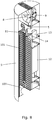
- FIG. 1 shows schematically a discharge electrode 11 which is designed to be arranged within an electrostatic precipitator (ESP) system on a chimney of e.g. a wood combustion stove in order to remove the particulate matter from the flue gasses from wood combustion.
- the discharge electrode 11 comprises a discharge electrode connector 204, which is connected to a high voltage generator, when the system is in use.
- the high voltage generator provides for an electric field being generated in a region around the discharge electrode, when the high voltage generator is turned on; this system will be described below.
- the discharge electrode 11 comprises a first wire connector 201 and a second wire connector 202, which are connected to and separated a distance apart by a support rod 203.
- the distance between the first and second wire connectors 201,202 may be 50 to 300 mm shorter than the vertical length of the collection electrode of an ESP system wherein the electrode is to be used, such as 100-200 mm shorter.
- a discharge electrode 11 wherein the distance between the first and second wire connectors 201,202 was of such a dimension has been tested in the development of the present invention, but other dimensions are also covered by the scope of the claims.
- the discharge electrode connector 204 is attached to the support rod 203 and located at a distance from the first and second wire connectors 201,202.
- the optimum location of the discharge electrode connector 204 will depend on a number of parameters and possible further characteristics of the system in which the discharge electrode is to be used.
- the discharge electrode 11 has ten wires 205 suspended between the first and second wire connectors 201,202, but a discharge electrode 11 according to the invention may have more or less than ten wires suspended between the first and second wire connectors.
- the wires 205 may have a characteristic width of 0.20 - 3.0 mm, such as 0.30 - 1.0 mm, such as 0.35 - 0.45 mm. Wires having a diameter of 0.40 mm have been successfully used in the discharge electrode shown in figure 1 arranged in an ESP system as shown in figure 7 .
- the optimum dimensions of the wires 205 will depend on a number of parameters and possible further characteristics of the system. Theoretically, using thinner wires increases the maximum electric field generated by a wire, but too thin wires may deteriorate quickly and break down. Thus, an optimal size is to be chosen taking these things into account.
- the first and second wire connectors 201,202 are disks each of which are shaped substantially as a circular segment. Furthermore, in the discharge electrode in figure 1 , the first end 206 of the support rod 203 is mounted within a central region of the first wire connector 201 and a second end 207 of the support rod 203 is mounted within a central region of the second wire connector 202 with the wires 205 arranged around the support rod 203. In the illustrated discharge electrode, the wires 205 are situated at the edges of the first and second wire connectors 201,202 and distributed around the circumference of the disks with the wires 205 being substantially parallel to the support rod 203.
- Figure 2 shows schematically parts of the discharge electrode 11 in figure 1 .
- a central mounting of the support rod 203 on the disks shaped substantially as circular segments as well as the distribution of the ten wires 205 around the circumference of the disks is shown in greater detail than in figure 1 .
- the ten wires 205 are not all distributed evenly, i.e. at equal distance to each other.
- the four wires 205 in the first layer around the support rod 203 have the same distance from the support rod 203, and the four wires in next layer have the same distance from the wires 205 in the first layer.
- the two last wires 205 are on the corners of the disk and the same distance from the second layer.
- the discharge electrode connector 204, the first and second wire connectors 201,202, the support rod 203, and the wires 205 are all made of or comprise electrically conductive material.
- the electric field can be controlled to provide a more optimized flow of the flue gas and the charged particles and thereby a resulting more efficient collection of the particles as was described in further details above.
- the parts mentioned as being part of the discharge electrode may e.g. be made of corrosion-resistant material throughout or be made from another material having an outer coating of corrosion resistant material. They may also be made of different corrosion-resistant materials.
- Figure 3 shows schematically an embodiment of an electrostatic precipitator (ESP) system 1 according to the present invention.
- Figure 3.a shows a top view
- figure 3.b shows a cross-sectional view along section A-A in figure 3.a
- Figure 3.c shows a partial cross-sectional view of the insulator; see further description below.
- the system 1 is designed to be arranged on a chimney of e.g. a wood combustion stove in order to remove the particulate matter from the flue gasses from the wood combustion. However, it can also be used for other applications where it is desired to remove particles from a flue gas.
- the ESP system comprises a flue gas inlet 2 for receiving a flow of flue gas, a flue gas outlet 3 for venting the flow of flue gas, and a flow passage 4 extending between the flue gas inlet 2 and the flue gas outlet 3. At least a part of the flow passage 4 is delimited by a collection plate 5 made from or comprising an electrically conductive material. This collection plate 5 forms the collection electrode of the ESP.
- Figure 4 shows schematically how particles in an electric field around a discharge electrode 11 become charged and move towards the grounded collection electrode here in the form of a collection plate 5 where they are accumulated.
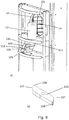
- FIG 5 A possible design of the collection plate 5 for use in an ESP system 1 according to the invention is shown in figure 5 . It comprises a flat shape which extends into a curved shape to form a tubular cylinder segment. This shape is particularly interesting in an embodiment of the invention as shown in figure 6 , where parts of the system to be protected from the high temperatures in the flue gas are arranged in a separate second compartment 7 also being of a tubular cylinder segment and forming a protective shielding.
- the first matching compartment 6 is established either by the collection plate 5 itself, or by an outer housing surrounding the collection plate.
- the ESP system 1 may be of a type having a forced draft obtained by arranging a motor-driven impeller 8 upstream of the outlet 3; such an embodiment is shown schematically in figure 7 .
- the motor 9 for driving the impeller 8 can be arranged in the second compartment 7. As shown in figures 6 and 7 , there is an air gap 10 between the two compartments to improve the protection of the electronics, the motor and the high voltage generator from the hot flue gas.
- the ESP system 1 comprises a discharge electrode 11 as described above.
- the discharge electrode 11 is connected to a voltage generator 12, typically a high voltage generator, providing for an electric field being generated around the discharge electrode 11, when the voltage generator is turned on.
- the voltage is in the order of 20 - 50 kV when the system is in use.
- the discharge electrode 11 is arranged inside the part of the flow passage 4 being delimited by the collection plate 5 so that a strong electric field is established in the flow passage 4 causing the flue gas around the discharge electrode 11 to become ionized as described above.
- a high voltage generator 12 is arranged in the second compartment 7. The ionization of the flue gas releases electrons that charge the particles present in the flue gas. The charged particles are pushed toward the collection plate 5 due to the same polarity electric field as shown in figure 4 ; here they precipitate and stay until they are removed by the automatic cleaning or burning as described above.
- the discharge electrode connector 204 of the discharge electrode 11 is further connected to an insulator 13 arranged between the high voltage generator 12 and the discharge electrode 11. In the illustrated embodiment, this connection is made via a high voltage connector 14.
- the high voltage connector 14 passes partly through the insulator 13 as shown in figure 3.c .
- the discharge electrode connector 204 of the illustrated embodiment is a tube that can slide over the high voltage connector 14.
- the rod-shaped high voltage connector 14 can be fastened inside the discharge electrode connector 204 e.g. by screwing a screw through the discharge connector 204 that then reaches the high voltage connector 14 inside it.
- the insulator 13 is arranged between the discharge electrode 11 (negative polarity) and where the insulator 13 is mounted on the body of the ESP (grounded - positive polarity). It prevents the shortcut between two poles (i.e. the discharge electrode and the collection electrode). As shown schematically in figure 3.c , a high voltage cable 15 passes through the insulator 13 and connects to the high voltage connector 14, and the other end of this cable 15 is connected to the high voltage generator 12.
- FIG 8 shows schematically a cross-sectional, partial view of another embodiment of an ESP system according to the present invention.
- the system resembles the one shown in the previous figures and further comprises a grid 101 being arranged inside the part of the flow passage 4 delimited by the collection plate 5.
- the grid 101 is shaped such that it extends along and at a distance from the collection plate 5.
- the grid 101 comprises an electrically conductive material, and the grid 101 and the collection plate 5 together form the collection electrode of the ESP system 1.
- the collection plate can be considered as a primary collection electrode, and the grid can be considered a secondary collection electrode.
- the grid 101 which is arranged in the part of the flow passage 4 delimited by the collection plate 5 comprises a mesh-like structure.
- the grid 101 is in the form of a mesh, but it could also be a plate with holes.
- the mesh-like structure of the grid 101 is of an electrically conductive material. The particles are collected both on the grid 101 and on the collection plate 5, and as described above, this arrangement significantly improves the efficiency of the ESP compared to similar known systems without such a grid.
- Both the collection plate 5 and the grid 101 can be made from low or medium carbon steel; it can also be made from stainless steel or alloy steel to obtain a higher corrosion resistance.
- a characteristic of some embodiments of the present invention is a build-in possibility of regularly cleaning the collection electrode by removing the particles collected thereon in order to improve the efficiency of the ESP.
- This cleaning can be performed by the system itself so that a chimneysweeper does not need to have direct access in order to perform the cleaning e.g. by use of a brush as is of the case in known systems.
- the cleaning can be performed regularly, such as daily, and not just once or twice a year as is typically the case with traditional systems.
- FIG. 9a shows schematically an example of such an actuator 112 in the form of an electric motor 104 having an eccentric cam 105 mounted on a shaft 106 which can be rotated by the electric motor 104.
- the cam 105 when seen along the axis of rotation is shown in figure 9.b . It has a shape that is generally rectangular with two rounded corners 107, the rounded corners 107 being opposite each other in both directions, such that the slope of the rounded corners 107 extends to a sharp edge 108.
- This shape with two sharp edges 108 has the effect of causing the grid 101 to drop as soon as the contacting means, see below, clear the sharp edge 108. This results in the most efficient accelerating effect due to gravity and thereby a high impact force when the grid 101 hits an internal bottom structure 109; see figure 7 .
- the grid 101 has a contacting means which extends from the grid 101.
- the contacting means is illustrated as a pin 110 arranged on the flat side surface of the grid 101 which pin 110 goes out through a slit 111 in the collection plate 5.
- the electrical motor 104 with low rotational speed, such as below 180 rpm, causes the double-eccentric cam 105 to move the grid 101 upward.
- the dimensions of the cam 105 were so that the upward movement of the grid 101 was about 25 mm. After being moved upwards, the grid 101 drops from this height due to gravity resulting in the grid 101 impacting on the internal bottom structure 109 of the ESP system 1.
- This internal bottom structure 109 is typically also a supporting base for the grid 101 when it is not being moved; i.e. when no cleaning due to impact is performed. In addition to the impacting action, cleaning is also established by friction between particles on the grid 101 and on the collection plate 5.
- the distance between the grid 101 and the collection plate 5 should preferably be chosen so that this friction is large enough to detach particles and low enough to allow the grid 101 to fall fast enough to impart the impact resulting in further removal of particles from the grid 101.
- every rotation of the motor 104 slides the grid 101 twice against the collection plate 5, and correspondingly the grid 101 falls on the internal bottom structure 109 twice. Every time the grid 101 hits the internal bottom structure 109, its impact helps to shake the particles off the grid 101.
- the cleaning process involving the movement of the grid is preferably activated when the ESP is cold and the high voltage generator 12 is shut off to prevent elutriation of the detached particles and prompt free fall of the particles, respectively.
- the ESP is hot, where there is hot flue gas in the chimney with the high voltage generator 12 turned on to prevent the detached particles from leaving the ESP to the outside.
- Embodiments of the ESP system 1 having an actuator 112 preferably further comprises a control system (not shown), which controls when the actuator 112 is in operation and for how long; i.e. that the actuator 112, when in operation, runs for a period of time during which the grid is moved.
- a control system not shown
- each of the first and second wire connectors 201,202 has a shape in the horizontal plane corresponding to that of a horizontal cross-section of the flow passage delimited by the collection plate 5 in figure 5 when viewed in the vertical direction.
- a uniform electric field extending between the discharge electrode 11 and the collection plate 5 or collection electrode will result in a well-distributed corona discharge across the space between the collection electrode and the discharge electrode.
- a discharge electrode having either crossing plates (with e.g. straight edges, saw-tooth edges, or square-edged), circular wire connectors or single rods and wires, all of which resulted in a non-uniform electric field extending between the discharge electrode and the collection plate 5, was tested.
- crossing plates with e.g. straight edges, saw-tooth edges, or square-edged
- circular wire connectors or single rods and wires, all of which resulted in a non-uniform electric field extending between the discharge electrode and the collection plate 5
- the discharge electrode could advantageously be designed to have a matching shape in a manner shown above for a presently preferred design.
- Figure 10 shows the electric potential distribution around a discharge electrode 11 made according to the present invention and tested in a system as in figure 8 .
- the matching design of the discharge electrode and the cross-section of the flow passage delimited by the collection plate 5 gave rise to a homogeneous electrical field. This has been found to give an efficient removal of particles, since they can be evenly collected over the whole inner surface of the collection electrode.
Abstract
Description
- The present invention relates to electrostatic precipitator systems, and in particular to such systems having means for improved removal of the ultrafine particles present in flue gas from e.g. wood combustion stoves.
- Wood is an important raw material that contains energy and grows by absorbing CO2 from the air, solar energy and water. Furthermore, wood is CO2 neutral as it absorbs as much CO2 when it grows as it emits when it is burned or decaying in nature. Wood is thus renewable energy and an important source of energy, and it should therefore be burned off e.g. to provide heating of residential houses.
- However, a disadvantage of wood combustion is the formation of ultrafine particles of which the vast majority are in the range of 0.01 µm (10 nanometres) to 0.4 µm (400 nanometres). Ultrafine particles are harmful to human beings, because they are not filtered out by the nose and bronchioles and instead enter deep into the lungs from where they can be absorbed directly into the blood stream. This is known to cause a number of adverse health effects.
- Particle matter emissions from wood stoves consist of three main types of particles: condensable organic compounds (COC), elemental carbon (soot), and inorganic compounds (ash). These three types have very different resistivities. Particle resistivity plays an important role in the charging and precipitation of the particles by an electrostatic precipitator (ESP); see below. These particles are dry solid particles. Some of the emissions are initially gaseous, but they convert to solid particles as the temperature in the aerosol drops, enabling them to be precipitated.
- A known method of reducing the number of fine and ultrafine particles in an aerosol or a flow of flue gas is the use of an electrostatic precipitator (ESP), wherein an electric field causes the aerosol or flue gas around the discharge electrode to become ionized. Hereby either free electrons or charged gas molecules become trapped on the particles and thereby charge the particles. The charged particles are repulsed from the discharge electrode towards a grounded collection electrode on which they settle and build up.
- The electric field in an ESP is generated by a discharge electrode connected to a high voltage generator which ionizes the gas in its surroundings and as a result charges the particles and delivers an electric field strong enough to push the charged particles towards a collection electrode. While the electric field is on, the precipitated particles will remain attached to the collection electrode. At intervals, it is necessary to clean the collection electrode, thereby removing the particles precipitated thereon, in order to keep the system running efficiently. Such a cleaning is e.g. done by a chimneysweeper using a brush.
- Different types of discharge electrodes are utilized for ESPs, such as e.g. thin wires, wires with crossing pins, barbed wires, wire springs, pipes, rigid frames, and plates. The discharge electrode design depends on various factors including the process for which the ESP is applied, properties of the flue gas and the particles contained therein.
- An example of an ESP comprising multiple wire segments and a high voltage electrode is known from
US2001/0020417 . The wire segments are positioned within a surrounding electrically conductive porous media constituting the collection electrode. The wires are positioned to extend in a direction along the longitudinal axis of the porous media. The ESP relies on droplets such as oil and grease or added water to carry the solid particles away from the collection electrode to prevent build-up and clogging of the porous media. This can cause problems with the disposing the particle-containing water/grease/oil. - It is another object of the present invention to provide an ESP system in which it is more efficient to remove the collected particles than in known systems.
- It is an object of at least some embodiments of the present invention to provide an ESP system which keeps its collection efficiency over time.
- It is a further object of the present invention to provide an alternative to the prior art.
- Thus, the above-described objects and several other objects are intended to be obtained by providing an electrostatic precipitator system for dry particle precipitation, the system comprising:
- a flue gas inlet for receiving a flow of flue gas,
- a flue gas outlet for venting the flow of flue gas,
- a flow passage extending between the flue gas inlet and the flue gas outlet, part of the flow passage being delimited by a collection plate, the collection plate comprising an electrically conductive material,
- a high voltage generator, and
- a discharge electrode comprising:
- a discharge electrode connector, which is connected to the high voltage generator, the high voltage generator providing for an electric field being generated in a region around the discharge electrode when the high voltage generator is turned on, and
- a first and a second wire connectors, which are connected to and separated a distance apart by a support rod, the first and second wire connectors having at least one wire suspended between them,
wherein the discharge electrode connector, the first and second wire connectors, the support rod, and the at least one wire all comprise electrically conductive material,
- goes through an insulator arranged between the high voltage generator and the discharge electrode, or
- is provided with other insulator means configured to hold the discharge electrode and prevent shortcutting of the system when the high voltage generator is turned on.
- Even though the words "support rod" and "wire connector" may give the impression that these parts are merely performing a holding function, that is not the case. They constitute important functional parts of the discharge electrode as they contribute to the desired electric field.
- The discharge electrode being connected to a high voltage generator via the discharge electrode connector causes an electric field to be generated around the support rod, the wire connectors and the one or more wires when the system is turned on. The electric fields generated in this way produce a resultant electric field. Since all these components are made from electrically conductive material, by changing the shape of the wire connectors, the position of the support rod, and the number and positions of the wires suspended there between, the shape of the resultant electric field can be altered to suit the requirements of a system in which the discharge electrode is to be used. It is thus an advantage of the present invention that the resultant electric field generated around the discharge electrode can be shaped to suit the needs of a given setup. Some particularly preferred embodiments will be described in further details below.
- Gas ions and free electrons charge the particles, and, if the strength of the electric field and the particle saturation is optimal, the charged particles are pushed towards the collection electrode, such as the collection plate, on which they settle and build up. At intervals, it is necessary to clean the collection electrode, thereby removing the particles precipitated thereon, in order to keep the system running efficiently.
- The collection plate may be made of low or medium carbon steel. It may be advantageous to use stainless steel or alloy steel to obtain a higher corrosion resistance. Corrosion resistance is desirable both due to the flue gas and particles properties and due to the sparks which can occur due to the high voltage electric field.
- Here and in the following, "connectable" or "connected" does not necessarily mean that the two respective components touch each other. The connection may be established via other components, and the connection will typically be either mechanical or electrical. Examples of the different connections will be described in relation to the figures.
- The first and second wire connectors being "separated a distance apart" means that there is space in-between them so that they are not in direct contact except via the support rod and the wires. The support rod ensures stability along the length of the discharge electrode and keeps the wires suspended. Furthermore, since the support rod is made from electrically conductive material, it influences the electrical field of the ESP.
- By at least one wire being "suspended" between the first and second wire connectors is meant that the at least one wire is somehow attached to and kept in position by the first and second wire connectors. Thus, the at least one wire extends from the first wire connector to the second wire connector.
- In the case of a plurality of wires being suspended between the first and second wire connectors, this may be achieved by using a single length of wire or a number of lengths of wire less than or equal to the number of wires referred to in the plurality of wires. For such embodiments having a plurality of wires, the first and second wire connectors may each comprise two or more holes through which the one or more lengths of wire may be threaded to provide the plurality of wires suspended between the first and second wire connectors. When more lengths of wire are used, each of them may constitute a wire extending between the first and second wire connectors and being fastened at both ends.
- In a presently preferred embodiment of the invention, the first and second wire connectors are shaped identically. In alternative embodiments, the first and second wire connectors have different sizes. The latter may e.g. be relevant, if the cross-section of the flow path within the surrounding collection plate is not constant.
- In some embodiments of the invention, the at least one wire comprises a corrosion-resistant material. It may e.g. be made of corrosion-resistant material throughout its thickness. It may also be made from another material having an outer coating of corrosion resistant material.
- In applications, where the discharge electrode is subjected to e.g. flue gas containing corrosive material, using stainless steel, such as SS304, as a corrosion-resistant material is an option. Depending on the properties of the environment, such as e.g. temperature, moisture and particles in the surroundings, stainless steel or carbon steel (about and below 0.5% carbon) may be used as corrosion-resistant material.
- In some embodiments of the invention, the at least one wire has a characteristic width of 0.20 - 3.0 mm, such as 0.30 - 1.0 mm, such as 0.35 - 0.45 mm. A characteristic width could be a diameter of a wire with a circular cross-section. The actual characteristic width to use for a given system comprising a discharge electrode will depend on a number of parameters and possible further characteristics of the system. In some of the ESP systems tested during the development of the present invention, the wires had a width of 0.3 to 0.6 mm, and the first and second wire connectors were horizontally arranged disks with a thickness of 2 to 4 mm. However, other dimensions are also covered by the scope of the present invention and will have to be determined for a given application, such as for a given overall size of the ESP system in which the discharge electrode is used.
- The thin wires generate a plasma region around their perimeter throughout the length of the wires, in contradiction to plate-shaped discharge electrodes where the plasma generation is mostly limited to the edges. Besides, the distribution of the electric field on the surfaces of a plate-shaped discharge electrode results in strong cross-sectional flow, sometimes called ion wind, which should be prevented to minimize detachment of the already precipitated particles. This is related to the small distance between the discharge electrode and the collection electrode. Therefore, for small scale ESPs thin wires are considered more efficient than plates both in relation to the collection of the particles and in relation to ensuring that the collected particles stay on the collection electrode until they are intentionally removed during cleaning of the collection electrode.
- In the present invention, the first and second wire connectors made from conductive material are used to obtain a certain amount of turbulence of the electric field which is used to decrease the vertical speed of the flow of flue gas from the inlet to the outlet. Hereby the turbulence which is normally considered as undesired due to the possibly detachment of particles from the collection electrode is actively used to improve the efficiency of the ESP. The turbulence and the resulting decrease in vertical speed makes it possible to give time for more of the particles being charged and make it more likely that the particles change direction and move towards the collection electrode. This design is part of the present invention in that the first and second wire connectors are not just suspending the wires but have a further function in the way they influence the flow of the particles to obtain a higher overall efficiency of the system.
- The distance between the first and second wire connectors may be 50 to 300 mm shorter than the vertical length of the collection electrode of the ESP in which the discharge electrode is to be used, such as 100-200 mm shorter.
- The discharge electrode connector may be attached to the support rod and at a distance from the first and second wire connectors.
- The distance between the first wire connector and the discharge electrode connector may be 20-120 mm, such as 25-100 mm, such as 40-60 mm. The actual distance between the first wire connector and the discharge electrode connector to use for a given system comprising a discharge electrode will depend on a number of parameters and possible further characteristics of the system.
- In the embodiments tested, this distance was 50 mm from the first wire connector located at the top of the discharge electrode. Different mounting configurations were tested and this one showed a good precipitation efficiency as well as a good removal of the collected particles by self-ignition of the collected particles.
- In some embodiments of the invention, the discharge electrode comprises a plurality of wires, a first end of the support rod is mounted within a central region of the first wire connector, and a second end of the support rod is mounted within a central region of the second wire connector such that the plurality of wires can be arranged around the support rod. An example of such an embodiment will be shown in the figures.
- By the support rod being "mounted within a central region" of the first wire connector and of the second wire connector is meant any configuration that will allow for a plurality of wires to be arranged around the support rod. This will allow for an expanded electrical potential distribution due to the location of the wires when compared to a discharge electrode without such wires.
- In some embodiments of the invention, the first and second wire connectors are shaped as disks. By "disk" is meant that one dimension, often referred to as the thickness, of the wire connector is significantly smaller than the other two dimensions of the wire connector such that the wire connector has a flat shape.
- The first and second wire connectors may be disks each of which are shaped substantially as a circular segment. A circular segment is a portion of a circular disk, where one edge is a circular arc and another edge is a chord, i.e. a straight line joining two points on a circle. Another way to describe a circular segment is that it is the shape obtained by cutting off part of a circle from the rest of the circle, wherein the cut is a straight line between two points on the circle. Alternatively, the first and second wire connectors may have another shape, preferably corresponding to the shape of the collection plate. It could e.g. be shaped with part of the circumference being part of a circle and the other part being any connecting line, such as a bent or curved line matching the non-circular part of the collection plate.
- By "shaped substantially as a circular segment" is meant that the shape may be further adjusted in minor ways, while the overall shape resembles a circular segment. For instance, a wire connector may be initially shaped as a circular segment and then have the two sharp edges between the circular arc and the chord rounded off.
- In some embodiments of the invention, the discharge electrode comprises a plurality of wires, wherein the wires are fastened at or near an edge of the first and second wire connectors and the wires are distributed around the circumference of the disks.
- By "at an edge" is meant any edge of the disk shaped wire connector. The plurality of wires may be distributed evenly or unevenly around the circumference of the disks.
- The at least one wire may be parallel to the support rod. By "parallel" is meant that the at least one wire and the support rod extend in the same direction within accepted tolerances due to the production method used. In embodiments with the first and second wire connectors being of different sizes, the at least one wire will typically not be parallel to the support rod.
- In some embodiments of the invention, each of the first and second wire connectors has a shape in the horizontal plane corresponding to that of a horizontal cross-section of the flow passage delimited by the collection plate when viewed in the vertical direction. By "horizontal" and "vertical" is referred to the system being arranged in a vertical chimney. If the chimney and thereby also the ESP system are arranged at another angle, the relevant planes will be perpendicular and parallel, respectively, to the main flow direction. By shaping the first and second wire connectors in this way, the wires may be suspended between the two wire connectors such that, in combination with positioning of the discharge electrode within the flow passage delimited by the collection plate forming the collection electrode, a uniform electric field extending between the discharge electrode and the collection electrode may be achieved. This is obtained by the possibility of having a substantially equal distance between the wires and the collection electrode.
- Such a configuration, with a uniform electric field extending between the discharge electrode and the collection electrode, will result in a well-distributed corona discharge across the space between the collection electrode and the discharge electrode; i.e. over the cross section of the flue gas passage. Besides, the wires as a source of the corona discharge are located with an even distance from the collection electrode resulting in an almost uniform delivery of electrons and gas ions to the flue gas. Hereby a more uniform collection over the whole inner surface of the collection plate forming the collection electrode can be obtained. If the system is not designed to ensure such a uniform electrical field, a larger current intensity could arise at the positions with a shorter distance between the discharge electrode and the collection electrode. Hereby the efficiency would be lower at other positions resulting an overall lower efficiency of the system.
- In an ESP system according to an embodiment of the invention, a voltage of 20 - 50 kV, such as 25 - 40 such as 25 - 35 kV, is generated by the voltage generator, when the system is in use.
- In a further embodiment, the distance between the first and second wire connectors is 100 - 200 mm shorter than the vertical length of the collection electrode.
- In some embodiments of the invention, the ESP system further comprises a grid being arranged within the collection plate, the grid comprising a mesh-like structure, such as a mesh or a plate with holes, the mesh-like structure of the grid being made of an electrically conductive material, and the grid being dimensioned, shaped and arranged such that it extends along and at a distance from the collection plate, and the grid and the collection plate together forming a collection electrode. By the grid being arranged "within the collection plate" is preferably meant that it is arranged in the part of the flow passage being delimited by the collection plate. In such embodiments comprising a grid, the collection plate can be considered a primary collection electrode, and the grid can be considered a secondary collection electrode.
- Studies made during the development of the present invention have shown that the arranging of a secondary collection electrode in the form of a grid within the collection plate improves the efficiency of the ESP significantly compared to similar known systems wherein the charged particles in the flue gas are collected only on a single collection electrode, e.g. in the form of a plate, without such a secondary collection electrode, such as a grid as in some embodiments of the present invention. This increased efficiency is related to the presence of the secondary collection electrode in the form of the grid causing a reduction in the strength of the field at the primary collection electrode enough to lower the risk of re-entrainment of the precipitated particles. It is also related to the fact that the particles are collected both on the grid and on the collection plate giving a larger surface area of collection. Furthermore, the mesh-like structure has been found to be an efficient particle collector as it assists in precipitation of the particles.
- Studies made in relation to the present invention have also shown that the grid in combination with a discharge electrode as described above results in self-ignition and burn off of the collected particles and correspondingly self-cleaning of the ESP. It has been observed that the primary sparks are heading toward the grid wires. These sparks provide local high temperature zones that can ignite and burn off the particles on the collection plate and on the grid. This burn off process typically takes place at least once in each combustion cycle of the wood combustion stove at a specific temperature, flue gas oxygen level and thickness of the layer of collected particles. Thus, having a grid arranged within the collection plate of an ESP system will improve the efficiency of the ESP significantly.
- The mesh-like structure of the grid may comprise openings with a vertical dimension of 15-30 mm, such as 18-25 mm, such as 20-22 mm, and a horizontal dimension of 15-30 mm, such as 18-25 mm, such as 20-22 mm. The vertical and horizontal dimensions may be the same or different. By "vertical" and "horizontal", reference is made to the system when installed on a chimney, typically extending from a wood combustion stove. This typically means that the inlet is facing downwards and the outlet is facing upwards.
- An ESP system comprising such a grid may further comprise an actuator for, when the actuator is in operation, providing an upwards force so as to move the grid upwards, so that the grid, after being moved upwards, drops from a height due to gravity resulting in the grid impacting on an internal bottom structure of the electrostatic precipitator system.
- The mechanical movements of the grid relative to the collection plate initially result in detachment of some of the precipitated particles on the collection plate. When the grid drops on the internal bottom structure, such as a base of the collection plate, the particles are detached from the grid due to the impact and fall down the chimney from where they burn or can be removed. By "internal bottom structure" is meant something onto which the grid can drop so that the downwards movement is stopped fast enough to apply the impact that will cause at least a majority of the particles to fall off the grid in order to provide the cleaning.
- The different aspects of the present invention as described above may each be combined with any of the other aspects as long as it is physically possible. These and other aspects of the invention will be apparent from and elucidated with reference to the embodiments described hereinafter.
- The electrostatic precipitator (ESP) system according to the invention will now be described in more detail with regard to the accompanying figures. The figures show one way of implementing the present invention and is not to be construed as being limiting to other possible embodiments falling within the scope of the attached claim set.
-
Figure 1 shows schematically a discharge electrode for use in an embodiment of an ESP system according to the present invention. -
Figure 2 shows a closer view of parts of the discharge electrode infigure 1 . -
Figure 3 shows schematically an embodiment of an electrostatic precipitator system according to the present invention.Figure 3.a shows a top view, andfigure 3.b shows a cross-sectional view along section A-A infigure 3.a .Figure 3.c shows a partial cross-sectional view of the region around the insulator. -
Figure 4 shows schematically how particles in an electric field around a discharge electrode become charged and move towards a collection electrode. -
Figure 5 shows schematically a possible design of the collection plate for use in an ESP system according to the present invention. -
Figure 6 shows schematically an ESP system having two compartments each being in the form of a tubular cylindrical segment. -
Figure 7 shows schematically a three-dimensional, cross-sectional partial view of an embodiment of the invention. -
Figure 8 shows schematically a three-dimensional, cross-sectional partial view of another embodiment of the invention comprising a cleaning grid arranged in the flow passage. -
Figure 9 shows schematically a part of a system according to an embodiment of the invention.Figure 9.a shows the system comprising a grid which is movable by an actuator.Figure 9.b shows the cam of the actuator. -
Figure 10 shows the electric potential distribution around a discharge electrode made according to the present invention and tested in a system as infigure 8 . -
Figure 1 shows schematically adischarge electrode 11 which is designed to be arranged within an electrostatic precipitator (ESP) system on a chimney of e.g. a wood combustion stove in order to remove the particulate matter from the flue gasses from wood combustion. Thedischarge electrode 11 comprises adischarge electrode connector 204, which is connected to a high voltage generator, when the system is in use. The high voltage generator provides for an electric field being generated in a region around the discharge electrode, when the high voltage generator is turned on; this system will be described below. - The
discharge electrode 11 comprises afirst wire connector 201 and asecond wire connector 202, which are connected to and separated a distance apart by asupport rod 203. The distance between the first and second wire connectors 201,202 may be 50 to 300 mm shorter than the vertical length of the collection electrode of an ESP system wherein the electrode is to be used, such as 100-200 mm shorter. Adischarge electrode 11 wherein the distance between the first and second wire connectors 201,202 was of such a dimension has been tested in the development of the present invention, but other dimensions are also covered by the scope of the claims. - The
discharge electrode connector 204 is attached to thesupport rod 203 and located at a distance from the first and second wire connectors 201,202. The optimum location of thedischarge electrode connector 204 will depend on a number of parameters and possible further characteristics of the system in which the discharge electrode is to be used. - In the discharge electrode shown in
figure 1 , thedischarge electrode 11 has tenwires 205 suspended between the first and second wire connectors 201,202, but adischarge electrode 11 according to the invention may have more or less than ten wires suspended between the first and second wire connectors. Thewires 205 may have a characteristic width of 0.20 - 3.0 mm, such as 0.30 - 1.0 mm, such as 0.35 - 0.45 mm. Wires having a diameter of 0.40 mm have been successfully used in the discharge electrode shown infigure 1 arranged in an ESP system as shown infigure 7 . However, the optimum dimensions of thewires 205 will depend on a number of parameters and possible further characteristics of the system. Theoretically, using thinner wires increases the maximum electric field generated by a wire, but too thin wires may deteriorate quickly and break down. Thus, an optimal size is to be chosen taking these things into account. - In the discharge electrode in
figure 1 , the first and second wire connectors 201,202 are disks each of which are shaped substantially as a circular segment. Furthermore, in the discharge electrode infigure 1 , thefirst end 206 of thesupport rod 203 is mounted within a central region of thefirst wire connector 201 and asecond end 207 of thesupport rod 203 is mounted within a central region of thesecond wire connector 202 with thewires 205 arranged around thesupport rod 203. In the illustrated discharge electrode, thewires 205 are situated at the edges of the first and second wire connectors 201,202 and distributed around the circumference of the disks with thewires 205 being substantially parallel to thesupport rod 203. -
Figure 2 shows schematically parts of thedischarge electrode 11 infigure 1 . A central mounting of thesupport rod 203 on the disks shaped substantially as circular segments as well as the distribution of the tenwires 205 around the circumference of the disks is shown in greater detail than infigure 1 . In the discharge electrode infigures 1 and2 , the tenwires 205 are not all distributed evenly, i.e. at equal distance to each other. The fourwires 205 in the first layer around thesupport rod 203 have the same distance from thesupport rod 203, and the four wires in next layer have the same distance from thewires 205 in the first layer. The twolast wires 205 are on the corners of the disk and the same distance from the second layer. - The
discharge electrode connector 204, the first and second wire connectors 201,202, thesupport rod 203, and thewires 205 are all made of or comprise electrically conductive material. By having all the parts made from or comprising electrically conductive material, the electric field can be controlled to provide a more optimized flow of the flue gas and the charged particles and thereby a resulting more efficient collection of the particles as was described in further details above. The parts mentioned as being part of the discharge electrode may e.g. be made of corrosion-resistant material throughout or be made from another material having an outer coating of corrosion resistant material. They may also be made of different corrosion-resistant materials. -
Figure 3 shows schematically an embodiment of an electrostatic precipitator (ESP)system 1 according to the present invention.Figure 3.a shows a top view, andfigure 3.b shows a cross-sectional view along section A-A infigure 3.a .Figure 3.c shows a partial cross-sectional view of the insulator; see further description below. Thesystem 1 is designed to be arranged on a chimney of e.g. a wood combustion stove in order to remove the particulate matter from the flue gasses from the wood combustion. However, it can also be used for other applications where it is desired to remove particles from a flue gas. The ESP system comprises aflue gas inlet 2 for receiving a flow of flue gas, aflue gas outlet 3 for venting the flow of flue gas, and aflow passage 4 extending between theflue gas inlet 2 and theflue gas outlet 3. At least a part of theflow passage 4 is delimited by acollection plate 5 made from or comprising an electrically conductive material. Thiscollection plate 5 forms the collection electrode of the ESP. -
Figure 4 shows schematically how particles in an electric field around adischarge electrode 11 become charged and move towards the grounded collection electrode here in the form of acollection plate 5 where they are accumulated. - A possible design of the
collection plate 5 for use in anESP system 1 according to the invention is shown infigure 5 . It comprises a flat shape which extends into a curved shape to form a tubular cylinder segment. This shape is particularly interesting in an embodiment of the invention as shown infigure 6 , where parts of the system to be protected from the high temperatures in the flue gas are arranged in a separatesecond compartment 7 also being of a tubular cylinder segment and forming a protective shielding. Thefirst matching compartment 6 is established either by thecollection plate 5 itself, or by an outer housing surrounding the collection plate. By suitable dimensioning and arranging the two tubular cylinder segments, it is possible to obtain the overall appearance of a cylinder. In the embodiments infigure 5 and the following figures, the flat part of thecollection plate 5 as well as the flat part of thesecond compartment 7 and the flat part of thefirst compartment 6, each comprises alateral opening 16 providing a passage for the components of the system extending between the first and the second compartment. - The
ESP system 1 may be of a type having a forced draft obtained by arranging a motor-drivenimpeller 8 upstream of theoutlet 3; such an embodiment is shown schematically infigure 7 . Themotor 9 for driving theimpeller 8 can be arranged in thesecond compartment 7. As shown infigures 6 and7 , there is anair gap 10 between the two compartments to improve the protection of the electronics, the motor and the high voltage generator from the hot flue gas. - The
ESP system 1 according to the invention comprises adischarge electrode 11 as described above. Thedischarge electrode 11 is connected to avoltage generator 12, typically a high voltage generator, providing for an electric field being generated around thedischarge electrode 11, when the voltage generator is turned on. In presently preferred embodiments of the invention, the voltage is in the order of 20 - 50 kV when the system is in use. - The
discharge electrode 11 is arranged inside the part of theflow passage 4 being delimited by thecollection plate 5 so that a strong electric field is established in theflow passage 4 causing the flue gas around thedischarge electrode 11 to become ionized as described above. In the embodiment infigure 7 , ahigh voltage generator 12 is arranged in thesecond compartment 7. The ionization of the flue gas releases electrons that charge the particles present in the flue gas. The charged particles are pushed toward thecollection plate 5 due to the same polarity electric field as shown infigure 4 ; here they precipitate and stay until they are removed by the automatic cleaning or burning as described above. - Parts of the ESP system will now be described in further details with reference mainly to
figure 3 . Thedischarge electrode connector 204 of thedischarge electrode 11 is further connected to aninsulator 13 arranged between thehigh voltage generator 12 and thedischarge electrode 11. In the illustrated embodiment, this connection is made via ahigh voltage connector 14. Thehigh voltage connector 14 passes partly through theinsulator 13 as shown infigure 3.c . As shown infigures 1 and2 , thedischarge electrode connector 204 of the illustrated embodiment is a tube that can slide over thehigh voltage connector 14. The rod-shapedhigh voltage connector 14 can be fastened inside thedischarge electrode connector 204 e.g. by screwing a screw through thedischarge connector 204 that then reaches thehigh voltage connector 14 inside it. Theinsulator 13 is arranged between the discharge electrode 11 (negative polarity) and where theinsulator 13 is mounted on the body of the ESP (grounded - positive polarity). It prevents the shortcut between two poles (i.e. the discharge electrode and the collection electrode). As shown schematically infigure 3.c , ahigh voltage cable 15 passes through theinsulator 13 and connects to thehigh voltage connector 14, and the other end of thiscable 15 is connected to thehigh voltage generator 12. -
Figure 8 shows schematically a cross-sectional, partial view of another embodiment of an ESP system according to the present invention. The system resembles the one shown in the previous figures and further comprises agrid 101 being arranged inside the part of theflow passage 4 delimited by thecollection plate 5. Thegrid 101 is shaped such that it extends along and at a distance from thecollection plate 5. Thegrid 101 comprises an electrically conductive material, and thegrid 101 and thecollection plate 5 together form the collection electrode of theESP system 1. The collection plate can be considered as a primary collection electrode, and the grid can be considered a secondary collection electrode. - The
grid 101 which is arranged in the part of theflow passage 4 delimited by thecollection plate 5 comprises a mesh-like structure. In the illustrated embodiment, thegrid 101 is in the form of a mesh, but it could also be a plate with holes. The mesh-like structure of thegrid 101 is of an electrically conductive material. The particles are collected both on thegrid 101 and on thecollection plate 5, and as described above, this arrangement significantly improves the efficiency of the ESP compared to similar known systems without such a grid. Both thecollection plate 5 and thegrid 101 can be made from low or medium carbon steel; it can also be made from stainless steel or alloy steel to obtain a higher corrosion resistance. - A characteristic of some embodiments of the present invention is a build-in possibility of regularly cleaning the collection electrode by removing the particles collected thereon in order to improve the efficiency of the ESP. This cleaning can be performed by the system itself so that a chimneysweeper does not need to have direct access in order to perform the cleaning e.g. by use of a brush as is of the case in known systems. Furthermore, with an
ESP system 1 according to the present invention, the cleaning can be performed regularly, such as daily, and not just once or twice a year as is typically the case with traditional systems. - The cleaning of the collection electrode, consisting of the
collection plate 5 and thegrid 101, is established by anactuator 112 which can provide a force to thegrid 101 to move the grid, when theactuator 112 is in operation.Figure 9.a shows schematically an example of such anactuator 112 in the form of anelectric motor 104 having aneccentric cam 105 mounted on ashaft 106 which can be rotated by theelectric motor 104. Thecam 105, when seen along the axis of rotation is shown infigure 9.b . It has a shape that is generally rectangular with tworounded corners 107, therounded corners 107 being opposite each other in both directions, such that the slope of therounded corners 107 extends to asharp edge 108. This shape with twosharp edges 108 has the effect of causing thegrid 101 to drop as soon as the contacting means, see below, clear thesharp edge 108. This results in the most efficient accelerating effect due to gravity and thereby a high impact force when thegrid 101 hits aninternal bottom structure 109; seefigure 7 . - The
grid 101 has a contacting means which extends from thegrid 101. The contacting means is illustrated as apin 110 arranged on the flat side surface of thegrid 101 whichpin 110 goes out through aslit 111 in thecollection plate 5. In this embodiment of the invention, theelectrical motor 104 with low rotational speed, such as below 180 rpm, causes the double-eccentric cam 105 to move thegrid 101 upward. In tests performed with a prototype of the invention, the dimensions of thecam 105 were so that the upward movement of thegrid 101 was about 25 mm. After being moved upwards, thegrid 101 drops from this height due to gravity resulting in thegrid 101 impacting on theinternal bottom structure 109 of theESP system 1. This internalbottom structure 109 is typically also a supporting base for thegrid 101 when it is not being moved; i.e. when no cleaning due to impact is performed. In addition to the impacting action, cleaning is also established by friction between particles on thegrid 101 and on thecollection plate 5. The distance between thegrid 101 and thecollection plate 5 should preferably be chosen so that this friction is large enough to detach particles and low enough to allow thegrid 101 to fall fast enough to impart the impact resulting in further removal of particles from thegrid 101. - With the illustrated shape of the
cam 105, every rotation of themotor 104 slides thegrid 101 twice against thecollection plate 5, and correspondingly thegrid 101 falls on theinternal bottom structure 109 twice. Every time thegrid 101 hits theinternal bottom structure 109, its impact helps to shake the particles off thegrid 101. - The cleaning process involving the movement of the grid is preferably activated when the ESP is cold and the
high voltage generator 12 is shut off to prevent elutriation of the detached particles and prompt free fall of the particles, respectively. Alternatively, when the ESP is hot, where there is hot flue gas in the chimney with thehigh voltage generator 12 turned on to prevent the detached particles from leaving the ESP to the outside. - Embodiments of the
ESP system 1 having anactuator 112 preferably further comprises a control system (not shown), which controls when theactuator 112 is in operation and for how long; i.e. that theactuator 112, when in operation, runs for a period of time during which the grid is moved. - In the discharge electrode shown in
figures 1 and2 , each of the first and second wire connectors 201,202 has a shape in the horizontal plane corresponding to that of a horizontal cross-section of the flow passage delimited by thecollection plate 5 infigure 5 when viewed in the vertical direction. This makes it possible to have thewires 205 suspended between the two wire connectors 201,202 such that, in combination with positioning of thedischarge electrode 11 within theflow passage 4, a uniform electric field extending between thedischarge electrode 11 and thecollection plate 5 or collection electrode can be achieved. As mentioned above, a uniform electric field extending between thedischarge electrode 11 and thecollection plate 5 or collection electrode will result in a well-distributed corona discharge across the space between the collection electrode and the discharge electrode. - Studies made during the development of the present invention have shown that in an ESP system, a uniform electric field extending between the discharge electrode and the collection electrode gives the best performance of the ESP system. The performance of the ESP system is defined by its effectiveness in reduction of particulate matter emission, the so-called precipitation efficiency. In these tests, the components of the system were arranged so that the resultant electric field extending between the discharge electrode and the collection plate, forming the collection electrode, was a non-uniform electric field. This was obtained by using a collection plate having a flat shape, which further extended into a curved shape to form an open tubular cylinder segment such that a cross-section in the plane orthogonal to the flat shape was shaped as a circular segment as shown in
figure 5 . In such a setup, a discharge electrode having either crossing plates (with e.g. straight edges, saw-tooth edges, or square-edged), circular wire connectors or single rods and wires, all of which resulted in a non-uniform electric field extending between the discharge electrode and thecollection plate 5, was tested. These tests clearly showed that at least for the ESP system tested, the best performance was obtained with a configuration of the discharge electrode as infigure 1 giving rise to a uniform electric field within a collection electrode having a shape like the collection plate infigure 5 . For other shapes of the collection electrode, the discharge electrode could advantageously be designed to have a matching shape in a manner shown above for a presently preferred design. - During the development of the present invention, tests have shown that it is advantageous to use a design wherein the distance between the first and second wire connectors is 100 - 200 mm shorter than the vertical length of the collection electrode.
-
Figure 10 shows the electric potential distribution around adischarge electrode 11 made according to the present invention and tested in a system as infigure 8 . As shown, the matching design of the discharge electrode and the cross-section of the flow passage delimited by thecollection plate 5 gave rise to a homogeneous electrical field. This has been found to give an efficient removal of particles, since they can be evenly collected over the whole inner surface of the collection electrode. - Although the present invention has been described in connection with the specified embodiments, it should not be construed as being in any way limited to the presented examples. The scope of the present invention is set out by the accompanying claim set. In the context of the claims, the terms "comprising" or "comprises" do not exclude other possible elements or steps. In addition, the mentioning of references such as "a" or "an" etc. should not be construed as excluding a plurality. The use of reference signs in the claims with respect to elements indicated in the figures shall also not be construed as limiting the scope of the invention. Furthermore, individual features mentioned in different claims, may possibly be advantageously combined, and the mentioning of these features in different claims does not exclude that a combination of features is not possible and advantageous.
wherein the connection between the discharge electrode and the high voltage generator:
Claims (13)
- An electrostatic precipitator system (1) for dry particle precipitation, the system comprising:- a flue gas inlet (2) for receiving a flow of flue gas,- a flue gas outlet (3) for venting the flow of flue gas,- a flow passage (4) extending between the flue gas inlet (2) and the flue gas outlet (3), part of the flow passage (4) being delimited by a collection plate (5), the collection plate (5) comprising an electrically conductive material,- a high voltage generator, and- a discharge electrode (11) comprising:wherein the discharge electrode (11) is arranged inside the part of the flow passage (4) delimited by the collection plate (5), and- a discharge electrode connector (204), which is connected to the high voltage generator (12), the high voltage generator (12) providing for an electric field being generated in a region around the discharge electrode (11) when the high voltage generator (12) is turned on, and- a first and a second wire connector (201,202), which are connected to and separated a distance apart by a support rod (203), the first and second wire connectors (201,202) having at least one wire (205) suspended between them,
wherein the discharge electrode connector (204), the first and second wire connectors (201,202), the support rod (204), and the at least one wire (205) all comprise electrically conductive material, and
wherein the connection between the discharge electrode (11) and the high voltage generator (12):- goes through an insulator (13) arranged between the high voltage generator (12) and the discharge electrode (11), or- is provided with other insulator means configured to hold the discharge electrode and prevent shortcutting of the system when the high voltage generator is turned on. - An electrostatic precipitator system (1) according to claim 1, wherein the at least one wire (205) has a characteristic width of 0.20 - 3.0 mm, such as 0.30 - 1.0 mm, such as 0.35 - 0.45 mm.
- An electrostatic precipitator system (1) according to any of the previous claims, wherein the distance between the first and second wire connectors (201,202) is 100 - 1000 mm, such as 300 - 800 mm, such as 450 - 650 mm.
- An electrostatic precipitator system (1) according to any of the previous claims, wherein the discharge electrode connector (204) is attached to the support rod (203) and located at a distance from the first and second wire connectors (201,202).
- An electrostatic precipitator system (1) according to any of the previous claims, comprising a plurality of wires (205), wherein a first end (206) of the support rod (203) is mounted within a central region of the first wire connector (201), and a second end (207) of the support rod (203) is mounted within a central region of the second wire connector (202) such that the plurality of wires (205) can be arranged around the support rod (203).
- An electrostatic precipitator system (1) according to any of the previous claims, wherein the first and second wire connectors (201,202) are shaped as disks each of which are shaped substantially as a circular segment.
- An electrostatic precipitator system (1) according to claim 6, comprising a plurality of wires (205), wherein the wires (205) are fastened at or near an edge of the first and second wire connectors (201,202) and the wires (205) are distributed around the circumference of the disks.
- An electrostatic precipitator system (1) according to any of the previous claims, wherein the at least one wire (205) is parallel to the support rod (203).
- An electrostatic precipitator system (1) according to claim 8, wherein each of the first and second wire connectors (201,202) has a shape in the horizontal plane corresponding to that of a horizontal cross-section of the flow passage (4) delimited by the collection plate (5) when viewed in the vertical direction.
- An electrostatic precipitator system (1) according to any of the preceding claims, wherein a voltage of 20 - 50 kV, such as 25 - 40 such as 25 - 35 kV, is generated by the high voltage generator (12), when the system (1) is in use.
- An electrostatic precipitator system (1) according to any of the preceding claims, wherein the distance between the first and second wire connectors (201,202) is 100 - 200 mm shorter than the vertical length of the collection plate (5).
- An electrostatic precipitator system (1) according to any of the preceding claims, further comprising a grid (101) being arranged within the collection plate (5), the grid (101) comprising a mesh-like structure, such as a mesh or a plate with holes, the mesh-like structure of the grid (101) being made of an electrically conductive material, and the grid (101) being dimensioned, shaped and arranged such that it extends along and at a distance from the collection plate (5), and the grid (101) and the collection plate (5) together forming a collection electrode.
- An electrostatic precipitator system (1) according to claim 12, further comprising an actuator (112) for, when the actuator (112) is in operation, providing an upwards force to move the grid (101) upwards, so that the grid (101), after being moved upwards, drops from a height due to gravity resulting in the grid (101) impacting on an internal bottom structure (109) of the electrostatic precipitator system.
Applications Claiming Priority (1)
| Application Number | Priority Date | Filing Date | Title |
|---|---|---|---|
| EP17205176 | 2017-12-04 |
Publications (1)
| Publication Number | Publication Date |
|---|---|
| EP3492174A1 true EP3492174A1 (en) | 2019-06-05 |
Family
ID=60569810
Family Applications (1)
| Application Number | Title | Priority Date | Filing Date |
|---|---|---|---|
| EP18209941.6A Pending EP3492174A1 (en) | 2017-12-04 | 2018-12-03 | Electrostatic precipitator system having a discharge electrode with suspended wire |
Country Status (1)
| Country | Link |
|---|---|
| EP (1) | EP3492174A1 (en) |
Cited By (1)
| Publication number | Priority date | Publication date | Assignee | Title |
|---|---|---|---|---|
| CN116727106A (en) * | 2023-06-16 | 2023-09-12 | 中国重型机械研究院股份公司 | Clamping device and electrode row used after electrode wire breakage |
Citations (5)
| Publication number | Priority date | Publication date | Assignee | Title |
|---|---|---|---|---|
| EP0044361A1 (en) * | 1980-07-18 | 1982-01-27 | Santek Inc. | Electrostatic precipitator comprising a discharge electrode structure |
| US20010020417A1 (en) | 1998-11-25 | 2001-09-13 | Liu Benjamin Y.H. | Compact high efficiency electrostatic precipitator for droplet aerosol collection |
| EP1193445A2 (en) * | 2000-10-02 | 2002-04-03 | Eidgenössische Materialprüfungs- und Forschungsanstalt Empa | Device to clean exhausts from small heating systems |
| EP2108457A2 (en) * | 2008-04-10 | 2009-10-14 | Schiedel AG | Chimney system with electrostatic precipitator |
| US20160288138A1 (en) * | 2015-04-02 | 2016-10-06 | National Chiao Tung University | Electrostatic precipitator structure |
-
2018
- 2018-12-03 EP EP18209941.6A patent/EP3492174A1/en active Pending
Patent Citations (5)
| Publication number | Priority date | Publication date | Assignee | Title |
|---|---|---|---|---|
| EP0044361A1 (en) * | 1980-07-18 | 1982-01-27 | Santek Inc. | Electrostatic precipitator comprising a discharge electrode structure |
| US20010020417A1 (en) | 1998-11-25 | 2001-09-13 | Liu Benjamin Y.H. | Compact high efficiency electrostatic precipitator for droplet aerosol collection |
| EP1193445A2 (en) * | 2000-10-02 | 2002-04-03 | Eidgenössische Materialprüfungs- und Forschungsanstalt Empa | Device to clean exhausts from small heating systems |
| EP2108457A2 (en) * | 2008-04-10 | 2009-10-14 | Schiedel AG | Chimney system with electrostatic precipitator |
| US20160288138A1 (en) * | 2015-04-02 | 2016-10-06 | National Chiao Tung University | Electrostatic precipitator structure |
Cited By (2)
| Publication number | Priority date | Publication date | Assignee | Title |
|---|---|---|---|---|
| CN116727106A (en) * | 2023-06-16 | 2023-09-12 | 中国重型机械研究院股份公司 | Clamping device and electrode row used after electrode wire breakage |
| CN116727106B (en) * | 2023-06-16 | 2024-01-30 | 中国重型机械研究院股份公司 | Clamping device and electrode row used after electrode wire breakage |
Similar Documents
| Publication | Publication Date | Title |
|---|---|---|
| CA2252738C (en) | Electrical dust collector and incinerator | |
| US7077890B2 (en) | Electrostatic precipitators with insulated driver electrodes | |
| CN1791468B (en) | Dust collector | |
| TWI730463B (en) | Method for reducing coupling of electric field | |
| US11185871B2 (en) | Electrostatic precipitator system having a grid for collection of particles | |
| EP3010644B1 (en) | Gas flow cleaning device | |
| AU2008200150A1 (en) | High speed tunnel fan with electrostatic filter | |
| JP2010069360A (en) | Electrostatic dust collector | |
| US20090129993A1 (en) | Apparatus for Treating Exhaust Praticulate Matter | |
| EP3492174A1 (en) | Electrostatic precipitator system having a discharge electrode with suspended wire | |
| KR101183945B1 (en) | Electric Dust Collector | |
| JP2008503343A (en) | Electrostatic filter for tunnel fan | |
| TW201500114A (en) | Electrostatic dust collection device and air cleaning apparatus for preventing electrode from defacing | |
| JP7414819B2 (en) | Device for purification of gaseous media containing particles | |
| JP3118578U (en) | Ionization dust collector with V-shaped ionization space | |
| JP7139120B2 (en) | Electrostatic precipitator | |
| CN214974835U (en) | Electrostatic adsorption type axial flow cyclone air filtering device and system | |
| WO2020241767A1 (en) | Electric dust collector | |
| CN210485830U (en) | Electrostatic insulation structure of oil fume purifier | |
| CN112844840A (en) | Electrostatic adsorption type axial flow cyclone air filtering device and system | |
| RU2333041C1 (en) | Electric precipitator | |
| KR20210098384A (en) | Dust collection system for restaurants | |
| JPS59183843A (en) | Electrostatic dust collecting apparatus |
Legal Events
| Date | Code | Title | Description |
|---|---|---|---|
| PUAI | Public reference made under article 153(3) epc to a published international application that has entered the european phase |
Free format text: ORIGINAL CODE: 0009012 |
|
| STAA | Information on the status of an ep patent application or granted ep patent |
Free format text: STATUS: THE APPLICATION HAS BEEN PUBLISHED |
|
| AK | Designated contracting states |
Kind code of ref document: A1 Designated state(s): AL AT BE BG CH CY CZ DE DK EE ES FI FR GB GR HR HU IE IS IT LI LT LU LV MC MK MT NL NO PL PT RO RS SE SI SK SM TR |
|
| AX | Request for extension of the european patent |
Extension state: BA ME |
|
| STAA | Information on the status of an ep patent application or granted ep patent |
Free format text: STATUS: REQUEST FOR EXAMINATION WAS MADE |
|
| 17P | Request for examination filed |
Effective date: 20191205 |
|
| RBV | Designated contracting states (corrected) |
Designated state(s): AL AT BE BG CH CY CZ DE DK EE ES FI FR GB GR HR HU IE IS IT LI LT LU LV MC MK MT NL NO PL PT RO RS SE SI SK SM TR |
|
| STAA | Information on the status of an ep patent application or granted ep patent |
Free format text: STATUS: REQUEST FOR EXAMINATION WAS MADE |
|
| R17P | Request for examination filed (corrected) |
Effective date: 20191205 |
|
| STAA | Information on the status of an ep patent application or granted ep patent |
Free format text: STATUS: EXAMINATION IS IN PROGRESS |
|
| 17Q | First examination report despatched |
Effective date: 20220518 |