EP3492001A1 - Method of determining an optimum electrode vector length with a retractable muti-use cardiac monitor - Google Patents
Method of determining an optimum electrode vector length with a retractable muti-use cardiac monitor Download PDFInfo
- Publication number
- EP3492001A1 EP3492001A1 EP18203523.8A EP18203523A EP3492001A1 EP 3492001 A1 EP3492001 A1 EP 3492001A1 EP 18203523 A EP18203523 A EP 18203523A EP 3492001 A1 EP3492001 A1 EP 3492001A1
- Authority
- EP
- European Patent Office
- Prior art keywords
- cardiac monitor
- retractable multi
- use cardiac
- data
- monitor
- Prior art date
- Legal status (The legal status is an assumption and is not a legal conclusion. Google has not performed a legal analysis and makes no representation as to the accuracy of the status listed.)
- Withdrawn
Links
Images


Classifications
-
- A—HUMAN NECESSITIES
- A61—MEDICAL OR VETERINARY SCIENCE; HYGIENE
- A61B—DIAGNOSIS; SURGERY; IDENTIFICATION
- A61B5/00—Measuring for diagnostic purposes; Identification of persons
- A61B5/24—Detecting, measuring or recording bioelectric or biomagnetic signals of the body or parts thereof
- A61B5/25—Bioelectric electrodes therefor
-
- A—HUMAN NECESSITIES
- A61—MEDICAL OR VETERINARY SCIENCE; HYGIENE
- A61B—DIAGNOSIS; SURGERY; IDENTIFICATION
- A61B5/00—Measuring for diagnostic purposes; Identification of persons
- A61B5/0002—Remote monitoring of patients using telemetry, e.g. transmission of vital signals via a communication network
- A61B5/0004—Remote monitoring of patients using telemetry, e.g. transmission of vital signals via a communication network characterised by the type of physiological signal transmitted
- A61B5/0006—ECG or EEG signals
-
- A—HUMAN NECESSITIES
- A61—MEDICAL OR VETERINARY SCIENCE; HYGIENE
- A61B—DIAGNOSIS; SURGERY; IDENTIFICATION
- A61B5/00—Measuring for diagnostic purposes; Identification of persons
- A61B5/24—Detecting, measuring or recording bioelectric or biomagnetic signals of the body or parts thereof
- A61B5/316—Modalities, i.e. specific diagnostic methods
- A61B5/318—Heart-related electrical modalities, e.g. electrocardiography [ECG]
- A61B5/332—Portable devices specially adapted therefor
-
- A—HUMAN NECESSITIES
- A61—MEDICAL OR VETERINARY SCIENCE; HYGIENE
- A61B—DIAGNOSIS; SURGERY; IDENTIFICATION
- A61B5/00—Measuring for diagnostic purposes; Identification of persons
- A61B5/24—Detecting, measuring or recording bioelectric or biomagnetic signals of the body or parts thereof
- A61B5/316—Modalities, i.e. specific diagnostic methods
- A61B5/318—Heart-related electrical modalities, e.g. electrocardiography [ECG]
- A61B5/333—Recording apparatus specially adapted therefor
- A61B5/335—Recording apparatus specially adapted therefor using integrated circuit memory devices
-
- A—HUMAN NECESSITIES
- A61—MEDICAL OR VETERINARY SCIENCE; HYGIENE
- A61B—DIAGNOSIS; SURGERY; IDENTIFICATION
- A61B5/00—Measuring for diagnostic purposes; Identification of persons
- A61B5/24—Detecting, measuring or recording bioelectric or biomagnetic signals of the body or parts thereof
- A61B5/316—Modalities, i.e. specific diagnostic methods
- A61B5/318—Heart-related electrical modalities, e.g. electrocardiography [ECG]
- A61B5/339—Displays specially adapted therefor
-
- A—HUMAN NECESSITIES
- A61—MEDICAL OR VETERINARY SCIENCE; HYGIENE
- A61B—DIAGNOSIS; SURGERY; IDENTIFICATION
- A61B2560/00—Constructional details of operational features of apparatus; Accessories for medical measuring apparatus
- A61B2560/04—Constructional details of apparatus
- A61B2560/0443—Modular apparatus
- A61B2560/045—Modular apparatus with a separable interface unit, e.g. for communication
-
- A—HUMAN NECESSITIES
- A61—MEDICAL OR VETERINARY SCIENCE; HYGIENE
- A61B—DIAGNOSIS; SURGERY; IDENTIFICATION
- A61B2562/00—Details of sensors; Constructional details of sensor housings or probes; Accessories for sensors
- A61B2562/22—Arrangements of medical sensors with cables or leads; Connectors or couplings specifically adapted for medical sensors
- A61B2562/221—Arrangements of sensors with cables or leads, e.g. cable harnesses
-
- A—HUMAN NECESSITIES
- A61—MEDICAL OR VETERINARY SCIENCE; HYGIENE
- A61B—DIAGNOSIS; SURGERY; IDENTIFICATION
- A61B5/00—Measuring for diagnostic purposes; Identification of persons
- A61B5/68—Arrangements of detecting, measuring or recording means, e.g. sensors, in relation to patient
- A61B5/6801—Arrangements of detecting, measuring or recording means, e.g. sensors, in relation to patient specially adapted to be attached to or worn on the body surface
- A61B5/6813—Specially adapted to be attached to a specific body part
- A61B5/6823—Trunk, e.g., chest, back, abdomen, hip
-
- A—HUMAN NECESSITIES
- A61—MEDICAL OR VETERINARY SCIENCE; HYGIENE
- A61B—DIAGNOSIS; SURGERY; IDENTIFICATION
- A61B5/00—Measuring for diagnostic purposes; Identification of persons
- A61B5/68—Arrangements of detecting, measuring or recording means, e.g. sensors, in relation to patient
- A61B5/6801—Arrangements of detecting, measuring or recording means, e.g. sensors, in relation to patient specially adapted to be attached to or worn on the body surface
- A61B5/6813—Specially adapted to be attached to a specific body part
- A61B5/6825—Hand
- A61B5/6826—Finger
Definitions
- the present invention relates generally to the field of cardiac monitoring. Specifically, the present invention is directed towards a retractable multi-use cardiac monitor.
- Cardiac monitoring systems are generally comprised of a series of electrodes attached to the chest area of a patient to collect ECG data.
- the series of electrodes are usually connected to a series of wires.
- the inventor has perceived that the series of electrodes and interconnected wires are not provided in a compact portable form that allows for easy adjustment of the vector length between the electrodes.
- the inventor has perceived that there is a need for a retractable multi-use cardiac monitor that is compact in form and allows for easy adjustment of the vector length between the electrodes of the retractable multi-use cardiac monitor.
- a retractable multi-use cardiac monitor includes a memory, a first side comprising a first housing wherein a first sensing connector is on the outside of the first housing, and wherein the first sensing connector is configured to collect electrocardiogram (ECG) data and store ECG data onto the memory.
- ECG electrocardiogram
- the retractable multi-use cardiac monitor further includes a second side comprising a second housing including a wire retractor and a second sensing connector, wherein the second sensing connector is on the outside of the second housing, and the wire retractor is configured to extend and retract a wire that connects the second and first sides, and wherein the second sensing connector is configured to collect ECG data and store ECG data onto the memory, and a wireless radio configured to transmit a portion of collected ECG data from the memory to a destination
- a method of collecting electrocardiogram (ECG) data with a retractable multi-use cardiac monitor includes a memory, a first side that includes a first housing wherein a first sensing connector is on the outside of the first housing, a second side including a second housing and a second sensing connector, wherein the second sensing connector is on the outside of the second housing, and a wireless radio.
- ECG electrocardiogram
- the method includes collecting ECG data from the first and second sensing connectors of the retractable multi-use cardiac monitor, wherein the first and second sensing connectors are placed against the skin of a chest area of a human patient, recording the collected ECG data onto the memory of the retractable multi-use cardiac monitor, and transmitting a portion of the collected ECG data to a destination.
- a method of determining an optimum electrode vector length between a first sensing connector of a first side of a retractable multi-use cardiac monitor and a second sensing connector of a second side of the retractable multi-use cardiac monitor is provided.
- the method includes (A) receiving from the retractable multi-use cardiac monitor at a smart phone data representing a distance between the first sensing connector of the retractable multi-use cardiac data monitor and the second sensing connector of the retractable multi-use cardiac data monitor, wherein the smart phone includes a processor, (B) receiving electrocardiogram (ECG) data collected by the retractable multi-use cardiac data monitor through the first and second sensing connectors, (C) recording the ECG data collected in step B and the data representing the distance between the first and second sensing connectors received in step A, and (D) iteratively repeating steps A-C a number of times.
- ECG electrocardiogram
- the method further includes (E) calculating, by the processor of the smart phone, an optimum electrode vector length between the first sensing connector of the first side of the retractable multi-use cardiac monitor and the second sensing connector of the second side of the retractable multi-use cardiac monitor based on the ECG data collected in step B and the data representing the distance between the first and second sensing connectors received in step A, and (F) generating a notification of that the optimum electrode vector length has been found.
- a method of determining an optimum electrode vector length between a first sensing connector of a first side of a retractable multi-use cardiac monitor and a second sensing connector of a second side of the retractable multi-use cardiac monitor includes (A) determining a distance between the first sensing connector of the retractable multi-use cardiac data monitor and the second sensing connector of the retractable multi-use cardiac data monitor, and recording data representing the distance, (B) collecting electrocardiogram (ECG) data through the first and second sensing connectors and recording the collected ECG data, and (C) iteratively repeating A-B a number of times.
- ECG electrocardiogram
- the method further includes (E) calculating, by a processor of the retractable multi-use cardiac monitor an optimum electrode vector length between the first sensing connector of the first side of the retractable multi-use cardiac monitor and the second sensing connector of the second side of the retractable multi-use cardiac monitor based on the ECG data collected in step B and the data representing the distance between the first and second sensing connectors recorded in step A, and (F) generating a notification of that the optimum electrode vector length has been found.
- the retractable multi-use cardiac monitor 110 as herein described may be used as a wearable electrode system (110 of U.S. Patent Publication No. 2008/0097231 ) within a cardiac event monitoring system (100 of U.S. Patent Publication No. 2008/0097231 ).
- Cardiac event monitoring is a procedure that is conducted on patients who report symptoms that may be cardiac in origin, and that occur infrequently, such as, for example, three times or less in one week. Cardiac monitoring is performed by the sensing and storage of electrocardiogram (ECG) data that characterizes activity of a patient's heart by a "cardiac monitor.” In some instances, "event monitoring” is used to detect clinically significant heart related events. Event monitoring may be performed by patient activation, whereby the patient senses a cardiac event and causes data to be recorded. In other embodiments of event monitoring, a cardiac monitor analyzes incoming ECG data, identifies a clinically significant ECG event, and stores data related to the detected ECG event (e.g.
- an event monitor may identify particular types of Arrhythmias).
- the cardiac monitor's ability to analyze incoming ECG data allows the cardiac monitor to detect a cardiac condition where a patient is otherwise asymptomatic.
- Another type of monitoring is "Holter" monitoring. Holter monitoring is directed to constant recording and storage of ECG data from a patient. The quality and amount of ECG data recorded and stored varies based on quality requirements and memory storage limitations.
- Another cardiac monitoring technology is mobile cardiac telemetry. Mobile cardiac telemetry cardiac monitors may be configured to perform various types of event monitoring as well as constant storage of ECG similar to a holter monitor.
- mobile cardiac telemetry monitors operate using auto-push technology that is configured to automatically transmit collected data to a monitoring center.
- a patient generally carries a cardiac monitor during a testing period, which can last for several days or up to, for example, 30 days.
- a cardiac monitor system 100 includes a base unit 105 (the cardiac monitor of the illustrated system of Figure 1 ), and a retractable multi-use cardiac monitor 110.
- the retractable multi-use cardiac monitor 110 may include a processor and a memory.
- the processor may be a microcontroller or a microprocessor.
- the memory may be a RAM, EEPROM, FLASH, or any other suitable volatile or non-volatile storage medium or device.
- the base unit 105 includes a base connector 120 and a body 107 that houses the electrical components and includes a user interface.
- the retractable multi-use cardiac monitor 110 collects ECG data from a patient and provides that data to the base unit 105 through wireless communication by a wireless radio.
- the retractable multi-use cardiac monitor 110 stores the collected ECG data in a memory of the retractable multi-use cardiac monitor 110 prior to transmission.
- the wireless communication between the retractable multi-use cardiac monitor 110 and the base unit 105 may be accomplished using any one of a variety of different wireless technologies including but not limited to 900Mhz radio, Bluetooth, IEEE 802.11 (Wi-Fi), WLAN, Personal Area Network, TransferJet, Ultra-wideband (UWB), IrDA, RFID, Wireless USB, Near Field Communication, or ZigBee.
- the communication between the retractable multi-use cardiac monitor 110 and the base unit 105 may be wired.
- the retractable multi-use cardiac monitor 110 is powered by a battery, while in other embodiments the retractable multi-use cardiac monitor 110 is powered by a wired connection to base unit 105. In yet further embodiments, the retractable multi-use cardiac monitor 110 collects other biological data, such as temperature, and provides such data to base unit 105 by a wireless radio or through a wired connection as discussed above which may be further transmitted as discussed in reference to Figure 2C or viewed by a health care professional as discussed below.
- the base unit 105 is pager-sized, and is either handheld or patient- worn.
- the base unit 105 includes the body 107 that houses components that control operation of the cardiac monitor system 100.
- the base unit 105 includes a controller 150 within the body 107, and various input and output devices coupled to the controller 150 through the body 107.
- the controller 150 receives power from a power source 155 that may be provided by batteries that are placed within a compartment 200 on a side of the body 107.
- the body 107 and the battery compartment 200 can be made of a suitable non-conductive lightweight material, such as a rigid plastic.
- the power source 155 may be turned off and on by a switch 205 ( Figures 1 and 2B ) accessible on the compartment 200 and connected to the power source 155 and the controller 150.
- the controller 150 includes a processor 151, memory 152, a clock 153, and a counter 154 to process signals from the retractable multi-use cardiac monitor 110, receive input from a patient or a service technician using the system 100, and transmit recorded data to a monitoring center, as provided by a health professional, a clinic, or a hospital.
- input received from the retractable multi-use cardiac monitor 110 is retained by the base unit 105 and displayed on the base unit 105 at a later time.
- the input received from the retractable multi-use cardiac monitor 110 may later be shown to a doctor or other health professional during a patient visit.
- the base unit 105 both transmits collected data to a monitoring center and retains collected data for later display or use.
- the input devices on the base unit 105 include a symptom record button 160, a yes/transmit button 165, and a no button 170.
- the yes/transmit button 165 can be used in one of two ways: it can be used as a response button to answer "yes” when queried by the controller 150, or it can be used to indicate to the controller 150 to transmit the ECG.
- the no button 170 can be used in one of two ways: it can be used as a response button to answer "no" when queried by the controller 150, it can be used to indicate to the controller 150 to cancel a transmission of an ECG.
- the output devices on the base unit 105 include a display 175 such as a liquid crystal display (LCD) that provides an interface with the patient and/or a technician, and a speaker 180 for transmitting data regarding the recording.
- a display 175 such as a liquid crystal display (LCD) that provides an interface with the patient and/or a technician
- a speaker 180 for transmitting data regarding the recording.
- the display 175 may be used to show data collected from the retractable multi-use cardiac monitor 110 to a health care professional during a patient visit.
- the system 100 can be worn for days or weeks, as it is intended for use by patients who are experiencing symptoms that are transient and infrequent in nature.
- the base unit 105 can be worn outside the patient's clothing if there is any chance that moisture (for example, sweat) might come in contact with the base unit 105.
- the base unit 105 can be worn under outer wear, such as raincoats or jackets, for protection during wet or cold conditions.
- the base unit 105 may operate as a Holter monitor, or may operate as an event monitor.
- the base unit 105 may operate as a mobile cardiac telemetry monitor.
- the base unit 105 may operate as both a Holter monitor and an event monitor.
- Figure 2C illustrates various communication schemes for the base unit 105.
- the base unit 105 may transmit data to a monitoring center, as provided by a health professional, a clinic, or a hospital by communicating with a cellular tower 201 of a cellular network.
- the base unit 105 may transmit data to a monitoring center by communicating with a computer 202 that includes an application which stores and forwards the data to the monitoring center through the Internet (e.g. by email).
- the application on computer 202 may also be configured to allow a user of the base unit 105 to print reports of the data collected by the base unit 105.
- Communication with the computer 202 may be wired or wireless.
- the base unit 105 may plug into the computer 202 using a USB or firewire cable.
- the base unit 105 may communicate with the computer 202 through a variety of different wireless technologies including but not limited to 900Mhz radio, Bluetooth, IEEE 802.11 (Wi-Fi), WLAN, Personal Area Network, TransferJet, Ultra-wideband (UWB), IrDA, RFID, Wireless USB, Near Field Communication, or ZigBee.
- the base unit 105 simply communicates with a wireless router 203 which then communicates to the monitoring center through the Internet.
- the wireless router 203 may support any number of wireless technologies including but not limited to IEEE 802.11 (Wi-Fi).
- the base unit 105 is configured to detect the presence of the wireless router 203, and when the presence of the wireless router 203 is detected, the base unit 105 opportunistically transmits collected data to the wireless router 203 which then transmits the data to the monitoring center.
- the base unit 105 is configured to transmit data to a monitoring center over a telephone connection by audio modulation through the speaker 180.
- the base unit 105 transmits collected data to the monitoring center through any number of intermediaries and through any number of communication technologies.
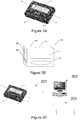
- FIG 3A illustrates an alternative embodiment where a cardiac monitoring system 100 is comprised of a smart phone 301 (the cardiac monitor of the illustrated system of Figure 3 A) as well as a retractable multi-use cardiac monitor 110.
- the smart phone 301 may include a processor and a memory (not illustrated as they are within the smart phone 301).
- the smart phone 301 also includes a display screen 305.
- the retractable multi-use cardiac monitor 110 transmits collected ECG data to the smart phone 301.
- the retractable multi-use cardiac monitor 110 stores the collected ECG data in a memory of the retractable multi-use cardiac monitor 110 prior to transmission.
- the smart phone 301 may operate as a Holter monitor, or may operate as an event monitor.
- the smart phone 301 may operate as a mobile cardiac telemetry monitor. In some embodiments, the smart phone 301 may operate as both a Holter monitor and an event monitor.
- the retractable multi-use cardiac monitor 110 wirelessly transmits collected ECG data to the smart phone 301 by a wireless radio.
- the wireless communication between the retractable multi-use cardiac monitor 110 and the smart phone 301 may be accomplished using any one of a variety of different wireless technologies including but not limited to 900Mhz radio, Bluetooth, IEEE 802.11 (Wi-Fi), WLAN, Personal Area Network, TransferJet, Ultra-wideband (UWB), IrDA, RFID, Wireless USB, Near Field Communication, or ZigBee.
- the communication between the retractable multi-use cardiac monitor 110 and the smart phone 301 may be wired.
- the retractable multi-use cardiac monitor 110 is powered by a battery, while in other embodiments the retractable multi-use cardiac monitor 110 is powered by a wired connection to smart phone 301.
- the retractable multi-use cardiac monitor 110 may include a processor and a memory.
- the processor may be a microcontroller or a microprocessor.
- the memory may be a RAM, EEPROM, FLASH, or any other suitable volatile or non-volatile storage medium or device.
- the retractable multi-use cardiac monitor 110 collects other biological data, such as temperature, and provides such data to smart phone 301 by a wireless radio or through a wired connection as discussed above which may be further transmitted as discussed in reference to Figure 3B or viewed by a health care professional as discussed below.
- the smart phone 301 may be configured to transmit data to a monitoring center, as provided by a health professional, a clinic, or a hospital.
- input received from the retractable multi-use cardiac monitor 110 is retained by the smart phone 301 and displayed on the smart phone 301 at a later time or used at a later time.
- the input received from the retractable multi-use cardiac monitor 110 may later be shown to a doctor or other health professional during a patient visit on the display screen 305 of the smart phone 301.
- the smart phone 301 both transmits collected data to a monitoring center and retains collected data for later display or use.
- Figure 3B illustrates various communication schemes for the smart phone 301.
- the smart phone 301 may transmit data collected from the retractable multi-use cardiac monitor 110 to a monitoring center, as provided by a health professional, a clinic, or a hospital by communicating with a cellular tower 302 of a cellular network.
- the smart phone 301 may transmit data to a monitoring center by communicating with a computer 303 that includes an application which stores and forwards the data to the monitoring center through the Internet (e.g. by email).
- the application on computer 303 may also be configured to allow a user of the smart phone 301 to print reports of the ECG data collected by the smart phone 301.
- Communication with the computer 302 may be wired or wireless.
- the smart phone 301 may plug into the computer using a USB or firewire cable.
- the smart phone 301 may communicate with the computer 303 through a variety of different wireless technologies including but not limited to 900Mhz radio, Bluetooth, IEEE 802.11 (Wi-Fi), WLAN, Personal Area Network, TransferJet, Ultra-wideband (UWB), IrDA, RFID, Wireless USB, Near Field Communication, or ZigBee.
- the smart phone 301 simply transmits collected data to a wireless router 304 which then transmits the data to the monitoring center through the Internet.
- the wireless router 304 may support any number of wireless technologies including but not limited to IEEE 802.11 (Wi-Fi).
- the smart phone 301 is configured to detect the presence of the wireless router 304, and when the presence of the wireless router 304 is detected, the smart phone 301 opportunistically transmits collected data to the wireless router 304 which then transmits the data to the monitoring center.
- the smart phone 301 is configured to transmit data to a monitoring center over a telephone connection by audio modulation.
- the smart phone 301 transmits collected data to the monitoring center through any number of intermediaries and through any number of communication technologies.
- the retractable multi-use cardiac monitor 110 may store collected data on an on-board memory and "push" the data to a cardiac monitor (e.g. base unit 105 of Figure 1 or smart phone 301 of Figure 3 A) .
- the retractable multi-use cardiac monitor 110 may store collected data on an on-board memory and is designed to await a request from a cardiac monitor (e.g. base unit 105 of Figure 1 or smart phone 301 of Figure 3 A) to "pull" data from the retractable multi-use cardiac monitor 110.
- the retractable multi-use cardiac monitor 110 may be configured to stream data as it is collected directly to a cardiac monitor (e.g. base unit 105 of Figure 1 or smart phone 301 of Figure 3A ).
- FIG. 3C illustrates an embodiment where the multi-use cardiac monitor 110 itself comprises the entire cardiac monitoring system 100.
- the multi-use cardiac monitor 110 may operate as a Holter monitor, or may operate as an event monitor. In an alternative embodiment the multi-use cardiac monitor 110 may operate as a mobile cardiac telemetry monitor. In some embodiments, the multi-use cardiac monitor 110 may operate as both a Holter monitor and an event monitor.
- the multi-use cardiac monitor 110 is configured to transmit collected ECG data to a monitoring center, as provided by a health professional, a clinic, or a hospital.
- the retractable multi-use cardiac monitor 110 stores the collected ECG data in a memory of the retractable multi-use cardiac monitor 110 prior to transmission.
- the retractable multi-use cardiac monitor 110 includes a display screen and the retractable multi-use cardiac monitor 110 retains any collected ECG data and displays the collected ECG data at a later time.
- the collected ECG data may later be shown to a doctor or other health professional during a patient visit on a display screen (e.g., 2101 or Figure 21 or 2201 of Figure 22 ) of the retractable multi-use cardiac monitor 110.
- the retractable multi-use cardiac monitor 110 both transmits collected ECG data to a monitoring center and retains collected ECG data for later display.
- the retractable multi-use cardiac monitor 110 may include a processor and a memory.
- the processor may be a microcontroller or a microprocessor.
- the memory may be a RAM, EEPROM, FLASH, or any other suitable volatile or non-volatile storage medium or device.
- the retractable multi-use cardiac monitor 110 collects other biological data, such as temperature, and transmits such data as discussed above and below, and may retain the data for later display or use.
- Figure 3C also illustrates various communication schemes for the retractable multi-use cardiac monitor 110 where it comprises the entire cardiac monitor system 100.
- the retractable multi-use cardiac monitor 110 may transmit collected data to a monitoring center, as provided by a health professional, a clinic, or a hospital by communicating with a cellular tower 302 of a cellular network by a wireless radio.
- the retractable multi-use cardiac monitor 110 may transmit data to a monitoring center by communicating with a computer 303 that includes an application which stores and forwards the data to the monitoring center through the Internet (e.g. by email).
- the application on computer 303 may also be configured to allow a user of the retractable multi-use cardiac monitor 110 to print reports of the data collected by the retractable multi-use cardiac monitor 110.
- Communication with the computer 302 may be wired or wireless by a wireless radio.
- the retractable multi-use cardiac monitor 110 may plug into the computer using a USB or firewire cable.
- the retractable multi-use cardiac monitor 110 may communicate with the computer 303 through a variety of different wireless technologies including but not limited to 900Mhz radio, Bluetooth, IEEE 802.11 (Wi-Fi), WLAN, Personal Area Network, TransferJet, Ultra-wideband (UWB), IrDA, RFID, Wireless USB, Near Field Communication, or ZigBee.
- the retractable multi-use cardiac monitor 110 by a wireless radio simply transmits collected data to a wireless router 304 which then transmits the data to the monitoring center through the Internet.
- the wireless router 304 may support any number of wireless technologies including but not limited to IEEE 802.11 (Wi-Fi).
- the retractable multi-use cardiac monitor 110 is configured to detect the presence of the wireless router 304, and when the presence of the wireless router 304 is detected, the retractable multi-use cardiac monitor 110 opportunistically transmits collected data by a wireless radio to the wireless router 304 which then transmits the data to the monitoring center.
- the retractable multi-use cardiac monitor 110 is configured to transmit data to a monitoring center over a telephone connection by audio modulation.
- the retractable multi-use cardiac monitor 110 transmits collected data to the monitoring center through any number of intermediaries and through any number of communication technologies.
- Figure 4 is a top-down view of a retractable multi-use cardiac monitor 110, according to one embodiment.
- the retractable multi-use cardiac monitor 110 includes left 401 and right sides 402 each comprised of a left and right side housing (also referenced as 401 and 402 respectively).
- the retractable multi-use cardiac monitor 110 may be comprised of any one of a number of different materials, including but not limited to plastic and metal.
- the illustrated embodiment of Figure 1 includes a symptom button 403 on the right 402 side of the retractable multi-use cardiac monitor 110.
- the symptom button 403 may be used by the patient to "wake up" the cardiac monitor with which the retractable multi-use cardiac monitor 110 is associated, such that the cardiac monitor may begin recording data as either a Holter or event or MCT monitor depending on the cardiac monitor's configuration.
- the symptom button 403 is used to indicate that a cardiac "event" has occurred, and the retractable multi-use cardiac monitor 110 may begin to record data relative to the "event.”
- the symptom button 403 may be used as an input to the retractable multi-use cardiac monitor 110, a cardiac monitor with which the retractable multi-use cardiac monitor 110 is associated, or any other portion of a system with which the retractable multi-use cardiac monitor 110 is associated.
- the symptom button 403 may be disposed on the left 401 side of the retractable multi-use cardiac monitor 110.
- the embodiment of Figure 4 also illustrates each of a processor 404, a memory 405, and a wireless radio 406.
- processor 404, a memory 405, and a wireless radio 406 are illustrated with dashed lines because they lie below the outer surface of the right side housing 402 and within the right side housing 402.
- processor 404, memory 405, and wireless radio 406 may be placed in various locations within the retractable multi-use cardiac monitor 110.
- processor 404 could be included in the left side housing 401.
- each of the processor 404, memory 405, and wireless radio 406 may be of various types in various embodiments.
- Figure 5 is also a top-down view of a retractable multi-use cardiac monitor 110, according to one embodiment.
- the embodiment of Figure 5 illustrates a retractable wire 501 that connects the left 401 and right 402 sides of the retractable multi-use cardiac monitor 110.
- the wire 501 may be fiber-optic or electrical. Further, the wire 501 may be shielded or non-shielded. In one embodiment, the wire 501 retracts into the right side 402. In another embodiment, the wire 501 retracts into the left side 401. In both embodiments, the left 401 and right 402 sides of retractable multi-use cardiac monitor 110 may be extended away from and toward one another.
- the retractable nature of the retractable multi-use cardiac monitor 110 allows for easy and convenient storage of the wire 501.
- Figure 6 is yet another illustration of an embodiment of a retractable multi-use cardiac monitor 110.
- the illustrated embodiment includes left 401 and right 402 sides, as well as a retractable wire 501.
- the illustrated embodiment also includes a symptom button 403 on the right side 402 of the retractable multi-use cardiac monitor 110.
- FIG. 7 is a top-down view of a wearable electrode 700, according to one embodiment.
- the wearable electrode 700 is comprised of an electrode contact 702 that is configured to contact skin.
- the wearable electrode 700 can detect electrical signals from a patient's heart through the electrode contact 702.
- the wearable electrode 700 also includes a top surface 703, as well as a bottom surface 701 that may include adhesive to facilitate connection of the wearable electrode 700 to the skin.
- the wearable electrode 700 also includes a connector 704 to allow the wearable electrode to be connected to a device.
- the connector 704 is illustrated as a metal post.
- the bottom surface 701 is also coated with a gel that improves electrical conduction between the patient's skin and the electrode contact 702.
- Figure 8 is a top-down view of a retractable multi-use cardiac monitor 110 with wearable electrodes (left 801 and right 802) attached, according to one embodiment.
- Figure 9 is a bottom-up view of a retractable multi-use cardiac monitor 110 with wearable electrodes (left 801 and right 802) attached, according to one embodiment.
- the left wearable electrode 801 includes a left electrode contact 901 and the right wearable electrode 802 includes a right electrode contact 902.
- the left 801 and right 802 wearable electrodes connect to the left 401 and right 402 sides of the retractable multi-use cardiac monitor 110 by connection to the left 903 and right 904 sensing connectors.
- Figure 7 illustrates a connector 704 for a wearable electrode 700.
- the sensing connectors (903 and 904) may be configured to accept the connector post 704 for connection to a wearable electrode.
- these wearable electrodes may be configured to contact the skin of a patient to detect electrical signals of the patient's heart through the electrode contacts.
- the wearable electrodes (left 801 and right 802) and consequently the electrode contacts (left 901 and right 902) are designed to be temporarily placed against the patient's skin by the patient to detect a small amount of ECG data.
- a patient may not be feeling well, and may desire to make a short recording of ECG data by holding the wearable electrodes (left 801 and right 802) of the retractable multi-use cardiac monitor 110 against their skin for short period.
- the wearable electrodes (left 801 and right 802) and consequently the electrode contacts (left 901 and right 902) are designed to be attached for an extended period of time.
- an adhesive is provided for wearable electrodes, which facilitates the attachment of the left 801 and right 802 wearable electrodes for an extended period of time.
- the left 401 and right 402 sides of the retractable multi-use cardiac monitor 110 are shown as dashed lines in this bottom-up view because they are disposed behind the left 801 and right 802 wearable electrodes.
- the left 903 and right 904 sensing connectors are shown as dashed lines in this bottom-up view because they are disposed behind the left 801 and right 802 wearable electrodes.
- the left 903 and right 904 sensing connectors, or the combination of the left 801 and right 802 wearable electrodes with the left 903 and right 904 sensing connectors collect ECG and other biological data.
- Figure 10 is a top-down view of a retractable multi-use cardiac monitor with wearable electrodes (left 801 and right 802) attached.
- the Figure 10 embodiment illustrates that the wire 501 may be flexible, and may move flexibly in any direction.
- Figure 10 illustrates the left 901 and right 902 electrode contacts as dashed lines in this top-down view because they are disposed behind the left 401 and right 402 sides, as well as the left 801 and right 802 wearable electrodes, respectively.
- Figure 11 is a side-view of a retractable multi-use cardiac monitor 110, according to one embodiment.
- Figure 11 illustrates left 903 and right 904 sensing connectors which protrude away from the left 401 and right 402 sides of the retractable multi-use cardiac monitor 110.
- Figure 12 is a side-view of a retractable multi-use cardiac monitor 110, according to one embodiment.
- Figure 12 illustrates the extractable wire 501 that connects the left 401 and right 402 sides of the retractable multi-use cardiac monitor 110.
- Figure 13 is a side-view of a retractable multi-use cardiac monitor 110 with wearable electrodes (left 801 and right 802) attached, according to one embodiment.
- Figure 13 similarly illustrates the extractable wire 501 that connects the left 401 and right 402 sides of the retractable multi-use cardiac monitor 110.
- Figure 13 also illustrates an embodiment in which the sensing connectors 903 and 904 are configured to accept a connector post 704 for wearable electrodes 801 and 802.
- Figure 14A is an illustration of a retractable multi-use cardiac monitor 110 attached to a cardiac monitoring patient 1401, according to one embodiment.
- the multi-use cardiac monitor 110 is configured to collect ECG signals through the left 801 and right 802 wearable electrodes that are connected to the patient's 1401 skin.
- Figure 14A illustrates a distance 1402 between the left 401 and right 402 sides of the retractable multi-use cardiac monitor 110.
- the retractable multi-use cardiac monitor 110 is configured to allow the left 401 and right 402 sides to be extended away from and toward one another.
- the retractable nature of the wire 501 also allows for easy storage of the wire 501.
- the retractable wire 501 allows the distance 1402 between the left 401 and right 402 sides of the retractable multi-use cardiac monitor 110 to be variable.
- the variable nature of the distance 1402 between the left 401 and right 402 sides allows a user of the retractable multi-use cardiac monitor 110 to adjust the distance between the left 801 and right 802 wearable contact electrodes that are connected to the patient's 1401 skin and are used to collect ECG signals.
- the variable nature of the distance 1402 allows a user to adjust the vector length between the corresponding left 903 and right 904 sensing connectors to which the left 801 and right 802 wearable contact electrodes are attached.
- the distance 1402 can be adjusted by the patient 1401 to achieve an optimum electrode vector length between the left 903 and right 904 sensing connectors for ECG signal collection.
- the retractable multi-use cardiac monitor 110 alone or in combination with another cardiac monitor is configured to assist the patient 1401 with the determination of an optimum electrode vector length.
- Interelectrode distance significantly affects the strength and fidelity of detected ECG signals.
- Various studies have been conducted that analyze the effect of interelectrode distance (vector length) on collected ECG signals. M. Puurtinen, et al., "Estimation of ECG Signal of closely separated bipolar electrodes using thorax models," Proceedings of the 26th Annual International Conference of the IEEE EMBS pp. 801-804, San Francisco, CA, USA, September 1-5, 2004 which is herein incorporated by reference in its entirety.
- FIG 14B is a flowchart illustrating the determination of an optimum electrode vector length, according to one embodiment.
- the Figure 14B flowchart illustrates the steps of optimum electrode vector length determination from the perspective of a cardiac monitor (e.g. base unit 105 of Figure 1 or smart phone of Figure 3 A) , in an embodiment where a retractable multi-use cardiac monitor 110 is used with another cardiac monitor to determine the optimum electrode vector length between the left 903 and right 904 sensing connectors.
- a cardiac monitor e.g. base unit 105 of Figure 1 or smart phone of Figure 3 A
- data is received by the cardiac monitor (e.g.
- step 1403 ECG data collected by the retractable multi-use cardiac monitor 110 at the current distance between the left 401 and right 402 sides is received by the cardiac monitor (e.g. base unit 105 of Figure 1 or smart phone of Figure 3A ).
- step 1404 the received ECG collected data and the data representing the distance between the left 401 and right 402 sides are recorded by the cardiac monitor (e.g. base unit 105 of Figure 1 or smart phone of Figure 3 A) .
- Steps 1402 through 1404 are repeated a number of times N with various distances between the left 401 and right 402 sides of the retractable multi-use cardiac monitor 110.
- the number of times N is variable.
- the number of times N is constant.
- the number of times N is variable and depends on intermediate calculations performed from the collected ECG data and distance values.
- an optimum electrode vector length between the left 903 and right 904 sensing connectors is calculated based on the ECG and distance data recorded in step 1404 by the processor of the cardiac monitor (e.g.
- a notification is generated indicating the optimum electrode vector length has been found.
- the notification may be generated by the cardiac monitor (e.g. base unit 105 of Figure 1 or smart phone of Figure 3 A) or the retractable multi-use cardiac monitor 110.
- the notification is an audible noise.
- the notification is visual such as by a light or a display on a visual display (e.g. 2101 of Figure 21 or 2201 of Figure 22 ) of the retractable multi-use cardiac monitor 110, or by a light or a visual display on the display of a cardiac monitor (e.g. on a display 175 of base unit 105 of Figure 1 or a display 305 of smart phone 301 of Figure 3 A) .
- an optimum electrode vector length is calculated based on comparison of recorded signal strengths of ECG data at various vector distances collected by Steps 1402 through 1404. In another embodiment, an optimum electrode vector length is calculated based on comparison of recorded signal fidelities of ECG data at various vector distances collected by Steps 1402 through 1404. In another embodiment, an optimum electrode vector length is calculated based on comparison of both recorded signal strengths as well as recorded signal fidelities of ECG data at various vector distances collected by Steps 1402 through 1404. In yet other embodiments, an optimum electrode vector length is calculated based on analyzing the ECG data at various vector distances collected by Steps 1402 through 1404 to determine if the collected ECG data represents a high fidelity Q S ECG pattern. In yet other embodiments, other signal quality measures are used to calculate an optimum vector length. The intermediate calculations noted above in reference to Figure 14B may be any of these operations.
- Figure 14C is a flowchart illustrating the determination of an optimum electrode vector length, according to one embodiment.
- the Figure 14C flowchart illustrates the steps of optimum electrode vector length determination from the perspective of a retractable multi-use cardiac monitor 110 in an embodiment where the retractable multi-use cardiac monitor 110 determines the optimum vector electrode between the left 903 and right 904 sensing connectors by itself.
- the retractable multi-use cardiac monitor 110 determines a distance between the left 401 and right 402 sides (and consequently left 903 and right 904 sensing connectors) of the retractable multi-use cardiac monitor 110 and the retractable multi-use cardiac monitor 110 records the distance.
- the retractable multi-use cardiac monitor 110 collects and records ECG data.
- the ECG data and distance between the left 401 and right 402 sides may be recorded in a memory of the retractable multi-use cardiac monitor 110.
- Steps 1407 and 1408 are repeated a number of times N with various distances between the left 401 and right 402 sides.
- the number of times N is variable.
- the number of times N is constant.
- the number of times N is variable and depends on intermediate calculations performed from the collected ECG data and distance between the left 401 and right 402 sides.
- an optimum electrode vector length between the left 903 and right 904 sensing connectors is calculated based on the ECG data at various vector distances recorded in steps 1407 and 1408 by a processor of the retractable multi-use cardiac monitor 110.
- the retractable multi-use cardiac monitor 110 generates a notification indicating the optimum electrode vector length has been found.
- the notification is an audible noise.
- the notification is visual such as by a light or a display on a display screen (e.g. 2101 of Figure 21 or 2201 of Figure 22 ) of the retractable multi-use cardiac monitor 110.
- an optimum electrode vector length is calculated based on comparison of recorded signal strengths of ECG data at various vector distances collected by Steps 1407 and 1408. In another embodiment, an optimum electrode vector length is calculated based on comparison of recorded signal fidelities of ECG data at various vector distances collected by Steps 1407 and 1408. In another embodiment, an optimum electrode vector length is calculated based on comparison of both recorded signal strengths as well as recorded signal fidelities of ECG data at various vector distances collected by Steps 1407 and 1408. In yet other embodiments, an optimum electrode vector length is calculated based on analyzing the ECG data at various vector distances collected by Steps 1407 and 1408 to determine if the collected ECG data represents a high fidelity Q S ECG pattern. In yet other embodiments, other signal quality measures are used to calculate an optimum vector length. The intermediate calculations noted above in reference to Figure 14C may be any of these operations.
- Figure 14D is a flowchart illustrating the determination of an optimum electrode vector length, according to one embodiment.
- the Figure 14D flowchart illustrates the steps of optimum electrode vector length determination from the perspective of a patient or a healthcare professional.
- the retractable multi-use cardiac monitor 110 alone or in combination with another cardiac monitor is configured to assist the patient or healthcare professional with the determination of an optimum electrode vector length as explained in Figures 14B and 14C above.
- the patient or healthcare professional adjusts a distance between the left 401 and right 402 sides of the retractable multi-use cardiac monitor 110.
- the patient or healthcare professional holds the retractable multi-use cardiac monitor 110 against a portion of a patient body to record data.
- Steps 1411 and 1412 are repeated a number of times N with various distances between the left 401 and right 402 sides.
- the number of times N is variable.
- the number of times N is constant.
- the number of times N is variable and depends on intermediate calculations performed from the collected data and distance adjustments.
- the patient or healthcare professional receives a notification of the optimum electrode vector length from either a cardiac monitor (e.g. base unit 105 of Figure 1 or smart phone 301 of Figure 3 A) or from the retractable multi-use cardiac monitor 110, as explained above in the discussion of Figures 14B and 14C .
- the patient or healthcare professional does not receive a notification in step 1413.
- the patient or healthcare professional reviews the iteratively collected ECG data at various vector distances to determine the optimum vector length.
- the patient or healthcare professional could review such data on a display screen (e.g. 2101 of Figure 21 or 2201 of Figure 22 ) of the retractable multi-use cardiac monitor 110, or on a display screen of a cardiac monitor (e.g. display 175 of base unit 105 of Figure 1 or display 305 of smart phone 301 of Figure 3 A) .
- FIG. 14E is a flowchart illustrating the collection of and transmission of data, according to one embodiment.
- the retractable multi-use cardiac monitor 110 collects ECG or other biological data as described above.
- ECG or biological data may be collected from more than two electrodes or sensing connectors as described, for example, in reference to Figures 17, 19 , and 20 below.
- the collected data is stored. The collected data may be stored in a memory of the retractable multi-use cardiac monitor 110. The collected data is then transmitted as described in the various embodiments above to a destination.
- Figure 15 is an illustration of a finger electrode configuration of the retractable multi-use cardiac monitor 110, according to one embodiment.
- a user of the retractable multi-use cardiac monitor 110 is placing a left side finger 1501 and a right side finger 1502 onto the left 903 and right 904 sensing connectors respectively.
- the left 1501 and right 1502 fingers are from different hands.
- the retractable multi-use cardiac monitor 110 as illustrated in Figure 15 may collect ECG data from a patient when that patient applies the left 1501 and right 1502 side fingers onto the left 903 and right 904 sensing connectors, respectively.
- Figure 16 is also an illustration of a finger electrode configuration of the retractable multi-use cardiac monitor 110 with the wire 501 retracted.
- the Figure 16 embodiment illustrates a left 1501 and right 1502 finger attached to the left 903 and right 904 sensing connectors respectively.
- the left 903 and right 904 sensing connectors may be contacted to any body part of a patient to collect ECG data.
- left 903 and right 904 sensing connectors can be contacted to the chest, the legs, ankles, wrists or the arms of a patient.
- the left 903 and right 904 sensing connectors may be designed with different shapes or sizes.
- the left 903 and right 904 sensing connectors are shaped to receive a finger.
- a patient may not be feeling well, and may desire to make a short recording of ECG data without attaching wearable electrodes by merely holding the left 903 and right 904 sensing connectors against their chest for a short period.
- a patient may desire to temporarily hold the left 903 and right 904 sensing connectors against their chest by moving the left 401 and right 402 sides of the retractable multi-use cardiac monitor 110 away from one another to create an optimum vector length as illustrated in Figure 14A .
- Figure 17 is a top-down view of a retractable multi-use cardiac monitor 110 that includes a second retractable wire 1703, according to another embodiment.
- the retractable multi-use cardiac monitor 110 includes a second wire 1703 connected to a third portion 1701 of the retractable multi-use cardiac monitor 110.
- the third portion 1701 is also attached to a third 1702 wearable electrode and is comprised of a third housing (also referenced as 1701).
- the third wearable electrode 1702 may be connected to a patient's skin along with the left 801 and right 802 side wearable electrodes, thereby providing an increased number of electrode contacts on the patient's skin and increasing the quality of the collected ECG signal.
- the third wearable electrode 1702 is used as a ground.
- the second wire 1703 retracts into the right side 402. In an alternative embodiment, the second wire 1703 retracts into the third portion 1701. In one embodiment, the second wire 1703 is detachable from the third portion 1701. In an alternative embodiment, the second wire 1703 simply plugs into a portion of the right side 402. In further embodiments, there may be an unlimited number of retractable or connectable wires which may retract or connect to either the left 401 or right sides 402 for use in the collection of electrical signals from a patient's heart, for reference wires, or electrical grounds.
- Figure 17 also illustrates a simple wire 1704 that is connected to the top of the right 402 side of the retractable multi-use cardiac monitor 110. Wire 1704 may be a ground or a signal wire.
- Figure 17 also illustrates a symptom button 1705.
- the symptom button 1705 may operate as described above with respect to Figure 4 . Additionally, the symptom button may be used when a patient desires to collect a short amount of data by temporarily placing the retractable multi-use cardiac monitor 110 against the patient's body, or if the patient desires to collect data using the sensing connectors 903 and 904 as finger electrodes as discussed in Figures 15 and 16 . In such an embodiment, only two of the left 401 and right 402 sides or the third portion 1701 should be active for the collection of ECG data. In such an embodiment, the symptom button 1705 or a dip switch or other means may be used to indicate to the monitor that only 2 of 3 electrodes will be used.
- the symptom button 1705 or a dip switch or other means could be used to disable the right 402 side, leaving only the left side 401 and the third portion 1701 active for the collection of ECG data during temporary placement of the retractable multi-use cardiac monitor 110 against a portion of a patient body.
- the non-designation of the right side 402 during data collection eliminates any electrical noise that may be provided by the right side 402 during collection and allows for electrical isolation of the left side 401 and right portion 1701 relative to one another.
- Figure 18 is a side-view of a retractable multi-use cardiac monitor, according to one embodiment.
- Figure 18 illustrates an embodiment where the wire 501 retracts into the right 402 side of the retractable multi-use cardiac monitor 110 using a single wire retraction barrel 1801 as a wire retractor.
- the wire 501 may retract into the left 401 side of the retractable multi-use cardiac monitor 110, and in such an embodiment the left 401 side would include a single wire retraction barrel as a wire retractor.
- Figure 19 is also a side-view of a retractable multi-use cardiac monitor, according to one embodiment.
- the embodiment illustrated in Figure 19 includes left 401 and right 402 sides as well as a third portion 1701.
- the illustrated embodiment also includes a wire 501 and a second wire 1703.
- the wire 501 and second wire 1703 retract into the right side 402 by a first 1902 and second 1903 retraction barrel respectively as wire retractors.
- the Figure 19 embodiment also illustrates a third sensing connector 1901.
- Figure 20 is a further illustration of a side-view of a retractable multi-use cardiac monitor 110, according to one embodiment.
- the first retraction barrel 1902 is within the left side 401 and the second retraction barrel 1903 is within the third portion 1701.
- the wire 501 retracts into the left side 401 by the first retraction barrel 1902
- the second wire 1703 retracts into the third portion 1701 by the second retraction barrel 1903.
- Figure 21 is yet another illustration of an embodiment of a retractable multi-use cardiac monitor 110.
- the illustrated embodiment includes left 401 and right 402 sides.
- the illustrated embodiment also includes a display screen 2101 which is configured to display captured ECG or other biological data.
- Figure 22 similarly illustrates an embodiment of a retractable multi-use cardiac monitor 110, where a display screen 2201 is provided on the right side 402 in conjunction with the symptom button 403.
- Figure 23A is a flowchart illustrating the determination of an optimum set of electrode vector lengths, according to one embodiment.
- the embodiment of Figure 23A is directed to the determination of an optimum set of electrode vector lengths with an embodiment of the retractable multi-use cardiac monitor 110 that includes both left 401 and right sides 402, as well as a third portion 14071 as illustrated, for example, in Figures 17, 19 , and 20 and discussed above.
- the Figure 23A flowchart illustrates the steps of optimum electrode vector length determination from the perspective of a cardiac monitor (e.g.
- step 2301 data is received by the cardiac monitor (e.g.
- the retractable multi-use cardiac monitor 110 representing a distance between the left 401 and right 402 sides of the retractable multi-use cardiac monitor 110 (and consequently left 903 and right 904 sensing connectors), as well as data representing a distance between the right side 402 and the third portion 1701 of the retractable multi-use cardiac monitor 110 (and consequently the right sensing connector 904 and the third sensing connector 1901).
- a determination may be made by not sensing any such movement.
- ECG data collected by the retractable multi-use cardiac monitor 110 at the current distances between the left side 401, right side 402, and third portion 1701, respectively, is received by the cardiac monitor (e.g. base unit 105 of Figure 1 or smart phone of Figure 3A ).
- the received ECG collected data and the data representing the distance between the left 401 and right 402 sides, and the distance between the right side 402 and the third portion 1701 are recorded by the cardiac monitor (e.g. base unit 105 of Figure 1 or smart phone of Figure 3 A) .
- the received ECG collected data and the data representing the distances between the left side 401, right side 402, and third portion 1701, respectively, may be recoded in a memory.
- Steps 2301 through 2303 are repeated a number of times N with various distances between the left side 401, right side 402, and third portion 1701, respectively of the retractable multi-use cardiac monitor 110.
- the number of times N is variable.
- the number of times N is constant.
- the number of times N is variable and depends on intermediate calculations performed from the collected ECG data and distance values.
- a set of optimum electrode vector lengths between the left side 401, right side 402, and third portion 1701, respectively, is calculated based on the ECG and distance data recorded in Step 2303 by the processor of the cardiac monitor (e.g. by the processor of base unit 105 of Figure 1 or the processor of smart phone 301 of Figure 3 A) .
- a notification is generated indicating the optimum set of electrode vector lengths has been found.
- the notification may be generated by the cardiac monitor (e.g. base unit 105 of Figure 1 or smart phone of Figure 3 A) or the retractable multi-use cardiac monitor 110.
- the notification is an audible noise.
- the notification is visual such as by a light or a display on a visual display (e.g. 2101 of Figure 21 or 2201 of Figure 22 ) of the retractable multi-use cardiac monitor 110, or by a light or a visual display on the display of a cardiac monitor (e.g. on a display 175 of base unit 105 of Figure 1 or a display 305 of smart phone 301 of Figure 3A ).
- a set of optimum vector lengths is calculated based on comparison of recorded signal strengths of ECG data at various vector distances collected by Steps 2301 through 2303. In another embodiment, a set of optimum vector lengths is calculated based on comparison of recorded signal fidelities of ECG data at various vector distances collected by Steps 2301 through 2303. In another embodiment, a set of optimum vector lengths is calculated based on comparison of both recorded signal strengths as well as recorded signal fidelities of ECG data at various vector distances collected by Steps 2301 through 2303.
- a set of optimum vector lengths is calculated based on analyzing the ECG data at various vector distances collected by Steps 2301 through 2303 to determine if the collected ECG data represents a high fidelity Q S ECG pattern.
- other signal quality measures are used to calculate an optimum vector lengths. The intermediate calculations noted above in reference to Figure 23A may be any of these operations.
- Figure 23B is a flowchart illustrating the determination of an optimum set of electrode vector lengths, according to one embodiment.
- the Figure 23B flowchart illustrates the steps of optimum electrode vector length determination from the perspective of a retractable multi-use cardiac monitor 110 in an embodiment where the retractable multi-use cardiac monitor 110 determines an optimum set of electrode vector lengths by itself. Further, the Figure 23B flowchart is directed to the determination of an optimum set of electrode vector lengths in an embodiment of the retractable multi-use cardiac monitor 110 that includes both left 401 and right sides 402, as well as a third portion 1701 as illustrated, for example, in Figures 17, 19 , and 20 and discussed above.
- the retractable multi-use cardiac monitor 110 determines a distance between the left 401 and right 402 sides of the retractable multi-use cardiac monitor 110 (and consequently left 903 and right 904 sensing connectors), and distance between the right side 402 and the third portion 1701 of the retractable multi-use cardiac monitor 110 (and consequently the right sensing connector 904 and the third sensing connector 1901). In some embodiments, if any of the left 401, right 402, or third portion 1701 have not moved since a previous iteration, a determination may be made by not sensing any such movement. Data representing each of the distances is recorded.
- the retractable multi-use cardiac monitor 110 collects and records ECG data using each of the left 903, right 904, and third 1901 sensing connectors.
- the ECG data collected and the distances between the left side 401, right side 402, and third portion 1701, respectively, may be recorded in a memory of the retractable multi-use cardiac monitor 110.
- Steps 2306 and 2307 are repeated a number of times N with various distances between the left side 401, right side 402, and third portion 1701, respectively.
- the number of times N is variable. In other embodiments, the number of times N is constant.
- the number of times N is variable and depends on intermediate calculations performed from the collected ECG data and distances between the left side 401, right side 402, and third portion 1701, respectively.
- a set of optimum electrode vector lengths between the left side 401, right side 402, and third portion 1701, respectively, is calculated based on the ECG and distance data collected in Steps 2306 and 2307 by a processor of the retractable multi-use cardiac monitor 110.
- a notification is generated indicating the optimum set of electrode vector lengths has been found.
- the notification is an audible noise.
- the notification is visual such as by a light or a display on a display screen (e.g. 2101 of Figure 21 or 2201 of Figure 22 ) of the retractable multi-use cardiac monitor 110.
- a set of optimum vector lengths is calculated based on comparison of recorded signal strengths of ECG data at various vector distances collected by Steps 2306 and 2307. In another embodiment, a set of optimum vector lengths is calculated based on comparison of recorded signal fidelities of ECG data at various vector distances collected by Steps 2306 and 2307. In another embodiment, a set of optimum vector lengths is calculated based on comparison of both recorded signal strengths as well as recorded signal fidelities of ECG data at various vector distances collected by Steps 2306 and 2307.
- a set of optimum vector lengths is calculated based on analyzing the ECG data at various vector distances collected by Steps 2306 and 2307 to determine if the collected ECG data represents a high fidelity Q S ECG pattern.
- other signal quality measures are used to calculate an optimum vector length. The intermediate calculations noted above in reference to Figure 23B may be any of these operations.
- Figure 23C is a flowchart illustrating the determination of a set of optimum electrode vector lengths, according to one embodiment.
- the Figure 23C flowchart illustrates the steps of optimum electrode vector length determination from the perspective of a patient or a healthcare professional.
- the retractable multi-use cardiac monitor 110 alone or in combination with another cardiac monitor is configured to assist the patient or healthcare professional with the determination of a set of optimum electrode vector lengths as explained in Figures 23A and 23B above.
- the embodiment of Figure 23 C is directed to the determination of an optimum set of electrode vector lengths with an embodiment of the retractable multi-use cardiac monitor 110 that includes both left 401 and right sides 402, as well as a third portion 14071 as illustrated, for example, in Figures 17, 19 , and 20 and discussed above.
- step 2310 the patient or healthcare professional adjusts at least one of a distance between the left 401 and right 402 sides of the retractable multi-use cardiac monitor 110, or a distance between the right side 402 and the third portion 1701.
- the patient or healthcare professional may adjust both distances.
- step 2311 the patient or healthcare professional holds or applies the retractable multi-use cardiac monitor 110 against a portion of a patient body to record data.
- Steps 2311 and 2312 are repeated a number of times N with various distances between the left side 401, right side 402, and third portion 1701, respectively. In some embodiments, the number of times N is variable. In other embodiments, the number of times N is constant.
- the number of times N is variable and depends on intermediate calculations performed from the collected data and distance adjustments.
- the patient or healthcare professional receives a notification indicating that the set of optimum electrode vector lengths has been found from either a cardiac monitor (e.g. base unit 105 of Figure 1 or smart phone 301 of Figure 3 A) or from the retractable multi-use cardiac monitor 110, as explained above in the discussion of Figures 23A and 23B .
- the patient or healthcare professional does not receive a notification in step 2312. Rather, the patient or healthcare professional reviews the iteratively collected ECG data at various vector distances to determine the set of optimum vector lengths. For example, the patient or healthcare professional could review such data on a display screen (e.g.
- a display screen of a cardiac monitor e.g. display 175 of base unit 105 of Figure 1 or display 305 of smart phone 301 of Figure 3 A.
Abstract
Methods are disclosed of determining an optimum electrode vector length between a first sensing connector of a first side of a retractable multi-use cardiac monitor and a second sensing connector of a second side of the retractable multi-use cardiac monitor. One method comprises receiving from the retractable multi-use cardiac monitor at a smart phone data representing a distance between the first sensing connector of the retractable multi-use cardiac data monitor and the second sensing connector of the retractable multi-use cardiac data monitor. Electrocardiogram (ECG) data is collected by the retractable multi-use cardiac data monitor through the first and second sensing connectors and recorded, along with the received data representing the distance between the first and second sensing connectors. These steps are then iteratively repeated. The processor of the smart phone is then used to calculate an optimum electrode vector length between the first sensing connector of the first side of the retractable multi-use cardiac monitor and the second sensing connector of the second side of the retractable multi-use cardiac monitor based on the ECG data collected and the data representing the distance between the first and second sensing connectors. A notification is then generated that the optimum electrode vector length has been found.
Description
- The present application claims the benefit of and priority to
U.S. Provisional Patent Application No. 61/347,117, filed May 21, 2010 - The present invention relates generally to the field of cardiac monitoring. Specifically, the present invention is directed towards a retractable multi-use cardiac monitor.
- The following description of the background of the invention is provided simply as an aid in the understanding of the invention and is not admitted to describe or constitute prior art to the invention.
- Cardiac monitoring systems are generally comprised of a series of electrodes attached to the chest area of a patient to collect ECG data. The series of electrodes are usually connected to a series of wires. However, the inventor has perceived that the series of electrodes and interconnected wires are not provided in a compact portable form that allows for easy adjustment of the vector length between the electrodes.
- Accordingly, the inventor has perceived that there is a need for a retractable multi-use cardiac monitor that is compact in form and allows for easy adjustment of the vector length between the electrodes of the retractable multi-use cardiac monitor.
- According to one embodiment, a retractable multi-use cardiac monitor is provided. The retractable multi-use cardiac monitor includes a memory, a first side comprising a first housing wherein a first sensing connector is on the outside of the first housing, and wherein the first sensing connector is configured to collect electrocardiogram (ECG) data and store ECG data onto the memory. The retractable multi-use cardiac monitor further includes a second side comprising a second housing including a wire retractor and a second sensing connector, wherein the second sensing connector is on the outside of the second housing, and the wire retractor is configured to extend and retract a wire that connects the second and first sides, and wherein the second sensing connector is configured to collect ECG data and store ECG data onto the memory, and a wireless radio configured to transmit a portion of collected ECG data from the memory to a destination
- According to another embodiment, a method of collecting electrocardiogram (ECG) data with a retractable multi-use cardiac monitor is provided, wherein the retractable multi-use cardiac monitor includes a memory, a first side that includes a first housing wherein a first sensing connector is on the outside of the first housing, a second side including a second housing and a second sensing connector, wherein the second sensing connector is on the outside of the second housing, and a wireless radio. The method includes collecting ECG data from the first and second sensing connectors of the retractable multi-use cardiac monitor, wherein the first and second sensing connectors are placed against the skin of a chest area of a human patient, recording the collected ECG data onto the memory of the retractable multi-use cardiac monitor, and transmitting a portion of the collected ECG data to a destination.
- According to yet another embodiment, a method of determining an optimum electrode vector length between a first sensing connector of a first side of a retractable multi-use cardiac monitor and a second sensing connector of a second side of the retractable multi-use cardiac monitor is provided. The method includes (A) receiving from the retractable multi-use cardiac monitor at a smart phone data representing a distance between the first sensing connector of the retractable multi-use cardiac data monitor and the second sensing connector of the retractable multi-use cardiac data monitor, wherein the smart phone includes a processor, (B) receiving electrocardiogram (ECG) data collected by the retractable multi-use cardiac data monitor through the first and second sensing connectors, (C) recording the ECG data collected in step B and the data representing the distance between the first and second sensing connectors received in step A, and (D) iteratively repeating steps A-C a number of times. The method further includes (E) calculating, by the processor of the smart phone, an optimum electrode vector length between the first sensing connector of the first side of the retractable multi-use cardiac monitor and the second sensing connector of the second side of the retractable multi-use cardiac monitor based on the ECG data collected in step B and the data representing the distance between the first and second sensing connectors received in step A, and (F) generating a notification of that the optimum electrode vector length has been found.
- According to yet another embodiment a method of determining an optimum electrode vector length between a first sensing connector of a first side of a retractable multi-use cardiac monitor and a second sensing connector of a second side of the retractable multi-use cardiac monitor is provided. The method includes (A) determining a distance between the first sensing connector of the retractable multi-use cardiac data monitor and the second sensing connector of the retractable multi-use cardiac data monitor, and recording data representing the distance, (B) collecting electrocardiogram (ECG) data through the first and second sensing connectors and recording the collected ECG data, and (C) iteratively repeating A-B a number of times. The method further includes (E) calculating, by a processor of the retractable multi-use cardiac monitor an optimum electrode vector length between the first sensing connector of the first side of the retractable multi-use cardiac monitor and the second sensing connector of the second side of the retractable multi-use cardiac monitor based on the ECG data collected in step B and the data representing the distance between the first and second sensing connectors recorded in step A, and (F) generating a notification of that the optimum electrode vector length has been found.
-
-
Figure 1 is an illustration of a cardiac monitor system, according to one embodiment. -
Figure 2A is an illustration of a cardiac monitor system, according to one embodiment. -
Figure 2B is an illustration of a cardiac monitor system, according to one embodiment. -
Figure 2C is an illustration of a cardiac monitor system, according to one embodiment. -
Figure 3A is an illustration of a cardiac monitor system, according to one embodiment. -
Figure 3B is an illustration of a cardiac monitor system, according to one embodiment. -
Figure 3C is an illustration of a cardiac monitor system, according to one embodiment. -
Figure 4 is a top-down view of a retractable multi-use cardiac monitor, according to one embodiment. -
Figure 5 is a top-down view of a retractable multi-use cardiac monitor, according to one embodiment. -
Figure 6 is a top-down view of a retractable multi-use cardiac monitor, according to one embodiment. -
Figure 7 is an illustration of a wearable electrode, according to one embodiment. -
Figure 8 is a top-down view of a retractable multi-use cardiac monitor with wearable electrodes attached, according to one embodiment. -
Figure 9 is a bottom-up view of a retractable multi-use cardiac monitor with wearable electrodes attached, according to one embodiment. -
Figure 10 is a top-down view of a retractable multi-use cardiac monitor with wearable electrodes attached, according to one embodiment. -
Figure 11 is a side-view of a retractable multi-use cardiac monitor, according to one embodiment. -
Figure 12 is a side-view of a retractable multi-use cardiac monitor, according to one embodiment. -
Figure 13 is a side-view of a retractable multi-use cardiac monitor with wearable electrodes attached, according to one embodiment. -
Figure 14A is an illustration of a retractable multi-use cardiac monitor attached to a cardiac monitoring patient, according to one embodiment. -
Figure 14B is a flowchart illustrating the determination of an optimum electrode vector length, according to one embodiment. -
Figure 14C is a flowchart illustrating the determination of an optimum electrode vector length, according to one embodiment. -
Figure 14D is a flowchart illustrating the determination of an optimum electrode vector length, according to one embodiment. -
Figure 14E is a flowchart illustrating the collection and transmission of data, according to one embodiment. -
Figure 15 is an illustration of a finger electrode configuration of a retractable multi-use cardiac monitor, according to one embodiment. -
Figure 16 is an illustration of a finger electrode configuration of a retractable multi-use cardiac monitor, according to one embodiment. -
Figure 17 is a top-down view of a retractable multi-use cardiac monitor that includes multiple additional wires, according to one embodiment. -
Figure 18 is a side-view of a retractable multi-use cardiac monitor, according to one embodiment. -
Figure 19 is a side-view of a retractable multi-use cardiac monitor, according to one embodiment. -
Figure 20 is a side-vide of a retractable multi-use cardiac monitor, according to one embodiment. -
Figure 21 is a top-down view of a retractable multi-use cardiac monitor, according to one embodiment. -
Figure 22 is a top-down view of a retractable multi-use cardiac monitor, according to one embodiment. -
Figure 23A is a flowchart illustrating the determination of a set of optimum electrode vector lengths, according to one embodiment. -
Figure 23B is a flowchart illustrating the determination of a set of optimum electrode vector lengths, according to one embodiment. -
Figure 23C is a flowchart illustrating the determination of a set of optimum electrode vector lengths, according to one embodiment. - Unless otherwise specified, "a" or "an" means "one or more."
- With regard to the present disclosure, terms such as "left", "right", and "portion" are used to identify parts of the disclosed retractable multi-use cardiac monitor and are not meant to be limiting, or to mean that such parts of the disclosed retractable multi-use cardiac monitor are in any particular position or orientation relative to the outside environment.
- It is to be understood that both the foregoing brief description of the drawings and the following detailed description are exemplary and explanatory only, and are not restrictive of the invention. These and other features, aspects and advantages of the present invention will become apparent from the following description, and the accompanying exemplary embodiments shown in the drawings, which are briefly described below.
- Applicant hereby incorporates by reference
U.S. Patent Publication No. 2008/0097231 ,U.S. App. Serial No. 11/550,759, Filed October 18, 2006 cardiac monitor 110 as herein described may be used as a wearable electrode system (110 ofU.S. Patent Publication No. 2008/0097231 ) within a cardiac event monitoring system (100 ofU.S. Patent Publication No. 2008/0097231 ). - Cardiac event monitoring is a procedure that is conducted on patients who report symptoms that may be cardiac in origin, and that occur infrequently, such as, for example, three times or less in one week. Cardiac monitoring is performed by the sensing and storage of electrocardiogram (ECG) data that characterizes activity of a patient's heart by a "cardiac monitor." In some instances, "event monitoring" is used to detect clinically significant heart related events. Event monitoring may be performed by patient activation, whereby the patient senses a cardiac event and causes data to be recorded. In other embodiments of event monitoring, a cardiac monitor analyzes incoming ECG data, identifies a clinically significant ECG event, and stores data related to the detected ECG event (e.g. an event monitor may identify particular types of Arrhythmias). In some embodiments, the cardiac monitor's ability to analyze incoming ECG data allows the cardiac monitor to detect a cardiac condition where a patient is otherwise asymptomatic. Another type of monitoring is "Holter" monitoring. Holter monitoring is directed to constant recording and storage of ECG data from a patient. The quality and amount of ECG data recorded and stored varies based on quality requirements and memory storage limitations. Another cardiac monitoring technology is mobile cardiac telemetry. Mobile cardiac telemetry cardiac monitors may be configured to perform various types of event monitoring as well as constant storage of ECG similar to a holter monitor. In some embodiments, mobile cardiac telemetry monitors operate using auto-push technology that is configured to automatically transmit collected data to a monitoring center. A patient generally carries a cardiac monitor during a testing period, which can last for several days or up to, for example, 30 days.
-
Figure 1 illustrates an example of a cardiac monitor system. Referring toFigure 1 , acardiac monitor system 100 includes a base unit 105 (the cardiac monitor of the illustrated system ofFigure 1 ), and a retractable multi-usecardiac monitor 110. The retractable multi-usecardiac monitor 110 may include a processor and a memory. The processor may be a microcontroller or a microprocessor. The memory may be a RAM, EEPROM, FLASH, or any other suitable volatile or non-volatile storage medium or device. Thebase unit 105 includes abase connector 120 and abody 107 that houses the electrical components and includes a user interface. The retractable multi-usecardiac monitor 110 collects ECG data from a patient and provides that data to thebase unit 105 through wireless communication by a wireless radio. In some embodiments, the retractable multi-usecardiac monitor 110 stores the collected ECG data in a memory of the retractable multi-usecardiac monitor 110 prior to transmission. The wireless communication between the retractable multi-usecardiac monitor 110 and thebase unit 105 may be accomplished using any one of a variety of different wireless technologies including but not limited to 900Mhz radio, Bluetooth, IEEE 802.11 (Wi-Fi), WLAN, Personal Area Network, TransferJet, Ultra-wideband (UWB), IrDA, RFID, Wireless USB, Near Field Communication, or ZigBee. In an alternative embodiment, the communication between the retractable multi-usecardiac monitor 110 and thebase unit 105 may be wired. Further, in some embodiments the retractable multi-usecardiac monitor 110 is powered by a battery, while in other embodiments the retractable multi-usecardiac monitor 110 is powered by a wired connection tobase unit 105. In yet further embodiments, the retractable multi-usecardiac monitor 110 collects other biological data, such as temperature, and provides such data tobase unit 105 by a wireless radio or through a wired connection as discussed above which may be further transmitted as discussed in reference toFigure 2C or viewed by a health care professional as discussed below. - Referring now to
Figures 1 ,2A and 2B , thebase unit 105 is pager-sized, and is either handheld or patient- worn. Thebase unit 105 includes thebody 107 that houses components that control operation of thecardiac monitor system 100. Thus, thebase unit 105 includes acontroller 150 within thebody 107, and various input and output devices coupled to thecontroller 150 through thebody 107. Thecontroller 150 receives power from apower source 155 that may be provided by batteries that are placed within acompartment 200 on a side of thebody 107. Thebody 107 and thebattery compartment 200 can be made of a suitable non-conductive lightweight material, such as a rigid plastic. Thepower source 155 may be turned off and on by a switch 205 (Figures 1 and2B ) accessible on thecompartment 200 and connected to thepower source 155 and thecontroller 150. - The
controller 150 includes a processor 151, memory 152, aclock 153, and acounter 154 to process signals from the retractable multi-usecardiac monitor 110, receive input from a patient or a service technician using thesystem 100, and transmit recorded data to a monitoring center, as provided by a health professional, a clinic, or a hospital. In an alternative embodiment, input received from the retractable multi-usecardiac monitor 110 is retained by thebase unit 105 and displayed on thebase unit 105 at a later time. For example, the input received from the retractable multi-usecardiac monitor 110 may later be shown to a doctor or other health professional during a patient visit. In some embodiments, thebase unit 105 both transmits collected data to a monitoring center and retains collected data for later display or use. - The input devices on the
base unit 105 include asymptom record button 160, a yes/transmitbutton 165, and a nobutton 170. The yes/transmitbutton 165 can be used in one of two ways: it can be used as a response button to answer "yes" when queried by thecontroller 150, or it can be used to indicate to thecontroller 150 to transmit the ECG. The nobutton 170 can be used in one of two ways: it can be used as a response button to answer "no" when queried by thecontroller 150, it can be used to indicate to thecontroller 150 to cancel a transmission of an ECG. - The output devices on the
base unit 105 include adisplay 175 such as a liquid crystal display (LCD) that provides an interface with the patient and/or a technician, and aspeaker 180 for transmitting data regarding the recording. For example, thedisplay 175 may be used to show data collected from the retractable multi-usecardiac monitor 110 to a health care professional during a patient visit. - The
system 100 can be worn for days or weeks, as it is intended for use by patients who are experiencing symptoms that are transient and infrequent in nature. Thebase unit 105 can be worn outside the patient's clothing if there is any chance that moisture (for example, sweat) might come in contact with thebase unit 105. Thebase unit 105 can be worn under outer wear, such as raincoats or jackets, for protection during wet or cold conditions. In one embodiment, thebase unit 105 may operate as a Holter monitor, or may operate as an event monitor. In an alternative embodiment thebase unit 105 may operate as a mobile cardiac telemetry monitor. In some embodiments, thebase unit 105 may operate as both a Holter monitor and an event monitor. -
Figure 2C illustrates various communication schemes for thebase unit 105. In some embodiments, thebase unit 105 may transmit data to a monitoring center, as provided by a health professional, a clinic, or a hospital by communicating with acellular tower 201 of a cellular network. In an alternative embodiment, thebase unit 105 may transmit data to a monitoring center by communicating with acomputer 202 that includes an application which stores and forwards the data to the monitoring center through the Internet (e.g. by email). The application oncomputer 202 may also be configured to allow a user of thebase unit 105 to print reports of the data collected by thebase unit 105. Communication with thecomputer 202 may be wired or wireless. For example, thebase unit 105 may plug into thecomputer 202 using a USB or firewire cable. In an alternative embodiment, thebase unit 105 may communicate with thecomputer 202 through a variety of different wireless technologies including but not limited to 900Mhz radio, Bluetooth, IEEE 802.11 (Wi-Fi), WLAN, Personal Area Network, TransferJet, Ultra-wideband (UWB), IrDA, RFID, Wireless USB, Near Field Communication, or ZigBee. In another embodiment, thebase unit 105 simply communicates with awireless router 203 which then communicates to the monitoring center through the Internet. Thewireless router 203 may support any number of wireless technologies including but not limited to IEEE 802.11 (Wi-Fi). In a related embodiment, thebase unit 105 is configured to detect the presence of thewireless router 203, and when the presence of thewireless router 203 is detected, thebase unit 105 opportunistically transmits collected data to thewireless router 203 which then transmits the data to the monitoring center. In yet another embodiment, thebase unit 105 is configured to transmit data to a monitoring center over a telephone connection by audio modulation through thespeaker 180. In yet further embodiments, thebase unit 105 transmits collected data to the monitoring center through any number of intermediaries and through any number of communication technologies. -
Figure 3A illustrates an alternative embodiment where acardiac monitoring system 100 is comprised of a smart phone 301 (the cardiac monitor of the illustrated system ofFigure 3 A) as well as a retractable multi-usecardiac monitor 110. Thesmart phone 301 may include a processor and a memory (not illustrated as they are within the smart phone 301). Thesmart phone 301 also includes adisplay screen 305. In the disclosed embodiment, the retractable multi-usecardiac monitor 110 transmits collected ECG data to thesmart phone 301. In some embodiments, the retractable multi-usecardiac monitor 110 stores the collected ECG data in a memory of the retractable multi-usecardiac monitor 110 prior to transmission. Thesmart phone 301 may operate as a Holter monitor, or may operate as an event monitor. In an alternative embodiment thesmart phone 301 may operate as a mobile cardiac telemetry monitor. In some embodiments, thesmart phone 301 may operate as both a Holter monitor and an event monitor. In one embodiment, the retractable multi-usecardiac monitor 110 wirelessly transmits collected ECG data to thesmart phone 301 by a wireless radio. The wireless communication between the retractable multi-usecardiac monitor 110 and thesmart phone 301 may be accomplished using any one of a variety of different wireless technologies including but not limited to 900Mhz radio, Bluetooth, IEEE 802.11 (Wi-Fi), WLAN, Personal Area Network, TransferJet, Ultra-wideband (UWB), IrDA, RFID, Wireless USB, Near Field Communication, or ZigBee. In an alternative embodiment, the communication between the retractable multi-usecardiac monitor 110 and thesmart phone 301 may be wired. Further, in some embodiments the retractable multi-usecardiac monitor 110 is powered by a battery, while in other embodiments the retractable multi-usecardiac monitor 110 is powered by a wired connection tosmart phone 301. As noted above, the retractable multi-usecardiac monitor 110 may include a processor and a memory. The processor may be a microcontroller or a microprocessor. The memory may be a RAM, EEPROM, FLASH, or any other suitable volatile or non-volatile storage medium or device. In yet further embodiments, the retractable multi-usecardiac monitor 110 collects other biological data, such as temperature, and provides such data tosmart phone 301 by a wireless radio or through a wired connection as discussed above which may be further transmitted as discussed in reference toFigure 3B or viewed by a health care professional as discussed below. - The
smart phone 301 may be configured to transmit data to a monitoring center, as provided by a health professional, a clinic, or a hospital. In an alternative embodiment, input received from the retractable multi-usecardiac monitor 110 is retained by thesmart phone 301 and displayed on thesmart phone 301 at a later time or used at a later time. For example, the input received from the retractable multi-usecardiac monitor 110 may later be shown to a doctor or other health professional during a patient visit on thedisplay screen 305 of thesmart phone 301. In some embodiments, thesmart phone 301 both transmits collected data to a monitoring center and retains collected data for later display or use. -
Figure 3B illustrates various communication schemes for thesmart phone 301. In some embodiments, thesmart phone 301 may transmit data collected from the retractable multi-usecardiac monitor 110 to a monitoring center, as provided by a health professional, a clinic, or a hospital by communicating with acellular tower 302 of a cellular network. In an alternative embodiment, thesmart phone 301 may transmit data to a monitoring center by communicating with acomputer 303 that includes an application which stores and forwards the data to the monitoring center through the Internet (e.g. by email). The application oncomputer 303 may also be configured to allow a user of thesmart phone 301 to print reports of the ECG data collected by thesmart phone 301. Communication with thecomputer 302 may be wired or wireless. For example, thesmart phone 301 may plug into the computer using a USB or firewire cable. In an alternative embodiment, thesmart phone 301 may communicate with thecomputer 303 through a variety of different wireless technologies including but not limited to 900Mhz radio, Bluetooth, IEEE 802.11 (Wi-Fi), WLAN, Personal Area Network, TransferJet, Ultra-wideband (UWB), IrDA, RFID, Wireless USB, Near Field Communication, or ZigBee. In another embodiment, thesmart phone 301 simply transmits collected data to awireless router 304 which then transmits the data to the monitoring center through the Internet. Thewireless router 304 may support any number of wireless technologies including but not limited to IEEE 802.11 (Wi-Fi). In a related embodiment, thesmart phone 301 is configured to detect the presence of thewireless router 304, and when the presence of thewireless router 304 is detected, thesmart phone 301 opportunistically transmits collected data to thewireless router 304 which then transmits the data to the monitoring center. In yet another embodiment, thesmart phone 301 is configured to transmit data to a monitoring center over a telephone connection by audio modulation. In yet further embodiments, thesmart phone 301 transmits collected data to the monitoring center through any number of intermediaries and through any number of communication technologies. - Regarding the transmission of data, the retractable multi-use
cardiac monitor 110 may store collected data on an on-board memory and "push" the data to a cardiac monitor (e.g. base unit 105 ofFigure 1 orsmart phone 301 ofFigure 3 A) . Alternatively, the retractable multi-usecardiac monitor 110 may store collected data on an on-board memory and is designed to await a request from a cardiac monitor (e.g. base unit 105 ofFigure 1 orsmart phone 301 ofFigure 3 A) to "pull" data from the retractable multi-usecardiac monitor 110. Further, the retractable multi-usecardiac monitor 110 may be configured to stream data as it is collected directly to a cardiac monitor (e.g. base unit 105 ofFigure 1 orsmart phone 301 ofFigure 3A ). -
Figure 3C illustrates an embodiment where the multi-usecardiac monitor 110 itself comprises the entirecardiac monitoring system 100. The multi-usecardiac monitor 110 may operate as a Holter monitor, or may operate as an event monitor. In an alternative embodiment the multi-usecardiac monitor 110 may operate as a mobile cardiac telemetry monitor. In some embodiments, the multi-usecardiac monitor 110 may operate as both a Holter monitor and an event monitor. In some embodiments, the multi-usecardiac monitor 110 is configured to transmit collected ECG data to a monitoring center, as provided by a health professional, a clinic, or a hospital. In some embodiments, the retractable multi-usecardiac monitor 110 stores the collected ECG data in a memory of the retractable multi-usecardiac monitor 110 prior to transmission. In an alternative embodiment, the retractable multi-usecardiac monitor 110 includes a display screen and the retractable multi-usecardiac monitor 110 retains any collected ECG data and displays the collected ECG data at a later time. For example, the collected ECG data may later be shown to a doctor or other health professional during a patient visit on a display screen (e.g., 2101 orFigure 21 or 2201 ofFigure 22 ) of the retractable multi-usecardiac monitor 110. In some embodiments, the retractable multi-usecardiac monitor 110 both transmits collected ECG data to a monitoring center and retains collected ECG data for later display. As noted above, the retractable multi-usecardiac monitor 110 may include a processor and a memory. The processor may be a microcontroller or a microprocessor. The memory may be a RAM, EEPROM, FLASH, or any other suitable volatile or non-volatile storage medium or device. In yet further embodiments, the retractable multi-usecardiac monitor 110 collects other biological data, such as temperature, and transmits such data as discussed above and below, and may retain the data for later display or use. -
Figure 3C also illustrates various communication schemes for the retractable multi-usecardiac monitor 110 where it comprises the entirecardiac monitor system 100. In some embodiments, the retractable multi-usecardiac monitor 110 may transmit collected data to a monitoring center, as provided by a health professional, a clinic, or a hospital by communicating with acellular tower 302 of a cellular network by a wireless radio. In an alternative embodiment, the retractable multi-usecardiac monitor 110 may transmit data to a monitoring center by communicating with acomputer 303 that includes an application which stores and forwards the data to the monitoring center through the Internet (e.g. by email). The application oncomputer 303 may also be configured to allow a user of the retractable multi-usecardiac monitor 110 to print reports of the data collected by the retractable multi-usecardiac monitor 110. Communication with thecomputer 302 may be wired or wireless by a wireless radio. For example, the retractable multi-usecardiac monitor 110 may plug into the computer using a USB or firewire cable. In an alternative embodiment, the retractable multi-usecardiac monitor 110 may communicate with thecomputer 303 through a variety of different wireless technologies including but not limited to 900Mhz radio, Bluetooth, IEEE 802.11 (Wi-Fi), WLAN, Personal Area Network, TransferJet, Ultra-wideband (UWB), IrDA, RFID, Wireless USB, Near Field Communication, or ZigBee. In another embodiment, the retractable multi-usecardiac monitor 110 by a wireless radio simply transmits collected data to awireless router 304 which then transmits the data to the monitoring center through the Internet. Thewireless router 304 may support any number of wireless technologies including but not limited to IEEE 802.11 (Wi-Fi). In a related embodiment, the retractable multi-usecardiac monitor 110 is configured to detect the presence of thewireless router 304, and when the presence of thewireless router 304 is detected, the retractable multi-usecardiac monitor 110 opportunistically transmits collected data by a wireless radio to thewireless router 304 which then transmits the data to the monitoring center. In yet another embodiment, the retractable multi-usecardiac monitor 110 is configured to transmit data to a monitoring center over a telephone connection by audio modulation. In yet further embodiments, the retractable multi-usecardiac monitor 110 transmits collected data to the monitoring center through any number of intermediaries and through any number of communication technologies. -
Figure 4 is a top-down view of a retractable multi-usecardiac monitor 110, according to one embodiment. The retractable multi-usecardiac monitor 110 includes left 401 andright sides 402 each comprised of a left and right side housing (also referenced as 401 and 402 respectively). The retractable multi-usecardiac monitor 110 may be comprised of any one of a number of different materials, including but not limited to plastic and metal. The illustrated embodiment ofFigure 1 includes asymptom button 403 on the right 402 side of the retractable multi-usecardiac monitor 110. In one embodiment, thesymptom button 403 may be used by the patient to "wake up" the cardiac monitor with which the retractable multi-usecardiac monitor 110 is associated, such that the cardiac monitor may begin recording data as either a Holter or event or MCT monitor depending on the cardiac monitor's configuration. In an alternative embodiment, thesymptom button 403 is used to indicate that a cardiac "event" has occurred, and the retractable multi-usecardiac monitor 110 may begin to record data relative to the "event." In various alternative embodiments, thesymptom button 403 may be used as an input to the retractable multi-usecardiac monitor 110, a cardiac monitor with which the retractable multi-usecardiac monitor 110 is associated, or any other portion of a system with which the retractable multi-usecardiac monitor 110 is associated. In an alternative embodiment, thesymptom button 403 may be disposed on the left 401 side of the retractable multi-usecardiac monitor 110. The embodiment ofFigure 4 also illustrates each of aprocessor 404, amemory 405, and awireless radio 406. Each ofprocessor 404, amemory 405, and awireless radio 406 are illustrated with dashed lines because they lie below the outer surface of theright side housing 402 and within theright side housing 402. One of skill in the art would appreciate that each of theprocessor 404,memory 405, andwireless radio 406 may be placed in various locations within the retractable multi-usecardiac monitor 110. For example,processor 404 could be included in theleft side housing 401. As noted above, each of theprocessor 404,memory 405, andwireless radio 406 may be of various types in various embodiments. -
Figure 5 is also a top-down view of a retractable multi-usecardiac monitor 110, according to one embodiment. The embodiment ofFigure 5 illustrates aretractable wire 501 that connects the left 401 and right 402 sides of the retractable multi-usecardiac monitor 110. Thewire 501 may be fiber-optic or electrical. Further, thewire 501 may be shielded or non-shielded. In one embodiment, thewire 501 retracts into theright side 402. In another embodiment, thewire 501 retracts into theleft side 401. In both embodiments, the left 401 and right 402 sides of retractable multi-usecardiac monitor 110 may be extended away from and toward one another. The retractable nature of the retractable multi-usecardiac monitor 110 allows for easy and convenient storage of thewire 501. -
Figure 6 is yet another illustration of an embodiment of a retractable multi-usecardiac monitor 110. The illustrated embodiment includes left 401 and right 402 sides, as well as aretractable wire 501. The illustrated embodiment also includes asymptom button 403 on theright side 402 of the retractable multi-usecardiac monitor 110. -
Figure 7 is a top-down view of awearable electrode 700, according to one embodiment. Thewearable electrode 700 is comprised of anelectrode contact 702 that is configured to contact skin. Thewearable electrode 700 can detect electrical signals from a patient's heart through theelectrode contact 702. Thewearable electrode 700 also includes atop surface 703, as well as abottom surface 701 that may include adhesive to facilitate connection of thewearable electrode 700 to the skin. Thewearable electrode 700 also includes aconnector 704 to allow the wearable electrode to be connected to a device. Theconnector 704 is illustrated as a metal post. In some embodiments, thebottom surface 701 is also coated with a gel that improves electrical conduction between the patient's skin and theelectrode contact 702. -
Figure 8 is a top-down view of a retractable multi-usecardiac monitor 110 with wearable electrodes (left 801 and right 802) attached, according to one embodiment.Figure 9 is a bottom-up view of a retractable multi-usecardiac monitor 110 with wearable electrodes (left 801 and right 802) attached, according to one embodiment. The leftwearable electrode 801 includes aleft electrode contact 901 and the rightwearable electrode 802 includes aright electrode contact 902. The left 801 and right 802 wearable electrodes connect to the left 401 and right 402 sides of the retractable multi-usecardiac monitor 110 by connection to the left 903 and right 904 sensing connectors. By way of example,Figure 7 illustrates aconnector 704 for awearable electrode 700. In one embodiment, the sensing connectors (903 and 904) may be configured to accept theconnector post 704 for connection to a wearable electrode. - As discussed above with respect to
Figure 7 , these wearable electrodes may be configured to contact the skin of a patient to detect electrical signals of the patient's heart through the electrode contacts. In one embodiment, the wearable electrodes (left 801 and right 802) and consequently the electrode contacts (left 901 and right 902) are designed to be temporarily placed against the patient's skin by the patient to detect a small amount of ECG data. For example, a patient may not be feeling well, and may desire to make a short recording of ECG data by holding the wearable electrodes (left 801 and right 802) of the retractable multi-usecardiac monitor 110 against their skin for short period. In another embodiment, the wearable electrodes (left 801 and right 802) and consequently the electrode contacts (left 901 and right 902) are designed to be attached for an extended period of time. As discussed above, in some embodiments an adhesive is provided for wearable electrodes, which facilitates the attachment of the left 801 and right 802 wearable electrodes for an extended period of time. The left 401 and right 402 sides of the retractable multi-usecardiac monitor 110 are shown as dashed lines in this bottom-up view because they are disposed behind the left 801 and right 802 wearable electrodes. Similarly, the left 903 and right 904 sensing connectors are shown as dashed lines in this bottom-up view because they are disposed behind the left 801 and right 802 wearable electrodes. The left 903 and right 904 sensing connectors, or the combination of the left 801 and right 802 wearable electrodes with the left 903 and right 904 sensing connectors collect ECG and other biological data. -
Figure 10 is a top-down view of a retractable multi-use cardiac monitor with wearable electrodes (left 801 and right 802) attached. TheFigure 10 embodiment illustrates that thewire 501 may be flexible, and may move flexibly in any direction.Figure 10 illustrates the left 901 and right 902 electrode contacts as dashed lines in this top-down view because they are disposed behind the left 401 and right 402 sides, as well as the left 801 and right 802 wearable electrodes, respectively. -
Figure 11 is a side-view of a retractable multi-usecardiac monitor 110, according to one embodiment.Figure 11 illustrates left 903 and right 904 sensing connectors which protrude away from the left 401 and right 402 sides of the retractable multi-usecardiac monitor 110. -
Figure 12 is a side-view of a retractable multi-usecardiac monitor 110, according to one embodiment.Figure 12 illustrates theextractable wire 501 that connects the left 401 and right 402 sides of the retractable multi-usecardiac monitor 110.Figure 13 is a side-view of a retractable multi-usecardiac monitor 110 with wearable electrodes (left 801 and right 802) attached, according to one embodiment.Figure 13 similarly illustrates theextractable wire 501 that connects the left 401 and right 402 sides of the retractable multi-usecardiac monitor 110.Figure 13 also illustrates an embodiment in which thesensing connectors connector post 704 forwearable electrodes -
Figure 14A is an illustration of a retractable multi-usecardiac monitor 110 attached to acardiac monitoring patient 1401, according to one embodiment. The multi-usecardiac monitor 110 is configured to collect ECG signals through the left 801 and right 802 wearable electrodes that are connected to the patient's 1401 skin.Figure 14A illustrates adistance 1402 between the left 401 and right 402 sides of the retractable multi-usecardiac monitor 110. As discussed above with respect toFigure 5 , the retractable multi-usecardiac monitor 110 is configured to allow the left 401 and right 402 sides to be extended away from and toward one another. As discussed above with respect toFigure 5 , the retractable nature of thewire 501 also allows for easy storage of thewire 501. - Furthermore the
retractable wire 501 allows thedistance 1402 between the left 401 and right 402 sides of the retractable multi-usecardiac monitor 110 to be variable. The variable nature of thedistance 1402 between the left 401 and right 402 sides allows a user of the retractable multi-usecardiac monitor 110 to adjust the distance between the left 801 and right 802 wearable contact electrodes that are connected to the patient's 1401 skin and are used to collect ECG signals. Similarly, the variable nature of thedistance 1402 allows a user to adjust the vector length between the corresponding left 903 and right 904 sensing connectors to which the left 801 and right 802 wearable contact electrodes are attached. Thedistance 1402 can be adjusted by thepatient 1401 to achieve an optimum electrode vector length between the left 903 and right 904 sensing connectors for ECG signal collection. In some embodiments, the retractable multi-usecardiac monitor 110 alone or in combination with another cardiac monitor is configured to assist thepatient 1401 with the determination of an optimum electrode vector length. - Interelectrode distance (vector length) significantly affects the strength and fidelity of detected ECG signals. Various studies have been conducted that analyze the effect of interelectrode distance (vector length) on collected ECG signals. M. Puurtinen, et al., "Estimation of ECG Signal of closely separated bipolar electrodes using thorax models," Proceedings of the 26th Annual International Conference of the IEEE EMBS pp. 801-804, San Francisco, CA, USA, September 1-5, 2004 which is herein incorporated by reference in its entirety.
-
Figure 14B is a flowchart illustrating the determination of an optimum electrode vector length, according to one embodiment. TheFigure 14B flowchart illustrates the steps of optimum electrode vector length determination from the perspective of a cardiac monitor (e.g. base unit 105 ofFigure 1 or smart phone ofFigure 3 A) , in an embodiment where a retractable multi-usecardiac monitor 110 is used with another cardiac monitor to determine the optimum electrode vector length between the left 903 and right 904 sensing connectors. Instep 1402, data is received by the cardiac monitor (e.g. base unit 105 ofFigure 1 or smart phone ofFigure 3 A) from the retractable multi-usecardiac monitor 110 representing a distance between the left 401 and right 402 sides of the retractable multi-use cardiac monitor 110 (and consequently left 903 and right 904 sensing connectors). Instep 1403, ECG data collected by the retractable multi-usecardiac monitor 110 at the current distance between the left 401 and right 402 sides is received by the cardiac monitor (e.g. base unit 105 ofFigure 1 or smart phone ofFigure 3A ). Instep 1404, the received ECG collected data and the data representing the distance between the left 401 and right 402 sides are recorded by the cardiac monitor (e.g. base unit 105 ofFigure 1 or smart phone ofFigure 3 A) . The received ECG collected data and the data representing the distance between the left 401 and right 402 may be recoded in a memory.Steps 1402 through 1404 are repeated a number of times N with various distances between the left 401 and right 402 sides of the retractable multi-usecardiac monitor 110. In some embodiments, the number of times N is variable. In other embodiments, the number of times N is constant. In yet other embodiments, the number of times N is variable and depends on intermediate calculations performed from the collected ECG data and distance values. Instep 1405, an optimum electrode vector length between the left 903 and right 904 sensing connectors is calculated based on the ECG and distance data recorded instep 1404 by the processor of the cardiac monitor (e.g. by the processor ofbase unit 105 ofFigure 1 or the processor ofsmart phone 301 ofFigure 3A ). Instep 1406, a notification is generated indicating the optimum electrode vector length has been found. The notification may be generated by the cardiac monitor (e.g. base unit 105 ofFigure 1 or smart phone ofFigure 3 A) or the retractable multi-usecardiac monitor 110. In some embodiments, the notification is an audible noise. In other embodiments, the notification is visual such as by a light or a display on a visual display (e.g. 2101 ofFigure 21 or 2201 ofFigure 22 ) of the retractable multi-usecardiac monitor 110, or by a light or a visual display on the display of a cardiac monitor (e.g. on adisplay 175 ofbase unit 105 ofFigure 1 or adisplay 305 ofsmart phone 301 ofFigure 3 A) . - In one embodiment, an optimum electrode vector length is calculated based on comparison of recorded signal strengths of ECG data at various vector distances collected by
Steps 1402 through 1404. In another embodiment, an optimum electrode vector length is calculated based on comparison of recorded signal fidelities of ECG data at various vector distances collected bySteps 1402 through 1404. In another embodiment, an optimum electrode vector length is calculated based on comparison of both recorded signal strengths as well as recorded signal fidelities of ECG data at various vector distances collected bySteps 1402 through 1404. In yet other embodiments, an optimum electrode vector length is calculated based on analyzing the ECG data at various vector distances collected bySteps 1402 through 1404 to determine if the collected ECG data represents a high fidelity Q S ECG pattern. In yet other embodiments, other signal quality measures are used to calculate an optimum vector length. The intermediate calculations noted above in reference toFigure 14B may be any of these operations. -
Figure 14C is a flowchart illustrating the determination of an optimum electrode vector length, according to one embodiment. TheFigure 14C flowchart illustrates the steps of optimum electrode vector length determination from the perspective of a retractable multi-usecardiac monitor 110 in an embodiment where the retractable multi-usecardiac monitor 110 determines the optimum vector electrode between the left 903 and right 904 sensing connectors by itself. Instep 1407, the retractable multi-usecardiac monitor 110 determines a distance between the left 401 and right 402 sides (and consequently left 903 and right 904 sensing connectors) of the retractable multi-usecardiac monitor 110 and the retractable multi-usecardiac monitor 110 records the distance. Instep 1408, the retractable multi-usecardiac monitor 110 collects and records ECG data. The ECG data and distance between the left 401 and right 402 sides may be recorded in a memory of the retractable multi-usecardiac monitor 110.Steps step 1409, an optimum electrode vector length between the left 903 and right 904 sensing connectors is calculated based on the ECG data at various vector distances recorded insteps cardiac monitor 110. Instep 1410, the retractable multi-usecardiac monitor 110 generates a notification indicating the optimum electrode vector length has been found. In some embodiments, the notification is an audible noise. In other embodiments, the notification is visual such as by a light or a display on a display screen (e.g. 2101 ofFigure 21 or 2201 ofFigure 22 ) of the retractable multi-usecardiac monitor 110. - In one embodiment, an optimum electrode vector length is calculated based on comparison of recorded signal strengths of ECG data at various vector distances collected by
Steps Steps Steps Steps Figure 14C may be any of these operations. -
Figure 14D is a flowchart illustrating the determination of an optimum electrode vector length, according to one embodiment. TheFigure 14D flowchart illustrates the steps of optimum electrode vector length determination from the perspective of a patient or a healthcare professional. InFigure 14D , the retractable multi-usecardiac monitor 110 alone or in combination with another cardiac monitor is configured to assist the patient or healthcare professional with the determination of an optimum electrode vector length as explained inFigures 14B and 14C above. Instep 1411, the patient or healthcare professional adjusts a distance between the left 401 and right 402 sides of the retractable multi-usecardiac monitor 110. Instep 1412, the patient or healthcare professional holds the retractable multi-usecardiac monitor 110 against a portion of a patient body to record data.Steps step 1413, the patient or healthcare professional receives a notification of the optimum electrode vector length from either a cardiac monitor (e.g. base unit 105 ofFigure 1 orsmart phone 301 ofFigure 3 A) or from the retractable multi-usecardiac monitor 110, as explained above in the discussion ofFigures 14B and 14C . In an alternative embodiment, the patient or healthcare professional does not receive a notification instep 1413. Rather, the patient or healthcare professional reviews the iteratively collected ECG data at various vector distances to determine the optimum vector length. For example, the patient or healthcare professional could review such data on a display screen (e.g. 2101 ofFigure 21 or 2201 ofFigure 22 ) of the retractable multi-usecardiac monitor 110, or on a display screen of a cardiac monitor (e.g. display 175 ofbase unit 105 ofFigure 1 or display 305 ofsmart phone 301 ofFigure 3 A) . -
Figure 14E is a flowchart illustrating the collection of and transmission of data, according to one embodiment. Instep 1414, the retractable multi-usecardiac monitor 110 collects ECG or other biological data as described above. In some embodiments, ECG or biological data may be collected from more than two electrodes or sensing connectors as described, for example, in reference toFigures 17, 19 , and20 below. Instep 1415, the collected data is stored. The collected data may be stored in a memory of the retractable multi-usecardiac monitor 110. The collected data is then transmitted as described in the various embodiments above to a destination. -
Figure 15 is an illustration of a finger electrode configuration of the retractable multi-usecardiac monitor 110, according to one embodiment. In the illustrated embodiment, a user of the retractable multi-usecardiac monitor 110 is placing aleft side finger 1501 and aright side finger 1502 onto the left 903 and right 904 sensing connectors respectively. In the illustrated embodiment, the left 1501 and right 1502 fingers are from different hands. The retractable multi-usecardiac monitor 110 as illustrated inFigure 15 may collect ECG data from a patient when that patient applies the left 1501 and right 1502 side fingers onto the left 903 and right 904 sensing connectors, respectively.Figure 16 is also an illustration of a finger electrode configuration of the retractable multi-usecardiac monitor 110 with thewire 501 retracted. TheFigure 16 embodiment illustrates a left 1501 and right 1502 finger attached to the left 903 and right 904 sensing connectors respectively. In the illustrated embodiments ofFigure 15 and 16 , the left 903 and right 904 sensing connectors may be contacted to any body part of a patient to collect ECG data. For example, left 903 and right 904 sensing connectors can be contacted to the chest, the legs, ankles, wrists or the arms of a patient. Further, the left 903 and right 904 sensing connectors may be designed with different shapes or sizes. In some embodiments, the left 903 and right 904 sensing connectors are shaped to receive a finger. As an example, a patient may not be feeling well, and may desire to make a short recording of ECG data without attaching wearable electrodes by merely holding the left 903 and right 904 sensing connectors against their chest for a short period. As a further example, a patient may desire to temporarily hold the left 903 and right 904 sensing connectors against their chest by moving the left 401 and right 402 sides of the retractable multi-usecardiac monitor 110 away from one another to create an optimum vector length as illustrated inFigure 14A . -
Figure 17 is a top-down view of a retractable multi-usecardiac monitor 110 that includes a secondretractable wire 1703, according to another embodiment. In the illustrated embodiment, the retractable multi-usecardiac monitor 110 includes asecond wire 1703 connected to athird portion 1701 of the retractable multi-usecardiac monitor 110. Thethird portion 1701 is also attached to a third 1702 wearable electrode and is comprised of a third housing (also referenced as 1701). The thirdwearable electrode 1702 may be connected to a patient's skin along with the left 801 and right 802 side wearable electrodes, thereby providing an increased number of electrode contacts on the patient's skin and increasing the quality of the collected ECG signal. In an alternative embodiment, the thirdwearable electrode 1702 is used as a ground. In one embodiment, thesecond wire 1703 retracts into theright side 402. In an alternative embodiment, thesecond wire 1703 retracts into thethird portion 1701. In one embodiment, thesecond wire 1703 is detachable from thethird portion 1701. In an alternative embodiment, thesecond wire 1703 simply plugs into a portion of theright side 402. In further embodiments, there may be an unlimited number of retractable or connectable wires which may retract or connect to either the left 401 orright sides 402 for use in the collection of electrical signals from a patient's heart, for reference wires, or electrical grounds. For example,Figure 17 also illustrates asimple wire 1704 that is connected to the top of the right 402 side of the retractable multi-usecardiac monitor 110.Wire 1704 may be a ground or a signal wire. -
Figure 17 also illustrates asymptom button 1705. Thesymptom button 1705 may operate as described above with respect toFigure 4 . Additionally, the symptom button may be used when a patient desires to collect a short amount of data by temporarily placing the retractable multi-usecardiac monitor 110 against the patient's body, or if the patient desires to collect data using thesensing connectors Figures 15 and 16 . In such an embodiment, only two of the left 401 and right 402 sides or thethird portion 1701 should be active for the collection of ECG data. In such an embodiment, thesymptom button 1705 or a dip switch or other means may be used to indicate to the monitor that only 2 of 3 electrodes will be used. For example, thesymptom button 1705 or a dip switch or other means could be used to disable the right 402 side, leaving only theleft side 401 and thethird portion 1701 active for the collection of ECG data during temporary placement of the retractable multi-usecardiac monitor 110 against a portion of a patient body. The non-designation of theright side 402 during data collection eliminates any electrical noise that may be provided by theright side 402 during collection and allows for electrical isolation of theleft side 401 andright portion 1701 relative to one another. -
Figure 18 is a side-view of a retractable multi-use cardiac monitor, according to one embodiment.Figure 18 illustrates an embodiment where thewire 501 retracts into the right 402 side of the retractable multi-usecardiac monitor 110 using a singlewire retraction barrel 1801 as a wire retractor. As discussed above, thewire 501 may retract into the left 401 side of the retractable multi-usecardiac monitor 110, and in such an embodiment the left 401 side would include a single wire retraction barrel as a wire retractor.Figure 19 is also a side-view of a retractable multi-use cardiac monitor, according to one embodiment. The embodiment illustrated inFigure 19 includes left 401 and right 402 sides as well as athird portion 1701. The illustrated embodiment also includes awire 501 and asecond wire 1703. Thewire 501 andsecond wire 1703 retract into theright side 402 by a first 1902 and second 1903 retraction barrel respectively as wire retractors. TheFigure 19 embodiment also illustrates athird sensing connector 1901.Figure 20 is a further illustration of a side-view of a retractable multi-usecardiac monitor 110, according to one embodiment. In theFigure 20 embodiment, thefirst retraction barrel 1902 is within theleft side 401 and thesecond retraction barrel 1903 is within thethird portion 1701. In the illustrated embodiment, thewire 501 retracts into theleft side 401 by thefirst retraction barrel 1902, and thesecond wire 1703 retracts into thethird portion 1701 by thesecond retraction barrel 1903. -
Figure 21 is yet another illustration of an embodiment of a retractable multi-usecardiac monitor 110. The illustrated embodiment includes left 401 and right 402 sides. The illustrated embodiment also includes adisplay screen 2101 which is configured to display captured ECG or other biological data.Figure 22 similarly illustrates an embodiment of a retractable multi-usecardiac monitor 110, where adisplay screen 2201 is provided on theright side 402 in conjunction with thesymptom button 403. -
Figure 23A is a flowchart illustrating the determination of an optimum set of electrode vector lengths, according to one embodiment. The embodiment ofFigure 23A is directed to the determination of an optimum set of electrode vector lengths with an embodiment of the retractable multi-usecardiac monitor 110 that includes both left 401 andright sides 402, as well as a third portion 14071 as illustrated, for example, inFigures 17, 19 , and20 and discussed above. TheFigure 23A flowchart illustrates the steps of optimum electrode vector length determination from the perspective of a cardiac monitor (e.g. base unit 105 ofFigure 1 or smart phone ofFigure 3 A) , in an embodiment where a retractable multi-usecardiac monitor 110 is used with another cardiac monitor to determine the optimum electrode vector length between the left 903 and right 904 sensing connectors, as well as the optimum electrode vector length between theright sensing connector 904 and thethird sensing connector 1901. Instep 2301, data is received by the cardiac monitor (e.g. base unit 105 ofFigure 1 or smart phone ofFigure 3 A) from the retractable multi-usecardiac monitor 110 representing a distance between the left 401 and right 402 sides of the retractable multi-use cardiac monitor 110 (and consequently left 903 and right 904 sensing connectors), as well as data representing a distance between theright side 402 and thethird portion 1701 of the retractable multi-use cardiac monitor 110 (and consequently theright sensing connector 904 and the third sensing connector 1901). In some embodiments, if any of the left 401 side, right 402 side, orthird portion 1701 have not moved since a previous iteration, a determination may be made by not sensing any such movement. Instep 2302, ECG data collected by the retractable multi-usecardiac monitor 110 at the current distances between theleft side 401,right side 402, andthird portion 1701, respectively, is received by the cardiac monitor (e.g. base unit 105 ofFigure 1 or smart phone ofFigure 3A ). Instep 2303, the received ECG collected data and the data representing the distance between the left 401 and right 402 sides, and the distance between theright side 402 and thethird portion 1701 are recorded by the cardiac monitor (e.g. base unit 105 ofFigure 1 or smart phone ofFigure 3 A) . The received ECG collected data and the data representing the distances between theleft side 401,right side 402, andthird portion 1701, respectively, may be recoded in a memory.Steps 2301 through 2303 are repeated a number of times N with various distances between theleft side 401,right side 402, andthird portion 1701, respectively of the retractable multi-usecardiac monitor 110. In some embodiments, the number of times N is variable. In other embodiments, the number of times N is constant. In yet other embodiments, the number of times N is variable and depends on intermediate calculations performed from the collected ECG data and distance values. Instep 2304, a set of optimum electrode vector lengths between theleft side 401,right side 402, andthird portion 1701, respectively, is calculated based on the ECG and distance data recorded inStep 2303 by the processor of the cardiac monitor (e.g. by the processor ofbase unit 105 ofFigure 1 or the processor ofsmart phone 301 ofFigure 3 A) . Instep 2305, a notification is generated indicating the optimum set of electrode vector lengths has been found. The notification may be generated by the cardiac monitor (e.g. base unit 105 ofFigure 1 or smart phone ofFigure 3 A) or the retractable multi-usecardiac monitor 110. In some embodiments, the notification is an audible noise. In other embodiments, the notification is visual such as by a light or a display on a visual display (e.g. 2101 ofFigure 21 or 2201 ofFigure 22 ) of the retractable multi-usecardiac monitor 110, or by a light or a visual display on the display of a cardiac monitor (e.g. on adisplay 175 ofbase unit 105 ofFigure 1 or adisplay 305 ofsmart phone 301 ofFigure 3A ). - In one embodiment, a set of optimum vector lengths is calculated based on comparison of recorded signal strengths of ECG data at various vector distances collected by
Steps 2301 through 2303. In another embodiment, a set of optimum vector lengths is calculated based on comparison of recorded signal fidelities of ECG data at various vector distances collected bySteps 2301 through 2303. In another embodiment, a set of optimum vector lengths is calculated based on comparison of both recorded signal strengths as well as recorded signal fidelities of ECG data at various vector distances collected bySteps 2301 through 2303. In yet other embodiments, a set of optimum vector lengths is calculated based on analyzing the ECG data at various vector distances collected bySteps 2301 through 2303 to determine if the collected ECG data represents a high fidelity Q S ECG pattern. In yet other embodiments, other signal quality measures are used to calculate an optimum vector lengths. The intermediate calculations noted above in reference toFigure 23A may be any of these operations. -
Figure 23B is a flowchart illustrating the determination of an optimum set of electrode vector lengths, according to one embodiment. TheFigure 23B flowchart illustrates the steps of optimum electrode vector length determination from the perspective of a retractable multi-usecardiac monitor 110 in an embodiment where the retractable multi-usecardiac monitor 110 determines an optimum set of electrode vector lengths by itself. Further, theFigure 23B flowchart is directed to the determination of an optimum set of electrode vector lengths in an embodiment of the retractable multi-usecardiac monitor 110 that includes both left 401 andright sides 402, as well as athird portion 1701 as illustrated, for example, inFigures 17, 19 , and20 and discussed above. Instep 2306, the retractable multi-usecardiac monitor 110 determines a distance between the left 401 and right 402 sides of the retractable multi-use cardiac monitor 110 (and consequently left 903 and right 904 sensing connectors), and distance between theright side 402 and thethird portion 1701 of the retractable multi-use cardiac monitor 110 (and consequently theright sensing connector 904 and the third sensing connector 1901). In some embodiments, if any of the left 401, right 402, orthird portion 1701 have not moved since a previous iteration, a determination may be made by not sensing any such movement. Data representing each of the distances is recorded. Instep 2307, the retractable multi-usecardiac monitor 110 collects and records ECG data using each of the left 903, right 904, and third 1901 sensing connectors. The ECG data collected and the distances between theleft side 401,right side 402, andthird portion 1701, respectively, may be recorded in a memory of the retractable multi-usecardiac monitor 110.Steps left side 401,right side 402, andthird portion 1701, respectively. In some embodiments, the number of times N is variable. In other embodiments, the number of times N is constant. In yet other embodiments, the number of times N is variable and depends on intermediate calculations performed from the collected ECG data and distances between theleft side 401,right side 402, andthird portion 1701, respectively. Instep 2308, a set of optimum electrode vector lengths between theleft side 401,right side 402, andthird portion 1701, respectively, is calculated based on the ECG and distance data collected inSteps cardiac monitor 110. Instep 2309, a notification is generated indicating the optimum set of electrode vector lengths has been found. In some embodiments, the notification is an audible noise. In other embodiments, the notification is visual such as by a light or a display on a display screen (e.g. 2101 ofFigure 21 or 2201 ofFigure 22 ) of the retractable multi-usecardiac monitor 110. - In one embodiment, a set of optimum vector lengths is calculated based on comparison of recorded signal strengths of ECG data at various vector distances collected by
Steps Steps Steps Steps Figure 23B may be any of these operations. -
Figure 23C is a flowchart illustrating the determination of a set of optimum electrode vector lengths, according to one embodiment. TheFigure 23C flowchart illustrates the steps of optimum electrode vector length determination from the perspective of a patient or a healthcare professional. InFigure 23C , the retractable multi-usecardiac monitor 110 alone or in combination with another cardiac monitor is configured to assist the patient or healthcare professional with the determination of a set of optimum electrode vector lengths as explained inFigures 23A and 23B above. The embodiment ofFigure 23 C is directed to the determination of an optimum set of electrode vector lengths with an embodiment of the retractable multi-usecardiac monitor 110 that includes both left 401 andright sides 402, as well as a third portion 14071 as illustrated, for example, inFigures 17, 19 , and20 and discussed above. Instep 2310, the patient or healthcare professional adjusts at least one of a distance between the left 401 and right 402 sides of the retractable multi-usecardiac monitor 110, or a distance between theright side 402 and thethird portion 1701. Instep 2310, the patient or healthcare professional may adjust both distances. Instep 2311 , the patient or healthcare professional holds or applies the retractable multi-usecardiac monitor 110 against a portion of a patient body to record data.Steps left side 401,right side 402, andthird portion 1701, respectively. In some embodiments, the number of times N is variable. In other embodiments, the number of times N is constant. In yet other embodiments, the number of times N is variable and depends on intermediate calculations performed from the collected data and distance adjustments. Instep 2312, the patient or healthcare professional receives a notification indicating that the set of optimum electrode vector lengths has been found from either a cardiac monitor (e.g. base unit 105 ofFigure 1 orsmart phone 301 ofFigure 3 A) or from the retractable multi-usecardiac monitor 110, as explained above in the discussion ofFigures 23A and 23B . In an alternative embodiment, the patient or healthcare professional does not receive a notification instep 2312. Rather, the patient or healthcare professional reviews the iteratively collected ECG data at various vector distances to determine the set of optimum vector lengths. For example, the patient or healthcare professional could review such data on a display screen (e.g. 2101 ofFigure 21 or 2201 ofFigure 22 ) of the retractable multi-usecardiac monitor 110, on a display screen of a cardiac monitor (e.g. display 175 ofbase unit 105 ofFigure 1 or display 305 ofsmart phone 301 ofFigure 3 A) . - One of skill in the art would recognize that the methods of determining a set of optimum vector lengths as disclosed above in reference to
Figures 23A, 23B, and 23C are similarly applicable to a retractable multi-usecardiac monitor 110 with any number of portions or sides that include sensing connectors or electrodes, or any number of wires that are connected to sensing connectors or electrodes. - The foregoing description of embodiments of the invention has been presented for purposes of illustration and description. It is not intended to be exhaustive or to limit the invention to the precise form disclosed, and modifications and variations are possible in light of the above teachings or may be acquired from practice of the invention. The embodiments were chosen and described in order to explain the principals of the invention and its practical application to enable one skilled in the art to utilize the invention in various embodiments and with various modifications as are suited to the particular use contemplated.
Claims (2)
- A method of determining an optimum electrode vector length between a first sensing connector of a first side of a retractable multi-use cardiac monitor and a second sensing connector of a second side of the retractable multi-use cardiac monitor, comprising:(A) receiving from the retractable multi-use cardiac monitor at a smart phone data representing a distance between the first sensing connector of the retractable multi-use cardiac data monitor and the second sensing connector of the retractable multi-use cardiac data monitor, wherein the smart phone includes a processor;(B) receiving electrocardiogram (ECG) data collected by the retractable multi-use cardiac data monitor through the first and second sensing connectors;(C) recording the ECG data collected in step B and the data representing the distance between the first and second sensing connectors received in step A;(D) iteratively repeating steps A-C a number of times;(E) calculating, by the processor of the smart phone, an optimum electrode vector length between the first sensing connector of the first side of the retractable multi-use cardiac monitor and the second sensing connector of the second side of the retractable multi-use cardiac monitor based on the ECG data collected in step B and the data representing the distance between the first and second sensing connectors received in step A; and(F) generating a notification that the optimum electrode vector length has been found.
- A method of determining an optimum electrode vector length between a first sensing connector of a first side of a retractable multi-use cardiac monitor and a second sensing connector of a second side of the retractable multi-use cardiac monitor, comprising:(A) determining a distance between the first sensing connector of the retractable multi-use cardiac data monitor and the second sensing connector of the retractable multi-use cardiac data monitor, and recording data representing the distance;(B) collecting electrocardiogram (ECG) data through the first and second sensing connectors and recording the collected ECG data;(C) iteratively repeating A-B a number of times;(E) calculating, by a processor of the retractable multi-use cardiac monitor an optimum electrode vector length between the first sensing connector of the first side of the retractable multi-use cardiac monitor and the second sensing connector of the second side of the retractable multi-use cardiac monitor based on the ECG data collected in step B and the data representing the distance between the first and second sensing connectors recorded in step A; and(F) generating a notification that the optimum electrode vector length has been found.
Applications Claiming Priority (3)
| Application Number | Priority Date | Filing Date | Title |
|---|---|---|---|
| US34711710P | 2010-05-21 | 2010-05-21 | |
| PCT/US2011/037139 WO2011146708A2 (en) | 2010-05-21 | 2011-05-19 | Retractable multi-use cardiac monitor |
| EP11784236.9A EP2571420A4 (en) | 2010-05-21 | 2011-05-19 | Retractable multi-use cardiac monitor |
Related Parent Applications (1)
| Application Number | Title | Priority Date | Filing Date |
|---|---|---|---|
| EP11784236.9A Division EP2571420A4 (en) | 2010-05-21 | 2011-05-19 | Retractable multi-use cardiac monitor |
Publications (1)
| Publication Number | Publication Date |
|---|---|
| EP3492001A1 true EP3492001A1 (en) | 2019-06-05 |
Family
ID=44992335
Family Applications (2)
| Application Number | Title | Priority Date | Filing Date |
|---|---|---|---|
| EP18203523.8A Withdrawn EP3492001A1 (en) | 2010-05-21 | 2011-05-19 | Method of determining an optimum electrode vector length with a retractable muti-use cardiac monitor |
| EP11784236.9A Withdrawn EP2571420A4 (en) | 2010-05-21 | 2011-05-19 | Retractable multi-use cardiac monitor |
Family Applications After (1)
| Application Number | Title | Priority Date | Filing Date |
|---|---|---|---|
| EP11784236.9A Withdrawn EP2571420A4 (en) | 2010-05-21 | 2011-05-19 | Retractable multi-use cardiac monitor |
Country Status (4)
| Country | Link |
|---|---|
| US (2) | US8989850B2 (en) |
| EP (2) | EP3492001A1 (en) |
| CA (2) | CA2973994C (en) |
| WO (1) | WO2011146708A2 (en) |
Families Citing this family (62)
| Publication number | Priority date | Publication date | Assignee | Title |
|---|---|---|---|---|
| US8802183B2 (en) | 2005-04-28 | 2014-08-12 | Proteus Digital Health, Inc. | Communication system with enhanced partial power source and method of manufacturing same |
| US8730031B2 (en) | 2005-04-28 | 2014-05-20 | Proteus Digital Health, Inc. | Communication system using an implantable device |
| EP3827747A1 (en) | 2005-04-28 | 2021-06-02 | Otsuka Pharmaceutical Co., Ltd. | Pharma-informatics system |
| JP2009544338A (en) | 2006-05-02 | 2009-12-17 | プロテウス バイオメディカル インコーポレイテッド | Treatment regimen customized to the patient |
| EP2083680B1 (en) | 2006-10-25 | 2016-08-10 | Proteus Digital Health, Inc. | Controlled activation ingestible identifier |
| US9968266B2 (en) * | 2006-12-27 | 2018-05-15 | Cardiac Pacemakers, Inc. | Risk stratification based heart failure detection algorithm |
| ES2930588T3 (en) | 2007-02-01 | 2022-12-19 | Otsuka Pharma Co Ltd | Ingestible Event Marker Systems |
| KR101528748B1 (en) | 2007-02-14 | 2015-06-15 | 프로테우스 디지털 헬스, 인코포레이티드 | In-body power source having high surface area electrode |
| US8115618B2 (en) | 2007-05-24 | 2012-02-14 | Proteus Biomedical, Inc. | RFID antenna for in-body device |
| MY154234A (en) | 2008-07-08 | 2015-05-15 | Proteus Digital Health Inc | Ingestible event marker data framework |
| US9659423B2 (en) | 2008-12-15 | 2017-05-23 | Proteus Digital Health, Inc. | Personal authentication apparatus system and method |
| WO2013012869A1 (en) | 2011-07-21 | 2013-01-24 | Proteus Digital Health, Inc. | Mobile communication device, system, and method |
| JP2012514799A (en) | 2009-01-06 | 2012-06-28 | プロテウス バイオメディカル インコーポレイテッド | Methods and systems for ingestion related biofeedback and individual pharmacotherapy |
| CN102458236B (en) | 2009-04-28 | 2016-01-27 | 普罗秋斯数字健康公司 | The Ingestible event marker of high reliability and using method thereof |
| TWI517050B (en) | 2009-11-04 | 2016-01-11 | 普羅托斯數位健康公司 | System for supply chain management |
| SG182825A1 (en) | 2010-02-01 | 2012-09-27 | Proteus Biomedical Inc | Data gathering system |
| BR112012025650A2 (en) | 2010-04-07 | 2020-08-18 | Proteus Digital Health, Inc. | miniature ingestible device |
| KR101513288B1 (en) | 2010-05-12 | 2015-04-17 | 아이리듬 테크놀로지스, 아이엔씨 | Device features and design elements for long-term adhesion |
| TWI557672B (en) | 2010-05-19 | 2016-11-11 | 波提亞斯數位康健公司 | Computer system and computer-implemented method to track medication from manufacturer to a patient, apparatus and method for confirming delivery of medication to a patient, patient interface device |
| WO2011146708A2 (en) * | 2010-05-21 | 2011-11-24 | Medicomp, Inc. | Retractable multi-use cardiac monitor |
| US9585584B2 (en) | 2010-05-21 | 2017-03-07 | Medicomp, Inc. | Physiological signal monitor with retractable wires |
| JP2014504902A (en) | 2010-11-22 | 2014-02-27 | プロテウス デジタル ヘルス, インコーポレイテッド | Ingestible device with medicinal product |
| BR112013026603A8 (en) | 2011-04-15 | 2018-03-06 | Infobionic Inc | multi-layer analysis remote data collection and monitoring system |
| US20120310103A1 (en) * | 2011-06-02 | 2012-12-06 | Nokia Siemens Networks Oy | Heart monitor with user input |
| US9756874B2 (en) | 2011-07-11 | 2017-09-12 | Proteus Digital Health, Inc. | Masticable ingestible product and communication system therefor |
| WO2015112603A1 (en) | 2014-01-21 | 2015-07-30 | Proteus Digital Health, Inc. | Masticable ingestible product and communication system therefor |
| US20140004808A1 (en) * | 2012-07-02 | 2014-01-02 | Chun-Ying LI | Antenna configuration structure of an nfc (near field communication) enabled medical device |
| US20220265219A1 (en) * | 2012-12-26 | 2022-08-25 | Cardiac Pacemakers, Inc. | Neural network based worsening heart failure detection |
| JP6198849B2 (en) | 2013-01-24 | 2017-09-20 | アイリズム・テクノロジーズ・インコーポレイテッドiRhythm Technologies,Inc. | Electronic device for monitoring physiological signals and method for removing and replacing parts of the electronic device |
| JP2016508529A (en) | 2013-01-29 | 2016-03-22 | プロテウス デジタル ヘルス, インコーポレイテッド | Highly expandable polymer film and composition containing the same |
| WO2014151929A1 (en) | 2013-03-15 | 2014-09-25 | Proteus Digital Health, Inc. | Personal authentication apparatus system and method |
| JP5941240B2 (en) | 2013-03-15 | 2016-06-29 | プロテウス デジタル ヘルス, インコーポレイテッド | Metal detector device, system and method |
| US11744481B2 (en) | 2013-03-15 | 2023-09-05 | Otsuka Pharmaceutical Co., Ltd. | System, apparatus and methods for data collection and assessing outcomes |
| US9796576B2 (en) | 2013-08-30 | 2017-10-24 | Proteus Digital Health, Inc. | Container with electronically controlled interlock |
| EP3047618B1 (en) | 2013-09-20 | 2023-11-08 | Otsuka Pharmaceutical Co., Ltd. | Methods, devices and systems for receiving and decoding a signal in the presence of noise using slices and warping |
| US20150094556A1 (en) * | 2013-09-30 | 2015-04-02 | Yacov GEVA | Detachable electrocardiograpey device |
| US10084880B2 (en) | 2013-11-04 | 2018-09-25 | Proteus Digital Health, Inc. | Social media networking based on physiologic information |
| US20150127738A1 (en) * | 2013-11-05 | 2015-05-07 | Proteus Digital Health, Inc. | Bio-language based communication system |
| US10130276B2 (en) * | 2014-08-06 | 2018-11-20 | Emmanual, LLC | Medical apparatus |
| US20160120434A1 (en) | 2014-10-31 | 2016-05-05 | Irhythm Technologies, Inc. | Wireless physiological monitoring device and systems |
| US11051543B2 (en) | 2015-07-21 | 2021-07-06 | Otsuka Pharmaceutical Co. Ltd. | Alginate on adhesive bilayer laminate film |
| CN110381825B (en) * | 2016-04-12 | 2022-10-28 | 艾森蒂亚股份有限公司 | Adhesive extender for medical electrodes and use thereof with wearable monitors |
| USD794807S1 (en) | 2016-04-29 | 2017-08-15 | Infobionic, Inc. | Health monitoring device with a display |
| USD794805S1 (en) | 2016-04-29 | 2017-08-15 | Infobionic, Inc. | Health monitoring device with a button |
| USD794806S1 (en) | 2016-04-29 | 2017-08-15 | Infobionic, Inc. | Health monitoring device |
| US9968274B2 (en) | 2016-04-29 | 2018-05-15 | Infobionic, Inc. | Systems and methods for processing ECG data |
| KR102051875B1 (en) | 2016-07-22 | 2019-12-04 | 프로테우스 디지털 헬스, 인코포레이티드 | Electromagnetic detection and detection of ingestible event markers |
| US10394500B2 (en) * | 2016-08-05 | 2019-08-27 | Ricoh Company, Ltd. | Information processing system and application installation method |
| CN109561847B (en) | 2016-08-17 | 2022-11-08 | 皇家飞利浦有限公司 | Adapter and connection unit for coupling with medical coupling unit and sensor |
| EP3531901A4 (en) | 2016-10-26 | 2021-01-27 | Proteus Digital Health, Inc. | Methods for manufacturing capsules with ingestible event markers |
| US10646120B2 (en) * | 2017-01-03 | 2020-05-12 | Vytal Corporation | Body-worn biometric sensor |
| CN110868911B (en) | 2017-04-29 | 2022-10-11 | 心脏起搏器股份公司 | Heart failure event rate assessment |
| IT201700078552A1 (en) * | 2017-07-13 | 2019-01-13 | D Heart S R L | PORTABLE ELECTROCARDIOGRAPH |
| US11100250B2 (en) * | 2017-09-05 | 2021-08-24 | Philips Healthcare Informatics, Inc. | Controlling access to data in a health network |
| KR101889747B1 (en) * | 2018-03-28 | 2018-08-20 | 김리노 | Portable Automated External Defibrillator |
| US11083371B1 (en) | 2020-02-12 | 2021-08-10 | Irhythm Technologies, Inc. | Methods and systems for processing data via an executable file on a monitor to reduce the dimensionality of the data and encrypting the data being transmitted over the wireless network |
| US11690554B1 (en) | 2020-06-02 | 2023-07-04 | Donald Reid | EKG cord management system |
| WO2022032118A1 (en) | 2020-08-06 | 2022-02-10 | Irhythm Technologies, Inc. | Electrical components for physiological monitoring device |
| CN116322497A (en) | 2020-08-06 | 2023-06-23 | 意锐瑟科技公司 | Viscous physiological monitoring device |
| EP3977932A1 (en) * | 2020-09-30 | 2022-04-06 | Atsens Co., Ltd. | Bio-signal measuring device and bio-signal measuring method |
| CA3199167A1 (en) * | 2020-11-17 | 2022-05-27 | Jim Moon | Method and system for continuous monitoring of patients for arrthymias |
| US11715101B2 (en) * | 2021-12-30 | 2023-08-01 | Mastercard International Incorporated | Single-use payment tokens |
Citations (3)
| Publication number | Priority date | Publication date | Assignee | Title |
|---|---|---|---|---|
| EP0381480A1 (en) * | 1989-01-31 | 1990-08-08 | Sharp Kabushiki Kaisha | Body electrode holder |
| US20080097231A1 (en) | 2006-10-18 | 2008-04-24 | Medicomp, Inc. | Cardiac Event Monitoring System |
| WO2008068695A1 (en) * | 2006-12-07 | 2008-06-12 | Koninklijke Philips Electronics N.V. | Handheld, repositionable ecg detector |
Family Cites Families (184)
| Publication number | Priority date | Publication date | Assignee | Title |
|---|---|---|---|---|
| JPS6083604U (en) * | 1983-11-17 | 1985-06-10 | セイコーインスツルメンツ株式会社 | portable electrocardiograph |
| US4622979A (en) | 1984-03-02 | 1986-11-18 | Cardiac Monitoring, Inc. | User-worn apparatus for monitoring and recording electrocardiographic data and method of operation |
| US4606352A (en) | 1984-07-13 | 1986-08-19 | Purdue Research Foundation | Personal electrocardiogram monitor |
| EP0317647B1 (en) | 1987-06-13 | 1993-11-24 | TDK Corporation | Water-proof terminal electrode device for living bodies |
| US4858617A (en) * | 1987-09-10 | 1989-08-22 | Ith, Inc. | Cardiac probe enabling use of personal computer for monitoring heart activity or the like |
| US4938228A (en) | 1989-02-15 | 1990-07-03 | Righter William H | Wrist worn heart rate monitor |
| US5307818A (en) | 1989-02-15 | 1994-05-03 | Jacob Segalowitz | Wireless electrocardiographic and monitoring system and wireless electrode assemblies for same |
| US5398183A (en) | 1990-12-10 | 1995-03-14 | Biomedical Systems Corporation | Holter ECG report generating system |
| US6605046B1 (en) | 1991-06-03 | 2003-08-12 | Del Mar Medical Systems, Llc | Ambulatory physio-kinetic monitor with envelope enclosure |
| US5704364A (en) | 1995-11-08 | 1998-01-06 | Instromedix, Inc. | Concurrent medical patient data and voice communication method and apparatus |
| US5730143A (en) | 1996-05-03 | 1998-03-24 | Ralin Medical, Inc. | Electrocardiographic monitoring and recording device |
| US6496715B1 (en) | 1996-07-11 | 2002-12-17 | Medtronic, Inc. | System and method for non-invasive determination of optimal orientation of an implantable sensing device |
| US8734339B2 (en) | 1996-12-16 | 2014-05-27 | Ip Holdings, Inc. | Electronic skin patch for real time monitoring of cardiac activity and personal health management |
| US5959529A (en) | 1997-03-07 | 1999-09-28 | Kail, Iv; Karl A. | Reprogrammable remote sensor monitoring system |
| US6148233A (en) | 1997-03-07 | 2000-11-14 | Cardiac Science, Inc. | Defibrillation system having segmented electrodes |
| US5813979A (en) | 1997-05-09 | 1998-09-29 | Wolfer; Donna A. | EKG device having individually storable eletrode leads |
| US5931791A (en) | 1997-11-05 | 1999-08-03 | Instromedix, Inc. | Medical patient vital signs-monitoring apparatus |
| US6117077A (en) | 1999-01-22 | 2000-09-12 | Del Mar Medical Systems, Llc | Long-term, ambulatory physiological recorder |
| FR2795300B1 (en) | 1999-06-23 | 2002-01-04 | Ela Medical Sa | HOLTER APPARATUS FOR RECORDING PHYSIOLOGICAL SIGNALS OF CARDIAC ACTIVITY |
| US6287252B1 (en) | 1999-06-30 | 2001-09-11 | Monitrak | Patient monitor |
| US20040039419A1 (en) | 1999-09-30 | 2004-02-26 | Stickney Ronald E. | Apparatus, software, and methods for cardiac pulse detection using a piezoelectric sensor |
| US6496705B1 (en) | 2000-04-18 | 2002-12-17 | Motorola Inc. | Programmable wireless electrode system for medical monitoring |
| US6441747B1 (en) | 2000-04-18 | 2002-08-27 | Motorola, Inc. | Wireless system protocol for telemetry monitoring |
| US6611705B2 (en) * | 2000-07-18 | 2003-08-26 | Motorola, Inc. | Wireless electrocardiograph system and method |
| US6690959B2 (en) | 2000-09-01 | 2004-02-10 | Medtronic, Inc. | Skin-mounted electrodes with nano spikes |
| US20020045836A1 (en) | 2000-10-16 | 2002-04-18 | Dima Alkawwas | Operation of wireless biopotential monitoring system |
| JP4210973B2 (en) * | 2000-12-13 | 2009-01-21 | 日本光電工業株式会社 | ECG system |
| US6567680B2 (en) | 2001-02-02 | 2003-05-20 | Medical Data Electronics | Disposable electro-cardiogram transmitter device and electrode node placement facilitator |
| US6569095B2 (en) | 2001-04-23 | 2003-05-27 | Cardionet, Inc. | Adaptive selection of a warning limit in patient monitoring |
| US6665385B2 (en) | 2001-04-23 | 2003-12-16 | Cardionet, Inc. | Medical monitoring system having multipath communications capability |
| US6694177B2 (en) | 2001-04-23 | 2004-02-17 | Cardionet, Inc. | Control of data transmission between a remote monitoring unit and a central unit |
| US6664893B1 (en) | 2001-04-23 | 2003-12-16 | Cardionet, Inc. | Method for controlling access to medical monitoring device service |
| US6801137B2 (en) | 2001-04-23 | 2004-10-05 | Cardionet, Inc. | Bidirectional communication between a sensor unit and a monitor unit in patient monitoring |
| US20050119580A1 (en) | 2001-04-23 | 2005-06-02 | Eveland Doug C. | Controlling access to a medical monitoring system |
| CA2445385A1 (en) | 2001-05-03 | 2002-11-14 | Telzuit Technologies, Inc. | Wireless medical monitoring apparatus and system |
| US7257438B2 (en) | 2002-07-23 | 2007-08-14 | Datascope Investment Corp. | Patient-worn medical monitoring device |
| US7554828B2 (en) * | 2001-12-03 | 2009-06-30 | Igo, Inc. | Power converter with retractable cable system |
| US6957107B2 (en) | 2002-03-13 | 2005-10-18 | Cardionet, Inc. | Method and apparatus for monitoring and communicating with an implanted medical device |
| US20040006265A1 (en) | 2002-04-30 | 2004-01-08 | Karim Alhussiny | Wireless transmission-ST-segment preserved of the standard 12 leads EKG apparatus for the remote administration of thrrombolytic therapy under severe cellular channel impairment |
| US6871089B2 (en) | 2002-06-05 | 2005-03-22 | Card Guard Technologies, Inc. | Portable ECG monitor and method for atrial fibrillation detection |
| GB2394294A (en) * | 2002-10-18 | 2004-04-21 | Cambridge Neurotechnology Ltd | Cardiac sensor with accelerometer |
| US7444177B2 (en) | 2003-03-04 | 2008-10-28 | Alireza Nazeri | EKG recording accessory system (EKG RAS) |
| US7092750B2 (en) | 2003-04-16 | 2006-08-15 | Medtronic Emergency Response Systems, Inc. | ECG signal detection device |
| US7299085B2 (en) | 2003-04-23 | 2007-11-20 | Medtronic, Inc. | Remote monitoring of implanted medical device and surface ECG signals |
| US20050049515A1 (en) * | 2003-07-31 | 2005-03-03 | Dale Julian Misczynski | Electrode belt for acquisition, processing and transmission of cardiac (ECG) signals |
| US8626262B2 (en) | 2003-10-30 | 2014-01-07 | Halthion Medical Technologies, Inc. | Physiological data collection system |
| US8620402B2 (en) | 2003-10-30 | 2013-12-31 | Halthion Medical Technologies, Inc. | Physiological sensor device |
| US20050113661A1 (en) | 2003-11-21 | 2005-05-26 | Alireza Nazeri | EKG recording accessory system (EKG RAS) |
| AU2004305423B2 (en) | 2003-11-26 | 2009-03-26 | Cardionet, Inc. | System and method for processing and presenting arrhythmia information to facilitate heart arrhythmia identification and treatment |
| JP2005185756A (en) * | 2003-12-26 | 2005-07-14 | Omron Healthcare Co Ltd | Portable electrocardiograph |
| US7194300B2 (en) | 2004-01-21 | 2007-03-20 | Cardionet, Inc. | Cardiac monitoring |
| US7587237B2 (en) | 2004-02-02 | 2009-09-08 | Cardionet, Inc. | Biological signal management |
| US7099715B2 (en) | 2004-02-17 | 2006-08-29 | Cardionet, Inc. | Distributed cardiac activity monitoring with selective filtering |
| CA2560323C (en) | 2004-03-22 | 2014-01-07 | Bodymedia, Inc. | Non-invasive temperature monitoring device |
| US7206630B1 (en) | 2004-06-29 | 2007-04-17 | Cleveland Medical Devices, Inc | Electrode patch and wireless physiological measurement system and method |
| US20060030782A1 (en) | 2004-08-05 | 2006-02-09 | Adnan Shennib | Heart disease detection patch |
| US20060030781A1 (en) | 2004-08-05 | 2006-02-09 | Adnan Shennib | Emergency heart sensor patch |
| US20060069320A1 (en) | 2004-09-08 | 2006-03-30 | Wolff Steven B | Body worn sensor and device harness |
| US7996075B2 (en) | 2004-10-20 | 2011-08-09 | Cardionet, Inc. | Monitoring physiological activity using partial state space reconstruction |
| ATE479387T1 (en) | 2004-11-02 | 2010-09-15 | Medtronic Inc | TECHNIQUES FOR USER-ACTIVATED DATA RETENTION IN AN IMPLANTABLE MEDICAL DEVICE |
| EP1833558B1 (en) | 2004-12-17 | 2011-10-05 | Medtronic, Inc. | System for monitoring or treating nervous system disorders |
| EP1871218B1 (en) | 2005-03-09 | 2012-05-16 | Coloplast A/S | A three-dimensional adhesive device having a microelectronic system embedded therein |
| US20060224072A1 (en) * | 2005-03-31 | 2006-10-05 | Cardiovu, Inc. | Disposable extended wear heart monitor patch |
| GB2458389B (en) | 2005-04-14 | 2010-03-24 | Justin Pisani | Wearable physiological monitoring device |
| US8688189B2 (en) | 2005-05-17 | 2014-04-01 | Adnan Shennib | Programmable ECG sensor patch |
| KR100695152B1 (en) | 2005-06-07 | 2007-03-14 | 삼성전자주식회사 | electrode for measuring electrocardiogram and device for measuring electrocardiogram comprising the same |
| US20070129769A1 (en) | 2005-12-02 | 2007-06-07 | Medtronic, Inc. | Wearable ambulatory data recorder |
| KR20070066417A (en) | 2005-12-22 | 2007-06-27 | 삼성전자주식회사 | Portable device for measuring electrocardiogram |
| US8160682B2 (en) | 2006-02-06 | 2012-04-17 | The Board Of Trustees Of The Leland Stanford Junior University | Non-invasive cardiac monitor and methods of using continuously recorded cardiac data |
| JP2007209609A (en) | 2006-02-10 | 2007-08-23 | Omron Healthcare Co Ltd | Portable electrocardiograph |
| SE529087C8 (en) | 2006-02-15 | 2007-05-08 | Wireless generation of standard type ECG leads | |
| US7668588B2 (en) | 2006-03-03 | 2010-02-23 | PhysioWave, Inc. | Dual-mode physiologic monitoring systems and methods |
| US7729753B2 (en) | 2006-03-14 | 2010-06-01 | Cardionet, Inc. | Automated analysis of a cardiac signal based on dynamical characteristics of the cardiac signal |
| US20070223402A1 (en) * | 2006-03-21 | 2007-09-27 | Shai Waxman | Device, system and method of extended-range wireless communication |
| US7764988B2 (en) | 2006-04-27 | 2010-07-27 | Medtronic, Inc. | Flexible memory management scheme for loop recording in an implantable device |
| US7912537B2 (en) | 2006-04-27 | 2011-03-22 | Medtronic, Inc. | Telemetry-synchronized physiological monitoring and therapy delivery systems |
| US8323189B2 (en) | 2006-05-12 | 2012-12-04 | Bao Tran | Health monitoring appliance |
| US7558622B2 (en) | 2006-05-24 | 2009-07-07 | Bao Tran | Mesh network stroke monitoring appliance |
| US9101264B2 (en) | 2006-06-15 | 2015-08-11 | Peerbridge Health, Inc. | Wireless electrode arrangement and method for patient monitoring via electrocardiography |
| WO2008005016A1 (en) | 2006-07-05 | 2008-01-10 | Cardiovu, Inc. | Disposable extended wear heart monitor patch |
| US8214007B2 (en) | 2006-11-01 | 2012-07-03 | Welch Allyn, Inc. | Body worn physiological sensor device having a disposable electrode module |
| TW200820938A (en) | 2006-11-07 | 2008-05-16 | Leadtek Research Inc | Physiological data measuring device and measuring patch |
| US8449469B2 (en) | 2006-11-10 | 2013-05-28 | Sotera Wireless, Inc. | Two-part patch sensor for monitoring vital signs |
| US8180425B2 (en) * | 2006-12-05 | 2012-05-15 | Tyco Healthcare Group Lp | ECG lead wire organizer and dispenser |
| US8660630B2 (en) * | 2006-12-27 | 2014-02-25 | Los Angeles Biomedical Research Institute At Harbor-Ucla Medical Center | ECG leads system for newborn ECG screening |
| CN101278833B (en) | 2007-04-03 | 2011-06-08 | 陈侑郁 | Wireless type device for measuring sleeping electrocardiosignal |
| WO2008137162A2 (en) | 2007-05-07 | 2008-11-13 | Cardiac Lead Technologies, Llc | Electrocardiograph monitoring device and connector |
| WO2008148067A2 (en) | 2007-05-24 | 2008-12-04 | Hmicro, Inc. | An integrated wireless sensor for physiological monitoring |
| US20100168578A1 (en) | 2007-06-12 | 2010-07-01 | University Of Virginia Patent Foundation | System and Method for Combined ECG-Echo for Cardiac Diagnosis |
| WO2009009761A1 (en) | 2007-07-11 | 2009-01-15 | Triage Wireless, Inc. | Device for determining respiratory rate and other vital signs |
| US7787943B2 (en) | 2007-07-25 | 2010-08-31 | Mcdonough Daniel K | Heart rate monitor for swimmers |
| US20090062670A1 (en) | 2007-08-30 | 2009-03-05 | Gary James Sterling | Heart monitoring body patch and system |
| US8460189B2 (en) | 2007-09-14 | 2013-06-11 | Corventis, Inc. | Adherent cardiac monitor with advanced sensing capabilities |
| US8116841B2 (en) | 2007-09-14 | 2012-02-14 | Corventis, Inc. | Adherent device with multiple physiological sensors |
| US20090076342A1 (en) | 2007-09-14 | 2009-03-19 | Corventis, Inc. | Adherent Multi-Sensor Device with Empathic Monitoring |
| EP2194864B1 (en) | 2007-09-14 | 2018-08-29 | Medtronic Monitoring, Inc. | System and methods for wireless body fluid monitoring |
| US8897868B2 (en) | 2007-09-14 | 2014-11-25 | Medtronic, Inc. | Medical device automatic start-up upon contact to patient tissue |
| EP2200512A1 (en) | 2007-09-14 | 2010-06-30 | Corventis, Inc. | Adherent device for respiratory monitoring and sleep disordered breathing |
| USD634431S1 (en) | 2008-01-23 | 2011-03-15 | Cardionet, Inc. | Portable heart monitor |
| CN101984743B (en) | 2008-03-10 | 2013-06-19 | 皇家飞利浦电子股份有限公司 | Continuous outpatient ECG monitoring system |
| RU2512800C2 (en) | 2008-03-10 | 2014-04-10 | Конинклейке Филипс Электроникс Н.В. | Water-resistance ecg monitor and user interface |
| EP2257216B1 (en) | 2008-03-12 | 2021-04-28 | Medtronic Monitoring, Inc. | Heart failure decompensation prediction based on cardiac rhythm |
| KR101002020B1 (en) | 2008-03-27 | 2010-12-16 | 계명대학교 산학협력단 | Real-time Electrocardiogram Monitoring System and Method, Patch-type Electrocardiograph, Telecommunication Apparatus |
| US8412317B2 (en) | 2008-04-18 | 2013-04-02 | Corventis, Inc. | Method and apparatus to measure bioelectric impedance of patient tissue |
| US8255046B2 (en) | 2008-07-31 | 2012-08-28 | Medtronic, Inc. | Detecting worsening heart failure based on impedance measurements |
| WO2010025144A1 (en) | 2008-08-29 | 2010-03-04 | Corventis, Inc. | Method and apparatus for acute cardiac monitoring |
| WO2010077851A2 (en) | 2008-12-15 | 2010-07-08 | Corventis, Inc. | Patient monitoring systems and methods |
| US8200319B2 (en) | 2009-02-10 | 2012-06-12 | Cardionet, Inc. | Locating fiducial points in a physiological signal |
| US8515529B2 (en) | 2009-02-12 | 2013-08-20 | Braemar Manufacturing, Llc | Detecting sleep disorders using heart activity |
| TWM363295U (en) | 2009-03-27 | 2009-08-21 | Platinum Team Co Ltd | A device for analyzing quality of sleep |
| US9655518B2 (en) | 2009-03-27 | 2017-05-23 | Braemar Manufacturing, Llc | Ambulatory and centralized processing of a physiological signal |
| US20100249541A1 (en) | 2009-03-27 | 2010-09-30 | LifeWatch Corp. | Methods and Apparatus for Processing Physiological Data Acquired from an Ambulatory Physiological Monitoring Unit |
| US10588527B2 (en) | 2009-04-16 | 2020-03-17 | Braemar Manufacturing, Llc | Cardiac arrhythmia report |
| US8273053B2 (en) | 2009-05-05 | 2012-09-25 | Pyng Medical Corp. | Patient status sensor |
| WO2011050283A2 (en) | 2009-10-22 | 2011-04-28 | Corventis, Inc. | Remote detection and monitoring of functional chronotropic incompetence |
| US9339202B2 (en) | 2009-11-03 | 2016-05-17 | Vivaquant Llc | System for processing physiological data |
| US9451897B2 (en) | 2009-12-14 | 2016-09-27 | Medtronic Monitoring, Inc. | Body adherent patch with electronics for physiologic monitoring |
| US20130030259A1 (en) | 2009-12-23 | 2013-01-31 | Delta, Dansk Elektronik, Lys Og Akustik | Monitoring system |
| EP2515745B1 (en) | 2009-12-23 | 2016-07-20 | DELTA, Dansk Elektronik, Lys & Akustik | Monitoring device for attachment to the skin surface |
| WO2011076886A2 (en) | 2009-12-23 | 2011-06-30 | Delta, Dansk Elektronik, Lys Og Akustik | A monitoring device |
| USD659836S1 (en) | 2009-12-29 | 2012-05-15 | Cardionet, Inc. | Portable heart monitor |
| US20110160601A1 (en) | 2009-12-30 | 2011-06-30 | Yang Wang | Wire Free Self-Contained Single or Multi-Lead Ambulatory ECG Recording and Analyzing Device, System and Method Thereof |
| US8550997B2 (en) | 2009-12-31 | 2013-10-08 | Medtronic Minimed, Inc. | Sensor and monitor system |
| US8560040B2 (en) | 2010-01-04 | 2013-10-15 | Koninklijke Philips N.V. | Shielded biomedical electrode patch |
| US8525643B2 (en) | 2010-03-02 | 2013-09-03 | Medtronic, Inc. | Medical system with identification patch |
| US8965498B2 (en) | 2010-04-05 | 2015-02-24 | Corventis, Inc. | Method and apparatus for personalized physiologic parameters |
| US8473039B2 (en) | 2010-04-15 | 2013-06-25 | LifeWatch Inc. | System and a method for cardiac monitoring |
| KR101513288B1 (en) | 2010-05-12 | 2015-04-17 | 아이리듬 테크놀로지스, 아이엔씨 | Device features and design elements for long-term adhesion |
| WO2011146708A2 (en) * | 2010-05-21 | 2011-11-24 | Medicomp, Inc. | Retractable multi-use cardiac monitor |
| US8594763B1 (en) | 2010-05-25 | 2013-11-26 | Neurowave Systems Inc. | Physiological electrode assembly for fast application |
| WO2012011780A2 (en) | 2010-07-23 | 2012-01-26 | 주식회사 유메딕스 | Attachable and detachable biological signal measuring pad and biological signal measuring apparatus using the same |
| US9017255B2 (en) | 2010-07-27 | 2015-04-28 | Carefusion 303, Inc. | System and method for saving battery power in a patient monitoring system |
| US20120029313A1 (en) | 2010-07-27 | 2012-02-02 | Alison Burdett | System and method for tracking vital-signs monitor patches |
| US8814792B2 (en) | 2010-07-27 | 2014-08-26 | Carefusion 303, Inc. | System and method for storing and forwarding data from a vital-signs monitor |
| US8613708B2 (en) | 2010-10-08 | 2013-12-24 | Cardiac Science Corporation | Ambulatory electrocardiographic monitor with jumpered sensing electrode |
| US20120089001A1 (en) | 2010-10-08 | 2012-04-12 | Jon Mikalson Bishay | Ambulatory Electrocardiographic Monitor And Method Of Use |
| US8239012B2 (en) | 2010-10-08 | 2012-08-07 | Cardiac Science Corporation | Microcontrolled electrocardiographic monitoring circuit with differential voltage encoding |
| US8285370B2 (en) | 2010-10-08 | 2012-10-09 | Cardiac Science Corporation | Microcontrolled electrocardiographic monitoring circuit with feedback control |
| US20120089000A1 (en) | 2010-10-08 | 2012-04-12 | Jon Mikalson Bishay | Ambulatory Electrocardiographic Monitor For Providing Ease Of Use In Women And Method Of Use |
| EP2635180B1 (en) | 2010-11-02 | 2019-03-06 | CardioNet, Inc. | Medical data collection apparatus and method |
| US10722131B2 (en) | 2010-12-28 | 2020-07-28 | Sotera Wireless, Inc. | Body-worn system for continuous, noninvasive measurement of cardiac output, stroke volume, cardiac power, and blood pressure |
| US8838218B2 (en) | 2010-12-28 | 2014-09-16 | Mohammad Khair | Leadless wireless ECG measurement system for measuring of bio-potential electrical activity of the heart |
| US20120197150A1 (en) | 2011-01-31 | 2012-08-02 | Medtronic, Inc. | External cardiac monitor |
| DK2675349T3 (en) | 2011-02-17 | 2018-01-08 | Qualcomm Inc | PROCEDURE AND SYSTEM FOR DETERMINING A CARDIOVASCULAR QUANTITY OF A MAMMAL |
| US9439599B2 (en) | 2011-03-11 | 2016-09-13 | Proteus Digital Health, Inc. | Wearable personal body associated device with various physical configurations |
| US20140221772A1 (en) | 2011-05-18 | 2014-08-07 | Deep Breeze Ltd. | Body surface sensors |
| US8773258B2 (en) | 2011-06-06 | 2014-07-08 | Halthion Medical Technologies, Inc. | Data collection module for a physiological data collection system |
| US20130116520A1 (en) | 2011-09-01 | 2013-05-09 | Masoud Roham | Single and multi node, semi-disposable wearable medical electronic patches for bio-signal monitoring and robust feature extraction |
| EP2589333A1 (en) | 2011-11-04 | 2013-05-08 | BIOTRONIK SE & Co. KG | Apparatus and system for long-term cutaneous cardiac monitoring |
| US9084548B2 (en) | 2011-11-07 | 2015-07-21 | Braemar Manufacturing, Llc | Ventricular fibrillation detection |
| US20150057512A1 (en) | 2011-11-16 | 2015-02-26 | Rijuven Corporation | Wearable heart failure monitor patch |
| US20130150698A1 (en) | 2011-12-08 | 2013-06-13 | OP Global Holdings Limited | Event-based bio-signal capturing system |
| WO2013122958A1 (en) | 2012-02-13 | 2013-08-22 | Leiderman Jonathan | Multifunctional auscultation sensor pad |
| US8782308B2 (en) | 2012-02-29 | 2014-07-15 | Cardionet, Inc. | Connector interface system for data acquisition |
| US20130225967A1 (en) | 2012-02-29 | 2013-08-29 | Anthony Esposito | Small wireless portable ekg system |
| US9427165B2 (en) | 2012-03-02 | 2016-08-30 | Medtronic Monitoring, Inc. | Heuristic management of physiological data |
| US20130296667A1 (en) | 2012-05-05 | 2013-11-07 | Omnitek Partners Llc | Sensor Patch For Detecting and Alerting Of A Cardiac Abnormality |
| DE102013209276A1 (en) | 2012-05-17 | 2013-11-21 | livetec Ingenieurbüro GmbH | Device for recording and storing electrocardiogram signals |
| JP2015535184A (en) | 2012-09-28 | 2015-12-10 | カーディアック インサイト、 インコーポレイテッド | Flexible lightweight physiological monitor |
| US10413251B2 (en) | 2012-10-07 | 2019-09-17 | Rhythm Diagnostic Systems, Inc. | Wearable cardiac monitor |
| KR20140050374A (en) | 2012-10-19 | 2014-04-29 | 재단법인대구경북과학기술원 | Patch-type electrocardiogram measurement apparatus and method |
| US20140128712A1 (en) | 2012-11-06 | 2014-05-08 | Perminova Inc. | System for electrophysiology that includes software module and body-worn monitor |
| US20140128714A1 (en) | 2012-11-06 | 2014-05-08 | Perminova Inc. | System for electrophysiology that includes software module and body-worn monitor |
| US20140128757A1 (en) | 2012-11-06 | 2014-05-08 | Perminova Inc. | System for electrophysiology that includes software module and body-worn monitor |
| US20140128713A1 (en) | 2012-11-06 | 2014-05-08 | Perminova Inc. | System for electrophysiology that includes software module and body-worn monitor |
| KR20140088390A (en) | 2013-01-02 | 2014-07-10 | (주) 태웅메디칼 | Patch type electrode for body signal measure |
| KR102232754B1 (en) | 2013-01-23 | 2021-03-25 | 애버리 데니슨 코포레이션 | Wireless sensor patches and methods of manufacturing |
| JP6198849B2 (en) | 2013-01-24 | 2017-09-20 | アイリズム・テクノロジーズ・インコーポレイテッドiRhythm Technologies,Inc. | Electronic device for monitoring physiological signals and method for removing and replacing parts of the electronic device |
| US10772522B2 (en) | 2013-03-12 | 2020-09-15 | Vital Connect, Inc. | Disposable biometric patch device |
| US10194864B2 (en) | 2013-06-21 | 2019-02-05 | Medtronic Minimed, Inc. | Anchoring apparatus and method for attaching device on body |
| CN105451804A (en) | 2013-06-26 | 2016-03-30 | 卓尔医疗公司 | Therapeutic device including acoustic sensor |
| CN105592784A (en) | 2013-07-18 | 2016-05-18 | 弩莱传感器有限公司 | Medical data acquisition systems and methods for monitoring and diagnosis |
| US9737224B2 (en) | 2013-09-25 | 2017-08-22 | Bardy Diagnostics, Inc. | Event alerting through actigraphy embedded within electrocardiographic data |
| US9655538B2 (en) | 2013-09-25 | 2017-05-23 | Bardy Diagnostics, Inc. | Self-authenticating electrocardiography monitoring circuit |
| US9433367B2 (en) | 2013-09-25 | 2016-09-06 | Bardy Diagnostics, Inc. | Remote interfacing of extended wear electrocardiography and physiological sensor monitor |
| US9364155B2 (en) | 2013-09-25 | 2016-06-14 | Bardy Diagnostics, Inc. | Self-contained personal air flow sensing monitor |
| US9730593B2 (en) | 2013-09-25 | 2017-08-15 | Bardy Diagnostics, Inc. | Extended wear ambulatory electrocardiography and physiological sensor monitor |
| US9717432B2 (en) | 2013-09-25 | 2017-08-01 | Bardy Diagnostics, Inc. | Extended wear electrocardiography patch using interlaced wire electrodes |
| US9795299B2 (en) | 2013-09-27 | 2017-10-24 | Covidien Lp | Modular physiological sensing patch |
| US9241673B2 (en) | 2013-09-30 | 2016-01-26 | Cyberonics, Inc. | Systems and methods for validating monitoring device placement and locations |
| US20150094556A1 (en) | 2013-09-30 | 2015-04-02 | Yacov GEVA | Detachable electrocardiograpey device |
| US20150094557A1 (en) | 2013-09-30 | 2015-04-02 | Mediatek Inc. | Patches for bio-electrical signal processing |
| US20150126822A1 (en) | 2013-11-01 | 2015-05-07 | Medtronic Monitoring, Inc. | Congestive heart failure risk status determination methods and related devices |
| US9615794B2 (en) | 2013-12-03 | 2017-04-11 | Qualcomm Incorporated | Method, devices and systems for sensor with removable nodes |
-
2011
- 2011-05-19 WO PCT/US2011/037139 patent/WO2011146708A2/en active Application Filing
- 2011-05-19 CA CA2973994A patent/CA2973994C/en active Active
- 2011-05-19 CA CA2807340A patent/CA2807340C/en active Active
- 2011-05-19 US US13/111,517 patent/US8989850B2/en active Active
- 2011-05-19 EP EP18203523.8A patent/EP3492001A1/en not_active Withdrawn
- 2011-05-19 EP EP11784236.9A patent/EP2571420A4/en not_active Withdrawn
-
2015
- 2015-02-09 US US14/616,801 patent/US9226679B2/en active Active
Patent Citations (3)
| Publication number | Priority date | Publication date | Assignee | Title |
|---|---|---|---|---|
| EP0381480A1 (en) * | 1989-01-31 | 1990-08-08 | Sharp Kabushiki Kaisha | Body electrode holder |
| US20080097231A1 (en) | 2006-10-18 | 2008-04-24 | Medicomp, Inc. | Cardiac Event Monitoring System |
| WO2008068695A1 (en) * | 2006-12-07 | 2008-06-12 | Koninklijke Philips Electronics N.V. | Handheld, repositionable ecg detector |
Non-Patent Citations (2)
| Title |
|---|
| M. PUURTINEN ET AL.: "Estimation of ECG Signal of closely separated bipolar electrodes using thorax models", PROCEEDINGS OF THE 26TH ANNUAL INTERNATIONAL CONFERENCE OF THE IEEE EMBS, 1 September 2004 (2004-09-01), pages 801 - 804 |
| PUURTINEN M ET AL: "Estimation of ECG signal of closely separated bipolar electrodes using thorax models", PROCEEDINGS OF THE 26TH ANNUAL INTERNATIONAL CONFERENCE OF THE IEEE EMBS SAN FRANCISCO,CA, IEEE SERVICE CENTER, PISCATAWAY, NJ, vol. 3, 1 September 2004 (2004-09-01), pages 804Vol.2, XP010775063, ISBN: 978-0-7803-8439-2 * |
Also Published As
| Publication number | Publication date |
|---|---|
| CA2973994A1 (en) | 2011-11-24 |
| US20150150471A1 (en) | 2015-06-04 |
| CA2973994C (en) | 2019-05-21 |
| WO2011146708A2 (en) | 2011-11-24 |
| US8989850B2 (en) | 2015-03-24 |
| US20120022387A1 (en) | 2012-01-26 |
| US9226679B2 (en) | 2016-01-05 |
| CA2807340C (en) | 2019-02-12 |
| CA2807340A1 (en) | 2011-11-24 |
| WO2011146708A3 (en) | 2013-10-24 |
| EP2571420A2 (en) | 2013-03-27 |
| EP2571420A4 (en) | 2018-04-18 |
Similar Documents
| Publication | Publication Date | Title |
|---|---|---|
| US8989850B2 (en) | Retractable multi-use cardiac monitor | |
| US20230240607A1 (en) | Methods and systems for vital signs monitoring with ear piece | |
| US11571167B2 (en) | Methods and systems for vital signs monitoring with ear piece | |
| US20210212564A1 (en) | Head Harness & Wireless EEG Monitoring System | |
| US9986925B2 (en) | Two electrode apparatus and methods for twelve lead ECG | |
| US9585584B2 (en) | Physiological signal monitor with retractable wires | |
| EP2986204B1 (en) | Two electrode apparatus and methods for twelve lead ecg | |
| JP2013508120A5 (en) | ||
| JP2014517759A5 (en) | ||
| Wang et al. | A wearable mobile electrocardiogram measurement device with novel dry polymer-based electrodes | |
| US20200138314A1 (en) | Modular ECG recording system suitable for wearable and handheld measurements | |
| CN104797188A (en) | A control module and an arrangement for measuring a biosignal | |
| US20190059757A1 (en) | Pendant physiological signal monitor and associated systems and methods | |
| CN203873753U (en) | S type integrated wireless ECG recorder | |
| EP3282930A2 (en) | Pendant physiological signal monitor and associated system and methods | |
| CN104586425A (en) | Wearing-type fetal heart sound monitoring instrument based on multi-angle stethoscope array | |
| CN210871574U (en) | Earphone type electroencephalogram signal acquisition device | |
| EP3687393B1 (en) | Device and system for providing physiological data monitoring of patients | |
| CN204500677U (en) | Wearable electrocardiograph monitoring device | |
| CN215874674U (en) | Casing, intelligent system and smart machine | |
| CN107647863A (en) | A kind of portability ECG Gathering System of multi-communication mode | |
| CN115022763A (en) | Wireless earphone assembly and mobile terminal equipment |
Legal Events
| Date | Code | Title | Description |
|---|---|---|---|
| PUAI | Public reference made under article 153(3) epc to a published international application that has entered the european phase |
Free format text: ORIGINAL CODE: 0009012 |
|
| AC | Divisional application: reference to earlier application |
Ref document number: 2571420 Country of ref document: EP Kind code of ref document: P |
|
| AK | Designated contracting states |
Kind code of ref document: A1 Designated state(s): AL AT BE BG CH CY CZ DE DK EE ES FI FR GB GR HR HU IE IS IT LI LT LU LV MC MK MT NL NO PL PT RO RS SE SI SK SM TR |
|
| STAA | Information on the status of an ep patent application or granted ep patent |
Free format text: STATUS: THE APPLICATION IS DEEMED TO BE WITHDRAWN |
|
| 18D | Application deemed to be withdrawn |
Effective date: 20191206 |