EP3490919B1 - Feeding unit for a tissue converting machine for converting a web of two-layer tissue - Google Patents
Feeding unit for a tissue converting machine for converting a web of two-layer tissue Download PDFInfo
- Publication number
- EP3490919B1 EP3490919B1 EP17748951.5A EP17748951A EP3490919B1 EP 3490919 B1 EP3490919 B1 EP 3490919B1 EP 17748951 A EP17748951 A EP 17748951A EP 3490919 B1 EP3490919 B1 EP 3490919B1
- Authority
- EP
- European Patent Office
- Prior art keywords
- web
- cutting
- tissue web
- tissue
- layers
- Prior art date
- Legal status (The legal status is an assumption and is not a legal conclusion. Google has not performed a legal analysis and makes no representation as to the accuracy of the status listed.)
- Active
Links
- 238000009825 accumulation Methods 0.000 claims description 5
- 239000010410 layer Substances 0.000 description 97
- 239000000853 adhesive Substances 0.000 description 2
- 230000001070 adhesive effect Effects 0.000 description 2
- 239000012790 adhesive layer Substances 0.000 description 2
- 230000007704 transition Effects 0.000 description 2
- 239000002390 adhesive tape Substances 0.000 description 1
- 230000001419 dependent effect Effects 0.000 description 1
- 238000004519 manufacturing process Methods 0.000 description 1
- 239000004745 nonwoven fabric Substances 0.000 description 1
- 239000002356 single layer Substances 0.000 description 1
- 238000011144 upstream manufacturing Methods 0.000 description 1
Images


Classifications
-
- B—PERFORMING OPERATIONS; TRANSPORTING
- B65—CONVEYING; PACKING; STORING; HANDLING THIN OR FILAMENTARY MATERIAL
- B65H—HANDLING THIN OR FILAMENTARY MATERIAL, e.g. SHEETS, WEBS, CABLES
- B65H19/00—Changing the web roll
- B65H19/22—Changing the web roll in winding mechanisms or in connection with winding operations
- B65H19/26—Cutting-off the web running to the wound web roll
- B65H19/265—Cutting-off the web running to the wound web roll using a cutting member moving linearly in a plane parallel to the surface of the web and along a direction crossing the web
-
- B—PERFORMING OPERATIONS; TRANSPORTING
- B65—CONVEYING; PACKING; STORING; HANDLING THIN OR FILAMENTARY MATERIAL
- B65H—HANDLING THIN OR FILAMENTARY MATERIAL, e.g. SHEETS, WEBS, CABLES
- B65H19/00—Changing the web roll
- B65H19/10—Changing the web roll in unwinding mechanisms or in connection with unwinding operations
- B65H19/18—Attaching, e.g. pasting, the replacement web to the expiring web
- B65H19/1842—Attaching, e.g. pasting, the replacement web to the expiring web standing splicing, i.e. the expiring web being stationary during splicing contact
- B65H19/1852—Attaching, e.g. pasting, the replacement web to the expiring web standing splicing, i.e. the expiring web being stationary during splicing contact taking place at a distance from the replacement roll
-
- B—PERFORMING OPERATIONS; TRANSPORTING
- B65—CONVEYING; PACKING; STORING; HANDLING THIN OR FILAMENTARY MATERIAL
- B65H—HANDLING THIN OR FILAMENTARY MATERIAL, e.g. SHEETS, WEBS, CABLES
- B65H21/00—Apparatus for splicing webs
-
- B—PERFORMING OPERATIONS; TRANSPORTING
- B65—CONVEYING; PACKING; STORING; HANDLING THIN OR FILAMENTARY MATERIAL
- B65H—HANDLING THIN OR FILAMENTARY MATERIAL, e.g. SHEETS, WEBS, CABLES
- B65H35/00—Delivering articles from cutting or line-perforating machines; Article or web delivery apparatus incorporating cutting or line-perforating devices, e.g. adhesive tape dispensers
- B65H35/04—Delivering articles from cutting or line-perforating machines; Article or web delivery apparatus incorporating cutting or line-perforating devices, e.g. adhesive tape dispensers from or with transverse cutters or perforators
- B65H35/08—Delivering articles from cutting or line-perforating machines; Article or web delivery apparatus incorporating cutting or line-perforating devices, e.g. adhesive tape dispensers from or with transverse cutters or perforators from or with revolving, e.g. cylinder, cutters or perforators
-
- B—PERFORMING OPERATIONS; TRANSPORTING
- B65—CONVEYING; PACKING; STORING; HANDLING THIN OR FILAMENTARY MATERIAL
- B65H—HANDLING THIN OR FILAMENTARY MATERIAL, e.g. SHEETS, WEBS, CABLES
- B65H2301/00—Handling processes for sheets or webs
- B65H2301/40—Type of handling process
- B65H2301/46—Splicing
- B65H2301/4601—Splicing special splicing features or applications
- B65H2301/46017—Splicing special splicing features or applications involving several layers
-
- B—PERFORMING OPERATIONS; TRANSPORTING
- B65—CONVEYING; PACKING; STORING; HANDLING THIN OR FILAMENTARY MATERIAL
- B65H—HANDLING THIN OR FILAMENTARY MATERIAL, e.g. SHEETS, WEBS, CABLES
- B65H2701/00—Handled material; Storage means
- B65H2701/10—Handled articles or webs
- B65H2701/17—Nature of material
- B65H2701/172—Composite material
-
- B—PERFORMING OPERATIONS; TRANSPORTING
- B65—CONVEYING; PACKING; STORING; HANDLING THIN OR FILAMENTARY MATERIAL
- B65H—HANDLING THIN OR FILAMENTARY MATERIAL, e.g. SHEETS, WEBS, CABLES
- B65H2701/00—Handled material; Storage means
- B65H2701/10—Handled articles or webs
- B65H2701/18—Form of handled article or web
- B65H2701/186—Several articles or webs processed together
- B65H2701/1864—Superposed webs
-
- B—PERFORMING OPERATIONS; TRANSPORTING
- B65—CONVEYING; PACKING; STORING; HANDLING THIN OR FILAMENTARY MATERIAL
- B65H—HANDLING THIN OR FILAMENTARY MATERIAL, e.g. SHEETS, WEBS, CABLES
- B65H2701/00—Handled material; Storage means
- B65H2701/10—Handled articles or webs
- B65H2701/19—Specific article or web
- B65H2701/1924—Napkins or tissues, e.g. dressings, toweling, serviettes, kitchen paper and compresses
Landscapes
- Replacement Of Web Rolls (AREA)
- Treatment Of Fiber Materials (AREA)
- Sanitary Thin Papers (AREA)
- Registering, Tensioning, Guiding Webs, And Rollers Therefor (AREA)
- Folding Of Thin Sheet-Like Materials, Special Discharging Devices, And Others (AREA)
Description
- The present invention generally relates to the field of tissue converting machines for converting a tissue web, such as a paper web or a nonwoven fabric web, which machines are used for example in the production of napkins. More specifically, the present invention relates to a feeding unit for continuously feeding a two-layer tissue web to a machine of the type identified above.
- Feeding units are known for feeding tissue converting machines, which are configured to accommodate a pair of tissue reels (one in use and the other in reserve) and to automatically join the tissue web of the reserve reel to the tissue web of the reel in use when the latter is almost spent, so as to guarantee the continuous feed of the machine with no need to stop the machine to replace the spent tissue reel with a new one. The known feeding units are, however, only able to operate on single-layer tissue webs. An example of feeding unit of this type is disclosed in
WO 2005/110903 . -
WO 2015/071839 discloses a feeding unit for a tissue converting machine arranged to operate with a web of multi-layer tissue. According to this known solution, the tissue layers unwound from a reel are separated from each other by suitable separators upstream of a cutting and joining station where each new tissue layer is joined to a respective tissue layer of the tissue reel to be replaced. Since the tissue layers are separated from each other as they move through the feeding unit, this known solution does not ensure a precise alignment of the tissue layers with each other. - It is therefore an object of the present invention to provide a feeding unit for continuously feeding a tissue converting machine which is able to operate on a two-layer tissue web, joining the first layer of the new tissue reel to the first layer of the tissue reel to be replaced and the second layer of the new tissue reel with the second layer of the tissue reel to be replaced, and ensures that the two layers of the tissue web are kept precisely aligned with each other.
- This and other objects are fully achieved according to the present invention by a feeding unit having the features set forth in
independent claim 1. - Advantageous embodiments of the invention are the subject-matter of the dependent claims, the content of which is to be understood as forming an integral and integrating part of the following description.
- In summary, the invention is based on the idea of providing a feeding unit comprising:
- support means for rotatably supporting a first reel of two-layer tissue web and a second reel of two-layer tissue web about respective axes of rotation;
- cutting means for cutting the two layers of the tissue web of one of said first and second reels, namely the reel that is being used, said cutting means being configured to cut the two layers of the tissue web along two cut lines spaced from each other in the longitudinal direction of the web;
- joining means for joining each of the two layers of the tissue web of the other of said first and second reels, namely the new reel, to a respective layer of the tissue web of the reel in use; and
- tissue web accumulation means for accumulating a given amount of tissue web downstream of the cutting means and the joining means so as to ensure that the machine is fed with the tissue web while the portion of tissue web on which the cutting means and the joining means act is kept temporarily still to allow cutting of the two layers of the tissue web in use and joining of these layers with the two layers of the new tissue web,
- A feeding unit thus configured is therefore able to continuously feed the machine with a two-layer tissue web, joining each of the two layers of the new tissue web to the respective layer of the tissue web in use when the latter is almost spent, with no need to stop operation of the machine. Moreover, since the two layers of the tissue web in use are always kept attached to each other, except when the tissue web in use is cut by the cutting means (as they are detached from each other by means of the separating element of the second cutting member), it is ensured that the two layers of the tissue web are always precisely aligned to each other.
- Further characteristics and advantages of the present invention will become more apparent from the following detailed description, given purely by way of non-limiting example with reference to the accompanying drawings, where:
-
Figure 1 is a perspective view of a feeding unit according to an embodiment of the present invention; -
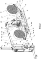
Figure 2 is a further perspective view of the feeding unit ofFigure 1 , where the feeding unit is sectioned through a vertical cross-section plane perpendicular to the axes of rotation of the reels; -
Figures 3 and4 are a front view and a rear view of the feeding unit ofFigure 1 , respectively; -
Figure 5 shows, on enlarged scale, the detail A ofFigure 2 ; and -
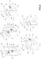
Figure 6 shows in sequence the operations of cutting of the two layers of the tissue web in use and joining of the same with the two layers of a new tissue web in a feeding unit according to the present invention. - Referring first to
Figures 1 to 4 , a feeding unit for feeding a tissue converting machine for converting a two-layer tissue web (such as a two-layer paper web) is generally indicated at 10. - Although reference is made in the following description to a two-layer tissue, the feeding unit of the invention is also capable of operating on tissue webs having more than two layers. The following description is thus also applicable to the case of a tissue web having more than two layers, since each of the two layers mentioned below may be in turn formed of two or more layers. The invention is not therefore to be intended as limited to the use of a two-layer tissue web, but also includes the case where the tissue web with which the machine is fed by the feeding unit of the invention is a tissue web having more than two layers.
- The
feeding unit 10 is arranged to unroll the two-layer tissue web (hereinafter simply referred to as web) from a reel and to eject it from an output O, facing the machine (which is of a known type and is therefore not shown in the drawings), with a given linear speed, for example equal to 600 m/min. Thefeeding unit 10 is further arranged to feed the machine continuously, i.e. without having to stop the machine when it is necessary to replace the spent reel with a new reel. To this end, as will be explained in more detail in the remaining part of the description, thefeeding unit 10 contains a pair of reels, indicated at R1 and R2, respectively, one of which is in use while the other serves to replace the first one when the latter is almost spent. In the example shown in the drawings, the reel in use is the reel R1, which is facing the side opposite to the output O, while the reel R2, placed on the same side as the output O, is intended to replace the reel R1 when the latter is almost spent. According to the invention, the transition from one reel to the other is achieved by joining the web (indicated at W2) of the new reel R2 to the web (indicated at W1) of the reel R1 in use, after cutting the latter, in particular by joining a first layer L1_2 of the new web W2 to a first layer L1_1 of the web W1 in use and joining the other layer L2_2 of the new web W2 to the other layer L2_1 of the web W1 in use. - The
feeding unit 10 comprises first of all a pair ofsupport uprights 12 for supporting each a respective reel R1, R2 in a freely rotatable manner about its axis. The axes of the two reels R1 and R2, indicated at x1 and x2, respectively, are oriented horizontally and parallel to each other. In addition, the axes x1 and x2 are oriented perpendicularly to the direction along which the web W1 in use leaves thefeeding unit 10 through the output O. Each reel R1, R2 is associated with anactuation device 14 arranged to drive the reel for rotation about its axis x1, x2 to cause the web W1, W2 to unroll from that reel. In the proposed embodiment, eachactuation device 14 controls the rotation of the respective reel R1, R2 by means of anendless belt 16 which is wound around a set of pulleys 18 (one of which acts as a driving pulley) and is held in contact against the side surface of the reel R1, R2 with a given force of contact. - The web W1 unrolled from the reel R1 is conveyed to the output O of the feeding unit along a given path defined by a plurality of
rollers 20 oriented with the respective axes of rotation parallel to the axes of rotation x1 and x2 of the two reels R1 and R2. Therollers 20 are supported by asupport frame 22, which has, for example, a portal-like structure comprising a first upright 24 and a second upright 26. The first and second reels R1 and R2 are arranged on opposite sides of the first upright 24, with the second reel R2 interposed between the first upright 24 and the second upright 26. - On the first upright 24 there is provided a cutting and joining unit, generally indicated at 28, which is arranged to cut the two layers L1_1 and L2_1 of the web W1 in use and to join each of the two layers L1_2 and L2_2 of the new web W2 to a respective layer of the first web W1. On the second upright 26 there is provided a web accumulation unit, generally indicated at 30, which is arranged to accumulate, before the cutting and joining
unit 28 performs the operations of cutting the web W1 in use and joining the new web W2 with the first web W1, a given quantity of web downstream of the cutting and joiningunit 28 to ensure that the machine continues to be fed with the web W1 while the portion of web W1 on which the cutting and joiningunit 28 acts is held temporarily stationary to allow the cutting and joining operations to be carried out. Theaccumulation unit 30 is of per-se-known type and will therefore not be described in further detail. - Referring also to
Figures 5 and6 , the web in use (in the illustrated example, the web W1) moves through the cutting and joiningdevice 28 along a substantially vertical direction, or a direction slightly inclined with respect to the vertical one. The cutting and joiningdevice 28 comprises first of all afirst cutting member 32, which is movable transversely (under control of suitable actuation means, which are of per-se-known type and are not shown in the drawings) with respect to the web W1 in use to cut one of the two layers of this web, namely the layer L1_1 facing the inside of the cutting and joining device 28 (hereinafter referred to simply as inner layer). Thefirst cutting member 32 is, for example, carried by avertical arm 36 slidably mounted on aguide profile 38 extending transversely to the web W1 (hence parallel to the axes x1 and x2 of the two reels R1 and R2). - According to an embodiment, the
first cutting member 32 comprises a wedge-shapedcentral element 34 having a pair ofsurfaces 34a inclined to one another and converging toward a substantiallyvertical edge 34b. A circular blade 39 (Figure 6 ), or similar cutting member, is rotatably mounted about a vertical axis of rotation on thecentral element 34. The rotation of theblade 39 about its axis is controlled by means of suitable actuation means, for example by means of an electric motor 41 (Figure 5 ). Thefirst cutting member 32 further comprises a pair of wedge-shaped side elements 40_1 and 40_2, arranged on opposite sides with respect to thecentral element 34. Each side element 40_1 and 40_2 cooperates with thesurface 34a of thecentral element 34 facing thereto to guide the inner layer L1_1 of the web W1 in use towards theblade 39 with a given orientation with respect to the blade itself. - The
first cutting member 32 is positioned with respect to the web portion passing through the cutting and joiningdevice 28 so that it may enter with one of the two side elements 40_1 and 40_2 between the two layers L1_1 and L2_1 to cut the inner layer L1_1. In the illustrated embodiment, in which the web in use is the web W1 that is unrolled from the reel R1, the transverse movement of thefirst cutting member 32 causes the first side element 40_1 to pass between the two layers L1_1 and L2_1 of the web, thus causing the inner layer L1_1, which is placed between the first side element 40_1 and thecentral element 34, to be cut. Naturally, when on the contrary the web in use is the web W2 that is unrolled from the reel R2, the transverse movement of thefirst cutting member 32 causes the second side element 40_2 to pass between the two layers L1_2 and L2_2 of the web, thereby causing the inner layer L2_2, which is placed between the second side element 40_2 and thecentral element 34, to be cut. - The cutting and joining
device 28 further comprises a pair of second cutting members 42 (only one of which is shown in the drawings, and specifically inFigure 6 ), which are arranged on opposite sides of thefirst cutting member 32 with respect to a plane parallel to the web W1 in use and are both movable (under the control of suitable actuation means, which are of per-se-known type and are not shown in the drawings) transversely with respect to the web W1 in use to cut the other layer (i.e. the layer L2_1) of such web, i.e. to cut the layer facing the outside of the cutting and joining device 28 (hereinafter referred to as outer layer). - As can be seen by observing
Figure 6 , thesecond cutting members 42 are also positioned vertically spaced with respect to thefirst cutting member 32 so as to cut the outer layer L2_1 of the web W1 in use along a cut line that is vertically spaced (therefore spaced along the longitudinal direction of the web W1) from the cut line along which thefirst cutting member 32 cuts the inner layer L1_1. More specifically, thefirst cutting member 32 is positioned above thesecond cutting members 42, so that the inner layer L1_1 of the web W1 in use is cut along a cut line positioned above the cut line along which the outer layer L2_1 is cut (or, more generally, positioned downstream of this cut line, with respect to the feeding direction of the web W1). - Still with reference to
Figure 6 , according to an embodiment of the invention eachsecond cutting member 42 comprises acircular blade 43, or similar cutting element, which is rotatably mounted about a vertical axis of rotation and is controllable in rotation about said axis by means of suitable actuation means, for example by means of anelectric motor 45. - Each
second cutting member 42 further comprises a separatingelement 47, made for example as a tab, having the function of separating the two layers L1_1 and L2_1 of the web W1 in use. Thesecond cutting member 42 associated with the web W1 in use is normally kept in a position such that the separatingelement 47 slightly penetrates (e.g., one or two centimeters) inside the web W1 between the two layers L1_1 and L2_1 so as to keep the two layers detached from each other along the side edge of the web W1. - To summarize, therefore, both when the web in use is the web W1 that is being unrolled from the first reel R1 and when the web in use is the web W2 that is being unrolled from the second reel R2, the cutting and joining
device 28 is arranged to cut the two layers of the web in use along cut lines spaced apart from each other in the longitudinal direction of the web, and specifically with the cut line of the inner layer positioned above the cut line of the outer layer. Cutting of the web W1 is preferably carried out by first cutting the outer layer L2_1 by means of thesecond cutting member 42 and then by cutting also the inner layer L1_1 by means of thefirst cutting member 32. - The cutting and joining
device 28 is also arranged to join the two layers L1_1 and L2_1 of the web in use (in this case the web W1) once they have been cut by the first cuttingmember 32 and by thesecond cutting member 42 in the manner described above, each with a respective layer L1_2 and L2_2 of the new web (in this case the web W2). - To this end, according to an embodiment of the invention the cutting and joining
device 28 further comprises a pair of plates 44_1 and 44_2 which are arranged on opposite sides with respect to the portion of web W1 in use that passes through the cutting and joiningdevice 28 and are each carried by a respective support structure 46_1 and 46_2 mounted on thefirst upright 24 so as to be able to tilt about a horizontal axis of rotation parallel to the axes x1 and x2 between a rest position and a working position. The plate 44_1 and the respective support structure 46_1 are arranged on the same side as the reel R1, while the plate 44_2 and the respective support structure 46_2 are arranged on the same side as the reel R2. In the normal operating condition, the support structures 46_1 and 46_2 with the respective plates 44_1 and 44_2 are kept in the working position, where they are arranged vertically. - The support structure 46_2 with the respective plate 44_2 is shown in the drawings in the rest position, where it is arranged horizontally or slightly inclined to the horizontal. With the support structure 46_2 and the respective plate 44_2 in that position, the operator positions and locks the leading edges of the two layers L1_2 and L2_2 of the new web W2 on the plate 44_2 at a distance from each other equal to the distance between the cut lines along which the two layers L1_1 and L2_1 of the web W1 in use are cut by the first cutting
member 32 and by thesecond cutting member 42. This operation is performed manually by the operator while thefeeding unit 10 is feeding the machine with the web W1, so that when the web W1 is almost spent the new web W2 is ready to be joined to the web W1 to ensure continuous feeding of the machine. On the leading edges of the two layers L1_2 and L2_2 of the web W2, on the upwardly facing side, a layer of adhesive 52 (e.g. a double-sided adhesive tape) is applied to allow each layer of said web to be attached to the respective layer of the other web W1. - Once the spent web W1 has been cut in the manner described above, the two plates 44_1 and 44_2 are urged against each other so as to press the leading edges of the two layers L1_2 and L2_2 of the new web W2 (on which the
adhesive layer 52 is applied) against the end edges of the two layers L1_1 and L2_1 of the web W1 and thus join each layer of the new web W2 to the respective layer of the web W1. To this end, each support structure 46_1, 46_2 compriseslinear guides 48 for guiding the respective plate 44_1, 44_2 in the translational movement in a direction perpendicular to its plane and alinear actuator 50, made for example as a pneumatic cylinder, for controlling the movement of the respective plate 44_1, 44_2 in a direction perpendicular to its plane. - The cutting and joining operation is therefore carried out by the cutting and joining
device 28 as follows, assuming that the web in use is the web W1 that is being unrolled from the reel R1. - Before the web W1 in use is spent, the new web W2 is prepared to be joined to the web W1. To this end, the operator places on the plate 44_2 of the support structure 46_2 (with the latter placed in the rest position) the two layers L1_2 and L2_2 of the new web W2 with the respective leading edges spaced from each other at a distance equal to the distance between the cut lines along which the first cutting
member 32 and thesecond cutting member 42 are arranged to cut the two layers L1_1 and L2_1 of the web W1 in use, in particular with the inner layer L1_2 of the new web W2 shorter than the outer layer L2_2. The operator also applies a layer of adhesive 52 near the leading edges of both the layers L1_2 and L2_2 of the new web W2. When the web W1 in use is nearly spent, theaccumulation unit 30 is controlled to accumulate a given amount of web downstream of the cutting and joiningunit 28. Thereafter, the cutting and joiningunit 28 is controlled to perform in succession the operations of cutting the web W1 in use and joining the new web W2 to the web W1. In this connection, the two layers L1_1 and L2_1 of the web W1 in use (which to this end is temporarily stopped) are cut by the first cuttingmember 32 and by thesecond cutting member 42 along respective cut lines spaced apart from one another and then the plate 44_1 of the support structure 46_1 is pushed against the plate 44_2 of the other support structure 46_2 so as to press the final end portion of each of the two layers L1_1 and L2_1 of the web W1 in use against the leading end portion of the respective layer L1_2 and L2_2 of the new web W2, thereby making these portions adhere to each other due to theadhesive layer 52 previously applied on the new web W2. At this point, thefeeding unit 10 is ready to feed the machine with the new web W2. As can be seen from the above description, the transition from the condition where the machine is being fed with the web W1 to the condition where the machine is being fed with the new web W2 occurs with no interruptions in the feeding of the machine, which undoubtedly leads to an increase in the productivity of the machine. - Naturally, the principle of the invention remaining unchanged, the embodiments and constructional details may be greatly varied with respect to those described and illustrated here purely by way of a non-limiting example, without thereby departing from the scope of the invention as defined in the accompanying claims.
wherein said first cutting member is placed downstream of said second cutting members with respect to the feeding direction of the tissue web in use, and
wherein each of said second cutting members comprises a separating element adapted to be inserted between the two layers of the tissue web in use to keep said layers detached from each other along a side edge of the tissue web in use.
Claims (5)
- Feeding unit (10) for feeding a tissue converting machine for converting a web (W1, W2) of two-layer tissue, the feeding unit (10) comprising:- support means (12) for rotatably supporting a first reel (R1) of two-layer tissue web and a second reel (R2) of two-layer tissue web for rotation about respective axes of rotation (x1, x2);- cutting means (32, 42) for cutting the two layers (L1_1, L2_1) of the tissue web (W1) of one (R1) of said first and second reels (R1, R2), namely the reel in use, said cutting means (32, 42) being configured to cut the two layers (L1_1, L2_1) of the tissue web (W1) along two cut lines spaced from each other in the longitudinal direction of the web (W1);- joining means (44_1, 44_2) for joining each of the two layers (L1_2, L2_2) of the tissue web (W2) of the other one (R2) of said first and second reels (R1, R2), namely the new reel, to a respective layer (L1_1, L2_1) of the tissue web (W1) of the reel (R1) in use; and- tissue web accumulation means (30) for accumulating a given amount of tissue web (W1) downstream of the cutting means (32, 42) and of the joining means (44_1, 44_2) so as to ensure that the machine is fed with the tissue web (W1) while the portion of tissue web (W1) on which the cutting means (32, 42) and the joining means (44_1, 44_2) act is kept temporarily still to allow cutting of the two layers (L1_1, L2_1) of the tissue web (W1) in use and joining of these layers to the two layers (L1_2, L2_2) of the new tissue web (W2),
wherein said cutting means (32, 42) comprise a first cutting member (32) for cutting the inner layer (L1_1) of the tissue web (W1) in use and a pair of second cutting members (42) which are placed on opposite sides of the first cutting member (32) with respect to a plane parallel to the web (W1) in use and are arranged to cut the outer layer (L2_1) of the tissue web (W1) in use, said second cutting members (42) being positioned at a distance from said first cutting member (32) in the longitudinal direction of the tissue web (W1) in use, wherein said first cutting member (32) is placed downstream of said second cutting members (42) with respect to the feeding direction of the tissue web (W1) in use, and wherein each of said second cutting members (42) comprises a separating element (47) adapted to be inserted between the two layers (L1_1, L2_1) of the tissue web (W1) in use to keep said layers (L1_1, L2_1) detached from each other along a side edge of the tissue web (W1) in use. - Feeding unit according to claim 1, wherein said first cutting member (32) comprises a wedge-shaped central element (34), with a pair of surfaces (34a) inclined to each other so as to converge towards an edge (34b), a first cutting member (39) rotatably mounted on the central element (34) for rotation about an axis of rotation, first actuation means (41) for controlling the rotation of said first cutting member (39) about its axis of rotation, and a pair of wedge-shaped side elements (40_1, 40_2), which are placed on opposite sides with respect to the central element (34) and are arranged to cooperate each with the surface (34a) of the central element (34) facing thereto to guide the inner layer (L1_1) of the web (W1) in use towards said first cutting member (39).
- Feeding unit according to claim 1 or claim 2, wherein each of said second cutting members (42) further comprises a second cutting element (43) rotatably mounted about an axis of rotation, second actuation means (45) for controlling the rotation of said second cutting element (43) about its axis of rotation.
- Feeding unit according to any of the preceding claims, wherein said joining means (44_1, 44_2) comprise a pair of plates (44_1, 44_2) arranged to be urged against each other to clamp the tissue web (W1) in use with the new tissue web (W2).
- Feeding unit according to any of the preceding claims, further comprising a support frame (22) on which a plurality of rollers (20) are rotatably mounted, which rollers are oriented with the respective axes of rotation parallel to the axes of rotation (x1, x2) of the first and second reels (R1, R2) and are arranged to define the path of the tissue web (W1) in use towards an outlet (O) of the feeding unit, said path being oriented vertically, or mainly vertically, through a length thereof where said cutting means (32, 42) and said joining means (44_1, 44_2) are arranged to operate.
Priority Applications (2)
| Application Number | Priority Date | Filing Date | Title |
|---|---|---|---|
| RS20200608A RS60361B1 (en) | 2016-07-26 | 2017-07-25 | Feeding unit for a tissue converting machine for converting a web of two-layer tissue |
| PL17748951T PL3490919T3 (en) | 2016-07-26 | 2017-07-25 | Feeding unit for a tissue converting machine for converting a web of two-layer tissue |
Applications Claiming Priority (2)
| Application Number | Priority Date | Filing Date | Title |
|---|---|---|---|
| IT102016000078303A IT201600078303A1 (en) | 2016-07-26 | 2016-07-26 | Feeding unit for a machine for converting a strip of two-ply material. |
| PCT/IB2017/054494 WO2018020410A1 (en) | 2016-07-26 | 2017-07-25 | Feeding unit for a tissue converting machine for converting a web of two-layer tissue |
Publications (2)
| Publication Number | Publication Date |
|---|---|
| EP3490919A1 EP3490919A1 (en) | 2019-06-05 |
| EP3490919B1 true EP3490919B1 (en) | 2020-05-13 |
Family
ID=58159189
Family Applications (1)
| Application Number | Title | Priority Date | Filing Date |
|---|---|---|---|
| EP17748951.5A Active EP3490919B1 (en) | 2016-07-26 | 2017-07-25 | Feeding unit for a tissue converting machine for converting a web of two-layer tissue |
Country Status (18)
| Country | Link |
|---|---|
| US (1) | US11472654B2 (en) |
| EP (1) | EP3490919B1 (en) |
| JP (1) | JP7057773B2 (en) |
| CN (1) | CN109689547B (en) |
| AR (1) | AR109160A1 (en) |
| BR (1) | BR112019001545B1 (en) |
| CA (1) | CA3031383A1 (en) |
| CL (1) | CL2019000166A1 (en) |
| DK (1) | DK3490919T3 (en) |
| ES (1) | ES2806952T3 (en) |
| HU (1) | HUE051072T2 (en) |
| IT (1) | IT201600078303A1 (en) |
| MX (1) | MX2019001130A (en) |
| PL (1) | PL3490919T3 (en) |
| PT (1) | PT3490919T (en) |
| RS (1) | RS60361B1 (en) |
| TW (1) | TWI742116B (en) |
| WO (1) | WO2018020410A1 (en) |
Families Citing this family (2)
| Publication number | Priority date | Publication date | Assignee | Title |
|---|---|---|---|---|
| CN110422666B (en) * | 2019-07-26 | 2024-03-26 | 河北万达轮胎有限公司 | Belt film isolating film coiling device |
| CN114521822A (en) | 2022-03-17 | 2022-05-24 | 桐乡市蜗殒供应链管理有限公司 | Reusable fixed tissue holder |
Family Cites Families (18)
| Publication number | Priority date | Publication date | Assignee | Title |
|---|---|---|---|---|
| US5190234A (en) * | 1988-12-06 | 1993-03-02 | Butler Automatic, Inc. | Web handling method and apparatus with pre-acceleration of web feed rolls |
| SE466055B (en) * | 1990-04-18 | 1991-12-09 | Duni Ab | SEAT AND DEVICE FOR SHARPING AT LEAST TWO OF SINGLE OR MULTILAYER MATERIALS EXISTING AIR PERSPECTIVE TAPE PAPERS |
| ES2274911T3 (en) * | 2000-11-17 | 2007-06-01 | Ranpak Corp. | PROCEDURE FOR LOADING A MACHINE FOR THE CONVERSION OF PADDING THAT INCLUDES SUPPLY OF RAW MATERIAL. |
| JP2003252495A (en) * | 2002-03-04 | 2003-09-10 | Orion Kikai Kogyo Kk | Method and device for connecting sheets of paper |
| US6817566B2 (en) * | 2002-10-30 | 2004-11-16 | Butler Automatic, Inc. | Web splicer |
| US20050241774A1 (en) * | 2004-04-30 | 2005-11-03 | Kimberly-Clark Worldwide, Inc. | Apparatus and process for aligning materials during a splice |
| DE102008009958B3 (en) * | 2008-02-20 | 2009-05-14 | Paprima Industries Inc., Dorval | Method for protecting web end of paper wed, involves changing of one reel to another reel, where web end runs between paper roller and latter reel |
| TWI385116B (en) * | 2008-11-21 | 2013-02-11 | Chan Li Machinery Co Ltd | A paper roll winding mechanism with a grooved scraper and a gumming method |
| JP5218780B2 (en) * | 2009-10-28 | 2013-06-26 | トヨタ自動車株式会社 | How to replace old and new roll material wound with multi-layer long tape |
| JP2011116513A (en) * | 2009-12-04 | 2011-06-16 | Unicharm Corp | Strip supply device and operating method of the same |
| JP5202612B2 (en) * | 2010-11-30 | 2013-06-05 | 池田機械産業株式会社 | Raw material splicing equipment |
| ITVR20140052A1 (en) * | 2013-07-16 | 2015-01-17 | Sacmi Verona Spa | Labeling machine for labeling of products to be labeled |
| ITMI20131883A1 (en) * | 2013-11-13 | 2015-05-14 | Cannon Spa | APPARATUS AND METHOD FOR FEEDING TAPE MATERIAL FOR PANEL FOAMING |
| US9981821B2 (en) * | 2015-02-19 | 2018-05-29 | Tecnau S.R.L. | Splicing equipment for strips wound on a pair of spools |
| DE102015218321A1 (en) * | 2015-09-24 | 2017-03-30 | Bhs Corrugated Maschinen- Und Anlagenbau Gmbh | Splicevorrichtung |
| DE102016205059A1 (en) * | 2016-03-24 | 2017-09-28 | Bhs Corrugated Maschinen- Und Anlagenbau Gmbh | Spliceanordnung |
| ITUA20162470A1 (en) * | 2016-04-11 | 2017-10-11 | Guangdong Fosber Intelligent Equipment Co Ltd | JUNCTION MATERIAL OF JUNCTION MATERIALS, UNWINDER UNDERSTANDING THE JUNCTION DEVICE, AND OPERATING METHOD |
| DE102016206446A1 (en) * | 2016-04-15 | 2017-10-19 | Bhs Corrugated Maschinen- Und Anlagenbau Gmbh | Spliceanordnung |
-
2016
- 2016-07-26 IT IT102016000078303A patent/IT201600078303A1/en unknown
-
2017
- 2017-07-25 PL PL17748951T patent/PL3490919T3/en unknown
- 2017-07-25 PT PT177489515T patent/PT3490919T/en unknown
- 2017-07-25 WO PCT/IB2017/054494 patent/WO2018020410A1/en unknown
- 2017-07-25 US US16/319,048 patent/US11472654B2/en active Active
- 2017-07-25 CN CN201780046442.1A patent/CN109689547B/en active Active
- 2017-07-25 EP EP17748951.5A patent/EP3490919B1/en active Active
- 2017-07-25 HU HUE17748951A patent/HUE051072T2/en unknown
- 2017-07-25 ES ES17748951T patent/ES2806952T3/en active Active
- 2017-07-25 CA CA3031383A patent/CA3031383A1/en active Pending
- 2017-07-25 MX MX2019001130A patent/MX2019001130A/en unknown
- 2017-07-25 DK DK17748951.5T patent/DK3490919T3/en active
- 2017-07-25 RS RS20200608A patent/RS60361B1/en unknown
- 2017-07-25 BR BR112019001545-0A patent/BR112019001545B1/en active IP Right Grant
- 2017-07-25 JP JP2019503747A patent/JP7057773B2/en active Active
- 2017-07-26 AR ARP170102103A patent/AR109160A1/en active IP Right Grant
- 2017-07-26 TW TW106125015A patent/TWI742116B/en active
-
2019
- 2019-01-21 CL CL2019000166A patent/CL2019000166A1/en unknown
Non-Patent Citations (1)
| Title |
|---|
| None * |
Also Published As
| Publication number | Publication date |
|---|---|
| BR112019001545A2 (en) | 2019-05-14 |
| TWI742116B (en) | 2021-10-11 |
| PT3490919T (en) | 2020-07-14 |
| TW201808765A (en) | 2018-03-16 |
| CA3031383A1 (en) | 2018-02-01 |
| US11472654B2 (en) | 2022-10-18 |
| ES2806952T3 (en) | 2021-02-19 |
| CN109689547A (en) | 2019-04-26 |
| RS60361B1 (en) | 2020-07-31 |
| JP7057773B2 (en) | 2022-04-20 |
| IT201600078303A1 (en) | 2018-01-26 |
| US20210371226A1 (en) | 2021-12-02 |
| CN109689547B (en) | 2020-11-13 |
| WO2018020410A1 (en) | 2018-02-01 |
| PL3490919T3 (en) | 2020-11-16 |
| HUE051072T2 (en) | 2021-03-01 |
| MX2019001130A (en) | 2019-08-21 |
| JP2019527656A (en) | 2019-10-03 |
| CL2019000166A1 (en) | 2019-08-09 |
| EP3490919A1 (en) | 2019-06-05 |
| AR109160A1 (en) | 2018-11-07 |
| BR112019001545B1 (en) | 2022-11-29 |
| DK3490919T3 (en) | 2020-06-02 |
Similar Documents
| Publication | Publication Date | Title |
|---|---|---|
| US6547909B1 (en) | Flying web splice apparatus and method | |
| EP0882412B1 (en) | Composite web forming apparatus and method | |
| US20070163699A1 (en) | Process and device for processing a film web | |
| NZ201962A (en) | Splicing webs | |
| CN108883543B (en) | Separating device for separating sections from a material web, laminating machine having a separating device, and method for separating at least one section from a material web | |
| US20080216449A1 (en) | Banding a Stack of Products Which are to be Stacked | |
| EP2233399B1 (en) | Horizontal packaging machine including an unwinder with a splicing device for changing reels without stopping the machine, and a band supply unit applicable to said machine | |
| EP3490919B1 (en) | Feeding unit for a tissue converting machine for converting a web of two-layer tissue | |
| CN105398863A (en) | Label sheet slitting apparatus | |
| US6966961B2 (en) | Splicing device for splicing two web materials together, unwinder comprising said splicing device and relative method | |
| US7621479B2 (en) | Supply-roll switching apparatus | |
| ITBO930112A1 (en) | METHOD AND DEVICE FOR THE AUTOMATIC JOINTING OF TAPES PERFORMED BY REELS. | |
| WO2015071839A1 (en) | Apparatus and method for feeding web material for foaming of panels | |
| CN110615303A (en) | Automatic belt splicing device | |
| DE202014101731U1 (en) | Documenting device for placing a rubberized band on a cord, in particular steel or textile cord | |
| US6308908B1 (en) | Machine for coiling a flat continuous element to form rolls | |
| PL210369B1 (en) | Method of appliance designed to join ribbons of material | |
| US8500057B2 (en) | Method and apparatus for threading a fibrous material web in a winder | |
| CN109773840A (en) | Feeding device | |
| KR102219005B1 (en) | Slitter for cutting cord band | |
| WO2007107627A1 (en) | Method in connection with a slitter-winder | |
| CN203486619U (en) | Transmission system and weaving equipment with the transmission system | |
| CN211110242U (en) | Unwinding mechanism and cutting machine | |
| KR20140012867A (en) | Apparatus for shifting paper jointing tube | |
| ITBO970152A1 (en) | EQUIPMENT FOR FEEDING A FILM OF THERMOFORM BILE MATERIAL INTO PACKAGING MACHINES OF PRODUCTS IN BLISTERS AND SIMILAR |
Legal Events
| Date | Code | Title | Description |
|---|---|---|---|
| STAA | Information on the status of an ep patent application or granted ep patent |
Free format text: STATUS: UNKNOWN |
|
| STAA | Information on the status of an ep patent application or granted ep patent |
Free format text: STATUS: THE INTERNATIONAL PUBLICATION HAS BEEN MADE |
|
| PUAI | Public reference made under article 153(3) epc to a published international application that has entered the european phase |
Free format text: ORIGINAL CODE: 0009012 |
|
| STAA | Information on the status of an ep patent application or granted ep patent |
Free format text: STATUS: REQUEST FOR EXAMINATION WAS MADE |
|
| 17P | Request for examination filed |
Effective date: 20190222 |
|
| AK | Designated contracting states |
Kind code of ref document: A1 Designated state(s): AL AT BE BG CH CY CZ DE DK EE ES FI FR GB GR HR HU IE IS IT LI LT LU LV MC MK MT NL NO PL PT RO RS SE SI SK SM TR |
|
| AX | Request for extension of the european patent |
Extension state: BA ME |
|
| DAV | Request for validation of the european patent (deleted) | ||
| DAX | Request for extension of the european patent (deleted) | ||
| GRAP | Despatch of communication of intention to grant a patent |
Free format text: ORIGINAL CODE: EPIDOSNIGR1 |
|
| STAA | Information on the status of an ep patent application or granted ep patent |
Free format text: STATUS: GRANT OF PATENT IS INTENDED |
|
| INTG | Intention to grant announced |
Effective date: 20191128 |
|
| GRAS | Grant fee paid |
Free format text: ORIGINAL CODE: EPIDOSNIGR3 |
|
| GRAL | Information related to payment of fee for publishing/printing deleted |
Free format text: ORIGINAL CODE: EPIDOSDIGR3 |
|
| GRAS | Grant fee paid |
Free format text: ORIGINAL CODE: EPIDOSNIGR3 |
|
| GRAA | (expected) grant |
Free format text: ORIGINAL CODE: 0009210 |
|
| STAA | Information on the status of an ep patent application or granted ep patent |
Free format text: STATUS: THE PATENT HAS BEEN GRANTED |
|
| AK | Designated contracting states |
Kind code of ref document: B1 Designated state(s): AL AT BE BG CH CY CZ DE DK EE ES FI FR GB GR HR HU IE IS IT LI LT LU LV MC MK MT NL NO PL PT RO RS SE SI SK SM TR |
|
| REG | Reference to a national code |
Ref country code: GB Ref legal event code: FG4D |
|
| REG | Reference to a national code |
Ref country code: CH Ref legal event code: EP |
|
| REG | Reference to a national code |
Ref country code: FI Ref legal event code: FGE |
|
| REG | Reference to a national code |
Ref country code: DK Ref legal event code: T3 Effective date: 20200529 |
|
| REG | Reference to a national code |
Ref country code: DE Ref legal event code: R096 Ref document number: 602017016665 Country of ref document: DE |
|
| REG | Reference to a national code |
Ref country code: AT Ref legal event code: REF Ref document number: 1269996 Country of ref document: AT Kind code of ref document: T Effective date: 20200615 |
|
| REG | Reference to a national code |
Ref country code: NL Ref legal event code: FP |
|
| REG | Reference to a national code |
Ref country code: SE Ref legal event code: TRGR |
|
| REG | Reference to a national code |
Ref country code: PT Ref legal event code: SC4A Ref document number: 3490919 Country of ref document: PT Date of ref document: 20200714 Kind code of ref document: T Free format text: AVAILABILITY OF NATIONAL TRANSLATION Effective date: 20200707 |
|
| REG | Reference to a national code |
Ref country code: GR Ref legal event code: EP Ref document number: 20200401553 Country of ref document: GR Effective date: 20200716 |
|
| REG | Reference to a national code |
Ref country code: SK Ref legal event code: T3 Ref document number: E 34368 Country of ref document: SK Ref country code: NO Ref legal event code: T2 Effective date: 20200513 |
|
| REG | Reference to a national code |
Ref country code: LT Ref legal event code: MG4D |
|
| PG25 | Lapsed in a contracting state [announced via postgrant information from national office to epo] |
Ref country code: LT Free format text: LAPSE BECAUSE OF FAILURE TO SUBMIT A TRANSLATION OF THE DESCRIPTION OR TO PAY THE FEE WITHIN THE PRESCRIBED TIME-LIMIT Effective date: 20200513 Ref country code: IS Free format text: LAPSE BECAUSE OF FAILURE TO SUBMIT A TRANSLATION OF THE DESCRIPTION OR TO PAY THE FEE WITHIN THE PRESCRIBED TIME-LIMIT Effective date: 20200913 |
|
| PG25 | Lapsed in a contracting state [announced via postgrant information from national office to epo] |
Ref country code: BG Free format text: LAPSE BECAUSE OF FAILURE TO SUBMIT A TRANSLATION OF THE DESCRIPTION OR TO PAY THE FEE WITHIN THE PRESCRIBED TIME-LIMIT Effective date: 20200813 Ref country code: LV Free format text: LAPSE BECAUSE OF FAILURE TO SUBMIT A TRANSLATION OF THE DESCRIPTION OR TO PAY THE FEE WITHIN THE PRESCRIBED TIME-LIMIT Effective date: 20200513 Ref country code: HR Free format text: LAPSE BECAUSE OF FAILURE TO SUBMIT A TRANSLATION OF THE DESCRIPTION OR TO PAY THE FEE WITHIN THE PRESCRIBED TIME-LIMIT Effective date: 20200513 |
|
| PG25 | Lapsed in a contracting state [announced via postgrant information from national office to epo] |
Ref country code: AL Free format text: LAPSE BECAUSE OF FAILURE TO SUBMIT A TRANSLATION OF THE DESCRIPTION OR TO PAY THE FEE WITHIN THE PRESCRIBED TIME-LIMIT Effective date: 20200513 |
|
| PG25 | Lapsed in a contracting state [announced via postgrant information from national office to epo] |
Ref country code: RO Free format text: LAPSE BECAUSE OF FAILURE TO SUBMIT A TRANSLATION OF THE DESCRIPTION OR TO PAY THE FEE WITHIN THE PRESCRIBED TIME-LIMIT Effective date: 20200513 Ref country code: EE Free format text: LAPSE BECAUSE OF FAILURE TO SUBMIT A TRANSLATION OF THE DESCRIPTION OR TO PAY THE FEE WITHIN THE PRESCRIBED TIME-LIMIT Effective date: 20200513 Ref country code: SM Free format text: LAPSE BECAUSE OF FAILURE TO SUBMIT A TRANSLATION OF THE DESCRIPTION OR TO PAY THE FEE WITHIN THE PRESCRIBED TIME-LIMIT Effective date: 20200513 |
|
| REG | Reference to a national code |
Ref country code: DE Ref legal event code: R097 Ref document number: 602017016665 Country of ref document: DE |
|
| REG | Reference to a national code |
Ref country code: ES Ref legal event code: FG2A Ref document number: 2806952 Country of ref document: ES Kind code of ref document: T3 Effective date: 20210219 |
|
| PG25 | Lapsed in a contracting state [announced via postgrant information from national office to epo] |
Ref country code: MC Free format text: LAPSE BECAUSE OF FAILURE TO SUBMIT A TRANSLATION OF THE DESCRIPTION OR TO PAY THE FEE WITHIN THE PRESCRIBED TIME-LIMIT Effective date: 20200513 |
|
| REG | Reference to a national code |
Ref country code: CH Ref legal event code: PL |
|
| REG | Reference to a national code |
Ref country code: HU Ref legal event code: AG4A Ref document number: E051072 Country of ref document: HU |
|
| PLBE | No opposition filed within time limit |
Free format text: ORIGINAL CODE: 0009261 |
|
| STAA | Information on the status of an ep patent application or granted ep patent |
Free format text: STATUS: NO OPPOSITION FILED WITHIN TIME LIMIT |
|
| 26N | No opposition filed |
Effective date: 20210216 |
|
| PG25 | Lapsed in a contracting state [announced via postgrant information from national office to epo] |
Ref country code: LI Free format text: LAPSE BECAUSE OF NON-PAYMENT OF DUE FEES Effective date: 20200731 Ref country code: LU Free format text: LAPSE BECAUSE OF NON-PAYMENT OF DUE FEES Effective date: 20200725 Ref country code: CH Free format text: LAPSE BECAUSE OF NON-PAYMENT OF DUE FEES Effective date: 20200731 |
|
| PG25 | Lapsed in a contracting state [announced via postgrant information from national office to epo] |
Ref country code: SI Free format text: LAPSE BECAUSE OF FAILURE TO SUBMIT A TRANSLATION OF THE DESCRIPTION OR TO PAY THE FEE WITHIN THE PRESCRIBED TIME-LIMIT Effective date: 20200513 |
|
| PG25 | Lapsed in a contracting state [announced via postgrant information from national office to epo] |
Ref country code: IE Free format text: LAPSE BECAUSE OF NON-PAYMENT OF DUE FEES Effective date: 20200725 |
|
| REG | Reference to a national code |
Ref country code: AT Ref legal event code: UEP Ref document number: 1269996 Country of ref document: AT Kind code of ref document: T Effective date: 20200513 |
|
| PG25 | Lapsed in a contracting state [announced via postgrant information from national office to epo] |
Ref country code: MT Free format text: LAPSE BECAUSE OF FAILURE TO SUBMIT A TRANSLATION OF THE DESCRIPTION OR TO PAY THE FEE WITHIN THE PRESCRIBED TIME-LIMIT Effective date: 20200513 Ref country code: CY Free format text: LAPSE BECAUSE OF FAILURE TO SUBMIT A TRANSLATION OF THE DESCRIPTION OR TO PAY THE FEE WITHIN THE PRESCRIBED TIME-LIMIT Effective date: 20200513 |
|
| PG25 | Lapsed in a contracting state [announced via postgrant information from national office to epo] |
Ref country code: MK Free format text: LAPSE BECAUSE OF FAILURE TO SUBMIT A TRANSLATION OF THE DESCRIPTION OR TO PAY THE FEE WITHIN THE PRESCRIBED TIME-LIMIT Effective date: 20200513 |
|
| P01 | Opt-out of the competence of the unified patent court (upc) registered |
Effective date: 20230525 |
|
| PGFP | Annual fee paid to national office [announced via postgrant information from national office to epo] |
Ref country code: RS Payment date: 20230518 Year of fee payment: 7 Ref country code: IT Payment date: 20230504 Year of fee payment: 7 Ref country code: CZ Payment date: 20230519 Year of fee payment: 7 |
|
| PGFP | Annual fee paid to national office [announced via postgrant information from national office to epo] |
Ref country code: PL Payment date: 20230522 Year of fee payment: 7 Ref country code: NL Payment date: 20230726 Year of fee payment: 7 |
|
| PGFP | Annual fee paid to national office [announced via postgrant information from national office to epo] |
Ref country code: TR Payment date: 20230724 Year of fee payment: 7 Ref country code: NO Payment date: 20230717 Year of fee payment: 7 Ref country code: GB Payment date: 20230721 Year of fee payment: 7 Ref country code: FI Payment date: 20230713 Year of fee payment: 7 Ref country code: ES Payment date: 20230801 Year of fee payment: 7 Ref country code: AT Payment date: 20230718 Year of fee payment: 7 |
|
| PGFP | Annual fee paid to national office [announced via postgrant information from national office to epo] |
Ref country code: SK Payment date: 20230719 Year of fee payment: 7 Ref country code: SE Payment date: 20230720 Year of fee payment: 7 Ref country code: PT Payment date: 20230713 Year of fee payment: 7 Ref country code: HU Payment date: 20230721 Year of fee payment: 7 Ref country code: GR Payment date: 20230721 Year of fee payment: 7 Ref country code: FR Payment date: 20230727 Year of fee payment: 7 Ref country code: DK Payment date: 20230721 Year of fee payment: 7 Ref country code: DE Payment date: 20230719 Year of fee payment: 7 Ref country code: BE Payment date: 20230719 Year of fee payment: 7 |