EP3490810B1 - Vehicle traction enhancement - Google Patents
Vehicle traction enhancement Download PDFInfo
- Publication number
- EP3490810B1 EP3490810B1 EP17745861.9A EP17745861A EP3490810B1 EP 3490810 B1 EP3490810 B1 EP 3490810B1 EP 17745861 A EP17745861 A EP 17745861A EP 3490810 B1 EP3490810 B1 EP 3490810B1
- Authority
- EP
- European Patent Office
- Prior art keywords
- gas
- road surface
- vehicle
- deflector
- gas outlet
- Prior art date
- Legal status (The legal status is an assumption and is not a legal conclusion. Google has not performed a legal analysis and makes no representation as to the accuracy of the status listed.)
- Active
Links
Images



Classifications
-
- B—PERFORMING OPERATIONS; TRANSPORTING
- B60—VEHICLES IN GENERAL
- B60B—VEHICLE WHEELS; CASTORS; AXLES FOR WHEELS OR CASTORS; INCREASING WHEEL ADHESION
- B60B39/00—Increasing wheel adhesion
- B60B39/02—Vehicle fittings for scattering or dispensing material in front of its wheels
- B60B39/021—Details of the dispensing device
- B60B39/025—Details of the dispensing device related to the control system
-
- B—PERFORMING OPERATIONS; TRANSPORTING
- B60—VEHICLES IN GENERAL
- B60B—VEHICLE WHEELS; CASTORS; AXLES FOR WHEELS OR CASTORS; INCREASING WHEEL ADHESION
- B60B39/00—Increasing wheel adhesion
- B60B39/02—Vehicle fittings for scattering or dispensing material in front of its wheels
- B60B39/021—Details of the dispensing device
- B60B39/022—Details of the dispensing device related to reservoirs
-
- B—PERFORMING OPERATIONS; TRANSPORTING
- B60—VEHICLES IN GENERAL
- B60B—VEHICLE WHEELS; CASTORS; AXLES FOR WHEELS OR CASTORS; INCREASING WHEEL ADHESION
- B60B39/00—Increasing wheel adhesion
- B60B39/02—Vehicle fittings for scattering or dispensing material in front of its wheels
- B60B39/026—Vehicle fittings for scattering or dispensing material in front of its wheels the material being in gas form
Definitions
- the present disclosure relates to apparatus for improving traction for vehicles travelling in wet or otherwise slippery conditions.
- US3544370 describes the combined use of a deflector and a nozzle for supplying gas to a road surface.
- the present disclosure aims to provide a system, external to the tyre, which provides an opportunity to reduce the effect of wet road surfaces and can offer opportunities to remove some constraints in tyre design and to pursue further reductions in tyre rolling resistance.
- the present invention provides apparatus on a wheeled vehicle as claimed in claim 1.
- the invention When viewed from another aspect the invention provides apparatus for a wheeled vehicle as claimed in claim 15.
- a gas source is able to supply a burst of gas which can move and / or lift surface water and other debris from the road.
- the opportunity to provide a dry road surface in front of tyres offers a significant improvement to vehicle safety.
- the forces generated in a tyre contact patch control traction, braking and cornering. These forces are greatly compromised by road surface contamination, which is mostly in the form of surface water following rain. In serious weather conditions aquaplaning can still occur, despite the advanced tread design of modern tyres.
- a dry road surface in front of a tyre will limit the possibility of aquaplaning.
- braking distances are adversely affected.
- Providing a dry road surface in front of the tyre will reduce braking distance, thus enhancing safety. This is particularly important in the event of emergency braking.
- the burst of gas could therefore be deployed when anti-lock brakes are employed for example.
- the system may also assist in preventing loss of control on snow, slush, mud etc.
- the gas source comprises exhaust gases from a pyrotechnic explosion.
- a pyrotechnic explosion provides hot gases at very high velocity. This will happen for a short duration but the Applicant has appreciated that this can be sufficient to assist the safe retrieval of vehicle control.
- a pyrotechnic explosion can be also be quickly activated. Pyrotechnics are already used safely in vehicles, for example to control the firing of airbags or the deployment of pedestrian friendly bonnets.
- the gas source is single use and can be easily replaced after use.
- the vehicle comprises one or more further gas outlets arranged to direct a, or the, burst of gas so as to clear water and/or debris from the road surface in front of all of the wheels which are directly driven. Additional gas outlets may be arranged to direct a, or the, burst of gas so as to clear water and/or debris from the road surface in front of any non-driven wheels.
- a gas outlet may be provided for the front and the real wheel.
- the gas source may be provided in front of the two laterally spaced wheels at the front or rear, or for all three wheels.
- a gas outlet may be provided at least in front of all the wheels which are used for steering, and may be provided for all or a selection of the other wheels, as deemed necessary.
- the gas outlet is disposed closely adjacent to the road surface - e.g. spaced by less than 5 cm, e.g. less than 2 cm, e.g. less than 1cm - enabling more effective removal of surface water and / or debris.
- the vehicle comprises a further gas source.
- a further gas source This could be used simply to enhance the burst of gas, but preferably it allows for removal of water or other road surface contaminants over a longer period of time than the burst of gas described above. This may provide an improvement in friction between the tyre and the road in circumstances which do not call for the emergency deployment of the burst of gas.
- the further gas source may be provided by any of a number of methods, e.g. a compressed air cylinder, air extracted from cooling fans or from a compressor.
- the further gas source comprises a vent arranged to draw in ambient air.
- air could be diverted from the vents presently provided on some vehicles for air cooling of brakes.
- one or more dedicated vents is provided.
- the additional gas source will supply air, although it could be another gas, such as nitrogen, or be air mixed with another gas.
- the or each gas outlet is therefore arranged on a mounting so as to be movable towards and away from the road surface. This allows the gas outlet to be deployed only when required or likely to be required.
- the mounting could, for example, be controlled by the control system. Where the vehicle has a plurality of gas sources they may move in unison, or may move individually.
- the outlet may be deployed from its stored position using a small motor, a spring, a suspension component, or pneumatic or hydraulic actuator.
- the outlet could be attached to the wheel knuckle in order to maintain control of its height above the road surface as attaching the device to the vehicle body would result in road impacts as the body bounces and pitches on the vehicle suspension.
- a load cell could also be included in the deployment mechanism to provide optimal height control depending on the road conditions such as surface water, snow or slush.
- the gas outlet and source can advantageously be deployed as rapidly as possible from the stored position to the emergency operating position.
- the gas source e.g. the pyrotechnic exhaust gases
- the gas source could provide enough energy to deploy the gas outlet from its stored to its operating position, i.e. so as to over-ride any mounting or movement system and provide the thrust on initial firing to operate the mechanism and move the gas outlet rapidly into the operating position close to the road.
- the gas outlet comprises a nozzle. Additionally or alternatively the gas outlet comprises a valve configured to accelerate gas.
- the valve configured to accelerate gas may be, for example, a convergent-divergent nozzle, such as a de Laval nozzle.
- a de Laval nozzle is able to accelerate a hot, pressurised gas to a high speed in the axial (thrust) direction, by converting the heat energy of the flow into kinetic energy. Increasing the velocity of the gas improves the response time of the system and increases the momentum of the gas. High momentum gas is able to clear a larger area of road as it is able to displace a larger volume of water.
- control system comprises an on-board camera, laser, tyre based sensors or rain sensors.
- rain sensors inform the operation of windscreen wiper systems and traction control systems utilise information from wheel sensors.
- Such a control system may also be informed by data from Vehicle-to-Vehicle (V2V) and Vehicle-to-Infrastructure (V2I) communication systems.
- V2V Vehicle-to-Vehicle
- V2I Vehicle-to-Infrastructure
- Examples of control systems on modern vehicles are Advanced Driver Assistance Systems such as Lane Keeping and Adaptive Cruise Control.
- Active safety systems such as Emergency Braking Assistance and next generation systems for providing Road Departure Prevention may also be used.
- V2V or V2I will increasingly use other information protocols external to the vehicle to gather data such as V2V or V2I. This means for example that a vehicle travelling several hundred metres in front in a country lane could provide information on say pooled surface water which would inform the operation of a system of the kind described herein.
- Future V2I systems may also include road profiling information regarding bumps and potholes for example.
- the vehicle further comprises a deflector configured to deflect water and/or debris from said road surface in a vicinity of said wheel.
- the deflector comprises a single laterally directed surface.
- the deflector may be deployed in front of the tyre, close enough to the road to reduce the amount of water and / or other debris getting to the tyre in order generally to improve driving conditions.
- the gas outlet it may be spaced e.g. by less than 5 cm, e.g. less than 2 cm, e.g. less than 1cm.
- the deflector is advantageously made from a durable material appropriate to its location and exposure to a harsh environment. For example, a rubber-like material similar to that used in the manufacture of mud flaps could be used. Should excessive wear occur over time, the lower section of the deflector, where the most wear occurs, may be designed as an inexpensive replaceable service item.
- a position of the deflector relative to the road surface can be controlled.
- the deflector could be stored away from the road surface. It is thus envisaged that the deflector could be movable both towards and away from the road surface.
- the deflector could be attached to the vehicle via a small motor, a spring, a hydraulic or a mechanic actuator.
- a load cell could also be included in the deployment mechanism to provide optimal height control depending on the road surface conditions.
- the deflector is rotatable about a substantially vertical axis.
- the deflector can then be set at an angle to move water and / or debris in a certain direction.
- the deflectors may deflect the water to both sides of the vehicle, or to one side of the vehicle.
- a computer based control of the device - such as the aforementioned control system - will use information from sensors to set the angle of the deflector in a plan view to provide the most optimal performance.
- the vehicles may effectively "sweep" water snow or slush away from the road. In this way overall road conditions may be improved and all road users also may be exposed to less spray and have better visibility.
- Figure 1 shows a side view of a vehicle 100 embodying the invention moving in the direction of the arrow 102 along a road surface 104.
- the Figure shows one of the front wheels 106a and one of the rear wheels 106b.
- the wheels 106a,b contact the road surface 104 over respective contact patches 108.
- Mounted to the vehicle chassis in front of each wheel 106a,b is a gas source 110 - in this case a pyrotechnic gas cylinder - and a gas outlet 112 which are described in greater detail hereinbelow.
- the pyrotechnic gas cylinder 110 is single use, removable and replaceable.
- the vehicle also has a number of sensors forming part of a typical vehicle monitoring system, represented schematically by an on-board-camera 114.
- a typical vehicle monitoring system represented schematically by an on-board-camera 114.
- Such a system may typically include a large number of sensors such as temperature sensors, wheel monitoring sensors etc.,
- vents 116 in the vehicle's body which are designed to draw in ambient air as the vehicle is travelling.
- a deflector 118 is positioned in front of each wheel 106a,b.
- Figure 1 also shows diagrammatically a layer of water and/or debris 120 on the road surface.
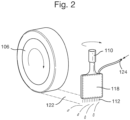
- FIG 2 shows in more detail the pyrotechnic cylinder 110 positioned in front of a wheel 106.
- the pyrotechnic cylinder 110 is connected to a deflector 118 which, as is shown in Figure 3 , defines an internal chamber that acts as a plenum to distribute gas entering from the upper end to a plurality of nozzles at the lower end, forming a gas outlet 112.
- the plenum has a convergent-divergent, or waisted, profile to provide a de Laval nozzle shape.
- a channel or conduit 124 which communicates with the vent 116 (see Figure 1 ) mentioned above.
- the nozzles forming the gas outlet 112 direct gas from the cylinder 110 so as to clear water and/or debris from the road surface in front of the wheel 106 so as to provide a dry area 122 behind the gas outlet 112 and in front of the wheel 106.
- the system shown in the Figures is provided on a four-wheeled passenger vehicle.
- four gas cylinders 110 and deflectors 118 are provided, one for each wheel 106a.b (only two of which are shown).
- the deflector 118 is close enough to the road to reduce the amount of water or other debris getting to the tyre - e.g. approximately 5mm.
- This deflector generally improves driving conditions and could be fixed or, as in this embodiment, can be deployed from a stored position to the illustrated operating position as driving conditions become worse, but before there is a need for emergency intervention.
- the deflector may be constructed from a tough and resilient rubber based material appropriate to its location.
- the deflector may also comprise a wear resistant replaceable impact strip.
- the deflector may provide a lower aerodynamic drag coefficient than the tyre itself and the overall drag force on the vehicle may thus be reduced, assisting fuel economy.
- Figure 4 shows the selective deployment of the deflector 118.
- the deflector 118 in a stored position 300 and a deployed, operating position 302.
- the deflector 118 and pyrotechnic canister 110 are positioned forward of the wheel 106.
- the deflector 118 Upon receipt of an appropriate signal from the control system, the deflector 118 can be deployed so that the gas outlet 112 is close to the road surface. A clearance of about 5 mm is envisaged as mentioned earlier.
- sensors 114 In use information is provided from sensors 114 to a vehicle control system to control the operation of the deflectors 118 and gas sources 110.
- the sensors 114 can scan the road ahead to provide critical operational information describing the oncoming road conditions.
- Information can also be obtained from wheel rotation sensors which can, for example, determine if one or more wheels has lost grip of the road surface. This information is then provided to an on-board computer system controlling operation of the system as is described further below.
- the deflector 118 In benign driving conditions the deflector 118 will be in the stored position 300; whereas, if weather conditions deteriorate the deflector 118 can be deployed to the operating position 302. When deployed the deflector 118 is close enough to the road to reduce the amount of water and /or other debris getting to the tyre.
- the air entering the deflector 118 from the vents 116 via the channel 124 can provide a steady flow which is able to lift and move surface water from the road in front of the tyres albeit that it has relatively low momentum. Additional air can come from multiple sources that include conventional air vents, electric motors (where fitted to electric vehicles or hybrid electric vehicles) etc.
- a signal is generated by the vehicle control system and is sent to the pyrotechnic cylinder 110.
- the cylinder 110 activates and expels a rapid burst of hot gas through the nozzle interior chamber of the deflector 118 which has a waisted section to form a de Laval nozzle.
- This nozzle is designed to accelerate the hot gas towards the gas outlet 112.
- the hot gas is then able to lift and or move the surface water 120 from the road providing a dry section of road 122 for the tyre to move along.
- the deflector 118 is already in its operating position when the above-mentioned signal is triggered. However if it is not, the deployment mechanism is arranged to permit forceful deployment under the force of the explosive gases from the cylinder 110.
- Figure 5A shows a front view of the vehicle 400 of another embodiment on a road surface 104. Also shown are the two front wheels 406a, 406c. An arrow 410 shows the direction in which water and/or debris cleared from the road surface is moved. The arrow 410 is directed towards the side of the vehicle 400.
- Figure 5B shows a top view of the vehicle 400 also showing the front wheels 406a, c.
- a deflector 402 In front of each wheel 406a,c is a deflector 402 and a deflector mounting 404.
- the deflector 402 can be rotated about the mounting 404 in order to clear water and/ or debris from the road surface in the direction of the arrow 410 towards the side of the road 408.
- the control system may use information from sensors on the vehicle to set the angle of rotation of the deflector 402 about the deflector mounting 404 to provide the most optimal performance.
- the deflectors 402 can be adjusted and rotated to push the surface water and/or debris to the left or the right of the vehicle depending on the side of the road used for driving in the country of operation.
- the deflector may have a single inclined surface for deflecting water and / or debris to one side.
- asymmetric deflectors can be adjusted to the change in driving.
Landscapes
- Engineering & Computer Science (AREA)
- Mechanical Engineering (AREA)
- Automation & Control Theory (AREA)
- Traffic Control Systems (AREA)
- Tires In General (AREA)
- Control Of Driving Devices And Active Controlling Of Vehicle (AREA)
Description
- The present disclosure relates to apparatus for improving traction for vehicles travelling in wet or otherwise slippery conditions.
- The opportunity to provide vehicle tyres with an improved or dry road surface offers a significant opportunity to improve future vehicle safety. The forces generated in a tyre contact patch that control traction, braking and cornering are greatly compromised by road surface contamination which in most areas of the world is predominantly in the form of surface water during or following rain.
- In Europe a significant number of accidents are weather related, and in order to support EU targets, e.g. move close to zero fatalities by 2050 (European Commission, White paper on transport, 2011). Adverse weather conditions involving reduced traction as a consequence of wet, snowy and icy surfaces have been major contributory factors to traffic accidents in Europe. Extreme weather conditions are responsible for 39% of all traffic accidents in Germany. On Swedish roads 25% of accidents occur on wet roads, 16% on icy/snowy roads (Ditze, M. et al., 2010, A Survey on Intelligent Vehicle Safety Systems for Adverse Weather Conditions. FISITA, Budapest, 2010). The problem is not just restricted to Europe. In the USA on average, 6,250 people are killed and over 480,000 people are injured in weather-related crashes each year. (Source: Ten-year averages from 2002 to 2012 analyzed by Booz Allen Hamilton, based on NHTSA data http://www.ops.fhwa.dot.gov/weather/q1 roadimpact.htm ).
- The ambition to reduce accidents and fatalities is further challenged by evidence that global warming is leading to more regular occurrences of heavy rainfall as evidenced by a recent UK Met Office report that includes the following key quotes: "There is an increasing body of evidence that extreme daily rainfall rates are becoming more intense, and that the rate of increase is consistent with what is expected from fundamental physics". "There is no evidence to counter the basic premise that a warmer world will lead to more intense daily and hourly heavy rain events". (Slingo, J. et al., 2014. The Recent Storms and Floods in the UK. Met Office and Centre for Ecology & Hydrology Report Feb 2014, 27pp .).
- These weather patterns, that may include short very intense periods of rainfall, are particularly dangerous as visibility is impaired and standing surface water can build up rapidly on the road surface. Accidents in severe weather arise mainly due to a drastic loss of friction between the tyres and the road surface. Aquaplaning, sometimes referred to as hydroplaning, occurs when a layer of surface water builds up between the tyre and the road surface leading to a complete loss of grip. Aquaplaning is extremely dangerous and can occur at speeds of 50 mph (80 km/h) with as little as 2 to 3mm of standing water. The loss of visibility in heavy rain combined with spray and splash, loss of visibility in snow or even the conditions of driving in high winds can add stress to the driving task and contribute to a loss of control. A common factor in accidents when road surface friction is reduced is how quickly total loss of control occurs. This presents a problem for even the most skilled drivers to regain control in such a short time. In good conditions where the road is dry and the tyres are in good condition the coefficient of friction between the tyre contact patch and the road surface is about 1.0. When the roads are wet, and depending on tyre condition, this can be reduced to about 0.5, effectively a 50% loss in grip. This decrease in the coefficient of friction is demonstrated by the increased braking distance on wet roads. According to the UK Highway code stopping distances approximately double on wet roads. Although the tread design of modern tyres is highly advanced and assists in moving surface water away from the tyre contact patch, serious conditions that lead to aquaplaning still occur.
- With modern tyres there exists a compromise between grip and fuel efficiency. The fuel used to propel our vehicles is expended overcoming parasitic losses such as aerodynamic drag, mechanical losses in the powertrain and accelerating the vehicle mass. A fourth parasitic loss exists in the form of tyre rolling resistance which accounts for approximately 20% of all fuel used by the vehicle, 1 tank in 5, while driving. These losses occur due to the mechanical and material design of the tyre and the operational need for the tyre to present a significant contact area to the road surface resulting in continuing deformation of the tyre structure as it rolls into, through and out of the contact patch area. Designing tyres to be more fuel efficient is constrained by the need to provide grip, particularly on low friction surfaces such as those occurring in the wet.
-
EP 0512264 ,WO 2011/102775 ,US 4063606 ,DE 102010053308 , and -
DE 100118906 all describe nozzle based systems configured to project a single jet of air in front of a tyre wherein the nozzle is located close to the road surface. -
US3544370 describes the combined use of a deflector and a nozzle for supplying gas to a road surface. - The present disclosure aims to provide a system, external to the tyre, which provides an opportunity to reduce the effect of wet road surfaces and can offer opportunities to remove some constraints in tyre design and to pursue further reductions in tyre rolling resistance.
- When viewed from a first aspect the present invention provides apparatus on a wheeled vehicle as claimed in claim 1.
- When viewed from another aspect the invention provides apparatus for a wheeled vehicle as claimed in claim 15.
- Thus it will be seen by those skilled in the art that in accordance with the invention a gas source is able to supply a burst of gas which can move and / or lift surface water and other debris from the road. The opportunity to provide a dry road surface in front of tyres offers a significant improvement to vehicle safety. The forces generated in a tyre contact patch control traction, braking and cornering. These forces are greatly compromised by road surface contamination, which is mostly in the form of surface water following rain. In serious weather conditions aquaplaning can still occur, despite the advanced tread design of modern tyres. A dry road surface in front of a tyre will limit the possibility of aquaplaning. Furthermore, when the frictional contact with the road is reduced, braking distances are adversely affected. Providing a dry road surface in front of the tyre will reduce braking distance, thus enhancing safety. This is particularly important in the event of emergency braking. The burst of gas could therefore be deployed when anti-lock brakes are employed for example. The system may also assist in preventing loss of control on snow, slush, mud etc.
- The gas source comprises exhaust gases from a pyrotechnic explosion. A pyrotechnic explosion provides hot gases at very high velocity. This will happen for a short duration but the Applicant has appreciated that this can be sufficient to assist the safe retrieval of vehicle control. A pyrotechnic explosion can be also be quickly activated. Pyrotechnics are already used safely in vehicles, for example to control the firing of airbags or the deployment of pedestrian friendly bonnets. Optionally the gas source is single use and can be easily replaced after use.
- In some embodiments the vehicle comprises one or more further gas outlets arranged to direct a, or the, burst of gas so as to clear water and/or debris from the road surface in front of all of the wheels which are directly driven. Additional gas outlets may be arranged to direct a, or the, burst of gas so as to clear water and/or debris from the road surface in front of any non-driven wheels. For example, for a motor cycle a gas outlet may be provided for the front and the real wheel. For a three-wheeled vehicle, the gas source may be provided in front of the two laterally spaced wheels at the front or rear, or for all three wheels. For vehicles with a greater number of wheels, a gas outlet may be provided at least in front of all the wheels which are used for steering, and may be provided for all or a selection of the other wheels, as deemed necessary.
- Preferably, the gas outlet, or each of the outlets, is disposed closely adjacent to the road surface - e.g. spaced by less than 5 cm, e.g. less than 2 cm, e.g. less than 1cm - enabling more effective removal of surface water and / or debris.
- In some embodiments, the vehicle comprises a further gas source. This could be used simply to enhance the burst of gas, but preferably it allows for removal of water or other road surface contaminants over a longer period of time than the burst of gas described above. This may provide an improvement in friction between the tyre and the road in circumstances which do not call for the emergency deployment of the burst of gas.
- The further gas source may be provided by any of a number of methods, e.g. a compressed air cylinder, air extracted from cooling fans or from a compressor. In a set of embodiments however the further gas source comprises a vent arranged to draw in ambient air. For example, air could be diverted from the vents presently provided on some vehicles for air cooling of brakes. Preferably however one or more dedicated vents is provided.
- It is envisaged that the additional gas source will supply air, although it could be another gas, such as nitrogen, or be air mixed with another gas.
- As mentioned above it is beneficial for the gas outlet to be as close to the road surface as possible. On the other hand, it is important to avoid the gas outlet striking the surface of the road if the surface is uneven for example. In a set of embodiments the or each gas outlet is therefore arranged on a mounting so as to be movable towards and away from the road surface. This allows the gas outlet to be deployed only when required or likely to be required. The mounting could, for example, be controlled by the control system. Where the vehicle has a plurality of gas sources they may move in unison, or may move individually.
- The outlet may be deployed from its stored position using a small motor, a spring, a suspension component, or pneumatic or hydraulic actuator. The outlet could be attached to the wheel knuckle in order to maintain control of its height above the road surface as attaching the device to the vehicle body would result in road impacts as the body bounces and pitches on the vehicle suspension. A load cell could also be included in the deployment mechanism to provide optimal height control depending on the road conditions such as surface water, snow or slush.
- When the gas outlet is in its stored position it is typically protected from impact with the road surface and does not contribute to the air resistance of the vehicle. In the situation where the weather is not severe and the gas outlet is in a stored position but loss of friction and control is suddenly detected, the gas outlet and source can advantageously be deployed as rapidly as possible from the stored position to the emergency operating position. In a set of embodiments the gas source, e.g. the pyrotechnic exhaust gases, could provide enough energy to deploy the gas outlet from its stored to its operating position, i.e. so as to over-ride any mounting or movement system and provide the thrust on initial firing to operate the mechanism and move the gas outlet rapidly into the operating position close to the road.
- In some embodiments the gas outlet comprises a nozzle. Additionally or alternatively the gas outlet comprises a valve configured to accelerate gas. The valve configured to accelerate gas may be, for example, a convergent-divergent nozzle, such as a de Laval nozzle. A de Laval nozzle is able to accelerate a hot, pressurised gas to a high speed in the axial (thrust) direction, by converting the heat energy of the flow into kinetic energy. Increasing the velocity of the gas improves the response time of the system and increases the momentum of the gas. High momentum gas is able to clear a larger area of road as it is able to displace a larger volume of water.
- In some embodiments, the control system comprises an on-board camera, laser, tyre based sensors or rain sensors. Many of these sensors already exist in vehicles. For example, rain sensors inform the operation of windscreen wiper systems and traction control systems utilise information from wheel sensors.
- Such a control system may also be informed by data from Vehicle-to-Vehicle (V2V) and Vehicle-to-Infrastructure (V2I) communication systems. Examples of control systems on modern vehicles are Advanced Driver Assistance Systems such as Lane Keeping and Adaptive Cruise Control. Active safety systems such as Emergency Braking Assistance and next generation systems for providing Road Departure Prevention may also be used. These systems will increasingly use other information protocols external to the vehicle to gather data such as V2V or V2I. This means for example that a vehicle travelling several hundred metres in front in a country lane could provide information on say pooled surface water which would inform the operation of a system of the kind described herein. Future V2I systems may also include road profiling information regarding bumps and potholes for example. While these systems may be used to provide information for active suspension systems and magneto-rheological dampers, the information could also be used to inform the operation of a system in accordance with the present invention. It is therefore intended that the data captured to inform the operation of the system can be obtained from sensors already installed to support existing and next generation vehicle safety systems.
- In a set of embodiments the vehicle further comprises a deflector configured to deflect water and/or debris from said road surface in a vicinity of said wheel. In a set of such embodiments the deflector comprises a single laterally directed surface. The deflector may be deployed in front of the tyre, close enough to the road to reduce the amount of water and / or other debris getting to the tyre in order generally to improve driving conditions. As described above for the gas outlet, it may be spaced e.g. by less than 5 cm, e.g. less than 2 cm, e.g. less than 1cm.
- The deflector is advantageously made from a durable material appropriate to its location and exposure to a harsh environment. For example, a rubber-like material similar to that used in the manufacture of mud flaps could be used. Should excessive wear occur over time, the lower section of the deflector, where the most wear occurs, may be designed as an inexpensive replaceable service item.
- In a set of embodiments a position of the deflector relative to the road surface can be controlled. For example in non-severe weather conditions the deflector could be stored away from the road surface. It is thus envisaged that the deflector could be movable both towards and away from the road surface. As described above for the gas outlet, the deflector could be attached to the vehicle via a small motor, a spring, a hydraulic or a mechanic actuator. A load cell could also be included in the deployment mechanism to provide optimal height control depending on the road surface conditions.
- In a set of embodiments the deflector is rotatable about a substantially vertical axis. The deflector can then be set at an angle to move water and / or debris in a certain direction. Thus, for example, if there are two laterally spaced wheels on the vehicle, the deflectors may deflect the water to both sides of the vehicle, or to one side of the vehicle. Conveniently a computer based control of the device - such as the aforementioned control system - will use information from sensors to set the angle of the deflector in a plan view to provide the most optimal performance.
- If, during severe weather and heavy traffic, the majority of vehicles are fitted with deflectors of the kind described and they are all deployed, the vehicles may effectively "sweep" water snow or slush away from the road. In this way overall road conditions may be improved and all road users also may be exposed to less spray and have better visibility.
- While the above described system is primarily aimed at the removal of surface water, the system could easily be designed to cope with soft snow, slush, sand or other friction compromising materials such as wet leaves or mud.
- The arrangements described herein could be used for all road vehicles, including cars, buses, trucks, and motorcycles, but could also be used on non-road vehicles, for example agricultural machinery, aircraft, and trains.
- One or more non-limiting examples will now be described with reference to the accompanying drawings, in which:
-
Figure 1 shows a vehicle in accordance with an embodiment of the invention; -
Figure 2 shows part of the embodiment ofFigure 1 including a gas source, a gas outlet and deflector positioned in front of a wheel; -
Figure 3 shows a cross section of the gas source and deflector ofFigure 2 ; -
Figure 4 shows the movement of the components ofFigures 2 and3 relative to the wheel; and -
Figures 5A and 5B show front and top views respectively of another embodiment providing movement of water and/or debris to the side of the road. -
Figure 1 shows a side view of avehicle 100 embodying the invention moving in the direction of thearrow 102 along aroad surface 104. The Figure shows one of thefront wheels 106a and one of therear wheels 106b. Thewheels 106a,b contact theroad surface 104 overrespective contact patches 108. Mounted to the vehicle chassis in front of eachwheel 106a,b is a gas source 110 - in this case a pyrotechnic gas cylinder - and agas outlet 112 which are described in greater detail hereinbelow. Thepyrotechnic gas cylinder 110 is single use, removable and replaceable. - The vehicle also has a number of sensors forming part of a typical vehicle monitoring system, represented schematically by an on-board-
camera 114. Such a system, may typically include a large number of sensors such as temperature sensors, wheel monitoring sensors etc., - An additional gas source is provided by
vents 116 in the vehicle's body which are designed to draw in ambient air as the vehicle is travelling. - A
deflector 118 is positioned in front of eachwheel 106a,b.Figure 1 also shows diagrammatically a layer of water and/ordebris 120 on the road surface. -
Figure 2 shows in more detail thepyrotechnic cylinder 110 positioned in front of awheel 106. Thepyrotechnic cylinder 110 is connected to adeflector 118 which, as is shown inFigure 3 , defines an internal chamber that acts as a plenum to distribute gas entering from the upper end to a plurality of nozzles at the lower end, forming agas outlet 112. The plenum has a convergent-divergent, or waisted, profile to provide a de Laval nozzle shape. - Also connected to the internal chamber is a channel or
conduit 124 which communicates with the vent 116 (seeFigure 1 ) mentioned above. The nozzles forming thegas outlet 112 direct gas from thecylinder 110 so as to clear water and/or debris from the road surface in front of thewheel 106 so as to provide adry area 122 behind thegas outlet 112 and in front of thewheel 106. - The system shown in the Figures is provided on a four-wheeled passenger vehicle. In this embodiment four
gas cylinders 110 anddeflectors 118 are provided, one for each wheel 106a.b (only two of which are shown). - The
deflector 118 is close enough to the road to reduce the amount of water or other debris getting to the tyre - e.g. approximately 5mm. This deflector generally improves driving conditions and could be fixed or, as in this embodiment, can be deployed from a stored position to the illustrated operating position as driving conditions become worse, but before there is a need for emergency intervention. - The deflector may be constructed from a tough and resilient rubber based material appropriate to its location. The deflector may also comprise a wear resistant replaceable impact strip.
- The deflector may provide a lower aerodynamic drag coefficient than the tyre itself and the overall drag force on the vehicle may thus be reduced, assisting fuel economy.
-
Figure 4 shows the selective deployment of thedeflector 118. In particular it shows thedeflector 118 in a storedposition 300 and a deployed, operatingposition 302. In both the stored and deployedpositions deflector 118 andpyrotechnic canister 110 are positioned forward of thewheel 106. - Upon receipt of an appropriate signal from the control system, the
deflector 118 can be deployed so that thegas outlet 112 is close to the road surface. A clearance of about 5 mm is envisaged as mentioned earlier. - In use information is provided from
sensors 114 to a vehicle control system to control the operation of thedeflectors 118 andgas sources 110. Thesensors 114 can scan the road ahead to provide critical operational information describing the oncoming road conditions. Information can also be obtained from wheel rotation sensors which can, for example, determine if one or more wheels has lost grip of the road surface. This information is then provided to an on-board computer system controlling operation of the system as is described further below. - In benign driving conditions the
deflector 118 will be in the storedposition 300; whereas, if weather conditions deteriorate thedeflector 118 can be deployed to theoperating position 302. When deployed thedeflector 118 is close enough to the road to reduce the amount of water and /or other debris getting to the tyre. The air entering thedeflector 118 from thevents 116 via thechannel 124 can provide a steady flow which is able to lift and move surface water from the road in front of the tyres albeit that it has relatively low momentum. Additional air can come from multiple sources that include conventional air vents, electric motors (where fitted to electric vehicles or hybrid electric vehicles) etc. - In the event of an emergency where the vehicle has lost frictional contact with the road, or is in imminent danger of doing so, a signal is generated by the vehicle control system and is sent to the
pyrotechnic cylinder 110. Upon receiving this thecylinder 110 activates and expels a rapid burst of hot gas through the nozzle interior chamber of thedeflector 118 which has a waisted section to form a de Laval nozzle. This nozzle is designed to accelerate the hot gas towards thegas outlet 112. The hot gas is then able to lift and or move thesurface water 120 from the road providing a dry section ofroad 122 for the tyre to move along. Ideally thedeflector 118 is already in its operating position when the above-mentioned signal is triggered. However if it is not, the deployment mechanism is arranged to permit forceful deployment under the force of the explosive gases from thecylinder 110. - Another embodiment will now be described with reference to
Figs. 5A and 5B . This is very similar to the previous embodiment except that the deflectors can be adjusted. -
Figure 5A shows a front view of thevehicle 400 of another embodiment on aroad surface 104. Also shown are the twofront wheels arrow 410 shows the direction in which water and/or debris cleared from the road surface is moved. Thearrow 410 is directed towards the side of thevehicle 400. -
Figure 5B shows a top view of thevehicle 400 also showing thefront wheels 406a, c. In front of eachwheel 406a,c is adeflector 402 and a deflector mounting 404. In this embodiment thedeflector 402 can be rotated about the mounting 404 in order to clear water and/ or debris from the road surface in the direction of thearrow 410 towards the side of theroad 408. The control system may use information from sensors on the vehicle to set the angle of rotation of thedeflector 402 about the deflector mounting 404 to provide the most optimal performance. - The
deflectors 402 can be adjusted and rotated to push the surface water and/or debris to the left or the right of the vehicle depending on the side of the road used for driving in the country of operation. The deflector may have a single inclined surface for deflecting water and / or debris to one side. For vehicles moving from country to country, asymmetric deflectors can be adjusted to the change in driving. - During severe weather and heavy traffic, if the majority of vehicles are fitted with
such deflectors 402 the vehicles may effectively "sweep" water and/or debris away from the road. In this way overall road conditions may be improved for all road users who will also be exposed to less spray and have better visibility. - The development and optimisation of the system can be achieved through the use of advanced computer simulations, wind tunnel studies and ground testing. These methods can optimise the shape of the deflector and the optimal position to provide the desired "sweeping" effect.
- Many variations and modifications of the arrangements described above may be made within the scope of the invention as defined in the attached claims.
Claims (15)
- Apparatus for a wheeled vehicle (100) comprising:a control system arranged to issue a signal in the event of determining that one or more wheels (106) of the vehicle has lost, or is at risk of losing, frictional contact with a road surface (104);a gas source (110) arranged to supply a burst of gas upon said signal being issued;and at least one gas outlet (112) connected to said gas source and arrangeable to direct said burst of gas so as to clear water and/or debris (120) from the road surface in front of at least one of the wheels, characterised in that the gas source comprises exhaust gasses from a pyrotechnic explosion.
- The apparatus according to claim 1, comprising one or more further gas outlets (112) arrangeable to direct a or the burst of gas so as to clear water and/or debris (120) from the road surface (104) in front of all of the wheels (106) which are directly driven.
- The apparatus according to any preceding claim, wherein the at least one gas outlet (112) is arranged on a mounting so as to be movable towards and away from the road surface (104).
- The apparatus as claimed in claim 3 wherein said mounting is controlled by the control system.
- The apparatus according to any preceding claim wherein the at least one gas source (110) is single use and replaceable.
- The apparatus according to any preceding claim, comprising a further gas source (116) arranged to supply gas to said at least one gas outlet (112) arrangeable to direct said gas so as to clear water and/or debris (120) from the road surface (104) in front of said wheel (106), optionally wherein said further gas source comprises an air intake to be located on the vehicle.
- The apparatus according to any preceding claim, wherein the at least one gas outlet (112) comprises a nozzle.
- The apparatus according to any preceding claim, wherein the at least one gas outlet (112) comprises a valve configured to accelerate gas.
- The apparatus according to any preceding claim, wherein the at least one gas outlet (112) comprises a de Laval nozzle.
- The apparatus according to any preceding claim, wherein the control system comprises an on-board camera, laser, tyre based sensor or rain sensor (114).
- The apparatus according to any preceding claim, wherein the control system is able to be informed by data from Vehicle-to Vehicle (V2V) and Vehicle-to-Infrastructure (V2I) communication systems.
- The apparatus according to any preceding claim, further comprising a deflector (118) configured to deflect water and/or debris (120) from said road surface (104).
- The apparatus according to claim 12, wherein the at least one gas outlet (112) is attached to or integrated with the deflector (118), and/or wherein the deflector is movable automatically towards and away from the road surface.
- The apparatus according to claim 12 or claim 13, wherein the deflector (118) is rotatable about a substantially vertical axis.
- Apparatus for a wheeled vehicle (100) comprising a control system arranged to issue a signal in the event of determining that one or more wheels (106) of the vehicle has lost, or is at risk of losing, frictional contact with a road surface (104), the apparatus comprising:a gas source (110) arranged to supply a burst of gas upon receiving said signal; andat least one gas outlet (112) connected to said gas source and arranged to direct said burst of gas so as to clear water and/or debris (120) from the road surface in front of at least one of the wheels, characterised in that the gas source comprises exhaust gasses from a pyrotechnic explosion.
Applications Claiming Priority (3)
| Application Number | Priority Date | Filing Date | Title |
|---|---|---|---|
| GBGB1613121.1A GB201613121D0 (en) | 2016-07-29 | 2016-07-29 | Vehicle traction enhancement |
| GBGB1616543.3A GB201616543D0 (en) | 2016-07-29 | 2016-09-29 | Vehicle traction enhancement |
| PCT/GB2017/052148 WO2018020220A1 (en) | 2016-07-29 | 2017-07-21 | Vehicle traction enhancement |
Publications (3)
| Publication Number | Publication Date |
|---|---|
| EP3490810A1 EP3490810A1 (en) | 2019-06-05 |
| EP3490810C0 EP3490810C0 (en) | 2023-06-28 |
| EP3490810B1 true EP3490810B1 (en) | 2023-06-28 |
Family
ID=56936690
Family Applications (1)
| Application Number | Title | Priority Date | Filing Date |
|---|---|---|---|
| EP17745861.9A Active EP3490810B1 (en) | 2016-07-29 | 2017-07-21 | Vehicle traction enhancement |
Country Status (7)
| Country | Link |
|---|---|
| US (1) | US11084325B2 (en) |
| EP (1) | EP3490810B1 (en) |
| JP (1) | JP6913739B2 (en) |
| CN (1) | CN109982860A (en) |
| ES (1) | ES2958626T3 (en) |
| GB (2) | GB201613121D0 (en) |
| WO (1) | WO2018020220A1 (en) |
Families Citing this family (5)
| Publication number | Priority date | Publication date | Assignee | Title |
|---|---|---|---|---|
| FR3115598A1 (en) * | 2020-10-26 | 2022-04-29 | Dryside | Optical adhesion optimization device |
| IT202100011108A1 (en) * | 2021-04-30 | 2022-10-30 | Easy Rain I S P A | ANTI-AQUAPLANING SYSTEM FOR VEHICLES AND RELATED PROCEDURE |
| CN114368249B (en) * | 2021-12-06 | 2024-07-26 | 深圳优地科技有限公司 | Robot moving method, robot and computer storage medium |
| US20240400006A1 (en) * | 2023-05-31 | 2024-12-05 | Ford Global Technologies, Llc | System for mitigation of wheel debris packing |
| CN119058601B (en) * | 2024-09-27 | 2026-03-10 | 安徽江淮汽车集团股份有限公司 | Device for improving control performance of wet road surface of vehicle |
Family Cites Families (49)
| Publication number | Priority date | Publication date | Assignee | Title |
|---|---|---|---|---|
| US3289668A (en) * | 1964-02-11 | 1966-12-06 | Drucker Siegfried | Snow and ice melting and traction device for vehicles |
| US3544370A (en) * | 1967-11-29 | 1970-12-01 | Kenneth W Wrede | Antihydroplaning method for vehicles |
| FR2119817B1 (en) * | 1970-11-10 | 1973-11-23 | Bertin & Cie | |
| DE2534722A1 (en) * | 1975-08-04 | 1977-02-17 | Geb Wefing Waltraud Nocke | Vehicle anti aquaplaning air jets - have movable nozzles in front of wheels and linked to central compressed air supply |
| DE2555282A1 (en) | 1975-12-09 | 1977-06-16 | Max Jacobs | Aquaplaning preventor for car wheel - with fan assisted ram funnel to blow air onto road in front of tyre |
| DE2600787A1 (en) * | 1976-01-10 | 1977-07-14 | Walter Dipl Ing Kustermann | Road water film deflecting mechanism - has adjustable air jet and deflector vane fitted in front of vehicle tyres |
| US4063606A (en) | 1976-09-13 | 1977-12-20 | Makinson Ruth G | Anti-hydroplaning device |
| JPS5747504Y2 (en) * | 1976-12-20 | 1982-10-19 | ||
| US4680345A (en) | 1985-06-05 | 1987-07-14 | Toyo Boseki Kabushiki Kaisha | Continuous production of elastic polyesters |
| US5100175A (en) * | 1990-11-29 | 1992-03-31 | Swallow Carl L | Tire traction enhancing kit |
| DE4115367C2 (en) | 1991-05-10 | 1994-04-21 | Deutsche Aerospace | Anti-aquaplaning system for a motor vehicle |
| JPH05229461A (en) * | 1992-02-19 | 1993-09-07 | Hitachi Ltd | Vehicle having road surface / tire friction coefficient control means |
| JPH07279138A (en) * | 1994-04-07 | 1995-10-24 | Yoshio Takahashi | Road-covering snow melting device for automobile |
| JPH07304303A (en) * | 1994-05-11 | 1995-11-21 | Shigeo Kashiwatani | Device for removing rain water between tire and road |
| US5555594A (en) * | 1994-09-23 | 1996-09-17 | Maddalena; Jack | Water and debris deflector and vacuum |
| JPH0948204A (en) * | 1995-08-07 | 1997-02-18 | Calsonic Corp | Hydroplanting preventing device |
| JPH09164804A (en) * | 1995-12-19 | 1997-06-24 | Masahiko Yamamoto | Hydroplane preventing device and automobile therewith |
| JPH09188103A (en) * | 1996-01-10 | 1997-07-22 | Sumitomo Rubber Ind Ltd | Vehicle |
| DE29716940U1 (en) | 1997-09-20 | 1998-01-08 | Hergoeth, Stefan, 89584 Ehingen | Air guidance system for vehicles of all kinds |
| US6371532B1 (en) * | 1999-01-22 | 2002-04-16 | James B. Skarie | Traction-enhancing system for use with motor vehicles |
| JP2000264009A (en) * | 1999-03-16 | 2000-09-26 | Sumitomo Rubber Ind Ltd | Vehicle |
| DE10018906A1 (en) | 2000-04-15 | 2001-10-18 | Fritz Heilmayer | Device for preventing occurrence of aquaplaning on vehicles in wet weather has air jets installed in front of wheels to direct pressurized air onto water film and disperse it |
| JP2004130851A (en) * | 2002-10-08 | 2004-04-30 | Advics:Kk | Antislip device for hybrid-type vehicle |
| JP2004130847A (en) * | 2002-10-08 | 2004-04-30 | Advics:Kk | Slip preventing device for vehicle |
| JP4389244B2 (en) * | 2003-06-19 | 2009-12-24 | 健太郎 潮田 | Vehicle contact surface frictional force improving device |
| JP2005014781A (en) * | 2003-06-26 | 2005-01-20 | Advics:Kk | Slip prevention device for vehicle |
| US7198111B2 (en) * | 2005-03-22 | 2007-04-03 | Ford Global Technologies, Llc | Automotive vehicle with fire suppression system |
| WO2007056834A1 (en) * | 2005-11-17 | 2007-05-24 | Mario Smiljanic | Compressor device for cleaning and drying the wheel tyre tread at braking |
| US20080011526A1 (en) * | 2006-07-12 | 2008-01-17 | Grande Magnar J | Hydroplaning, reducing or eliminating device |
| WO2008111039A1 (en) * | 2007-03-14 | 2008-09-18 | Aharon Krishevski | A vehicular anti-skidding system and method |
| CN101117082A (en) * | 2007-07-23 | 2008-02-06 | 王晓炜 | Vehicle tyre jetting type water elimination device |
| ITBO20070740A1 (en) * | 2007-11-07 | 2009-05-08 | Marco Pozzi | ANTI-AQUAPLANING DEVICE AND METHOD |
| CN201176579Y (en) * | 2008-03-24 | 2009-01-07 | 湖南吉利汽车部件有限公司 | Automobile road surface freezing device |
| US8169338B2 (en) * | 2008-07-25 | 2012-05-01 | GM Global Technology Operations LLC | Inter-vehicle communication feature awareness and diagnosis system |
| US8465061B1 (en) * | 2008-11-26 | 2013-06-18 | Donald J. Reid | Traction system |
| AU2009100914A4 (en) * | 2009-09-11 | 2009-10-22 | Gerard M. A. Westenberg | Improved traction blower system |
| SE534423C2 (en) | 2010-02-19 | 2011-08-16 | Martin Eriksson | Systems and method for improved wet grip on wet road |
| DE102010053308A1 (en) | 2010-12-02 | 2011-07-28 | Daimler AG, 70327 | Method for operating vehicle, involves blowing off water surface in front of vehicle tire by air jet generated by air nozzle, where acoustic signal is detected in area of track |
| US8800177B2 (en) * | 2011-04-26 | 2014-08-12 | Steve Harrington | Pneumatic excavation system and method of use |
| ITPN20120028A1 (en) * | 2012-06-01 | 2013-12-02 | Giovanni Amos Blandina | DEVICE FOR AVOIDING THE AQUAPLANING PHENOMENON IN A VEHICLE |
| US20140081515A1 (en) * | 2012-09-14 | 2014-03-20 | Peter E. Goulet | Automotive friction assist system with improved traction |
| US9056525B2 (en) * | 2013-01-02 | 2015-06-16 | The Boeing Company | Anti-skid systems for vehicle tires on icy road conditions and method therefor |
| JP6347369B2 (en) * | 2013-03-25 | 2018-06-27 | エイディシーテクノロジー株式会社 | vehicle |
| US20160016558A1 (en) * | 2013-05-20 | 2016-01-21 | Steven James Santacroce | Debris removal system for a vehicle |
| US9440493B1 (en) * | 2013-11-04 | 2016-09-13 | Timothy J. Ahern | Traction material dispensing apparatus |
| EP3000615B1 (en) * | 2014-09-29 | 2019-12-04 | Easy Rain I.S.P.A. | A system for preventing aquaplaning in a vehicle |
| US9333995B1 (en) * | 2015-02-25 | 2016-05-10 | Matthew S. Piotrowski | Crosswind airflow countering thrust assembly and transport vehicle formed therewith |
| CN104816586B (en) * | 2015-04-28 | 2018-02-06 | 上海昊洛电子科技有限公司 | It is a kind of to improve the system of operating conditions and its application between operating body and delivery basal plane |
| CN105059275B (en) * | 2015-06-26 | 2021-06-29 | 山东顺安达汽车科技股份有限公司 | Quick braking device for wet and slippery road surface of battery car |
-
2016
- 2016-07-29 GB GBGB1613121.1A patent/GB201613121D0/en not_active Ceased
- 2016-09-29 GB GBGB1616543.3A patent/GB201616543D0/en not_active Ceased
-
2017
- 2017-07-21 ES ES17745861T patent/ES2958626T3/en active Active
- 2017-07-21 US US16/321,184 patent/US11084325B2/en active Active
- 2017-07-21 CN CN201780057902.0A patent/CN109982860A/en active Pending
- 2017-07-21 WO PCT/GB2017/052148 patent/WO2018020220A1/en not_active Ceased
- 2017-07-21 JP JP2019504706A patent/JP6913739B2/en active Active
- 2017-07-21 EP EP17745861.9A patent/EP3490810B1/en active Active
Also Published As
| Publication number | Publication date |
|---|---|
| US20190168541A1 (en) | 2019-06-06 |
| ES2958626T3 (en) | 2024-02-12 |
| WO2018020220A1 (en) | 2018-02-01 |
| GB201613121D0 (en) | 2016-09-14 |
| JP6913739B2 (en) | 2021-08-04 |
| US11084325B2 (en) | 2021-08-10 |
| EP3490810C0 (en) | 2023-06-28 |
| JP2019521909A (en) | 2019-08-08 |
| CN109982860A (en) | 2019-07-05 |
| GB201616543D0 (en) | 2016-11-16 |
| EP3490810A1 (en) | 2019-06-05 |
Similar Documents
| Publication | Publication Date | Title |
|---|---|---|
| US11084325B2 (en) | Vehicle traction enhancement | |
| US4486046A (en) | Undercarriage airstream deflector assembly for truck trailers and the like | |
| US8528936B2 (en) | Rain hazard eliminator | |
| US6099069A (en) | Device to selectively create drag on a transport vehicle for speed reduction | |
| US20170088091A1 (en) | Deployable pedestrian safety device for vehicles | |
| EP2058141B1 (en) | Anti-aquaplaning device | |
| US20140070564A1 (en) | Air flow control assembly for a motor vehicle | |
| US11110974B2 (en) | Fairing assembly for at least one axle of a commercial vehicle | |
| GB2495983A (en) | Emergency braking system for a wheeled land vehicle that changes the aerodynamic characteristics of the vehicle | |
| CN114475541A (en) | Automatic emergency braking method considering passenger safety | |
| KR20150068356A (en) | Deflector device and motor vehicle in which the front shield carries said deflector device | |
| US20140110968A1 (en) | Aerodynamic control system for trailers | |
| US11938791B1 (en) | Protective windshield system | |
| KR20220117356A (en) | Road anti-skid system on black ice (snow, rain) | |
| FI108418B (en) | Procedure and device for vehicle safety device | |
| EP0149665B1 (en) | Water spray control for vehicle wheels | |
| WO2011102775A1 (en) | System and method for improving traction on wet road surfaces | |
| WO2004078561A1 (en) | Means for redirecting tyre spray | |
| AU2023341972A1 (en) | Spray suppression device | |
| JP5346139B1 (en) | Rainy spoiler | |
| RU2104895C1 (en) | Automobile | |
| GB2443546A (en) | Water spray reduction | |
| CN2068524U (en) | Snow-scraping apparatus for automobile | |
| GB2419855A (en) | Surface water remover | |
| CN101074012A (en) | Emergent brake of automobile |
Legal Events
| Date | Code | Title | Description |
|---|---|---|---|
| STAA | Information on the status of an ep patent application or granted ep patent |
Free format text: STATUS: UNKNOWN |
|
| STAA | Information on the status of an ep patent application or granted ep patent |
Free format text: STATUS: THE INTERNATIONAL PUBLICATION HAS BEEN MADE |
|
| PUAI | Public reference made under article 153(3) epc to a published international application that has entered the european phase |
Free format text: ORIGINAL CODE: 0009012 |
|
| STAA | Information on the status of an ep patent application or granted ep patent |
Free format text: STATUS: REQUEST FOR EXAMINATION WAS MADE |
|
| 17P | Request for examination filed |
Effective date: 20190227 |
|
| AK | Designated contracting states |
Kind code of ref document: A1 Designated state(s): AL AT BE BG CH CY CZ DE DK EE ES FI FR GB GR HR HU IE IS IT LI LT LU LV MC MK MT NL NO PL PT RO RS SE SI SK SM TR |
|
| AX | Request for extension of the european patent |
Extension state: BA ME |
|
| DAV | Request for validation of the european patent (deleted) | ||
| DAX | Request for extension of the european patent (deleted) | ||
| GRAP | Despatch of communication of intention to grant a patent |
Free format text: ORIGINAL CODE: EPIDOSNIGR1 |
|
| STAA | Information on the status of an ep patent application or granted ep patent |
Free format text: STATUS: GRANT OF PATENT IS INTENDED |
|
| INTG | Intention to grant announced |
Effective date: 20220509 |
|
| GRAJ | Information related to disapproval of communication of intention to grant by the applicant or resumption of examination proceedings by the epo deleted |
Free format text: ORIGINAL CODE: EPIDOSDIGR1 |
|
| STAA | Information on the status of an ep patent application or granted ep patent |
Free format text: STATUS: REQUEST FOR EXAMINATION WAS MADE |
|
| GRAP | Despatch of communication of intention to grant a patent |
Free format text: ORIGINAL CODE: EPIDOSNIGR1 |
|
| STAA | Information on the status of an ep patent application or granted ep patent |
Free format text: STATUS: GRANT OF PATENT IS INTENDED |
|
| INTC | Intention to grant announced (deleted) | ||
| INTG | Intention to grant announced |
Effective date: 20221025 |
|
| GRAS | Grant fee paid |
Free format text: ORIGINAL CODE: EPIDOSNIGR3 |
|
| GRAA | (expected) grant |
Free format text: ORIGINAL CODE: 0009210 |
|
| STAA | Information on the status of an ep patent application or granted ep patent |
Free format text: STATUS: THE PATENT HAS BEEN GRANTED |
|
| AK | Designated contracting states |
Kind code of ref document: B1 Designated state(s): AL AT BE BG CH CY CZ DE DK EE ES FI FR GB GR HR HU IE IS IT LI LT LU LV MC MK MT NL NO PL PT RO RS SE SI SK SM TR |
|
| REG | Reference to a national code |
Ref country code: CH Ref legal event code: EP |
|
| REG | Reference to a national code |
Ref country code: AT Ref legal event code: REF Ref document number: 1582399 Country of ref document: AT Kind code of ref document: T Effective date: 20230715 |
|
| REG | Reference to a national code |
Ref country code: IE Ref legal event code: FG4D |
|
| REG | Reference to a national code |
Ref country code: DE Ref legal event code: R096 Ref document number: 602017070667 Country of ref document: DE |
|
| U01 | Request for unitary effect filed |
Effective date: 20230728 |
|
| U07 | Unitary effect registered |
Designated state(s): AT BE BG DE DK EE FI FR IT LT LU LV MT NL PT SE SI Effective date: 20230803 |
|
| REG | Reference to a national code |
Ref country code: LT Ref legal event code: MG9D |
|
| PG25 | Lapsed in a contracting state [announced via postgrant information from national office to epo] |
Ref country code: NO Free format text: LAPSE BECAUSE OF FAILURE TO SUBMIT A TRANSLATION OF THE DESCRIPTION OR TO PAY THE FEE WITHIN THE PRESCRIBED TIME-LIMIT Effective date: 20230928 |
|
| PG25 | Lapsed in a contracting state [announced via postgrant information from national office to epo] |
Ref country code: RS Free format text: LAPSE BECAUSE OF FAILURE TO SUBMIT A TRANSLATION OF THE DESCRIPTION OR TO PAY THE FEE WITHIN THE PRESCRIBED TIME-LIMIT Effective date: 20230628 Ref country code: HR Free format text: LAPSE BECAUSE OF FAILURE TO SUBMIT A TRANSLATION OF THE DESCRIPTION OR TO PAY THE FEE WITHIN THE PRESCRIBED TIME-LIMIT Effective date: 20230628 Ref country code: GR Free format text: LAPSE BECAUSE OF FAILURE TO SUBMIT A TRANSLATION OF THE DESCRIPTION OR TO PAY THE FEE WITHIN THE PRESCRIBED TIME-LIMIT Effective date: 20230929 |
|
| U20 | Renewal fee for the european patent with unitary effect paid |
Year of fee payment: 7 Effective date: 20231102 |
|
| PG25 | Lapsed in a contracting state [announced via postgrant information from national office to epo] |
Ref country code: SK Free format text: LAPSE BECAUSE OF FAILURE TO SUBMIT A TRANSLATION OF THE DESCRIPTION OR TO PAY THE FEE WITHIN THE PRESCRIBED TIME-LIMIT Effective date: 20230628 |
|
| PG25 | Lapsed in a contracting state [announced via postgrant information from national office to epo] |
Ref country code: IS Free format text: LAPSE BECAUSE OF FAILURE TO SUBMIT A TRANSLATION OF THE DESCRIPTION OR TO PAY THE FEE WITHIN THE PRESCRIBED TIME-LIMIT Effective date: 20231028 |
|
| PG25 | Lapsed in a contracting state [announced via postgrant information from national office to epo] |
Ref country code: SM Free format text: LAPSE BECAUSE OF FAILURE TO SUBMIT A TRANSLATION OF THE DESCRIPTION OR TO PAY THE FEE WITHIN THE PRESCRIBED TIME-LIMIT Effective date: 20230628 Ref country code: SK Free format text: LAPSE BECAUSE OF FAILURE TO SUBMIT A TRANSLATION OF THE DESCRIPTION OR TO PAY THE FEE WITHIN THE PRESCRIBED TIME-LIMIT Effective date: 20230628 Ref country code: RO Free format text: LAPSE BECAUSE OF FAILURE TO SUBMIT A TRANSLATION OF THE DESCRIPTION OR TO PAY THE FEE WITHIN THE PRESCRIBED TIME-LIMIT Effective date: 20230628 Ref country code: IS Free format text: LAPSE BECAUSE OF FAILURE TO SUBMIT A TRANSLATION OF THE DESCRIPTION OR TO PAY THE FEE WITHIN THE PRESCRIBED TIME-LIMIT Effective date: 20231028 Ref country code: CZ Free format text: LAPSE BECAUSE OF FAILURE TO SUBMIT A TRANSLATION OF THE DESCRIPTION OR TO PAY THE FEE WITHIN THE PRESCRIBED TIME-LIMIT Effective date: 20230628 |
|
| REG | Reference to a national code |
Ref country code: ES Ref legal event code: FG2A Ref document number: 2958626 Country of ref document: ES Kind code of ref document: T3 Effective date: 20240212 |
|
| PG25 | Lapsed in a contracting state [announced via postgrant information from national office to epo] |
Ref country code: PL Free format text: LAPSE BECAUSE OF FAILURE TO SUBMIT A TRANSLATION OF THE DESCRIPTION OR TO PAY THE FEE WITHIN THE PRESCRIBED TIME-LIMIT Effective date: 20230628 |
|
| REG | Reference to a national code |
Ref country code: CH Ref legal event code: PL |
|
| PG25 | Lapsed in a contracting state [announced via postgrant information from national office to epo] |
Ref country code: MC Free format text: LAPSE BECAUSE OF FAILURE TO SUBMIT A TRANSLATION OF THE DESCRIPTION OR TO PAY THE FEE WITHIN THE PRESCRIBED TIME-LIMIT Effective date: 20230628 |
|
| PG25 | Lapsed in a contracting state [announced via postgrant information from national office to epo] |
Ref country code: MC Free format text: LAPSE BECAUSE OF FAILURE TO SUBMIT A TRANSLATION OF THE DESCRIPTION OR TO PAY THE FEE WITHIN THE PRESCRIBED TIME-LIMIT Effective date: 20230628 |
|
| REG | Reference to a national code |
Ref country code: DE Ref legal event code: R097 Ref document number: 602017070667 Country of ref document: DE |
|
| U1N | Appointed representative for the unitary patent procedure changed after the registration of the unitary effect |
Representative=s name: WILSON GUNN; GB |
|
| REG | Reference to a national code |
Ref country code: IE Ref legal event code: MM4A |
|
| PG25 | Lapsed in a contracting state [announced via postgrant information from national office to epo] |
Ref country code: CH Free format text: LAPSE BECAUSE OF NON-PAYMENT OF DUE FEES Effective date: 20230731 |
|
| PLBE | No opposition filed within time limit |
Free format text: ORIGINAL CODE: 0009261 |
|
| STAA | Information on the status of an ep patent application or granted ep patent |
Free format text: STATUS: NO OPPOSITION FILED WITHIN TIME LIMIT |
|
| 26N | No opposition filed |
Effective date: 20240402 |
|
| PG25 | Lapsed in a contracting state [announced via postgrant information from national office to epo] |
Ref country code: IE Free format text: LAPSE BECAUSE OF NON-PAYMENT OF DUE FEES Effective date: 20230721 |
|
| PG25 | Lapsed in a contracting state [announced via postgrant information from national office to epo] |
Ref country code: IE Free format text: LAPSE BECAUSE OF NON-PAYMENT OF DUE FEES Effective date: 20230721 |
|
| U20 | Renewal fee for the european patent with unitary effect paid |
Year of fee payment: 8 Effective date: 20240722 |
|
| PG25 | Lapsed in a contracting state [announced via postgrant information from national office to epo] |
Ref country code: CY Free format text: LAPSE BECAUSE OF FAILURE TO SUBMIT A TRANSLATION OF THE DESCRIPTION OR TO PAY THE FEE WITHIN THE PRESCRIBED TIME-LIMIT; INVALID AB INITIO Effective date: 20170721 |
|
| U20 | Renewal fee for the european patent with unitary effect paid |
Year of fee payment: 9 Effective date: 20250708 |
|
| PG25 | Lapsed in a contracting state [announced via postgrant information from national office to epo] |
Ref country code: HU Free format text: LAPSE BECAUSE OF FAILURE TO SUBMIT A TRANSLATION OF THE DESCRIPTION OR TO PAY THE FEE WITHIN THE PRESCRIBED TIME-LIMIT; INVALID AB INITIO Effective date: 20170721 |
|
| PGFP | Annual fee paid to national office [announced via postgrant information from national office to epo] |
Ref country code: ES Payment date: 20250827 Year of fee payment: 9 |
|
| PGFP | Annual fee paid to national office [announced via postgrant information from national office to epo] |
Ref country code: GB Payment date: 20250708 Year of fee payment: 9 |
|
| PG25 | Lapsed in a contracting state [announced via postgrant information from national office to epo] |
Ref country code: TR Free format text: LAPSE BECAUSE OF FAILURE TO SUBMIT A TRANSLATION OF THE DESCRIPTION OR TO PAY THE FEE WITHIN THE PRESCRIBED TIME-LIMIT Effective date: 20230628 |