EP3490763B1 - Tête de rasoir comprenant un film de protection - Google Patents
Tête de rasoir comprenant un film de protection Download PDFInfo
- Publication number
- EP3490763B1 EP3490763B1 EP17749157.8A EP17749157A EP3490763B1 EP 3490763 B1 EP3490763 B1 EP 3490763B1 EP 17749157 A EP17749157 A EP 17749157A EP 3490763 B1 EP3490763 B1 EP 3490763B1
- Authority
- EP
- European Patent Office
- Prior art keywords
- masking foil
- ribbon
- blade
- shaving
- shaving cartridge
- Prior art date
- Legal status (The legal status is an assumption and is not a legal conclusion. Google has not performed a legal analysis and makes no representation as to the accuracy of the status listed.)
- Active
Links
- 239000011888 foil Substances 0.000 title claims description 157
- 230000000873 masking effect Effects 0.000 title claims description 157
- 238000005520 cutting process Methods 0.000 claims description 60
- 241000277301 Esociformes Species 0.000 claims description 9
- 239000011248 coating agent Substances 0.000 claims description 6
- 238000000576 coating method Methods 0.000 claims description 6
- 239000003242 anti bacterial agent Substances 0.000 claims description 3
- 230000001050 lubricating effect Effects 0.000 claims description 3
- 230000029663 wound healing Effects 0.000 claims description 3
- 239000000463 material Substances 0.000 description 11
- 210000004209 hair Anatomy 0.000 description 7
- 239000000314 lubricant Substances 0.000 description 7
- 229910052782 aluminium Inorganic materials 0.000 description 4
- XAGFODPZIPBFFR-UHFFFAOYSA-N aluminium Chemical compound [Al] XAGFODPZIPBFFR-UHFFFAOYSA-N 0.000 description 4
- BASFCYQUMIYNBI-UHFFFAOYSA-N platinum Chemical compound [Pt] BASFCYQUMIYNBI-UHFFFAOYSA-N 0.000 description 4
- 238000005452 bending Methods 0.000 description 3
- 238000004299 exfoliation Methods 0.000 description 3
- 230000003752 improving hair Effects 0.000 description 3
- 238000005304 joining Methods 0.000 description 3
- 238000000034 method Methods 0.000 description 3
- 229920006254 polymer film Polymers 0.000 description 3
- 230000000750 progressive effect Effects 0.000 description 3
- 229910000838 Al alloy Inorganic materials 0.000 description 2
- 230000009471 action Effects 0.000 description 2
- 230000008901 benefit Effects 0.000 description 2
- 239000002131 composite material Substances 0.000 description 2
- 230000000694 effects Effects 0.000 description 2
- PCHJSUWPFVWCPO-UHFFFAOYSA-N gold Chemical compound [Au] PCHJSUWPFVWCPO-UHFFFAOYSA-N 0.000 description 2
- 229910052737 gold Inorganic materials 0.000 description 2
- 239000010931 gold Substances 0.000 description 2
- 230000002209 hydrophobic effect Effects 0.000 description 2
- 230000007794 irritation Effects 0.000 description 2
- 229910000510 noble metal Inorganic materials 0.000 description 2
- 239000004033 plastic Substances 0.000 description 2
- 229910052697 platinum Inorganic materials 0.000 description 2
- 229920001343 polytetrafluoroethylene Polymers 0.000 description 2
- 239000004810 polytetrafluoroethylene Substances 0.000 description 2
- 230000008569 process Effects 0.000 description 2
- 230000009467 reduction Effects 0.000 description 2
- 230000000717 retained effect Effects 0.000 description 2
- 241000251730 Chondrichthyes Species 0.000 description 1
- 206010017577 Gait disturbance Diseases 0.000 description 1
- 229910045601 alloy Inorganic materials 0.000 description 1
- 239000000956 alloy Substances 0.000 description 1
- 210000003484 anatomy Anatomy 0.000 description 1
- 239000003086 colorant Substances 0.000 description 1
- 230000007797 corrosion Effects 0.000 description 1
- 238000005260 corrosion Methods 0.000 description 1
- 230000007423 decrease Effects 0.000 description 1
- 230000005489 elastic deformation Effects 0.000 description 1
- 238000009760 electrical discharge machining Methods 0.000 description 1
- 238000005323 electroforming Methods 0.000 description 1
- 239000000017 hydrogel Substances 0.000 description 1
- 230000003993 interaction Effects 0.000 description 1
- 238000003698 laser cutting Methods 0.000 description 1
- 229910052751 metal Inorganic materials 0.000 description 1
- 239000002184 metal Substances 0.000 description 1
- 150000002739 metals Chemical class 0.000 description 1
- 230000003647 oxidation Effects 0.000 description 1
- 238000007254 oxidation reaction Methods 0.000 description 1
- 238000001259 photo etching Methods 0.000 description 1
- -1 polytetrafluoroethylene Polymers 0.000 description 1
- 239000011148 porous material Substances 0.000 description 1
- 238000002360 preparation method Methods 0.000 description 1
- 230000001105 regulatory effect Effects 0.000 description 1
- 210000002374 sebum Anatomy 0.000 description 1
- 230000000087 stabilizing effect Effects 0.000 description 1
- 239000010935 stainless steel Substances 0.000 description 1
- 229910001220 stainless steel Inorganic materials 0.000 description 1
- XLYOFNOQVPJJNP-UHFFFAOYSA-N water Substances O XLYOFNOQVPJJNP-UHFFFAOYSA-N 0.000 description 1
Images


Classifications
-
- B—PERFORMING OPERATIONS; TRANSPORTING
- B26—HAND CUTTING TOOLS; CUTTING; SEVERING
- B26B—HAND-HELD CUTTING TOOLS NOT OTHERWISE PROVIDED FOR
- B26B21/00—Razors of the open or knife type; Safety razors or other shaving implements of the planing type; Hair-trimming devices involving a razor-blade; Equipment therefor
- B26B21/40—Details or accessories
- B26B21/4006—Blades or blade units with discontinuous cutting edges, e.g. wire-wrapped, notches
-
- B—PERFORMING OPERATIONS; TRANSPORTING
- B26—HAND CUTTING TOOLS; CUTTING; SEVERING
- B26B—HAND-HELD CUTTING TOOLS NOT OTHERWISE PROVIDED FOR
- B26B21/00—Razors of the open or knife type; Safety razors or other shaving implements of the planing type; Hair-trimming devices involving a razor-blade; Equipment therefor
- B26B21/40—Details or accessories
- B26B21/4037—Details or parts covering the blades, e.g. caps for storage; Attachments
-
- B—PERFORMING OPERATIONS; TRANSPORTING
- B26—HAND CUTTING TOOLS; CUTTING; SEVERING
- B26B—HAND-HELD CUTTING TOOLS NOT OTHERWISE PROVIDED FOR
- B26B21/00—Razors of the open or knife type; Safety razors or other shaving implements of the planing type; Hair-trimming devices involving a razor-blade; Equipment therefor
- B26B21/40—Details or accessories
- B26B21/4068—Mounting devices; Manufacture of razors or cartridges
-
- B—PERFORMING OPERATIONS; TRANSPORTING
- B26—HAND CUTTING TOOLS; CUTTING; SEVERING
- B26B—HAND-HELD CUTTING TOOLS NOT OTHERWISE PROVIDED FOR
- B26B21/00—Razors of the open or knife type; Safety razors or other shaving implements of the planing type; Hair-trimming devices involving a razor-blade; Equipment therefor
- B26B21/40—Details or accessories
- B26B21/44—Means integral with, or attached to, the razor for storing shaving-cream, styptic, or the like
-
- B—PERFORMING OPERATIONS; TRANSPORTING
- B26—HAND CUTTING TOOLS; CUTTING; SEVERING
- B26B—HAND-HELD CUTTING TOOLS NOT OTHERWISE PROVIDED FOR
- B26B21/00—Razors of the open or knife type; Safety razors or other shaving implements of the planing type; Hair-trimming devices involving a razor-blade; Equipment therefor
- B26B21/08—Razors of the open or knife type; Safety razors or other shaving implements of the planing type; Hair-trimming devices involving a razor-blade; Equipment therefor involving changeable blades
- B26B21/14—Safety razors with one or more blades arranged transversely to the handle
- B26B21/22—Safety razors with one or more blades arranged transversely to the handle involving several blades to be used simultaneously
- B26B21/222—Safety razors with one or more blades arranged transversely to the handle involving several blades to be used simultaneously with the blades moulded into, or attached to, a changeable unit
- B26B21/225—Safety razors with one or more blades arranged transversely to the handle involving several blades to be used simultaneously with the blades moulded into, or attached to, a changeable unit the changeable unit being resiliently mounted on the handle
-
- B—PERFORMING OPERATIONS; TRANSPORTING
- B26—HAND CUTTING TOOLS; CUTTING; SEVERING
- B26B—HAND-HELD CUTTING TOOLS NOT OTHERWISE PROVIDED FOR
- B26B21/00—Razors of the open or knife type; Safety razors or other shaving implements of the planing type; Hair-trimming devices involving a razor-blade; Equipment therefor
- B26B21/40—Details or accessories
- B26B21/4012—Housing details, e.g. for cartridges
- B26B21/4031—Housing details, e.g. for cartridges characterised by special geometric shaving parameters, e.g. blade span or exposure
-
- B—PERFORMING OPERATIONS; TRANSPORTING
- B26—HAND CUTTING TOOLS; CUTTING; SEVERING
- B26B—HAND-HELD CUTTING TOOLS NOT OTHERWISE PROVIDED FOR
- B26B21/00—Razors of the open or knife type; Safety razors or other shaving implements of the planing type; Hair-trimming devices involving a razor-blade; Equipment therefor
- B26B21/40—Details or accessories
- B26B21/4081—Shaving methods; Usage or wear indication; Testing methods
- B26B21/4087—Usage or wear indication
-
- B—PERFORMING OPERATIONS; TRANSPORTING
- B26—HAND CUTTING TOOLS; CUTTING; SEVERING
- B26B—HAND-HELD CUTTING TOOLS NOT OTHERWISE PROVIDED FOR
- B26B21/00—Razors of the open or knife type; Safety razors or other shaving implements of the planing type; Hair-trimming devices involving a razor-blade; Equipment therefor
- B26B21/40—Details or accessories
- B26B21/44—Means integral with, or attached to, the razor for storing shaving-cream, styptic, or the like
- B26B21/446—Shaving aid stored in the razor handle
Definitions
- the disclosure relates to shaving cartridges comprising a masking foil and such a masking foil.
- the disclosure relates to shaving cartridges comprising a housing, one or more blade (s) having a blade edge and a masking foil or blade shield that partially covers the blade edge(s).
- such a shield provides added protection for the skin during shaving. It provides also a hair alignment that decreases the hair-cutting force.
- patent document WO 2001/007214A1 discloses a shaving cartridge, having multiple guard members disposed across the razor blade edges. These members can act as blade shield to control the skin profile during shaving.
- this type of guard member is not satisfactory: their assembly on a shaving cartridge is difficult and the shaving performance is not efficient enough.
- this type of guard member is not suitable to a shaving cartridge comprising movable blades.
- WO 20141/19808 A1 discloses a safety clip razor cartridge provided with a safety clip for fixing the blade so as to prevent the user's skin from being cut and improve assemblage.
- a blade shield that improves the sliding surface in contact with the skin, while increasing comfort in shaving and glideness.
- a shaving cartridge according to claim 1 is provided.
- the shaving cartridge according to the invention creates a special skin sliding surface that alters the skin flow before the cutting edge.
- one and/or the other of the following features may be incorporated in the shaving cartridge of the disclosure, alone or in mutual combination:
- the shaving cartridge can have two different shaving geometries.
- a first shaving geometry corresponds to the uncovered blade (s).
- a second shaving geometry corresponds to the covered blade (s).
- the coverage percentage can be comprised between 5% and 20%.
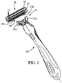
- the Figures illustrate different examples of a shaving cartridge 10 according to the disclosure, the shaving cartridge 10 comprising one or several blades 12 provided in a housing 13.
- the blade(s) 12 can be movably retained in the housing 13.
- the shaving cartridge 10 can be permanently or detachably attached to a razor handle 14.
- the shaving cartridge 10 can be pivotally or non-pivotally attached to the razor handle 14.
- the shaving cartridge 10 may comprise three blades 12, but the disclosure may not be limited to said number of blades. The number of blades may however vary between one and six blades for instance.
- the shaving cartridge 10 can be connected to the razor handle 14 to form a wet shaving razor 11. As depicted in figure 1 , the shaving cartridge 10 may be detachably connected to the handle 14 in order to be thrown when the blade edges are dulled.
- the bottom surface 18 of the shaving cartridge 10 may include two connecting members or rearwardly protruding connectors, i.e. two inwardly facing arcuate arms 17a shaped in correspondence with and adapted to receive lateral edges of shell bearing 17b provided onto the handle 14 for pivotally mounting the shaving cartridge 10 onto the handle 14.
- the housing 13 may have a top surface 16, a bottom surface 18, a front edge 20, a rear edge 22, and a pair of side edges 24 extending between the front edge 20 and the rear edge 22.
- the housing 13 may comprise at least one blade 12 disposed between the front edge 20 and the rear edge 22.
- Each blade 12 may have a cutting edge 15 extending toward the top surface 16.
- the cutting edges 15 of the blades 12 can be parallel to an axis X-X.
- a masking foil 26 may cover partially the cutting edge 15 of one or more blade(s) 12. As depicted in figures 3 and 4 , the masking foil 26 may cover partially the cutting edge 15 of all the five blades 12.
- the masking foil may cover partially the cutting edge 15 of a main blade and at least one adjacent blade 12.
- the blade the closest to the front edge 20 may be the first blade 12a.
- the main blade may also be the first blade 12a.
- the second blade 12b may be the adjacent blade to the first blade 12a.
- the third blade 12c may be adjacent to the second blade 12b.
- the third blade 12c may also be the middle blade.
- the two other blades 12d, 12e, i.e. the two blades closest to the rear edge 22, may be uncovered by the masking foil 26. These two other uncovered blades 12d, 12e, on the side of the back edge 22, may increase the shaving efficiency.
- a shaving plane S may be defined as a plane comprising a surface S1 and a surface S2.
- the surface S1 may be located at the top surface 16 of the cartridge.
- the surface S1 may be located close to the front portion 28 of the masking foil 26.
- the surface S2 may be located at the top surface 16 of the cartridge.
- the surface S2 may be located close to the back portion 30 of the masking foil 26. This partial blade coverage may provide therefore two different shaving geometries.
- the shaving process and experience may be different than the ones with conventional wet shaving cartridges.
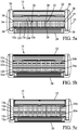
- the shaving cartridge 10 may comprise multiple masking foils 26.
- the multiple masking foils 26 can be separate by at least one blade 12. More precisely, as illustrated in figure 5b , a first masking foil 26a may cover partially the cutting edges 15 of the first blade 12a and the second blade 12b. A second masking foil 26b may cover partially the cutting edges 15 of the two blades 12d, 12e closest to the rear edge 22. The third blade 12c may be uncovered. The third blade 12c may lso be located between the first masking foil 26a and the second masking foil 26b.
- the main blade of the first masking foil 26a may be the first blade 12a.
- the main blade of the second masking foil may be the fourth blade 12d.
- the first masking foil 26a may cover partially the cutting edges 15 of the first, second a third blades 12a, 12b and 12c.
- the second masking foil may cover partially the two blades 12d, 12e closest to the rear edge 22.
- the third blade 12c could also be partially covered by the second masking foil 26b instead of the first masking foil 26a. Therefore, any other combination with regard to the number of masking foil(s) used, the number of cutting edge(s) may be covered and the location of the masking foil(s) on the covered cutting edge(s) may be possible.
- one and/or the other of the following features may be incorporated in the shaving cartridge of the disclosure, alone or in mutual combination:
- the masking foil 26 may comprise a front portion 28 and a back portion 30 and at least one ribbon 32 extending between the front portion 28 and the back portion 30.
- the front portion 28 may be located on the side of the front edge 20 and the back portion 30 may be located on the side of the rear edge 22.
- the masking foil 26 of the disclosure can further comprise at least one securing portion 34.
- the masking foil 26 can comprise two securing portions 34. Each of the two securing portions 34 may be placed close to the corresponding side edge 24.
- the shaving cartridge 10 can further comprise a blade retainer 36 as visible on figures 2 , 3 , 5 and 6 for instance.
- the blade retainer 36 may cover the blades 12 in order to retain them in the housing 13.
- the blade retainer 36 may be placed at one end of the blades 12, close to a side edge 24.
- the blade retainer 36 may extend further between the front edge 20 and the rear edge 22 of the cartridge 10.
- the blade retainer 36 may comprise a first leg 36a, a second leg 36b and a body 36c.
- the body 36c, first leg 36a and second leg 36b form a one-piece part.
- Each leg 36a, 36b may extend to an end 37.
- the first leg 36a of the blade retainer surrounds the side edge 24 of the housing 13, on the side of the rear edge 24. In other words, a portion of the blade retainer 36 may be wrapped around a portion of the housing 13.
- the second leg 36b of the blade retainer 36 may be received in a through hole 39 provided in the housing 13.
- the through hole 39 may extend transversally through the housing 13 between the top surface 16 and the bottom surface 18.
- the cartridge 10 can further comprise two blade retainers 36.
- the two blade retainers 36 can be additional members, or as depicted in figures 4 , 7 and 8 , the two securing portions 34 mounted on the housing 13 can act as blade retainers.
- the two securing portions 34 in the example of figures 4 , 7 and 8 may be attached in the housing 13, thanks to elasticity of the materials of the masking foil 26 and the cartridge 13. More precisely, the two securing portions 34 may be attached in the walls of the housing 13.
- the masking foil 26 may be press fitted in the housing.
- the masking foil 26 can also be snap fitted, welded or inserted in the housing 13 of the cartridge 10.
- the masking foil 26 can also be molded with the material of the cartridge 10.
- each securing portion 34 may be placed between the cutting edges 15 of the blades 12 and a blade retainer 36 (not shown in figure 4 ), securing thus the position along X axis of the masking foil 26 onto the cartridge 10.
- each blade retainer 36 may cover a corresponding securing portion 34 that may be placed between the blade retainer 36 and the cutting edges 15 of the blades 12.
- each securing portion 34 may be sandwiched between the blade retainer 36 and the blades 12.
- the securing portion 34 may have for example a rectangular shape, like a strip. Its shape may generally be identical to the body 36c of the blade retainer 36, which may cover the securing portion 34.
- the body 36c and the securing portion 34 may have approximatively the same length and width in a top view.
- the securing portion 34 covers the blades 12 along a transversal axis Y-Y from the front edge 20 to the rear edge 22 of the cartridge 13.
- the transversal axis Y-Y can be perpendicular to the axis X-X that is parallel to the blade edge(s).
- Each securing portion 34 may also have two joining members 38.
- Each joining member 38 may join respectively the front portion 28 of the masking foil 26 and the back portion 30 of the masking foil 26.
- the joining member 38 may allow a connection between the securing portion 34 and the remaining members of the masking foil 26.
- the masking foil 26 may comprise at least one ribbon 32.
- the masking foil 26 may comprise ten ribbons 32, but the disclosure may not be limited to said number of ribbons.
- the cutting edge 15 of each blade 12 may be covered on an area corresponding to a ribbon 32 placed above this area. If no ribbon 32 is placed above the cutting edge 15, the cutting edge may not be covered on this area. Therefore, if the masking foil 26 comprises only one ribbon 32, the cutting edge 15 may comprise only one covered area and two uncovered areas. If the masking foil 26 comprise ten ribbons 32, the cutting edge 15 may comprise ten covered areas and eleven uncovered areas. Thus, the cutting edge 15 may comprise as much covered areas as the number of ribbons 32 on the masking foil 26. When the covered areas are not on an extreme location of the cutting edge 15, then the number of uncovered areas may be of one more than the number of covered areas.
- Each ribbon 32 may extend transversally between the front portion 28 and the back portion 30 of the masking foil 26.
- An angle ⁇ view from the top as shown in figure 4 , can define the inclination of each ribbon between the axis X-X and the ribbon 32.
- This angle ⁇ can be comprised between 45° and 90° and can vary from one ribbon to another one on the same masking foil. More particularly, the angle ⁇ can be comprised between 15° and 90°. As illustrated in figure 4 , the angle ⁇ may be approximatively 90°.
- Each ribbon 32 may be connected to a front anchorage area 29a via a front bent portion 29 and to a back anchorage area 31a via a back bent portion 31 as visible for instance in figure 3 . These two bent portions 29, 31 may provide rigidity to the ribbons 32 when shaving.
- Each anchorage area 29a, 31a may be directed toward the bottom surface 18 of the housing, approximatively along a transversal axis Z-Z from the top surface 16 to the bottom surface 18 of the cartridge 13.
- Each anchorage area 29a, 31a may be in an extension of the respective bent portion 29, 31.
- the anchorage areas 29a, 31a may not be attached.
- the geometry of the masking foil 26 may allow the movements of the masking foil 26 along with the movement of the movable blades 12.
- the masking foil 26 can be movable in the housing due to the forces applied by the skin and hair during shaving action. Therefore, in comparison with a masking foil which may not follow the movement of the blades 12, the masking foil 26 may increase the adaptability of the blades 12 and the shaving surface of the skin of the user which may be in contact with the masking foil 26.
- the blades 12 can move in the cartridge 10 without compromising the closeness during shaving action.
- the front anchorage area 29a and the back anchorage area 31a each may make an angle with the axis Z-Z.
- the two angles can be equal or not.
- Figure 9a shows the angle ⁇ b between the back anchorage area 31a and the axis Z-Z may be smaller than the angle ⁇ f between the front anchorage area 29a and the axis Z-Z. This difference may allow a facility assembly between the masking foil 26 and the cartridge 13.
- the angle ⁇ f between the front anchorage area 29a and the axis Z-Z and the angle ⁇ b between the back anchorage area 31a and the axis Z-Z may be comprised between 0° and 25°.
- the shape of the ribbon 32, in the covered area may be flat viewed in a cross-sectional view. Its thickness T may be measured along the axis Z-Z from the side of the top surface 16 to the side of the bottom surface 18.
- the thickness T can be comprised between 20 ⁇ m and 5000 ⁇ m. In particular, the thickness T may be comprised between 40 ⁇ m and 60 ⁇ m.
- the thickness T may be for example of about 50 ⁇ m.
- the coverage percentage of the ribbons 32 can be comprised between 1% and 70%.In particular, the coverage percentage of the ribbons 32 may be comprised between 5% and 20%. For example, when the masking foil 26 comprises ten ribbons 32, the coverage percentage of the masking foil 26 by the ribbons 32 may be of about 20%.
- the ribbons 32 may be parallel to each other, transversally between the front portion and the back portion of the masking foil.
- the distance D between each ribbon may be defined as the perpendicular segment between the lateral sides of two adjacent ribbons 32.
- the width W of a ribbon 32 may be the distance between its two lateral sides.
- the distance D can be comprised between 3 mm and 3.25 mm.
- the width W can be comprised between 0.63 mm and 0.72 mm.
- the distance D between each adjacent ribbon 32 would be of about 3.15 mm.
- the width W is 0.68 mm.
- the number of apertures, or i.e. uncovered areas may be eleven.
- Figures 9a , 9b, 9c and 9d illustrate different shapes of the masking foil 32, in view from a side edge.
- the shape of the ribbon 32 may be flat.
- the ribbon 32 may be substantially parallel all along the axis Y-Y.
- the ribbon 32 may rests on each cutting edge 15.
- the shape of the ribbon 32 may be curved.
- the cutting edge 15 may follow the shape of the masking foil 26, thus the cutting edges may have an exposure between -200 ⁇ m to +200 ⁇ m.
- the curve can be a convex surface, according to axis Z-Z, from the bottom surface 18 to the top surface 16.
- the convex shape may provide a better accessibility in hard-to-reach anatomical regions. Thus, this shape may improve a shaving efficiency and precision.
- the shape surface may be corrugated.
- the masking foil 26 follows the shape of the cutting edge 15 and a part of the blades 12.
- the corrugations may stabilize and/or regulate the exposure and/ or the angle of each blade 12.
- the cutting edges may have an exposure between -200 ⁇ m to +200 ⁇ m.
- the blade angle may be the same, different or progressive.
- the corrugations may reduce the skin contact surface, thus reducing the shaving cartridge to skin friction.
- the shape of the ribbon 32 may be partly flat, viewed in a cross-sectional view.
- the ribbon 32 may comprise a groove 35.
- the groove 35 may be disposed approximatively in the middle of the ribbon 32 along its longitudinal axis. Any other combination with regard to the number of groove 35 and its position on the masking foil 26 may be possible.
- one and/or the other of the following features may be incorporated in the shaving cartridge of the disclosure, alone or in mutual combination:
- Such shape surfaces may allow to manage the exposure of the blades with respect to a shaving plane.
- the cutting edges may have an exposure between -200 ⁇ m to +200 ⁇ m.
- FIGS 10a , 10b and 11 illustrate another example of the present disclosure where elastic means are further provided.
- This example may be analogous to the example of figure 3 , except an elastic means 40 may be provided with the masking foil 26 between the bent portion and the anchorage area of the masking foil 26 as visible in figures 10a and 10b .
- an elastic means 40 can be provided on each side of a ribbon 32, between a bent portion and an anchorage area.
- an elastic means 40 can be placed between the front bent portion 29 and the anchorage area 29b.
- An elastic means 40 can also be provided on the masking foil 26 between the back bent portion 31 and the anchorage area 31b.
- the anchorage areas 29b, 31b may be attached in the housing 13 and can act as a blade retainer.
- Two slots 13a, 13b are provided in the housing 13. Each slot may be parallel to the top surface 16 or the bottom surface 18. Each slot may open outwardly the cartridge 13 and receives one of the two anchorage areas 29b, 31b.
- the elastic means can for example be a spring.
- the material of the masking foil can be at least locally sufficiently elastic to allow an elastic deformation of the elastic means. It can also be made of multiple folds.
- the geometry of the masking foil 26 allows the movement of the masking foil 26 along with the movement of the movable blades 12 whereas the anchorage areas may be unmovable. Even if an elastic means 40 is particularly suitable for a shaving cartridge 10 with movables blades 12, this example can be used with non-movable blades 12.
- the masking foil 26 can be provided without the elastic means 40.
- the masking foil 26 may not be provided with the elastic means 40.
- the masking foil can comprise the anchorage areas 29b, 31b.
- the two anchorage areas 29b, 31b may also be attached in the housing 13 and can act as a blade retainer.
- the blades 12 can move toward the bottom surface 18 during shaving.
- the movement of the blades may be stopped by stumbling against the masking foil 26.
- each blade 12 may be borne by a bent support 21.
- the blade(s) may comprise a cutting edge portion, a base portion and a bent portion intermediate the cutting edge portion and the base portion, which may be integrally formed.
- the blade(s) may not be borne by a bent support 21 and be welded below the masking foil. Therefore, the masking foil 26 can act as a shield for the blades 12.
- the masking foil 26 can also be elastically biased along with the movable blades 12.
- the shaving cartridge 10 comprises also blade retainer 36
- the blade retainer 36, together with the masking foil 26, may secure the blades 12 in the cartridge 10.
- the shaving cartridge 10 may comprise elastic fingers 19 (shown in figure 6 and 10a ).
- Such elastic fingers 19 are for example described in the publication WO2007147420 (in name of BIC VIOLEX). The movement of the masking foil 26 may be therefore indirectly managed by the elastic fingers 19.
- Figures 12a, 12b, 12c , 12d, 12e, 12f , 12g and 12h illustrate different examples of possible pattern of the masking foil 26 where the angle ⁇ between the front portion 28 and the ribbon 32 may not be equal to 90°.
- Figure 12i illustrates another example of possible pattern of the masking foil 26.
- all the ribbons 32 may be oriented in the same direction.
- the angle ⁇ may be substantially equal to 20°.
- the ribbons 32 may extend transversally between the front edge 20 and the rear edge 22, without contacting the securing portion 32.
- all the ribbons 32 may be oblique but not oriented in the same direction.
- the masking foil 26 may be symmetrically separated in its middle, for instance, in the direction from one side edge 24 to the other side edge 24.
- the first half of the ribbons 32, i.e. the ribbons 32 between the first side edge 24 and the middle of the masking foil 26 may be inclined in a direction whereas the second half of the ribbons 32, i.e. the ribbons 32 between the middle of the masking foil and the second side edge 24, may be inclined with the same angle ⁇ but in an opposite direction.
- the ribbons 32 may extend transversally between the front edge 20 and the rear edge 22, without contacting the securing portion 32.
- the ribbons 32 may extend transversally between the two-side edge 24.
- all the ribbons 32 may be oriented in the same direction.
- the ribbons 32 may extend transversally between the front edge 20 and the rear edge 22.
- the ribbons 32 closest to the side edge 24 may contact the securing portion 32.
- the ribbons 32 may be oriented according a circumferential direction.
- the shortest ribbon may extend from and to the front edge 20.
- the longest ribbon may extend between the frond side 20 and the rear side 22.
- any combination of number of ribbons and of their inclination angle can be provided on the masking foil:
- the pattern of the masking foil can manage the direction of the hairs in relation to the cutting edge.
- the oblique ribbons 32 provide hair cutting effect which improves shaving comfort during shaving.
- Figures 12g and 12h shows a masking foil 26 with particular ribbon patterns.
- the ribbons 32 form a skin contacting surface with a hexagonal configuration, like a honeycomb.
- ribbons 32 do not have a straight form.
- the ribbons 32 may comprise several circular shapes 42.
- the pattern of shapes 42 can also be rhomboidal.
- the shaving cartridge 10 comprises a masking foil 26 comprising an intermediate portion 33.
- the intermediate portion may extend in parallel to the front edge 20 and the rear edge 22.
- Each ribbon 32 may extend transversally from the front portion 28 or the back portion 30 to the intermediate portion 33.
- the angle ⁇ may be approximatively 90°.
- the ribbons 32 which may extend from the front portion 28 to the intermediate portion 33 may be staggered with respect to the ribbons 32 which may extend from the back portion 30 to the intermediate portion 33.
- the masking foil 26 can further comprise stainless steel. It can also comprise a material chosen among plastic material, composite, aluminum, aluminum alloys and/or noble metals chosen among gold or platinum. Metals such as aluminum and its alloys may improve corrosion and oxidation resistance of the blades 12 through anodic protection process. Thus, since the blade retainer 36, which may comprise aluminum, may no longer contacting blades 12, the masking foil may play the role of anodic protection.
- the masking foil can comprise a wound healing and/or an anti-bacterial agent.
- the masking foil can also comprise a lubricating coating, such as hydrophobic or hydrophilic, such as polyfluorocarbon, for example polytetrafluoroethylene (PTFE), or hydrogel coating. This coating provides a reduction of the friction between the shaving cartridge and the skin.
- a lubricating coating such as hydrophobic or hydrophilic, such as polyfluorocarbon, for example polytetrafluoroethylene (PTFE), or hydrogel coating. This coating provides a reduction of the friction between the shaving cartridge and the skin.
- the masking foil can also have color properties. For instance, different colors can be provided on the masking foil in order to distinguish the male or female utilization. For instance, the masking foil can be blue when intended to a man shaving razor, and red or pink when intended to a woman shaving razor.
- the masking foil can also be provided with a material which has properties allowing a changing of the color after a particular number of uses. For instance, the masking foil can be green when never utilized and red when worn.
- the masking foil 26 may be placed above the top surface 16 of the shaving cartridge 10.
- the bent portions 29, 30 may be wrapped around the front edge 20 and the rear edge 22, extending toward the bottom surface 18 of the shaving cartridge.
- the masking foil 10 may act as a blade retainer 36.
- a shaving cartridge 10 comprising one or several blades 12 provided in a housing 13, in which the blade(s) 12 can be movably or fixedly retained in the housing 13.
- the disclosure is not limited to the previous features.
- the following examples can also apply to the masking foil of the disclosure.
- the corrugations of the masking foil may comprise a lubricant or a shaving aid element. More precisely, the lubricant or the shaving aid element may be located on each concavity 57 of the corrugations.
- the height of the lubricant or the shaving aid element may be up to 1.0 mm, improving glidness of the shaving razor 10 on the skin during shaving and reducing skin bulge, nicks and cuts during shaving.
- the lubricant or the shaving aid element is a hydrophobic material, the rinsability of the masking foil 26 may be improved.
- the ribbons 32 may comprise bristles 56.
- the bristles 56 may be flexible.
- the bristles 56 may have rounded tips.
- the height of the bristles 56 may be up to 0.6 mm, may be spaced at least about 0.3 mm from a next adjacent bristle 56 and may have a width defined at the respective root at least about 0.1 mm.
- the bristles 56 can move during shaving.
- the bristles 56 may face the top surface 16.
- the bristles 56 may provide a soft contact with the skin during shaving, a massage of the skin during shaving.
- the ribbons 32 may comprise sphere shaped protrusions 61.
- the sphere-shaped protrusions 61 may face toward the top surface 16.
- the height of the sphere shaped protrusions 61 may be up to 0.6 mm.
- the sphere-shaped protrusions 61 may provide a massage of the skin during shaving.
- the ribbons 32 may comprise extruded protrusions 65.
- the extruded protrusions may have a rectangular or a conical shape. The conical shape ends with an aperture 66.
- the extruded protrusions 65 may face toward the top surface 16.
- the extruded protrusions 65 may comprise lubricant or shaving aid, which may be stored in the apertures 66.
- an electrical current can go through the masking foil 26, the extruded protrusions 65 may be heated and the release rate of the lubricant or shaving aid may be increased.
- the extruded protrusions 65 may be covered by a polymer film.
- An electrical current can go through the masking foil 26, the electrical current may control the porosity of the polymer film, the pores of the polymer film may expand and the release rate of the lubricant or the shaving aid from the apertures 66 may be increased. All the above mentioned examples, may improve hair removal and reduce irritations during shaving.
- the masking foil 26 may have an organic pattern. The organic pattern may have the advantage to follow the skin contours and to guide the hair smoothly, providing a better hair alignment, smoother shaving and better hair removal.
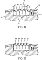
- the ribbon 32 may comprise pikes 58 as shark fins.
- the tip 59 of the pikes 58 may be oriented towards the back portion 30 of the masking foil.
- the pikes 58 may be oriented toward the top surface 16.
- the base 60 of the pikes 58 may be oriented towards the front portion 28 of the masking foil 26.
- the height of pikes 58 may be up to 0.6 mm.
- the pikes 58 may provide a mechanical exfoliation of the skin, as a pre-shave skin preparation phase.
- the pikes 58 may provide a dermo-dynamic feature, improving glidness of the shaving razor 10 on the skin during shaving.
- the ribbons 32 may comprise rounded protrusions 62.
- the rounded protrusions 62 may face toward the top surface 16 of the housing.
- the height of the rounded protrusions 62 may be up to 0.6 mm.
- the rounded protrusions 62 may eliminate the bulging effect that may happen during the shaving.
- the masking foil 26 when the masking foil 26 is not fixedly mounted in the housing and does not cover partially the cutting edge 15 of all the blades 12, for example as illustrated in figure 6 , the blades 12 that are uncovered by the masking foil 26 can be movable, or fixedly mounted in the housing 13. Moreover, the cutting edges 15 may have different exposure, between -200 ⁇ m to +200 ⁇ m. In addition, the masking foil 26 may improve hair removal and reduce nicks and cuts during shaving.
- the shape surface of the masking foil 26 may be corrugated.
- the tip 63 of each corrugation may be sharp.
- Each corrugation 63 can be used for stabilizing and regulating the angle of each blade 12.
- the angle also called shaving angle
- the shaving angle may be the angle between the upper surface of the blade 12 and the shaving plane S at rest position (non-shaving).
- the shaving angle may be between 5° and 30°.
- the shaving angle of each blade may be the same, totally different, progressive or any combination thereof. For example, when the shaving cartridge 10 comprises five blades, the shaving angle ⁇ 1 of the first blade 12a may be smaller than the shaving angle ⁇ 2 of the second blade 12b.
- each corrugation may comprise two tips 63.
- the first tip 63a may correspond to the cutting edge 15 of the blade 12 located below.
- the second tip 63b may correspond to an additional tip located above the blade 12.
- This masking foil may reduce the total number of strokes during shaving.
- the shape surface of the masking foil 26 may be corrugated.
- the corrugations 64 may be located on the side of the front portion 28 of the masking foil 26. In further aspects, the corrugations 64 may dispersed in another part or in the whole surface of the masking foil 26. Actually, each corrugation 64 has an amplitude different from each other. The amplitude may be up to 0,6 mm. For example, the amplitude A1 of the corrugation 64 of the first blade 12a may be larger than the amplitude A2 of the corrugation 64 of the second blade 12b. Likewise, the amplitude A2 of the corrugation 64 of the second blade 12b may be larger than the amplitude A3 of the corrugation 64 of the third blade 12c.
- the amplitude A3 of the corrugation 64 of the third blade 12c may be larger than the amplitude A4 of the corrugation 64 of the fourth blade 12d.
- the amplitude A4 of the corrugation 64 of the fourth blade 12d may be larger than the amplitude A5 of the corrugation 64 of the fifth blade 12e.
- the amplitude A5 may be null.
- each corrugation 64 may press each blade differently.
- Each blade 12 may have different or a progressive exposure, between -200 ⁇ m to +200 ⁇ m.
- the first corrugation 64 of the first blade 12a may press the first blade 12a creating a negative geometry.
- the second corrugation 64 of the second blade 12b may press the second blade 12b a little bit lower than the first and so on, till the fifth blade 12e.
- the masking foil 26 may not comprise corrugations 64 above the fourth blade 12d and/or the fifth blade 12e.
- the masking foil may not press the fourth 12d and/or the fifth blade 12e.
- the forth 12d and/or the fifth blade 12e may have different geometry than the first blade 12a, second blade 12b and the third blade 12c.
- the corrugations 64 may reduce the shaving cartridge to skin friction, reduce skin bulge and improve hair alignment during shaving.
- the ribbon 32 may form a kind of step 67.
- the ribbon 32 may comprise as many steps 67 as blades 12.
- the steps 67 may provide a better shaving on difficult areas of skin, for example the chin, reduce nicks and cut irritations during shaving.
- the ribbons 32 may comprise small barbs.
- the small barbs may be split into clumps 69 along the ribbon 32.
- the height of the clumps 69 may be up to 0.6 mm and the distance between two adjacent clumps 69 may be more that 0.1 mm.
- the small barbs may provide a mechanical exfoliation of the skin.
- the mechanical exfoliation may be a sebum removal.
- a masking foil 26 for a shaving cartridge (10), as shown for example in figure 3 can be made by using several methods, such as photo etching, laser cutting, stamping, electrical discharge machining, water jet cutting or electroforming.
- the masking foil can be made of a flat strip of material.
- the strip has an upper portion and a lower portion.
- the material is chosen among plastic material, composite, aluminum, aluminum alloys and/or noble metals chosen among gold or platinum.
- the strip material may pass through a stamping station performing holes in the strip, forming the pattern of the masking foil 26, as shown in figure 10a .
- the masking foil 26 may pass through a bending station.
- the bending station may comprise a slot which receives the strip.
- the upper portion and the lower portion of the strip project outside of the slot.
- the upper portion and the lower portion may be bent inwardly about a bending axis, forming a front bent portion 29 and a back bent portion 31 of the masking foil.
- the front bent portion 29 and the back bent portion 31 of the masking foil 26 may have the same or different radius of curvature.
- the radius of curvature can be range between 0.10 mm to 0.70 mm.
- an elastic means 40 may be formed between the front bent portion 29 and the anchorage area 29b of the masking foil 26 as visible in figures 10a and 10b .
- the elastic means 40 can for example be a spring.
- An elastic means 40 can also be formed between the back bent portion 31 and the anchorage area 31b.
- each anchorage area 29b, 31b may be bent outwardly forming a portion which may fit into each slot 13a, 13b, as shown in figures 10b and 10c .
- the side edges of each ribbon 32 may be grinded or electrochemically etched, providing additional cutting edges of different profiles as shown in figures 19, 20 .
Landscapes
- Life Sciences & Earth Sciences (AREA)
- Forests & Forestry (AREA)
- Engineering & Computer Science (AREA)
- Mechanical Engineering (AREA)
- Dry Shavers And Clippers (AREA)
Claims (14)
- Cartouche de rasage (10) comprenant :un boîtier (13) ayant une surface supérieure (16), une surface inférieure (18), un bord avant (20), un bord arrière (22) et une paire de bords latéraux (24) s'étendant entre le bord avant (20) et le bord arrière (22), le boîtier (13) ayant une lame (12) principale disposée entre le bord avant (20) et le bord arrière (22), la lame (12) principale ayant un bord de coupe (15) principal s'étendant vers la surface supérieure (16), la lame (12) principale étant mobile dans le boîtier,la cartouche de rasage comprenant un film de protection (26) comprenant une partie avant (28) située en avant du bord de coupe (15) principal et une partie arrière (30) située vers l'arrière du bord de coupe (15) principal, le film de protection (26) comprenant en outre au moins un ruban (32) qui recouvre partiellement le bord de coupe (15) principal,l'au moins un ruban (32) comprenant une partie courbée avant (29) reliée à la partie avant (28) et une partie courbée arrière (31) reliée à la partie arrière (30) du film de protection (32), l'avant (29) et la partie courbée arrière (31) étant dirigés vers la surface inférieure (18),le film de protection (26) étant inséré dans le boîtier (13) de la cartouche (10), et l'au moins un ruban (32) comprenant des caractéristiques/parties saillantes faisant face à la surface supérieure du boîtier.
- Cartouche de rasage (10) selon la revendication 1, l'au moins un ruban (32) comprenant des saillies arrondies (62) faisant face à la surface supérieure (16) du boîtier (13).
- Cartouche de rasage (10) selon la revendication 1, l'au moins un ruban (32) comprenant des poils (56), les poils (56) étant conçus pour se déplacer pendant le rasage.
- Cartouche de rasage (10) selon la revendication 1, l'au moins un ruban (32) comprenant des saillies extrudées (65) ayant une forme conique et se terminant par une ouverture (66).
- Cartouche de rasage (10) selon la revendication 1, l'au moins un ruban (32) comprenant des piques (58), qui sont orientées vers la surface supérieure (16) du boîtier (13).
- Cartouche de rasage (10) selon la revendication 1, l'au moins un ruban (32) comprenant au moins un sommet (63a, 63b).
- Cartouche de rasage (10) selon la revendication 1, l'au moins un ruban (32) comprenant des ondulations (64), chaque ondulation (64) ayant une amplitude (A1, A2, A3, A4, A5) différente l'une de l'autre.
- Cartouche de rasage (10) selon la revendication 1, l'au moins un ruban (32) comprenant des paliers (67).
- Cartouche de rasage (10) selon la revendication 1, l'au moins un ruban (32) comprenant des petites pointes divisées en mottes (69) le long de l'au moins un ruban (32).
- Cartouche de rasage (10) selon les revendications 1 à 9, le film de protection (26) comprenant un moyen élastique (40).
- Cartouche de rasage (10) selon l'une quelconque des revendications 1 à 9, le film de protection (26) comprenant au moins une partie fixation (34), la partie fixation (34) étant placée sur la lame (12) principale, vers la surface supérieure (16) et à proximité de l'un des deux bords latéraux (24).
- Cartouche de rasage (10) selon la revendication 11, comprenant en outre au moins une lame (12) supplémentaire, l'au moins une lame (12) supplémentaire comportant un bord de coupe (15) supplémentaire, l'au moins un ruban (32) recouvrant partiellement à la fois le bord de coupe (15) principal et l'au moins un bord de coupe (15) supplémentaire, et la partie fixation (34) étant placée sur la lame (12) principale et sur l'au moins une lame (12) supplémentaire, vers la surface supérieure (16) et à proximité de l'un des deux bords latéraux (24).
- Cartouche de rasage (10) selon l'une quelconque des revendications 1 à 12, le film de protection (26) comprenant un agent de cicatrisation et/ou un antibactérien.
- Cartouche de rasage (10) selon l'une quelconque des revendications 1 à 13, le film de protection (26) comprenant un revêtement de lubrification.
Priority Applications (1)
| Application Number | Priority Date | Filing Date | Title |
|---|---|---|---|
| EP21215809.1A EP3998143B1 (fr) | 2016-07-28 | 2017-07-27 | Tête de rasoir comprenant un film de protection |
Applications Claiming Priority (3)
| Application Number | Priority Date | Filing Date | Title |
|---|---|---|---|
| US201662367787P | 2016-07-28 | 2016-07-28 | |
| EP2016068017 | 2016-07-28 | ||
| PCT/EP2017/069062 WO2018019953A1 (fr) | 2016-07-28 | 2017-07-27 | Tête de rasoir comprenant un film de protection |
Related Child Applications (1)
| Application Number | Title | Priority Date | Filing Date |
|---|---|---|---|
| EP21215809.1A Division EP3998143B1 (fr) | 2016-07-28 | 2017-07-27 | Tête de rasoir comprenant un film de protection |
Publications (2)
| Publication Number | Publication Date |
|---|---|
| EP3490763A1 EP3490763A1 (fr) | 2019-06-05 |
| EP3490763B1 true EP3490763B1 (fr) | 2022-01-05 |
Family
ID=59558392
Family Applications (3)
| Application Number | Title | Priority Date | Filing Date |
|---|---|---|---|
| EP17752313.1A Active EP3490764B1 (fr) | 2016-07-28 | 2017-07-27 | Cartouche de rasage comprenant une feuille de masquage |
| EP21215809.1A Active EP3998143B1 (fr) | 2016-07-28 | 2017-07-27 | Tête de rasoir comprenant un film de protection |
| EP17749157.8A Active EP3490763B1 (fr) | 2016-07-28 | 2017-07-27 | Tête de rasoir comprenant un film de protection |
Family Applications Before (2)
| Application Number | Title | Priority Date | Filing Date |
|---|---|---|---|
| EP17752313.1A Active EP3490764B1 (fr) | 2016-07-28 | 2017-07-27 | Cartouche de rasage comprenant une feuille de masquage |
| EP21215809.1A Active EP3998143B1 (fr) | 2016-07-28 | 2017-07-27 | Tête de rasoir comprenant un film de protection |
Country Status (3)
| Country | Link |
|---|---|
| US (2) | US11045965B2 (fr) |
| EP (3) | EP3490764B1 (fr) |
| WO (2) | WO2018019953A1 (fr) |
Families Citing this family (9)
| Publication number | Priority date | Publication date | Assignee | Title |
|---|---|---|---|---|
| WO2018019953A1 (fr) * | 2016-07-28 | 2018-02-01 | Bic-Violex Sa | Tête de rasoir comprenant un film de protection |
| EP3527339A1 (fr) * | 2018-02-20 | 2019-08-21 | Koninklijke Philips N.V. | Peigne pour un appareil de coupe de cheveux |
| EP3689560A1 (fr) * | 2019-01-31 | 2020-08-05 | Bic Violex S.A. | Tête de rasage à intervalle inter-lame accru |
| EP3946849A1 (fr) * | 2019-04-04 | 2022-02-09 | The Gillette Company LLC | Cartouche de rasoir |
| USD926374S1 (en) | 2019-04-04 | 2021-07-27 | The Gillette Company Llc | Shaving razor cartridge cover |
| EP3730260B1 (fr) * | 2019-04-23 | 2024-05-29 | BIC Violex Single Member S.A. | Adaptateur de soin de protection |
| USD1016392S1 (en) | 2020-09-24 | 2024-02-27 | The Gillette Company Llc | Shaving razor cartridge |
| CN116997448A (zh) * | 2021-03-12 | 2023-11-03 | Edgewell个人护理品牌有限责任公司 | 剃刀刀片架 |
| EP4098414B1 (fr) | 2021-05-31 | 2024-03-06 | BIC Violex Single Member S.A. | Feuille de masquage de lame dotée d'éléments de fixation inter-lames |
Family Cites Families (39)
| Publication number | Priority date | Publication date | Assignee | Title |
|---|---|---|---|---|
| US3675325A (en) * | 1970-07-06 | 1972-07-11 | Gunnar P Michelson | Razor edge safety guard apparatus |
| US4211006A (en) * | 1979-01-02 | 1980-07-08 | Warner-Lambert Company | Guarded razor blade |
| FR2559657B1 (fr) | 1984-02-22 | 1987-05-29 | Bernard Lissague | Dispositif support repliable formant en particulier table pliante |
| FR2599657A1 (fr) * | 1986-06-09 | 1987-12-11 | Viart Joris | Dispositif adaptable sur lames de rasoir mecanique, pour elevation de la hauteur de coupe |
| DE8711506U1 (fr) * | 1987-08-25 | 1987-10-08 | Wilkinson Sword Gmbh, 5650 Solingen, De | |
| US4914817A (en) * | 1988-07-01 | 1990-04-10 | The Gillette Company | Razor head with riblets |
| US4985995A (en) * | 1988-09-08 | 1991-01-22 | Wilkinson Sword Gesellschaft Mit Beschrankter Haftung | Razor head, especially a razor blade unit |
| US5205040A (en) * | 1991-11-05 | 1993-04-27 | Werner Eric J | Apparatus for shaving |
| GB2265328B (en) * | 1992-03-13 | 1995-05-10 | Wilkinson Sword Gmbh | Razor head of a wet razor |
| JP2978388B2 (ja) * | 1993-11-29 | 1999-11-15 | フェザー安全剃刀株式会社 | 剃刀ユニット |
| JPH07303767A (ja) * | 1994-05-13 | 1995-11-21 | Feather Safety Razor Co Ltd | 替え刃カートリッジ |
| US5456009A (en) * | 1994-08-23 | 1995-10-10 | Warner-Lambert Company | Multi-blade razor head with improved performance |
| US5630275A (en) * | 1994-08-23 | 1997-05-20 | Warner-Lambert Company | Multi-blade razor head with improved performance |
| US5579580A (en) * | 1995-03-31 | 1996-12-03 | Warner-Lambert Company | Bi-directional wire-wrapped blade cartridge |
| CA2239155A1 (fr) | 1996-03-14 | 1997-09-18 | Warner-Lambert Company | Systemes de rasage a element de contact avec la peau en matiere alveolaire |
| JP2952587B1 (ja) | 1998-03-30 | 1999-09-27 | 株式会社貝印刃物開発センター | 安全かみそり |
| CA2391308A1 (fr) | 1999-07-27 | 2001-02-01 | Edward A. Andrews | Rasoirs a main a patins |
| DE10014132A1 (de) | 2000-03-22 | 2001-09-27 | Zahnradfabrik Friedrichshafen | Unter Last schaltbares, mehrgängiges Wendegetriebe |
| US20040128835A1 (en) * | 2002-10-21 | 2004-07-08 | Eveready Battery Company, Inc. | Bidirectional shaving cartridge and razor including same |
| JP2006521159A (ja) * | 2003-03-26 | 2006-09-21 | エヴァレディ バッテリー カンパニー インク | 針金付き刃セットを備えたウェットシェービング装置 |
| AT7252U1 (de) * | 2003-08-12 | 2004-12-27 | Siegfried Pfister | Nassrasierer mit zumindest einer rasierklinge, sowie klingenprotektor, protektorklipse und protektorfolie für einen nassrasierer |
| US8015710B1 (en) | 2004-05-27 | 2011-09-13 | Harley Zyla | Shaving device and method of use |
| USD526089S1 (en) | 2005-04-04 | 2006-08-01 | Eveready Battery Company, Inc. | Razor cartridge |
| USD524483S1 (en) | 2005-04-04 | 2006-07-04 | Eveready Battery Company, Inc. | Guard bar |
| CA2655513C (fr) | 2006-06-20 | 2012-01-03 | Bic-Violex S.A. | Tete de lame de rasoir et rasoir de securite comprenant une telle lame |
| FR2906180B1 (fr) | 2006-09-21 | 2008-12-05 | Bic Soc | Dispositif et procede de rasage a lame |
| WO2008128152A1 (fr) * | 2007-04-13 | 2008-10-23 | Eveready Battery Company, Inc. | Accessoire de rasage multi-usage |
| GB2461337B (en) * | 2008-07-02 | 2012-09-05 | William James Herbert Jenkins | Shaving razor |
| EP2537649B1 (fr) * | 2011-06-21 | 2013-07-17 | The Gillette Company | Cartouche de rasoir dotée d'un élément qui vient en contact avec la peau |
| WO2014119808A1 (fr) * | 2013-01-31 | 2014-08-07 | 주식회사 도루코 | Cartouche de rasoir à attache de sécurité et rasoir l'utilisant |
| PL2853362T3 (pl) * | 2013-09-25 | 2017-01-31 | Bic Violex S.A. | Kaseta nożyków do golenia |
| EP3322566B1 (fr) * | 2015-07-16 | 2019-09-18 | BIC-Violex S.A. | Dispositif de protection pour cartouche de rasoir, ensemble de rasage, rasoir de rasage à sec et procédé d'utilisation d'un tel rasoir de rasage à sec |
| US20190118397A1 (en) * | 2017-10-19 | 2019-04-25 | Eran Drori | Wet-Shave Razor Guard |
| CA3018095A1 (fr) * | 2016-03-18 | 2017-09-21 | Personal Care Marketing And Research, Inc. | Cartouche de rasoir |
| US10144142B1 (en) * | 2016-04-21 | 2018-12-04 | Stubl Llc | Spacer for razor blade for creating and maintaining a stubble shave appearance |
| WO2018019953A1 (fr) * | 2016-07-28 | 2018-02-01 | Bic-Violex Sa | Tête de rasoir comprenant un film de protection |
| EP3292963B1 (fr) * | 2016-09-09 | 2020-04-01 | The Gillette Company LLC | Cartouche de rasoir |
| EP3417738B1 (fr) * | 2017-06-23 | 2020-03-04 | Braun GmbH | Épilateur |
| EP3730260B1 (fr) * | 2019-04-23 | 2024-05-29 | BIC Violex Single Member S.A. | Adaptateur de soin de protection |
-
2017
- 2017-07-27 WO PCT/EP2017/069062 patent/WO2018019953A1/fr unknown
- 2017-07-27 US US16/310,235 patent/US11045965B2/en active Active
- 2017-07-27 WO PCT/EP2017/069057 patent/WO2018019951A1/fr unknown
- 2017-07-27 US US16/310,203 patent/US10786914B2/en active Active
- 2017-07-27 EP EP17752313.1A patent/EP3490764B1/fr active Active
- 2017-07-27 EP EP21215809.1A patent/EP3998143B1/fr active Active
- 2017-07-27 EP EP17749157.8A patent/EP3490763B1/fr active Active
Non-Patent Citations (1)
| Title |
|---|
| None * |
Also Published As
| Publication number | Publication date |
|---|---|
| US20190255720A1 (en) | 2019-08-22 |
| EP3490763A1 (fr) | 2019-06-05 |
| US20200009753A1 (en) | 2020-01-09 |
| EP3998143B1 (fr) | 2024-04-17 |
| EP3490764A1 (fr) | 2019-06-05 |
| EP3490764B1 (fr) | 2020-07-15 |
| WO2018019951A1 (fr) | 2018-02-01 |
| US10786914B2 (en) | 2020-09-29 |
| WO2018019953A1 (fr) | 2018-02-01 |
| US11045965B2 (en) | 2021-06-29 |
| EP3998143A1 (fr) | 2022-05-18 |
Similar Documents
| Publication | Publication Date | Title |
|---|---|---|
| EP3490763B1 (fr) | Tête de rasoir comprenant un film de protection | |
| US11712814B2 (en) | Razor cartridge | |
| AU2017327812B2 (en) | Bidirectional shaving device | |
| AU2020213275B2 (en) | Shaving razor cartridge and method of assembling | |
| KR102356759B1 (ko) | 면도기 카트리지 | |
| US20090188112A1 (en) | Shaving razor with modular blade pairs | |
| EP3110598B1 (fr) | Cartouche de lames de rasage et rasoir comprenant une telle cartouche de lames de rasage | |
| EP3730260B1 (fr) | Adaptateur de soin de protection | |
| US20060277759A1 (en) | Inter-blade guard and method for manufacturing same | |
| EP3237156B1 (fr) | Cartouche de lames de rasage et rasoir comprenant une telle cartouche de lames de rasage | |
| CA2784116A1 (fr) | Cartouche de rasoir munie d'un element non-coupant | |
| KR20140053107A (ko) | 부품 수가 감소되어 있고 움직임 범위가 확장된 면도기 카트리지 | |
| EP3292963B1 (fr) | Cartouche de rasoir | |
| EP4067025B1 (fr) | Éléments de lame | |
| EP4098414B1 (fr) | Feuille de masquage de lame dotée d'éléments de fixation inter-lames | |
| WO1996032232A1 (fr) | Systeme de rasage dynamique multidirectionnel |
Legal Events
| Date | Code | Title | Description |
|---|---|---|---|
| STAA | Information on the status of an ep patent application or granted ep patent |
Free format text: STATUS: UNKNOWN |
|
| STAA | Information on the status of an ep patent application or granted ep patent |
Free format text: STATUS: THE INTERNATIONAL PUBLICATION HAS BEEN MADE |
|
| PUAI | Public reference made under article 153(3) epc to a published international application that has entered the european phase |
Free format text: ORIGINAL CODE: 0009012 |
|
| STAA | Information on the status of an ep patent application or granted ep patent |
Free format text: STATUS: REQUEST FOR EXAMINATION WAS MADE |
|
| 17P | Request for examination filed |
Effective date: 20181220 |
|
| AK | Designated contracting states |
Kind code of ref document: A1 Designated state(s): AL AT BE BG CH CY CZ DE DK EE ES FI FR GB GR HR HU IE IS IT LI LT LU LV MC MK MT NL NO PL PT RO RS SE SI SK SM TR |
|
| AX | Request for extension of the european patent |
Extension state: BA ME |
|
| DAV | Request for validation of the european patent (deleted) | ||
| DAX | Request for extension of the european patent (deleted) | ||
| STAA | Information on the status of an ep patent application or granted ep patent |
Free format text: STATUS: EXAMINATION IS IN PROGRESS |
|
| 17Q | First examination report despatched |
Effective date: 20200402 |
|
| STAA | Information on the status of an ep patent application or granted ep patent |
Free format text: STATUS: EXAMINATION IS IN PROGRESS |
|
| GRAP | Despatch of communication of intention to grant a patent |
Free format text: ORIGINAL CODE: EPIDOSNIGR1 |
|
| STAA | Information on the status of an ep patent application or granted ep patent |
Free format text: STATUS: GRANT OF PATENT IS INTENDED |
|
| INTG | Intention to grant announced |
Effective date: 20210722 |
|
| RIN1 | Information on inventor provided before grant (corrected) |
Inventor name: GALANIS, CHRISTOS Inventor name: EFTHIMIADIS, DIMITRIOS Inventor name: BRELLIS, CHRISTOFOROS - ATHANASIOS Inventor name: MALLIAROS, IOANNIS Inventor name: PETRATOU, MARIA Inventor name: TSEGENIDIS, ANESTIS Inventor name: MOUSTAKAS, PANAGIOTIS Inventor name: PAPACHRISTOS, VASILEIOS |
|
| GRAS | Grant fee paid |
Free format text: ORIGINAL CODE: EPIDOSNIGR3 |
|
| GRAA | (expected) grant |
Free format text: ORIGINAL CODE: 0009210 |
|
| STAA | Information on the status of an ep patent application or granted ep patent |
Free format text: STATUS: THE PATENT HAS BEEN GRANTED |
|
| AK | Designated contracting states |
Kind code of ref document: B1 Designated state(s): AL AT BE BG CH CY CZ DE DK EE ES FI FR GB GR HR HU IE IS IT LI LT LU LV MC MK MT NL NO PL PT RO RS SE SI SK SM TR |
|
| REG | Reference to a national code |
Ref country code: GB Ref legal event code: FG4D |
|
| REG | Reference to a national code |
Ref country code: CH Ref legal event code: EP |
|
| REG | Reference to a national code |
Ref country code: AT Ref legal event code: REF Ref document number: 1460121 Country of ref document: AT Kind code of ref document: T Effective date: 20220115 |
|
| REG | Reference to a national code |
Ref country code: DE Ref legal event code: R096 Ref document number: 602017051894 Country of ref document: DE |
|
| REG | Reference to a national code |
Ref country code: IE Ref legal event code: FG4D |
|
| REG | Reference to a national code |
Ref country code: LT Ref legal event code: MG9D |
|
| REG | Reference to a national code |
Ref country code: NL Ref legal event code: MP Effective date: 20220105 |
|
| RAP4 | Party data changed (patent owner data changed or rights of a patent transferred) |
Owner name: BIC VIOLEX SINGLE MEMBER S.A. |
|
| REG | Reference to a national code |
Ref country code: AT Ref legal event code: MK05 Ref document number: 1460121 Country of ref document: AT Kind code of ref document: T Effective date: 20220105 |
|
| PG25 | Lapsed in a contracting state [announced via postgrant information from national office to epo] |
Ref country code: NL Free format text: LAPSE BECAUSE OF FAILURE TO SUBMIT A TRANSLATION OF THE DESCRIPTION OR TO PAY THE FEE WITHIN THE PRESCRIBED TIME-LIMIT Effective date: 20220105 |
|
| PG25 | Lapsed in a contracting state [announced via postgrant information from national office to epo] |
Ref country code: SE Free format text: LAPSE BECAUSE OF FAILURE TO SUBMIT A TRANSLATION OF THE DESCRIPTION OR TO PAY THE FEE WITHIN THE PRESCRIBED TIME-LIMIT Effective date: 20220105 Ref country code: RS Free format text: LAPSE BECAUSE OF FAILURE TO SUBMIT A TRANSLATION OF THE DESCRIPTION OR TO PAY THE FEE WITHIN THE PRESCRIBED TIME-LIMIT Effective date: 20220105 Ref country code: PT Free format text: LAPSE BECAUSE OF FAILURE TO SUBMIT A TRANSLATION OF THE DESCRIPTION OR TO PAY THE FEE WITHIN THE PRESCRIBED TIME-LIMIT Effective date: 20220505 Ref country code: NO Free format text: LAPSE BECAUSE OF FAILURE TO SUBMIT A TRANSLATION OF THE DESCRIPTION OR TO PAY THE FEE WITHIN THE PRESCRIBED TIME-LIMIT Effective date: 20220405 Ref country code: LT Free format text: LAPSE BECAUSE OF FAILURE TO SUBMIT A TRANSLATION OF THE DESCRIPTION OR TO PAY THE FEE WITHIN THE PRESCRIBED TIME-LIMIT Effective date: 20220105 Ref country code: HR Free format text: LAPSE BECAUSE OF FAILURE TO SUBMIT A TRANSLATION OF THE DESCRIPTION OR TO PAY THE FEE WITHIN THE PRESCRIBED TIME-LIMIT Effective date: 20220105 Ref country code: ES Free format text: LAPSE BECAUSE OF FAILURE TO SUBMIT A TRANSLATION OF THE DESCRIPTION OR TO PAY THE FEE WITHIN THE PRESCRIBED TIME-LIMIT Effective date: 20220105 Ref country code: BG Free format text: LAPSE BECAUSE OF FAILURE TO SUBMIT A TRANSLATION OF THE DESCRIPTION OR TO PAY THE FEE WITHIN THE PRESCRIBED TIME-LIMIT Effective date: 20220405 |
|
| PG25 | Lapsed in a contracting state [announced via postgrant information from national office to epo] |
Ref country code: PL Free format text: LAPSE BECAUSE OF FAILURE TO SUBMIT A TRANSLATION OF THE DESCRIPTION OR TO PAY THE FEE WITHIN THE PRESCRIBED TIME-LIMIT Effective date: 20220105 Ref country code: LV Free format text: LAPSE BECAUSE OF FAILURE TO SUBMIT A TRANSLATION OF THE DESCRIPTION OR TO PAY THE FEE WITHIN THE PRESCRIBED TIME-LIMIT Effective date: 20220105 Ref country code: GR Free format text: LAPSE BECAUSE OF FAILURE TO SUBMIT A TRANSLATION OF THE DESCRIPTION OR TO PAY THE FEE WITHIN THE PRESCRIBED TIME-LIMIT Effective date: 20220406 Ref country code: FI Free format text: LAPSE BECAUSE OF FAILURE TO SUBMIT A TRANSLATION OF THE DESCRIPTION OR TO PAY THE FEE WITHIN THE PRESCRIBED TIME-LIMIT Effective date: 20220105 Ref country code: AT Free format text: LAPSE BECAUSE OF FAILURE TO SUBMIT A TRANSLATION OF THE DESCRIPTION OR TO PAY THE FEE WITHIN THE PRESCRIBED TIME-LIMIT Effective date: 20220105 |
|
| PG25 | Lapsed in a contracting state [announced via postgrant information from national office to epo] |
Ref country code: IS Free format text: LAPSE BECAUSE OF FAILURE TO SUBMIT A TRANSLATION OF THE DESCRIPTION OR TO PAY THE FEE WITHIN THE PRESCRIBED TIME-LIMIT Effective date: 20220505 |
|
| REG | Reference to a national code |
Ref country code: DE Ref legal event code: R097 Ref document number: 602017051894 Country of ref document: DE |
|
| PG25 | Lapsed in a contracting state [announced via postgrant information from national office to epo] |
Ref country code: SM Free format text: LAPSE BECAUSE OF FAILURE TO SUBMIT A TRANSLATION OF THE DESCRIPTION OR TO PAY THE FEE WITHIN THE PRESCRIBED TIME-LIMIT Effective date: 20220105 Ref country code: SK Free format text: LAPSE BECAUSE OF FAILURE TO SUBMIT A TRANSLATION OF THE DESCRIPTION OR TO PAY THE FEE WITHIN THE PRESCRIBED TIME-LIMIT Effective date: 20220105 Ref country code: RO Free format text: LAPSE BECAUSE OF FAILURE TO SUBMIT A TRANSLATION OF THE DESCRIPTION OR TO PAY THE FEE WITHIN THE PRESCRIBED TIME-LIMIT Effective date: 20220105 Ref country code: EE Free format text: LAPSE BECAUSE OF FAILURE TO SUBMIT A TRANSLATION OF THE DESCRIPTION OR TO PAY THE FEE WITHIN THE PRESCRIBED TIME-LIMIT Effective date: 20220105 Ref country code: DK Free format text: LAPSE BECAUSE OF FAILURE TO SUBMIT A TRANSLATION OF THE DESCRIPTION OR TO PAY THE FEE WITHIN THE PRESCRIBED TIME-LIMIT Effective date: 20220105 Ref country code: CZ Free format text: LAPSE BECAUSE OF FAILURE TO SUBMIT A TRANSLATION OF THE DESCRIPTION OR TO PAY THE FEE WITHIN THE PRESCRIBED TIME-LIMIT Effective date: 20220105 |
|
| PLBE | No opposition filed within time limit |
Free format text: ORIGINAL CODE: 0009261 |
|
| STAA | Information on the status of an ep patent application or granted ep patent |
Free format text: STATUS: NO OPPOSITION FILED WITHIN TIME LIMIT |
|
| PG25 | Lapsed in a contracting state [announced via postgrant information from national office to epo] |
Ref country code: AL Free format text: LAPSE BECAUSE OF FAILURE TO SUBMIT A TRANSLATION OF THE DESCRIPTION OR TO PAY THE FEE WITHIN THE PRESCRIBED TIME-LIMIT Effective date: 20220105 |
|
| 26N | No opposition filed |
Effective date: 20221006 |
|
| PG25 | Lapsed in a contracting state [announced via postgrant information from national office to epo] |
Ref country code: SI Free format text: LAPSE BECAUSE OF FAILURE TO SUBMIT A TRANSLATION OF THE DESCRIPTION OR TO PAY THE FEE WITHIN THE PRESCRIBED TIME-LIMIT Effective date: 20220105 Ref country code: MC Free format text: LAPSE BECAUSE OF FAILURE TO SUBMIT A TRANSLATION OF THE DESCRIPTION OR TO PAY THE FEE WITHIN THE PRESCRIBED TIME-LIMIT Effective date: 20220105 |
|
| REG | Reference to a national code |
Ref country code: CH Ref legal event code: PL |
|
| REG | Reference to a national code |
Ref country code: BE Ref legal event code: MM Effective date: 20220731 |
|
| PG25 | Lapsed in a contracting state [announced via postgrant information from national office to epo] |
Ref country code: LU Free format text: LAPSE BECAUSE OF NON-PAYMENT OF DUE FEES Effective date: 20220727 Ref country code: LI Free format text: LAPSE BECAUSE OF NON-PAYMENT OF DUE FEES Effective date: 20220731 Ref country code: CH Free format text: LAPSE BECAUSE OF NON-PAYMENT OF DUE FEES Effective date: 20220731 |
|
| PG25 | Lapsed in a contracting state [announced via postgrant information from national office to epo] |
Ref country code: BE Free format text: LAPSE BECAUSE OF NON-PAYMENT OF DUE FEES Effective date: 20220731 |
|
| PG25 | Lapsed in a contracting state [announced via postgrant information from national office to epo] |
Ref country code: IT Free format text: LAPSE BECAUSE OF FAILURE TO SUBMIT A TRANSLATION OF THE DESCRIPTION OR TO PAY THE FEE WITHIN THE PRESCRIBED TIME-LIMIT Effective date: 20220105 Ref country code: IE Free format text: LAPSE BECAUSE OF NON-PAYMENT OF DUE FEES Effective date: 20220727 |
|
| PGFP | Annual fee paid to national office [announced via postgrant information from national office to epo] |
Ref country code: GB Payment date: 20230620 Year of fee payment: 7 |
|
| PGFP | Annual fee paid to national office [announced via postgrant information from national office to epo] |
Ref country code: FR Payment date: 20230724 Year of fee payment: 7 Ref country code: DE Payment date: 20230620 Year of fee payment: 7 |
|
| PG25 | Lapsed in a contracting state [announced via postgrant information from national office to epo] |
Ref country code: HU Free format text: LAPSE BECAUSE OF FAILURE TO SUBMIT A TRANSLATION OF THE DESCRIPTION OR TO PAY THE FEE WITHIN THE PRESCRIBED TIME-LIMIT; INVALID AB INITIO Effective date: 20170727 |
|
| PG25 | Lapsed in a contracting state [announced via postgrant information from national office to epo] |
Ref country code: MK Free format text: LAPSE BECAUSE OF FAILURE TO SUBMIT A TRANSLATION OF THE DESCRIPTION OR TO PAY THE FEE WITHIN THE PRESCRIBED TIME-LIMIT Effective date: 20220105 Ref country code: CY Free format text: LAPSE BECAUSE OF FAILURE TO SUBMIT A TRANSLATION OF THE DESCRIPTION OR TO PAY THE FEE WITHIN THE PRESCRIBED TIME-LIMIT Effective date: 20220105 |