EP3490749B1 - Automated plasma cutting apparatus with a housing comprising a movable plasma nozzle, and plasma cutting system - Google Patents
Automated plasma cutting apparatus with a housing comprising a movable plasma nozzle, and plasma cutting system Download PDFInfo
- Publication number
- EP3490749B1 EP3490749B1 EP17749773.2A EP17749773A EP3490749B1 EP 3490749 B1 EP3490749 B1 EP 3490749B1 EP 17749773 A EP17749773 A EP 17749773A EP 3490749 B1 EP3490749 B1 EP 3490749B1
- Authority
- EP
- European Patent Office
- Prior art keywords
- plasma
- nozzle
- cutting apparatus
- plasma cutting
- housing
- Prior art date
- Legal status (The legal status is an assumption and is not a legal conclusion. Google has not performed a legal analysis and makes no representation as to the accuracy of the status listed.)
- Not-in-force
Links
- 238000005520 cutting process Methods 0.000 title claims description 96
- NJPPVKZQTLUDBO-UHFFFAOYSA-N novaluron Chemical compound C1=C(Cl)C(OC(F)(F)C(OC(F)(F)F)F)=CC=C1NC(=O)NC(=O)C1=C(F)C=CC=C1F NJPPVKZQTLUDBO-UHFFFAOYSA-N 0.000 claims description 14
- 230000007246 mechanism Effects 0.000 claims description 6
- 238000010304 firing Methods 0.000 claims description 3
- 238000004519 manufacturing process Methods 0.000 description 4
- 239000000463 material Substances 0.000 description 4
- 238000004891 communication Methods 0.000 description 3
- 230000001419 dependent effect Effects 0.000 description 2
- 230000006870 function Effects 0.000 description 2
- 239000002184 metal Substances 0.000 description 2
- 230000000717 retained effect Effects 0.000 description 2
- 239000000498 cooling water Substances 0.000 description 1
- 238000010586 diagram Methods 0.000 description 1
- 239000000428 dust Substances 0.000 description 1
- 230000000694 effects Effects 0.000 description 1
- 238000005516 engineering process Methods 0.000 description 1
- 230000008676 import Effects 0.000 description 1
- 238000009434 installation Methods 0.000 description 1
- 238000012423 maintenance Methods 0.000 description 1
- 238000000034 method Methods 0.000 description 1
- 238000012986 modification Methods 0.000 description 1
- 230000004048 modification Effects 0.000 description 1
- 239000007787 solid Substances 0.000 description 1
Images




Classifications
-
- B—PERFORMING OPERATIONS; TRANSPORTING
- B23—MACHINE TOOLS; METAL-WORKING NOT OTHERWISE PROVIDED FOR
- B23K—SOLDERING OR UNSOLDERING; WELDING; CLADDING OR PLATING BY SOLDERING OR WELDING; CUTTING BY APPLYING HEAT LOCALLY, e.g. FLAME CUTTING; WORKING BY LASER BEAM
- B23K37/00—Auxiliary devices or processes, not specially adapted for a procedure covered by only one of the other main groups of this subclass
- B23K37/02—Carriages for supporting the welding or cutting element
- B23K37/0211—Carriages for supporting the welding or cutting element travelling on a guide member, e.g. rail, track
- B23K37/0235—Carriages for supporting the welding or cutting element travelling on a guide member, e.g. rail, track the guide member forming part of a portal
-
- B—PERFORMING OPERATIONS; TRANSPORTING
- B23—MACHINE TOOLS; METAL-WORKING NOT OTHERWISE PROVIDED FOR
- B23K—SOLDERING OR UNSOLDERING; WELDING; CLADDING OR PLATING BY SOLDERING OR WELDING; CUTTING BY APPLYING HEAT LOCALLY, e.g. FLAME CUTTING; WORKING BY LASER BEAM
- B23K10/00—Welding or cutting by means of a plasma
-
- B—PERFORMING OPERATIONS; TRANSPORTING
- B23—MACHINE TOOLS; METAL-WORKING NOT OTHERWISE PROVIDED FOR
- B23K—SOLDERING OR UNSOLDERING; WELDING; CLADDING OR PLATING BY SOLDERING OR WELDING; CUTTING BY APPLYING HEAT LOCALLY, e.g. FLAME CUTTING; WORKING BY LASER BEAM
- B23K10/00—Welding or cutting by means of a plasma
- B23K10/006—Control circuits therefor
-
- B—PERFORMING OPERATIONS; TRANSPORTING
- B23—MACHINE TOOLS; METAL-WORKING NOT OTHERWISE PROVIDED FOR
- B23K—SOLDERING OR UNSOLDERING; WELDING; CLADDING OR PLATING BY SOLDERING OR WELDING; CUTTING BY APPLYING HEAT LOCALLY, e.g. FLAME CUTTING; WORKING BY LASER BEAM
- B23K37/00—Auxiliary devices or processes, not specially adapted for a procedure covered by only one of the other main groups of this subclass
- B23K37/02—Carriages for supporting the welding or cutting element
- B23K37/0258—Electric supply or control circuits therefor
-
- B—PERFORMING OPERATIONS; TRANSPORTING
- B23—MACHINE TOOLS; METAL-WORKING NOT OTHERWISE PROVIDED FOR
- B23K—SOLDERING OR UNSOLDERING; WELDING; CLADDING OR PLATING BY SOLDERING OR WELDING; CUTTING BY APPLYING HEAT LOCALLY, e.g. FLAME CUTTING; WORKING BY LASER BEAM
- B23K37/00—Auxiliary devices or processes, not specially adapted for a procedure covered by only one of the other main groups of this subclass
- B23K37/02—Carriages for supporting the welding or cutting element
- B23K37/0288—Carriages forming part of a cutting unit
-
- B—PERFORMING OPERATIONS; TRANSPORTING
- B23—MACHINE TOOLS; METAL-WORKING NOT OTHERWISE PROVIDED FOR
- B23K—SOLDERING OR UNSOLDERING; WELDING; CLADDING OR PLATING BY SOLDERING OR WELDING; CUTTING BY APPLYING HEAT LOCALLY, e.g. FLAME CUTTING; WORKING BY LASER BEAM
- B23K37/00—Auxiliary devices or processes, not specially adapted for a procedure covered by only one of the other main groups of this subclass
- B23K37/04—Auxiliary devices or processes, not specially adapted for a procedure covered by only one of the other main groups of this subclass for holding or positioning work
- B23K37/0408—Auxiliary devices or processes, not specially adapted for a procedure covered by only one of the other main groups of this subclass for holding or positioning work for planar work
Definitions
- This application relates to a plasma cutting apparatus according to the preamble of claim 1 (see for example WO 01/96057 A1 ), that is well suited for use in the shop environment and portable to job sites.
- Typical production plasma cutters are designed for large-scale, industrial applications where designs are not repeatedly altered.
- Most compact plasma cutting tables are essentially miniature versions of the production ones, with many of the same drawbacks, which include being generally limited to cutting flat (generally un-bent) parts and not being easily adaptable to make variations in cuts and/or parts cut.
- Typical production plasma cutters employ gantry systems that enclose the material sheet.
- Known cantilever setups generally translate in one cut direction only with the material that is being processed, generally tubing, continually passed under the cantilever nozzle.
- a standalone, cantilevered setup is desired where the workpiece does not move and the relative position of the cutter is completely controlled by an overhead drive arrangement.
- plasma delivery is thru either manual hand-operated torches or machine torches equipped for installation into third-party CNC tables and machines. Both styles include a nozzle body receiving typical plasma wear consumables such as, but not limited to, tips, electrodes, and swirl rings.
- the torches are also permanently assembled with a bulk length of cable generally containing the necessary gas hose, voltage wire, and feedback wire.
- Alternative shape cutting machines for metal include punch presses and ironworkers. These machines require the use of die sets for corresponding shapes, and as such as are not suited for the evolving needs of custom computer-designed profiles beyond singular round holes. These machines are also bulky with limited material thickness capabilities based on hydraulic tonnage. The lowest power plasma supply generators that are commercially available easily exceed these typical thickness limitations.
- a flexible, on-demand plasma cutting machine is desired suitable for a multi-user, multi-material environment.
- a plasma cutting apparatus according to the present invention is defined in claim 1.
- the plasma cutting apparatus includes a controller within the housing and connected to the nozzle drive arrangement and plasma nozzle.
- the plasma cutting apparatus further includes a user interface on the housing.
- the plasma cutting apparatus permits user selection of a circular cut pattern from the pre-programmed controller and cutting the circle from a metal workpiece.
- the plasma cutting apparatus further includes a plasma supply gas and voltage delivery network completely within the housing and plasma nozzle running from the fixed plasma input port set to the plasma nozzle.
- a height of the workpiece support along the pedestal is adjustable.
- the plasma cutting apparatus further includes an alignment mechanism.
- a footprint of the cantilevered head and a footprint of the base are substantially the same.
- an automated plasma cutting system includes the plasma cutting apparatus of the present invention, a plasma arc power generator, and an external harness of wire and hose directly connecting and communicating between the plasma cutting apparatus and the plasma arc power generator.
- plasma supply gas, voltage, and feedback can be transmitted thru a more compact, flexible, and lower cost network of hose and wire. This can further eliminate undue mechanical stress on the hose and wire as well as on the nozzle drive components.
- plasma cutting apparatus 10 includes a housing 12, a workpiece support 14, a movable plasma nozzle 16, and a nozzle drive arrangement 15.
- the housing 12 includes a base 18, an upright pedestal 20 extending upward from the base, and a stationary head 22 cantilevered from the upright pedestal 20.
- the workpiece support 14 extends from the upright pedestal 20 and is located below the stationary head 22.
- the nozzle 16 extends downward from an underside of the stationary head 22 and is oriented for delivering a cutting plasma generally along one direction (e.g. here vertically downward) and toward a workpiece 101 on the workpiece support 14.
- the nozzle drive arrangement 15 is mounted to the stationary head 22 and is connected for moving the plasma nozzle 16 during a cutting operation.
- the nozzles drive arrangement may be up with the head or suspended from the head, or a combination of both.
- the nozzle drive arrangement may be completely enclosed within the head 22.
- the arrangement 15 may take the form of spaced apart rails or tracks 17 and a set of cross rails or tracks 19, where the nozzle 16 is mounted for side-to-side movement on the cross rails or tacks 19 (e.g., under control of a motor, such as a stepper motor, or a linear actuator) and where the cross-rail or tack 19 is mounted for front to back movement along the spaced apart rails or tracks 17 (e.g., under control of a motor, such as a stepper motor, or linear actuator). Movement of the plasma nozzle 16 may be in any direction on the plane of the workpiece support 14. Thus, if the workpiece support 14 is viewed as an X-Y plane, the nozzle drive arrangement 15 can position the plasma nozzle 16 at any coordinate of that X-Y plane.
- the nozzle drive arrangement 15 may include means to automatically adjust the nozzle height relative to the workpiece during the cut operation. This is commonly known as torch height control (THC) and several examples are known, one method using voltage sensing feedback.
- THC torch height control
- the height of the workpiece support 14 along the pedestal 20 is adjustable. In one embodiment this may be accomplished by simply ratcheting the support upward or downward thru one or more indexed notches or supports integral with the pedestal 20. In other embodiments a rack and pinion gear setup may be disposed within the housing 12 and manually actuated with an external knob or handle 24. Powered height adjustment (e.g., motor or linear actuator) is also possible.
- Powered height adjustment e.g., motor or linear actuator
- the housing 12 may include removable cover panel or panels 25 associated with stationary head 22 that cover and protect housing 12 components during normal cutting operations but permits infrequent servicing or maintenance of the nozzle drive arrangement 15 and other machine components in the head.
- plasma cutting apparatus 10 may include a collection pan 26, which may collect cut parts or dust that have passed through openings in the workpiece support 14 and/or any cooling water used during the cutting process.
- the collection pan 26 may rest on the base 18, suspend from the workpiece support 14, or mount directly to the pedestal 20. As shown in Fig. 7 the collection pan 26 is removed.
- a plasma shield is included at the underside of the stationary head 22 and may be disposed around the plasma nozzle 16 along at least front, left, and right side portions of the stationary head 22.
- a partial view of the shielding 28 is shown on the left side portion of the stationary head 22.
- This plasma shield 28 may be tinted so as to not only provide a physical shield around the plasma created for cutting but also an energy shield to help protect the user's eyes.
- the height of the plasma shield 28 according to the present invention can be raised and lowered to facilitate aligning the plasma nozzle 16 before cutting and for accessing the plasma nozzle 16 for repairing and/or replacing the plasma nozzle 16. Height adjustment may be accomplished by handle 27. Alternatively, height adjustment may be accomplished by a drive arrangement (e.g., motor or linear actuator) included within housing 12 for powered adjustment of the height of the plasma shield 28.
- pedestal 20 of housing 12 may include various ports for introducing plasma source gas, information, or power into the plasma cutting apparatus 10. These ports may be aggregated as one array or set 32. Exemplary ports include fixed couplers for each of plasma supply gas, voltage, grounding, and system feedback, collectively shown as port set 36. Additional ports may include universal serial bus ports 38 and fixed power inlet coupler 42. Conveniently, this port set 32 may be included on the rear of the plasma cutting apparatus 10.
- Port set 36 provides an inlet for the plasma source gas, voltage, grounding, and system feedback as directly received from the plasma supply.
- Typical plasma supply outputs for gas and voltage are delivered in one cable to a nozzle, system feedback received in said cable from the nozzle and delivered to a standalone machine controller thru a separate communications cable (e.g. ethernet), and grounding thru a separate wire generally affixed on one end to a clamp.
- the cable, ethernet, and ground wire may or may not be detachable from the plasma supply. Receipt and communication of these inputs and signals at the cutting apparatus 10 is dependent on the specific output configurations of the plasma supply.
- an external harness 103 of hose and wiring is preferred to directly connect the plasma supply to the cutting apparatus 10 at port set 36.
- a network 35 of hose and wiring for delivering plasma supply gas and voltage between port set 36 and the nozzle 16 may be included entirely within the housing 12 and nozzle 16. At least a portion of the network 35 in the head 22 may be flexible to facilitate the nozzle movement (e.g., as in a coiled tubular air hose).
- Port set 36 may include a gas supply, voltage path, a ground path, and one or more status feedback paths.
- a stand-alone plasma arc power generator 102 can be attached to the plasma cutting apparatus 10, and signals may be passed between the plasma cutting apparatus 10 and the plasma arc power generator 102 in a direction both from and back to the plasma arc power generator.
- an efficient amount of power may be used to generate the cutting plasma.
- Multiple plasma supply ground paths may be made available.
- One preferred location for workpiece 101 grounding is thru the workpiece support 14.
- a fixed ground path coupler 40 may be provided and used to directly ground the workpiece 101 using a detachable cable and clamp that connects to the coupler 40. Plasma operation is not possible without adequate workpiece grounding, hence providing extensive and redundant grounding paths throughout the cutting apparatus is desired.
- a complete automated plasma cutting system 200 includes an automated plasma cutting apparatus 10, a plasma arc power generator 102, and an external harness 103 of hose and wiring (schematically shown) for directly connecting and communicating between the plasma cutting apparatus and the plasma arc power generator.
- the external harness may include one or multiple wires, cables, or hoses depending on the number and types of outputs on the plasma arc power generator 102.
- the external harness 103 has no direct gas or voltage supply or communication means with the nozzle 16 except thru cutting apparatus 10 and port set 36.
- Fig. 6A shows a typical shop environment setup on a conventional workbench while Fig. 6B shows a floor arrangement.
- plasma cutting apparatus 10 may be pre-programmed with basic cutting shapes, as described more fully below, universal serial bus ports 38, 54 may be used to import programming for more complex cutting shapes.
- plasma cutting apparatus 10 may also include a wireless network radio for importing such programming.
- Plasma cutting apparatus 10 may also include a user interface 44 on the housing 12.
- user interface 44 may be included on the front of plasma cutting apparatus 10, especially on head 22, and may be formed by a display 66, switches, buttons, knobs and/or data ports.
- plasma cutting apparatus 10 includes a controller 100 within the housing 12 and connected to control the nozzle drive arrangement 15 and plasma nozzle 16 to control plasma nozzle movement and plasma nozzle firing according to a specified cut pattern to be made in the workpiece 101.
- controller is intended to broadly encompass any circuit (e.g., solid state, application specific integrated circuit (ASIC), an electronic circuit, a combinational logic circuit, a field programmable gate array (FPGA)), processor(s) (e.g., shared, dedicated, or group - including hardware or software that executes code), software, firmware and/or other components, or a combination of some or all of the above, that carries out the control functions of the machine or the control functions of any component thereof.
- the controller may also include locally-stored and accessible non-transitory memory, which incorporates, for example cut patterns (e.g. G-code). The cut patterns may or may not include variable parameters for ready user adjustment via the user interface.
- the controller 100 may be configured to effect operation of the nozzle drive arrangement 15 to carry out an automatic homing operation of the plasma nozzle upon conclusion of a given cutting process. Additionally, the controller may be configured to automatically convert certain drawing formats to G-code for operation of the nozzle drive arrangement and plasma nozzle firing.
- user interface 44 may include multiple selectable standard cut shape inputs.
- Convenient standard cut shapes may include circles, rectangles (or squares), and lines (or slots). Circles allow for the introduction of holes and can allow the plasma cutting apparatus 10 to replace a standard drill press machine in manufacturing components with holes.
- the user interface 44 may also include size adjustment knob 48 to increase the radius of the standard cut circles, the side length of standard cut rectangles, and the length of standard cut lines. Additionally, user interface 44 may include nozzle speed input 50.
- Optional kerf position adjustment input 52 allows for the toggling of the kerf position, which may be convenient if the plasma cutting apparatus 10 is to be used for producing both cutouts, i.e., the piece removed from the workpiece is retained but the remaining workpiece is discarded, and holes, i.e., the workpiece is retained but the piece removed is discarded.
- Data input port 54 shown as a universal serial bus port in Fig. 3 , may be used for receiving custom cut data, just as the universal serial bus ports 38, described above. Receipt of cut data flash memory of a universal serial bus and/or thru a wifi connection is possible.
- the user interface 44 may also include an illuminated start button 56 that may be lit with one color to indicate proper grounding and general readiness of the plasma cutting apparatus 10 and may be lit a different color to indicate the cut is in progress.
- the illuminated start button 56 may shine in a green color to indicate the apparatus is prepared for cutting and may shine in a red color to indicate the apparatus is performing a cut.
- the user interface 44 may display various pre-programmed configurations.
- Fig. 8A shows a set of touchscreen selection controls that can be used to select the shape, e.g., circle 58, slot 60, square 62, and rectangle 64, of the cut.
- Size adjustment knob 48 may be may be an integral component of the touchscreen, as shown in Fig. 8A , but it may also be a stand-alone control, as shown in Fig. 3 .
- the size is selected by rotating the knob until the appropriate dimension is displayed in display 66.
- circle 58 the displayed value is the radius.
- the displayed value is the length.
- the square 62 the displayed value is the side length.
- For the rectangle 64 two values are displayed, one for each of the side lengths.
- Each standard cut shape may have an indicator light associated with it. In one example, the indicator light is shown as one color for the selected shape 68 and another color for the non-selected shapes 70.
- Fig. 8B shows another option for the user interface 44.
- touchscreen controls allow for the selection of one of the shapes and standalone controls are then used for controlling the size of these shapes, as shown in Fig. 8C .
- the selected shape 72 is shown and size adjustment controls 74 are used to set relevant dimensions.
- the starting position on the workpiece to be cut may be aligned using one of many alignment mechanisms.
- the simplest alignment mechanism may include a laser pointer aimed along the plasma nozzle 16 and down toward the workpiece 101.
- the entire outline of the intended cut may be projected onto the workpiece using conventional projection technology.
- a camera may be installed to view along the plasma nozzle 16, and the image displayed from that camera may include an overlay of the intended cut.
- Yet another alternative is to align lenses and mirrors to allow the user to operate the plasma cutting apparatus 10 from in front of the apparatus while viewing alignment marks built into the lens on the workpiece 101.
- the plasma cutting apparatus 10 uses fixed power input coupler 42, shown in Fig. 4 , as a means to connect normal source power (either 120V or 240V) from a typical wall-mounted receptacle to the plasma cutting apparatus 10.
- normal source power either 120V or 240V
- the angle of a segment 16A of the nozzle 16 relative to the workpiece support 14 may be adjustable to create bevel cuts in a workpiece (not shown).
- Other potential uses for angling the nozzle include offsetting known draft angles and visible striation patterns due to the cutting process.
- a nozzle 16 comprises typical plasma wear consumables known in the art, such as, but not limited to, tips, electrodes, and swirls rings.
- a nozzle body can be defined as receiving plasma wear consumables.
- housing 12 in another plasma cutting apparatus, includes a plasma nozzle 16, mounted to deliver a cutting plasma generally along one direction or dimension and to a workpiece 101 on the workpiece support 14.
- the housing may also contain a plasma source conduit network 35, a user interface 44, a controller 100, and a fixed port set 36 for receiving plasma supply gas, voltage, grounding, and system feedback.
- the plasma source conduit network 35 connects the cutting mechanism and the at least one fixed port set 36 and is completely enclosed within the housing and cutting mechanism during operation of the plasma cutting apparatus.
- the relative position of the cutting plasma to the workpiece support 14 can be adjusted in two orthogonal directions of said one direction or dimension, without adjusting the relative positions between the workpiece support 14, pedestal 20, and top 22.
- the workpiece support 14 may remain stationary during cutting.
- Typical machine torch feedback signals include OK-to-move and voltage sensing. These are typically transmitted from the nozzle to the plasma power supply then to a standalone motion controller. The feedback signals and motion controller are self-contained with the cutting apparatus.
- the area of the projected rectangular footprint of the head 22 may be at least 70% of the area of the projected rectangular footprint of the base and no more than 130% of the area of the projected rectangular footprint of the base.
- the area of the projected rectangular footprint refers to an area determined by multiplying a largest front to back to dimension (of the head or base) by the largest side to side dimension (of the head or base).
- the area of the projected rectangular footprint of the head is substantially the same as the area of the projected rectangular footprint of the base.
- a cutting apparatus 110 with base 112, pedestal 114, cantilevered head 116, workpiece support 118, plasma nozzle 120, shielding 122 and fixed couplers 124 is shown, with internal set of hose or tube and wiring 126.
Landscapes
- Engineering & Computer Science (AREA)
- Physics & Mathematics (AREA)
- Mechanical Engineering (AREA)
- Optics & Photonics (AREA)
- Plasma & Fusion (AREA)
- Arc Welding In General (AREA)
- Plasma Technology (AREA)
Description
- This application relates to a plasma cutting apparatus according to the preamble of claim 1 (see for example
WO 01/96057 A1 - Typical production plasma cutters are designed for large-scale, industrial applications where designs are not repeatedly altered. Most compact plasma cutting tables are essentially miniature versions of the production ones, with many of the same drawbacks, which include being generally limited to cutting flat (generally un-bent) parts and not being easily adaptable to make variations in cuts and/or parts cut.
- Typical production plasma cutters employ gantry systems that enclose the material sheet. Known cantilever setups generally translate in one cut direction only with the material that is being processed, generally tubing, continually passed under the cantilever nozzle. A standalone, cantilevered setup is desired where the workpiece does not move and the relative position of the cutter is completely controlled by an overhead drive arrangement.
- The only known uses of plasma delivery are thru either manual hand-operated torches or machine torches equipped for installation into third-party CNC tables and machines. Both styles include a nozzle body receiving typical plasma wear consumables such as, but not limited to, tips, electrodes, and swirl rings. The torches are also permanently assembled with a bulk length of cable generally containing the necessary gas hose, voltage wire, and feedback wire. These torch configurations make implementation into a compact cutting apparatus cumbersome, expensive, and drivers of increased space envelopes for operation.
- Alternative shape cutting machines for metal include punch presses and ironworkers. These machines require the use of die sets for corresponding shapes, and as such as are not suited for the evolving needs of custom computer-designed profiles beyond singular round holes. These machines are also bulky with limited material thickness capabilities based on hydraulic tonnage. The lowest power plasma supply generators that are commercially available easily exceed these typical thickness limitations.
- It would be desirable to provide a simple, compact cutting apparatus adapted to the needs of the typical shop environment and portable to job sites. A flexible, on-demand plasma cutting machine is desired suitable for a multi-user, multi-material environment.
- A plasma cutting apparatus according to the present invention is defined in claim 1.
- Further embodiments of the present invention are defined in the dependent claims.
- In one implementation, the plasma cutting apparatus includes a controller within the housing and connected to the nozzle drive arrangement and plasma nozzle.
- In one implementation, the plasma cutting apparatus further includes a user interface on the housing.
- In one implementation, the plasma cutting apparatus permits user selection of a circular cut pattern from the pre-programmed controller and cutting the circle from a metal workpiece.
- In another implementation, the plasma cutting apparatus further includes a plasma supply gas and voltage delivery network completely within the housing and plasma nozzle running from the fixed plasma input port set to the plasma nozzle.
- In one implementation, a height of the workpiece support along the pedestal is adjustable.
- In one implementation, the plasma cutting apparatus further includes an alignment mechanism.
- In one implementation, a footprint of the cantilevered head and a footprint of the base are substantially the same.
- In another aspect, an automated plasma cutting system includes the plasma cutting apparatus of the present invention, a plasma arc power generator, and an external harness of wire and hose directly connecting and communicating between the plasma cutting apparatus and the plasma arc power generator.
- By implementing the nozzle body directly into the cutting apparatus, plasma supply gas, voltage, and feedback can be transmitted thru a more compact, flexible, and lower cost network of hose and wire. This can further eliminate undue mechanical stress on the hose and wire as well as on the nozzle drive components.
- The details of the plasma cutting apparatus are set forth in the accompanying drawings and the description below. Other features, objects, and advantages will be apparent from the description and drawings, and from the claims.
-
-
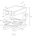
Fig. 1 is a schematic diagram of a plasma cutting apparatus; -
Fig. 2 is a side view of the plasma cutting apparatus shown inFig. 1 -
Fig. 3 is a front view of the plasma cutting apparatus shown inFig. 1 ; -
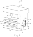
Fig. 4 is a rear view of the plasma cutting apparatus shown inFig. 1 ; -
Fig. 5 is front transparent view of the plasma cutting apparatus shown inFig. 1 showing some internal components; -
Figs. 6A-6B are exemplary views of an automated plasma cutting system; -
Fig. 7 is a front view of the plasma cutting apparatus shown inFig. 1 displaying further features; -
Figs. 8A-8C are detail views of exemplary user interfaces for the plasma cutting apparatus; and -
Figs. 9-11 show another plasma cutting apparatus adapted for connection to a plasma arc source. - Referring to
Figs. 1-8C ,plasma cutting apparatus 10 includes ahousing 12, aworkpiece support 14, amovable plasma nozzle 16, and anozzle drive arrangement 15. Thehousing 12 includes a base 18, anupright pedestal 20 extending upward from the base, and astationary head 22 cantilevered from theupright pedestal 20. Theworkpiece support 14 extends from theupright pedestal 20 and is located below thestationary head 22. Thenozzle 16 extends downward from an underside of thestationary head 22 and is oriented for delivering a cutting plasma generally along one direction (e.g. here vertically downward) and toward a workpiece 101 on theworkpiece support 14. - The
nozzle drive arrangement 15 is mounted to thestationary head 22 and is connected for moving theplasma nozzle 16 during a cutting operation. For example, the nozzles drive arrangement may be up with the head or suspended from the head, or a combination of both. As shown inFig. 5 , the nozzle drive arrangement may be completely enclosed within thehead 22. Thearrangement 15 may take the form of spaced apart rails ortracks 17 and a set of cross rails ortracks 19, where thenozzle 16 is mounted for side-to-side movement on the cross rails or tacks 19 (e.g., under control of a motor, such as a stepper motor, or a linear actuator) and where the cross-rail ortack 19 is mounted for front to back movement along the spaced apart rails or tracks 17 (e.g., under control of a motor, such as a stepper motor, or linear actuator). Movement of theplasma nozzle 16 may be in any direction on the plane of theworkpiece support 14. Thus, if theworkpiece support 14 is viewed as an X-Y plane, thenozzle drive arrangement 15 can position theplasma nozzle 16 at any coordinate of that X-Y plane. - The
nozzle drive arrangement 15 may include means to automatically adjust the nozzle height relative to the workpiece during the cut operation. This is commonly known as torch height control (THC) and several examples are known, one method using voltage sensing feedback. - The height of the workpiece support 14 along the
pedestal 20 is adjustable. In one embodiment this may be accomplished by simply ratcheting the support upward or downward thru one or more indexed notches or supports integral with thepedestal 20. In other embodiments a rack and pinion gear setup may be disposed within thehousing 12 and manually actuated with an external knob or handle 24. Powered height adjustment (e.g., motor or linear actuator) is also possible. - The
housing 12 may include removable cover panel orpanels 25 associated withstationary head 22 that cover and protecthousing 12 components during normal cutting operations but permits infrequent servicing or maintenance of thenozzle drive arrangement 15 and other machine components in the head. - As shown in
Fig. 1 ,plasma cutting apparatus 10 may include acollection pan 26, which may collect cut parts or dust that have passed through openings in theworkpiece support 14 and/or any cooling water used during the cutting process. Thecollection pan 26 may rest on the base 18, suspend from theworkpiece support 14, or mount directly to thepedestal 20. As shown inFig. 7 thecollection pan 26 is removed. - As shown in
Fig. 7 and according to the present invention, a plasma shield is included at the underside of thestationary head 22 and may be disposed around theplasma nozzle 16 along at least front, left, and right side portions of thestationary head 22. InFig. 7 , a partial view of the shielding 28 is shown on the left side portion of thestationary head 22. Thisplasma shield 28 may be tinted so as to not only provide a physical shield around the plasma created for cutting but also an energy shield to help protect the user's eyes. The height of theplasma shield 28 according to the present invention can be raised and lowered to facilitate aligning theplasma nozzle 16 before cutting and for accessing theplasma nozzle 16 for repairing and/or replacing theplasma nozzle 16. Height adjustment may be accomplished byhandle 27. Alternatively, height adjustment may be accomplished by a drive arrangement (e.g., motor or linear actuator) included withinhousing 12 for powered adjustment of the height of theplasma shield 28. - As best shown in
Fig. 4 ,pedestal 20 ofhousing 12 may include various ports for introducing plasma source gas, information, or power into theplasma cutting apparatus 10. These ports may be aggregated as one array or set 32. Exemplary ports include fixed couplers for each of plasma supply gas, voltage, grounding, and system feedback, collectively shown as port set 36. Additional ports may include universalserial bus ports 38 and fixedpower inlet coupler 42. Conveniently, this port set 32 may be included on the rear of theplasma cutting apparatus 10. - Port set 36 provides an inlet for the plasma source gas, voltage, grounding, and system feedback as directly received from the plasma supply. Typical plasma supply outputs for gas and voltage are delivered in one cable to a nozzle, system feedback received in said cable from the nozzle and delivered to a standalone machine controller thru a separate communications cable (e.g. ethernet), and grounding thru a separate wire generally affixed on one end to a clamp. The cable, ethernet, and ground wire may or may not be detachable from the plasma supply. Receipt and communication of these inputs and signals at the cutting
apparatus 10 is dependent on the specific output configurations of the plasma supply. Thus, anexternal harness 103 of hose and wiring is preferred to directly connect the plasma supply to the cuttingapparatus 10 at port set 36. - As shown schematically in
Fig. 5 , anetwork 35 of hose and wiring for delivering plasma supply gas and voltage between port set 36 and thenozzle 16 may be included entirely within thehousing 12 andnozzle 16. At least a portion of thenetwork 35 in thehead 22 may be flexible to facilitate the nozzle movement (e.g., as in a coiled tubular air hose). - Port set 36 may include a gas supply, voltage path, a ground path, and one or more status feedback paths. In this manner, a stand-alone plasma arc power generator 102 can be attached to the
plasma cutting apparatus 10, and signals may be passed between theplasma cutting apparatus 10 and the plasma arc power generator 102 in a direction both from and back to the plasma arc power generator. Thus, using a system of feedback between the two units, an efficient amount of power may be used to generate the cutting plasma. - Multiple plasma supply ground paths may be made available. One preferred location for workpiece 101 grounding is thru the
workpiece support 14. Alternately, a fixed ground path coupler 40 may be provided and used to directly ground the workpiece 101 using a detachable cable and clamp that connects to the coupler 40. Plasma operation is not possible without adequate workpiece grounding, hence providing extensive and redundant grounding paths throughout the cutting apparatus is desired. - As shown in
Figs. 6A-6B , a complete automatedplasma cutting system 200 includes an automatedplasma cutting apparatus 10, a plasma arc power generator 102, and anexternal harness 103 of hose and wiring (schematically shown) for directly connecting and communicating between the plasma cutting apparatus and the plasma arc power generator. The external harness may include one or multiple wires, cables, or hoses depending on the number and types of outputs on the plasma arc power generator 102. Theexternal harness 103 has no direct gas or voltage supply or communication means with thenozzle 16 except thru cuttingapparatus 10 and port set 36.Fig. 6A shows a typical shop environment setup on a conventional workbench whileFig. 6B shows a floor arrangement. - Although the
plasma cutting apparatus 10 may be pre-programmed with basic cutting shapes, as described more fully below, universalserial bus ports 38, 54 may be used to import programming for more complex cutting shapes. In addition, or alternatively,plasma cutting apparatus 10 may also include a wireless network radio for importing such programming. -
Plasma cutting apparatus 10 may also include a user interface 44 on thehousing 12. Conveniently, user interface 44 may be included on the front ofplasma cutting apparatus 10, especially onhead 22, and may be formed by a display 66, switches, buttons, knobs and/or data ports. - As shown in
Fig. 5 ,plasma cutting apparatus 10 includes acontroller 100 within thehousing 12 and connected to control thenozzle drive arrangement 15 andplasma nozzle 16 to control plasma nozzle movement and plasma nozzle firing according to a specified cut pattern to be made in the workpiece 101. As used herein, the term controller is intended to broadly encompass any circuit (e.g., solid state, application specific integrated circuit (ASIC), an electronic circuit, a combinational logic circuit, a field programmable gate array (FPGA)), processor(s) (e.g., shared, dedicated, or group - including hardware or software that executes code), software, firmware and/or other components, or a combination of some or all of the above, that carries out the control functions of the machine or the control functions of any component thereof. The controller may also include locally-stored and accessible non-transitory memory, which incorporates, for example cut patterns (e.g. G-code). The cut patterns may or may not include variable parameters for ready user adjustment via the user interface. - Conveniently, the
controller 100 may be configured to effect operation of thenozzle drive arrangement 15 to carry out an automatic homing operation of the plasma nozzle upon conclusion of a given cutting process. Additionally, the controller may be configured to automatically convert certain drawing formats to G-code for operation of the nozzle drive arrangement and plasma nozzle firing. - As best shown in
Fig. 3 andFigs. 8A-8C , user interface 44 may include multiple selectable standard cut shape inputs. Convenient standard cut shapes may include circles, rectangles (or squares), and lines (or slots). Circles allow for the introduction of holes and can allow theplasma cutting apparatus 10 to replace a standard drill press machine in manufacturing components with holes. The user interface 44 may also includesize adjustment knob 48 to increase the radius of the standard cut circles, the side length of standard cut rectangles, and the length of standard cut lines. Additionally, user interface 44 may includenozzle speed input 50. Optional kerf position adjustment input 52 allows for the toggling of the kerf position, which may be convenient if theplasma cutting apparatus 10 is to be used for producing both cutouts, i.e., the piece removed from the workpiece is retained but the remaining workpiece is discarded, and holes, i.e., the workpiece is retained but the piece removed is discarded. Data input port 54, shown as a universal serial bus port inFig. 3 , may be used for receiving custom cut data, just as the universalserial bus ports 38, described above. Receipt of cut data flash memory of a universal serial bus and/or thru a wifi connection is possible. The user interface 44 may also include anilluminated start button 56 that may be lit with one color to indicate proper grounding and general readiness of theplasma cutting apparatus 10 and may be lit a different color to indicate the cut is in progress. For instance, theilluminated start button 56 may shine in a green color to indicate the apparatus is prepared for cutting and may shine in a red color to indicate the apparatus is performing a cut. - As shown in
Figs. 8A-8C , the user interface 44 may display various pre-programmed configurations.Fig. 8A shows a set of touchscreen selection controls that can be used to select the shape, e.g.,circle 58,slot 60, square 62, andrectangle 64, of the cut.Size adjustment knob 48 may be may be an integral component of the touchscreen, as shown inFig. 8A , but it may also be a stand-alone control, as shown inFig. 3 . The size is selected by rotating the knob until the appropriate dimension is displayed in display 66. Forcircle 58, the displayed value is the radius. For theslot 60, the displayed value is the length. For the square 62, the displayed value is the side length. For therectangle 64, two values are displayed, one for each of the side lengths. Each standard cut shape may have an indicator light associated with it. In one example, the indicator light is shown as one color for the selectedshape 68 and another color for the non-selected shapes 70. -
Fig. 8B shows another option for the user interface 44. Here, touchscreen controls allow for the selection of one of the shapes and standalone controls are then used for controlling the size of these shapes, as shown inFig. 8C . InFig. 8C , the selected shape 72 is shown and size adjustment controls 74 are used to set relevant dimensions. - The starting position on the workpiece to be cut may be aligned using one of many alignment mechanisms. The simplest alignment mechanism may include a laser pointer aimed along the
plasma nozzle 16 and down toward the workpiece 101. Alternatively, the entire outline of the intended cut may be projected onto the workpiece using conventional projection technology. As another alternative, a camera may be installed to view along theplasma nozzle 16, and the image displayed from that camera may include an overlay of the intended cut. Yet another alternative is to align lenses and mirrors to allow the user to operate theplasma cutting apparatus 10 from in front of the apparatus while viewing alignment marks built into the lens on the workpiece 101. - The
plasma cutting apparatus 10 uses fixedpower input coupler 42, shown inFig. 4 , as a means to connect normal source power (either 120V or 240V) from a typical wall-mounted receptacle to theplasma cutting apparatus 10. - Referring to
Fig. 7 , the angle of asegment 16A of thenozzle 16 relative to theworkpiece support 14 may be adjustable to create bevel cuts in a workpiece (not shown). Other potential uses for angling the nozzle include offsetting known draft angles and visible striation patterns due to the cutting process. - A
nozzle 16 comprises typical plasma wear consumables known in the art, such as, but not limited to, tips, electrodes, and swirls rings. A nozzle body can be defined as receiving plasma wear consumables. - In another plasma cutting apparatus,
housing 12 includes aplasma nozzle 16, mounted to deliver a cutting plasma generally along one direction or dimension and to a workpiece 101 on theworkpiece support 14. The housing may also contain a plasmasource conduit network 35, a user interface 44, acontroller 100, and a fixed port set 36 for receiving plasma supply gas, voltage, grounding, and system feedback. The plasmasource conduit network 35 connects the cutting mechanism and the at least one fixed port set 36 and is completely enclosed within the housing and cutting mechanism during operation of the plasma cutting apparatus. - The relative position of the cutting plasma to the
workpiece support 14 can be adjusted in two orthogonal directions of said one direction or dimension, without adjusting the relative positions between theworkpiece support 14,pedestal 20, and top 22. Thus, theworkpiece support 14 may remain stationary during cutting. - Typical machine torch feedback signals include OK-to-move and voltage sensing. These are typically transmitted from the nozzle to the plasma power supply then to a standalone motion controller. The feedback signals and motion controller are self-contained with the cutting apparatus.
- In one embodiment, the area of the projected rectangular footprint of the
head 22 may be at least 70% of the area of the projected rectangular footprint of the base and no more than 130% of the area of the projected rectangular footprint of the base. As used herein the area of the projected rectangular footprint refers to an area determined by multiplying a largest front to back to dimension (of the head or base) by the largest side to side dimension (of the head or base). In the illustrated embodiment, the area of the projected rectangular footprint of the head is substantially the same as the area of the projected rectangular footprint of the base. - It is to be clearly understood that the above description is intended by way of illustration and example only, is not intended to be taken by way of limitation, and that other changes and modifications are possible. For example, a cutting apparatus 110, with base 112, pedestal 114, cantilevered head 116, workpiece support 118,
plasma nozzle 120, shielding 122 and fixedcouplers 124 is shown, with internal set of hose or tube andwiring 126.
Claims (15)
- A plasma cutting apparatus (10; 110), comprising:- a housing (12) comprising a base (18; 112), an upright pedestal (20; 114) extending upward from the base (18; 112) and a stationary head (22; 116) cantilevered from the upright pedestal (20; 114);- a workpiece support (14; 118) extending from the upright pedestal (20; 114) and located below the stationary head (22; 116);- a movable plasma nozzle (16; 120) extending downward from an underside of the stationary head (22; 116) and oriented for delivering a cutting plasma generally along one direction and toward a workpiece (101) on the workpiece support (14; 118); and- a nozzle drive arrangement (15) mounted to the stationary head (22; 116) and connected for moving the plasma nozzle (16; 120) during a cutting operation,characterized by
further including permanent, removable, or deflectable shielding (28; 122) which is included at the underside of the stationary head (22; 116) and adjustable in height for raising and lowering the shielding (28 ; 122) to facilitate aligning of the plasma nozzle (16 ; 120) before cutting and for accessing the plasma nozzle (16 ; 120) for repairing and/or replacing the plasma nozzle (16 ; 120). - The plasma cutting apparatus (10; 110) of claim 1, wherein:- the nozzle drive arrangement (15) is configured to move the plasma nozzle (16; 120) in a first direction substantially perpendicular to the one direction and a second direction substantially perpendicular to both the one direction and the first direction; and- the nozzle drive arrangement (15) is configured to move the plasma nozzle (16; 120) in a third direction substantially parallel to the one direction enabling variance and/or control of nozzle distance from the workpiece (101) during cutting operations.
- The plasma cutting apparatus (10; 110) of claim 1 or 2,
wherein a height of the workpiece support (14; 118) along the pedestal (20; 114) is adjustable. - The plasma cutting apparatus (10; 110) of one of the preceding claims, further comprising a controller (100) within the housing (12) and connected to control the nozzle drive arrangement (15) and plasma nozzle (16; 120) to control plasma nozzle movement and plasma nozzle firing according to a specified cut pattern to be made in a workpiece (101), wherein the controller (100) comprises on-board non-transitory memory storing one or more cut patterns.
- The plasma cutting apparatus (10; 110) of claim 4,
further comprising a user interface (44) on the housing (12),
wherein the user interface (44) includes selectable inputs (58, 60, 62, 64) for accessing locally-stored cut patterns, and/ or
wherein the user interface includes selectable input (50) for nozzle speed and/or selection of automatic nozzle speed adjustment. - The plasma cutting apparatus (10; 110) of claim 5,
wherein the user interface includes selectable inputs (58, 48) for a circular hole cut pattern and a circular hole dimension. - The plasma cutting apparatus (10; 110) of one of the preceding claims, further including one or more data ports configured to receive custom cut pattern information from an external source.
- The plasma cutting apparatus (10; 110) of one of the preceding claims, further including an alignment mechanism.
- The plasma cutting apparatus (10; 110) of one of the preceding claims, wherein an angle of the nozzle tip relative to the workpiece support (14; 118) is adjustable.
- The plasma cutting apparatus (10; 110) of one of the preceding claims, wherein the workpiece support (14; 118) is grounded to a plasma supply ground path.
- The cutting apparatus (10; 110) of one of the preceding claims, further including a removable catch pan (26) below the workpiece support (14; 118).
- The cutting apparatus (10; 110) of one of the preceding claims,
wherein a projected rectangular footprint of the head (22; 116) is at least 70% of an area of the projected rectangular footprint of the base (18; 112) and no more than 130% of the area of the projected rectangular footprint of the base (18; 112). - The plasma cutting apparatus (10; 110) of one of the preceding claims, wherein- the housing (12) comprises one or more fixed couplers (42; 124) for receiving plasma supply gas, plasma voltage, plasma grounding, and plasma system feedback;- a movable nozzle body is mounted on the housing (12) for movement, the movable nozzle body including replaceable wear components;- a network (35) of hose and wiring (126) for transmitting plasma supply gas and plasma voltage is provided between the fixed couplers (42; 124) and the nozzle body, wherein the network (35) of hose and wiring (126) is enclosed within the housing (12) and nozzle body.
- The plasma cutting apparatus (10; 110) of claim 13,
wherein the hose and wiring (126) is completely enclosed within the housing (12) and nozzle body. - A plasma cutting system (200), comprising:- an automated plasma cutting apparatus (10; 110) as defined in one of the preceding claims including a movable plasma nozzle body mounted thereon;- a remote plasma arc power generator (102); and- an external harness (103) of hose and wiring (126) directly connecting and communicating between the plasma cutting apparatus (10; 110) and the plasma arc power generator (102).
Applications Claiming Priority (2)
| Application Number | Priority Date | Filing Date | Title |
|---|---|---|---|
| US201662368249P | 2016-07-29 | 2016-07-29 | |
| PCT/US2017/043600 WO2018022547A1 (en) | 2016-07-29 | 2017-07-25 | Automated plasma cutting apparatus with a housing comprising a movable plasma nozzle, and plasma cutting system |
Publications (2)
| Publication Number | Publication Date |
|---|---|
| EP3490749A1 EP3490749A1 (en) | 2019-06-05 |
| EP3490749B1 true EP3490749B1 (en) | 2020-10-21 |
Family
ID=59569369
Family Applications (1)
| Application Number | Title | Priority Date | Filing Date |
|---|---|---|---|
| EP17749773.2A Not-in-force EP3490749B1 (en) | 2016-07-29 | 2017-07-25 | Automated plasma cutting apparatus with a housing comprising a movable plasma nozzle, and plasma cutting system |
Country Status (4)
| Country | Link |
|---|---|
| US (1) | US10556300B2 (en) |
| EP (1) | EP3490749B1 (en) |
| CN (1) | CN109475967A (en) |
| WO (1) | WO2018022547A1 (en) |
Families Citing this family (9)
| Publication number | Priority date | Publication date | Assignee | Title |
|---|---|---|---|---|
| US10071525B2 (en) * | 2017-02-07 | 2018-09-11 | Thermwood Corporation | Apparatus and method for printing long composite thermoplastic parts on a dual gantry machine during additive manufacturing |
| CN110605467B (en) * | 2019-09-20 | 2020-08-04 | 中国科学院地质与地球物理研究所 | Ion cutting calibration device, calibration method and ion cutting device |
| CN110841408A (en) * | 2019-11-26 | 2020-02-28 | 山西航天清华装备有限责任公司 | Plasma cutting equipment with smoke detection and variable frequency dust removal functions |
| CN112935587A (en) * | 2021-03-29 | 2021-06-11 | 张爱华 | Novel plate laser cutting machine |
| US11618209B1 (en) | 2022-03-24 | 2023-04-04 | Thermwood Corporation | Apparatus and method for depositing material during additive manufacturing |
| US20240286213A1 (en) * | 2023-01-06 | 2024-08-29 | Illinois Tool Works Inc. | Systems and methods for electrochemical machining |
| CN118162730B (en) * | 2024-05-16 | 2024-08-27 | 易通(山东)通风设备有限公司 | Inverter type air plasma cutting machine |
| CN118832269A (en) * | 2024-09-24 | 2024-10-25 | 南通市通州东盛纺织机械有限公司 | Plasma cutting device for calico printing machine |
| CN120306770B (en) * | 2025-06-05 | 2025-12-23 | 无锡诺飞高新技术有限公司 | A plasma cutting device and method for precision stamping die concave dies |
Family Cites Families (38)
| Publication number | Priority date | Publication date | Assignee | Title |
|---|---|---|---|---|
| JPS6046868A (en) | 1983-08-24 | 1985-03-13 | Toyama Hiratsuka Kenkyusho:Kk | Cutting and piercing device utilizing energy of light, electron, gas flame or the like |
| FR2578138B1 (en) * | 1985-02-22 | 1987-03-27 | Soudure Autogene Francaise | PLASMA WELDING OR CUTTING SYSTEM WITH TIMING |
| FR2626206B1 (en) * | 1988-01-25 | 1990-05-18 | Soudure Autogene Francaise | TORCH AND ARC WORKING MACHINE, AND CARTRIDGE THEREFOR |
| JPH0577051A (en) | 1991-09-13 | 1993-03-30 | Komai Tekko Inc | Plasma gouging device |
| US5844196A (en) | 1997-09-15 | 1998-12-01 | The Esab Group, Inc. | System and method for detecting nozzle and electrode wear |
| JP3407857B2 (en) | 1998-02-18 | 2003-05-19 | 日鐵溶接工業株式会社 | Plasma cutting method and apparatus |
| US6359251B1 (en) | 2000-04-10 | 2002-03-19 | Hypertherm, Inc. | Centralized control architecture for a plasma arc system |
| US6772040B1 (en) * | 2000-04-10 | 2004-08-03 | Hypertherm, Inc. | Centralized control architecture for a plasma arc system |
| GB0014725D0 (en) | 2000-06-16 | 2000-08-09 | Contour Cutting Technologies L | Cutting Machine |
| US6486438B1 (en) * | 2000-09-25 | 2002-11-26 | Bore Repair Systems, Inc. | Automated welding device for the buildup of material |
| FR2830476B1 (en) | 2001-10-09 | 2003-12-12 | Soudure Autogene Francaise | METHOD AND INSTALLATION FOR MODULATED PLASMA JET CUTTING AT THE LEVEL OF SUDDEN CHANGES IN THE PATH, ESPECIALLY ANGLES |
| US6745454B1 (en) | 2002-01-30 | 2004-06-08 | Hayes Lemmerz International, Inc. | Flexible manufacturing and workpiece transfer system |
| JP2004351449A (en) | 2003-05-28 | 2004-12-16 | Komatsu Sanki Kk | Plasma cutting device and its controller |
| US7022935B1 (en) * | 2003-12-08 | 2006-04-04 | Illinois Tool Works Inc. | Plasma-cutting torch with integrated high frequency starter |
| WO2006001242A1 (en) | 2004-06-25 | 2006-01-05 | Komatsu Industries Corporation | Multiple thermal cutting device and multiple thermal cutting method |
| CN101934533B (en) * | 2004-11-15 | 2012-07-04 | 西龙公司 | Automatic pattern making apparatus |
| US7709765B2 (en) | 2005-12-28 | 2010-05-04 | Hypertherm, Inc. | Networking architecture for thermal processing system |
| US8350182B2 (en) | 2006-09-11 | 2013-01-08 | Hypertherm, Inc. | Portable autonomous material processing system |
| US8502111B2 (en) | 2007-04-12 | 2013-08-06 | Charles L. Henderson | Laser woodworking machine |
| US9539664B2 (en) * | 2008-06-17 | 2017-01-10 | Matthew Fagan | Methods and systems for predictive torch height control |
| US8450637B2 (en) * | 2008-10-23 | 2013-05-28 | Baker Hughes Incorporated | Apparatus for automated application of hardfacing material to drill bits |
| US8395075B2 (en) * | 2009-05-29 | 2013-03-12 | Kiffer Industries Inc. | Plasma torch cutting device and process |
| US20140061170A1 (en) | 2012-04-04 | 2014-03-06 | Hypertherm, Inc | Identifying Thermal Processing Torch Components |
| US8395074B2 (en) | 2010-12-03 | 2013-03-12 | Kaliburn, Inc. | Plasma ARC systems with cutting and marking functions |
| JP5918985B2 (en) | 2011-12-07 | 2016-05-18 | 株式会社アマダホールディングス | Thermal cutting apparatus and thermal cutting method |
| CN103212895B (en) * | 2012-01-19 | 2016-03-02 | 昆山思拓机器有限公司 | A kind of automatic through hole system for laser cutting nozzle |
| US9395715B2 (en) | 2012-04-04 | 2016-07-19 | Hypertherm, Inc. | Identifying components in a material processing system |
| CN102861976A (en) * | 2012-09-13 | 2013-01-09 | 钟敏 | Automatic plasma welding device for welding of stainless hollow cutter bar |
| CN202824719U (en) * | 2012-09-25 | 2013-03-27 | 昆山尚达智机械有限公司 | Novel bench drill |
| CN202824755U (en) * | 2012-09-25 | 2013-03-27 | 昆山尚达智机械有限公司 | Novel frequency conversion drilling machine |
| CN103170784B (en) * | 2013-03-07 | 2015-11-04 | 广州明珞汽车装备有限公司 | A kind of body in white intelligent positioning system |
| CN203265856U (en) * | 2013-03-25 | 2013-11-06 | 朱晋锋 | Automatic plasma flame cutting machine |
| CN203526786U (en) * | 2013-07-08 | 2014-04-09 | 武汉理工大学 | Automatic plasma built-up welding device for hot-forging die cavity coating |
| US9878392B2 (en) | 2014-02-17 | 2018-01-30 | Lincoln Global, Inc. | System and method for multiverse controls |
| US9604304B2 (en) | 2014-02-21 | 2017-03-28 | Lincoln Global, Inc. | Methods and system for enhanced plasma torch control with an inertial sensor |
| US9446472B2 (en) | 2014-03-05 | 2016-09-20 | Lincoln Global, Inc. | System and method for integrated controller |
| US10486261B2 (en) * | 2014-03-28 | 2019-11-26 | Lincoln Global, Inc. | Plasma system with integrated power supply, motion control, gas control and torch |
| CN105436769A (en) * | 2015-12-25 | 2016-03-30 | 苏州润昇精密机械有限公司 | Small-sized integrated automation laser welding equipment |
-
2017
- 2017-07-25 WO PCT/US2017/043600 patent/WO2018022547A1/en not_active Ceased
- 2017-07-25 EP EP17749773.2A patent/EP3490749B1/en not_active Not-in-force
- 2017-07-25 CN CN201780046620.0A patent/CN109475967A/en active Pending
- 2017-07-25 US US15/658,805 patent/US10556300B2/en active Active
Non-Patent Citations (1)
| Title |
|---|
| None * |
Also Published As
| Publication number | Publication date |
|---|---|
| US10556300B2 (en) | 2020-02-11 |
| WO2018022547A1 (en) | 2018-02-01 |
| US20180029171A1 (en) | 2018-02-01 |
| CN109475967A (en) | 2019-03-15 |
| EP3490749A1 (en) | 2019-06-05 |
Similar Documents
| Publication | Publication Date | Title |
|---|---|---|
| US10556300B2 (en) | Automated plasma cutting apparatus and system | |
| AT507538B1 (en) | METHOD AND DEVICE FOR CONTROLLING THE SIMULATION OF A WELDING PROCESS | |
| DE69620686T2 (en) | LASER PROCESSING MACHINE AND SEWING MACHINE WITH A LASER PROCESSING FUNCTION | |
| EP2973505B1 (en) | Welding training systems and devices | |
| JP5030951B2 (en) | Welding method and system with position determination of welding torch | |
| CN204584547U (en) | A kind of Flat bed laser marking system | |
| EP3127404A1 (en) | Systems and methods for measuring voltage and current in a torch | |
| WO2008131949A2 (en) | Positioning means for producing light signals to position a robot tool relative to a workpiece; method using such positioning means | |
| CN112775541A (en) | Laser cutting equipment for printed circuit board | |
| US10150190B2 (en) | Processing machine line | |
| CN212350764U (en) | Laser cutting equipment for printed circuit board | |
| JP2015199176A (en) | cutting device | |
| JP6085315B2 (en) | Device for cooling shrink-fit chucks | |
| CN102632310B (en) | Automatic brazing equipment | |
| CN207215016U (en) | A kind of vision-based detection and micromatic setting | |
| CN110934389B (en) | A visual wax diamond setting machine | |
| CN220240395U (en) | Single-tube distributing device of automatic feeding laser cutting machine | |
| US20160147216A1 (en) | Apparatus for monitoring and providing visual representations of the operating conditions of machine tool parameters | |
| CN208662811U (en) | A kind of dedicated plasma cutting machine of end carriage cutting | |
| CN210002088U (en) | Steam thermal shrinkage device | |
| CN105643056B (en) | A Welding Method of Discontinuous Lattice Matrix and Core Double-skin Shell Structure | |
| CN221494595U (en) | Laser processing devices and equipment | |
| CN222520383U (en) | Spot welding equipment for instrument case | |
| CN215880393U (en) | Guide rail device of sapphire substrate processing laser etching machine | |
| CN203715895U (en) | Buttonhole maker with hammer adjusting mechanism |
Legal Events
| Date | Code | Title | Description |
|---|---|---|---|
| STAA | Information on the status of an ep patent application or granted ep patent |
Free format text: STATUS: UNKNOWN |
|
| STAA | Information on the status of an ep patent application or granted ep patent |
Free format text: STATUS: THE INTERNATIONAL PUBLICATION HAS BEEN MADE |
|
| PUAI | Public reference made under article 153(3) epc to a published international application that has entered the european phase |
Free format text: ORIGINAL CODE: 0009012 |
|
| STAA | Information on the status of an ep patent application or granted ep patent |
Free format text: STATUS: REQUEST FOR EXAMINATION WAS MADE |
|
| 17P | Request for examination filed |
Effective date: 20190227 |
|
| AK | Designated contracting states |
Kind code of ref document: A1 Designated state(s): AL AT BE BG CH CY CZ DE DK EE ES FI FR GB GR HR HU IE IS IT LI LT LU LV MC MK MT NL NO PL PT RO RS SE SI SK SM TR |
|
| AX | Request for extension of the european patent |
Extension state: BA ME |
|
| DAV | Request for validation of the european patent (deleted) | ||
| DAX | Request for extension of the european patent (deleted) | ||
| GRAP | Despatch of communication of intention to grant a patent |
Free format text: ORIGINAL CODE: EPIDOSNIGR1 |
|
| STAA | Information on the status of an ep patent application or granted ep patent |
Free format text: STATUS: GRANT OF PATENT IS INTENDED |
|
| INTG | Intention to grant announced |
Effective date: 20200529 |
|
| GRAS | Grant fee paid |
Free format text: ORIGINAL CODE: EPIDOSNIGR3 |
|
| GRAA | (expected) grant |
Free format text: ORIGINAL CODE: 0009210 |
|
| STAA | Information on the status of an ep patent application or granted ep patent |
Free format text: STATUS: THE PATENT HAS BEEN GRANTED |
|
| AK | Designated contracting states |
Kind code of ref document: B1 Designated state(s): AL AT BE BG CH CY CZ DE DK EE ES FI FR GB GR HR HU IE IS IT LI LT LU LV MC MK MT NL NO PL PT RO RS SE SI SK SM TR |
|
| REG | Reference to a national code |
Ref country code: GB Ref legal event code: FG4D |
|
| REG | Reference to a national code |
Ref country code: CH Ref legal event code: EP |
|
| REG | Reference to a national code |
Ref country code: DE Ref legal event code: R096 Ref document number: 602017025904 Country of ref document: DE |
|
| REG | Reference to a national code |
Ref country code: IE Ref legal event code: FG4D |
|
| REG | Reference to a national code |
Ref country code: AT Ref legal event code: REF Ref document number: 1325341 Country of ref document: AT Kind code of ref document: T Effective date: 20201115 |
|
| REG | Reference to a national code |
Ref country code: AT Ref legal event code: MK05 Ref document number: 1325341 Country of ref document: AT Kind code of ref document: T Effective date: 20201021 |
|
| REG | Reference to a national code |
Ref country code: NL Ref legal event code: MP Effective date: 20201021 |
|
| PG25 | Lapsed in a contracting state [announced via postgrant information from national office to epo] |
Ref country code: NO Free format text: LAPSE BECAUSE OF FAILURE TO SUBMIT A TRANSLATION OF THE DESCRIPTION OR TO PAY THE FEE WITHIN THE PRESCRIBED TIME-LIMIT Effective date: 20210121 Ref country code: PT Free format text: LAPSE BECAUSE OF FAILURE TO SUBMIT A TRANSLATION OF THE DESCRIPTION OR TO PAY THE FEE WITHIN THE PRESCRIBED TIME-LIMIT Effective date: 20210222 Ref country code: RS Free format text: LAPSE BECAUSE OF FAILURE TO SUBMIT A TRANSLATION OF THE DESCRIPTION OR TO PAY THE FEE WITHIN THE PRESCRIBED TIME-LIMIT Effective date: 20201021 Ref country code: GR Free format text: LAPSE BECAUSE OF FAILURE TO SUBMIT A TRANSLATION OF THE DESCRIPTION OR TO PAY THE FEE WITHIN THE PRESCRIBED TIME-LIMIT Effective date: 20210122 Ref country code: FI Free format text: LAPSE BECAUSE OF FAILURE TO SUBMIT A TRANSLATION OF THE DESCRIPTION OR TO PAY THE FEE WITHIN THE PRESCRIBED TIME-LIMIT Effective date: 20201021 |
|
| REG | Reference to a national code |
Ref country code: LT Ref legal event code: MG4D |
|
| PG25 | Lapsed in a contracting state [announced via postgrant information from national office to epo] |
Ref country code: ES Free format text: LAPSE BECAUSE OF FAILURE TO SUBMIT A TRANSLATION OF THE DESCRIPTION OR TO PAY THE FEE WITHIN THE PRESCRIBED TIME-LIMIT Effective date: 20201021 Ref country code: AT Free format text: LAPSE BECAUSE OF FAILURE TO SUBMIT A TRANSLATION OF THE DESCRIPTION OR TO PAY THE FEE WITHIN THE PRESCRIBED TIME-LIMIT Effective date: 20201021 Ref country code: BG Free format text: LAPSE BECAUSE OF FAILURE TO SUBMIT A TRANSLATION OF THE DESCRIPTION OR TO PAY THE FEE WITHIN THE PRESCRIBED TIME-LIMIT Effective date: 20210121 Ref country code: IS Free format text: LAPSE BECAUSE OF FAILURE TO SUBMIT A TRANSLATION OF THE DESCRIPTION OR TO PAY THE FEE WITHIN THE PRESCRIBED TIME-LIMIT Effective date: 20210221 Ref country code: LV Free format text: LAPSE BECAUSE OF FAILURE TO SUBMIT A TRANSLATION OF THE DESCRIPTION OR TO PAY THE FEE WITHIN THE PRESCRIBED TIME-LIMIT Effective date: 20201021 Ref country code: PL Free format text: LAPSE BECAUSE OF FAILURE TO SUBMIT A TRANSLATION OF THE DESCRIPTION OR TO PAY THE FEE WITHIN THE PRESCRIBED TIME-LIMIT Effective date: 20201021 Ref country code: SE Free format text: LAPSE BECAUSE OF FAILURE TO SUBMIT A TRANSLATION OF THE DESCRIPTION OR TO PAY THE FEE WITHIN THE PRESCRIBED TIME-LIMIT Effective date: 20201021 |
|
| PG25 | Lapsed in a contracting state [announced via postgrant information from national office to epo] |
Ref country code: NL Free format text: LAPSE BECAUSE OF FAILURE TO SUBMIT A TRANSLATION OF THE DESCRIPTION OR TO PAY THE FEE WITHIN THE PRESCRIBED TIME-LIMIT Effective date: 20201021 Ref country code: HR Free format text: LAPSE BECAUSE OF FAILURE TO SUBMIT A TRANSLATION OF THE DESCRIPTION OR TO PAY THE FEE WITHIN THE PRESCRIBED TIME-LIMIT Effective date: 20201021 |
|
| REG | Reference to a national code |
Ref country code: DE Ref legal event code: R097 Ref document number: 602017025904 Country of ref document: DE |
|
| PG25 | Lapsed in a contracting state [announced via postgrant information from national office to epo] |
Ref country code: SK Free format text: LAPSE BECAUSE OF FAILURE TO SUBMIT A TRANSLATION OF THE DESCRIPTION OR TO PAY THE FEE WITHIN THE PRESCRIBED TIME-LIMIT Effective date: 20201021 Ref country code: RO Free format text: LAPSE BECAUSE OF FAILURE TO SUBMIT A TRANSLATION OF THE DESCRIPTION OR TO PAY THE FEE WITHIN THE PRESCRIBED TIME-LIMIT Effective date: 20201021 Ref country code: SM Free format text: LAPSE BECAUSE OF FAILURE TO SUBMIT A TRANSLATION OF THE DESCRIPTION OR TO PAY THE FEE WITHIN THE PRESCRIBED TIME-LIMIT Effective date: 20201021 Ref country code: LT Free format text: LAPSE BECAUSE OF FAILURE TO SUBMIT A TRANSLATION OF THE DESCRIPTION OR TO PAY THE FEE WITHIN THE PRESCRIBED TIME-LIMIT Effective date: 20201021 Ref country code: CZ Free format text: LAPSE BECAUSE OF FAILURE TO SUBMIT A TRANSLATION OF THE DESCRIPTION OR TO PAY THE FEE WITHIN THE PRESCRIBED TIME-LIMIT Effective date: 20201021 Ref country code: EE Free format text: LAPSE BECAUSE OF FAILURE TO SUBMIT A TRANSLATION OF THE DESCRIPTION OR TO PAY THE FEE WITHIN THE PRESCRIBED TIME-LIMIT Effective date: 20201021 |
|
| PLBE | No opposition filed within time limit |
Free format text: ORIGINAL CODE: 0009261 |
|
| STAA | Information on the status of an ep patent application or granted ep patent |
Free format text: STATUS: NO OPPOSITION FILED WITHIN TIME LIMIT |
|
| PG25 | Lapsed in a contracting state [announced via postgrant information from national office to epo] |
Ref country code: DK Free format text: LAPSE BECAUSE OF FAILURE TO SUBMIT A TRANSLATION OF THE DESCRIPTION OR TO PAY THE FEE WITHIN THE PRESCRIBED TIME-LIMIT Effective date: 20201021 |
|
| 26N | No opposition filed |
Effective date: 20210722 |
|
| PG25 | Lapsed in a contracting state [announced via postgrant information from national office to epo] |
Ref country code: IT Free format text: LAPSE BECAUSE OF FAILURE TO SUBMIT A TRANSLATION OF THE DESCRIPTION OR TO PAY THE FEE WITHIN THE PRESCRIBED TIME-LIMIT Effective date: 20201021 Ref country code: AL Free format text: LAPSE BECAUSE OF FAILURE TO SUBMIT A TRANSLATION OF THE DESCRIPTION OR TO PAY THE FEE WITHIN THE PRESCRIBED TIME-LIMIT Effective date: 20201021 |
|
| PG25 | Lapsed in a contracting state [announced via postgrant information from national office to epo] |
Ref country code: SI Free format text: LAPSE BECAUSE OF FAILURE TO SUBMIT A TRANSLATION OF THE DESCRIPTION OR TO PAY THE FEE WITHIN THE PRESCRIBED TIME-LIMIT Effective date: 20201021 |
|
| REG | Reference to a national code |
Ref country code: DE Ref legal event code: R119 Ref document number: 602017025904 Country of ref document: DE |
|
| REG | Reference to a national code |
Ref country code: CH Ref legal event code: PL |
|
| GBPC | Gb: european patent ceased through non-payment of renewal fee |
Effective date: 20210725 |
|
| PG25 | Lapsed in a contracting state [announced via postgrant information from national office to epo] |
Ref country code: MC Free format text: LAPSE BECAUSE OF FAILURE TO SUBMIT A TRANSLATION OF THE DESCRIPTION OR TO PAY THE FEE WITHIN THE PRESCRIBED TIME-LIMIT Effective date: 20201021 |
|
| REG | Reference to a national code |
Ref country code: BE Ref legal event code: MM Effective date: 20210731 |
|
| PG25 | Lapsed in a contracting state [announced via postgrant information from national office to epo] |
Ref country code: LI Free format text: LAPSE BECAUSE OF NON-PAYMENT OF DUE FEES Effective date: 20210731 Ref country code: GB Free format text: LAPSE BECAUSE OF NON-PAYMENT OF DUE FEES Effective date: 20210725 Ref country code: CH Free format text: LAPSE BECAUSE OF NON-PAYMENT OF DUE FEES Effective date: 20210731 Ref country code: DE Free format text: LAPSE BECAUSE OF NON-PAYMENT OF DUE FEES Effective date: 20220201 |
|
| PG25 | Lapsed in a contracting state [announced via postgrant information from national office to epo] |
Ref country code: IS Free format text: LAPSE BECAUSE OF FAILURE TO SUBMIT A TRANSLATION OF THE DESCRIPTION OR TO PAY THE FEE WITHIN THE PRESCRIBED TIME-LIMIT Effective date: 20210221 Ref country code: LU Free format text: LAPSE BECAUSE OF NON-PAYMENT OF DUE FEES Effective date: 20210725 Ref country code: FR Free format text: LAPSE BECAUSE OF NON-PAYMENT OF DUE FEES Effective date: 20210731 |
|
| PG25 | Lapsed in a contracting state [announced via postgrant information from national office to epo] |
Ref country code: IE Free format text: LAPSE BECAUSE OF NON-PAYMENT OF DUE FEES Effective date: 20210725 Ref country code: BE Free format text: LAPSE BECAUSE OF NON-PAYMENT OF DUE FEES Effective date: 20210731 |
|
| PG25 | Lapsed in a contracting state [announced via postgrant information from national office to epo] |
Ref country code: CY Free format text: LAPSE BECAUSE OF FAILURE TO SUBMIT A TRANSLATION OF THE DESCRIPTION OR TO PAY THE FEE WITHIN THE PRESCRIBED TIME-LIMIT Effective date: 20201021 |
|
| PG25 | Lapsed in a contracting state [announced via postgrant information from national office to epo] |
Ref country code: HU Free format text: LAPSE BECAUSE OF FAILURE TO SUBMIT A TRANSLATION OF THE DESCRIPTION OR TO PAY THE FEE WITHIN THE PRESCRIBED TIME-LIMIT; INVALID AB INITIO Effective date: 20170725 |
|
| PG25 | Lapsed in a contracting state [announced via postgrant information from national office to epo] |
Ref country code: MK Free format text: LAPSE BECAUSE OF FAILURE TO SUBMIT A TRANSLATION OF THE DESCRIPTION OR TO PAY THE FEE WITHIN THE PRESCRIBED TIME-LIMIT Effective date: 20201021 |
|
| PG25 | Lapsed in a contracting state [announced via postgrant information from national office to epo] |
Ref country code: TR Free format text: LAPSE BECAUSE OF FAILURE TO SUBMIT A TRANSLATION OF THE DESCRIPTION OR TO PAY THE FEE WITHIN THE PRESCRIBED TIME-LIMIT Effective date: 20201021 |
|
| PG25 | Lapsed in a contracting state [announced via postgrant information from national office to epo] |
Ref country code: MT Free format text: LAPSE BECAUSE OF FAILURE TO SUBMIT A TRANSLATION OF THE DESCRIPTION OR TO PAY THE FEE WITHIN THE PRESCRIBED TIME-LIMIT Effective date: 20201021 |