EP3490668B1 - Vorrichtung zur therapeutischen behandlung von gewebeverletzungen - Google Patents
Vorrichtung zur therapeutischen behandlung von gewebeverletzungen Download PDFInfo
- Publication number
- EP3490668B1 EP3490668B1 EP17761575.4A EP17761575A EP3490668B1 EP 3490668 B1 EP3490668 B1 EP 3490668B1 EP 17761575 A EP17761575 A EP 17761575A EP 3490668 B1 EP3490668 B1 EP 3490668B1
- Authority
- EP
- European Patent Office
- Prior art keywords
- applicator
- electric
- tissue injury
- electric signal
- air
- Prior art date
- Legal status (The legal status is an assumption and is not a legal conclusion. Google has not performed a legal analysis and makes no representation as to the accuracy of the status listed.)
- Active
Links
- 208000037816 tissue injury Diseases 0.000 title claims description 52
- 238000011282 treatment Methods 0.000 title claims description 20
- 230000001225 therapeutic effect Effects 0.000 title claims description 16
- 230000005684 electric field Effects 0.000 claims description 34
- QVGXLLKOCUKJST-UHFFFAOYSA-N atomic oxygen Chemical compound [O] QVGXLLKOCUKJST-UHFFFAOYSA-N 0.000 claims description 28
- 229910052760 oxygen Inorganic materials 0.000 claims description 28
- 239000001301 oxygen Substances 0.000 claims description 28
- CBENFWSGALASAD-UHFFFAOYSA-N Ozone Chemical compound [O-][O+]=O CBENFWSGALASAD-UHFFFAOYSA-N 0.000 claims description 27
- 239000003990 capacitor Substances 0.000 claims description 5
- 238000004519 manufacturing process Methods 0.000 claims description 5
- 125000006850 spacer group Chemical group 0.000 claims description 3
- 230000009471 action Effects 0.000 claims description 2
- 239000012141 concentrate Substances 0.000 claims 1
- 230000009466 transformation Effects 0.000 claims 1
- 230000000694 effects Effects 0.000 description 16
- 210000001519 tissue Anatomy 0.000 description 14
- 208000027418 Wounds and injury Diseases 0.000 description 11
- 230000006378 damage Effects 0.000 description 11
- 208000014674 injury Diseases 0.000 description 10
- 238000000034 method Methods 0.000 description 9
- 210000004027 cell Anatomy 0.000 description 7
- 210000003491 skin Anatomy 0.000 description 7
- 230000004048 modification Effects 0.000 description 5
- 238000012986 modification Methods 0.000 description 5
- 241000894006 Bacteria Species 0.000 description 4
- 230000001413 cellular effect Effects 0.000 description 4
- 230000004098 cellular respiration Effects 0.000 description 4
- 230000007420 reactivation Effects 0.000 description 4
- 241001661918 Bartonia Species 0.000 description 3
- 241000233866 Fungi Species 0.000 description 3
- 241000700605 Viruses Species 0.000 description 3
- 230000006851 antioxidant defense Effects 0.000 description 3
- 239000008280 blood Substances 0.000 description 3
- 210000004369 blood Anatomy 0.000 description 3
- 238000006243 chemical reaction Methods 0.000 description 3
- 239000003795 chemical substances by application Substances 0.000 description 3
- 230000002255 enzymatic effect Effects 0.000 description 3
- 230000035876 healing Effects 0.000 description 3
- 244000045947 parasite Species 0.000 description 3
- 206010017533 Fungal infection Diseases 0.000 description 2
- 208000031888 Mycoses Diseases 0.000 description 2
- 230000033228 biological regulation Effects 0.000 description 2
- 230000001684 chronic effect Effects 0.000 description 2
- 230000003247 decreasing effect Effects 0.000 description 2
- 230000002708 enhancing effect Effects 0.000 description 2
- 239000012530 fluid Substances 0.000 description 2
- 235000013305 food Nutrition 0.000 description 2
- 239000007789 gas Substances 0.000 description 2
- 150000002632 lipids Chemical class 0.000 description 2
- 239000012811 non-conductive material Substances 0.000 description 2
- 230000002093 peripheral effect Effects 0.000 description 2
- 230000003389 potentiating effect Effects 0.000 description 2
- 230000008569 process Effects 0.000 description 2
- 230000002829 reductive effect Effects 0.000 description 2
- 238000007920 subcutaneous administration Methods 0.000 description 2
- 239000000126 substance Substances 0.000 description 2
- 230000002195 synergetic effect Effects 0.000 description 2
- KIUKXJAPPMFGSW-DNGZLQJQSA-N (2S,3S,4S,5R,6R)-6-[(2S,3R,4R,5S,6R)-3-Acetamido-2-[(2S,3S,4R,5R,6R)-6-[(2R,3R,4R,5S,6R)-3-acetamido-2,5-dihydroxy-6-(hydroxymethyl)oxan-4-yl]oxy-2-carboxy-4,5-dihydroxyoxan-3-yl]oxy-5-hydroxy-6-(hydroxymethyl)oxan-4-yl]oxy-3,4,5-trihydroxyoxane-2-carboxylic acid Chemical compound CC(=O)N[C@H]1[C@H](O)O[C@H](CO)[C@@H](O)[C@@H]1O[C@H]1[C@H](O)[C@@H](O)[C@H](O[C@H]2[C@@H]([C@@H](O[C@H]3[C@@H]([C@@H](O)[C@H](O)[C@H](O3)C(O)=O)O)[C@H](O)[C@@H](CO)O2)NC(C)=O)[C@@H](C(O)=O)O1 KIUKXJAPPMFGSW-DNGZLQJQSA-N 0.000 description 1
- PLIKAWJENQZMHA-UHFFFAOYSA-N 4-aminophenol Chemical compound NC1=CC=C(O)C=C1 PLIKAWJENQZMHA-UHFFFAOYSA-N 0.000 description 1
- 200000000007 Arterial disease Diseases 0.000 description 1
- OKTJSMMVPCPJKN-UHFFFAOYSA-N Carbon Chemical compound [C] OKTJSMMVPCPJKN-UHFFFAOYSA-N 0.000 description 1
- 241000588722 Escherichia Species 0.000 description 1
- 241001134654 Lactobacillus leichmannii Species 0.000 description 1
- 241000186779 Listeria monocytogenes Species 0.000 description 1
- WHXSMMKQMYFTQS-UHFFFAOYSA-N Lithium Chemical compound [Li] WHXSMMKQMYFTQS-UHFFFAOYSA-N 0.000 description 1
- 208000006735 Periostitis Diseases 0.000 description 1
- 208000004210 Pressure Ulcer Diseases 0.000 description 1
- 208000028990 Skin injury Diseases 0.000 description 1
- 210000000577 adipose tissue Anatomy 0.000 description 1
- 210000003484 anatomy Anatomy 0.000 description 1
- 230000015572 biosynthetic process Effects 0.000 description 1
- 210000004204 blood vessel Anatomy 0.000 description 1
- 210000000988 bone and bone Anatomy 0.000 description 1
- 229910052799 carbon Inorganic materials 0.000 description 1
- 230000000747 cardiac effect Effects 0.000 description 1
- 210000000845 cartilage Anatomy 0.000 description 1
- 210000000170 cell membrane Anatomy 0.000 description 1
- 231100000749 chronicity Toxicity 0.000 description 1
- 230000006835 compression Effects 0.000 description 1
- 238000007906 compression Methods 0.000 description 1
- 239000004020 conductor Substances 0.000 description 1
- 210000002808 connective tissue Anatomy 0.000 description 1
- 239000000470 constituent Substances 0.000 description 1
- 238000001816 cooling Methods 0.000 description 1
- 210000004207 dermis Anatomy 0.000 description 1
- 230000005672 electromagnetic field Effects 0.000 description 1
- 210000002615 epidermis Anatomy 0.000 description 1
- 229920002674 hyaluronan Polymers 0.000 description 1
- 229960003160 hyaluronic acid Drugs 0.000 description 1
- 230000000415 inactivating effect Effects 0.000 description 1
- 230000002779 inactivation Effects 0.000 description 1
- 230000002401 inhibitory effect Effects 0.000 description 1
- 230000002262 irrigation Effects 0.000 description 1
- 238000003973 irrigation Methods 0.000 description 1
- 230000002045 lasting effect Effects 0.000 description 1
- 230000000670 limiting effect Effects 0.000 description 1
- 229910052744 lithium Inorganic materials 0.000 description 1
- 239000000463 material Substances 0.000 description 1
- 229910052751 metal Inorganic materials 0.000 description 1
- 239000002184 metal Substances 0.000 description 1
- 230000004089 microcirculation Effects 0.000 description 1
- 230000000877 morphologic effect Effects 0.000 description 1
- 210000003205 muscle Anatomy 0.000 description 1
- 238000006213 oxygenation reaction Methods 0.000 description 1
- 206010033675 panniculitis Diseases 0.000 description 1
- 230000036961 partial effect Effects 0.000 description 1
- 230000001575 pathological effect Effects 0.000 description 1
- 230000035515 penetration Effects 0.000 description 1
- 210000003460 periosteum Anatomy 0.000 description 1
- 230000035699 permeability Effects 0.000 description 1
- 229920000642 polymer Polymers 0.000 description 1
- 230000002035 prolonged effect Effects 0.000 description 1
- 230000000638 stimulation Effects 0.000 description 1
- 210000004304 subcutaneous tissue Anatomy 0.000 description 1
- 238000003786 synthesis reaction Methods 0.000 description 1
- 210000002435 tendon Anatomy 0.000 description 1
- 230000017423 tissue regeneration Effects 0.000 description 1
- 208000037997 venous disease Diseases 0.000 description 1
- 238000010792 warming Methods 0.000 description 1
Images


Classifications
-
- A—HUMAN NECESSITIES
- A61—MEDICAL OR VETERINARY SCIENCE; HYGIENE
- A61N—ELECTROTHERAPY; MAGNETOTHERAPY; RADIATION THERAPY; ULTRASOUND THERAPY
- A61N1/00—Electrotherapy; Circuits therefor
- A61N1/02—Details
- A61N1/04—Electrodes
- A61N1/0404—Electrodes for external use
- A61N1/0408—Use-related aspects
- A61N1/0468—Specially adapted for promoting wound healing
-
- A—HUMAN NECESSITIES
- A61—MEDICAL OR VETERINARY SCIENCE; HYGIENE
- A61N—ELECTROTHERAPY; MAGNETOTHERAPY; RADIATION THERAPY; ULTRASOUND THERAPY
- A61N1/00—Electrotherapy; Circuits therefor
- A61N1/44—Applying ionised fluids
-
- A—HUMAN NECESSITIES
- A61—MEDICAL OR VETERINARY SCIENCE; HYGIENE
- A61M—DEVICES FOR INTRODUCING MEDIA INTO, OR ONTO, THE BODY; DEVICES FOR TRANSDUCING BODY MEDIA OR FOR TAKING MEDIA FROM THE BODY; DEVICES FOR PRODUCING OR ENDING SLEEP OR STUPOR
- A61M35/00—Devices for applying media, e.g. remedies, on the human body
-
- A—HUMAN NECESSITIES
- A61—MEDICAL OR VETERINARY SCIENCE; HYGIENE
- A61N—ELECTROTHERAPY; MAGNETOTHERAPY; RADIATION THERAPY; ULTRASOUND THERAPY
- A61N1/00—Electrotherapy; Circuits therefor
- A61N1/02—Details
- A61N1/04—Electrodes
- A61N1/0404—Electrodes for external use
- A61N1/0472—Structure-related aspects
- A61N1/0476—Array electrodes (including any electrode arrangement with more than one electrode for at least one of the polarities)
-
- A—HUMAN NECESSITIES
- A61—MEDICAL OR VETERINARY SCIENCE; HYGIENE
- A61N—ELECTROTHERAPY; MAGNETOTHERAPY; RADIATION THERAPY; ULTRASOUND THERAPY
- A61N1/00—Electrotherapy; Circuits therefor
- A61N1/18—Applying electric currents by contact electrodes
- A61N1/32—Applying electric currents by contact electrodes alternating or intermittent currents
- A61N1/36—Applying electric currents by contact electrodes alternating or intermittent currents for stimulation
- A61N1/36014—External stimulators, e.g. with patch electrodes
-
- A—HUMAN NECESSITIES
- A61—MEDICAL OR VETERINARY SCIENCE; HYGIENE
- A61M—DEVICES FOR INTRODUCING MEDIA INTO, OR ONTO, THE BODY; DEVICES FOR TRANSDUCING BODY MEDIA OR FOR TAKING MEDIA FROM THE BODY; DEVICES FOR PRODUCING OR ENDING SLEEP OR STUPOR
- A61M37/00—Other apparatus for introducing media into the body; Percutany, i.e. introducing medicines into the body by diffusion through the skin
- A61M2037/0007—Other apparatus for introducing media into the body; Percutany, i.e. introducing medicines into the body by diffusion through the skin having means for enhancing the permeation of substances through the epidermis, e.g. using suction or depression, electric or magnetic fields, sound waves or chemical agents
-
- A—HUMAN NECESSITIES
- A61—MEDICAL OR VETERINARY SCIENCE; HYGIENE
- A61M—DEVICES FOR INTRODUCING MEDIA INTO, OR ONTO, THE BODY; DEVICES FOR TRANSDUCING BODY MEDIA OR FOR TAKING MEDIA FROM THE BODY; DEVICES FOR PRODUCING OR ENDING SLEEP OR STUPOR
- A61M2202/00—Special media to be introduced, removed or treated
- A61M2202/02—Gases
- A61M2202/0216—Ozone
-
- A—HUMAN NECESSITIES
- A61—MEDICAL OR VETERINARY SCIENCE; HYGIENE
- A61M—DEVICES FOR INTRODUCING MEDIA INTO, OR ONTO, THE BODY; DEVICES FOR TRANSDUCING BODY MEDIA OR FOR TAKING MEDIA FROM THE BODY; DEVICES FOR PRODUCING OR ENDING SLEEP OR STUPOR
- A61M2205/00—General characteristics of the apparatus
- A61M2205/05—General characteristics of the apparatus combined with other kinds of therapy
- A61M2205/054—General characteristics of the apparatus combined with other kinds of therapy with electrotherapy
Definitions
- the present invention relates to an apparatus for the therapeutic treatment of tissue injuries.
- Skin injuries variably deep, are areas of tissue breakage and loss with exposure of the underlying tissues.
- the term "external injury” or “wound” indicates the morphological and functional destruction of the continuity of the superficial skin layers and, in the most severe cases, of the deep subcutaneous ones.
- the injuries are evaluated and catalogued according to their amplitude, depth and characteristics.
- the mild superficial injuries affect only the epidermis, the dermis, and at most a part of the hypoderm; the deepest and most severe ones involve all the subcutaneous tissue (adipose tissue) up to the muscles, the periosteum, causing the exposure of bone or support structures (tendons and cartilages); the most severe (chronic) ones are characterized by loss of substance at skin level and poor healing tendency.
- Typical tissue injuries are, for example, pressure injuries (or decubitus ulcers), which are commonly referred to as "sores”.
- the sores are the direct consequence of a high or prolonged compression, or of cutting forces (or stretching), causing a mechanical stress to the tissues and shrinkage of blood vessels.
- regenotherapy which, to accelerate tissue reconstruction, uses a radio frequency signal between 1MHz and 400MHz transmitted by suitable antennas with limited signal strength (0.15 mW) to affect tissues.
- the effect is to improve the cellular respiration and to accelerate the cellular exchange, resulting in the reconstruction of the tissue affected by the injury.
- the signal produced by the instrument through which regenotherapy is performed causes a modification of the permeability of the cytoplasmic membrane with resulting electrolytic re-balancing. Where a pathological failure exists, the application of these defined radio frequency signals causes an internal and external re-balancing to the cell.
- the regenotherapy exerts good effects on connective tissue and venous and arterial diseases of all kinds, wherein it was determined that controlled electromagnetic fields force the synthesis of hyaluronic acid, a basic constituent of connective substance and pericapillary sleeve.
- US 2014/0200506 and WO 2013/040542 disclose a method of treating a fungal infection wherein an electrode is placed proximate an anatomical region of interest having a fungal infection and an electric field or a plasma is applied on the region of interest.
- US 2015/327963 discloses an electrical discharge irrigation device comprising a center electrode and a return electrode; the device creates electrical discharge between the center and return electrodes.
- US 2015/216816 discloses a treatment method for improved cooling of lipid-rich tissue and a system for non-invasively removing heat from subcutaneous lipid-rich target areas of a patient; the system includes an applicator and can comprise a return electrode located separately from the applicator. Power line can electrically connect the return electrode and the energy-generating unit.
- the object of the present invention is to provide an innovative apparatus for enhancing the effects of current therapeutic treatment techniques for tissue injuries.
- this object is achieved with an apparatus for the therapeutic treatment of a tissue injury as defined in claim 1.
- Figure 1 schematically shows an apparatus 1, according to the present invention, for the therapeutic treatment of a tissue injury.
- the apparatus 1 substantially comprises a control unit 2 through which to operate the apparatus 1, by adjusting at least one parameter, and an applicator 3 adapted to be positioned in proximity of the tissue injury to be treated, said applicator 3 being in fluid and in electric connection with the control unit 2.
- connection of applicator 3 to the control unit 2 is configured by means of a connecting tube 4 for air or oxygen passage and at least an electric cable 5 for the electric connection.
- the control unit 2 is configured to generate, at applicator 3, an electric field to be applied to the tissue injury and to generate also an air or oxygen flow which is converted into ozone still at said applicator 3 to be diffused and applied to the tissue injury along with said electric field, synergistically enhancing the therapeutic effect.
- control unit 2 comprises an electric power supply 6 adapted to convert the mains voltage (with alternating waveform, maximum value 220 V and frequency 50 Hz) to a continuous supply voltage, such as at 12-13 V.
- the power can be supplied directly from a lithium polymer rechargeable battery 7.
- the electric power supply 6, or the batteries 7, provide electric power to at least one electric pump 8 adapted to generate an air or oxygen flow which, through the connecting tube 4, is sent to applicator 3.
- the electric pump 8 is provided with a first regulator 80 by means of which it is possible to start, modify its flow rate, or stop the air or oxygen flow conveyed to applicator 3.
- control unit 2 comprises an oscillator 9 for generating a first electric signal S1 with a rectangular waveform having a frequency of between 500-5000 Hz, a maximum current value of about 50 mA and a maximum voltage value of between 12-13 V.
- the first electric signal S1 is amplified by a power stage 10 (e.g., a FET) placed downstream of oscillator 9.
- a second electric signal S2 will therefore be provided at the output to the power stage 10, again with a rectangular waveform at the same frequency as the first electric signal S1 with a current value of about 3 A and a maximum voltage value of approximately 100 V.
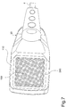
- applicator 3 ( Fig. 2 ) provides for a diffuser 11 in which the air or oxygen from the pump 8 is conveyed through the connection tube 4.
- the diffuser 11 comprises a bottom grid 19 ( Fig. 4 ) of a non-conductive material adapted to diffuse air or oxygen, so that these gases may affect a larger area.
- a high voltage generator 21 housed and embedded in a high-dielectric rigidity plastic cylinder.
- the high voltage generator 21 comprises a transformer 15 connected to the power stage 10 by means of the electric cable 5 and having in input the second electric signal S2.
- the transformer 15 has the function of modifying the voltage and the current of the second electric signal S2, by providing a third electric signal S3 in output with a sawtooth waveform, with a maximum voltage value of about 10 KV, with a value of current of about 0.5 mA and which maintains the frequency value of the second electric signal S2.
- the high voltage generator 21 comprises a voltage multiplier 16 ( Figs. 1 , 2 ) comprising a plurality of diode-capacitor multiplier cells.
- the voltage multiplier 16 comprises 6 multiplier cells.
- the voltage multiplier 16 is adapted to receive said third electric signal S3 and to provide a fourth electric output signal S4 which is rectified and is equal to the maximum value of the third electric signal S3 multiplied by the number of diode-capacitor multiplier cells present in the voltage multiplier 16 (in this case multiplied by 6).
- the voltage value of the fourth electric signal S4, which, as said, is a continuous signal is about 6-60 KV.
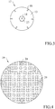
- the fourth electric signal S4 is supplied to an electrode 17 by means of a screw stem 22 placed below and in electric connection with the high voltage generator 21, said electrode 17 being also present within applicator 3 and adapted to generate said electric field to be applied to the tissue injury.
- the electrode 17 is placed internally to the diffuser 11 ( Fig. 2 ) and comprises a conductive plate 13 with a central hole through which the screw stem 22 is inserted in contact, and also includes a plurality of sharp conductive elements 18 extending from the same conductive plate 13 ( Fig. 3 ).
- the sharp conductive elements 18 are arranged along a circumference on a lower side of the conductive plate 13, they are mutually equidistant and also substantially radially directed, i.e., each sharp conductor 18 has a given inclination relative to the perpendicular to the plane of the conductive plate 13.
- a locking nut 23 (self-locking or blind) adapted to screw on said screw stem 22 is present, and centrally having itself a further sharp conductive element 18.
- the grid 19 is placed in front of the sharp conductive elements 18 at a safety distance of about 55-60 mm in such a way as to avoid the direct contact of the sharp conductive elements 18 with the patient, but especially to apply a suitable value electric field to the tissue injury, considering that the dielectric strength of the humid air is about 1 KV/mm.
- a plurality of pins 20 of about 5 mm in length may be present on the surface 13 of the grid 19 ( Fig. 2 ), said pins 20 being adapted to contact the patient's skin in proximity of the tissue injury, avoiding the direct contact of the grid 19 with the tissue injury.
- the pins 20 are arranged along a circumference in the outer portion of the grid 19, so that they can contact the skin on healthy areas, externally surrounding the tissue injury to be treated.
- the grid 19 includes 8 pins 20.
- the electrode 17 is at a high electric potential (6-60 KV). In this high potential condition, the charge density tends to be higher in the sharp portion of each conductive element 18 (for the phenomenon known as "dispersing power of the tips"), producing an electric field at the tips that is greater than in the rest of the electrode 17.
- a second regulator it is possible to modify the electric field by varying the electric potential of the electrode 17.
- the high electric field of the tips causes ionization of the air or oxygen flow which is conveyed within the diffuser 11, triggering a plurality of electric discharges (the so-called “crown effect") starting from the sharp part of each of the conductive elements 18.
- the modification of the electric potential applied to the electrode 17 results in an increase or a decrease in the electric discharges generated by the crown effect; specifically, the electric discharges increase as the electric potential increases on the electrode 17.
- a return electrode (not shown in Figs. 1-5 ), electrically connected through an electric cable 12 to a reference potential VI, for example 100 milliVolt, and applied to the patient via, e.g., a patch in a position near to the tissue injury, and the arrangement of applicator 3 on the tissue injury allows to convey the electric discharges generated by the conductive elements 18 on the tissue injury.
- a reference potential VI for example 100 milliVolt
- the passage of air or oxygen conveyed within the diffuser 11 by the electric discharges causes the production of ozone, according to the chemical reaction 3 O 2 ⁇ 2 O 3 . Therefore, the modification of the electric potential applied to the electrode 17 also has the effect of increasing or decreasing the ozone concentration (the emitted ozone concentration becomes greater as the electric potential increases over the electrode 17), concentration which can also be modified by adjusting the air or oxygen flow generated by the electric pump 8.
- applicator 3 may comprise an ultraviolet (UV) lamp instead of the circuit structure constituted by the high voltage generator 21 and electrode 17.
- UV ultraviolet
- the above chemical reaction for ozone production from air or oxygen in this case is carried out at the passage of the oxygen in front of the UV lamp (185 nm), each molecule of oxygen disintegrating and then recombining into three atoms, generating ozone.
- the apparatus 1 is used to treat tissue injuries, such as pressure injuries, which are commonly referred to as "sores". Unlike the known apparatuses, said apparatus 1 is more effective, since its operation synergically combines the effects of both the electric field and the ozone, both affecting the tissue injury. This results in an enhancement of the therapeutic effect due to the combined action of the electric field and ozone.
- the electric field has the effect of improving the cellular respiration and accelerating the cellular exchange, resulting in the reconstruction of the tissue affected by the injury.
- the ozone has the effect of improving the blood ability to bring oxygen to the tissues, resulting in the reactivation of microcirculation and peripheral oxygenation, stimulation of the reactivation of the enzymatic antioxidant defense systems of the organism, and it is a powerful agent against bacteria, fungi, viruses and parasites.
- the apparatus 1 is adjustable by means of a timer for the automatic shutdown of the control unit 2 at the end of a set time.
- the apparatus 1 may include a support (not shown in the Figures) comprising a base, an adjustable height vertical rod extending from said base and an adjustable arm rotatably pivoted to said rod. At the free end of the adjustable arm there is a junction to which applicator 3 is connected, said support being studied in such a way as to allow the user to reach any area of the patient's body to be treated therapeutically.
- applicator 3 is positioned in proximity of the area to be treated i.e. on the tissue injury.
- the optimum distance of applicator 3 is determined by the distance of the grid 19 from the electrode 17 and from the pins 20 which, by contacting the patient's skin in the areas adjacent to the injury, on one hand, do not cause the patient suffering, and on the other hand, maximize the effectiveness of treatment on the injury, ( Fig. 5 ); the applicator is therefore contacted with the patient's skin.
- the electric pump 8 When operated, the electric pump 8 generates an air or oxygen flow that may be controlled by said first regulator 80, to increase or decrease the ozone concentration which is intended to be produced.
- the air or oxygen flow generated by the electric pump 8 flows through the connecting tube 4 and is collected and conveyed within the diffuser 11.
- the apparatus 1 generates at the sharp conductive elements 18 a high electric field which is adjustable through said second regulator, modifying the electric potential applied over the electrode 17.
- the return electrode is advantageously positioned in contact with the patient, so that the electric field primarily affects the area of the tissue injury and then discharges over the return electrode.
- the effect of the electric field is to improve the cellular respiration and accelerate the cellular exchange, resulting in the reconstruction of the injured tissue.
- the electric field also causes the ionisation of the air or oxygen flow conveyed within the diffuser 11, triggering electric discharges that, starting from the sharp conductive elements 18 of the electrode 17, discharge in the direction of the return electrode.
- Such electric discharges transform the air or oxygen flow conveyed within the diffuser 11 into an ozone flow, with a concentration determined also by the regulation through the second potential regulator on the electrode 17.
- the ozone flow is diffused and directed to the tissue injury and, as said, has the effect of improving the blood ability to bring oxygen to tissues, stimulate the reactivation of the enzymatic antioxidant defense systems of the organism, and is a very potent agent against bacteria, fungi, viruses and parasites.
- the treatment provides for daily sessions, each of 15-30 minutes, depending on the case.
- the contraindications are the usual ones for devices using electric fields: therefore, they should not be used in the case of patients with cardiac pacemakers, pregnant women, patients with metal prostheses in proximity of the area to be treated.
- Figures 6-9 illustrate an apparatus for the therapeutic treatment of a tissue injury according to a second embodiment of the present invention.
- the apparatus of Figs. 6-9 differs from the apparatus of Figs. 1-5 only for the different type of applicator 30 used and since the control unit 2 is adapted to convey within applicator 30 only an air flow and not an oxygen flow.
- Said applicator 30 is in fluid and in electric connection with the control unit 2.
- the connection of applicator 30 to the control unit 2 is carried out by means of the connecting tube 4 for the passage of air and the electric cable 5 for the electric connection.
- Applicator 30, better shown in Fig. 7-9 includes a diffuser 110 wherein the air from the electric pump 8 is conveyed through the connecting tube 4.
- the diffuser 110 includes a bottom grid 190 ( Figure 8 and 9 ) of a non-conductive material adapted to diffuse air or oxygen, so that these gases may affect a larger area.
- a transformer 150 connected to the power stage 10 by means of the electric cable 5 is present and having the second electric signal S2 in input.
- Transformer 150 has the function of modifying the voltage and the current of the second electric signal S2, providing a third electric signal S3 in output with a sawtooth waveform, with a maximum voltage value of about 5 KV, with a current value of about 10 mA and which maintains the frequency value of the second electric signal S2.
- a voltage multiplier 160 is present ( Figures 8 and 9 ), which in turn comprises a plurality of diode-capacitor multiplier cells.
- the voltage multiplier 160 comprises 8 multiplier cells.
- the voltage multiplier 160 is adapted to receive the third electric signal S3 and to provide a fourth electric signal S4 in output which is rectified and is equal to the maximum value of the third electric signal S3 multiplied by the diode-capacitor multiplier cells present in the voltage multiplier 160 (in this case multiplied by 12).
- the voltage value of the fourth electric signal S4, which, as said, is a continuous signal is about 6-60 KV.
- the fourth electric signal S4 is provided to an electrode 170 adapted to generate the electric field to be applied on the tissue injury; electrode 170 is connected to a dividing wall 171 adapted to separate the zone of applicator 30 which contains the voltage multiplier 160 and transformer 150 from the area of the diffuser 110 which comprises electrode 170 and two tubes 41 which extend from the tube 4.
- Electrode 170 is placed internally within the diffuser 110 and includes a cylindrical element 130 of a plastic material from which a plurality of threadlike conductive elements 180, preferably carbon-based, are provided, from which a plurality of electric discharges 400 are generated.
- the applicator is configured to convey said electric discharges to the grid 190; in fact, the threadlike conductive elements 180 are arranged so that the generated electric field invades the whole grid 190, as shown in Figure 9 .
- the grid 190 is placed in front of the threadlike conductive elements 180 at a safety distance of about 60-65 mm in such a way as to avoid the direct contact of the threadlike conductive elements 180 with the patient, but especially to apply a suitable value electric field on the tissue injury, considering that the dielectric strength of the humid air is about 1 KV/mm.
- a disposable annular spacer element 200 having a thickness of about 5 mm and preferably a depth of 12 mm and preferably a length of 420 mm, is placed on the peripheral part 130 of the grid 190 to avoid direct contact of the grid 190 with the tissue injury to externally surround the tissue injury to be treated.
- electrode 170 is at a high electric potential (6-60 KV), the charge density tends to be greater in the free end of each threadlike conductive element 180 (for the phenomenon known as "dispersing power of the tips"), producing an electric field at the free ends which is greater than in the rest of electrode 170.
- a regulator it is possible to modify the electric field by varying the electric potential of electrode 170.
- the high electric field of the tips causes the ionization of the air flow which is conveyed within the diffuser 110, triggering a plurality of electric discharges (the so-called “crown effect") from the free ends of each of the conductive elements 180.
- the modification of the electric potential applied to electrode 170 results in an increase or a decrease in the electric discharges generated by the crown effect; specifically, the electric discharges increase as the electric potential increases on electrode 170.
- the presence of the return electrode 120 ( Figure 6 ), electrically connected through an electric cable 12 to a reference potential VI, for example 10 milliVolt, and applied to the patient via, e.g. a patch in a position near to the tissue injury, and the arrangement of applicator 30 on the tissue injury allow to convey the electric discharges generated by the conductive elements 180 on the tissue injury.
- a reference potential VI for example 10 milliVolt
- the modification of the electric potential applied to electrode 170 has also the effect of increasing or decreasing the ozone concentration (the emitted ozone concentration becomes greater as the electric potential increases over electrode 170), concentration which can also be modified by adjusting the air flow generated by the electric pump 8.
- applicator 30 is positioned on the area to be treated so that the annular spacer element 200 is in contact with the skin of the patient or user.
- the electric pump 8 When operated in the working position ( Figure 9 ), the electric pump 8 generates an air flow that can be controlled by a first regulator 80, to increase or decrease the ozone concentration to be produced.
- the air flow generated by the electric pump 8 flows through the connecting tube 4 and is collected and conveyed within the diffuser 110 by the tubes 41.
- the apparatus 1 generates, at the conductive elements 180, a high electric field which is adjustable through a second regulator, modifying the electric potential applied to electrode 170.
- the return electrode 120 is placed in contact with the patient, in such a way that the electric field primarily affects the area of the tissue injury and then discharges to the return electrode.
- the effect of the electric field is to improve the cellular respiration and accelerate the cellular exchange, resulting in the reconstruction of the injured tissue.
- the electric field also causes the ionisation of the flow of air conveyed within the diffuser 110, triggering the electric discharges that, starting from the threadlike conductive members 180 of electrode 170, discharge, through the patient, to the return electrode 120.
- Such electric discharges transform the air flow conveyed within the diffuser 110 into an ozone flow, with a concentration also determined by regulation through the second regulator of the potential on electrode 170.
- the ozone flow is diffused and directed to the tissue injury and, as said, has the effect of improving the blood ability to bring oxygen to the tissues, stimulate the reactivation of the enzymatic antioxidant defense systems of the organism, and is a potent agent against bacteria, fungi, viruses and parasites.
- a LED belt 301 is provided, whose ignition indicates the good operation of the apparatus according to the invention, and a transparent cover 300 for protecting the LED belt 301.
- a mobile support structure 500 is provided for the apparatus according to the invention, as can be seen in Fig. 6 .
- the support structure 500 comprises a tray 501 for supporting the unit 2, a height adjustable, also telescopically, vertical rod 503 to which the tray 501 is connected, an arm 502, preferably telescopic, rotatably pivoted to said rod 503 in one end and rotatably pivoted to applicator 30 in the other end.
- the treatment provides for daily sessions, each of 15-30 minutes, depending on the case.
Landscapes
- Health & Medical Sciences (AREA)
- Life Sciences & Earth Sciences (AREA)
- Public Health (AREA)
- Engineering & Computer Science (AREA)
- Biomedical Technology (AREA)
- Veterinary Medicine (AREA)
- Animal Behavior & Ethology (AREA)
- General Health & Medical Sciences (AREA)
- Radiology & Medical Imaging (AREA)
- Nuclear Medicine, Radiotherapy & Molecular Imaging (AREA)
- Heart & Thoracic Surgery (AREA)
- Biophysics (AREA)
- Anesthesiology (AREA)
- Hematology (AREA)
- Electrotherapy Devices (AREA)
- Steroid Compounds (AREA)
Claims (7)
- Vorrichtung (1) zur therapeutischen Behandlung einer Gewebeverletzung eines Nutzers, mit einer Steuereinheit (2), an die ein Applikator (3, 30) angeschlossen ist, der in der Nähe der zu behandelnden Gewebeverletzung positioniert werden kann, wobei die Steuereinheit (2) dazu ausgebildet ist, an dem Applikator (3, 30) ein elektrisches Feld zu generieren, das an die Gewebeverletzung angelegt werden kann,
wobei die Vorrichtung (1) dadurch gekennzeichnet ist, dass sie eine Gegenelektrode aufweist, die mit einem Referenzpotential (V1) elektrisch verbunden ist und an den Nutzer in der Nähe der zu behandelnden Gewebeverletzung angelegt wird, wobei der Applikator auf der Gewebeverletzung platziert wird, um das elektrische Feld auf die Gewebeverletzung zu konzentrieren, und wobei die Steuereinheit (2) auch dazu ausgebildet ist, einen Luft- oder Sauerstoffstrom zu erzeugen, der zu dem Applikator (3, 30) gerichtet ist, und dazu ausgebildet ist, an dem Applikator (3, 30) den Luft- oder Sauerstoffstrom in einen Ozonfluss umzuwandeln, der dazu ausgelegt ist, diffundiert und in kombinierter Wirkung mit dem elektrischen Feld auf die Gewebeverletzung aufgebracht zu werden, wobei der Applikator eine Elektrode (170) aufweist, die mit der Steuereinheit elektrisch verbunden ist, wobei die Elektrode eine Mehrzahl von fadenartigen leitfähigen Elementen (180) aufweist, wobei die fadenartigen leitfähigen Elemente (180) dazu ausgebildet sind, an ihren freien Enden eine Vielzahl von elektrischen Entladungen (400) auszulösen, wobei der Applikator derart ausgebildet ist, dass er die elektrischen Entladungen zu der Gewebeverletzung überträgt, wobei die elektrischen Entladungen (400) dazu ausgebildet sind, den ins Innere des Diffusors (110) beförderten Luftstrom zur Erzeugung des Ozonflusses zu ionisieren. - Vorrichtung (1) nach Anspruch 1,
dadurch gekennzeichnet, dass die Steuereinheit (2) mindestens eine elektrische Pumpe (8) aufweist, die zur Erzeugung des Luft- oder Sauerstoffstroms ausgebildet ist, der durch ein Verbindungsrohr (4) zu dem Applikator (3, 30) geleitet wird, wobei die elektrische Pumpe (8) mit einem ersten Regler (80) versehen ist, mit dessen Hilfe der zu dem Applikator (3, 30) geleitete Luft- oder Sauerstoffstrom und folglich die Konzentration des erzeugten Ozonflusses gestartet, modifiziert oder gestoppt werden kann. - Vorrichtung (1) nach Anspruch 2, dadurch gekennzeichnet,
dass der Applikator (3, 30) einen Diffusor (11, 110) aufweist, der zum Sammeln des Luft- oder Sauerstoffstroms ausgebildet ist, der von der elektrischen Pumpe (8) erzeugt wird und durch das Verbindungsrohr (4) angekommen ist, wobei der Diffusor (11, 110) ein Bodengitter (19, 190) zum Diffundieren des Ozonflusses aufweist, der durch die Umwandlung des darin beförderten Luft- und Sauerstoffstroms erzielt wird. - Vorrichtung 1 nach Anspruch 1,
dadurch gekennzeichnet, dass die Steuereinheit (2) Folgendes aufweist:- einen Oszillator (9), der zum Generieren eines ersten elektrischen Signal (S1) mit einer Rechteck-Wellenform mit einer bestimmten Frequenz ausgebildet ist,- eine Leistungsstufe (10), die stromabwärts von dem Oszillator (9) angeordnet ist und dazu ausgebildet ist, das erste elektrische Signal (S1) zu verstärken und ein zweites elektrisches Signal (S2) wiederum mit einer Rechteck-Wellenform abzugeben;und dass der Applikator (3, 30) Folgendes aufweist:- einen Transformator (150), der mit der Leistungsstufe (10) verbunden ist und an dessen Eingang das zweite elektrische Signal (S2) anliegt, wobei der Transformator (150) dazu ausgebildet ist, die Spannung und den Strom des zweiten elektrischen Signals (S2) zu ändern und am Ausgang ein drittes elektrisches Signal (S3) mit einer Sägezahn-Wellenform zu liefern, das die Frequenz des zweiten elektrischen Signals (S2) beibehält, sowie einen Spannungvervielfacher (160) mit einer Mehrzahl von Dioden-Kondensator-Multiplikatorzellen, wobei der Spannungsvervielfacher (160) dazu ausgebildet ist, das dritte elektrische Signal (S3) zu empfangen und am Ausgang ein viertes gleichgerichtetes elektrisches Signal (S4) bereitzustellen, das gleich dem Maximalwert des dritten Signals multipliziert mit den Multiplikatorzellen ist, die in dem Spannungsvervielfacher (160) vorhanden sind,- wobei die Elektrode (170), an die das vierte elektrische Signal (S4) angelegt wird, zum Generieren des elektrischen Feldes und zur Ionisierung des in den Diffusor (11) beförderten Luft- oder Sauerstoffstroms zur Erzeugung des Ozonflusses ausgebildet ist. - Vorrichtung (1) nach Anspruch 3,
dadurch gekennzeichnet, dass das Gitter (190) ein ringförmiges Abstandselement (200) aufweist, das dazu ausgebildet ist, mit der Haut des Nutzers in der Nähe der Gewebeverletzung in Berührung zu treten, wobei ein direkter Kontakt des Gitters (190) mit der Gewebeverletzung vermieden wird. - Vorrichtung (1) nach Anspruch 3,
dadurch gekennzeichnet, dass das Gitter (190) eine Mehrzahl von Stiften (20) aufweist, die dazu ausgebildet sind, mit der Haut des Nutzers in der Nähe der Gewebeverletzung in Berührung zu treten, wobei ein direkter Kontakt des Gitters (190) mit der Gewebeverletzung vermieden wird. - Vorrichtung (1) nach Anspruch 1,
dadurch gekennzeichnet, dass sie eine bewegliche Stützstruktur (500) bereitstellt, die Folgendes aufweist:- eine Ablage (501) zum Abstützen der Steuereinheit,- eine in der Höhe einstellbare vertikale Stange (503), mit der die Ablage verbunden ist,- einen verstellbaren Arm (502), der an einem Ende an der Stange drehbar angelenkt ist und am anderen Ende mit dem Applikator (30) drehbar in Eingriff steht.
Applications Claiming Priority (2)
| Application Number | Priority Date | Filing Date | Title |
|---|---|---|---|
| IT102016000080827A IT201600080827A1 (it) | 2016-08-01 | 2016-08-01 | Apparato e metodo per il trattamento terapeutico di lesioni tissutali. |
| PCT/IB2017/054493 WO2018025118A1 (en) | 2016-08-01 | 2017-07-25 | Apparatus for therapeutic treatment of tissue injuries |
Publications (2)
| Publication Number | Publication Date |
|---|---|
| EP3490668A1 EP3490668A1 (de) | 2019-06-05 |
| EP3490668B1 true EP3490668B1 (de) | 2021-03-17 |
Family
ID=57851148
Family Applications (1)
| Application Number | Title | Priority Date | Filing Date |
|---|---|---|---|
| EP17761575.4A Active EP3490668B1 (de) | 2016-08-01 | 2017-07-25 | Vorrichtung zur therapeutischen behandlung von gewebeverletzungen |
Country Status (5)
| Country | Link |
|---|---|
| US (1) | US11033730B2 (de) |
| EP (1) | EP3490668B1 (de) |
| ES (1) | ES2877452T3 (de) |
| IT (1) | IT201600080827A1 (de) |
| WO (1) | WO2018025118A1 (de) |
Family Cites Families (13)
| Publication number | Priority date | Publication date | Assignee | Title |
|---|---|---|---|---|
| US5975090A (en) * | 1998-09-29 | 1999-11-02 | Sharper Image Corporation | Ion emitting grooming brush |
| US6810288B2 (en) * | 2001-07-06 | 2004-10-26 | Ceramatec, Inc. | Device and method for wound healing and infection control |
| US7933648B2 (en) * | 2005-07-21 | 2011-04-26 | Naim Erturk Tanrisever | High voltage transcutaneous electrical stimulation device and method |
| KR101292268B1 (ko) * | 2011-08-29 | 2013-08-01 | 한림대학교 산학협력단 | 병렬 구동 마이크로 플라즈마 창상 치료 장치 |
| US20140200506A1 (en) * | 2011-09-17 | 2014-07-17 | M.O.E. Medical Devices Llc | Systems, methods and machine readable programs for electric field and/or plasma-assisted onychomycosis treatment |
| EP3199201A1 (de) * | 2011-09-17 | 2017-08-02 | Moe Medical Devices LLC | Vorrichtung für elektische feld und/oder plasma unterstützt onychomycosis behandlung |
| JP6200508B2 (ja) * | 2012-09-11 | 2017-09-20 | アメリカン イーグル インストラメンツ インコーポレイテッドAmerican Eagle Instruments, Inc. | 放電洗浄器装置および方法 |
| US10266802B2 (en) * | 2013-01-16 | 2019-04-23 | Orteron (T.O) Ltd. | Method for controlling biological processes in microorganisms |
| WO2014143412A1 (en) * | 2013-03-13 | 2014-09-18 | Devicearm, Inc. | Method and apparatus for antimicrobial treatment |
| GB2517729A (en) * | 2013-08-29 | 2015-03-04 | Ozonica Ltd | Disinfection of packaged articles |
| DE102013113905A1 (de) * | 2013-12-12 | 2015-06-18 | Reinhausen Plasma Gmbh | Anordnung zur Behandlung von Wunden |
| ES2974899T3 (es) | 2014-01-31 | 2024-07-02 | Zeltiq Aesthetics Inc | Composiciones y sistemas de tratamiento para el enfriamiento mejorado de tejido rico en lípidos |
| BR112018069044A2 (pt) * | 2016-03-22 | 2019-01-29 | Koninklijke Philips Nv | dispositivo de plasma frio para tratamento da pele |
-
2016
- 2016-08-01 IT IT102016000080827A patent/IT201600080827A1/it unknown
-
2017
- 2017-07-25 US US16/322,540 patent/US11033730B2/en active Active
- 2017-07-25 EP EP17761575.4A patent/EP3490668B1/de active Active
- 2017-07-25 WO PCT/IB2017/054493 patent/WO2018025118A1/en unknown
- 2017-07-25 ES ES17761575T patent/ES2877452T3/es active Active
Non-Patent Citations (1)
| Title |
|---|
| None * |
Also Published As
| Publication number | Publication date |
|---|---|
| US20190184154A1 (en) | 2019-06-20 |
| US11033730B2 (en) | 2021-06-15 |
| ES2877452T3 (es) | 2021-11-16 |
| IT201600080827A1 (it) | 2018-02-01 |
| EP3490668A1 (de) | 2019-06-05 |
| WO2018025118A1 (en) | 2018-02-08 |
Similar Documents
| Publication | Publication Date | Title |
|---|---|---|
| CN107582235B (zh) | 用于增强粘膜组织复原的美容设备 | |
| KR101686783B1 (ko) | 저온 플라즈마를 이용한 휴대용 피부 미용기 | |
| Tiktinsky et al. | Electrotherapy: yesterday, today and tomorrow | |
| US20070038275A1 (en) | High-frequency electrotherapy apparatus | |
| US11517757B2 (en) | Non-therma plasma device with electromagnetic compatibility control | |
| US20180140824A1 (en) | Non-thermal plasma device | |
| US20100099942A1 (en) | Method and apparatus for electromagnetic human and animal immune stimulation and/or repair systems activation | |
| WO2020219517A3 (en) | Electrical stimulation for cancer treatment with internal and external electrodes | |
| EP3453425A1 (de) | Diathermiebehandlungsvorrichtung | |
| KR100649935B1 (ko) | 고주파 전기 발모기 | |
| KR200355189Y1 (ko) | 고주파 전기치료기 | |
| EP3490668B1 (de) | Vorrichtung zur therapeutischen behandlung von gewebeverletzungen | |
| US9821168B2 (en) | Medical bioelectric plasma beam | |
| KR102566702B1 (ko) | 음이온을 이용한 미용장치 | |
| US8287475B2 (en) | Apparatus and method for applying an electrostatic field to a wound or scar to promote healing thereof | |
| US9775995B2 (en) | Treating skin ulcers | |
| KR20240105841A (ko) | 플라즈마 치료기 | |
| KR20140011177A (ko) | 벨트형 단극성 타입 고주파 치료기 | |
| WO2022265837A1 (en) | Methods of using a plasma-generated stream of no-containing gas for treatment of a spectrum of medical conditions | |
| Wandke et al. | DBD-CAP | |
| EP3130373A1 (de) | Vorrichtung zur stimulation der produktion von stickoxid im menschlichen körper | |
| KR20210150757A (ko) | 고주파 온열 치료기 | |
| RU2526427C2 (ru) | Способ электротерапии | |
| EP2578266B1 (de) | Elektro-medizinisches Hochfrequenzgerät | |
| KR950010921A (ko) | 저주파 전기치료기 |
Legal Events
| Date | Code | Title | Description |
|---|---|---|---|
| STAA | Information on the status of an ep patent application or granted ep patent |
Free format text: STATUS: UNKNOWN |
|
| STAA | Information on the status of an ep patent application or granted ep patent |
Free format text: STATUS: THE INTERNATIONAL PUBLICATION HAS BEEN MADE |
|
| PUAI | Public reference made under article 153(3) epc to a published international application that has entered the european phase |
Free format text: ORIGINAL CODE: 0009012 |
|
| STAA | Information on the status of an ep patent application or granted ep patent |
Free format text: STATUS: REQUEST FOR EXAMINATION WAS MADE |
|
| 17P | Request for examination filed |
Effective date: 20190228 |
|
| AK | Designated contracting states |
Kind code of ref document: A1 Designated state(s): AL AT BE BG CH CY CZ DE DK EE ES FI FR GB GR HR HU IE IS IT LI LT LU LV MC MK MT NL NO PL PT RO RS SE SI SK SM TR |
|
| AX | Request for extension of the european patent |
Extension state: BA ME |
|
| DAV | Request for validation of the european patent (deleted) | ||
| DAX | Request for extension of the european patent (deleted) | ||
| GRAP | Despatch of communication of intention to grant a patent |
Free format text: ORIGINAL CODE: EPIDOSNIGR1 |
|
| STAA | Information on the status of an ep patent application or granted ep patent |
Free format text: STATUS: GRANT OF PATENT IS INTENDED |
|
| INTG | Intention to grant announced |
Effective date: 20201020 |
|
| GRAS | Grant fee paid |
Free format text: ORIGINAL CODE: EPIDOSNIGR3 |
|
| GRAA | (expected) grant |
Free format text: ORIGINAL CODE: 0009210 |
|
| STAA | Information on the status of an ep patent application or granted ep patent |
Free format text: STATUS: THE PATENT HAS BEEN GRANTED |
|
| AK | Designated contracting states |
Kind code of ref document: B1 Designated state(s): AL AT BE BG CH CY CZ DE DK EE ES FI FR GB GR HR HU IE IS IT LI LT LU LV MC MK MT NL NO PL PT RO RS SE SI SK SM TR |
|
| REG | Reference to a national code |
Ref country code: GB Ref legal event code: FG4D |
|
| REG | Reference to a national code |
Ref country code: CH Ref legal event code: EP |
|
| REG | Reference to a national code |
Ref country code: DE Ref legal event code: R096 Ref document number: 602017034810 Country of ref document: DE |
|
| REG | Reference to a national code |
Ref country code: IE Ref legal event code: FG4D |
|
| REG | Reference to a national code |
Ref country code: AT Ref legal event code: REF Ref document number: 1371683 Country of ref document: AT Kind code of ref document: T Effective date: 20210415 |
|
| REG | Reference to a national code |
Ref country code: NL Ref legal event code: FP |
|
| REG | Reference to a national code |
Ref country code: LT Ref legal event code: MG9D |
|
| PG25 | Lapsed in a contracting state [announced via postgrant information from national office to epo] |
Ref country code: NO Free format text: LAPSE BECAUSE OF FAILURE TO SUBMIT A TRANSLATION OF THE DESCRIPTION OR TO PAY THE FEE WITHIN THE PRESCRIBED TIME-LIMIT Effective date: 20210617 Ref country code: HR Free format text: LAPSE BECAUSE OF FAILURE TO SUBMIT A TRANSLATION OF THE DESCRIPTION OR TO PAY THE FEE WITHIN THE PRESCRIBED TIME-LIMIT Effective date: 20210317 Ref country code: GR Free format text: LAPSE BECAUSE OF FAILURE TO SUBMIT A TRANSLATION OF THE DESCRIPTION OR TO PAY THE FEE WITHIN THE PRESCRIBED TIME-LIMIT Effective date: 20210618 Ref country code: FI Free format text: LAPSE BECAUSE OF FAILURE TO SUBMIT A TRANSLATION OF THE DESCRIPTION OR TO PAY THE FEE WITHIN THE PRESCRIBED TIME-LIMIT Effective date: 20210317 Ref country code: BG Free format text: LAPSE BECAUSE OF FAILURE TO SUBMIT A TRANSLATION OF THE DESCRIPTION OR TO PAY THE FEE WITHIN THE PRESCRIBED TIME-LIMIT Effective date: 20210617 |
|
| REG | Reference to a national code |
Ref country code: AT Ref legal event code: MK05 Ref document number: 1371683 Country of ref document: AT Kind code of ref document: T Effective date: 20210317 |
|
| PG25 | Lapsed in a contracting state [announced via postgrant information from national office to epo] |
Ref country code: LV Free format text: LAPSE BECAUSE OF FAILURE TO SUBMIT A TRANSLATION OF THE DESCRIPTION OR TO PAY THE FEE WITHIN THE PRESCRIBED TIME-LIMIT Effective date: 20210317 Ref country code: RS Free format text: LAPSE BECAUSE OF FAILURE TO SUBMIT A TRANSLATION OF THE DESCRIPTION OR TO PAY THE FEE WITHIN THE PRESCRIBED TIME-LIMIT Effective date: 20210317 Ref country code: SE Free format text: LAPSE BECAUSE OF FAILURE TO SUBMIT A TRANSLATION OF THE DESCRIPTION OR TO PAY THE FEE WITHIN THE PRESCRIBED TIME-LIMIT Effective date: 20210317 |
|
| PG25 | Lapsed in a contracting state [announced via postgrant information from national office to epo] |
Ref country code: CZ Free format text: LAPSE BECAUSE OF FAILURE TO SUBMIT A TRANSLATION OF THE DESCRIPTION OR TO PAY THE FEE WITHIN THE PRESCRIBED TIME-LIMIT Effective date: 20210317 Ref country code: EE Free format text: LAPSE BECAUSE OF FAILURE TO SUBMIT A TRANSLATION OF THE DESCRIPTION OR TO PAY THE FEE WITHIN THE PRESCRIBED TIME-LIMIT Effective date: 20210317 Ref country code: LT Free format text: LAPSE BECAUSE OF FAILURE TO SUBMIT A TRANSLATION OF THE DESCRIPTION OR TO PAY THE FEE WITHIN THE PRESCRIBED TIME-LIMIT Effective date: 20210317 Ref country code: AT Free format text: LAPSE BECAUSE OF FAILURE TO SUBMIT A TRANSLATION OF THE DESCRIPTION OR TO PAY THE FEE WITHIN THE PRESCRIBED TIME-LIMIT Effective date: 20210317 Ref country code: SM Free format text: LAPSE BECAUSE OF FAILURE TO SUBMIT A TRANSLATION OF THE DESCRIPTION OR TO PAY THE FEE WITHIN THE PRESCRIBED TIME-LIMIT Effective date: 20210317 |
|
| REG | Reference to a national code |
Ref country code: ES Ref legal event code: FG2A Ref document number: 2877452 Country of ref document: ES Kind code of ref document: T3 Effective date: 20211116 |
|
| PG25 | Lapsed in a contracting state [announced via postgrant information from national office to epo] |
Ref country code: SK Free format text: LAPSE BECAUSE OF FAILURE TO SUBMIT A TRANSLATION OF THE DESCRIPTION OR TO PAY THE FEE WITHIN THE PRESCRIBED TIME-LIMIT Effective date: 20210317 Ref country code: PT Free format text: LAPSE BECAUSE OF FAILURE TO SUBMIT A TRANSLATION OF THE DESCRIPTION OR TO PAY THE FEE WITHIN THE PRESCRIBED TIME-LIMIT Effective date: 20210719 Ref country code: PL Free format text: LAPSE BECAUSE OF FAILURE TO SUBMIT A TRANSLATION OF THE DESCRIPTION OR TO PAY THE FEE WITHIN THE PRESCRIBED TIME-LIMIT Effective date: 20210317 Ref country code: RO Free format text: LAPSE BECAUSE OF FAILURE TO SUBMIT A TRANSLATION OF THE DESCRIPTION OR TO PAY THE FEE WITHIN THE PRESCRIBED TIME-LIMIT Effective date: 20210317 Ref country code: IS Free format text: LAPSE BECAUSE OF FAILURE TO SUBMIT A TRANSLATION OF THE DESCRIPTION OR TO PAY THE FEE WITHIN THE PRESCRIBED TIME-LIMIT Effective date: 20210717 |
|
| REG | Reference to a national code |
Ref country code: DE Ref legal event code: R097 Ref document number: 602017034810 Country of ref document: DE |
|
| PLBE | No opposition filed within time limit |
Free format text: ORIGINAL CODE: 0009261 |
|
| STAA | Information on the status of an ep patent application or granted ep patent |
Free format text: STATUS: NO OPPOSITION FILED WITHIN TIME LIMIT |
|
| PG25 | Lapsed in a contracting state [announced via postgrant information from national office to epo] |
Ref country code: DK Free format text: LAPSE BECAUSE OF FAILURE TO SUBMIT A TRANSLATION OF THE DESCRIPTION OR TO PAY THE FEE WITHIN THE PRESCRIBED TIME-LIMIT Effective date: 20210317 Ref country code: AL Free format text: LAPSE BECAUSE OF FAILURE TO SUBMIT A TRANSLATION OF THE DESCRIPTION OR TO PAY THE FEE WITHIN THE PRESCRIBED TIME-LIMIT Effective date: 20210317 |
|
| 26N | No opposition filed |
Effective date: 20211220 |
|
| PG25 | Lapsed in a contracting state [announced via postgrant information from national office to epo] |
Ref country code: SI Free format text: LAPSE BECAUSE OF FAILURE TO SUBMIT A TRANSLATION OF THE DESCRIPTION OR TO PAY THE FEE WITHIN THE PRESCRIBED TIME-LIMIT Effective date: 20210317 |
|
| PG25 | Lapsed in a contracting state [announced via postgrant information from national office to epo] |
Ref country code: MC Free format text: LAPSE BECAUSE OF FAILURE TO SUBMIT A TRANSLATION OF THE DESCRIPTION OR TO PAY THE FEE WITHIN THE PRESCRIBED TIME-LIMIT Effective date: 20210317 |
|
| REG | Reference to a national code |
Ref country code: BE Ref legal event code: MM Effective date: 20210731 |
|
| PG25 | Lapsed in a contracting state [announced via postgrant information from national office to epo] |
Ref country code: IS Free format text: LAPSE BECAUSE OF FAILURE TO SUBMIT A TRANSLATION OF THE DESCRIPTION OR TO PAY THE FEE WITHIN THE PRESCRIBED TIME-LIMIT Effective date: 20210717 Ref country code: LU Free format text: LAPSE BECAUSE OF NON-PAYMENT OF DUE FEES Effective date: 20210725 |
|
| PG25 | Lapsed in a contracting state [announced via postgrant information from national office to epo] |
Ref country code: IE Free format text: LAPSE BECAUSE OF NON-PAYMENT OF DUE FEES Effective date: 20210725 Ref country code: BE Free format text: LAPSE BECAUSE OF NON-PAYMENT OF DUE FEES Effective date: 20210731 |
|
| PG25 | Lapsed in a contracting state [announced via postgrant information from national office to epo] |
Ref country code: CY Free format text: LAPSE BECAUSE OF FAILURE TO SUBMIT A TRANSLATION OF THE DESCRIPTION OR TO PAY THE FEE WITHIN THE PRESCRIBED TIME-LIMIT Effective date: 20210317 |
|
| PG25 | Lapsed in a contracting state [announced via postgrant information from national office to epo] |
Ref country code: HU Free format text: LAPSE BECAUSE OF FAILURE TO SUBMIT A TRANSLATION OF THE DESCRIPTION OR TO PAY THE FEE WITHIN THE PRESCRIBED TIME-LIMIT; INVALID AB INITIO Effective date: 20170725 |
|
| PGFP | Annual fee paid to national office [announced via postgrant information from national office to epo] |
Ref country code: IT Payment date: 20230724 Year of fee payment: 7 Ref country code: ES Payment date: 20230927 Year of fee payment: 7 Ref country code: CH Payment date: 20230804 Year of fee payment: 7 |
|
| PG25 | Lapsed in a contracting state [announced via postgrant information from national office to epo] |
Ref country code: MK Free format text: LAPSE BECAUSE OF FAILURE TO SUBMIT A TRANSLATION OF THE DESCRIPTION OR TO PAY THE FEE WITHIN THE PRESCRIBED TIME-LIMIT Effective date: 20210317 |
|
| PG25 | Lapsed in a contracting state [announced via postgrant information from national office to epo] |
Ref country code: TR Free format text: LAPSE BECAUSE OF FAILURE TO SUBMIT A TRANSLATION OF THE DESCRIPTION OR TO PAY THE FEE WITHIN THE PRESCRIBED TIME-LIMIT Effective date: 20210317 |
|
| PGFP | Annual fee paid to national office [announced via postgrant information from national office to epo] |
Ref country code: NL Payment date: 20240719 Year of fee payment: 8 |
|
| PG25 | Lapsed in a contracting state [announced via postgrant information from national office to epo] |
Ref country code: MT Free format text: LAPSE BECAUSE OF FAILURE TO SUBMIT A TRANSLATION OF THE DESCRIPTION OR TO PAY THE FEE WITHIN THE PRESCRIBED TIME-LIMIT Effective date: 20210317 |
|
| PGFP | Annual fee paid to national office [announced via postgrant information from national office to epo] |
Ref country code: DE Payment date: 20240723 Year of fee payment: 8 |
|
| PGFP | Annual fee paid to national office [announced via postgrant information from national office to epo] |
Ref country code: GB Payment date: 20240720 Year of fee payment: 8 |
|
| PGFP | Annual fee paid to national office [announced via postgrant information from national office to epo] |
Ref country code: FR Payment date: 20240720 Year of fee payment: 8 |