EP3490236B1 - Scanning device, imaging apparatus, and scanning method - Google Patents
Scanning device, imaging apparatus, and scanning method Download PDFInfo
- Publication number
- EP3490236B1 EP3490236B1 EP17842731.6A EP17842731A EP3490236B1 EP 3490236 B1 EP3490236 B1 EP 3490236B1 EP 17842731 A EP17842731 A EP 17842731A EP 3490236 B1 EP3490236 B1 EP 3490236B1
- Authority
- EP
- European Patent Office
- Prior art keywords
- image data
- data
- image
- sensor
- channel
- Prior art date
- Legal status (The legal status is an assumption and is not a legal conclusion. Google has not performed a legal analysis and makes no representation as to the accuracy of the status listed.)
- Active
Links
Images




Classifications
-
- H—ELECTRICITY
- H04—ELECTRIC COMMUNICATION TECHNIQUE
- H04N—PICTORIAL COMMUNICATION, e.g. TELEVISION
- H04N1/00—Scanning, transmission or reproduction of documents or the like, e.g. facsimile transmission; Details thereof
- H04N1/00795—Reading arrangements
-
- H—ELECTRICITY
- H04—ELECTRIC COMMUNICATION TECHNIQUE
- H04N—PICTORIAL COMMUNICATION, e.g. TELEVISION
- H04N1/00—Scanning, transmission or reproduction of documents or the like, e.g. facsimile transmission; Details thereof
- H04N1/04—Scanning arrangements, i.e. arrangements for the displacement of active reading or reproducing elements relative to the original or reproducing medium, or vice versa
- H04N1/203—Simultaneous scanning of two or more separate pictures, e.g. two sides of the same sheet
- H04N1/2032—Simultaneous scanning of two or more separate pictures, e.g. two sides of the same sheet of two pictures corresponding to two sides of a single medium
-
- H—ELECTRICITY
- H04—ELECTRIC COMMUNICATION TECHNIQUE
- H04N—PICTORIAL COMMUNICATION, e.g. TELEVISION
- H04N1/00—Scanning, transmission or reproduction of documents or the like, e.g. facsimile transmission; Details thereof
- H04N1/00976—Arrangements for regulating environment, e.g. removing static electricity
-
- H—ELECTRICITY
- H04—ELECTRIC COMMUNICATION TECHNIQUE
- H04N—PICTORIAL COMMUNICATION, e.g. TELEVISION
- H04N1/00—Scanning, transmission or reproduction of documents or the like, e.g. facsimile transmission; Details thereof
- H04N1/024—Details of scanning heads ; Means for illuminating the original
- H04N1/02418—Details of scanning heads ; Means for illuminating the original for picture information pick up and reproduction
-
- H—ELECTRICITY
- H04—ELECTRIC COMMUNICATION TECHNIQUE
- H04N—PICTORIAL COMMUNICATION, e.g. TELEVISION
- H04N1/00—Scanning, transmission or reproduction of documents or the like, e.g. facsimile transmission; Details thereof
- H04N1/04—Scanning arrangements, i.e. arrangements for the displacement of active reading or reproducing elements relative to the original or reproducing medium, or vice versa
-
- H—ELECTRICITY
- H04—ELECTRIC COMMUNICATION TECHNIQUE
- H04N—PICTORIAL COMMUNICATION, e.g. TELEVISION
- H04N1/00—Scanning, transmission or reproduction of documents or the like, e.g. facsimile transmission; Details thereof
- H04N1/04—Scanning arrangements, i.e. arrangements for the displacement of active reading or reproducing elements relative to the original or reproducing medium, or vice versa
- H04N1/203—Simultaneous scanning of two or more separate pictures, e.g. two sides of the same sheet
-
- H—ELECTRICITY
- H04—ELECTRIC COMMUNICATION TECHNIQUE
- H04N—PICTORIAL COMMUNICATION, e.g. TELEVISION
- H04N1/00—Scanning, transmission or reproduction of documents or the like, e.g. facsimile transmission; Details thereof
- H04N1/23—Reproducing arrangements
- H04N1/2307—Circuits or arrangements for the control thereof, e.g. using a programmed control device, according to a measured quantity
- H04N1/233—Circuits or arrangements for the control thereof, e.g. using a programmed control device, according to a measured quantity according to characteristics of the data to be reproduced, e.g. number of lines
-
- H—ELECTRICITY
- H04—ELECTRIC COMMUNICATION TECHNIQUE
- H04N—PICTORIAL COMMUNICATION, e.g. TELEVISION
- H04N1/00—Scanning, transmission or reproduction of documents or the like, e.g. facsimile transmission; Details thereof
- H04N1/40—Picture signal circuits
Definitions
- the present invention relates to the field of image processing technologies, and in particular, to a scanning device, an image-forming apparatus, and a scanning method.
- the duplex document scanning apparatus includes a first image sensor, a second image sensor, a switch module, a data conversion unit, and a scanning control device.
- the first image sensor senses the first analog image signal
- the second image sensor senses the second analog image signal.
- the switch module switches the first image sensor and the second image sensor to select the first analog image signal and the second analog image signal.
- the data conversion unit converts the first and second analog image signals to generate first and second digital image signals.
- the switch control module of scanning control device generates a switch signal to control the switch module.
- the scanning control device has a switch control unit and processes the first digital image signal and a second digital image signal.
- the switch control unit generates a switch signal for controlling the switch module and the switch module simultaneously outputs the first analog image signal and the second analog image signal to the data conversion unit during a signal period of the switch signal.
- a scanning device having a double-sided scanning function is employed in existing technologies.
- FIG. 1 is a schematic structural diagram of a scanning device used for double-sided scanning in the existing technology.
- a scanning device of the existing technology needs to separately configure a corresponding set of hardware modules for each side of the to-be-scanned document.
- Each set of hardware modules includes a sensor, a convertor, an image processing unit, a boundary processing unit, a frame memory, a selector, an interface. Therefore, in the existing technology, the hardware cost is relatively high when implementing double-sided scanning.
- the present invention provides a scanning device, an image-forming apparatus, and a scanning method for solving the problems of high hardware cost of the scanning device for realizing double-sided scanning in the existing technology.
- the present invention provides a scanning device according to claim 1 attached.
- the scanning device provided by the present invention acquires images by scanning the document simultaneously by two sensors, and processes the images collected by the two sensors through a selector, thereby saving hardware costs and solving the problems of high hardware costs of the scanning device to realize double-sided scanning device in the existing technology.
- the present invention further provides an image-forming apparatus according to claim 7 attached.
- the image-forming apparatus acquires images by scanning the document simultaneously by two sensors, and processes the images collected by the two sensors through a selector, thereby saving hardware costs and solving the problems of high hardware costs of the scanning device to realize double-sided scanning device.
- the application further provides a scanning method according to claim 8 attached.
- the scanning method provided by the present invention acquires images by scanning the document simultaneously by two sensors, and processes the images collected by the two sensors through a selector, thereby saving hardware costs and solving the problems of high hardware costs of the scanning device to realize double-sided scanning device.
- FIG. 2(a) is a first schematic structural diagram of a scanning device provided by the present invention.
- FIG. 2(b) is a second schematic structural diagram of the scanning device provided by the present invention.
- the scanning device includes a first sensor 201, a second sensor 202, a first channel 203 corresponding to the first sensor 201, and a second channel 204 corresponding to the second sensor 202, and selector 205;
- the scanning device provided by the present invention may include, but is not limited to, two channels including the first channel 203 and the second channel 204.
- the two channels may be arbitrarily selected by the selector 205 from at least two channels in the scanning device as the first channel 203 and the second channel 204, to acquire the first image data through the first channel 203 and acquire the second image data through the second channel 204. This invention does not specifically limit this.
- the selector 205 uses the pixel-by-pixel acquisition mode to acquire image data alternately from the first channel and the second channel, that is, the selector 205 can utilize the time interval of the first sensor 201 outputting two first image-data pixels to acquire the pixel of the second image data output by the second sensor 202, and similarly, also can utilize the time interval of the second sensor 202 outputting two second image-data pixels, to acquire the pixel of the first image data output by the first sensor 201, thereby improving the efficiency of the selector to acquire pixel points of image data.
- the selection frequency when the selector 205 selects a channel is greater than or equal to twice the output frequency of the first sensor 201; and/or, the selection frequency when the selector 205 selects the channel is greater than or equal to twice the output frequency of the second sensor 202.
- the selection frequency when the selector 205 selects the channel is greater than or equal to twice the output frequency of the first sensor 201.
- the output frequency of the data output by the first sensor 201 and the second sensor 202 is f1; and the selection frequency when the selector 205 selects the channel is greater than twice the output frequency when the first sensor 201 outputs data, that is, the selection frequency when the selector 205 selects the channel is greater than 2 ⁇ f1.
- the scanning speed of the double-sided scanning of the to-be-scanned document is the same as the scanning speed of the single-sided scanning, which greatly saves the scanning time and improves the scanning efficiency.
- the image data is acquired alternately from the first channel 203 and the second channel 204, and the selection frequency f2 of the DATA CLK signal may be twice or more of the signal frequency f1 of the VSMP signal, that is, the selection frequency f2 when the selector 205 selects a channel needs to be greater than or equal to 2f1.
- the first sensor after receiving the control signal sent by the sensor control unit, acquires first image data of the color indicated by the control signal, and after receiving the control signal sent by the sensor control unit, accordingly the second sensor acquires the second image data of the color indicated by the control signal.
- control signals received by the first sensor and the second sensor may include, but are not limited to, at least one of a clock control signal or a lighting control signal.
- the first sensor may acquire the first image data at a specified time point according to the received clock control signal, or acquire the first image data immediately after receiving the clock control signal.
- the second sensor may acquire the second image data at a specified time point according to the received clock control signal, or acquire the second image data immediately after receiving the clock control signal.
- the first sensor may collect the first image data of the color indicated by the lighting control signal according to the received lighting control signal
- the second sensor may collect the second image data of the color indicated by the lighting control signal according to the received lighting control signal
- control signals sent by the sensor control unit to the first sensor and the second sensor may be the same and may be different, which is not specifically limited in the present invention.
- FIG. 4 is a schematic diagram of a control signal in the present invention.
- TR is a clock control signal sent by the sensor control unit to the first sensor 201 and the second sensor 202
- Sig1 is a signal diagram of the pixel of the first image data acquired by the selector 205 through the first channel 203
- Sig2 is a signal diagram of the pixel of the second image data acquired by the selector 205 through the second channel 204, where R represents a red image data signal when the red light is turned on, G represents a green image data signal when the green light is turned on, and B represents a blue image data signal when the blue light is turned on.
- the selector acquiring the image data through the first channel and the second channel is one cycle later after the lighting control signal is sent out.
- the sensor control unit transmits the clock control signal and the lighting control signal of the red light at the time point Ta
- the R signal changes from the low level to the high level when the TR is at the time point Ta, and the red light is turned on.
- the first sensor collects the first image data of red color according to the received clock control signal and the lighting control signal of the red light
- the second sensor collects the second image data of red color according to the received clock control signal and the lighting control signal of the red light.
- the Sig1 signal is represented as R at the time point Tb, that is, the selector acquires the first image data of red color through the first channel at the time point Tb
- the Sig2 signal is represented as R at the time point Tb, that is the selector acquires the second image data of red color through the second channel at the time point Tb.
- the selector uses the pixel-by-pixel acquisition mode to acquire image data alternately from the first channel and the second channel, after acquiring the first image-data pixel B-1-1 through the first channel, acquires a second image-data pixel B-2-1 through the second channel, and then acquires the image data alternately through the first channel and the second channel. Further, the selector uses the pixel-by-pixel acquisition mode, to acquire the image data B-1-1, B-2-1, B-1-2, B-2-2, B-1-3, and B-2-3 alternately through the first channel and the second channel.
- the image data is the intersection data of the first image data collected by the first sensor and the second image data collected by the second sensor.
- the scanning device further includes a data remapping unit 206, and it should be noted that the data remapping unit 206 can be not only configured as belonging to a portion of the scanning device, but also can be configured as belonging to a portion of a computer connected to the scanning device.
- the data remapping unit 206 is configured to remap the acquired image data according to an acquisition sequence to acquire a first image-data series and a second image-data series.
- the first image-data series includes first image data arranged in the sequence of acquisition of the selector 205
- the second image-data series includes second image data arranged in the sequence of acquisition of the selector 205.
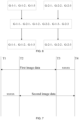
- FIG. 6 is a schematic diagram of a process of processing image data in the present invention.
- the selector uses the pixel-by-pixel acquisition mode, to acquire the image data G-1-1, G-2-1, G-1-2, G-2-2, G-1-3, G-2-3 alternately through the first channel and the second channel.
- the data remapping unit remaps the image data according to the acquisition sequence of the selector, so as to acquire the first image-data series and the second image-data series, where, the first image-data series includes the first image-data pixels G-1-1, G-1-2, and G-1-3 acquired according to the acquisition sequence of the selector; and the second image-data series includes the second image-data pixels G-2-1, G-2-2, and G-2-3 acquired according to the acquisition sequence of the selector.
- the data remapping unit remaps the acquired image data according to the acquisition sequence, which may include, but is not limited to, the following implementation manners.
- the data remapping unit extracts by interval form the image-data pixels in the image data according to the acquisition sequence, arranges the image-data pixels extracted by interval whose sequence numbers are odd numbers according to the acquisition sequence of the selector to acquire the first image-data series, and arranges the image-data pixels extracted by interval whose sequence numbers are even values according to the acquisition sequence of the selector to acquire the second image-data series. It can be understood that the example is only used to explain how to acquire the image data in the order of acquisition, and is not used to limit the solution.
- the type of image data acquired by the selector is not particularly limited.
- the image data acquired through the first channel and the second channel by the selector using the pixel-by-pixel acquisition mode may be an analog signal, or the image data acquired through the first channel and the second channel by the selector using the pixel-by-pixel acquisition mode may be digital signal.
- the position of the converters for performing analog-to-digital conversion in the scanning device varies as the type of image data acquired by the selector varies.
- the scanning device further includes a first converter 207 configured between the selector 205 and the data remapping unit 206;
- the first converter 207 when the first converter 207 is configured between the selector 205 and the data remapping unit 206, the format of the image data acquired by the selector 205 is analog signal, and the format of the image data sent by the selector 205 to the first convertor 207 is analog signal. After the analog-to-digital conversion by the first converter 207 the first converter 207 acquires image data in a digital signal format, and the first converter 207 sends the digital signal formatted image data to the data remapping unit 206.
- the second converter 208 when the second converter 208 is configured between the first sensor 201 and the first channel 203, the format of the image data collected by the first sensor 201 is analog signal. After the second converter 208 performs the analog-to-digital conversion, the selector 205 acquires image data in a digital signal format through the first channel 203, and the selector 205 sends the image data in the digital signal format to the data remapping unit 206.
- the location of the first image data collected by the first sensor and the location of the second image data collected by the second sensor are not particularly limited.
- the locations of the first image data and the second image may include, but is not limited to, the following three types.
- the scanning device provided by the present invention can be used for double-sided scanning.
- the first sensor and the second sensor can be located on the upper and lower sides of the to-be-scanned document.
- the first image data is the front-side image data of the to-be-scanned document
- the second image data is the back-side image data of the to-be-scanned document.
- a third type the first image data and the second image data are the back-side image data of the to-be-scanned document.
- application scenarios for the second type and third type may include, but are not limited to, a combination of two A4 format sensors to implement A3 format scanning; or, in flatbed scanning, two sensors are scanned simultaneously from both ends of the to-be-scanned document; or, in the case of flatbed scanning, two sensors are simultaneously scanned from the middle of the to-be-scanned document to both ends; or: in the case of flatbed scanning, one sensor is at the end and the other sensor is in the middle, in this way scanning simultaneously in the same direction.
- the first sensor and the second sensor may be in a positional relationship that is not exactly facing up and down, so as to avoid the first sensor and the second sensor the interference with each other while collecting image data and in the lighting process.
- the design of staggering the position of the two sensors can allow the timing of the first sensor collecting the first image data of the to-be-scanned document to be different from the timing of the second senor collecting the second image data of the to-be-scanned document.
- the scanning device may further include a data filtering unit 210.
- the data filtering unit may use the following but not limited to two methods to remove useless data.
- a first type a first time point and a second time point are determined; and the first image data in the first image-data series collected by the first sensor after the first time point is deleted, and the second image data in the second image-data series collected by the second sensor before the second time point is deleted.
- the first time point is the time when the to-be-scanned document leaves the first sensor
- the second time point is the time when the to-be-scanned document reaches the second sensor
- one or more pixels of the first image data collected by the first sensor after the first time point is useless data, which can be performed with a removal processing can be performed; and one or more pixels of the second image data collected by the second sensor before the second time point is useless data, which can be performed with the removal processing.
- FIG. 7 is a schematic diagram of a process for removing useless data in the present invention.
- the first sensor and the second sensor simultaneously perform image acquisition, and in the scanning device, the first sensor first scans the front-side data of the to-be-scanned document, so that the first image data collected by the first sensor at the time point T1 is the front-side data of the to-be-scanned document.
- the to-be-scanned document has not reached the second sensor, thus, the second image data collected by the second sensor at the time point T1 is useless data.
- the to-be-scanned document reaches the second sensor, the second image data collected by the second sensor beginning from the time point T2 is the reverse-sided data of the to-be-scanned document.
- the to-be-scanned document leaves the first sensor, and the first image data collected by the first sensor after the time point T3 is useless data.
- the to-be-scanned document leaves the second sensor, the first sensor and the second sensor stop the acquisition of the image data.
- xxxxx represents useless data, and the useless data needs to be removed.
- a second type one or more pixels of the first image data at the end of the first image-data series is deleted according to the first specified value, and one or more pixels of the second image data at the start of the second image-data series is deleted according to the second specified value.
- the first specified value and the second specified value may be preset according to actual needs, and the present invention does not specifically limit this.
- the acquired first image-data series and the second image-data series are stored separately.
- the scanning device may further include at least one memory.
- the first image-data series and the second image-data series may be separately stored by two memories, that is, the first image-data series are stored by a first memory, and the second image-data series are stored by a second memory.
- FIG. 8 is a schematic diagram of storing a first image-data series and a second image-data series in the present invention.
- the first image-data series acquired by the data remapping unit 206 are: R-1-1, G-1-1, and B-1-1; the acquired second image-data series are: R-2-1, G-2-1, and B-2-1.
- the first image-data series may be stored by the first memory on the left side in FIG. 8
- the second image-data series may be stored by the second memory on the right side in FIG. 8 to acquire the separately stored first image-data series and the first two image-data series.
- first image-data series and the second image-data series separately by two memories is only a specific implementation manner and is only used to indicate how to separately store the acquired first image-data series and second image-data series and is not intended to limit the present invention.
- the first image-data series and the second image-data series may be separately stored in different locations through a memory to acquire the separately stored first image-data series and second image-data series.
- the specific implementation of the present invention for separately storing the first image-data series and the second image-data series is not particularly limited.
- the acquired first image-data series and the second image-data series may further perform image processing, such as image edge sharpening processing, background removal processing, etc., and the first image-data series and the second image-data series after processed can be stored, which is not limited by the present invention.
- the scanning device in the existing technology includes two sensors and an image acquiring unit, where the two sensors respectively collect the front-side image data and the back-side image data of the to-be-scanned document, so as to acquire the image data collected by the two sensors through an image acquisition unit using an alternate line-by-line manner. Therefore, the scanning device must acquire the data collected by the other sensor after acquiring one line of data of one sensor. Therefore, when the scanning device is used for double-sided scanning of the to-be-scanned document, the scanning speed is half of the scanning speed of a single-sided scanning, the scanning time is long, and the scanning efficiency is low.
- the selector in the present invention acquires image data alternately from the first channel 203 and the second channel 204 by the pixel-by-pixel acquisition mode.
- the selector 205 may acquire a second image-data pixel output by the second sensor 202 by using a time interval after the first sensor 201 outputs a first image-data pixel, acquire a first image-data pixel output by the first sensor 201 by using the time interval after the first sensor 202 outputs a second image-data pixel.
- the length of the data that the selector 205 can collect in one acquisition cycle is smaller than the data length output by the sensors, so that the selector 205 can uninterruptedly and continuously acquire the image data collected by the first sensor 201 and the image data collected by the second sensor 202 alternately.
- the scanning speed of the double-sided scanning is the same as the scanning speed of the single-sided scanning, which greatly saves the scanning time and improves the scanning efficiency.
- the image-forming device 92 is configured to form an image on the image-forming medium based on the image data processed by the scanning device 91.
- the process of performing double-sided scanning by the scanning device shown in FIG. 9(b) is: after the to-be-scanned document passes through the paper feeding port 901, the paper-pickup roller assembly 909 transports the to-be-scanned document along the predetermined paper path in the A/DF to pass through the first sensor 904 and the second sensor 906.
- the first sensor 904 and the second sensor 906 respectively collect the first image data and the second image data of the to-be-scanned document. After the first sensor 904 collects the first image data and the second sensor 906 collects the second image data, after the completing scanning, the to-be-scanned document is discharged to the paper-discharge tray through the paper-discharge roller assembly 905.
- a sensor control unit 1011 is configured to send control signal such as clock control signal, lighting control signal, etc., to the first sensor 1006 and the second sensor 1007.
- the scanning device is also configured with a register bus 1003 connected to the scanning interface 1010.
- the CPU1002 of the scanning device is connected to the scanning interface 1010 through the register bus 1003.
- the CPU1002 can share data with external memory and the USB interface, etc. though the data bus 1001.
- the CPU1002 can send control instruction to the motor controller 1004 though the register bus 1003.
- the motor controller 1004 can send clock signal to the motor 1005 according to the received control instruction.
- the scanning interface 1010, the data acquisition unit 1020, the register bus 1003, and the CPU 1002 and the data bus 1001 in the dashed-line frame in FIG. 10 can be integrated into one controller, so there is no need to add additional image acquisition unit hardware circuit, reducing the cost.
- the image-forming apparatus acquires images by scanning the document simultaneously by two sensors, and processes the images collected by the two sensors through a selector, thereby saving hardware costs and solving the problems of high hardware costs of the scanning device to realize double-sided scanning device.
- FIG. 11 is a schematic flowchart of a scanning method provided by the present invention. As shown in FIG. 11 , the method includes:
- the method further includes: the data remapping unit remapping the acquired image data according to an acquisition sequence of the selector, to acquire a first image-data series and a second-image-data series, where the first image-data series includes the first image data arranged in the acquisition sequence of the selector, and the second image-data series includes the second image data arranged in the acquisition sequence of the selector.
- the scanning method provided by the present invention acquires images by scanning the document simultaneously by two sensors, and processes the images collected by the two sensors through a selector, thereby saving hardware costs and solving the problems of high hardware costs of the scanning device to realize double-sided scanning device.
- the disclosed system, apparatus, and method may be implemented in other manners.
- the device embodiments described above are merely illustrative.
- the division of the unit is only a logical function division, and the actual implementation may have another division manner.
- multiple units or components may be combined or it can be integrated into another system, or some features can be ignored or not executed.
- the coupling or direct coupling or communication connection shown or discussed herein may be an indirect coupling or communication connection through some interface, device or unit, and may be electrical, mechanical or other forms.
- the units described as separate components may or may not be physically separated, and the components displayed as units may or may not be physical units, that is, may be located in one place, or may be distributed to multiple network units. Some or all of the units may be selected according to actual needs to achieve the purpose of the solution of the embodiment.
- each functional unit in each embodiment of the present invention may be integrated into one processing unit, or each unit may exist physically separately, or two or more units may be integrated into one unit.
- the above integrated unit can be implemented in the form of hardware or in the form of hardware and software functional units.
- the above-described integrated unit implemented in the form of a software functional unit can be stored in a computer readable storage medium.
- the software functional unit described above is stored in a storage medium and includes instructions for causing a computer device (which may be a personal computer, a server, or a network device, etc.) or a processor to perform partial steps of the methods of the various embodiments of the present invention.
- the foregoing storage medium may be various medium can store program codes including: a U disk, a mobile hard disk, a read-only memory (ROM), a random access memory (RAM), a magnetic disk, or an optical disk, etc., which can store program codes.
Landscapes
- Engineering & Computer Science (AREA)
- Multimedia (AREA)
- Signal Processing (AREA)
- Environmental & Geological Engineering (AREA)
- Facsimile Scanning Arrangements (AREA)
- Image Input (AREA)
Description
- The present invention relates to the field of image processing technologies, and in particular, to a scanning device, an image-forming apparatus, and a scanning method.
- Specifically, the present invention relates to a scanning device defined in the generic part of
claim 1 attached, to an image forming device comprising such scanning device, and to a scanning method defined in the generic part of claim 8 attached. - Document
US 2010/0123939 A1 discloses a scanning device and a scanning method of the respective generic type as specified above, and a related image forming apparatus. - Specifically, this document discloses a duplex document scanning apparatus and a related method. The duplex document scanning apparatus includes a first image sensor, a second image sensor, a switch module, a data conversion unit, and a scanning control device. The first image sensor senses the first analog image signal, and the second image sensor senses the second analog image signal. The switch module switches the first image sensor and the second image sensor to select the first analog image signal and the second analog image signal. The data conversion unit converts the first and second analog image signals to generate first and second digital image signals. The switch control module of scanning control device generates a switch signal to control the switch module. The scanning control device has a switch control unit and processes the first digital image signal and a second digital image signal. The switch control unit generates a switch signal for controlling the switch module and the switch module simultaneously outputs the first analog image signal and the second analog image signal to the data conversion unit during a signal period of the switch signal.
- At present, to increase the efficiency of reading a document and to improve quietness, etc., a scanning device having a double-sided scanning function is employed in existing technologies.
-
FIG. 1 is a schematic structural diagram of a scanning device used for double-sided scanning in the existing technology. As shown inFIG. 1 , in order to support double-sided scanning of a to-be-scanned document, a scanning device of the existing technology needs to separately configure a corresponding set of hardware modules for each side of the to-be-scanned document. Each set of hardware modules includes a sensor, a convertor, an image processing unit, a boundary processing unit, a frame memory, a selector, an interface. Therefore, in the existing technology, the hardware cost is relatively high when implementing double-sided scanning. - In view of this, the present invention provides a scanning device, an image-forming apparatus, and a scanning method for solving the problems of high hardware cost of the scanning device for realizing double-sided scanning in the existing technology.
- In one aspect, the present invention provides a scanning device according to
claim 1 attached. - This technical solution has the following beneficial effects:
The scanning device provided by the present invention acquires images by scanning the document simultaneously by two sensors, and processes the images collected by the two sensors through a selector, thereby saving hardware costs and solving the problems of high hardware costs of the scanning device to realize double-sided scanning device in the existing technology. Moreover, the working mode that the selector uses a pixel-by-pixel acquisition mode to acquire the image data alternately from the first channel and the second channel, so that the scanning speed of the scanning device when performing double-sided scanning is approximately equal to that of single-sided scanning, improving scanning efficiency. - In another aspect, the present invention further provides an image-forming apparatus according to claim 7 attached.
- This technical solution has the following beneficial effects:
The image-forming apparatus provided by the present invention acquires images by scanning the document simultaneously by two sensors, and processes the images collected by the two sensors through a selector, thereby saving hardware costs and solving the problems of high hardware costs of the scanning device to realize double-sided scanning device. Moreover, the working mode that the selector uses a pixel-by-pixel acquisition mode to acquire the image data alternately from the first channel and the second channel, so that the scanning speed of the scanning device when performing double-sided scanning is approximately equal to that of single-sided scanning, improving scanning efficiency. - In another aspect, the application further provides a scanning method according to claim 8 attached.
- This technical solution has the following beneficial effects:
The scanning method provided by the present invention, acquires images by scanning the document simultaneously by two sensors, and processes the images collected by the two sensors through a selector, thereby saving hardware costs and solving the problems of high hardware costs of the scanning device to realize double-sided scanning device. Moreover, the working mode that the selector uses a pixel-by-pixel acquisition mode to acquire the image data alternately from the first channel and the second channel, so that the scanning speed of the scanning device when performing double-sided scanning is approximately equal to that of single-sided scanning, improving scanning efficiency. - Preferred embodiments of the invention are defined in dependent claims attached.
- In order to more clearly illustrate the technical solutions of the present invention, the drawings to be used in the embodiments will be briefly described below. It is obvious that the drawings in the following description are only some embodiments of the present invention. A person of ordinary skills in the art, other drawings can be acquired from these drawings without any creative work.
-
FIG. 1 is a schematic structural diagram of a scanning device for double-sided scanning in the existing technology; -
FIG. 2(a) is a first schematic structural diagram of a scanning device provided by the present invention; -
FIG. 2(b) is a second schematic structural diagram of a scanning device provided by the present invention; -
FIG. 3 is a schematic diagram of a signal frequency of a scanning device provided by the present invention; -
FIG. 4 is a schematic diagram of control signals in the present invention; -
FIG. 5 is a schematic diagram of a selector acquiring image data in the present invention; -
FIG. 6 is a schematic diagram of a process of processing image data in the present invention; -
FIG. 7 is a schematic diagram of a process of removing useless data in the present invention; -
FIG. 8 is a schematic diagram of storing a first image-data series and a second image-data series in the present invention; -
FIG. 9(a) is a first schematic structural diagram of an image-forming apparatus provided by the present invention; -
FIG. 9(b) is a second schematic structural diagram of an image-forming apparatus provided by the present invention; -
FIG. 10 is a third schematic structural diagram of a scanning device provided by the present invention; -
FIG. 11 is a schematic flow chart of a scanning method provided by the present invention. - In order to better understand the technical solutions of the present invention, the present invention will be described in detail below with reference to the accompanying drawings.
- It should be understood that the described embodiments are only a part of the embodiments of the present invention, and not all of the embodiments. All other embodiments acquired by a person of ordinary skill in the art based on the embodiments of the present invention without departing from the inventive scope are the scope of the present invention.
- The terms used in the present invention are for the purpose of describing particular embodiments only and are not intended to limit the invention. The singular forms "a", "said" and "the" used in the present invention and the appended claims are also intended to include a plurality of forms unless the context clearly indicates otherwise.
- It should be understood that the term "and/or" as used herein is merely describing relationships of contextual objects, indicating that there may be three relationships, for example, A and/or B, which may indicate that A only, A and B, and B only. In addition, the character "/" in this present invention generally indicates that the contextual object is an "or" relationship.
- It should be understood that although the terms first, second, etc. may be used in this invention to describe sensors, etc., these sensors and the like should not be limited to these terms. These terms are only used to distinguish sensors and the like from each other. For example, the first sensor may also be referred to as a second sensor without departing from the scope of the present invention. Similarly, the second sensor may also be referred to as a first sensor.
- Depending on the context, the word "if" as used herein may be interpreted as "when" or "if" or "in response to determining" or "in response to detecting." Similarly, depending on the context, the phrase "if determined" or "if detected (conditions or events stated)" can be interpreted as "when determined" or "in response to determination" or "when detected (stated condition or event)" or "in response to a test (condition or event stated)".
- The present invention provides a scanning device.
FIG. 2(a) is a first schematic structural diagram of a scanning device provided by the present invention.FIG. 2(b) is a second schematic structural diagram of the scanning device provided by the present invention. - As shown in
FIG. 2(a) or as shown inFIG. 2(b) , the scanning device includes afirst sensor 201, asecond sensor 202, afirst channel 203 corresponding to thefirst sensor 201, and asecond channel 204 corresponding to thesecond sensor 202, andselector 205; - the
first sensor 201 is configured to collect first image data of a to-be-scanned document; - the
second sensor 202 is configured to collect second image data of the to-be-scanned document; and - the
selector 205 is configured to acquire image data alternately from thefirst channel 203 and thesecond channel 204 to acquire a first image data from thefirst channel 203 and a second image data from thesecond channel 204 by using a pixel-by-pixel acquisition mode in one acquisition cycle. - Specifically, in the present invention, the to-be-scanned document may include, but is not limited to, at least one of a document, a credential, an image, or a photo, which is not specifically limited in the present invention.
- It should be noted that, as shown in
FIG. 2(a) orFIG. 2(b) , the scanning device provided by the present invention may include, but is not limited to, two channels including thefirst channel 203 and thesecond channel 204. The two channels may be arbitrarily selected by theselector 205 from at least two channels in the scanning device as thefirst channel 203 and thesecond channel 204, to acquire the first image data through thefirst channel 203 and acquire the second image data through thesecond channel 204. This invention does not specifically limit this. - Specifically, in the present invention, as shown in
FIG. 2(a) or as shown inFIG. 2(b) , theselector 205 uses a pixel-by-pixel acquisition mode, also referred as to an acquisition mode as a pixel by a pixel, to acquire the image data alternately from thefirst channel 203 and thesecond channel 204. The pixel of the first image data is acquired through thefirst channel 203 and the pixel of the second image is acquired through thesecond channel 204 in one acquisition cycle. For example, the pixel of the first image data may be a first image-data pixel and the pixel of the second image data may be a second image-data pixel. - In the present invention, the
selector 205 uses the pixel-by-pixel acquisition mode to acquire image data alternately from the first channel and the second channel, that is, theselector 205 can utilize the time interval of thefirst sensor 201 outputting two first image-data pixels to acquire the pixel of the second image data output by thesecond sensor 202, and similarly, also can utilize the time interval of thesecond sensor 202 outputting two second image-data pixels, to acquire the pixel of the first image data output by thefirst sensor 201, thereby improving the efficiency of the selector to acquire pixel points of image data. - Specifically, in the present invention, as shown in
FIG. 2(a) or as shown inFIG. 2(b) , the selection frequency when theselector 205 selects a channel is greater than or equal to twice the output frequency of thefirst sensor 201; and/or, the selection frequency when theselector 205 selects the channel is greater than or equal to twice the output frequency of thesecond sensor 202. - In a specific implementation process, as shown in
FIG. 2(a) or as shown inFIG. 2(b) , when the output frequency of thefirst sensor 201 is the same as the output frequency of thesecond sensor 202, the selection frequency when theselector 205 selects the channel is greater than or equal to twice the output frequency of thefirst sensor 201. Therefore, in the case where the data lengths processed by thefirst sensor 201, thesecond sensor 202, and theselector 205 are the same, the output frequency of the data output by thefirst sensor 201 and thesecond sensor 202 is f1; and the selection frequency when theselector 205 selects the channel is greater than twice the output frequency when thefirst sensor 201 outputs data, that is, the selection frequency when theselector 205 selects the channel is greater than 2×f1. - Further preferably, as shown in
FIG. 2(a) or as shown inFIG. 2(b) , if the number of bits when thefirst sensor 201 outputs data is n1, the number of bits when theselector 205 acquires data is n2, the selection frequency when theselector 205 in the image acquisition unit selects the channel is greater than or equal to 2×n2/n1 times the output frequency of thefirst sensor 201. That is, even if n1>n2, the selection frequency of theselector 205 is very fast, the data of thefirst sensor 201 and the data of thesecond sensor 202 can be simultaneously acquired, and theselector 205 in one cycle can select the data offirst sensor 201 and thesecond sensor 202 in n2/n1 cycle. In this way, the data length that theselector 205 can collect in one acquisition cycle is smaller than the data length output by the sensor, thereby ensuring that theselector 205 can acquire the image data collected by thefirst sensor 201 and the image data collected by thesecond sensor 202 in an uninterrupted, continuous, and cross-flow manner. - Therefore, in the above technical solution provided by the embodiment, the scanning speed of the double-sided scanning of the to-be-scanned document is the same as the scanning speed of the single-sided scanning, which greatly saves the scanning time and improves the scanning efficiency.
-
FIG. 3 is a schematic diagram of signal frequency of the scanning device provided by the present invention. As shown inFIG. 3 , the VSMP (video sample timing pulse) represents a clock control signal, and thefirst sensor 201 collects the first image data after receiving the clock control signal, and thesecond sensor 202 collects the second image data after receiving the clock control signal. The signal transmitted by thefirst sensor 201 is Sig1, the signal transmitted by thesecond sensor 202 is Sig2, and 1, 2, 3, 4, 5, and 6 in the Sig1 signal line and the Sig2 signal line represent image-data pixels. DATA CLK is a selection signal when theselector 205 selects thefirst channel 203 or selects thesecond channel 204 to acquire image data. InFIG. 3 , two vertical dashed lines indicate different channels, and the data signal is the image-data signal acquired by theselector 205. Specifically, the 1 and 2 in front of the dash line of 1-2, 1-3, 1-4, 1-5, 1-6, 2-1, 2-2, 2-3, 2-4, and 2-5 in the data signal line respectively represent the channel selected when acquiring data. The 1, 2, 3, 4, 5, and 6 behind the dash line respectively represent different image-data pixels in each channel. - As shown in
FIG. 3 , the VSMP signal is loose, i.e., the output frequencies of thefirst sensor 201 and thesecond sensor 202 are low, assuming it is f1. The DATA CLK signal is dense, indicating that in a selection cycle the frequency of theselector 205 selecting thefirst channel 203 or selecting thesecond channel 204 is relatively frequent, that is, the selection frequency of theselector 205 is high, assuming that the selection frequency of theselector 205 is f2. In a specific implementation process, in order to implement the pixel-by-pixel acquisition mode by theselector 205, the image data is acquired alternately from thefirst channel 203 and thesecond channel 204, and the selection frequency f2 of the DATA CLK signal may be twice or more of the signal frequency f1 of the VSMP signal, that is, the selection frequency f2 when theselector 205 selects a channel needs to be greater than or equal to 2f1. - In a specific implementation process, after receiving the control signal sent by the sensor control unit, the first sensor acquires first image data of the color indicated by the control signal, and after receiving the control signal sent by the sensor control unit, accordingly the second sensor acquires the second image data of the color indicated by the control signal.
- It should be noted that, in the present invention, the control signals received by the first sensor and the second sensor may include, but are not limited to, at least one of a clock control signal or a lighting control signal.
- Specifically, the first sensor may acquire the first image data at a specified time point according to the received clock control signal, or acquire the first image data immediately after receiving the clock control signal. And the second sensor may acquire the second image data at a specified time point according to the received clock control signal, or acquire the second image data immediately after receiving the clock control signal.
- Specifically, the first sensor may collect the first image data of the color indicated by the lighting control signal according to the received lighting control signal, and the second sensor may collect the second image data of the color indicated by the lighting control signal according to the received lighting control signal.
- Specifically, the control signals sent by the sensor control unit to the first sensor and the second sensor may be the same and may be different, which is not specifically limited in the present invention.
- Specifically,
FIG. 4 is a schematic diagram of a control signal in the present invention. As shown inFIG. 4 , TR is a clock control signal sent by the sensor control unit to thefirst sensor 201 and thesecond sensor 202, and Sig1 is a signal diagram of the pixel of the first image data acquired by theselector 205 through thefirst channel 203, and Sig2 is a signal diagram of the pixel of the second image data acquired by theselector 205 through thesecond channel 204, where R represents a red image data signal when the red light is turned on, G represents a green image data signal when the green light is turned on, and B represents a blue image data signal when the blue light is turned on. - It should be noted that, after receiving the control signal, the first sensor and the second sensor acquire image data of a color indicated by the control signal, the selector acquiring the image data through the first channel and the second channel is one cycle later after the lighting control signal is sent out.
- Specifically, as shown in
FIG. 4 , when the sensor control unit transmits the clock control signal and the lighting control signal of the red light at the time point Ta, the R signal changes from the low level to the high level when the TR is at the time point Ta, and the red light is turned on. At this time, the first sensor collects the first image data of red color according to the received clock control signal and the lighting control signal of the red light, and the second sensor collects the second image data of red color according to the received clock control signal and the lighting control signal of the red light. The Sig1 signal is represented as R at the time point Tb, that is, the selector acquires the first image data of red color through the first channel at the time point Tb, and the Sig2 signal is represented as R at the time point Tb, that is the selector acquires the second image data of red color through the second channel at the time point Tb. - Similarly, as shown in
FIG. 4 , when the sensor control unit transmits the clock control signal and the lighting control signal of the green light at the time point Tb, the G signal changes from the low level to the high level when the TR is at the time point Tb, and the green light is turned on. At this time, the first sensor collects the first image data of green color according to the received clock control signal and the lighting control signal of the green light, and the second sensor collects the second image data of green color according to the received clock control signal and the lighting control signal of the green light. The Sig1 signal is represented as G at the time point Tc, that is, the selector acquires the first image data of green color through the first channel at the time point Tc, and the Sig2 signal is represented as G at the time point Tc, that is the selector acquires the second image data of green color through the second channel at the time point Tc. - Similarly, as shown in
FIG. 4 , when the sensor control unit transmits the clock control signal and the lighting control signal of the blue light at the time point Tc, the B signal changes from the low level to the high level when the TR is at the time point Tc, and the blue light is turned on. At this time, the first sensor collects the first image data of blue color according to the received clock control signal and the lighting control signal of the blue light, and the second sensor collects the second image data of blue color according to the received clock control signal and the lighting control signal of the blue light. The Sig1 signal is represented as B at the time point Td, that is, the selector acquires the first image data of blue color through the first channel at the time point Td, and the Sig2 signal is represented as B at the time point Td, that is the selector acquires the second image data of blue color through the second channel at the time point Td. - Based on this, the selector uses the pixel-by-pixel acquisition mode, and the image data acquired alternately from the first channel and the second channel is the intersection data of the first image data collected by the first sensor and the second image data collected by the second sensor.
- Taking
FIG. 5 as an example for illustration,FIG. 5 is a schematic diagram of the image data acquired by the selector in the present invention. - Specifically, in the embodiment of the present invention, the image-data pixel point may be represented by the "X-Y-Z" form, where X represents the light is turned on, Y represents the channel, and Z represents the image-data pixel. Specifically, X can be R, G, and B, where R represents the red light, G represents the green light, B represents the blue light. As shown in
FIG. 5 , R-1-1, R-1-2, and R-1-3 are the first image-data pixels collected by the first sensor, where R-1-2 represents when the red light is turned on, the first channel, and the second image-data pixel. B-2-1, B-2-2, and B-2-3 are the second image-data pixels collected by the second sensor, where B-2-3 represents when the blue light is turned on, the second channel, and 3 in the 2-3 represents the third image-data pixel of blue color collected by the second sensor. - As shown in
FIG. 5 , when the red light is on, the selector uses the pixel-by-pixel acquisition mode to acquire image data alternately from the first channel and the second channel, after acquiring the first image-data pixel R-1-1 through the first channel, acquires a second image-data pixel R-2-1 through the second channel, and then acquires the image data alternately through the first channel and the second channel. Further, the selector uses the pixel-by-pixel acquisition mode, to acquire the image data R-1-1, R-2-1, R-1-2, R-2-2, R-1-3, and R-2-3 alternately through the first channel and the second channel. The image data is the intersection data of the first image data collected by the first sensor and the second image data collected by the second sensor. - Similarly, as shown in
FIG. 5 , when the green light is on, the selector uses the pixel-by-pixel acquisition mode to acquire image data alternately from the first channel and the second channel, after acquiring the first image-data pixel G-1-1 through the first channel, acquires a second image-data pixel G-2-1 through the second channel, and then acquires the image data alternately through the first channel and the second channel. Further, the selector uses the pixel-by-pixel acquisition mode, to acquire the image data G-1-1, G-2-1, G-1-2, G-2-2, G-1-3, and G-2-3 alternately through the first channel and the second channel. The image data is the intersection data of the first image data collected by the first sensor and the second image data collected by the second sensor. - Similarly, as shown in
FIG. 5 , when the blue light is on, the selector uses the pixel-by-pixel acquisition mode to acquire image data alternately from the first channel and the second channel, after acquiring the first image-data pixel B-1-1 through the first channel, acquires a second image-data pixel B-2-1 through the second channel, and then acquires the image data alternately through the first channel and the second channel. Further, the selector uses the pixel-by-pixel acquisition mode, to acquire the image data B-1-1, B-2-1, B-1-2, B-2-2, B-1-3, and B-2-3 alternately through the first channel and the second channel. The image data is the intersection data of the first image data collected by the first sensor and the second image data collected by the second sensor. - Specifically, in the present invention, as shown in
FIG. 2(a) or as shown inFIG. 2(b) , the scanning device further includes adata remapping unit 206, and it should be noted that thedata remapping unit 206 can be not only configured as belonging to a portion of the scanning device, but also can be configured as belonging to a portion of a computer connected to the scanning device. - As shown in
FIG. 2(a) orFIG. 2(b) , thedata remapping unit 206 is configured to remap the acquired image data according to an acquisition sequence to acquire a first image-data series and a second image-data series. The first image-data series includes first image data arranged in the sequence of acquisition of theselector 205, and the second image-data series includes second image data arranged in the sequence of acquisition of theselector 205. - Taking
FIG. 6 as an example for illustration,FIG. 6 is a schematic diagram of a process of processing image data in the present invention. - As shown in
FIG. 6 , when the G light is turned on, the first image-data pixels collected by the first sensor are G-1-1, G-1-2, G-1-3, and the second image-data pixels collected by the second sensor are G-2-1, G-2-2, and G-2-3. Then the selector uses the pixel-by-pixel acquisition mode, to acquire the image data G-1-1, G-2-1, G-1-2, G-2-2, G-1-3, G-2-3 alternately through the first channel and the second channel. The data remapping unit remaps the image data according to the acquisition sequence of the selector, so as to acquire the first image-data series and the second image-data series, where, the first image-data series includes the first image-data pixels G-1-1, G-1-2, and G-1-3 acquired according to the acquisition sequence of the selector; and the second image-data series includes the second image-data pixels G-2-1, G-2-2, and G-2-3 acquired according to the acquisition sequence of the selector. - In a specific implementation process, the data remapping unit remaps the acquired image data according to the acquisition sequence, which may include, but is not limited to, the following implementation manners.
- For example, for the acquired image data, the data remapping unit extracts by interval form the image-data pixels in the image data according to the acquisition sequence, arranges the image-data pixels extracted by interval whose sequence numbers are odd numbers according to the acquisition sequence of the selector to acquire the first image-data series, and arranges the image-data pixels extracted by interval whose sequence numbers are even values according to the acquisition sequence of the selector to acquire the second image-data series. It can be understood that the example is only used to explain how to acquire the image data in the order of acquisition, and is not used to limit the solution.
- It should be noted that, in the present invention, the type of image data acquired by the selector is not particularly limited. Specifically, the image data acquired through the first channel and the second channel by the selector using the pixel-by-pixel acquisition mode may be an analog signal, or the image data acquired through the first channel and the second channel by the selector using the pixel-by-pixel acquisition mode may be digital signal.
- It can be understood that the position of the converters for performing analog-to-digital conversion in the scanning device varies as the type of image data acquired by the selector varies.
- Specifically, in a specific implementation process, referring to
FIG. 2(a) , the scanning device further includes afirst converter 207 configured between theselector 205 and thedata remapping unit 206; - the
first converter 207 is configured to perform analog-to-digital conversion on image data acquired by theselector 205; and - the
first converter 207 is further configured to send the image data acquired by the analog-to-digital conversion to thedata remapping unit 206 according to the acquisition sequence of theselector 205. - It can be understood that, as shown in
FIG. 2(a) , when thefirst converter 207 is configured between theselector 205 and thedata remapping unit 206, the format of the image data acquired by theselector 205 is analog signal, and the format of the image data sent by theselector 205 to thefirst convertor 207 is analog signal. After the analog-to-digital conversion by thefirst converter 207 thefirst converter 207 acquires image data in a digital signal format, and thefirst converter 207 sends the digital signal formatted image data to thedata remapping unit 206. - Specifically, in another specific implementation process, referring to
FIG. 2(b) , the scanning device further includes asecond converter 208 configured between thefirst sensor 201 and thefirst channel 203, and athird converter 209 configured between the second sensor the 202 and thesecond channel 204. - As shown in
FIG. 2(b) , thesecond converter 208 is configured to perform the analog-to-digital conversion on the first image data collected by thefirst sensor 201, and thethird converter 209 is configured to perform the analog-to-digital conversion on the second image data collected by thesecond sensor 202. - It can be understood that, as shown in
FIG. 2(b) , when thesecond converter 208 is configured between thefirst sensor 201 and thefirst channel 203, the format of the image data collected by thefirst sensor 201 is analog signal. After thesecond converter 208 performs the analog-to-digital conversion, theselector 205 acquires image data in a digital signal format through thefirst channel 203, and theselector 205 sends the image data in the digital signal format to thedata remapping unit 206. - Similarly, as shown in
FIG. 2(b) , when thethird converter 209 is configured between thesecond sensor 202 and thesecond channel 204, the format of the image data collected by thesecond sensor 202 is analog signal, and after the third heconverter 209 performs the analog-to-digital conversion, theselector 205 acquires image data in a digital signal format through thesecond channel 204, and theselector 205 sends the image data in the digital signal format to thedata remapping unit 206. - It should be noted that, in the present invention, as shown in
FIG. 2 ( a ) or as shown inFIG. 2(b) , only one-time analog-to-digital conversion needs to be performed on the first image data and the second image data, and therefore, thefirst converter 207 between theselector 205 and thedata remapping unit 206 performs the analog-to-digital conversion on the image data acquired by theselector 205, so that there is no need to provide asecond convertor 208 between thefirst sensor 201 and thefirst channel 203, and there is no need to provide athird convertor 209 between thesecond convertor 202 and thesecond channel 204. Or, thesecond converter 208 between thefirst sensor 201 and thefirst channel 203 performs the analog-to-digital conversion on the first image data acquired by thefirst sensor 201, thethird convertor 209 between thesecond sensor 202 and thesecond channel 204 performs the analog-to-digital conversion on the second image data acquired by thesecond sensor 202, so that there is no need to provide thefirst convertor 207 between theselector 205 and thedata remapping unit 206. - It should be noted that, in the present invention, the location of the first image data collected by the first sensor and the location of the second image data collected by the second sensor are not particularly limited. Specifically, the locations of the first image data and the second image may include, but is not limited to, the following three types.
- A first type: the first image data is the front-side image data of the to-be-scanned document, and the second image data is the back-side image data of the to-be-scanned document.
- It can be understood that the scanning device provided by the present invention can be used for double-sided scanning. In this case, the first sensor and the second sensor can be located on the upper and lower sides of the to-be-scanned document. At this time, the first image data is the front-side image data of the to-be-scanned document, and the second image data is the back-side image data of the to-be-scanned document.
- A second type: the first image data and the second image data are frontal image data of the to-be-scanned document.
- A third type: the first image data and the second image data are the back-side image data of the to-be-scanned document.
- It can be understood that the scanning device provided by the present invention can also be used for single-sided scanning. At this time, the first sensor and the second sensor are located on the same side of the to-be-scanned document, and at this time, according to the scanning side that is required according to the to-be-scanned document, the first image data and the second image data are the front-side image data of the to-be-scanned document, or the first image data and the second image data are the back-side image data of the to-be-scanned document.
- Specifically, in the present invention, application scenarios for the second type and third type may include, but are not limited to, a combination of two A4 format sensors to implement A3 format scanning; or, in flatbed scanning, two sensors are scanned simultaneously from both ends of the to-be-scanned document; or, in the case of flatbed scanning, two sensors are simultaneously scanned from the middle of the to-be-scanned document to both ends; or: in the case of flatbed scanning, one sensor is at the end and the other sensor is in the middle, in this way scanning simultaneously in the same direction.
- Specifically, when the scanning device provided by the present invention is used for double-sided scanning, the first sensor and the second sensor may be in a positional relationship that is not exactly facing up and down, so as to avoid the first sensor and the second sensor the interference with each other while collecting image data and in the lighting process. The design of staggering the position of the two sensors can allow the timing of the first sensor collecting the first image data of the to-be-scanned document to be different from the timing of the second senor collecting the second image data of the to-be-scanned document. When the double-sided scanning is performed, assuming the front-side data of the to-be-scanned document is first scanned, after the front-side data is scanned, the useless data in the image data collected by the sensor needs to be deleted, and before the revise-side data is scanned, the useless data in the image data collected by the sensor needs to be deleted.
- Specifically, in the present invention, as shown in
FIG. 2(a) or as shown inFIG. 2(b) , the scanning device may further include adata filtering unit 210. Specifically, when the data filtering unit may use the following but not limited to two methods to remove useless data. - A first type: a first time point and a second time point are determined; and the first image data in the first image-data series collected by the first sensor after the first time point is deleted, and the second image data in the second image-data series collected by the second sensor before the second time point is deleted.
- It should be noted that the first time point is the time when the to-be-scanned document leaves the first sensor, and the second time point is the time when the to-be-scanned document reaches the second sensor.
- It can be understood that one or more pixels of the first image data collected by the first sensor after the first time point is useless data, which can be performed with a removal processing can be performed; and one or more pixels of the second image data collected by the second sensor before the second time point is useless data, which can be performed with the removal processing.
- For example, it is assumed that the first sensor and the second sensor may be in a positional relationship that is not exactly facing up and down, and the first sensor first scans the front-side data of the document to be processed. At this time,
FIG. 7 can be referred to, which is a schematic diagram of a process for removing useless data in the present invention. - As shown in
FIG. 7 , at time point T1, the first sensor and the second sensor simultaneously perform image acquisition, and in the scanning device, the first sensor first scans the front-side data of the to-be-scanned document, so that the first image data collected by the first sensor at the time point T1 is the front-side data of the to-be-scanned document. However, at this time, the to-be-scanned document has not reached the second sensor, thus, the second image data collected by the second sensor at the time point T1 is useless data. Till the time point T2, the to-be-scanned document reaches the second sensor, the second image data collected by the second sensor beginning from the time point T2 is the reverse-sided data of the to-be-scanned document. At the time point T3, the to-be-scanned document leaves the first sensor, and the first image data collected by the first sensor after the time point T3 is useless data. At the time point T4, the to-be-scanned document leaves the second sensor, the first sensor and the second sensor stop the acquisition of the image data. As shown inFIG. 7 , xxxxx represents useless data, and the useless data needs to be removed. - As shown in
FIG. 7 , only the first time point T3 and the second time point T2 need to be determined. Therefore, one or more pixels of the first image data in the first image-data series collected by the first sensor after the time point T3 is deleted. One or more pixels of the second image data in the second image-data series collected by the second sensor before the T2 time point is deleted, so that the useless data collected can be deleted. - A second type: one or more pixels of the first image data at the end of the first image-data series is deleted according to the first specified value, and one or more pixels of the second image data at the start of the second image-data series is deleted according to the second specified value.
- Specifically, in the present invention, the first specified value and the second specified value may be preset according to actual needs, and the present invention does not specifically limit this.
- It can be understood that, in the present invention, after the data acquired by the selector is remapped by the data remapping unit to acquire the first image-data series and the second image-data series, the acquired first image-data series and the second image-data series are stored separately.
- Specifically, in the present invention, the scanning device may further include at least one memory.
- In a specific implementation process, the first image-data series and the second image-data series may be separately stored by two memories, that is, the first image-data series are stored by a first memory, and the second image-data series are stored by a second memory.
- Specifically,
FIG. 8 is a schematic diagram of storing a first image-data series and a second image-data series in the present invention. As shown inFIG. 8 , the first image-data series acquired by thedata remapping unit 206 are: R-1-1, G-1-1, and B-1-1; the acquired second image-data series are: R-2-1, G-2-1, and B-2-1. The first image-data series may be stored by the first memory on the left side inFIG. 8 , and the second image-data series may be stored by the second memory on the right side inFIG. 8 to acquire the separately stored first image-data series and the first two image-data series. - It can be understood that storing the first image-data series and the second image-data series separately by two memories is only a specific implementation manner and is only used to indicate how to separately store the acquired first image-data series and second image-data series and is not intended to limit the present invention. Specifically, in the present invention, the first image-data series and the second image-data series may be separately stored in different locations through a memory to acquire the separately stored first image-data series and second image-data series. The specific implementation of the present invention for separately storing the first image-data series and the second image-data series is not particularly limited.
- It should be noted that, in the present invention, the acquired first image-data series and the second image-data series may further perform image processing, such as image edge sharpening processing, background removal processing, etc., and the first image-data series and the second image-data series after processed can be stored, which is not limited by the present invention.
- It should be noted that, in the existing technology, there is also a scanning device that can be used for double-sided scanning. The scanning device in the existing technology includes two sensors and an image acquiring unit, where the two sensors respectively collect the front-side image data and the back-side image data of the to-be-scanned document, so as to acquire the image data collected by the two sensors through an image acquisition unit using an alternate line-by-line manner. Therefore, the scanning device must acquire the data collected by the other sensor after acquiring one line of data of one sensor. Therefore, when the scanning device is used for double-sided scanning of the to-be-scanned document, the scanning speed is half of the scanning speed of a single-sided scanning, the scanning time is long, and the scanning efficiency is low.
- In contrast, as shown in
FIG. 2(a) or as shown inFIG. 2(b) , the selector in the present invention acquires image data alternately from thefirst channel 203 and thesecond channel 204 by the pixel-by-pixel acquisition mode. In the present invention, theselector 205 may acquire a second image-data pixel output by thesecond sensor 202 by using a time interval after thefirst sensor 201 outputs a first image-data pixel, acquire a first image-data pixel output by thefirst sensor 201 by using the time interval after thefirst sensor 202 outputs a second image-data pixel. Therefore, the length of the data that theselector 205 can collect in one acquisition cycle is smaller than the data length output by the sensors, so that theselector 205 can uninterruptedly and continuously acquire the image data collected by thefirst sensor 201 and the image data collected by thesecond sensor 202 alternately. As such, for the to-be-scanned document, the scanning speed of the double-sided scanning is the same as the scanning speed of the single-sided scanning, which greatly saves the scanning time and improves the scanning efficiency. - One technical solution in the present invention has the following beneficial effects:
the scanning device provided by the present invention acquires images by scanning the document simultaneously by two sensors, and processes the images collected by the two sensors through a selector, thereby saving hardware costs and solving the problems of high hardware costs of the scanning device to realize double-sided scanning device. Moreover, the working mode that the selector uses a pixel-by-pixel acquisition mode to acquire the image data alternately from the first channel and the second channel, so that the scanning speed of the scanning device when performing double-sided scanning is approximately equal to that of single-sided scanning, improving scanning efficiency. - The present invention also provides an image-forming apparatus.
-
FIG. 9(a) is a first structural diagram of an image-forming apparatus provided by the present invention. As shown inFIG. 9(a) , the image-forming apparatus includes thescanning device 91 and the image-formingdevice 92 according toEmbodiment 1. - Specifically, as shown in
FIG. 9(a) , the image-formingdevice 92 is configured to form an image on the image-forming medium based on the image data processed by thescanning device 91. - Specifically, in the present invention, the material of the image-forming medium can be determined according to actual needs, which is not specifically limited in the present invention.
- Specifically, the present invention does not particularly limit the image-forming method of the image-forming
device 92 shown inFIG. 9(a) . For example, the image-formingdevice 92 may employ any one of image-forming methods such as laser image-forming and inkjet image-forming. -
FIG. 9(b) is a second schematic structural diagram of the image-forming apparatus provided by the present invention. - As shown in
FIG. 9(b) , the image-formingapparatus 900 includes the above-described scanning device and image-formingdevice 908, and acontrol device 907 which simultaneously serves as a controller of the scanning device and the image-formingdevice 908. - Specifically, as shown in
FIG. 9(b) , the image-formingdevice 908 is configured to perform image-forming according to image data acquired by the scanning device. - In the present invention, as shown in
FIG. 9(b) , the scanning device includes an automatic document feeder (ADF), and the ADF includes a paper-pickup roller assembly 909 and a paper-discharge roller assembly 905, afirst motor 903 for providing a driving force to the paper-pickup roller assembly 909 and the paper-discharge roller assembly 905, a first sensor 904 for collecting the first image data of the to-be-scanned document, the first sensor located in the ADF frame, and asecond sensor 906, thesecond sensor 906 located below aflatbed scanning platform 910. - In the present invention, as shown in
FIG. 9(b) , the models of the first sensor 904 and thesecond sensor 906 are not particularly limited. Preferably, the first sensor 904 and thesecond sensor 906 may be configured as a contact image sensor (CIS); or the first sensor 904 and thesecond sensor 906 may also be partially or completely configured as a charge coupled device (CCD). - The process of performing double-sided scanning by the scanning device shown in
FIG. 9(b) is: after the to-be-scanned document passes through thepaper feeding port 901, the paper-pickup roller assembly 909 transports the to-be-scanned document along the predetermined paper path in the A/DF to pass through the first sensor 904 and thesecond sensor 906. The first sensor 904 and thesecond sensor 906 respectively collect the first image data and the second image data of the to-be-scanned document. After the first sensor 904 collects the first image data and thesecond sensor 906 collects the second image data, after the completing scanning, the to-be-scanned document is discharged to the paper-discharge tray through the paper-discharge roller assembly 905. - Specifically, as shown in
FIG. 9(b) , the scanning speed when the scanning device performs double-sided scanning, that is, the number of pages that are scanned per minute, can be set based on predetermined parameters, according to the image data collected by the first sensor 904 and thesecond sensor 906, the data transmitting speed, the rotating speed of thefirst motor 903, which is not particularly limited in the present invention. - The process of performing single-sided scanning by the scanning device shown in
FIG. 9(b) is: placing the image to be scanned in the to-be-scanned document facing down on theflatbed scanning platform 910 and moving thesecond sensor 906 through thesecond motor 911. At this time, thesecond sensor 906 can acquire the side of the document with data and complete the single-sided scanning. - Specifically,
FIG. 10 is a third schematic structural diagram of the scanning device provided by the present invention. - As shown in
FIG. 10 , the scanning device provided in this embodiment is provided with a first sensor 1006 (first sensor 904 inFIG. 9(b) ), a second sensor 1007 (second sensor 906 inFIG. 9(b) ), adata acquisition unit 1020, and ascanning interface 1010. Thedata acquisition unit 1020 is also provided with four data channels, a first channel, a second channel, a third channel, and a fourth channel. Thedata acquisition unit 1020 is also configured with aselector 1022 for selecting data from different channels and a convertor 2021. Adata acquisition controller 1013 can perform data processing on the data sent by theselector 1022 and provide control signal when thedata acquisition unit 1020 collects data from different channels. Asensor control unit 1011 is configured to send control signal such as clock control signal, lighting control signal, etc., to thefirst sensor 1006 and thesecond sensor 1007. In addition, the scanning device is also configured with aregister bus 1003 connected to thescanning interface 1010. The CPU1002 of the scanning device is connected to thescanning interface 1010 through theregister bus 1003. The CPU1002 can share data with external memory and the USB interface, etc. though thedata bus 1001. The CPU1002 can send control instruction to themotor controller 1004 though theregister bus 1003. Themotor controller 1004 can send clock signal to themotor 1005 according to the received control instruction. - In a specific implementation process, the
scanning interface 1010, thedata acquisition unit 1020, theregister bus 1003, and theCPU 1002 and thedata bus 1001 in the dashed-line frame inFIG. 10 can be integrated into one controller, so there is no need to add additional image acquisition unit hardware circuit, reducing the cost. - One technical solution in the present invention has the following beneficial effects:
the image-forming apparatus provided by the present invention acquires images by scanning the document simultaneously by two sensors, and processes the images collected by the two sensors through a selector, thereby saving hardware costs and solving the problems of high hardware costs of the scanning device to realize double-sided scanning device. Moreover, the working mode that the selector uses a pixel-by-pixel acquisition mode to acquire the image data alternately from the first channel and the second channel, so that the scanning speed of the scanning device when performing double-sided scanning is approximately equal to that of single-sided scanning, improving scanning efficiency. - Based on the scanning device provided in the first embodiment, the present invention further provides a scanning method.
-
FIG. 11 is a schematic flowchart of a scanning method provided by the present invention. As shown inFIG. 11 , the method includes: - S1101, the first sensor collects first image data of a to-be-scanned document.
- S1102, the second sensor collects second image data of the to-be-scanned document.
It should be noted that, in the present invention, the steps of S1101 and S1102 can be performed simultaneously, and there is no sequence, and the first sensor and the second sensor can simultaneously perform acquisition of image data respectively. - S1103, the selector acquires image data alternately from the first channel and the second channel by using a pixel-by-pixel acquisition mode to acquire a first image data from the first channel and a second image data from the second channel in one acquisition cycle.
- Specifically, the method further includes:
the data remapping unit remapping the acquired image data according to an acquisition sequence of the selector, to acquire a first image-data series and a second-image-data series, where the first image-data series includes the first image data arranged in the acquisition sequence of the selector, and the second image-data series includes the second image data arranged in the acquisition sequence of the selector. - In a specific implementation process, before the data remapping unit remaps the acquired image data according to the acquisition sequence of the selector, the method further includes:
the first converter performing an analog-to-digital conversion on the image data acquired from the first sensor and the second sensor and sending image data acquired after the analog-to-digital conversion to the data remapping unit according to the acquisition sequence of the selector. - In another specific implementation process, the selector uses a pixel-by-pixel acquisition mode to acquire image data alternately from the first channel and the second channel, the method further includes:
- the second converter performing the analog-to-digital conversion on the first image data collected by the first sensor; and
- the third converter performing the analog-to-digital conversion on the second image data collected by the second sensor.
- Specifically, in the present invention, after the data remapping unit remaps the acquired image data according to the acquisition sequence of the selector to acquire the first image-data series and the second image-data series, the method further includes:
- the data filtering unit determining the first time point and the second time point; and the data filtering unit deleting one or more pixels of the first image data in the first image-data series collected by the first sensor after the first time point, and deleting one or more pixels of the second image data in the second image-data series collected by the second sensor before the second time point; or
- the data filtering unit deleting the one or more pixels of the first image data of at an end in the first image-data series according to a first specified value and deleting the one or more pixels of the second image data of at the start of the second image-data series according to a second specified value.
- In a specific implementation process, the selection frequency when the selector selects the channel is greater than or equal to twice the output frequency of the first sensor; and/or, the selection frequency when the selector selects the channel is greater than or equal to twice the output frequency of the second sensor.
- In a specific implementation process, the first image data is front-side image data of a to-be-scanned document, and the second image data is back-side image data of the to-be-scanned document; or the first image data and the second image data are both the front-side image data of the to-be-scanned document; or the first image data and the second image data are both back-side image data of the to-be-scanned document.
- Since the scanning method provided in this embodiment is used for the scanning device shown in
FIG. 2(a) orFIG. 2(b) , the part not described in detail in this embodiment can be referred toFIG. 2(a) orFIG. 2 (b) related instructions. - One technical solution in the present invention has the following beneficial effects:
The scanning method provided by the present invention, acquires images by scanning the document simultaneously by two sensors, and processes the images collected by the two sensors through a selector, thereby saving hardware costs and solving the problems of high hardware costs of the scanning device to realize double-sided scanning device. Moreover, the working mode that the selector uses a pixel-by-pixel acquisition mode to acquire the image data alternately from the first channel and the second channel, so that the scanning speed of the scanning device when performing double-sided scanning is approximately equal to that of single-sided scanning, improving scanning efficiency. - A person skilled in the art can clearly understand that for the convenience and brevity of the description, the specific working process of the system, the device and the unit described above can refer to the corresponding process in the foregoing method embodiment, and details are not described herein again.
- In the several embodiments provided by the present invention, it should be understood that the disclosed system, apparatus, and method may be implemented in other manners. For example, the device embodiments described above are merely illustrative. For example, the division of the unit is only a logical function division, and the actual implementation may have another division manner. For example, multiple units or components may be combined or it can be integrated into another system, or some features can be ignored or not executed. In addition, the coupling or direct coupling or communication connection shown or discussed herein may be an indirect coupling or communication connection through some interface, device or unit, and may be electrical, mechanical or other forms.
- The units described as separate components may or may not be physically separated, and the components displayed as units may or may not be physical units, that is, may be located in one place, or may be distributed to multiple network units. Some or all of the units may be selected according to actual needs to achieve the purpose of the solution of the embodiment.
- In addition, each functional unit in each embodiment of the present invention may be integrated into one processing unit, or each unit may exist physically separately, or two or more units may be integrated into one unit. The above integrated unit can be implemented in the form of hardware or in the form of hardware and software functional units.
- The above-described integrated unit implemented in the form of a software functional unit can be stored in a computer readable storage medium. The software functional unit described above is stored in a storage medium and includes instructions for causing a computer device (which may be a personal computer, a server, or a network device, etc.) or a processor to perform partial steps of the methods of the various embodiments of the present invention. The foregoing storage medium may be various medium can store program codes including: a U disk, a mobile hard disk, a read-only memory (ROM), a random access memory (RAM), a magnetic disk, or an optical disk, etc., which can store program codes.
- The above description is only for the preferred embodiments of the present invention and is not intended to limit the present invention.
Claims (13)
- A scanning device (91), comprising: a first sensor (201), a second sensor (202), a first channel (203) corresponding to the first sensor, a second channel (204) corresponding to the second sensor, and a selector (205);the first sensor, being configured to collect first image data of a to-be-scanned document;the second sensor, being configured to collect second image data of the to-be-scanned document; andthe selector is configured to acquire the image data collected by the first sensor and the image data collected by the second sensor in an uninterrupted, continuous and cross-flow manner;the selector, being configured to acquire image data alternately from the first channel and the second channel to acquire a first image data from the first channel and a second image data from the second channel by using a pixel-by-pixel acquisition mode in one acquisition cycle; and characterized in thata selection frequency of the selector to select the first channel or the second channel is greater than or equal to twice of an output frequency of the first sensor; and/or, the selection frequency of the selector to select the first channel or the second channel is greater than or equal to twice of an output frequency of the second sensor.
- The scanning device according to claim 1, wherein the scanning device further comprises a data remapping unit (206);
the data remapping unit is configured to remap the image data acquired from the first sensor and the second sensor according to an acquisition sequence of the selector to acquire a first image-data series and a second image-data series; the first image-data series includes the first image data arranged according to the acquisition sequence of the selector, and the second image-data series includes the second image data arranged according to the acquisition sequence of the selector. - The scanning device according to claim 2, wherein the scanning device further comprises a first converter (207) configured between the selector and the data remapping unit;the first converter is configured to perform an analog-to-digital conversion on the image data acquired by the selector; andthe first converter is further configured to send the image data acquired by the analog-to-digital conversion to the data remapping unit according to the acquisition sequence of the selector.
- The scanning device according to claim 2, wherein the scanning device further comprises a second converter (208) configured between the first sensor and the first channel, a third converter (209) configured between the second sensor and the second channel;the second converter is configured to perform an analog-to-digital conversion on the first image data collected by the first sensor; andthe third converter is configured to perform an analog-to-digital conversion on the second image data collected by the second sensor.
- The scanning device according to claim 2, wherein the scanning device further comprises a data filtering unit (210), configured to:determine the first time point and the second time point; and delete one or more pixels of the first image data in the first image-data series collected by the first sensor after the first time point, and delete one or more pixels of the second image data in the second image-data series collected by the second sensor before the second time point; ordelete one or more pixels of the first image data at an end of the first image-data series according to a first specified value and delete one or more pixels of the second image data at a start of the second image-data series according to a second specified value.
- The scanning device according to any one of claims 1 to 5, whereinthe first image data is front-side image data of the to-be-scanned document, and the second image data is back-side image data of the to-be-scanned document; orthe first image data and the second image data are the front-side image data of the to-be-scanned document; orthe first image data and the second image data are the back-side image data of the to-be-scanned document.
- An image-forming apparatus, wherein the apparatus comprises the scanning device according to any one of claims 1 to 6 and an image-forming device (92); and the image-forming device is configured to form an image on an image-forming medium according to the image data processed by the scanning device.
- A scanning method, the method comprising:collecting, by a first sensor (201), first image data of a to-be-scanned document;collecting, by a second sensor (202), second image data of the to-be-scanned document;using, by a selector (205), a pixel-by-pixel acquisition mode to acquire image data alternately from a first channel (203) and a second channel (204), to acquire a first image data from the first channel and a second image data from the second channel in one acquisition cycle, wherein the selector acquires the image data collected by the first sensor and the image data collected by the second sensor in an uninterrupted, continuous and cross-flow manner, characterized in thata selection frequency of the selector to select the first channel or the second channel is greater than or equal to twice an output frequency of the first sensor; and/or, the selection frequency when the selector selects the first channel or the second channel is greater than or equal to twice an output frequency of the second sensor.
- The method according to claim 8, wherein the method further comprises:
remapping, by a data remapping unit (206), the acquired image data according to an acquisition sequence of the selector, to acquire a first image-data series and a second-image-data series, wherein the first image-data series includes the first image data arranged in the acquisition sequence of the selector, and the second image-data series includes the second image data arranged in the acquisition sequence of the selector. - The method according to claim 9, wherein before the data remapping unit remaps the acquired image data according to the acquisition sequence of the selector, the method further comprises:
performing, by a first converter (207), an analog-to-digital conversion on the image data acquired from the first sensor and the second sensor, and sending image data acquired by the analog-to-digital conversion to the data remapping unit according to the acquisition sequence of the selector. - The method according to claim 9, wherein before the image data is acquired alternately from the first channel and the second channel by using the pixel-by-pixel acquisition mode, the method further comprises:performing, by a second converter (208), an analog-to-digital conversion on the first image data collected by the first sensor; andperforming, by a third converter (209), the analog-to-digital conversion on the second image data collected by the second sensor.
- The method according to claim 9, wherein after the data remapping unit remaps the acquired image data according to the acquisition sequence of the selector to acquire the first image-data series and the second image-data series, the method further includes:determining, by a data filtering unit (210), a first time point and a second time point; and deleting, by the data filtering unit, one or more pixels of the first image data in the first image-data series collected by the first sensor after the first time point, and deleting one or more pixels of the second image data in the second image-data series collected by the second sensor before the second time point; ordeleting, by the data filtering unit, one or more pixels of the first image data at an end in the first image-data series according to a first specified value, and deleting, by the data filtering unit, one or more pixels of the second image data at a start of the first image-data series according to the second specified value.
- A method according to any one of claims 8 to 12, whereinthe first image data is front-side image data of the to-be-scanned document, and the second image data is back-side image data of the to-be-scanned document; orthe first image data and the second image data are the front-side image data of the to-be-scanned document; orthe first image data and the second image data are the back-side image data of the to-be-scanned document.
Applications Claiming Priority (2)
| Application Number | Priority Date | Filing Date | Title |
|---|---|---|---|
| CN201610736117.5A CN106357949B (en) | 2016-08-26 | 2016-08-26 | Scanning device, image forming device and scanning method |
| PCT/CN2017/093524 WO2018036308A1 (en) | 2016-08-26 | 2017-07-19 | Scanning device, imaging apparatus, and scanning method |
Publications (4)
| Publication Number | Publication Date |
|---|---|
| EP3490236A1 EP3490236A1 (en) | 2019-05-29 |
| EP3490236A4 EP3490236A4 (en) | 2019-07-03 |
| EP3490236B1 true EP3490236B1 (en) | 2025-03-26 |
| EP3490236C0 EP3490236C0 (en) | 2025-03-26 |
Family
ID=57855095
Family Applications (1)
| Application Number | Title | Priority Date | Filing Date |
|---|---|---|---|
| EP17842731.6A Active EP3490236B1 (en) | 2016-08-26 | 2017-07-19 | Scanning device, imaging apparatus, and scanning method |
Country Status (5)
| Country | Link |
|---|---|
| US (1) | US10477060B2 (en) |
| EP (1) | EP3490236B1 (en) |
| CN (1) | CN106357949B (en) |
| RU (1) | RU2735942C2 (en) |
| WO (1) | WO2018036308A1 (en) |
Families Citing this family (5)
| Publication number | Priority date | Publication date | Assignee | Title |
|---|---|---|---|---|
| CN106357949B (en) | 2016-08-26 | 2019-08-06 | 珠海赛纳打印科技股份有限公司 | Scanning device, image forming device and scanning method |
| CN110233948B (en) * | 2019-07-15 | 2024-10-29 | 珠海奔图电子有限公司 | Scanning device, image forming apparatus, scanning method, and storage medium |
| CN112100424B (en) * | 2020-08-28 | 2024-06-18 | 中保车服科技服务股份有限公司 | Certificate image classification acquisition method, device, equipment and medium |
| JP7513954B2 (en) * | 2020-10-16 | 2024-07-10 | セイコーエプソン株式会社 | Image reader |
| CN120499521B (en) * | 2025-07-15 | 2025-09-23 | 杭州海康微影传感科技有限公司 | Image data transmission method, device and equipment |
Family Cites Families (26)
| Publication number | Priority date | Publication date | Assignee | Title |
|---|---|---|---|---|
| US4908719A (en) * | 1987-12-26 | 1990-03-13 | Kabushiki Kaisha Toshiba | Scanning apparatus with a mechanism to scan both sides of an original |
| JP2821161B2 (en) * | 1989-03-07 | 1998-11-05 | キヤノン株式会社 | Image information processing device |
| US5280545A (en) * | 1988-12-29 | 1994-01-18 | Canon Kabushiki Kaisha | Image information processing apparatus capable of synthesizing front- and back-surface information |
| US5023711A (en) * | 1989-10-16 | 1991-06-11 | Eastman Kodak Company | Line scanning apparatus using staggered linear segments with adjoining overlap regions |
| JP3428764B2 (en) * | 1995-03-03 | 2003-07-22 | キヤノン株式会社 | Signal processing device |
| US5760919A (en) * | 1995-12-01 | 1998-06-02 | Xerox Corporation | Duplex documents scanner with alternating scan lines from dual imaging stations |
| DE19605938B4 (en) * | 1996-02-17 | 2004-09-16 | Fachhochschule Wiesbaden | scanner |
| JP3353220B2 (en) * | 1996-03-25 | 2002-12-03 | ミノルタ株式会社 | Image processing device |
| US6075622A (en) * | 1997-10-14 | 2000-06-13 | Eastman Kodak Company | Duplex document scanner for processing multiplexed images with a single data path |
| US6160578A (en) * | 1998-06-18 | 2000-12-12 | Redlake Imaging Corporation | High speed, increased bandwidth camera |
| US6512546B1 (en) * | 1998-07-17 | 2003-01-28 | Analog Devices, Inc. | Image sensor using multiple array readout lines |
| CN1395217A (en) * | 2001-07-06 | 2003-02-05 | 力捷电脑股份有限公司 | One-step double-exposure scanning method |
| CN1614985A (en) * | 2003-11-07 | 2005-05-11 | 虹光精密工业(苏州)有限公司 | Image picker and method |
| US7394632B2 (en) * | 2004-09-30 | 2008-07-01 | Rockwell Automation Technologies, Inc. | Line interface module |
| US8929688B2 (en) * | 2004-10-01 | 2015-01-06 | University Of Washington | Remapping methods to reduce distortions in images |
| CN100397860C (en) * | 2004-12-13 | 2008-06-25 | 崴强科技股份有限公司 | Image signal synthesis module and method |
| CN100496081C (en) * | 2005-02-03 | 2009-06-03 | 虹光精密工业(苏州)有限公司 | Duplex Scanner |
| JP4636246B2 (en) * | 2005-06-30 | 2011-02-23 | ブラザー工業株式会社 | Image reading device |
| JP4692115B2 (en) * | 2005-07-11 | 2011-06-01 | ソニー株式会社 | Image processing apparatus and imaging apparatus |
| JP5084677B2 (en) * | 2008-09-12 | 2012-11-28 | キヤノン株式会社 | Document size detector |
| TWI389548B (en) * | 2008-11-14 | 2013-03-11 | Genesys Logic Inc | Duplex document scanning apparatus and method thereof |
| JP5532992B2 (en) * | 2010-02-10 | 2014-06-25 | セイコーエプソン株式会社 | Document camera, document camera control method and program |
| US9143696B2 (en) * | 2012-10-13 | 2015-09-22 | Hewlett-Packard Development Company, L.P. | Imaging using offsetting accumulations |
| JP6324176B2 (en) * | 2014-04-07 | 2018-05-16 | キヤノン株式会社 | Image reading apparatus, control method, program, and system |
| CN104104825B (en) * | 2014-07-03 | 2017-03-29 | 宁波术有电子科技有限公司 | Bearing calibration based on the Double face scanner acquisition system of FPGA |
| CN106357949B (en) * | 2016-08-26 | 2019-08-06 | 珠海赛纳打印科技股份有限公司 | Scanning device, image forming device and scanning method |
-
2016
- 2016-08-26 CN CN201610736117.5A patent/CN106357949B/en active Active
-
2017
- 2017-07-19 RU RU2019103342A patent/RU2735942C2/en active
- 2017-07-19 EP EP17842731.6A patent/EP3490236B1/en active Active
- 2017-07-19 WO PCT/CN2017/093524 patent/WO2018036308A1/en not_active Ceased
-
2019
- 2019-02-15 US US16/276,989 patent/US10477060B2/en active Active
Also Published As
| Publication number | Publication date |
|---|---|
| WO2018036308A1 (en) | 2018-03-01 |
| CN106357949B (en) | 2019-08-06 |
| US20190182403A1 (en) | 2019-06-13 |
| EP3490236A4 (en) | 2019-07-03 |
| RU2019103342A (en) | 2020-09-28 |
| EP3490236C0 (en) | 2025-03-26 |
| RU2735942C2 (en) | 2020-11-11 |
| CN106357949A (en) | 2017-01-25 |
| US10477060B2 (en) | 2019-11-12 |
| EP3490236A1 (en) | 2019-05-29 |
| RU2019103342A3 (en) | 2020-09-28 |
Similar Documents
| Publication | Publication Date | Title |
|---|---|---|
| US10477060B2 (en) | Scanning device, image-forming apparatus, and scanning method | |
| JP6103918B2 (en) | Image processing apparatus and image processing method | |
| CN101355619B (en) | Image forming apparatus and method of controlling the same | |
| US6236759B1 (en) | Image processing apparatus | |
| CN110719375A (en) | Multi-function device, control method thereof, and storage medium | |
| US7710613B2 (en) | Image information apparatus | |
| US20170237873A1 (en) | Image scanning apparatus, control method therefor, and multifunction apparatus | |
| JP6988456B2 (en) | Image processing equipment and programs | |
| JP2011077875A (en) | Image reading apparatus and program | |
| CN112600988B (en) | Image forming device and scanning method | |
| US7995250B2 (en) | Image-reading device employing contact image sensor | |
| US20050052712A1 (en) | Image capturing apparatus and method | |
| US8792144B2 (en) | Image reading device and image reading method | |
| JP4011957B2 (en) | Image copying machine | |
| JP2009060463A (en) | Image reading device | |
| JPH09205524A (en) | Facsimile machine | |
| JP3596839B2 (en) | Digital copier with facsimile function | |
| JP3224385B2 (en) | Image processing device | |
| JP4977672B2 (en) | Halftone dot detection circuit and image processing apparatus having the same | |
| JP2016116171A (en) | Image processing apparatus, control method, and program | |
| EP3220621A1 (en) | Information processing apparatus | |
| JP2023098404A (en) | Image reading device, its control method, and program | |
| JP2008118426A (en) | Image processing apparatus and program | |
| JP2008227822A (en) | Image reading device | |
| JP2003320716A (en) | Printer |
Legal Events
| Date | Code | Title | Description |
|---|---|---|---|
| STAA | Information on the status of an ep patent application or granted ep patent |
Free format text: STATUS: THE INTERNATIONAL PUBLICATION HAS BEEN MADE |
|
| PUAI | Public reference made under article 153(3) epc to a published international application that has entered the european phase |
Free format text: ORIGINAL CODE: 0009012 |
|
| STAA | Information on the status of an ep patent application or granted ep patent |
Free format text: STATUS: REQUEST FOR EXAMINATION WAS MADE |
|
| 17P | Request for examination filed |
Effective date: 20190219 |
|
| AK | Designated contracting states |
Kind code of ref document: A1 Designated state(s): AL AT BE BG CH CY CZ DE DK EE ES FI FR GB GR HR HU IE IS IT LI LT LU LV MC MK MT NL NO PL PT RO RS SE SI SK SM TR |
|
| AX | Request for extension of the european patent |
Extension state: BA ME |
|
| A4 | Supplementary search report drawn up and despatched |
Effective date: 20190531 |
|
| RIC1 | Information provided on ipc code assigned before grant |
Ipc: H04N 1/203 20060101ALI20190524BHEP Ipc: H04N 1/00 20060101AFI20190524BHEP Ipc: H04N 1/024 20060101ALI20190524BHEP Ipc: H04N 1/04 20060101ALI20190524BHEP |
|
| DAV | Request for validation of the european patent (deleted) | ||
| DAX | Request for extension of the european patent (deleted) | ||
| STAA | Information on the status of an ep patent application or granted ep patent |
Free format text: STATUS: EXAMINATION IS IN PROGRESS |
|
| 17Q | First examination report despatched |
Effective date: 20210604 |
|
| GRAP | Despatch of communication of intention to grant a patent |
Free format text: ORIGINAL CODE: EPIDOSNIGR1 |
|
| STAA | Information on the status of an ep patent application or granted ep patent |
Free format text: STATUS: GRANT OF PATENT IS INTENDED |
|
| INTG | Intention to grant announced |
Effective date: 20241107 |
|
| GRAS | Grant fee paid |
Free format text: ORIGINAL CODE: EPIDOSNIGR3 |
|
| GRAA | (expected) grant |
Free format text: ORIGINAL CODE: 0009210 |
|
| STAA | Information on the status of an ep patent application or granted ep patent |
Free format text: STATUS: THE PATENT HAS BEEN GRANTED |
|
| AK | Designated contracting states |
Kind code of ref document: B1 Designated state(s): AL AT BE BG CH CY CZ DE DK EE ES FI FR GB GR HR HU IE IS IT LI LT LU LV MC MK MT NL NO PL PT RO RS SE SI SK SM TR |
|
| REG | Reference to a national code |
Ref country code: GB Ref legal event code: FG4D |
|
| REG | Reference to a national code |
Ref country code: CH Ref legal event code: EP |
|
| REG | Reference to a national code |
Ref country code: DE Ref legal event code: R096 Ref document number: 602017088573 Country of ref document: DE |
|
| REG | Reference to a national code |
Ref country code: IE Ref legal event code: FG4D |
|
| U01 | Request for unitary effect filed |
Effective date: 20250421 |
|
| U07 | Unitary effect registered |
Designated state(s): AT BE BG DE DK EE FI FR IT LT LU LV MT NL PT RO SE SI Effective date: 20250428 |
|
| PG25 | Lapsed in a contracting state [announced via postgrant information from national office to epo] |
Ref country code: RS Free format text: LAPSE BECAUSE OF FAILURE TO SUBMIT A TRANSLATION OF THE DESCRIPTION OR TO PAY THE FEE WITHIN THE PRESCRIBED TIME-LIMIT Effective date: 20250626 |
|
| PG25 | Lapsed in a contracting state [announced via postgrant information from national office to epo] |
Ref country code: NO Free format text: LAPSE BECAUSE OF FAILURE TO SUBMIT A TRANSLATION OF THE DESCRIPTION OR TO PAY THE FEE WITHIN THE PRESCRIBED TIME-LIMIT Effective date: 20250626 |
|
| PG25 | Lapsed in a contracting state [announced via postgrant information from national office to epo] |
Ref country code: HR Free format text: LAPSE BECAUSE OF FAILURE TO SUBMIT A TRANSLATION OF THE DESCRIPTION OR TO PAY THE FEE WITHIN THE PRESCRIBED TIME-LIMIT Effective date: 20250326 |
|
| PG25 | Lapsed in a contracting state [announced via postgrant information from national office to epo] |
Ref country code: GR Free format text: LAPSE BECAUSE OF FAILURE TO SUBMIT A TRANSLATION OF THE DESCRIPTION OR TO PAY THE FEE WITHIN THE PRESCRIBED TIME-LIMIT Effective date: 20250627 |
|
| U20 | Renewal fee for the european patent with unitary effect paid |
Year of fee payment: 9 Effective date: 20250728 |
|
| PG25 | Lapsed in a contracting state [announced via postgrant information from national office to epo] |
Ref country code: SM Free format text: LAPSE BECAUSE OF FAILURE TO SUBMIT A TRANSLATION OF THE DESCRIPTION OR TO PAY THE FEE WITHIN THE PRESCRIBED TIME-LIMIT Effective date: 20250326 |
|
| PG25 | Lapsed in a contracting state [announced via postgrant information from national office to epo] |
Ref country code: ES Free format text: LAPSE BECAUSE OF FAILURE TO SUBMIT A TRANSLATION OF THE DESCRIPTION OR TO PAY THE FEE WITHIN THE PRESCRIBED TIME-LIMIT Effective date: 20250326 |
|
| PG25 | Lapsed in a contracting state [announced via postgrant information from national office to epo] |
Ref country code: PL Free format text: LAPSE BECAUSE OF FAILURE TO SUBMIT A TRANSLATION OF THE DESCRIPTION OR TO PAY THE FEE WITHIN THE PRESCRIBED TIME-LIMIT Effective date: 20250326 |
|
| PG25 | Lapsed in a contracting state [announced via postgrant information from national office to epo] |
Ref country code: SK Free format text: LAPSE BECAUSE OF FAILURE TO SUBMIT A TRANSLATION OF THE DESCRIPTION OR TO PAY THE FEE WITHIN THE PRESCRIBED TIME-LIMIT Effective date: 20250326 |
|
| PG25 | Lapsed in a contracting state [announced via postgrant information from national office to epo] |
Ref country code: IS Free format text: LAPSE BECAUSE OF FAILURE TO SUBMIT A TRANSLATION OF THE DESCRIPTION OR TO PAY THE FEE WITHIN THE PRESCRIBED TIME-LIMIT Effective date: 20250726 |
|
| PG25 | Lapsed in a contracting state [announced via postgrant information from national office to epo] |
Ref country code: CZ Free format text: LAPSE BECAUSE OF FAILURE TO SUBMIT A TRANSLATION OF THE DESCRIPTION OR TO PAY THE FEE WITHIN THE PRESCRIBED TIME-LIMIT Effective date: 20250326 |
|
| PLBE | No opposition filed within time limit |
Free format text: ORIGINAL CODE: 0009261 |
|
| STAA | Information on the status of an ep patent application or granted ep patent |
Free format text: STATUS: NO OPPOSITION FILED WITHIN TIME LIMIT |
|
| REG | Reference to a national code |
Ref country code: CH Ref legal event code: L10 Free format text: ST27 STATUS EVENT CODE: U-0-0-L10-L00 (AS PROVIDED BY THE NATIONAL OFFICE) Effective date: 20260211 |
|
| REG | Reference to a national code |
Ref country code: CH Ref legal event code: H13 Free format text: ST27 STATUS EVENT CODE: U-0-0-H10-H13 (AS PROVIDED BY THE NATIONAL OFFICE) Effective date: 20260224 |
|
| 26N | No opposition filed |
Effective date: 20260105 |
|
| GBPC | Gb: european patent ceased through non-payment of renewal fee |
Effective date: 20250719 |
|
| PG25 | Lapsed in a contracting state [announced via postgrant information from national office to epo] |
Ref country code: GB Free format text: LAPSE BECAUSE OF NON-PAYMENT OF DUE FEES Effective date: 20250719 |
|
| PG25 | Lapsed in a contracting state [announced via postgrant information from national office to epo] |
Ref country code: CH Free format text: LAPSE BECAUSE OF NON-PAYMENT OF DUE FEES Effective date: 20250731 |