EP3490016A1 - Thermoelectric conversion module, sensor module, and information processing system - Google Patents
Thermoelectric conversion module, sensor module, and information processing system Download PDFInfo
- Publication number
- EP3490016A1 EP3490016A1 EP16909548.6A EP16909548A EP3490016A1 EP 3490016 A1 EP3490016 A1 EP 3490016A1 EP 16909548 A EP16909548 A EP 16909548A EP 3490016 A1 EP3490016 A1 EP 3490016A1
- Authority
- EP
- European Patent Office
- Prior art keywords
- thermoelectric conversion
- storage material
- heat storage
- heat
- transfer member
- Prior art date
- Legal status (The legal status is an assumption and is not a legal conclusion. Google has not performed a legal analysis and makes no representation as to the accuracy of the status listed.)
- Granted
Links
Images






Classifications
-
- F—MECHANICAL ENGINEERING; LIGHTING; HEATING; WEAPONS; BLASTING
- F28—HEAT EXCHANGE IN GENERAL
- F28D—HEAT-EXCHANGE APPARATUS, NOT PROVIDED FOR IN ANOTHER SUBCLASS, IN WHICH THE HEAT-EXCHANGE MEDIA DO NOT COME INTO DIRECT CONTACT
- F28D20/00—Heat storage plants or apparatus in general; Regenerative heat-exchange apparatus not covered by groups F28D17/00 or F28D19/00
- F28D20/02—Heat storage plants or apparatus in general; Regenerative heat-exchange apparatus not covered by groups F28D17/00 or F28D19/00 using latent heat
-
- B—PERFORMING OPERATIONS; TRANSPORTING
- B65—CONVEYING; PACKING; STORING; HANDLING THIN OR FILAMENTARY MATERIAL
- B65F—GATHERING OR REMOVAL OF DOMESTIC OR LIKE REFUSE
- B65F3/00—Vehicles particularly adapted for collecting refuse
-
- F—MECHANICAL ENGINEERING; LIGHTING; HEATING; WEAPONS; BLASTING
- F28—HEAT EXCHANGE IN GENERAL
- F28D—HEAT-EXCHANGE APPARATUS, NOT PROVIDED FOR IN ANOTHER SUBCLASS, IN WHICH THE HEAT-EXCHANGE MEDIA DO NOT COME INTO DIRECT CONTACT
- F28D20/00—Heat storage plants or apparatus in general; Regenerative heat-exchange apparatus not covered by groups F28D17/00 or F28D19/00
- F28D20/02—Heat storage plants or apparatus in general; Regenerative heat-exchange apparatus not covered by groups F28D17/00 or F28D19/00 using latent heat
- F28D20/021—Heat storage plants or apparatus in general; Regenerative heat-exchange apparatus not covered by groups F28D17/00 or F28D19/00 using latent heat the latent heat storage material and the heat-exchanging means being enclosed in one container
-
- F—MECHANICAL ENGINEERING; LIGHTING; HEATING; WEAPONS; BLASTING
- F28—HEAT EXCHANGE IN GENERAL
- F28F—DETAILS OF HEAT-EXCHANGE AND HEAT-TRANSFER APPARATUS, OF GENERAL APPLICATION
- F28F21/00—Constructions of heat-exchange apparatus characterised by the selection of particular materials
- F28F21/08—Constructions of heat-exchange apparatus characterised by the selection of particular materials of metal
- F28F21/081—Heat exchange elements made from metals or metal alloys
-
- F—MECHANICAL ENGINEERING; LIGHTING; HEATING; WEAPONS; BLASTING
- F28—HEAT EXCHANGE IN GENERAL
- F28F—DETAILS OF HEAT-EXCHANGE AND HEAT-TRANSFER APPARATUS, OF GENERAL APPLICATION
- F28F3/00—Plate-like or laminated elements; Assemblies of plate-like or laminated elements
- F28F3/02—Elements or assemblies thereof with means for increasing heat-transfer area, e.g. with fins, with recesses, with corrugations
-
- G—PHYSICS
- G08—SIGNALLING
- G08G—TRAFFIC CONTROL SYSTEMS
- G08G1/00—Traffic control systems for road vehicles
- G08G1/01—Detecting movement of traffic to be counted or controlled
-
- G—PHYSICS
- G08—SIGNALLING
- G08G—TRAFFIC CONTROL SYSTEMS
- G08G1/00—Traffic control systems for road vehicles
- G08G1/01—Detecting movement of traffic to be counted or controlled
- G08G1/0104—Measuring and analyzing of parameters relative to traffic conditions
- G08G1/0108—Measuring and analyzing of parameters relative to traffic conditions based on the source of data
- G08G1/0116—Measuring and analyzing of parameters relative to traffic conditions based on the source of data from roadside infrastructure, e.g. beacons
-
- G—PHYSICS
- G08—SIGNALLING
- G08G—TRAFFIC CONTROL SYSTEMS
- G08G1/00—Traffic control systems for road vehicles
- G08G1/01—Detecting movement of traffic to be counted or controlled
- G08G1/0104—Measuring and analyzing of parameters relative to traffic conditions
- G08G1/0125—Traffic data processing
- G08G1/0133—Traffic data processing for classifying traffic situation
-
- H—ELECTRICITY
- H02—GENERATION; CONVERSION OR DISTRIBUTION OF ELECTRIC POWER
- H02N—ELECTRIC MACHINES NOT OTHERWISE PROVIDED FOR
- H02N11/00—Generators or motors not provided for elsewhere; Alleged perpetua mobilia obtained by electric or magnetic means
-
- H—ELECTRICITY
- H04—ELECTRIC COMMUNICATION TECHNIQUE
- H04Q—SELECTING
- H04Q9/00—Arrangements in telecontrol or telemetry systems for selectively calling a substation from a main station, in which substation desired apparatus is selected for applying a control signal thereto or for obtaining measured values therefrom
-
- H—ELECTRICITY
- H10—SEMICONDUCTOR DEVICES; ELECTRIC SOLID-STATE DEVICES NOT OTHERWISE PROVIDED FOR
- H10F—INORGANIC SEMICONDUCTOR DEVICES SENSITIVE TO INFRARED RADIATION, LIGHT, ELECTROMAGNETIC RADIATION OF SHORTER WAVELENGTH OR CORPUSCULAR RADIATION
- H10F77/00—Constructional details of devices covered by this subclass
- H10F77/40—Optical elements or arrangements
- H10F77/42—Optical elements or arrangements directly associated or integrated with photovoltaic cells, e.g. light-reflecting means or light-concentrating means
- H10F77/488—Reflecting light-concentrating means, e.g. parabolic mirrors or concentrators using total internal reflection
-
- H—ELECTRICITY
- H10—SEMICONDUCTOR DEVICES; ELECTRIC SOLID-STATE DEVICES NOT OTHERWISE PROVIDED FOR
- H10N—ELECTRIC SOLID-STATE DEVICES NOT OTHERWISE PROVIDED FOR
- H10N10/00—Thermoelectric devices comprising a junction of dissimilar materials, i.e. devices exhibiting Seebeck or Peltier effects
- H10N10/10—Thermoelectric devices comprising a junction of dissimilar materials, i.e. devices exhibiting Seebeck or Peltier effects operating with only the Peltier or Seebeck effects
- H10N10/13—Thermoelectric devices comprising a junction of dissimilar materials, i.e. devices exhibiting Seebeck or Peltier effects operating with only the Peltier or Seebeck effects characterised by the heat-exchanging means at the junction
-
- H—ELECTRICITY
- H10—SEMICONDUCTOR DEVICES; ELECTRIC SOLID-STATE DEVICES NOT OTHERWISE PROVIDED FOR
- H10N—ELECTRIC SOLID-STATE DEVICES NOT OTHERWISE PROVIDED FOR
- H10N10/00—Thermoelectric devices comprising a junction of dissimilar materials, i.e. devices exhibiting Seebeck or Peltier effects
- H10N10/10—Thermoelectric devices comprising a junction of dissimilar materials, i.e. devices exhibiting Seebeck or Peltier effects operating with only the Peltier or Seebeck effects
- H10N10/17—Thermoelectric devices comprising a junction of dissimilar materials, i.e. devices exhibiting Seebeck or Peltier effects operating with only the Peltier or Seebeck effects characterised by the structure or configuration of the cell or thermocouple forming the device
-
- F—MECHANICAL ENGINEERING; LIGHTING; HEATING; WEAPONS; BLASTING
- F28—HEAT EXCHANGE IN GENERAL
- F28D—HEAT-EXCHANGE APPARATUS, NOT PROVIDED FOR IN ANOTHER SUBCLASS, IN WHICH THE HEAT-EXCHANGE MEDIA DO NOT COME INTO DIRECT CONTACT
- F28D20/00—Heat storage plants or apparatus in general; Regenerative heat-exchange apparatus not covered by groups F28D17/00 or F28D19/00
- F28D20/02—Heat storage plants or apparatus in general; Regenerative heat-exchange apparatus not covered by groups F28D17/00 or F28D19/00 using latent heat
- F28D20/026—Heat storage plants or apparatus in general; Regenerative heat-exchange apparatus not covered by groups F28D17/00 or F28D19/00 using latent heat with different heat storage materials not coming into direct contact
-
- F—MECHANICAL ENGINEERING; LIGHTING; HEATING; WEAPONS; BLASTING
- F28—HEAT EXCHANGE IN GENERAL
- F28F—DETAILS OF HEAT-EXCHANGE AND HEAT-TRANSFER APPARATUS, OF GENERAL APPLICATION
- F28F2215/00—Fins
-
- G—PHYSICS
- G01—MEASURING; TESTING
- G01D—MEASURING NOT SPECIALLY ADAPTED FOR A SPECIFIC VARIABLE; ARRANGEMENTS FOR MEASURING TWO OR MORE VARIABLES NOT COVERED IN A SINGLE OTHER SUBCLASS; TARIFF METERING APPARATUS; MEASURING OR TESTING NOT OTHERWISE PROVIDED FOR
- G01D21/00—Measuring or testing not otherwise provided for
-
- Y—GENERAL TAGGING OF NEW TECHNOLOGICAL DEVELOPMENTS; GENERAL TAGGING OF CROSS-SECTIONAL TECHNOLOGIES SPANNING OVER SEVERAL SECTIONS OF THE IPC; TECHNICAL SUBJECTS COVERED BY FORMER USPC CROSS-REFERENCE ART COLLECTIONS [XRACs] AND DIGESTS
- Y02—TECHNOLOGIES OR APPLICATIONS FOR MITIGATION OR ADAPTATION AGAINST CLIMATE CHANGE
- Y02E—REDUCTION OF GREENHOUSE GAS [GHG] EMISSIONS, RELATED TO ENERGY GENERATION, TRANSMISSION OR DISTRIBUTION
- Y02E10/00—Energy generation through renewable energy sources
- Y02E10/50—Photovoltaic [PV] energy
- Y02E10/52—PV systems with concentrators
-
- Y—GENERAL TAGGING OF NEW TECHNOLOGICAL DEVELOPMENTS; GENERAL TAGGING OF CROSS-SECTIONAL TECHNOLOGIES SPANNING OVER SEVERAL SECTIONS OF THE IPC; TECHNICAL SUBJECTS COVERED BY FORMER USPC CROSS-REFERENCE ART COLLECTIONS [XRACs] AND DIGESTS
- Y02—TECHNOLOGIES OR APPLICATIONS FOR MITIGATION OR ADAPTATION AGAINST CLIMATE CHANGE
- Y02E—REDUCTION OF GREENHOUSE GAS [GHG] EMISSIONS, RELATED TO ENERGY GENERATION, TRANSMISSION OR DISTRIBUTION
- Y02E60/00—Enabling technologies; Technologies with a potential or indirect contribution to GHG emissions mitigation
- Y02E60/14—Thermal energy storage
Definitions
- the present invention relates to a thermoelectric conversion module, a sensor module, and an information processing system.
- thermoelectric conversion element there is a technology that causes a temperature difference in a thermoelectric conversion element by using a change over time in the temperature of a heat source.
- the heat source is brought into contact with one side of the thermoelectric conversion element, and a heat storage material is brought into contact with the other side.
- a temperature difference is generated between the heat source and the heat storage material, and the thermoelectric conversion element generates electricity in accordance with the temperature difference.
- thermoelectric conversion module
- thermoelectric conversion module The technology discussed herein aims at increasing the amount of power generation without increasing the size of the thermoelectric conversion module.
- thermoelectric conversion module includes a thermoelectric conversion element, a container, a heat storage material accommodated in the container, a first heat transfer material thermally coupled to one side of the thermoelectric conversion element and thermally coupled to the heat storage material, and the first heat transfer member includes a portion made of a solid-solid phase transition system heat storage material having a thermal conductivity higher than that of the heat storage material and having a transition temperature different from that of the heat storage material.
- a sensor module includes a sensor and the above-described thermoelectric conversion module electrically coupled to the sensor.
- an information processing system includes the above-described sensor module and a computer that processes data obtained through the sensor module.
- thermoelectric conversion module there is an effect in which the amount of the power generation is increased without causing an increase in size of the thermoelectric conversion module.
- thermoelectric conversion module a thermoelectric conversion module, a sensor module, and an information processing system according to embodiments of the technology discussed herein are described below with reference to the drawings.
- thermoelectric conversion module according to an embodiment is described with reference to FIGs. 1 to 12 .
- thermoelectric conversion module is used for power generation using a thermoelectric conversion element that generates electricity due to a temperature difference in environmental power generation.
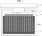
- thermoelectric conversion module causes a temperature difference between both ends of the thermoelectric conversion element by using a heat storage material and includes a thermoelectric conversion element 1, a container 2, a heat storage material 3, and a first heat transfer member 4 as illustrated in FIG. 1 .
- thermoelectric conversion element 1 is also referred to as a thermoelectric conversion device, a thermoelectric element, or a thermoelectric device.
- a thermoelectric conversion module 5 is also referred to as a thermoelectric module, a thermoelectric power generation module, a latent heat usage thermoelectric power generation module, a power source module, a thermoelectric conversion apparatus, or a thermoelectric power generation apparatus.
- the first heat transfer member 4 is also referred to as a heat sink.
- thermoelectric conversion element 1 has, for example, a structure in which a p-type thermoelectric material and an n-type thermoelectric material are alternately arranged and coupled between two substrates on which wiring is formed.
- thermoelectric conversion element 1 is disposed such that one side of the thermoelectric conversion element 1 becomes the heat dissipation side and the other side of the thermoelectric conversion element 1 becomes the heat source side. That is, the first heat transfer member 4 is thermally coupled to the one side of the thermoelectric conversion element 1, and a heat source 7 is thermally coupled to the other side.
- the container 2 is, for example, a heat insulation container made of a heat insulation member such as a resin (for example, a resin container).
- a heat insulation container made of a heat insulation member such as a resin (for example, a resin container).
- the heat insulation container is a container having a high thermal resistance.
- the heat storage material 3 is accommodated in the container 2.
- the heat storage material 3 is a latent heat storage material, and for example, an inorganic hydrated salt such as sodium sulfate hydrate or sodium acetate hydrate, water, an organic compound such as paraffin, or the like may be used.
- a latent heat storage material is also referred to as a liquid-solid phase transition system heat storage material.
- the liquid-solid phase transition system heat storage material is also referred to as a liquid-solid phase transition system latent heat storage material.
- the water has the transition temperature (melting point) of 0 °C, the melting latent heat of 336 kJ/kg, the thermal conductivity of 2.2/0.6 (-10 °C/20 °C) W/mK, and the density of 1.0/0.917 (-10 °C/20 °C) g/cm 3 .
- Sodium sulfate decahydrate as the sodium sulfate hydrate has the transition temperature (melting point) of 32.4 °C, a melting latent heat of 251 kJ/kg, a thermal conductivity of 0.19/0.22 (12 °C/37 °C) W/mK, and a density of 1.39/1.41 (10 °C/40 °C) g/cm 3 .
- Sodium acetate trihydrate as the sodium acetate hydrate has the transition temperature (melting point) of 55 to 58 °C, the melting latent heat of 241/264 kJ/kg, the thermal conductivity of 0.18/0.34 (32 °C/49 °C) W/mK, and the density of 1.39/1.35 (25°C/47 °C) g/cm 3 .
- the paraffin has the transition temperature (melting point) of - 30 °C to 45 °C, the melting latent heat of 150 to 250 kJ/kg, the thermal conductivity of 0.18/0.15 (solid phase/liquid phase) W/mK, and the density of 0.787/0.765 (solid phase/liquid phase) g/cm 3 .
- the first heat transfer member 4 is thermally coupled to the one side of the thermoelectric conversion element 1 and is thermally coupled to the heat storage material 3.
- the first heat transfer member 4 has a thermal conductivity higher than that of the container 2. In this case, heat is transferred to the heat storage material 3 from the heat source through the thermoelectric conversion element 1 and the first heat transfer member 4.
- the first heat transfer member 4 includes a portion that is made of a solid-solid phase transition system heat storage material having a thermal conductivity higher than that of the heat storage material 3 and having a transition temperature different from that of the heat storage material 3.
- the solid-solid phase transition system heat storage material is a latent heat storage material and also referred to as a solid-solid phase transition system latent heat storage material.
- the solid-solid phase transition system heat storage material having a thermal conductivity higher than that of the heat storage material 3 and having a transition temperature different from that of the heat storage material 3 is a solid-solid phase transition system heat storage material including a metal (in particular, a transition metal) as one of components.
- Such a solid-solid phase transition system heat storage material includes, for example, a vanadium oxide (for example, VO 2 compound), BaTiO 3 , and Fe-Co.
- the vanadium oxide has the transition temperature of -100 to 200 °C (for example, 10 °C, 20 °C, 30 °C, 40 °C, or the like), the latent heat of 30 to 60 kJ/kg, the thermal conductivity of 5 W/mK, and the density of 4.3 g/cm 3 .
- BaTiO 3 has the transition temperature of 130 °C, the thermal conductivity of 6 W/mK, and the density of 6.02 g/cm 3 .
- Fe-Co has the transition temperature of 700 to 1000 °C, the thermal conductivity of 10W/mK, and the density of 8g/cm 3 .
- the solid-solid phase transition system heat storage material may function as a heat transfer member that has a thermal conductivity higher than that of the heat storage material 3. Therefore, it is assumed that the heat storage material 3 is accommodated in the container 2, and the first heat transfer member 4 is used to transfer the heat from the heat source 7 to the heat storage material 3 through the thermoelectric conversion element 1, and the first heat transfer member 4 includes a portion made of the solid-solid phase transition system heat storage material.
- the solid-solid phase transition system heat storage material functions as a heat storage material and also functions as a heat transfer member.
- the thermoelectric conversion module increases the amount of power generation without causing an increase in the size.
- the first heat transfer member 4 includes a base part 4A thermally coupled to the one side of the thermoelectric conversion element 1 and fins 4B thermally coupled to the heat storage material 3, and each of the base part 4A and the fin 4B is made of a solid-solid phase transition system heat storage material.
- the whole first heat transfer member 4 is made of the solid-solid phase transition system heat storage material. That is, the first heat transfer member 4 is an integrally-molded body formed by integrating the base part 4A and the fins 4B made of the solid-solid phase transition system heat storage material.
- the fin 4B is also referred to as a heat dissipation fin or a heat radiator. In addition, it is assumed that the fin 4B includes a pin.
- the fin 4B is disposed so as to protrude from the surface of the base part 4A, and the whole fin 4B and the whole base part 4A are accommodated in the container 2.
- the base part 4A is not in contact with the heat storage material 3 and the fin 4B is immersed in and thermally coupled to the heat storage material 3.
- at least a part of the fin 4B included in the first heat transfer member 4 thermally coupled to the thermoelectric conversion element 1 is immersed in the heat storage material 3.
- the first heat transfer member 4 is immersed in the heat storage material 3 and includes the fin 4B that extends in the direction away from the thermoelectric conversion element 1.
- the fin 4B included in the first heat transfer member 4 in contact with the thermoelectric conversion element 1 is inserted into the heat storage material 3, and therefore, the efficiency of heat conduction to the heat storage material 3 may be improved.
- the base part 4A and the heat storage material 3 are spaced apart from each other so as not to be in contact with each other. This is because the base 4A stores more heat since the base part 4A is closest to the heat source 7 and has a large volume, and, if the base part 4A is in contact with the heat storage material 3, first, melting is started from the heat storage material 3 in contact with the base part 4A, and then the sensible heat appears to increase the temperature of the heat storage material 3.
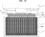
- the embodiment is not limited to such a case, and for example, a resin plate as a heat insulation member may be inserted between the base part 4A and the heat storage material 3 (for example, see FIG. 10 ).
- the first heat transfer member 4 includes the base part 4A thermally coupled to the one side of the thermoelectric conversion element 1 and the fin 4B thermally coupled to the heat storage material 3, the base part 4A is made of a solid-solid phase transition system heat storage material, and the fin 4B is made of a material different from the solid-solid phase transition system heat storage material.
- the fin 4B is made of a high thermal conductivity material such as a metal, for example, aluminum.
- the first heat transfer member 4 includes the base part 4A thermally coupled to the one side of the thermoelectric conversion element 1 and the fin 4B thermally coupled to the heat storage material 3, the fin 4B is made of a solid-solid phase transition system heat storage material, and the base part 4A is made of a material different from the solid-solid phase transition system heat storage material.
- the base part 4A is made of a high thermal conductivity material such as a metal, for example, aluminum.
- the whole first heat transfer member 4 is made of a solid-solid phase transition system heat storage material, is immersed in the heat storage material 3, and directly coupled to the heat storage material 3, and thus the first heat transfer member 4 is thermally coupled to the heat storage material 3.
- the first heat transfer member 4 may be formed so as to be integrated with the fin 4B or may not include the fin 4B.
- the whole first heat transfer member 4 is made of a solid-solid phase transition system heat storage material
- a heat insulation member (for example, resin member) 14 is disposed between the heat storage material 3 and the first heat transfer member 4
- a fin 15 is disposed so as to penetrate the heat insulation member 14, thermally couple the heat storage material 3 and the first heat transfer member 4, and is made of a material different from the solid-solid phase transition system heat storage material.
- the fin 15 is, for example, made of a high thermal conductivity material such as a metal, for example, aluminum.
- the heat insulation member 14 may not be disposed in the thermoelectric conversion module.
- the heat insulation member 14 when the heat insulation member 14 is disposed in the thermoelectric conversion module, it may be suppressed that the melting starts from a portion of the heat storage material 3, which is directly in contact with the first heat transfer member 4, and then the sensible heat appears to increase the temperature of the heat storage material 3.
- a second heat transfer member 6 that has a thermal conductivity higher than that of the container 2 may be accommodated in the container 2.
- the second heat transfer member 6 is, for example, made of a high thermal conductivity material such as a metal.
- the thermoelectric conversion element 1 is accommodated in the container 2, and the other side of the thermoelectric conversion element 1, that is, a side opposite to the side thermally coupled to the first heat transfer member 4, is thermally coupled to the second heat transfer member 6.
- the second heat transfer member 6 is also referred to as a heat transfer component.
- the second heat transfer member 6 is disposed in an opening of the container 2, and the second heat transfer member 6 is thermally coupled to the external heat source 7, and the heat from the heat source 7 outside the container is transferred to the thermoelectric conversion element 1 through the second heat transfer member 6, and then transferred to the first heat transfer member 4 through the thermoelectric conversion element 1, and therefore, the heat is transferred from the first heat transfer member 4 to the heat storage material 3.
- a substrate 10 includes an opening 10A and on which an electronic component 9 is mounted.
- the thermoelectric conversion element 1 is disposed in the opening 10A of the substrate 10 and is electrically coupled to the substrate 10.
- the substrate 10 is coupled to an external connection terminal 11.
- the substrate 10 is also referred to as a circuit board.
- thermoelectric material 3 A case in which a liquid-solid phase transition system heat storage material is used as the heat storage material 3 is described below in detail as an example.
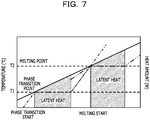
- FIG. 7 is a diagram illustrating relationships between the amounts of latent heat and temperatures changes in the solid-solid phase transition system heat storage material and the liquid-solid phase transition system heat storage material.
- V OC Z ⁇ T ⁇ T 1
- thermoelectric conversion element As “T” continues to rise, “T-T1" becomes large, and the amount of power generation is increased by the thermoelectric conversion element.
- a liquid-solid phase transition heat storage material has a low thermal conductivity and a large thermal resistance, and therefore, the liquid-solid phase transition system heat storage material functions as a heat insulation member while the latent heat of the solid-solid phase transition system heat storage material is used, and therefore, the latent heat may be efficiently used.
- phase transition of the solid-solid phase transition system heat storage material ends, that is, when the amount of the latent heat is exhausted, "TI>T1" is satisfied, and the temperature rises (see the dot dash line in FIG. 7 ).
- thermoelectric conversion element the thermal resistance of the thermoelectric conversion element
- thermal resistance of the solid-solid phase transition system heat storage material R sol .
- the size of the open circuit voltage Voc is set depending on the thermal resistance R sol of the solid-solid phase transition system heat storage material.
- a desired volume and a thermal resistance at that time are calculated by setting the amount of latent heat desired for the solid-solid phase transition system heat storage material at 50000J.
- the thermal resistance R sol is 0.58K/W, which is very small, and therefore, a large open circuit voltage is obtained, and the large amount of power generation is also obtained.
- the solid-solid phase transition system heat storage material may function as a heat transfer member (heat transfer component) to the liquid-solid phase transition system heat storage material 3 outside the latent heat usable temperature range of the solid-solid phase transition system heat storage material by using the latent heat of the solid-solid phase transition system heat storage material and the low thermal resistance.
- the thermal resistance R sol is 21.65 K/W which is 37 times larger than the case in which the vanadium oxide is used, and therefore, the open circuit voltage becomes small, and the amount of the power generation is decreased.
- thermoelectric conversion element the thermoelectric conversion element
- the thermal resistance is large, and therefore, the heat loss is large, and it is difficult to efficiently transfer the heat from the thermoelectric conversion element to the heat storage material.
- the liquid-solid phase transition system heat storage material such as the paraffin function as a heat transfer member in the case in which two types of heat storage materials having different transition temperatures are used.
- thermoelectric conversion module in the thermoelectric conversion module according to the embodiment, there is an effect in which the amount of power generation is increased without causing an increase in the size of the thermoelectric conversion module.
- thermoelectric conversion module 5 a latent heat usable temperature area of the thermoelectric conversion module 5 is expanded, and the amount of power generation per one thermoelectric conversion module 5 is increased.
- thermoelectric conversion module 5 is a highly efficient latent usage thermoelectric power generation apparatus that enables efficient usage of latent heat of at least two types of heat storage materials having different transition temperatures.
- thermoelectric conversion element 1 Heat is transferred to the solid-solid phase transition system heat storage material that constitutes the first heat transfer member 4 through the thermoelectric conversion element 1 by heating from the heat source 7, however, the temperature of the solid-solid phase transition system heat storage material does not change so much until the transition heat is used, and therefore, in the thermoelectric conversion element 1, the large amount of power generation is obtained increased due to a large temperature difference between the heat source 7 and the solid-solid phase transition system heat storage material that constitutes the first heat transfer member 4.
- the temperature of the solid-solid phase transition system heat storage material that constitutes the first heat transfer member 4 changes in accordance with a temperature change in the heat source 7, however the heat storage material has a high heat transfer property, and therefore, the thermal resistance of the heat storage material is small, and transfer of the heat from the thermoelectric conversion element 1 to the heat storage material 3 is not suppressed.
- the temperature of the heat storage material 3 does not change so much because of usage of the latent heat, and therefore, in the thermoelectric conversion element 1, the large amount of power generation is obtained due to a large temperature difference between the heat storage material 3 and the heat source 7.
- thermoelectric conversion element 1 may be generated even when it is day or night using the thermoelectric conversion element 1 under an environment where the temperature difference between one surface and the other surface of a structure body of the thermoelectric conversion element 1 is reversed at day and night such as a manhole.
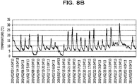
- FIG. 8A illustrates a temperature change in the lid of the manhole, which is measured from May 22 to May 30, and FIG. 8B illustrates a temperature change in the lid of the manhole, which is measured from February 3 to March 3.
- thermoelectric power generation using the temperature of the lid of the manhole power generation using a difference between the temperature of the lid of the manhole and the temperature in the manhole is conceived, however, in the power generation using not a heat storage material but only a heat sink, a temperature difference generated in the thermoelectric conversion element is much smaller than the temperature difference between the temperature of the lid of the manhole and the temperature in the manhole. Thus, only the small amount of power generation is obtained.
- a temperature difference generated in the thermoelectric conversion element becomes the temperature difference between the lid of the manhole and the temperature of the heat storage material, which is large, and therefore, the large amount of power generation is obtained. For example, the sufficient amount of power generation desired for a manhole sensor assumed for data transmission by wireless communication is obtained. In addition, the large amount of power generation is obtained without deterioration through aging.
- thermoelectric conversion element is mainly constituted by two or more p-type thermoelectric semiconductors and n-type thermoelectric semiconductors, and has a function to directly convert heat energy into electric energy and directly convert electric energy into heat energy.
- a temperature difference is applied to both ends of the thermoelectric conversion element, a voltage is generated by the Seebeck effect. Extraction of such a voltage as electric energy is performed by a thermoelectric power generation apparatus.
- thermoelectric power generation apparatus allows direct energy conversion from heat energy to electric energy, and therefore, the thermoelectric power generation apparatus has been attracting attention as one of valid usage methods of heat energy typified by waste heat usage.
- thermoelectric conversion element has a structure in which a thermoelectric pair is formed by pairing a pillar-shaped p-type thermoelectric semiconductor and n-type thermoelectric semiconductor having substantially the same length at both ends of the thermoelectric conversion element, and two or more thermoelectric pairs are arranged in a planar manner such that the p-type thermoelectric semiconductors and the n-type thermoelectric semiconductors are alternately arranged in a regular pattern, and the thermoelectric pairs are electrically coupled in series.
- Wiring that realizes electrical connection is, for example, formed on two substrates made of Si or a ceramic material, and the substrate has a structure in which the substrates face each other with gaps corresponding to the thickness of the p-type thermoelectric semiconductor and the n-type thermoelectric semiconductor and an electrode that connects the thermoelectric semiconductors.
- thermoelectric semiconductor pair One of the substrates is brought into contact with the heat source (heat generation source) and the other substrate releases the heat, and therefore, a temperature difference is generated in the thermoelectric semiconductor pair.
- heat generation source heat generation source
- a heat radiating component is attached to the substrate on the heat radiation side.
- thermoelectric conversion element The power generation by the thermoelectric conversion element may be performed anywhere as long as there is a temperature difference; however, the power generation depends on a naturally-controlled temperature, which is left to natural devices.
- thermoelectric conversion element when a concrete or a metal to be heated by solar heat is selected as a heat source, and a thermoelectric conversion element is attached thereto, the heat from heat source is dissipated to the atmosphere through the heat sink to generate a temperature difference in the thermoelectric conversion element and generate electricity.
- thermoelectric conversion module even when the surface area of a fin of the heat sink is increased, it is difficult to maintain the temperature on the side of the thermoelectric conversion element, on which the heat sink is disposed the same as the outside air temperature.
- thermoelectric conversion module a temperature difference generated between the upper and lower surfaces of the thermoelectric conversion element becomes smaller than the temperature difference between the outside air temperature and the high temperature heat source. Therefore, the amount of power generated by the thermoelectric conversion module also decreases.
- thermoelectric conversion modules each of which causes a temperature difference in a thermoelectric conversion element by using a change over time in the temperature of a heat source.
- the heat source is brought into contact with on one surface of the thermoelectric conversion elements, and a heat storage material is brought into contact with on the other surface.
- a heat source the temperature of which is not fixed and changes over time is used.
- a motor or a boiler that intermittently repeats operation and pause is used as the heat source.
- a thing left outside such as an exterior wall or a roof of a building or an engine or an exterior of a vehicle such as an automobile is used as the heat source.
- the heat storage material may be made of an organic or inorganic material, however, what is commonly used for the heat storage material is a saturated hydrocarbon type organic matter which is relatively easy to handle.
- the melting point of the heat storage material ranges various temperatures from -30 °C to 40 °C, and the heat storage material is used for air cooling and has been considered to be applied as a building material.
- the heat storage material has a property of maintaining a fixed temperature due to the phase change in the material. Therefore, as the temperature of the heat source changes over time, a temperature difference is caused between the heat source and the heat storage material, and the thermoelectric conversion element generates electricity in accordance with this temperature difference.
- the heat storage material undergoes the phase transition due to the heat transmitted from the heat source through the thermoelectric conversion element, however a fixed temperature is maintained in the heat storage material during the phase transition. Therefore, in a case in which the heat exchange with members other than the heat source is negligible in the whole the thermoelectric conversion module, when an integral value of the amount of the heat flowing into the heat storage material from the heat source through the thermoelectric conversion element reaches a latent heat amount of the heat storage material, the phase transition is completed.
- the integral value exceeds the amount of latent heat of the heat storage material, the temperature of the heat storage material changes in accordance with the amount of the flowing heat depending on the heat capacity, and it becomes difficult to cause a temperature difference between the upper and lower surfaces of the thermoelectric conversion element.
- thermoelectric conversion module In such a type of the thermoelectric conversion module, a temperature difference is caused between the upper and lower surfaces of the thermoelectric conversion element by using thermal conduction between the heat storage material and the thermoelectric conversion element or between the heat source surface and the thermoelectric conversion element. Thus, as compared with a thermoelectric conversion module having a type that uses heat transfer with the outside air, a temperature difference is caused reliably.
- the heat storage material works most effectively, and therefore, it is difficult to fully demonstrate the strength in the heat source in which the average temperature changes.
- a building that is installed outdoors and heated by the radiant heat of the sun is conceived as such a heat source.
- the temperature of the building exposed to the sun rises with the sunrise and falls after the peak around daytime, and the daily temperature cycle is repeated with the temperature in the early dawn as the lowest temperature, however, since the radiant heat of the sun varies according to the season, and therefore, the average temperature changes.
- thermoelectric conversion module becomes large n this case.
- thermoelectric conversion module to increase the amount of power generation without increasing in the size of the thermoelectric conversion module, as described above, two types of heat storage materials having different transition temperature (operation temperature) are used, and a solid-solid phase transition system heat storage material is used as one of the heat storage materials, and the heat storage material 3 is accommodated in the container 2, and the first heat transfer member 4 is used to transfer the heat from the heat source 7 to the heat storage material 3 through the thermoelectric conversion element 1, and the first heat transfer member 4 includes a portion made of a solid-solid phase transition system heat storage material.
- thermoelectric conversion modules including n thermoelectric conversion elements respectively corresponding to the n types of heat storage materials when n thermoelectric conversion modules including n thermoelectric conversion elements respectively corresponding to the n types of heat storage materials are prepared, the cost increases n times, and the space also increases n times, which is not preferable.
- thermoelectric conversion module it is conceivable to use two or more liquid-solid phase transition system heat storage materials having different transition points for one thermoelectric conversion module, mix the materials, and put the materials in the container, however, as compared with the case in which a liquid-solid phase transition system heat storage material is used alone, the melting points do not clearly appear, and the effect of latent heat usage decreases, which is not preferable.
- thermoelectric conversion elements are disposed in the respective spaces, the cost increases, and a large space is to be prepared, which is not preferable.
- open circuit voltages output from the respective thermoelectric conversion elements are different, and therefore, the thermoelectric conversion elements are to be electrically coupled to each other to combine the outputs to use the thermoelectric conversion elements for a single thermoelectric conversion module, however, the electromotive forces are different and unstable, thereby being difficult to achieve as in the example.
- a liquid-solid phase transition system heat storage material in which the melting point is a transition point is used.
- Such a heat storage material has a very low thermal conductivity, and it is known that a representative value of the thermal conductivity is about 0.1 to 0.6 W/mK.
- thermoelectric conversion element Even when the heat storage material is brought into contact with the thermoelectric conversion element, only a portion of a heat storage material portion, which is adjacent to the thermoelectric conversion element, is repeatedly melted and solidified. As a result, the heat is not conducted up to a portion of a heat storage material, which is away from the thermoelectric conversion element, and it is difficult to derive the performance of the whole heat storage material.
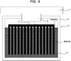
- thermoelectric conversion module in a thermoelectric conversion module as illustrated in FIG. 9 , in a metal heat sink 4X including a fin 4XB and a base part 4XA, the fin 4XB is inserted into the heat storage material 3, and therefore, the efficiency of heat conduction with the heat storage material 3 is improved.
- the two or more fins 4XB are brought into contact with the thermoelectric conversion element 1 and inserted into the heat storage material 3 in parallel with each other. More specifically, each of the fins 4XB is inserted into the heat storage material 3 up to a predetermined depth from above.
- the fins 4XB are inserted into the heat storage material 3 as described above, and therefore, a portion of the heat storage material 3, which is melted, travels from the upper surface side to the lower side along the fins 4XB. As a result, the heat storage material 3 is liable to melt in a wider area.
- the first heat transfer member 4 is immersed in the heat storage material 3, and the fin 4B is disposed so as to extend in a direction away from the thermoelectric conversion element 1 to achieve efficient improvement of heat conduction to the heat storage material 3.
- the heat sink 4 that includes the fin 4B and the base part 4A and is made of a solid-solid phase transition system heat storage material is used instead of the metal heat sink 4X including the fin 4XB and the base part 4XA, and therefore, the amount of power generation is increased without increasing the size of the thermoelectric conversion module 5, and the efficiency of heat conduction to the heat storage material 3 is improved.
- the second heat transfer member 6 is included in the container 2, and the thermoelectric conversion element 1 is accommodated in the container 2, and the other side of the thermoelectric conversion element 1 is thermally coupled to the second heat transfer member 6, however, the embodiment is not limited to such a case.
- the second heat transfer member 6 may be disposed outside the container (first container) 2, and the thermoelectric conversion element 1 may be disposed outside the container 2, and the other side of the thermoelectric conversion element 1 may be thermally coupled to the second heat transfer member 6.
- the second heat transfer member 6 and the thermoelectric conversion element 1 are disposed outside the container 2, and the fin 4B that constitutes the first heat transfer member 4 is inserted and immersed in the heat storage material 3 accommodated in the container 2, and the base part 4A of the first heat transfer member 4 is disposed outside the container 2.
- thermoelectric conversion element 1 be sealed by a sealing member 12 such that a space is formed around the thermoelectric conversion element 1.
- the thermoelectric conversion element 1 may be sealed by a sealing member such that a space is formed around the thermoelectric conversion element 1.
- thermoelectric conversion element 1 may be disposed outside the container 2 and a third heat transfer member 8 that has a thermal conductivity higher than that of the container 2 is accommodated in the container 2, and the thermoelectric conversion element 1 may be disposed outside the container 2, and one side of the thermoelectric conversion element 1 may be thermally coupled to the first heat transfer member 4 through the third heat transfer member 8, and the other side of the thermoelectric conversion element 1 may be thermally coupled to the second heat transfer member 6. That is, in the above-described embodiment, the thermoelectric conversion element 1 and the second heat transfer member 6 may be disposed outside the container 2, and the one side of the thermoelectric conversion element 1 may be thermally coupled to the first heat transfer member 4 through the third heat transfer member 8.
- the third heat transfer member 8 is disposed in the opening 10A of the substrate 10 accommodated in the container 2, and the thermoelectric conversion element 1 is electrically coupled to the substrate 10, for example, through a connector 13.
- the thermoelectric conversion element 1 sandwiched by the third heat transfer member 8 and the second heat transfer member 6 be sealed by the sealing material 12 such that a space is formed around the thermoelectric conversion element 1.
- the second heat transfer member 6 is thermally coupled to the heat source 7.
- the third heat transfer member 8 is also referred to as a heat dissipation side heat transfer member, and the second heat transfer member 6 is also referred to as a heat source side (heat absorption side) heat transfer member.
- thermoelectric conversion module 5 two types of heat storage materials such that the solid-solid phase transition system heat storage material (first heat storage material) and a liquid-solid phase transition system heat storage material (second heat storage material) are used, and the solid-solid phase transition system heat storage material is used as the first heat transfer member 4 to prepare a thermoelectric conversion module 5 [see FIG. 12A ].
- thermoelectric conversion module 5 the thermoelectric conversion module 5 [see FIG. 12A ].
- thermoelectric conversion module 5 In addition, in a comparative example 1, only a solid-solid phase transition system heat storage material 4 (first heat storage material) is used to prepare the thermoelectric conversion module 5 [see FIG. 12B ].
- thermoelectric conversion module 5 the solid-solid phase transition system heat storage material as the first heat transfer member 4 is coupled to the one side of the thermoelectric conversion element 1, and the aluminum member as the second heat transfer member 6 is coupled to the other side of the thermoelectric conversion element 1 to prepare the thermoelectric conversion module 5 [see FIG. 12B ].
- thermoelectric conversion module 5 In addition, in a comparative example 2, only a liquid-solid phase transition system heat storage material 3 (second heat storage material) is used to prepare the thermoelectric conversion module 5 [see FIG. 12C ].
- the liquid-solid phase transition system heat storage material 3 is accommodated in the resin container 2, and the aluminum heat sink 4X is coupled to the one side of the thermoelectric conversion element 1, and the fin 4XB of the aluminum heat sink 4X is immersed in the liquid-solid phase transition system heat storage material 3 accommodated in the resin container 2.
- the other side of the thermoelectric conversion element 1 is coupled to the aluminum member as the second heat transfer member 6 attached to the resin container 2 to prepare the thermoelectric conversion module 5 [see FIG. 12C ].
- thermoelectric conversion module 5 As the thermoelectric conversion module 5 according to the examples, and the comparative examples 1 and 2, as the thermoelectric conversion element 1, single 9501/127/060B (Seebeck coefficient: 0.057 V/K, electric resistance value: 3.27 ⁇ , and thermal resistance value: 0.45 W/K) manufactured by Ferrotec Corporation is used.
- thermoelectric conversion element 1 single 9501/127/060B (Seebeck coefficient: 0.057 V/K, electric resistance value: 3.27 ⁇ , and thermal resistance value: 0.45 W/K) manufactured by Ferrotec Corporation is used.
- thermoelectric conversion element 1 is heated by a heater through the aluminum member as the second heat transfer member 6.
- the lid of a manhole is assumed. It is known that an average temperature of the lid of the manhole in Tokyo is about 20 °C in spring and autumn, is about 30 to 35 °C in summer, and is about 10 °C in winter, and therefore, the annual average temperature is about 20 °C. Therefore, to check the amount of power generation in spring, autumn, and summer in each of the thermoelectric conversion modules 5 according to the example and the comparative examples 1 and 2, the thermoelectric conversion element 1 is heated by a heater.
- the solid-solid phase transition system heat storage material (first heat storage material) is selected that has the transition point close to 20 °C, which is the annual average lid temperature
- the liquid-solid phase transition system heat storage material (second heat storage material) is selected that has the transition point close to 30 °C, which is the average lid temperature in summer.
- the heat transfer amount 50000J from the manhole in spring and autumn is desired as the latent heat
- 1.25 kgs of a vanadium oxide based latent heat storage material manufactured by Nippon Denko Co., Ltd. having a transition point of 20 °C and a latent heat of 40 kJ/kg is used as the solid-solid phase transition system heat storage material (first heat storage material).
- the heat transfer amount 78000J from the manhole in summer is desired as the latent heat
- the solid-solid phase transition system heat storage material (first heat storage material) is selected that has an annual average lid temperature of 20 °C close to the transition point.
- the amount of latent heat of the solid-solid phase transition system heat storage material (first heat storage material) is set at 78000J in accordance with the amount of heat transfer from the manhole in summer.
- 1.95 kgs of a vanadium oxide-based latent heat storage material manufactured by Nippon Denko Co., Ltd. having a transition point of 20 °C and a latent heat of 40 kJ/kg is used as the solid-solid phase transition system heat storage material (first heat storage material).
- the liquid-solid phase transition system heat storage material (second heat storage material) is selected that has the annual average lid temperature of 20 °C close to the transition point.
- the amount of the latent heat of the liquid-solid phase transition system heat storage material (second heat storage material) is set at 78000J in accordance with the amount of heat transfer from the manhole in summer.
- 360g of Passamo F20 (melting point of 20.6 °C, latent heat of fusion of 220 kJ/kg) manufactured by Kaneka Corporation, which is a paraffin-based heat storage material, is used as the liquid-solid phase transition system heat storage material (second heat storage material).
- thermoelectric conversion modules 5 prepared as described above is heated by a heater to obtain the amount of power generation.
- thermoelectric conversion module 5 in the case of the average lid temperature of 20 °C in spring and autumn, the amount of the power generation is 61.0 J/day, and in the case of the average lid temperature of 30 °C in summer, the amount of the power generation is 82.1 J/day.
- thermoelectric conversion module 5 in the case of the average lid temperature of 20 °C in spring and autumn, the amount of the power generation is 61.4 J/day, and in the case of the average lid temperature of 30 °C in summer, the amount of the power generation is 22 J/day.
- thermoelectric conversion module 5 in the case of the average lid temperature of 20 °C in spring and autumn, the amount of the power generation is 53.7 J/day, and in the case of the average lid temperature of 30 °C in summer, the amount of the power generation is 65.3 J/day.
- thermoelectric conversion module 5 As described above, in any case of the average lid temperature of 20 °C in spring and autumn and the average lid temperature of 30 °C in summer, it has been confirmed that more power is reliably generated in the thermoelectric conversion module 5 according to the example than in the thermoelectric conversion module 5 according to the comparative example 2. In addition, it has been confirmed that, in the case of the average lid temperature of 20 °C in spring and autumn, the amount of the power generation is similar, however, in the case of the average lid temperature of 30 °C in summer, the amount of the power generation considerably increases as compared with the thermoelectric conversion module 5 according to the comparative example 1.
- thermoelectric conversion module 5 in the thermoelectric conversion module 5 according to the example, two types of heat storage materials such as the solid-solid phase transition system heat storage material (first heat storage material) and the liquid-solid phase transition system heat storage material (second heat storage material) are used, and the solid-solid phase transition system heat storage material is used as the first heat transfer member 4, and therefore, it has been confirmed that more electricity is generated annually by using only one thermoelectric conversion module 5 (one thermoelectric conversion element 1) without causing an increase in the size.
- first heat storage material the solid-solid phase transition system heat storage material
- second heat storage material liquid-solid phase transition system heat storage material
- a sensor module and an information processing system according to a second embodiment are described below with reference to FIGs. 13 to 19 .
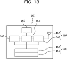
- the sensor module is an integrated module, and as illustrated in FIG. 13 , an integrated module 160 includes a power generation module 161, a power storage module 162, a sensor 163, a controller 164, a memory 165, a communication circuit 166, and an antenna 167.
- thermoelectric conversion module 5 is applied to the power generation module 161. That is, the power generation module 161 includes the thermoelectric conversion element 1, the container 2, the heat storage material 3, and the first heat transfer member 4 including a portion made of a solid-solid phase transition system heat storage material having a thermal conductivity higher than that of the heat storage material 3 and a transition temperature different from that of the heat storage material 3.
- the sensor module includes at least the sensor 163 and the thermoelectric conversion module 5 according to the above-described first embodiment electrically coupled to the sensor 163.
- the power storage module 162 is coupled to the power generation module 161 and stores electric power generated in the power generation module 161. It is sufficient that the power storage module 162 has a function to store electric power.
- the storage module 162 for example, an all solid-state secondary battery is preferable from the viewpoint of space-saving and safety.
- the power generation module 161 and the power storage module 162 constitute an electric power supply unit 168. Electric power is supplied to the sensor 163, the controller 164, and the communication circuit 166 from at least one of the power generation module 161 and the power storage module 162 that constitute the electric power supply unit 168. When stable power is supplied from the power generation module 161, the power storage module 162 may be omitted.
- the senor 163 may a sensor detects the temperature, humidity, pressure, light, sound, electromagnetic wave, acceleration, vibration, gas, fine particles, or the like.
- the sensor 163 may be a distance measuring sensor that emits infrared rays to an object and measures a distance to the object in accordance with received light reflected from the object, a weight sensor that measures the weight of the object, or a water level sensor that detects data such as a water level or the like.
- the controller 164 transmits, for example, various pieces of data that have been detected by the sensor 163 to a server 175 that is not illustrated through the communication circuit 166 and the antenna 167.
- the controller 164 may transmit, to the server 175, the various pieces of data that have been detected by the sensor 163 and secondary data based on another data.
- the controller 164 may execute certain calculation, for example, by using the various pieces of data that have been detected by the sensor 163 to calculate secondary data and transmits the secondary data to the server 175.
- the memory 165 stores the various pieces of data that have been detected by the sensor 163 and the calculated secondary data in response to an instruction of the controller 164.
- the stored information is read in response to an instruction of the controller 164.
- the communication circuit 166 and the antenna 167 constitute a communication unit 169.
- the communication unit 169 performs transmission and reception of data between the controller 164 and the server 175.
- a wireless communication using the antenna 167 is used, however, a wired communication may be used instead of the wireless communication.
- the above-described integrated module 160 is applied, for example, to an information processing system 170 according to the embodiment as illustrated in FIG. 14 .
- the information processing system 170 includes the two or more integrated modules 160 and the server 175. That is, the information processing system 170 includes the above-described integrated modules (sensor modules) 160 and the server (computer) 175 that processes pieces of data obtained by the integrated modules 160.
- the information processing system 170 is a system that processes pieces of information obtained from manholes 176.
- the two or more integrated modules 160 are installed in the respective manholes 176.
- the two or more integrated modules 160 respectively installed in the two or more manholes 176 are coupled to the server 175 through a network 177.
- data may be transmitted through a short-range wireless communication from the integrated module 160 to the server 175 each time a vehicle including the server 175 travels and approaches the integrated module 160 installed in each manhole 176.
- the integrated module 160 may be installed in any structure body of the manhole 176.
- the integrated module 160 is fixed to a lid 178, a concrete pipe 179, or the like that is a structure body of the manhole 176 depending on a detection target of the sensor 163 or the type of the sensor 163.
- a thermoelectric conversion element included in the integrated module 160 is thermally coupled to the structure body of the manhole 176, and power is generated due to a temperature difference between the structure body of the manhole 176 and the outside air or the internal temperature of the manhole 176.
- the information processing system 170 is used for understanding deterioration of the structure body (the lid 178 or the concrete pipe 179) of the manhole 176.
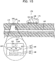
- the sensor 163 detects the temperature and the humidity in the manhole 176, the vibration (acceleration) acting on the structure body of the manhole 176, and the data detected by the sensor 163 is accumulated in the memory 165.
- the controller 164 transmits data accumulated in the memory 165 through the communication circuit 166 and the antenna 167.
- the server 175 disposed in the vehicle 180 for measurement collects the data.
- the server 175 displays the collected data on a map displayed on an in-vehicle monitor by using location information of the vehicle 180 by a global positioning system (GPS) and the collected data.
- the degree of deterioration of the concrete pipe 179 in each of the manholes 176 may be estimated from displayed information indicating the temperature, the humidity, the vibration, and the like.
- a camera 182 that captures an image of the lid 178 of the manhole 176 is attached to the bottom of the vehicle 180 for measurement together with a reception apparatus 181, and therefore, deterioration of the lid 178 (iron part) of the manhole 176 may be determined by image recognition.
- a replacement timing of the lid 178 of the manhole 176 may be sold to a local government as information.
- the vehicle that collects data may not be a special vehicle for measurement, but for example, may be a garbage collection vehicle operated by the local government.
- the reception apparatus 181 and the camera 182 are installed at the bottom of the garbage collection vehicle, and therefore, data may be collected regularly without collection expense.
- the senor 163 may detect the concentration of gas generated in the manhole 176.
- the gas generated in the manhole 176 includes for example, hydrogen sulfide gas. It is known that hydrogen sulfide gas generated in the sewer 183 rapidly deteriorates the structure body of the manhole 176. The generation of the hydrogen sulfide gas also causes complaints of neighborhood residents. A hydrogen sulfide gas sensor is used as the sensor 163, thereby promptly responding to the complaints of the neighborhood residents as well as improving the prediction accuracy of deterioration of the structure body of the manhole 176.
- the senor 163 is a sensor that detects at least one of the temperature, the humidity, and the vibration in the manhole 176, and the concentration of gas generated in the manhole 176.
- the integrated module 160 is implemented as a module obtained by sealing the electronic component such as the sensor 163 and the thermoelectric conversion element with resin, thereby maintaining the long-term reliability.
- the information processing system 170 is used for predicting the flow rate of the sewer 183 coupled to the manhole 176.
- the sensor 163 for example, a water level gauge or a flow meter is used.
- the sensor 163 that is the water level gauge or the flow meter is installed in the manhole 176, and therefore, the water level or the flow rate of the sewage 183 is allowed to be grasped with fine details.
- the sensor 163 is incorporated in the integrated module 160, however, for example, instead of the sensor 163, a sensor control unit that controls operation of an external sensor may be used.
- the sensor control unit may control a sensor that is not illustrated such as a water level gauge or a flow meter disposed in the sewage 183 and acquire information detected by the sensor.
- the information detected by the sensor may be transmitted to the sensor control unit wirelessly.
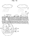
- the water level or the flow rate of the sewer 183 is detected by the sensor 163 once a day or once an hour, and the data detected by the sensor 163 is collected into the server 175 of the data center 184 through a high-speed communication line.
- the water level or the flow rate data of the sewage 183 detected by the sensor 163 may be transmitted at the same time as the measurement or may be transmitted after data for one day or one week has been accumulated to reduce the power consumption. Similar to the first application example, the vehicle for measurement may collect the data.
- a relationship between a weather phenomenon and the water level or the flow rate of the sewer 183 is also established from the analysis result of the data of the water level or the flow rate of the sewer 183 and the rainfall data of the Meteorological Agency.
- the water level or the flow rate of the sewage 183 in various places may be estimated from the rainfall data of the Meteorological Agency, and the provision and distribution of the prediction data may be changed.
- the water level and the flow rate of the sewer 183 change year by year depending on a housing construction, a living condition, or a land development situation, and therefore, the information processing system 170 that is allowed to continuously update data is useful.
- the information processing system 170 may also be used for measuring the water level or the flow rate of the sewer 183 in the event of locally-concentrated heavy rain or the like.
- the information processing system 170 may also be used for measuring the water level or the flow rate of the sewer 183 in the event of locally-concentrated heavy rain or the like.
- the controller 164 sequentially transmits the data to the server 175 through the communication circuit 166 and the high-speed communication line.
- the server 175 may cause smartphones or tablets of a worker and a resident in the vicinity of a flood site to issue an alarm.
- the vehicle for measurement may be parked on a specific manhole 176 to collect data by the server installed in the vehicle through a near field communication.
- the information processing system 170 is used for security and work history of the manhole 176.
- the sensor 163 detects opening/closing of the lid 178 of the manhole 176.
- an acceleration sensor or an opening/closing switch is used as the sensor 163 for example. It is sufficient that the sensor 163 detects at least one of the acceleration generated in the lid 178 of the manhole 176 and the opening/closing state of the lid 178 of the manhole 176 on order to detect the opening/closing of the lid 178 of the manhole 176.
- Data (signal) output from the sensor 163 in response to the opening/closing of the lid 178 of the manhole 176 is received at the server 175.
- security measurements for example, measurement for terrorism through explosion devices
- operation history in a cleaning work of the sewer 183 is checked.
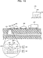
- the information processing system 170 is used for acquiring road traffic information.
- the sensor 163 detects vehicles 185, 186, and 187 that pass over the manhole 176.
- this sensor 163 for example, an acceleration sensor, a magnetic sensor, a microphone, or the like is used. Signal corresponding to the number of vehicles that pass over the manhole 176 are obtained from the sensor 163. The data (signal) output from the sensor 163 is received at the server 175.
- congestion information even on narrow roads, alleys, or the like, which is not measured in the current road traffic information communication system may be obtained. Therefore, detailed congestion information may be provided.
- the type of the vehicle 185, 186, or 187 that pass over the manhole 176 may be detected from the strength of a detected value of the sensor 163.
- a data set obtained by associating a detected value of the sensor 163 with the type of a vehicle is stored in the memory 165 in advance.
- the controller 164 determines the type of the vehicle from the detected value of the sensor 163 and the above-described data set and transmits the vehicle type information to the server 175. As a result, the type of vehicle that passes over the manhole 176 is grasped.
- individual identification information of the vehicle 185, 186, or 187 that pass over the manhole 176 may be detected by the sensor 163.
- a characteristic of the vehicle may be obtained by a reaction of the magnetic sensor. That is, for example, a medium that emits certain magnetic specific to a car is installed in each vehicle, and therefore, the vehicle may be identified. Analysis of a difference of the movement of a car in a city based on the type of the car leads to city evaluation and urban road control such as planning to guide a specific vehicle to a specific road.
- the senor 163 detects at least one of the number of vehicles that pass over the manhole 176, types of the vehicles, and individual identification information.
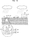
- the information processing system 170 is used for measuring rainfall.
- an X band radar for weather prediction is used. Radio waves of the X band radar do not reach a heavy rain area, for example, in the event of heavy rain and does not get across a large object such as a mountain. Also, it may be difficult for the current radar to find and track a heavy rain area where the sudden occurrence or sudden development of the heavy rain appears. High temporal and spatial resolution are desired for the high accuracy prediction.
- the resolution of the X band radar is 250 m, however, when the sensors 163 are installed in the manholes 176 at average intervals of over 30 m, it is conceivable that far more detailed meteorological observation is performed, thereby being useful for measurement and prediction of locally-concentrated heavy rain or the like.
- Data (signal) output from the sensor 163 is received at the server 175.
- the dedicated server 175 is used, however, a general-purpose computer may be used as the server 175.
- a program that causes the general-purpose computer that functions as the server 175 to execute operations performed by the controller 164 and the server 175 may be installed and executed.
- the program may be supplied through a recording medium or may be downloaded from a network.
Landscapes
- Engineering & Computer Science (AREA)
- Physics & Mathematics (AREA)
- Mechanical Engineering (AREA)
- Thermal Sciences (AREA)
- General Engineering & Computer Science (AREA)
- General Physics & Mathematics (AREA)
- Chemical & Material Sciences (AREA)
- Analytical Chemistry (AREA)
- Computer Networks & Wireless Communication (AREA)
- Cooling Or The Like Of Electrical Apparatus (AREA)
- Electromechanical Clocks (AREA)
Abstract
Description
- The present invention relates to a thermoelectric conversion module, a sensor module, and an information processing system.
- For example, it is promising to use environmental power generation in which a power line and a signal line that poses problems in construction of a sensor network are unnecessary. As the environmental power generation, power generation using a thermoelectric conversion element that generates electricity due to a temperature difference is effective in addition to solar power generation.
- For example, there is a technology that causes a temperature difference in a thermoelectric conversion element by using a change over time in the temperature of a heat source. In this case, the heat source is brought into contact with one side of the thermoelectric conversion element, and a heat storage material is brought into contact with the other side. In addition, as the temperature of the heat source changes over time, a temperature difference is generated between the heat source and the heat storage material, and the thermoelectric conversion element generates electricity in accordance with the temperature difference.
- In addition, for example, there is a technology that uses two or more heat storage materials having different operating temperatures to increase the amount of power generation.
-
- PTL 1: International Publication Pamphlet No.
WO2012/133790 - PTL 2: International Publication Pamphlet No.
WO2013/099943 - When two or more heat storage materials having different operating temperatures are used to increase the amount of power generation, it is conceivable to place the two or more heat storage materials in different containers such that heat is transferred to the heat storage materials through the respective containers.
- However, this causes an increase in the size of the thermoelectric conversion module.
- The technology discussed herein aims at increasing the amount of power generation without increasing the size of the thermoelectric conversion module.
- In one aspect, a thermoelectric conversion module includes a thermoelectric conversion element, a container, a heat storage material accommodated in the container, a first heat transfer material thermally coupled to one side of the thermoelectric conversion element and thermally coupled to the heat storage material, and the first heat transfer member includes a portion made of a solid-solid phase transition system heat storage material having a thermal conductivity higher than that of the heat storage material and having a transition temperature different from that of the heat storage material.
- In addition, in one aspect, a sensor module includes a sensor and the above-described thermoelectric conversion module electrically coupled to the sensor.
- In addition, in one aspect, an information processing system includes the above-described sensor module and a computer that processes data obtained through the sensor module.
- As one aspect, there is an effect in which the amount of the power generation is increased without causing an increase in size of the thermoelectric conversion module.
-
-
FIG. 1 is a schematic cross-sectional view illustrating a configuration of a thermoelectric conversion module according to a first embodiment. -
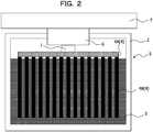
FIG. 2 is a schematic cross-sectional view illustrating a configuration of a modification of the thermoelectric conversion module according to the first embodiment. -
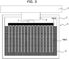
FIG. 3 is a schematic cross-sectional view illustrating a configuration of a modification of the thermoelectric conversion module according to the first embodiment. -
FIG. 4 is a schematic cross-sectional view illustrating a configuration of a modification of the thermoelectric conversion module according to the first embodiment. -
FIG. 5 is a schematic cross-sectional view illustrating a configuration of a modification of the thermoelectric conversion module according to the first embodiment. -
FIG. 6 is a schematic cross-sectional view illustrating a configuration of the thermoelectric conversion module according to the first embodiment. -
FIG. 7 is a diagram illustrating relationships between temperature changes and amounts of latent heat of a solid-solid phase transition system heat storage material and a liquid-solid phase transition system heat storage material in the thermoelectric conversion module according to the first embodiment. -
FIG. 8A is a diagram illustrating a temperature change in a lid of a manhole, which is measured from May 22 to May 30. -
FIG. 8B is diagram illustrating a temperature change in the lid of a manhole, which is measured on February 3 to March 3. -
FIG. 9 is a schematic cross-sectional view illustrating a configuration of a thermoelectric conversion module using a metal heat sink. -
FIG. 10 is a schematic cross-sectional view illustrating a configuration of a modification of the thermoelectric conversion module according to the first embodiment. -
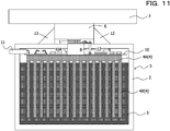
FIG. 11 is a schematic cross-sectional view illustrating a configuration of a modification of the thermoelectric conversion module according to the first embodiment. -
FIG. 12A is a schematic cross-sectional view illustrating a configuration of a thermoelectric conversion module according to an example 1. -
FIG. 12B is a schematic cross-sectional view illustrating a configuration of a thermoelectric conversion module according to a comparative example 1. -
FIG. 12C is a schematic cross-sectional view illustrating a configuration of a thermoelectric conversion module according to a comparative example 2. -
FIG. 13 is a schematic diagram illustrating a configuration of a sensor module according to a second embodiment. -
FIG. 14 is a schematic diagram illustrating a configuration of an information processing system using the sensor module according to the second embodiment. -
FIG. 15 is a schematic diagram illustrating a first application example of the sensor module and the information processing system according to the second embodiment. -
FIG. 16 is a schematic diagram illustrating a second application example of the sensor module and the information processing system according to the second embodiment. -
FIG. 17 is a schematic diagram illustrating a third application example of the sensor module and the information processing system according to the second embodiment. -
FIG. 18 is a schematic diagram illustrating a fourth application example of the sensor module and the information processing system according to the second embodiment. -
FIG. 19 is a schematic diagram illustrating a fifth application example of the sensor module and the information processing system according to the second embodiment. - A thermoelectric conversion module, a sensor module, and an information processing system according to embodiments of the technology discussed herein are described below with reference to the drawings.
- First, a thermoelectric conversion module according to an embodiment is described with reference to
FIGs. 1 to 12 . - The thermoelectric conversion module according to the embodiment is used for power generation using a thermoelectric conversion element that generates electricity due to a temperature difference in environmental power generation.
- The thermoelectric conversion module according to the embodiment causes a temperature difference between both ends of the thermoelectric conversion element by using a heat storage material and includes a
thermoelectric conversion element 1, acontainer 2, aheat storage material 3, and a firstheat transfer member 4 as illustrated inFIG. 1 . - The
thermoelectric conversion element 1 is also referred to as a thermoelectric conversion device, a thermoelectric element, or a thermoelectric device. In addition, athermoelectric conversion module 5 is also referred to as a thermoelectric module, a thermoelectric power generation module, a latent heat usage thermoelectric power generation module, a power source module, a thermoelectric conversion apparatus, or a thermoelectric power generation apparatus. In addition, the firstheat transfer member 4 is also referred to as a heat sink. - Here, the
thermoelectric conversion element 1 has, for example, a structure in which a p-type thermoelectric material and an n-type thermoelectric material are alternately arranged and coupled between two substrates on which wiring is formed. In addition, thethermoelectric conversion element 1 is disposed such that one side of thethermoelectric conversion element 1 becomes the heat dissipation side and the other side of thethermoelectric conversion element 1 becomes the heat source side. That is, the firstheat transfer member 4 is thermally coupled to the one side of thethermoelectric conversion element 1, and aheat source 7 is thermally coupled to the other side. - The
container 2 is, for example, a heat insulation container made of a heat insulation member such as a resin (for example, a resin container). Thus, theheat storage material 3 accommodated in thecontainer 2 is insulated from the outside. As a result, the latent heat of theheat storage material 3 is used efficiently. The heat insulation container is a container having a high thermal resistance. - The
heat storage material 3 is accommodated in thecontainer 2. Here, theheat storage material 3 is a latent heat storage material, and for example, an inorganic hydrated salt such as sodium sulfate hydrate or sodium acetate hydrate, water, an organic compound such as paraffin, or the like may be used. Such a latent heat storage material is also referred to as a liquid-solid phase transition system heat storage material. The liquid-solid phase transition system heat storage material is also referred to as a liquid-solid phase transition system latent heat storage material. - Here, the water has the transition temperature (melting point) of 0 °C, the melting latent heat of 336 kJ/kg, the thermal conductivity of 2.2/0.6 (-10 °C/20 °C) W/mK, and the density of 1.0/0.917 (-10 °C/20 °C) g/cm3.
- Sodium sulfate decahydrate as the sodium sulfate hydrate has the transition temperature (melting point) of 32.4 °C, a melting latent heat of 251 kJ/kg, a thermal conductivity of 0.19/0.22 (12 °C/37 °C) W/mK, and a density of 1.39/1.41 (10 °C/40 °C) g/cm3.
- Sodium acetate trihydrate as the sodium acetate hydrate has the transition temperature (melting point) of 55 to 58 °C, the melting latent heat of 241/264 kJ/kg, the thermal conductivity of 0.18/0.34 (32 °C/49 °C) W/mK, and the density of 1.39/1.35 (25°C/47 °C) g/cm3.
- The paraffin has the transition temperature (melting point) of - 30 °C to 45 °C, the melting latent heat of 150 to 250 kJ/kg, the thermal conductivity of 0.18/0.15 (solid phase/liquid phase) W/mK, and the density of 0.787/0.765 (solid phase/liquid phase) g/cm3.
- The first
heat transfer member 4 is thermally coupled to the one side of thethermoelectric conversion element 1 and is thermally coupled to theheat storage material 3. Here, the firstheat transfer member 4 has a thermal conductivity higher than that of thecontainer 2. In this case, heat is transferred to theheat storage material 3 from the heat source through thethermoelectric conversion element 1 and the firstheat transfer member 4. - In addition, the first
heat transfer member 4 includes a portion that is made of a solid-solid phase transition system heat storage material having a thermal conductivity higher than that of theheat storage material 3 and having a transition temperature different from that of theheat storage material 3. The solid-solid phase transition system heat storage material is a latent heat storage material and also referred to as a solid-solid phase transition system latent heat storage material. - Here, the solid-solid phase transition system heat storage material having a thermal conductivity higher than that of the
heat storage material 3 and having a transition temperature different from that of theheat storage material 3 is a solid-solid phase transition system heat storage material including a metal (in particular, a transition metal) as one of components. - Such a solid-solid phase transition system heat storage material includes, for example, a vanadium oxide (for example, VO2 compound), BaTiO3, and Fe-Co.
- Here, the vanadium oxide has the transition temperature of -100 to 200 °C (for example, 10 °C, 20 °C, 30 °C, 40 °C, or the like), the latent heat of 30 to 60 kJ/kg, the thermal conductivity of 5 W/mK, and the density of 4.3 g/cm3.
- BaTiO3 has the transition temperature of 130 °C, the thermal conductivity of 6 W/mK, and the density of 6.02 g/cm3.
- Fe-Co has the transition temperature of 700 to 1000 °C, the thermal conductivity of 10W/mK, and the density of 8g/cm3.
- As described above, to increase the amount of the power generation, two types of heat storage materials having different transition temperatures (operation temperatures) are used, and a solid-solid phase transition system heat storage material is used as one of these heat storage materials. In addition, the solid-solid phase transition system heat storage material may function as a heat transfer member that has a thermal conductivity higher than that of the
heat storage material 3. Therefore, it is assumed that theheat storage material 3 is accommodated in thecontainer 2, and the firstheat transfer member 4 is used to transfer the heat from theheat source 7 to theheat storage material 3 through thethermoelectric conversion element 1, and the firstheat transfer member 4 includes a portion made of the solid-solid phase transition system heat storage material. In this case, the solid-solid phase transition system heat storage material functions as a heat storage material and also functions as a heat transfer member. As a result, the thermoelectric conversion module increases the amount of power generation without causing an increase in the size. - In the embodiment, the first
heat transfer member 4 includes abase part 4A thermally coupled to the one side of thethermoelectric conversion element 1 andfins 4B thermally coupled to theheat storage material 3, and each of thebase part 4A and thefin 4B is made of a solid-solid phase transition system heat storage material. In this case, the whole firstheat transfer member 4 is made of the solid-solid phase transition system heat storage material. That is, the firstheat transfer member 4 is an integrally-molded body formed by integrating thebase part 4A and thefins 4B made of the solid-solid phase transition system heat storage material. Thefin 4B is also referred to as a heat dissipation fin or a heat radiator. In addition, it is assumed that thefin 4B includes a pin. - Here, the
fin 4B is disposed so as to protrude from the surface of thebase part 4A, and thewhole fin 4B and thewhole base part 4A are accommodated in thecontainer 2. In addition, thebase part 4A is not in contact with theheat storage material 3 and thefin 4B is immersed in and thermally coupled to theheat storage material 3. As described above, at least a part of thefin 4B included in the firstheat transfer member 4 thermally coupled to thethermoelectric conversion element 1 is immersed in theheat storage material 3. - As described above, the first
heat transfer member 4 is immersed in theheat storage material 3 and includes thefin 4B that extends in the direction away from thethermoelectric conversion element 1. With this configuration, thefin 4B included in the firstheat transfer member 4 in contact with thethermoelectric conversion element 1 is inserted into theheat storage material 3, and therefore, the efficiency of heat conduction to theheat storage material 3 may be improved. - Here, the
base part 4A and theheat storage material 3 are spaced apart from each other so as not to be in contact with each other. This is because thebase 4A stores more heat since thebase part 4A is closest to theheat source 7 and has a large volume, and, if thebase part 4A is in contact with theheat storage material 3, first, melting is started from theheat storage material 3 in contact with thebase part 4A, and then the sensible heat appears to increase the temperature of theheat storage material 3. The embodiment is not limited to such a case, and for example, a resin plate as a heat insulation member may be inserted between thebase part 4A and the heat storage material 3 (for example, seeFIG. 10 ). - The embodiment is not limited to such a case, and, for example, as illustrated in
FIG. 2 , it may be assumed that the firstheat transfer member 4 includes thebase part 4A thermally coupled to the one side of thethermoelectric conversion element 1 and thefin 4B thermally coupled to theheat storage material 3, thebase part 4A is made of a solid-solid phase transition system heat storage material, and thefin 4B is made of a material different from the solid-solid phase transition system heat storage material. In this case, for example, it is sufficient that thefin 4B is made of a high thermal conductivity material such as a metal, for example, aluminum. - In addition, for example, as illustrated in
FIG. 3 , it may be assumed that the firstheat transfer member 4 includes thebase part 4A thermally coupled to the one side of thethermoelectric conversion element 1 and thefin 4B thermally coupled to theheat storage material 3, thefin 4B is made of a solid-solid phase transition system heat storage material, and thebase part 4A is made of a material different from the solid-solid phase transition system heat storage material. In this case, for example, it is sufficient that thebase part 4A is made of a high thermal conductivity material such as a metal, for example, aluminum. - In addition, for example, as illustrated in
FIG. 4 , it may be assumed that the whole firstheat transfer member 4 is made of a solid-solid phase transition system heat storage material, is immersed in theheat storage material 3, and directly coupled to theheat storage material 3, and thus the firstheat transfer member 4 is thermally coupled to theheat storage material 3. In this case, the firstheat transfer member 4 may be formed so as to be integrated with thefin 4B or may not include thefin 4B. - In addition, for example, as illustrated in
FIG. 5 , it may be assumed that the whole firstheat transfer member 4 is made of a solid-solid phase transition system heat storage material, a heat insulation member (for example, resin member) 14 is disposed between theheat storage material 3 and the firstheat transfer member 4, and afin 15 is disposed so as to penetrate theheat insulation member 14, thermally couple theheat storage material 3 and the firstheat transfer member 4, and is made of a material different from the solid-solid phase transition system heat storage material. In this case, it is sufficiently that thefin 15 is, for example, made of a high thermal conductivity material such as a metal, for example, aluminum. Theheat insulation member 14 may not be disposed in the thermoelectric conversion module. However, when theheat insulation member 14 is disposed in the thermoelectric conversion module, it may be suppressed that the melting starts from a portion of theheat storage material 3, which is directly in contact with the firstheat transfer member 4, and then the sensible heat appears to increase the temperature of theheat storage material 3. - In the embodiment, in addition, a second
heat transfer member 6 that has a thermal conductivity higher than that of thecontainer 2 may be accommodated in thecontainer 2. The secondheat transfer member 6 is, for example, made of a high thermal conductivity material such as a metal. In addition, thethermoelectric conversion element 1 is accommodated in thecontainer 2, and the other side of thethermoelectric conversion element 1, that is, a side opposite to the side thermally coupled to the firstheat transfer member 4, is thermally coupled to the secondheat transfer member 6. The secondheat transfer member 6 is also referred to as a heat transfer component. - Here, the second
heat transfer member 6 is disposed in an opening of thecontainer 2, and the secondheat transfer member 6 is thermally coupled to theexternal heat source 7, and the heat from theheat source 7 outside the container is transferred to thethermoelectric conversion element 1 through the secondheat transfer member 6, and then transferred to the firstheat transfer member 4 through thethermoelectric conversion element 1, and therefore, the heat is transferred from the firstheat transfer member 4 to theheat storage material 3. - More specifically, in the embodiment, as illustrated in
FIG. 6 , asubstrate 10 includes anopening 10A and on which anelectronic component 9 is mounted. In addition, thethermoelectric conversion element 1 is disposed in theopening 10A of thesubstrate 10 and is electrically coupled to thesubstrate 10. In addition, thesubstrate 10 is coupled to anexternal connection terminal 11. Thesubstrate 10 is also referred to as a circuit board. - A case in which a liquid-solid phase transition system heat storage material is used as the
heat storage material 3 is described below in detail as an example. - Here, it is assumed that a transition temperature of a solid-solid phase transition system heat storage material (first heat storage material) is T1, a transition temperature of a liquid-solid phase transition system heat storage material (second heat storage material) is T2. In this case, "T1≠T2" is satisfied, and any of "T1>T2" and "T1<T2" may be satisfied, however, it is assumed that "T1<T2" is satisfied. In addition, it is assumed that the temperature of the heat source is T, and the temperature gradually increases from "T<T1" to "T>T2". In addition,
FIG. 7 is a diagram illustrating relationships between the amounts of latent heat and temperatures changes in the solid-solid phase transition system heat storage material and the liquid-solid phase transition system heat storage material. - In a case in which the temperature of the solid-solid phase transition system heat storage material is TI, and the temperature of the liquid-solid phase transition system heat storage material is TII, when "TI<T1" is satisfied, "T1" changes depending on the amount of the heat that flows from the heat source having the temperature T through the thermoelectric conversion element, and therefore, when a Seebeck coefficient that is a characteristic of the thermoelectric conversion element is Z (V/K), an open circuit voltage Voc is expressed by the following equation (1).

- The thermoelectric conversion element is interposed between at least the heat source and the solid-solid phase transition system heat storage material, and therefore, a temperature difference is generated between the heat source and the solid-solid phase transition system heat storage material depending on the thermal resistance Rth of the thermoelectric conversion element. While "T" changes, "T=TI" is not satisfied.
- When the temperature reaches "TI=T1", the solid-solid phase transition system heat storage material starts the phase transition, and the temperature does not change until the amount of the latent heat is exhausted (see the dot dash line in
FIG. 7 ). - The open circuit voltage Voc at that time is expressed by the following equation (2).

- As "T" continues to rise, "T-T1" becomes large, and the amount of power generation is increased by the thermoelectric conversion element.
- A liquid-solid phase transition heat storage material has a low thermal conductivity and a large thermal resistance, and therefore, the liquid-solid phase transition system heat storage material functions as a heat insulation member while the latent heat of the solid-solid phase transition system heat storage material is used, and therefore, the latent heat may be efficiently used.
- After that, when the phase transition of the solid-solid phase transition system heat storage material ends, that is, when the amount of the latent heat is exhausted, "TI>T1" is satisfied, and the temperature rises (see the dot dash line in
FIG. 7 ). - While "TII<T2" is satisfied, the liquid-solid phase transition system heat storage material is in a solid state, however, when the temperature of the solid-solid phase transition system heat storage material further rises, and "TII=T2" is satisfied, the phase transition of the liquid-solid phase transition system heat storage material starts, that is, melting of the liquid-solid phase transition system heat storage material starts, and the temperature does not change until the amount of the latent heat is exhausted, that is, the liquid-solid phase transition system heat storage material is completely melted (see the dot-dot dash line in
FIG. 7 ). - The open circuit voltage Voc at that time is expressed by the following equation (3).
- Here, it is assumed that the thermal resistance of the thermoelectric conversion element is Rth, and the thermal resistance of the solid-solid phase transition system heat storage material is Rsol.

- Here, the size of the open circuit voltage Voc is set depending on the thermal resistance Rsol of the solid-solid phase transition system heat storage material.
- Therefore, a desired volume and a thermal resistance at that time are calculated by setting the amount of latent heat desired for the solid-solid phase transition system heat storage material at 50000J.
- For example, when a vanadium oxide is used as the solid-solid phase transition system heat storage material, 1.25 kgs of the vanadium oxide is desired because the latent heat is 40 kJ/kg, however, 290.7 cm3 of the vanadium oxide is desired because the density is 4.3 g/cm3. When the bottom plane size is 10cm×10cm, the height is 2.91cm. The thermal conductivity of the vanadium oxide is 5W/mK, and therefore, the thermal resistance is obtained by the following equation (4).

- As described above, when the vanadium oxide is used for the solid-solid phase transition system heat storage material, the thermal resistance Rsol is 0.58K/W, which is very small, and therefore, a large open circuit voltage is obtained, and the large amount of power generation is also obtained.
- In addition, the thermal resistance is very small, and therefore, the solid-solid phase transition system heat storage material may function as a heat transfer member (heat transfer component) to the liquid-solid phase transition system
heat storage material 3 outside the latent heat usable temperature range of the solid-solid phase transition system heat storage material by using the latent heat of the solid-solid phase transition system heat storage material and the low thermal resistance. - On the other hand, when paraffin is used instead of the vanadium oxide, 0.25 kg of the paraffin is desired because the latent heat is 200 kJ/kg, which is a small amount; however, 324.7 cm3 of the paraffin is desired because the density is 0.77 g/cm3. When the bottom plane size is 10 cm×10 cm, the height is 3.25 cm. The thermal conductivity of the paraffin is 0.15 W/mK in the liquid phase, and therefore, the thermal resistance is obtained by the following equation (5).

- As described above, when the paraffin is used, the thermal resistance Rsol is 21.65 K/W which is 37 times larger than the case in which the vanadium oxide is used, and therefore, the open circuit voltage becomes small, and the amount of the power generation is decreased.
- In addition, the thermal resistance is large, and therefore, the heat loss is large, and it is difficult to efficiently transfer the heat from the thermoelectric conversion element to the heat storage material. Thus, it is difficult to make the liquid-solid phase transition system heat storage material such as the paraffin function as a heat transfer member in the case in which two types of heat storage materials having different transition temperatures are used.
- Thus, in the thermoelectric conversion module according to the embodiment, there is an effect in which the amount of power generation is increased without causing an increase in the size of the thermoelectric conversion module.
- In particular, a latent heat usable temperature area of the
thermoelectric conversion module 5 is expanded, and the amount of power generation per onethermoelectric conversion module 5 is increased. - That is, as described above, the
thermoelectric conversion module 5 according to the embodiment is a highly efficient latent usage thermoelectric power generation apparatus that enables efficient usage of latent heat of at least two types of heat storage materials having different transition temperatures. - Heat is transferred to the solid-solid phase transition system heat storage material that constitutes the first
heat transfer member 4 through thethermoelectric conversion element 1 by heating from theheat source 7, however, the temperature of the solid-solid phase transition system heat storage material does not change so much until the transition heat is used, and therefore, in thethermoelectric conversion element 1, the large amount of power generation is obtained increased due to a large temperature difference between theheat source 7 and the solid-solid phase transition system heat storage material that constitutes the firstheat transfer member 4. - When the temperature of the
heat source 7 further rises, the temperature of the solid-solid phase transition system heat storage material that constitutes the firstheat transfer member 4 changes in accordance with a temperature change in theheat source 7, however the heat storage material has a high heat transfer property, and therefore, the thermal resistance of the heat storage material is small, and transfer of the heat from thethermoelectric conversion element 1 to theheat storage material 3 is not suppressed. - The temperature of the
heat storage material 3 does not change so much because of usage of the latent heat, and therefore, in thethermoelectric conversion element 1, the large amount of power generation is obtained due to a large temperature difference between theheat storage material 3 and theheat source 7. - As described above, even when the temperature range of the
heat source 7 is different, that is, even when an average temperature of theheat source 7 changes, the large amount of power generation is obtained. - Thus, for example, electricity may be generated even when it is day or night using the
thermoelectric conversion element 1 under an environment where the temperature difference between one surface and the other surface of a structure body of thethermoelectric conversion element 1 is reversed at day and night such as a manhole. - For example, the temperature of the lid of the manhole changes every season, however the temperature has substantially the same amplitude of the cycle fluctuation within a given week or month. On a sunny day, the difference between the maximum value and the minimum value is 25 to 30 °C in summer and 15 to 20 °C in winter, which is rather large. Here,
FIG. 8A illustrates a temperature change in the lid of the manhole, which is measured from May 22 to May 30, andFIG. 8B illustrates a temperature change in the lid of the manhole, which is measured from February 3 to March 3. - When the lid of the manhole in which such a cyclical temperature change is repeated is a heat source, usage of a heat storage material on the cooling side (heat dissipation side) is an optimal choice. In this case, due to usage of a heat storage material having a melting point at the center temperature of the maximum value and the minimum value of the cyclical temperature change in the lid of the manhole, melting and solidification are repeated in a one-day cycle, and therefore, the latent heat of the heat storage material is used at maximum.
- In the thermoelectric power generation using the temperature of the lid of the manhole, power generation using a difference between the temperature of the lid of the manhole and the temperature in the manhole is conceived, however, in the power generation using not a heat storage material but only a heat sink, a temperature difference generated in the thermoelectric conversion element is much smaller than the temperature difference between the temperature of the lid of the manhole and the temperature in the manhole. Thus, only the small amount of power generation is obtained. On the other hand, when the heat storage material is used on the cooling side, a temperature difference generated in the thermoelectric conversion element becomes the temperature difference between the lid of the manhole and the temperature of the heat storage material, which is large, and therefore, the large amount of power generation is obtained. For example, the sufficient amount of power generation desired for a manhole sensor assumed for data transmission by wireless communication is obtained. In addition, the large amount of power generation is obtained without deterioration through aging.
- In particular, as described above, due to usage of two types of heat storage materials having different transition temperatures, even when an average temperature of the
heat source 7 changes, the large amount of power generation is obtained. - The above-described configuration is employed due to the following reasons.
- The thermoelectric conversion element is mainly constituted by two or more p-type thermoelectric semiconductors and n-type thermoelectric semiconductors, and has a function to directly convert heat energy into electric energy and directly convert electric energy into heat energy. When a temperature difference is applied to both ends of the thermoelectric conversion element, a voltage is generated by the Seebeck effect. Extraction of such a voltage as electric energy is performed by a thermoelectric power generation apparatus.
- Such a thermoelectric power generation apparatus allows direct energy conversion from heat energy to electric energy, and therefore, the thermoelectric power generation apparatus has been attracting attention as one of valid usage methods of heat energy typified by waste heat usage.
- A typical thermoelectric conversion element has a structure in which a thermoelectric pair is formed by pairing a pillar-shaped p-type thermoelectric semiconductor and n-type thermoelectric semiconductor having substantially the same length at both ends of the thermoelectric conversion element, and two or more thermoelectric pairs are arranged in a planar manner such that the p-type thermoelectric semiconductors and the n-type thermoelectric semiconductors are alternately arranged in a regular pattern, and the thermoelectric pairs are electrically coupled in series.
- Wiring that realizes electrical connection is, for example, formed on two substrates made of Si or a ceramic material, and the substrate has a structure in which the substrates face each other with gaps corresponding to the thickness of the p-type thermoelectric semiconductor and the n-type thermoelectric semiconductor and an electrode that connects the thermoelectric semiconductors.
- One of the substrates is brought into contact with the heat source (heat generation source) and the other substrate releases the heat, and therefore, a temperature difference is generated in the thermoelectric semiconductor pair. To continuously generate a temperature difference, a heat radiating component is attached to the substrate on the heat radiation side.
- In a case of natural air cooling, it is common to use a heat sink in which alumite treatment is executed for aluminum (aluminum is anodized) to form an aluminum oxide film on the surface, as a heat radiation component.
- The power generation by the thermoelectric conversion element may be performed anywhere as long as there is a temperature difference; however, the power generation depends on a naturally-controlled temperature, which is left to natural devices.
- For example, when a concrete or a metal to be heated by solar heat is selected as a heat source, and a thermoelectric conversion element is attached thereto, the heat from heat source is dissipated to the atmosphere through the heat sink to generate a temperature difference in the thermoelectric conversion element and generate electricity.
- However, in the thermoelectric conversion module, even when the surface area of a fin of the heat sink is increased, it is difficult to maintain the temperature on the side of the thermoelectric conversion element, on which the heat sink is disposed the same as the outside air temperature.
- Thus, a temperature difference generated between the upper and lower surfaces of the thermoelectric conversion element becomes smaller than the temperature difference between the outside air temperature and the high temperature heat source. Therefore, the amount of power generated by the thermoelectric conversion module also decreases.
- In addition, there are some thermoelectric conversion modules each of which causes a temperature difference in a thermoelectric conversion element by using a change over time in the temperature of a heat source. In such a thermoelectric conversion module, the heat source is brought into contact with on one surface of the thermoelectric conversion elements, and a heat storage material is brought into contact with on the other surface. In this case, a heat source the temperature of which is not fixed and changes over time is used.
- For example, a motor or a boiler that intermittently repeats operation and pause is used as the heat source. Alternatively, by using the temperature change between daytime and nighttime, a thing left outside such as an exterior wall or a roof of a building or an engine or an exterior of a vehicle such as an automobile is used as the heat source.
- Here, although the heat storage material may be made of an organic or inorganic material, however, what is commonly used for the heat storage material is a saturated hydrocarbon type organic matter which is relatively easy to handle. The melting point of the heat storage material ranges various temperatures from -30 °C to 40 °C, and the heat storage material is used for air cooling and has been considered to be applied as a building material.
- In addition, the heat storage material has a property of maintaining a fixed temperature due to the phase change in the material. Therefore, as the temperature of the heat source changes over time, a temperature difference is caused between the heat source and the heat storage material, and the thermoelectric conversion element generates electricity in accordance with this temperature difference.
- In this case, it is desirable that the amount of heat flowing into the thermoelectric conversion element accompanying a temperature change in the heat source over time and the amount of heat flowing out from the thermoelectric conversion element, which are estimated, be equal to or less than the latent heat amount of the heat storage material.
- The heat storage material undergoes the phase transition due to the heat transmitted from the heat source through the thermoelectric conversion element, however a fixed temperature is maintained in the heat storage material during the phase transition. Therefore, in a case in which the heat exchange with members other than the heat source is negligible in the whole the thermoelectric conversion module, when an integral value of the amount of the heat flowing into the heat storage material from the heat source through the thermoelectric conversion element reaches a latent heat amount of the heat storage material, the phase transition is completed. Thus, when the integral value exceeds the amount of latent heat of the heat storage material, the temperature of the heat storage material changes in accordance with the amount of the flowing heat depending on the heat capacity, and it becomes difficult to cause a temperature difference between the upper and lower surfaces of the thermoelectric conversion element.
- In such a type of the thermoelectric conversion module, a temperature difference is caused between the upper and lower surfaces of the thermoelectric conversion element by using thermal conduction between the heat storage material and the thermoelectric conversion element or between the heat source surface and the thermoelectric conversion element. Thus, as compared with a thermoelectric conversion module having a type that uses heat transfer with the outside air, a temperature difference is caused reliably.
- However, when the average temperature of the heat source that the temperature of which changes is a transition point (transition temperature) of the heat storage material, the heat storage material works most effectively, and therefore, it is difficult to fully demonstrate the strength in the heat source in which the average temperature changes.
- A building that is installed outdoors and heated by the radiant heat of the sun is conceived as such a heat source. The temperature of the building exposed to the sun rises with the sunrise and falls after the peak around daytime, and the daily temperature cycle is repeated with the temperature in the early dawn as the lowest temperature, however, since the radiant heat of the sun varies according to the season, and therefore, the average temperature changes.
- Therefore, to increase the amount of power generation, for example, it is conceivable to use two or more heat storage materials having different operation temperatures (transition temperatures).
- In this case, it is conceivable that two or more heat storage materials are stored in different containers, and heat is transferred to the heat storage materials through the respective containers.
- However, the thermoelectric conversion module becomes large n this case.
- Therefore, it is assumed that, to increase the amount of power generation without increasing in the size of the thermoelectric conversion module, as described above, two types of heat storage materials having different transition temperature (operation temperature) are used, and a solid-solid phase transition system heat storage material is used as one of the heat storage materials, and the
heat storage material 3 is accommodated in thecontainer 2, and the firstheat transfer member 4 is used to transfer the heat from theheat source 7 to theheat storage material 3 through thethermoelectric conversion element 1, and the firstheat transfer member 4 includes a portion made of a solid-solid phase transition system heat storage material. - For example, in a case in which n types of heat storage materials are used, when n thermoelectric conversion modules including n thermoelectric conversion elements respectively corresponding to the n types of heat storage materials are prepared, the cost increases n times, and the space also increases n times, which is not preferable.
- In addition, for example, it is conceivable to use two or more liquid-solid phase transition system heat storage materials having different transition points for one thermoelectric conversion module, mix the materials, and put the materials in the container, however, as compared with the case in which a liquid-solid phase transition system heat storage material is used alone, the melting points do not clearly appear, and the effect of latent heat usage decreases, which is not preferable.
- In addition, for example, even in a case in which two or more liquid-solid phase transition system heat storage materials having different transition points are used for one thermoelectric conversion module and respectively stored in spaces obtained by partitioning the container, when thermoelectric conversion elements are disposed in the respective spaces, the cost increases, and a large space is to be prepared, which is not preferable. In addition, open circuit voltages output from the respective thermoelectric conversion elements are different, and therefore, the thermoelectric conversion elements are to be electrically coupled to each other to combine the outputs to use the thermoelectric conversion elements for a single thermoelectric conversion module, however, the electromotive forces are different and unstable, thereby being difficult to achieve as in the example.
- In a case of a temperature zone that exists in a typical environment in which the temperature of a heat source ranges -10 °C to 80 °C, as a heat storage material, typically, a liquid-solid phase transition system heat storage material in which the melting point is a transition point is used.
- However, such a heat storage material has a very low thermal conductivity, and it is known that a representative value of the thermal conductivity is about 0.1 to 0.6 W/mK.
- Thus, even when the heat storage material is brought into contact with the thermoelectric conversion element, only a portion of a heat storage material portion, which is adjacent to the thermoelectric conversion element, is repeatedly melted and solidified. As a result, the heat is not conducted up to a portion of a heat storage material, which is away from the thermoelectric conversion element, and it is difficult to derive the performance of the whole heat storage material.
- Therefore, for example, in a thermoelectric conversion module as illustrated in
FIG. 9 , in ametal heat sink 4X including a fin 4XB and a base part 4XA, the fin 4XB is inserted into theheat storage material 3, and therefore, the efficiency of heat conduction with theheat storage material 3 is improved. The two or more fins 4XB are brought into contact with thethermoelectric conversion element 1 and inserted into theheat storage material 3 in parallel with each other. More specifically, each of the fins 4XB is inserted into theheat storage material 3 up to a predetermined depth from above. The fins 4XB are inserted into theheat storage material 3 as described above, and therefore, a portion of theheat storage material 3, which is melted, travels from the upper surface side to the lower side along the fins 4XB. As a result, theheat storage material 3 is liable to melt in a wider area. - Therefore, as described above, it is assumed that the first
heat transfer member 4 is immersed in theheat storage material 3, and thefin 4B is disposed so as to extend in a direction away from thethermoelectric conversion element 1 to achieve efficient improvement of heat conduction to theheat storage material 3. That is, theheat sink 4 that includes thefin 4B and thebase part 4A and is made of a solid-solid phase transition system heat storage material is used instead of themetal heat sink 4X including the fin 4XB and the base part 4XA, and therefore, the amount of power generation is increased without increasing the size of thethermoelectric conversion module 5, and the efficiency of heat conduction to theheat storage material 3 is improved. - In the above-described embodiment, the second
heat transfer member 6 is included in thecontainer 2, and thethermoelectric conversion element 1 is accommodated in thecontainer 2, and the other side of thethermoelectric conversion element 1 is thermally coupled to the secondheat transfer member 6, however, the embodiment is not limited to such a case. - For example, as illustrated in
FIG. 10 , the secondheat transfer member 6 may be disposed outside the container (first container) 2, and thethermoelectric conversion element 1 may be disposed outside thecontainer 2, and the other side of thethermoelectric conversion element 1 may be thermally coupled to the secondheat transfer member 6. Here, the secondheat transfer member 6 and thethermoelectric conversion element 1 are disposed outside thecontainer 2, and thefin 4B that constitutes the firstheat transfer member 4 is inserted and immersed in theheat storage material 3 accommodated in thecontainer 2, and thebase part 4A of the firstheat transfer member 4 is disposed outside thecontainer 2. Thesubstrate 10 on which thethermoelectric conversion element 1 is mounted is also disposed outside thecontainer 2, however, in this case, it is preferable that thethermoelectric conversion element 1 be sealed by a sealingmember 12 such that a space is formed around thethermoelectric conversion element 1. Even in the above-described embodiment, similarly, thethermoelectric conversion element 1 may be sealed by a sealing member such that a space is formed around thethermoelectric conversion element 1. - In addition, for example, as illustrated in
FIG. 11 , it is assumed that the secondheat transfer member 6 is disposed outside thecontainer 2 and a thirdheat transfer member 8 that has a thermal conductivity higher than that of thecontainer 2 is accommodated in thecontainer 2, and thethermoelectric conversion element 1 may be disposed outside thecontainer 2, and one side of thethermoelectric conversion element 1 may be thermally coupled to the firstheat transfer member 4 through the thirdheat transfer member 8, and the other side of thethermoelectric conversion element 1 may be thermally coupled to the secondheat transfer member 6. That is, in the above-described embodiment, thethermoelectric conversion element 1 and the secondheat transfer member 6 may be disposed outside thecontainer 2, and the one side of thethermoelectric conversion element 1 may be thermally coupled to the firstheat transfer member 4 through the thirdheat transfer member 8. In this case, it is sufficient that the thirdheat transfer member 8 is disposed in theopening 10A of thesubstrate 10 accommodated in thecontainer 2, and thethermoelectric conversion element 1 is electrically coupled to thesubstrate 10, for example, through aconnector 13. In addition, it is preferable that thethermoelectric conversion element 1 sandwiched by the thirdheat transfer member 8 and the secondheat transfer member 6 be sealed by the sealingmaterial 12 such that a space is formed around thethermoelectric conversion element 1. In addition, the secondheat transfer member 6 is thermally coupled to theheat source 7. The thirdheat transfer member 8 is also referred to as a heat dissipation side heat transfer member, and the secondheat transfer member 6 is also referred to as a heat source side (heat absorption side) heat transfer member. - The technology discussed herein is further described below in detail with reference to examples. The technology discussed herein is not limited to such examples.
- In an example, two types of heat storage materials such that the solid-solid phase transition system heat storage material (first heat storage material) and a liquid-solid phase transition system heat storage material (second heat storage material) are used, and the solid-solid phase transition system heat storage material is used as the first
heat transfer member 4 to prepare a thermoelectric conversion module 5 [seeFIG. 12A ]. - That is, the liquid-solid phase transition system
heat storage material 3 is accommodated in theresin container 2, and the solid-solid phase transition system heat storage material as the firstheat transfer member 4 is coupled to the one side of thethermoelectric conversion element 1, and the solid-solid phase transition systemheat storage material 4 is immersed in theheat storage material 3. In addition, the other side of thethermoelectric conversion element 1 is coupled to an aluminum member as the secondheat transfer member 6 attached to theresin container 2 to prepare the thermoelectric conversion module 5 [seeFIG. 12A ]. - In addition, in a comparative example 1, only a solid-solid phase transition system heat storage material 4 (first heat storage material) is used to prepare the thermoelectric conversion module 5 [see
FIG. 12B ]. - That is, the solid-solid phase transition system heat storage material as the first
heat transfer member 4 is coupled to the one side of thethermoelectric conversion element 1, and the aluminum member as the secondheat transfer member 6 is coupled to the other side of thethermoelectric conversion element 1 to prepare the thermoelectric conversion module 5 [seeFIG. 12B ]. - In addition, in a comparative example 2, only a liquid-solid phase transition system heat storage material 3 (second heat storage material) is used to prepare the thermoelectric conversion module 5 [see
FIG. 12C ]. - That is, in the comparative example 2, the liquid-solid phase transition system
heat storage material 3 is accommodated in theresin container 2, and thealuminum heat sink 4X is coupled to the one side of thethermoelectric conversion element 1, and the fin 4XB of thealuminum heat sink 4X is immersed in the liquid-solid phase transition systemheat storage material 3 accommodated in theresin container 2. In addition, the other side of thethermoelectric conversion element 1 is coupled to the aluminum member as the secondheat transfer member 6 attached to theresin container 2 to prepare the thermoelectric conversion module 5 [seeFIG. 12C ]. - In the
thermoelectric conversion modules 5 according to the examples, and the comparative examples 1 and 2, as thethermoelectric conversion element 1, single 9501/127/060B (Seebeck coefficient: 0.057 V/K, electric resistance value: 3.27Ω, and thermal resistance value: 0.45 W/K) manufactured by Ferrotec Corporation is used. - In addition, the
thermoelectric conversion element 1 is heated by a heater through the aluminum member as the secondheat transfer member 6. Here, as the heat source, the lid of a manhole is assumed. It is known that an average temperature of the lid of the manhole in Tokyo is about 20 °C in spring and autumn, is about 30 to 35 °C in summer, and is about 10 °C in winter, and therefore, the annual average temperature is about 20 °C. Therefore, to check the amount of power generation in spring, autumn, and summer in each of thethermoelectric conversion modules 5 according to the example and the comparative examples 1 and 2, thethermoelectric conversion element 1 is heated by a heater. - In addition, in the
thermoelectric conversion modules 5 according to the examples, the solid-solid phase transition system heat storage material (first heat storage material) is selected that has the transition point close to 20 °C, which is the annual average lid temperature, and the liquid-solid phase transition system heat storage material (second heat storage material) is selected that has the transition point close to 30 °C, which is the average lid temperature in summer. Here, the heat transfer amount 50000J from the manhole in spring and autumn is desired as the latent heat, and 1.25 kgs of a vanadium oxide based latent heat storage material manufactured by Nippon Denko Co., Ltd. having a transition point of 20 °C and a latent heat of 40 kJ/kg is used as the solid-solid phase transition system heat storage material (first heat storage material). In addition, the heat transfer amount 78000J from the manhole in summer is desired as the latent heat, and 380g of Passamo F30 (melting point of 31.5 °C, latent heat of fusion of 205 kJ/kg) manufactured by Kaneka Corporation, which is a paraffin-based heat storage material, is used as the liquid-solid phase transition system heat storage material (second heat storage material). - In the
thermoelectric conversion module 5 according to the comparative example 1, the solid-solid phase transition system heat storage material (first heat storage material) is selected that has an annual average lid temperature of 20 °C close to the transition point. Here, the amount of latent heat of the solid-solid phase transition system heat storage material (first heat storage material) is set at 78000J in accordance with the amount of heat transfer from the manhole in summer. Specifically, 1.95 kgs of a vanadium oxide-based latent heat storage material manufactured by Nippon Denko Co., Ltd. having a transition point of 20 °C and a latent heat of 40 kJ/kg is used as the solid-solid phase transition system heat storage material (first heat storage material). - In the
thermoelectric conversion module 5 according to the comparative example 2, the liquid-solid phase transition system heat storage material (second heat storage material) is selected that has the annual average lid temperature of 20 °C close to the transition point. Here, the amount of the latent heat of the liquid-solid phase transition system heat storage material (second heat storage material) is set at 78000J in accordance with the amount of heat transfer from the manhole in summer. Specifically, 360g of Passamo F20 (melting point of 20.6 °C, latent heat of fusion of 220 kJ/kg) manufactured by Kaneka Corporation, which is a paraffin-based heat storage material, is used as the liquid-solid phase transition system heat storage material (second heat storage material). - In addition, each of the
thermoelectric conversion modules 5 prepared as described above is heated by a heater to obtain the amount of power generation. - As a result, in the
thermoelectric conversion module 5 according to the example, in the case of the average lid temperature of 20 °C in spring and autumn, the amount of the power generation is 61.0 J/day, and in the case of the average lid temperature of 30 °C in summer, the amount of the power generation is 82.1 J/day. - On the other hand, in the
thermoelectric conversion module 5 according to the comparative example 1, in the case of the average lid temperature of 20 °C in spring and autumn, the amount of the power generation is 61.4 J/day, and in the case of the average lid temperature of 30 °C in summer, the amount of the power generation is 22 J/day. - In addition, in the
thermoelectric conversion module 5 according to the comparative example 2, in the case of the average lid temperature of 20 °C in spring and autumn, the amount of the power generation is 53.7 J/day, and in the case of the average lid temperature of 30 °C in summer, the amount of the power generation is 65.3 J/day. - As described above, in any case of the average lid temperature of 20 °C in spring and autumn and the average lid temperature of 30 °C in summer, it has been confirmed that more power is reliably generated in the
thermoelectric conversion module 5 according to the example than in thethermoelectric conversion module 5 according to the comparative example 2. In addition, it has been confirmed that, in the case of the average lid temperature of 20 °C in spring and autumn, the amount of the power generation is similar, however, in the case of the average lid temperature of 30 °C in summer, the amount of the power generation considerably increases as compared with thethermoelectric conversion module 5 according to the comparative example 1. - That is, in the
thermoelectric conversion module 5 according to the example, two types of heat storage materials such as the solid-solid phase transition system heat storage material (first heat storage material) and the liquid-solid phase transition system heat storage material (second heat storage material) are used, and the solid-solid phase transition system heat storage material is used as the firstheat transfer member 4, and therefore, it has been confirmed that more electricity is generated annually by using only one thermoelectric conversion module 5 (one thermoelectric conversion element 1) without causing an increase in the size. - A sensor module and an information processing system according to a second embodiment are described below with reference to
FIGs. 13 to 19 . - The sensor module according to the embodiment is an integrated module, and as illustrated in
FIG. 13 , anintegrated module 160 includes apower generation module 161, apower storage module 162, asensor 163, acontroller 164, amemory 165, acommunication circuit 166, and anantenna 167. - For example, the
thermoelectric conversion module 5 according to the above-described first embodiment is applied to thepower generation module 161. That is, thepower generation module 161 includes thethermoelectric conversion element 1, thecontainer 2, theheat storage material 3, and the firstheat transfer member 4 including a portion made of a solid-solid phase transition system heat storage material having a thermal conductivity higher than that of theheat storage material 3 and a transition temperature different from that of theheat storage material 3. Thus, the sensor module includes at least thesensor 163 and thethermoelectric conversion module 5 according to the above-described first embodiment electrically coupled to thesensor 163. - The
power storage module 162 is coupled to thepower generation module 161 and stores electric power generated in thepower generation module 161. It is sufficient that thepower storage module 162 has a function to store electric power. As thestorage module 162, for example, an all solid-state secondary battery is preferable from the viewpoint of space-saving and safety. - The
power generation module 161 and thepower storage module 162 constitute an electricpower supply unit 168. Electric power is supplied to thesensor 163, thecontroller 164, and thecommunication circuit 166 from at least one of thepower generation module 161 and thepower storage module 162 that constitute the electricpower supply unit 168. When stable power is supplied from thepower generation module 161, thepower storage module 162 may be omitted. - For example, the
sensor 163 may a sensor detects the temperature, humidity, pressure, light, sound, electromagnetic wave, acceleration, vibration, gas, fine particles, or the like. In addition, for example, thesensor 163 may be a distance measuring sensor that emits infrared rays to an object and measures a distance to the object in accordance with received light reflected from the object, a weight sensor that measures the weight of the object, or a water level sensor that detects data such as a water level or the like. - The
controller 164 transmits, for example, various pieces of data that have been detected by thesensor 163 to aserver 175 that is not illustrated through thecommunication circuit 166 and theantenna 167. For example, thecontroller 164 may transmit, to theserver 175, the various pieces of data that have been detected by thesensor 163 and secondary data based on another data. In addition, thecontroller 164 may execute certain calculation, for example, by using the various pieces of data that have been detected by thesensor 163 to calculate secondary data and transmits the secondary data to theserver 175. - The
memory 165 stores the various pieces of data that have been detected by thesensor 163 and the calculated secondary data in response to an instruction of thecontroller 164. The stored information is read in response to an instruction of thecontroller 164. - The
communication circuit 166 and theantenna 167 constitute acommunication unit 169. Thecommunication unit 169 performs transmission and reception of data between thecontroller 164 and theserver 175. In the example illustrated inFIG. 13 , a wireless communication using theantenna 167 is used, however, a wired communication may be used instead of the wireless communication. - The above-described
integrated module 160 is applied, for example, to aninformation processing system 170 according to the embodiment as illustrated inFIG. 14 . - The
information processing system 170 includes the two or moreintegrated modules 160 and theserver 175. That is, theinformation processing system 170 includes the above-described integrated modules (sensor modules) 160 and the server (computer) 175 that processes pieces of data obtained by theintegrated modules 160. Here, theinformation processing system 170 is a system that processes pieces of information obtained frommanholes 176. Thus, the two or moreintegrated modules 160 are installed in therespective manholes 176. The two or moreintegrated modules 160 respectively installed in the two ormore manholes 176 are coupled to theserver 175 through anetwork 177. - For example, data may be transmitted through a short-range wireless communication from the
integrated module 160 to theserver 175 each time a vehicle including theserver 175 travels and approaches theintegrated module 160 installed in eachmanhole 176. In addition, theintegrated module 160 may be installed in any structure body of themanhole 176. - The
integrated module 160 is fixed to alid 178, aconcrete pipe 179, or the like that is a structure body of themanhole 176 depending on a detection target of thesensor 163 or the type of thesensor 163. A thermoelectric conversion element included in theintegrated module 160 is thermally coupled to the structure body of themanhole 176, and power is generated due to a temperature difference between the structure body of themanhole 176 and the outside air or the internal temperature of themanhole 176. - A specific application example of the
information processing system 170 according to the embodiment is described below. - In a first application example, as illustrated in
FIG. 15 , theinformation processing system 170 is used for understanding deterioration of the structure body (thelid 178 or the concrete pipe 179) of themanhole 176. - The
sensor 163 detects the temperature and the humidity in themanhole 176, the vibration (acceleration) acting on the structure body of themanhole 176, and the data detected by thesensor 163 is accumulated in thememory 165. - When a
vehicle 180 for measurement, which travels on the road, passes over themanhole 176 and the like, thecontroller 164 transmits data accumulated in thememory 165 through thecommunication circuit 166 and theantenna 167. Theserver 175 disposed in thevehicle 180 for measurement collects the data. - The
server 175 displays the collected data on a map displayed on an in-vehicle monitor by using location information of thevehicle 180 by a global positioning system (GPS) and the collected data. The degree of deterioration of theconcrete pipe 179 in each of themanholes 176 may be estimated from displayed information indicating the temperature, the humidity, the vibration, and the like. - In addition, a
camera 182 that captures an image of thelid 178 of themanhole 176 is attached to the bottom of thevehicle 180 for measurement together with areception apparatus 181, and therefore, deterioration of the lid 178 (iron part) of themanhole 176 may be determined by image recognition. In accordance with such a result, a replacement timing of thelid 178 of themanhole 176 may be sold to a local government as information. Here, the vehicle that collects data may not be a special vehicle for measurement, but for example, may be a garbage collection vehicle operated by the local government. Thereception apparatus 181 and thecamera 182 are installed at the bottom of the garbage collection vehicle, and therefore, data may be collected regularly without collection expense. - In addition, the
sensor 163 may detect the concentration of gas generated in themanhole 176. The gas generated in themanhole 176 includes for example, hydrogen sulfide gas. It is known that hydrogen sulfide gas generated in thesewer 183 rapidly deteriorates the structure body of themanhole 176. The generation of the hydrogen sulfide gas also causes complaints of neighborhood residents. A hydrogen sulfide gas sensor is used as thesensor 163, thereby promptly responding to the complaints of the neighborhood residents as well as improving the prediction accuracy of deterioration of the structure body of themanhole 176. - In the first application example, it is sufficient that the
sensor 163 is a sensor that detects at least one of the temperature, the humidity, and the vibration in themanhole 176, and the concentration of gas generated in themanhole 176. - In addition, it is likely that humidity is high inside the
manhole 176, and water of the sewer 183 (or water supply) may overflow into themanhole 176. In addition, although the interior of themanhole 176 has a substantially fixed temperature, however, it is known that, for example, thelid 178 has a high temperature in summer and a low temperature in winter, and hydrogen sulfide gas or the like that dissolves various metals are generated. In such a harsh environment, it is important to protect electronic components such as thesensor 163 and the thermoelectric conversion elements and to maintain long-term reliability. In this case, theintegrated module 160 is implemented as a module obtained by sealing the electronic component such as thesensor 163 and the thermoelectric conversion element with resin, thereby maintaining the long-term reliability. - In a second application example, as illustrated in
FIG. 16 , theinformation processing system 170 is used for predicting the flow rate of thesewer 183 coupled to themanhole 176. - As the
sensor 163, for example, a water level gauge or a flow meter is used. Thesensor 163 that is the water level gauge or the flow meter is installed in themanhole 176, and therefore, the water level or the flow rate of thesewage 183 is allowed to be grasped with fine details. InFIG. 16 , thesensor 163 is incorporated in theintegrated module 160, however, for example, instead of thesensor 163, a sensor control unit that controls operation of an external sensor may be used. In this case, the sensor control unit may control a sensor that is not illustrated such as a water level gauge or a flow meter disposed in thesewage 183 and acquire information detected by the sensor. The information detected by the sensor may be transmitted to the sensor control unit wirelessly. - Specifically, the water level or the flow rate of the
sewer 183 is detected by thesensor 163 once a day or once an hour, and the data detected by thesensor 163 is collected into theserver 175 of thedata center 184 through a high-speed communication line. The water level or the flow rate data of thesewage 183 detected by thesensor 163 may be transmitted at the same time as the measurement or may be transmitted after data for one day or one week has been accumulated to reduce the power consumption. Similar to the first application example, the vehicle for measurement may collect the data. - Since rainwater typically flows into the
sewer 183, prediction of the water level or the flow rate of thesewer 183 strongly interlocks with rainfall data. Therefore, the data of the water level or the flow rate of thesewer 183 collected by thesensor 163 and the rainfall data of the Meteorological Agency are combined and analyzed, and therefore, for example, flood prediction and warning information/alarm information of a river into which water of thesewer 183 flows, may be provided. - A relationship between a weather phenomenon and the water level or the flow rate of the
sewer 183 is also established from the analysis result of the data of the water level or the flow rate of thesewer 183 and the rainfall data of the Meteorological Agency. In addition, the water level or the flow rate of thesewage 183 in various places may be estimated from the rainfall data of the Meteorological Agency, and the provision and distribution of the prediction data may be changed. The water level and the flow rate of thesewer 183 change year by year depending on a housing construction, a living condition, or a land development situation, and therefore, theinformation processing system 170 that is allowed to continuously update data is useful. - In addition, in the second application example, the
information processing system 170 may also be used for measuring the water level or the flow rate of thesewer 183 in the event of locally-concentrated heavy rain or the like. In the event of locally-concentrated heavy rain in a city area, it is desirable to measure the water level or the flow rate of thesewer 183 and to transmit information in units of minutes to secure the safety of operators of thesewer 183 and avoiding flooding of thesewer 183. In this case, it is sufficient to collect data only from theintegrated modules 160 installed in a small number ofmanholes 176 with a relatively high altitude. - It is preferable to sufficiently store electric power in advance in the
power storage module 162 of theintegrated module 160 that measures the water level. Thecontroller 164 sequentially transmits the data to theserver 175 through thecommunication circuit 166 and the high-speed communication line. Theserver 175 may cause smartphones or tablets of a worker and a resident in the vicinity of a flood site to issue an alarm. Alternatively, the vehicle for measurement may be parked on aspecific manhole 176 to collect data by the server installed in the vehicle through a near field communication. - In a third application example, as illustrated in
FIG. 17 , theinformation processing system 170 is used for security and work history of themanhole 176. - The
sensor 163 detects opening/closing of thelid 178 of themanhole 176. As thesensor 163, for example, an acceleration sensor or an opening/closing switch is used. It is sufficient that thesensor 163 detects at least one of the acceleration generated in thelid 178 of themanhole 176 and the opening/closing state of thelid 178 of themanhole 176 on order to detect the opening/closing of thelid 178 of themanhole 176. Data (signal) output from thesensor 163 in response to the opening/closing of thelid 178 of themanhole 176 is received at theserver 175. - In the
information processing system 170, security measurements (for example, measurement for terrorism through explosion devices) of thesewer 183 are taken, and operation history in a cleaning work of thesewer 183 is checked. - In a fourth application example, as illustrated in
FIG. 18 , theinformation processing system 170 is used for acquiring road traffic information. - The
sensor 163 detectsvehicles manhole 176. As thissensor 163, for example, an acceleration sensor, a magnetic sensor, a microphone, or the like is used. Signal corresponding to the number of vehicles that pass over themanhole 176 are obtained from thesensor 163. The data (signal) output from thesensor 163 is received at theserver 175. - In the
information processing system 170, congestion information even on narrow roads, alleys, or the like, which is not measured in the current road traffic information communication system may be obtained. Therefore, detailed congestion information may be provided. - In addition, the type of the
vehicle sensor 163. In this case, it is sufficient that a data set obtained by associating a detected value of thesensor 163 with the type of a vehicle is stored in thememory 165 in advance. In addition, it is sufficient that thecontroller 164 determines the type of the vehicle from the detected value of thesensor 163 and the above-described data set and transmits the vehicle type information to theserver 175. As a result, the type of vehicle that passes over themanhole 176 is grasped. - In addition, individual identification information of the
vehicle manhole 176 may be detected by thesensor 163. For example, when a magnetic sensor is used as thesensor 163, a characteristic of the vehicle may be obtained by a reaction of the magnetic sensor. That is, for example, a medium that emits certain magnetic specific to a car is installed in each vehicle, and therefore, the vehicle may be identified. Analysis of a difference of the movement of a car in a city based on the type of the car leads to city evaluation and urban road control such as planning to guide a specific vehicle to a specific road. - In the fourth application example, it is sufficient that the
sensor 163 detects at least one of the number of vehicles that pass over themanhole 176, types of the vehicles, and individual identification information. - In a fifth application example, as illustrated in
FIG. 19 , theinformation processing system 170 is used for measuring rainfall. - As the
sensor 163, for example, an X band radar for weather prediction is used. Radio waves of the X band radar do not reach a heavy rain area, for example, in the event of heavy rain and does not get across a large object such as a mountain. Also, it may be difficult for the current radar to find and track a heavy rain area where the sudden occurrence or sudden development of the heavy rain appears. High temporal and spatial resolution are desired for the high accuracy prediction. - Typically, the resolution of the X band radar is 250 m, however, when the
sensors 163 are installed in themanholes 176 at average intervals of over 30 m, it is conceivable that far more detailed meteorological observation is performed, thereby being useful for measurement and prediction of locally-concentrated heavy rain or the like. Data (signal) output from thesensor 163 is received at theserver 175. - In the above-described first to fifth application examples, the
dedicated server 175 is used, however, a general-purpose computer may be used as theserver 175. A program that causes the general-purpose computer that functions as theserver 175 to execute operations performed by thecontroller 164 and theserver 175 may be installed and executed. In this case, the program may be supplied through a recording medium or may be downloaded from a network. - The technology discussed herein is not limited to the configuration described in the above embodiments and modifications, and various modifications may be made without departing from the spirit of the technology discussed herein, and may also be combined appropriately.
Claims (13)
- A thermoelectric conversion module comprising:a thermoelectric conversion element;a container;a heat storage material accommodated in the container; anda first heat transfer member thermally coupled to one side of the thermoelectric conversion element and thermally coupled to the heat storage material, whereinthe first heat transfer member includes a portion made of a solid-solid phase transition system heat storage material having a thermal conductivity higher than a thermal conductivity of the heat storage material and having a transition temperature different from a transition temperature of the heat storage material.
- The thermoelectric conversion module according to claim 1, wherein
the first heat transfer member includes a base part thermally coupled to the one side of the thermoelectric conversion element and a fin thermally coupled to the heat storage material, and
each of the base part and the fin is made of the solid-solid phase transition system heat storage material. - The thermoelectric conversion module according to claim 1, wherein
the first heat transfer member includes a base part thermally coupled to the one side of the thermoelectric conversion element and a fin thermally coupled to the heat storage material,
the base part is made of the solid-solid phase transition system heat storage material, and
the fin is made of a material different from the solid-solid phase transition system heat storage material. - The thermoelectric conversion module according to claim 1, wherein
the first heat transfer member includes a base part thermally coupled to the one side of the thermoelectric conversion element and a fin thermally coupled to the heat storage material,
the fin is made of the solid-solid phase transition system heat storage material, and
the base part is made of a material different from the solid-solid phase transition system heat storage material. - The thermoelectric conversion module according to claim 1, wherein
the whole first heat transfer member is made of the solid-solid phase transition system heat storage material. - The thermoelectric conversion module according to claim 5, further comprising:a heat insulation member disposed between the heat storage material and the first heat transfer member; anda fin that penetrates the heat insulation member, thermally couples the heat storage material and the first heat transfer member, and is made of a material different from the solid-solid phase transition system heat storage material.
- The thermoelectric conversion module according to any one of claims 1 to 6, further comprising
a second heat transfer member that is accommodated in the container and has a thermal conductivity higher than a thermal conductivity of the container, wherein
the thermoelectric conversion element is accommodated in the container, and
a side opposite to the one side of the thermoelectric conversion element is thermally coupled to the second heat transfer member. - The thermoelectric conversion module according to any one of claims 1 to 6, further comprising
a second heat transfer member disposed outside the container, wherein
the thermoelectric conversion element is disposed outside the container, and
the side opposite to the one side of the thermoelectric conversion element is thermally coupled to the second heat transfer member. - The thermoelectric conversion module according to any one of claims 1 to 6, further comprising:a second heat transfer member disposed outside the container; anda third heat transfer member that is accommodated in the container and that has a thermal conductivity higher than a thermal conductivity of the container, whereinthe thermoelectric conversion element is disposed outside the container,the one side of the thermoelectric conversion element is thermally coupled to the first heat transfer member through the third heat transfer member, andthe side opposite to the one side of the thermoelectric conversion element is thermally coupled to the second heat transfer member.
- The thermoelectric conversion module according to any one of claims 1 to 8, further comprising
a substrate that includes an opening and on which an electronic component is mounted, wherein
the thermoelectric conversion element is disposed in the opening of the substrate and is electrically coupled to the substrate. - The thermoelectric conversion module according to claim 9, further comprising
a substrate that includes an opening and on which an electronic component is mounted, wherein
the third heat transfer member is disposed in the opening of the substrate, and
the thermoelectric conversion element is electrically coupled to the substrate. - A sensor module comprising:a sensor; andthe thermoelectric conversion module according to any one of claims 1 to 11 that is electrically coupled to the sensor.
- An information processing system comprising:the sensor module according to claim 12; anda computer that processes data obtained by the sensor module.
Applications Claiming Priority (1)
| Application Number | Priority Date | Filing Date | Title |
|---|---|---|---|
| PCT/JP2016/071561 WO2018016073A1 (en) | 2016-07-22 | 2016-07-22 | Thermoelectric conversion module, sensor module, and information processing system |
Publications (3)
| Publication Number | Publication Date |
|---|---|
| EP3490016A1 true EP3490016A1 (en) | 2019-05-29 |
| EP3490016A4 EP3490016A4 (en) | 2019-07-24 |
| EP3490016B1 EP3490016B1 (en) | 2020-05-20 |
Family
ID=60993224
Family Applications (1)
| Application Number | Title | Priority Date | Filing Date |
|---|---|---|---|
| EP16909548.6A Active EP3490016B1 (en) | 2016-07-22 | 2016-07-22 | Thermoelectric conversion module, sensor module, and information processing system |
Country Status (5)
| Country | Link |
|---|---|
| US (1) | US10777726B2 (en) |
| EP (1) | EP3490016B1 (en) |
| JP (1) | JP6669256B2 (en) |
| CN (1) | CN109564965A (en) |
| WO (1) | WO2018016073A1 (en) |
Families Citing this family (7)
| Publication number | Priority date | Publication date | Assignee | Title |
|---|---|---|---|---|
| JP6337675B2 (en) * | 2014-07-29 | 2018-06-06 | 株式会社デンソー | Heat storage system |
| JP2020088176A (en) * | 2018-11-26 | 2020-06-04 | 東洋インキScホールディングス株式会社 | Thermoelectric power generation device |
| CN112629301A (en) * | 2020-12-23 | 2021-04-09 | 山东科技大学 | High-temperature flue gas molten salt heat exchanger and heat exchange method |
| WO2022210553A1 (en) * | 2021-03-29 | 2022-10-06 | 株式会社AmaterZ | Communication device, and power source device |
| EP4401298A4 (en) * | 2021-09-10 | 2025-10-15 | Gce Inst Inc | ENERGY HARVESTING DEVICE AND ENERGY HARVESTING SYSTEM |
| CN113890416A (en) * | 2021-10-29 | 2022-01-04 | 北京航空航天大学杭州创新研究院 | Environment temperature difference power generation device |
| CN117989906B (en) * | 2024-01-19 | 2025-12-12 | 武汉大学 | An ultra-high temperature solid-state sensible heat storage and thermal photovoltaic power generation system |
Family Cites Families (16)
| Publication number | Priority date | Publication date | Assignee | Title |
|---|---|---|---|---|
| US5315154A (en) * | 1993-05-14 | 1994-05-24 | Hughes Aircraft Company | Electronic assembly including heat absorbing material for limiting temperature through isothermal solid-solid phase transition |
| DE10157671A1 (en) | 2001-11-24 | 2003-06-05 | Merck Patent Gmbh | Optimized use of PCM in cooling devices |
| JP3753995B2 (en) * | 2002-03-13 | 2006-03-08 | インターナショナル・ビジネス・マシーンズ・コーポレーション | Cooling device and information processing device |
| JP5353577B2 (en) * | 2009-09-04 | 2013-11-27 | 日本電気株式会社 | heatsink |
| EP2362456A1 (en) * | 2010-02-25 | 2011-08-31 | Koninklijke Philips Electronics N.V. | Thermo-electric generator system |
| US20120152297A1 (en) * | 2010-12-15 | 2012-06-21 | The Boeing Company | Power generation using a thermoelectric generator and a phase change material |
| WO2012133790A1 (en) | 2011-03-30 | 2012-10-04 | 学校法人東京理科大学 | Heat storage device, and system provided with heat storage device |
| WO2013099321A1 (en) * | 2011-12-26 | 2013-07-04 | Nakanuma Tadashi | Thermoelectric generator |
| JP5768740B2 (en) * | 2012-02-27 | 2015-08-26 | 富士通株式会社 | Thermoelectric device and sensor system |
| US20150033764A1 (en) * | 2012-02-27 | 2015-02-05 | Double Cool Ltd. | Thermoelectric air conditioner |
| US8937384B2 (en) * | 2012-04-25 | 2015-01-20 | Qualcomm Incorporated | Thermal management of integrated circuits using phase change material and heat spreaders |
| JP6417768B2 (en) * | 2014-07-29 | 2018-11-07 | 株式会社デンソー | Energy management system |
| JP6299520B2 (en) * | 2014-08-13 | 2018-03-28 | 富士通株式会社 | Thermoelectric conversion module and manufacturing method thereof, sensor module and information processing system |
| JP6350817B2 (en) * | 2014-08-23 | 2018-07-04 | 眞人 馬淵 | Module group consisting of a combination of a thermoelectric conversion element and a π-type module group consisting of a thermoelectric material, a thermoelectric conversion element and a thermoelectric material. |
| JP2016080315A (en) * | 2014-10-22 | 2016-05-16 | 株式会社デンソー | Thermal storage member |
| US9476651B2 (en) * | 2014-12-15 | 2016-10-25 | General Electric Company | Thermal management system |
-
2016
- 2016-07-22 CN CN201680088138.9A patent/CN109564965A/en active Pending
- 2016-07-22 EP EP16909548.6A patent/EP3490016B1/en active Active
- 2016-07-22 JP JP2018528183A patent/JP6669256B2/en not_active Expired - Fee Related
- 2016-07-22 WO PCT/JP2016/071561 patent/WO2018016073A1/en not_active Ceased
-
2019
- 2019-01-17 US US16/250,193 patent/US10777726B2/en not_active Expired - Fee Related
Also Published As
| Publication number | Publication date |
|---|---|
| EP3490016A4 (en) | 2019-07-24 |
| US10777726B2 (en) | 2020-09-15 |
| CN109564965A (en) | 2019-04-02 |
| JPWO2018016073A1 (en) | 2019-05-16 |
| EP3490016B1 (en) | 2020-05-20 |
| US20190148616A1 (en) | 2019-05-16 |
| WO2018016073A1 (en) | 2018-01-25 |
| JP6669256B2 (en) | 2020-03-18 |
Similar Documents
| Publication | Publication Date | Title |
|---|---|---|
| US10777726B2 (en) | Thermoelectric conversion module, sensor module, and information processing system | |
| EP3261137B1 (en) | Thermoelectric conversion module, sensor module, and information processing system | |
| JP6350665B2 (en) | Sensor module and manhole information collection processing system | |
| JP6202108B2 (en) | Heat dissipation component, method for manufacturing heat dissipation component, electronic device, method for manufacturing electronic device, integrated module, information processing system | |
| JP6268893B2 (en) | Level detection device and level monitoring system | |
| JP6361730B2 (en) | Electronic device, method for manufacturing electronic device, integrated module, information processing system | |
| US20180033937A1 (en) | Thermoelectric energy harvesting from pavement structure | |
| JP2016014255A (en) | Monitoring and control system and manhole cover | |
| JP6299520B2 (en) | Thermoelectric conversion module and manufacturing method thereof, sensor module and information processing system | |
| WO2016056106A1 (en) | Heat dissipation sheet and thermoelectric device | |
| WO2017149764A1 (en) | Thermoelectric conversion module, sensor module, and information processing system | |
| JP6988264B2 (en) | Thermoelectric conversion module, sensor module and information processing system | |
| JP2019161790A (en) | Thermoelectric conversion device, sensor module, and information processing system | |
| Nakagawa et al. | A high-efficiency thermoelectric module with phase change material for IoT power supply | |
| JP2019210394A (en) | Heat storage material, heat transfer device and energy harvester | |
| JP7841208B2 (en) | Communication equipment and power supply equipment | |
| Tahami et al. | An Innovative Thermo-Energy Harvesting Module for Asphalt Roadway Pavement | |
| Amid Tahami et al. | An Innovative Thermo-Energy Harvesting Module for Asphalt Roadway Pavement | |
| Serafino et al. | Integration of PV modules with phase change materials: experimental testing, model validation and optimization | |
| Yu et al. | Smart pavement sensor based on thermoelectricity power | |
| Zhu | Integration of bridge damage detection concepts and components, volume III: wireless bridge monitoring hardware. |
Legal Events
| Date | Code | Title | Description |
|---|---|---|---|
| STAA | Information on the status of an ep patent application or granted ep patent |
Free format text: STATUS: THE INTERNATIONAL PUBLICATION HAS BEEN MADE |
|
| PUAI | Public reference made under article 153(3) epc to a published international application that has entered the european phase |
Free format text: ORIGINAL CODE: 0009012 |
|
| STAA | Information on the status of an ep patent application or granted ep patent |
Free format text: STATUS: REQUEST FOR EXAMINATION WAS MADE |
|
| 17P | Request for examination filed |
Effective date: 20190117 |
|
| AK | Designated contracting states |
Kind code of ref document: A1 Designated state(s): AL AT BE BG CH CY CZ DE DK EE ES FI FR GB GR HR HU IE IS IT LI LT LU LV MC MK MT NL NO PL PT RO RS SE SI SK SM TR |
|
| AX | Request for extension of the european patent |
Extension state: BA ME |
|
| A4 | Supplementary search report drawn up and despatched |
Effective date: 20190625 |
|
| RIC1 | Information provided on ipc code assigned before grant |
Ipc: H02N 11/00 20060101ALI20190618BHEP Ipc: H01L 35/30 20060101AFI20190618BHEP Ipc: F28D 20/02 20060101ALI20190618BHEP |
|
| DAV | Request for validation of the european patent (deleted) | ||
| DAX | Request for extension of the european patent (deleted) | ||
| REG | Reference to a national code |
Ref country code: DE Ref legal event code: R079 Ref document number: 602016036884 Country of ref document: DE Free format text: PREVIOUS MAIN CLASS: H01L0035300000 Ipc: F28D0020020000 |
|
| RIC1 | Information provided on ipc code assigned before grant |
Ipc: H01L 31/054 20140101ALI20191213BHEP Ipc: F28F 21/08 20060101ALI20191213BHEP Ipc: F28D 20/02 20060101AFI20191213BHEP Ipc: G08G 1/01 20060101ALI20191213BHEP Ipc: F28F 3/02 20060101ALI20191213BHEP Ipc: H01L 35/30 20060101ALI20191213BHEP Ipc: G01D 21/00 20060101ALI20191213BHEP |
|
| GRAP | Despatch of communication of intention to grant a patent |
Free format text: ORIGINAL CODE: EPIDOSNIGR1 |
|
| STAA | Information on the status of an ep patent application or granted ep patent |
Free format text: STATUS: GRANT OF PATENT IS INTENDED |
|
| INTG | Intention to grant announced |
Effective date: 20200211 |
|
| GRAS | Grant fee paid |
Free format text: ORIGINAL CODE: EPIDOSNIGR3 |
|
| GRAA | (expected) grant |
Free format text: ORIGINAL CODE: 0009210 |
|
| STAA | Information on the status of an ep patent application or granted ep patent |
Free format text: STATUS: THE PATENT HAS BEEN GRANTED |
|
| AK | Designated contracting states |
Kind code of ref document: B1 Designated state(s): AL AT BE BG CH CY CZ DE DK EE ES FI FR GB GR HR HU IE IS IT LI LT LU LV MC MK MT NL NO PL PT RO RS SE SI SK SM TR |
|
| REG | Reference to a national code |
Ref country code: GB Ref legal event code: FG4D |
|
| REG | Reference to a national code |
Ref country code: CH Ref legal event code: EP |
|
| REG | Reference to a national code |
Ref country code: DE Ref legal event code: R096 Ref document number: 602016036884 Country of ref document: DE |
|
| REG | Reference to a national code |
Ref country code: AT Ref legal event code: REF Ref document number: 1272875 Country of ref document: AT Kind code of ref document: T Effective date: 20200615 |
|
| REG | Reference to a national code |
Ref country code: LT Ref legal event code: MG4D |
|
| REG | Reference to a national code |
Ref country code: NL Ref legal event code: MP Effective date: 20200520 |
|
| PG25 | Lapsed in a contracting state [announced via postgrant information from national office to epo] |
Ref country code: NO Free format text: LAPSE BECAUSE OF FAILURE TO SUBMIT A TRANSLATION OF THE DESCRIPTION OR TO PAY THE FEE WITHIN THE PRESCRIBED TIME-LIMIT Effective date: 20200820 Ref country code: GR Free format text: LAPSE BECAUSE OF FAILURE TO SUBMIT A TRANSLATION OF THE DESCRIPTION OR TO PAY THE FEE WITHIN THE PRESCRIBED TIME-LIMIT Effective date: 20200821 Ref country code: LT Free format text: LAPSE BECAUSE OF FAILURE TO SUBMIT A TRANSLATION OF THE DESCRIPTION OR TO PAY THE FEE WITHIN THE PRESCRIBED TIME-LIMIT Effective date: 20200520 Ref country code: PT Free format text: LAPSE BECAUSE OF FAILURE TO SUBMIT A TRANSLATION OF THE DESCRIPTION OR TO PAY THE FEE WITHIN THE PRESCRIBED TIME-LIMIT Effective date: 20200921 Ref country code: IS Free format text: LAPSE BECAUSE OF FAILURE TO SUBMIT A TRANSLATION OF THE DESCRIPTION OR TO PAY THE FEE WITHIN THE PRESCRIBED TIME-LIMIT Effective date: 20200920 Ref country code: SE Free format text: LAPSE BECAUSE OF FAILURE TO SUBMIT A TRANSLATION OF THE DESCRIPTION OR TO PAY THE FEE WITHIN THE PRESCRIBED TIME-LIMIT Effective date: 20200520 Ref country code: FI Free format text: LAPSE BECAUSE OF FAILURE TO SUBMIT A TRANSLATION OF THE DESCRIPTION OR TO PAY THE FEE WITHIN THE PRESCRIBED TIME-LIMIT Effective date: 20200520 |
|
| PG25 | Lapsed in a contracting state [announced via postgrant information from national office to epo] |
Ref country code: RS Free format text: LAPSE BECAUSE OF FAILURE TO SUBMIT A TRANSLATION OF THE DESCRIPTION OR TO PAY THE FEE WITHIN THE PRESCRIBED TIME-LIMIT Effective date: 20200520 Ref country code: HR Free format text: LAPSE BECAUSE OF FAILURE TO SUBMIT A TRANSLATION OF THE DESCRIPTION OR TO PAY THE FEE WITHIN THE PRESCRIBED TIME-LIMIT Effective date: 20200520 Ref country code: BG Free format text: LAPSE BECAUSE OF FAILURE TO SUBMIT A TRANSLATION OF THE DESCRIPTION OR TO PAY THE FEE WITHIN THE PRESCRIBED TIME-LIMIT Effective date: 20200820 Ref country code: LV Free format text: LAPSE BECAUSE OF FAILURE TO SUBMIT A TRANSLATION OF THE DESCRIPTION OR TO PAY THE FEE WITHIN THE PRESCRIBED TIME-LIMIT Effective date: 20200520 |
|
| REG | Reference to a national code |
Ref country code: AT Ref legal event code: MK05 Ref document number: 1272875 Country of ref document: AT Kind code of ref document: T Effective date: 20200520 |
|
| PG25 | Lapsed in a contracting state [announced via postgrant information from national office to epo] |
Ref country code: AL Free format text: LAPSE BECAUSE OF FAILURE TO SUBMIT A TRANSLATION OF THE DESCRIPTION OR TO PAY THE FEE WITHIN THE PRESCRIBED TIME-LIMIT Effective date: 20200520 Ref country code: NL Free format text: LAPSE BECAUSE OF FAILURE TO SUBMIT A TRANSLATION OF THE DESCRIPTION OR TO PAY THE FEE WITHIN THE PRESCRIBED TIME-LIMIT Effective date: 20200520 |
|
| REG | Reference to a national code |
Ref country code: DE Ref legal event code: R082 Ref document number: 602016036884 Country of ref document: DE Representative=s name: HL KEMPNER PATENTANWAELTE, SOLICITORS (ENGLAND, DE Ref country code: DE Ref legal event code: R082 Ref document number: 602016036884 Country of ref document: DE Representative=s name: HL KEMPNER PATENTANWALT, RECHTSANWALT, SOLICIT, DE |
|
| PG25 | Lapsed in a contracting state [announced via postgrant information from national office to epo] |
Ref country code: CZ Free format text: LAPSE BECAUSE OF FAILURE TO SUBMIT A TRANSLATION OF THE DESCRIPTION OR TO PAY THE FEE WITHIN THE PRESCRIBED TIME-LIMIT Effective date: 20200520 Ref country code: RO Free format text: LAPSE BECAUSE OF FAILURE TO SUBMIT A TRANSLATION OF THE DESCRIPTION OR TO PAY THE FEE WITHIN THE PRESCRIBED TIME-LIMIT Effective date: 20200520 Ref country code: ES Free format text: LAPSE BECAUSE OF FAILURE TO SUBMIT A TRANSLATION OF THE DESCRIPTION OR TO PAY THE FEE WITHIN THE PRESCRIBED TIME-LIMIT Effective date: 20200520 Ref country code: SM Free format text: LAPSE BECAUSE OF FAILURE TO SUBMIT A TRANSLATION OF THE DESCRIPTION OR TO PAY THE FEE WITHIN THE PRESCRIBED TIME-LIMIT Effective date: 20200520 Ref country code: EE Free format text: LAPSE BECAUSE OF FAILURE TO SUBMIT A TRANSLATION OF THE DESCRIPTION OR TO PAY THE FEE WITHIN THE PRESCRIBED TIME-LIMIT Effective date: 20200520 Ref country code: AT Free format text: LAPSE BECAUSE OF FAILURE TO SUBMIT A TRANSLATION OF THE DESCRIPTION OR TO PAY THE FEE WITHIN THE PRESCRIBED TIME-LIMIT Effective date: 20200520 Ref country code: DK Free format text: LAPSE BECAUSE OF FAILURE TO SUBMIT A TRANSLATION OF THE DESCRIPTION OR TO PAY THE FEE WITHIN THE PRESCRIBED TIME-LIMIT Effective date: 20200520 Ref country code: IT Free format text: LAPSE BECAUSE OF FAILURE TO SUBMIT A TRANSLATION OF THE DESCRIPTION OR TO PAY THE FEE WITHIN THE PRESCRIBED TIME-LIMIT Effective date: 20200520 |
|
| REG | Reference to a national code |
Ref country code: DE Ref legal event code: R097 Ref document number: 602016036884 Country of ref document: DE |
|
| PG25 | Lapsed in a contracting state [announced via postgrant information from national office to epo] |
Ref country code: MC Free format text: LAPSE BECAUSE OF FAILURE TO SUBMIT A TRANSLATION OF THE DESCRIPTION OR TO PAY THE FEE WITHIN THE PRESCRIBED TIME-LIMIT Effective date: 20200520 Ref country code: PL Free format text: LAPSE BECAUSE OF FAILURE TO SUBMIT A TRANSLATION OF THE DESCRIPTION OR TO PAY THE FEE WITHIN THE PRESCRIBED TIME-LIMIT Effective date: 20200520 Ref country code: SK Free format text: LAPSE BECAUSE OF FAILURE TO SUBMIT A TRANSLATION OF THE DESCRIPTION OR TO PAY THE FEE WITHIN THE PRESCRIBED TIME-LIMIT Effective date: 20200520 |
|
| REG | Reference to a national code |
Ref country code: CH Ref legal event code: PL |
|
| PLBE | No opposition filed within time limit |
Free format text: ORIGINAL CODE: 0009261 |
|
| STAA | Information on the status of an ep patent application or granted ep patent |
Free format text: STATUS: NO OPPOSITION FILED WITHIN TIME LIMIT |
|
| 26N | No opposition filed |
Effective date: 20210223 |
|
| REG | Reference to a national code |
Ref country code: BE Ref legal event code: MM Effective date: 20200731 |
|
| PG25 | Lapsed in a contracting state [announced via postgrant information from national office to epo] |
Ref country code: CH Free format text: LAPSE BECAUSE OF NON-PAYMENT OF DUE FEES Effective date: 20200731 Ref country code: LU Free format text: LAPSE BECAUSE OF NON-PAYMENT OF DUE FEES Effective date: 20200722 Ref country code: LI Free format text: LAPSE BECAUSE OF NON-PAYMENT OF DUE FEES Effective date: 20200731 |
|
| PG25 | Lapsed in a contracting state [announced via postgrant information from national office to epo] |
Ref country code: BE Free format text: LAPSE BECAUSE OF NON-PAYMENT OF DUE FEES Effective date: 20200731 Ref country code: SI Free format text: LAPSE BECAUSE OF FAILURE TO SUBMIT A TRANSLATION OF THE DESCRIPTION OR TO PAY THE FEE WITHIN THE PRESCRIBED TIME-LIMIT Effective date: 20200520 |
|
| PG25 | Lapsed in a contracting state [announced via postgrant information from national office to epo] |
Ref country code: IE Free format text: LAPSE BECAUSE OF NON-PAYMENT OF DUE FEES Effective date: 20200722 |
|
| PG25 | Lapsed in a contracting state [announced via postgrant information from national office to epo] |
Ref country code: TR Free format text: LAPSE BECAUSE OF FAILURE TO SUBMIT A TRANSLATION OF THE DESCRIPTION OR TO PAY THE FEE WITHIN THE PRESCRIBED TIME-LIMIT Effective date: 20200520 Ref country code: MT Free format text: LAPSE BECAUSE OF FAILURE TO SUBMIT A TRANSLATION OF THE DESCRIPTION OR TO PAY THE FEE WITHIN THE PRESCRIBED TIME-LIMIT Effective date: 20200520 Ref country code: CY Free format text: LAPSE BECAUSE OF FAILURE TO SUBMIT A TRANSLATION OF THE DESCRIPTION OR TO PAY THE FEE WITHIN THE PRESCRIBED TIME-LIMIT Effective date: 20200520 |
|
| PG25 | Lapsed in a contracting state [announced via postgrant information from national office to epo] |
Ref country code: MK Free format text: LAPSE BECAUSE OF FAILURE TO SUBMIT A TRANSLATION OF THE DESCRIPTION OR TO PAY THE FEE WITHIN THE PRESCRIBED TIME-LIMIT Effective date: 20200520 |
|
| PGFP | Annual fee paid to national office [announced via postgrant information from national office to epo] |
Ref country code: GB Payment date: 20220606 Year of fee payment: 7 |
|
| PGFP | Annual fee paid to national office [announced via postgrant information from national office to epo] |
Ref country code: FR Payment date: 20220609 Year of fee payment: 7 |
|
| PGFP | Annual fee paid to national office [announced via postgrant information from national office to epo] |
Ref country code: DE Payment date: 20220531 Year of fee payment: 7 |
|
| REG | Reference to a national code |
Ref country code: DE Ref legal event code: R119 Ref document number: 602016036884 Country of ref document: DE |
|
| GBPC | Gb: european patent ceased through non-payment of renewal fee |
Effective date: 20230722 |
|
| PG25 | Lapsed in a contracting state [announced via postgrant information from national office to epo] |
Ref country code: DE Free format text: LAPSE BECAUSE OF NON-PAYMENT OF DUE FEES Effective date: 20240201 Ref country code: GB Free format text: LAPSE BECAUSE OF NON-PAYMENT OF DUE FEES Effective date: 20230722 |
|
| PG25 | Lapsed in a contracting state [announced via postgrant information from national office to epo] |
Ref country code: FR Free format text: LAPSE BECAUSE OF NON-PAYMENT OF DUE FEES Effective date: 20230731 |