EP3489621A1 - Three-dimensional shape, displacement, and strain measurement device and method using periodic pattern, and program therefor - Google Patents
Three-dimensional shape, displacement, and strain measurement device and method using periodic pattern, and program therefor Download PDFInfo
- Publication number
- EP3489621A1 EP3489621A1 EP17855280.8A EP17855280A EP3489621A1 EP 3489621 A1 EP3489621 A1 EP 3489621A1 EP 17855280 A EP17855280 A EP 17855280A EP 3489621 A1 EP3489621 A1 EP 3489621A1
- Authority
- EP
- European Patent Office
- Prior art keywords
- moiré fringes
- deformation
- moiré
- specimen
- grating
- Prior art date
- Legal status (The legal status is an assumption and is not a legal conclusion. Google has not performed a legal analysis and makes no representation as to the accuracy of the status listed.)
- Withdrawn
Links
Images











Classifications
-
- G—PHYSICS
- G01—MEASURING; TESTING
- G01B—MEASURING LENGTH, THICKNESS OR SIMILAR LINEAR DIMENSIONS; MEASURING ANGLES; MEASURING AREAS; MEASURING IRREGULARITIES OF SURFACES OR CONTOURS
- G01B11/00—Measuring arrangements characterised by the use of optical techniques
- G01B11/16—Measuring arrangements characterised by the use of optical techniques for measuring the deformation in a solid, e.g. optical strain gauge
- G01B11/161—Measuring arrangements characterised by the use of optical techniques for measuring the deformation in a solid, e.g. optical strain gauge by interferometric means
-
- G—PHYSICS
- G01—MEASURING; TESTING
- G01B—MEASURING LENGTH, THICKNESS OR SIMILAR LINEAR DIMENSIONS; MEASURING ANGLES; MEASURING AREAS; MEASURING IRREGULARITIES OF SURFACES OR CONTOURS
- G01B11/00—Measuring arrangements characterised by the use of optical techniques
- G01B11/16—Measuring arrangements characterised by the use of optical techniques for measuring the deformation in a solid, e.g. optical strain gauge
-
- G—PHYSICS
- G01—MEASURING; TESTING
- G01B—MEASURING LENGTH, THICKNESS OR SIMILAR LINEAR DIMENSIONS; MEASURING ANGLES; MEASURING AREAS; MEASURING IRREGULARITIES OF SURFACES OR CONTOURS
- G01B11/00—Measuring arrangements characterised by the use of optical techniques
- G01B11/16—Measuring arrangements characterised by the use of optical techniques for measuring the deformation in a solid, e.g. optical strain gauge
- G01B11/165—Measuring arrangements characterised by the use of optical techniques for measuring the deformation in a solid, e.g. optical strain gauge by means of a grating deformed by the object
-
- G—PHYSICS
- G01—MEASURING; TESTING
- G01B—MEASURING LENGTH, THICKNESS OR SIMILAR LINEAR DIMENSIONS; MEASURING ANGLES; MEASURING AREAS; MEASURING IRREGULARITIES OF SURFACES OR CONTOURS
- G01B11/00—Measuring arrangements characterised by the use of optical techniques
- G01B11/24—Measuring arrangements characterised by the use of optical techniques for measuring contours or curvatures
- G01B11/25—Measuring arrangements characterised by the use of optical techniques for measuring contours or curvatures by projecting a pattern, e.g. one or more lines, moiré fringes on the object
-
- G—PHYSICS
- G01—MEASURING; TESTING
- G01B—MEASURING LENGTH, THICKNESS OR SIMILAR LINEAR DIMENSIONS; MEASURING ANGLES; MEASURING AREAS; MEASURING IRREGULARITIES OF SURFACES OR CONTOURS
- G01B11/00—Measuring arrangements characterised by the use of optical techniques
- G01B11/24—Measuring arrangements characterised by the use of optical techniques for measuring contours or curvatures
- G01B11/25—Measuring arrangements characterised by the use of optical techniques for measuring contours or curvatures by projecting a pattern, e.g. one or more lines, moiré fringes on the object
- G01B11/254—Projection of a pattern, viewing through a pattern, e.g. moiré
-
- G—PHYSICS
- G01—MEASURING; TESTING
- G01J—MEASUREMENT OF INTENSITY, VELOCITY, SPECTRAL CONTENT, POLARISATION, PHASE OR PULSE CHARACTERISTICS OF INFRARED, VISIBLE OR ULTRAVIOLET LIGHT; COLORIMETRY; RADIATION PYROMETRY
- G01J9/00—Measuring optical phase difference; Determining degree of coherence; Measuring optical wavelength
- G01J9/02—Measuring optical phase difference; Determining degree of coherence; Measuring optical wavelength by interferometric methods
-
- G—PHYSICS
- G01—MEASURING; TESTING
- G01L—MEASURING FORCE, STRESS, TORQUE, WORK, MECHANICAL POWER, MECHANICAL EFFICIENCY, OR FLUID PRESSURE
- G01L1/00—Measuring force or stress, in general
- G01L1/24—Measuring force or stress, in general by measuring variations of optical properties of material when it is stressed, e.g. by photoelastic stress analysis using infrared, visible light, ultraviolet
-
- G—PHYSICS
- G01—MEASURING; TESTING
- G01N—INVESTIGATING OR ANALYSING MATERIALS BY DETERMINING THEIR CHEMICAL OR PHYSICAL PROPERTIES
- G01N21/00—Investigating or analysing materials by the use of optical means, i.e. using sub-millimetre waves, infrared, visible or ultraviolet light
- G01N21/17—Systems in which incident light is modified in accordance with the properties of the material investigated
- G01N21/41—Refractivity; Phase-affecting properties, e.g. optical path length
- G01N21/45—Refractivity; Phase-affecting properties, e.g. optical path length using interferometric methods; using Schlieren methods
-
- G—PHYSICS
- G06—COMPUTING OR CALCULATING; COUNTING
- G06T—IMAGE DATA PROCESSING OR GENERATION, IN GENERAL
- G06T7/00—Image analysis
- G06T7/50—Depth or shape recovery
- G06T7/521—Depth or shape recovery from laser ranging, e.g. using interferometry; from the projection of structured light
-
- G—PHYSICS
- G01—MEASURING; TESTING
- G01J—MEASUREMENT OF INTENSITY, VELOCITY, SPECTRAL CONTENT, POLARISATION, PHASE OR PULSE CHARACTERISTICS OF INFRARED, VISIBLE OR ULTRAVIOLET LIGHT; COLORIMETRY; RADIATION PYROMETRY
- G01J9/00—Measuring optical phase difference; Determining degree of coherence; Measuring optical wavelength
- G01J9/02—Measuring optical phase difference; Determining degree of coherence; Measuring optical wavelength by interferometric methods
- G01J2009/0234—Measurement of the fringe pattern
-
- G—PHYSICS
- G01—MEASURING; TESTING
- G01N—INVESTIGATING OR ANALYSING MATERIALS BY DETERMINING THEIR CHEMICAL OR PHYSICAL PROPERTIES
- G01N21/00—Investigating or analysing materials by the use of optical means, i.e. using sub-millimetre waves, infrared, visible or ultraviolet light
- G01N21/17—Systems in which incident light is modified in accordance with the properties of the material investigated
- G01N21/41—Refractivity; Phase-affecting properties, e.g. optical path length
- G01N21/45—Refractivity; Phase-affecting properties, e.g. optical path length using interferometric methods; using Schlieren methods
- G01N2021/456—Moire deflectometry
-
- G—PHYSICS
- G01—MEASURING; TESTING
- G01N—INVESTIGATING OR ANALYSING MATERIALS BY DETERMINING THEIR CHEMICAL OR PHYSICAL PROPERTIES
- G01N21/00—Investigating or analysing materials by the use of optical means, i.e. using sub-millimetre waves, infrared, visible or ultraviolet light
- G01N21/84—Systems specially adapted for particular applications
- G01N21/88—Investigating the presence of flaws or contamination
- G01N21/8806—Specially adapted optical and illumination features
- G01N2021/8829—Shadow projection or structured background, e.g. for deflectometry
Definitions
- An object of the present invention is to develop 2nd-order moiré technology and a program therefor in order to measure a three-dimensional shape, a displacement distribution or a strain distribution of a specimen with high accuracy and a wide field of view. It belongs to the fields of non-destructive measurement, experimental mechanics and optical technology.
- Measurement of the shape and deformation of an object is extremely important for evaluating mechanical properties, structural instability, crack propagation, and residual stress. With miniaturization and integration of products, measurement of deformation at millimeter, micron, and nanoscale levels has attracted much attention in the field of materials science.
- Techniques generally used for measurement of the three-dimensional shape and measurement of minute deformation of an object at present include the digital image correlation (DIC) method, electronic speckle pattern interferometry (ESPI), geometric phase analysis (GPA), the phase analysis methods (for example, Fourier transformation, the phase shifting method, the spatiotemporal phase shifting method, and the like), and the moiré methods, and the like as optical full-field measurement methods.
- DIC digital image correlation
- ESPI electronic speckle pattern interferometry
- GPS geometric phase analysis
- the phase analysis methods for example, Fourier transformation, the phase shifting method, the spatiotemporal phase shifting method, and the like
- moiré methods for example, Fourier transformation, the phase shifting method, the spatiotemporal phase shifting method, and the like
- moiré methods for example, Fourier transformation, the phase shifting method, the spatiotemporal phase shifting method, and the like as optical full-field measurement methods.
- DIC has high measurement accuracy, it is disadvantageous in that the deformation measurement is easily influenced by the disturbance of noise.
- ESPI is significantly sensitive to vibration. Since the specimen grating should be directly observed in GPA, the field of view is narrower than that in the scanning moiré method.
- the Fourier transformation method is another method for analyzing small-scale deformation in a plane, but the field of view is also narrower because the specimen grating to be used should be observed (the width of the field of view is usually less than 100 times the pitch of a grating).
- the moiré methods are effective for performing non-destructive measurement of the deformation distribution from changes in moiré fringes before and after deformation.
- the microscope moiré method the CCD or CMOS moiré method (hereinafter, referred to as the CCD moiré method)
- moiré interferometry the sampling moiré method
- the digital moiré method the digital moiré method
- the overlapped (geometric) moiré method have attracted much attention and are applied to deformation measurement of various materials and structures.
- the microscope moiré method and moiré interferometry are suitable for measurement of micron/nanoscale deformation using a microscope.
- the CCD moiré method, the sampling moiré method, the digital moiré method, and the overlapped moiré method can be used to measure nanoscale to meter scale deformation in the case in which a grating image can be acquired.
- the moiré methods have been applied to measurement of strains of materials such as metals, polymer, and composite materials and deformation of structures such as bridges and buildings. In addition, it is possible to drastically improve measurement accuracy of deformation measurement by analyzing the phase of moiré fringes from a grating image.
- Phase analysis of a fringe grating (fringes or a grating, hereinafter, simply referred to as fringes) image include a phase shifting method for analyzing a phase using a plurality of phase-shifted fringe images as shown in Fig. 1 , the sampling moiré method for analyzing a phase using only one fringe image, and the spatiotemporal phase shifting method in which a phase shifting method and the sampling moiré method are combined.
- phase shifting method and the spatiotemporal phase shifting method it is necessary to capture a plurality of fringe images, and thus the methods cannot be applied to dynamic measurement.
- the sampling moiré method can analyze a phase from one fringe image and can be applied to dynamic measurement, but there is a problem in that it is impossible to perform high-accuracy measurement in an environment with much noise.
- a high-accuracy three-dimensional shape and deformation measurement method performed by capturing one fringe image is desired.
- Non-Patent Literature 1 Qinghua Wang, Hiroshi Tsuda and Huimin Xie, Developments and Applications of Moiré Techniques for Deformation Measurement, Structure Characterization and Shape Analysis, Vol. 8, No. 3, pp. 188-207 (2015 )
- the fringe centering technique is usually adopted for deformation measurement. Since only the center lines of the moiré fringes are used for calculation of the deformation distribution, the measurement accuracy of deformation is not high.
- Patent Literature 1 In the case in which the spatiotemporal phase shifting method disclosed in Patent Literature 1 is used, it is possible to improve measurement accuracy in the microscope and the CCD moiré method. However, the operation of recording a plurality of phase-shifted moiré fringes and grating images is time consuming and is not suitable for dynamic measurement easily influenced by vibration.
- measurement accuracy can be improved using the spatial phase shifting method, but it is not possible to realize both high accuracy and a wide field of view at the same time.
- a specimen having a larger grating pitch imparts high measurement accuracy, but has a decreased field of view.
- a specimen having a smaller grating pitch (less than 3 pixels) can be set to have a wide field of view, but the spatial phase shifting method for calculating deformation cannot be executed.
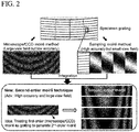
- the aim is to achieve high measurement accuracy of deformation and a wide field of view ( Fig. 2 ) or high accuracy and dynamic measurement at the same time.
- the present invention proposes a 2nd-order moiré method as an innovative deformation measurement technique for achieving a wide field of view and high accuracy or high accuracy and dynamic measurement at the same time.
- a core idea is to treat the recorded or generated traditional moiré fringes as a grating for generating a phase-shifted 2nd-order moiré fringe pattern.
- the phase of the 2nd-order moiré fringes can be calculated more accurately using an algorithm such as the spatial phase shifting method or the spatiotemporal phase shifting method.
- Scanning lines of a microscope, the pixel array of a camera, a virtual grating (down-sampling pixel array), or a digital grating can be used as the reference grating.
- Moiré fringes include microscope moiré fringes, CCD moiré fringes, sampling moiré fringes, and digital moiré fringes.
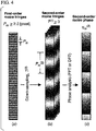
- Fig. 4 shows the principle of a method of generating the first kind of 2nd-order moiré fringes and calculating a phase distribution.
- the pitch of the specimen grating and the pitch of the reference grating (the microscope scanning line or the camera imaging pixel digital grating) in the x-direction (or the y-direction, the direction will be omitted below) are defined as P and T, respectively.
- Equation (1) The intensity distribution of the traditional moiré fringes is expressed by Equation (1) on the assumption that A(x,y) denotes the amplitude of the moiré fringe, ⁇ 0 denotes an initial phase, and B(x,y) includes the background intensity- and high-order frequencies (2 ⁇ x/P, 2 ⁇ x(1/P+1/T), and the like).
- P m (1/P m 1/P-1/T
- the traditional moiré fringes are analyzed by a spatial phase shifting method in the sampling moiré method.
- the traditional moiré fringes are treated as a "grating" used when phase-shifted 2nd-order moiré fringes are generated.
- Equation (3) the intensity of the 2nd-order moiré fringes can be expressed by Equation (3) on the assumption that A (2) (x,y) denotes the amplitude of the 2nd-order moiré fringes, k denotes a number of the phase shifting procedure, and B (2) (x,y) includes the background intensity and high-order frequencies (2 ⁇ x/P, 2 ⁇ x(1/P+1/T), and the like) of the 2nd-order moiré fringes.
- Equation (4) the phase of the 2nd-order moiré fringes is expressed by Equation (4) and can be calculated by one-dimensional discrete Fourier transform (DFT) or fast Fourier transform (FFT).
- DFT discrete Fourier transform
- FFT fast Fourier transform
- a twiddle factor W is defined as in Equation (5).
- the original moiré fringe phase ⁇ m and the original grating phase ⁇ s can be respectively obtained by Equation (6) and Equation (7) using the phase of the 2nd-order moiré fringes which is obtained here.
- ⁇ m x ⁇ m 2 x + 2 ⁇ ⁇ x T 2
- the traditional moiré fringes are regarded as a grating and the sampling moiré method as a spatial phase analysis method is applied, so that it is possible to perform high-accuracy analysis in addition to the original feature of a wide field of view.
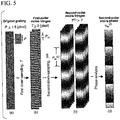
- Fig. 5 shows the principle of the method of calculating the phase distribution of the second kind of 2nd-order moiré fringes.
- a(x,y), b(x,y), and cpo are the amplitude, the background intensity, and the initial phase of the grating, respectively.
- Equation (9) The intensity of the traditional moiré fringes which is obtained by the sampling moiré method can be expressed by Equation (9) on the assumption that A(x,y) denotes the amplitude of the moiré fringes, ⁇ 0 denotes an initial phase, and B(x,y) includes the background intensity and high-order frequencies (2 ⁇ x/P, 2 ⁇ x (1/P+1/T), and the like).
- phase-shifted moiré fringes obtained here are treated as "gratings" used for generation of the 2nd-order moiré fringes.
- T (2) the intensity distribution of the 2nd-order moiré fringes
- a (2) (x,y) denotes the amplitude of the 2nd-order moiré fringes
- k and t denote the numbers of the phase shifting procedures
- B (2) (x,y) denotes the background intensity of the 2nd-order moiré fringes.
- T ⁇ T (2) phase-shifted 2nd-order moiré fringes are obtained.
- Equation (11) the phase of the 2nd-order moiré fringes can be expressed by Equation (11) and calculated by two-dimensional discrete Fourier transform or fast Fourier transform.
- the original moiré fringe phase ⁇ m and the original grating phase ⁇ s can be respectively obtained by Equation (6) and Equation (7) using the phase of the 2nd-order moiré fringes which is obtained here.
- Equation (12) the intensity distribution of the grating image obtained by imaging a one-dimensional grating projected on the surface of the object in an oblique direction or a grating attached to the surface of the specimen by using a digital camera is expressed by Equation (12).
- I x y a x y cos 2 ⁇ x P x + 2 ⁇ y P y + ⁇ 0 + b x y
- P x and P y are pitch intervals of the grating in the x-direction and the y-direction, respectively.
- phase-shifted moiré fringes obtained here are treated as "gratings" used for generation of the 2nd-order moiré fringes.
- Equation (14) When down-sampling pitches in the x-direction and the y-direction are assumed to be T x (2) and T y (2) as down-sampling at the second stage with respect to each of the phase shifting moiré fringes, the intensity distributions of these phase-shifted 2nd-order moiré fringes can be expressed by Equation (14) on the assumption that A (2)(x,y) denotes the amplitude of the 2nd-order moiré fringes, k x and k y denote the numbers of the phase shifting procedures in the x-direction and the y-direction, respectively, and B (2) (x,y) is the background intensity of the 2nd-order moiré fringes. [Math.
- phase of the 2nd-order moiré fringes can be calculated by (multidimensional) discrete Fourier transform or fast Fourier transform as shown in Equation (15). [Math. 15]
- the original moiré fringe phase ⁇ m and the original grating phase ⁇ s can be respectively obtained by Equation (6) and Equation (7) using the phase of the 2nd-order moiré fringes which is obtained here.
- Fig. 6 shows the principle of the method of calculating the phase distribution of the third kind of 2nd-order moiré fringes after adjusting the pitch interval of the traditional moiré fringes
- moiré fringes generated by first down-sampling are regarded as a grating and down-sampling processing is performed again.
- a down-sampling pitch of 2nd-order moiré fringes becomes large, and a spatial resolution may be reduced.
- phase analysis for the 2nd-order moiré fringes can be performed with high accuracy.
- Table 1 shows comparison between features and application conditions of the three techniques according to the present invention which have been described above and traditional phase analysis methods. An optimum method is selectable depending on whether the grating itself to be recorded or the interval between moiré fringes is dense or sparse.
- Table 2 shows comparison between the traditional methods and the present invention in measurement of the three-dimensional shape and the out-of-plane displacement, and Table 3 shows comparison between several traditional methods and the present invention in measurement of the in-plane displacement and strain.
- grating projection and imaging are performed on the reference surface which is a planar object.
- the phase distribution of the reference surface is assumed to be ⁇ ref .
- grating projection and imaging are performed on the object installed in front of the reference surface and the phase distribution of the object is assumed to be ⁇ object .
- the relationship between the phase difference of the reference surface and the object and the height of the object is approximately proportional as shown in Equation. (17).
- phase-to-height conversion factor ⁇ is obtained by calibrating the relation between a distance (height) at each of two locations and the phase difference at that time while moving the reference surface to several locations in advance in the depth (height) direction, it is possible to measure the height of the object in a non-contact manner.
- Equation (21) the 2nd-order moiré fringes after deformation is as shown in Equation (21), similar to Equation (4).
- phase difference between the 2nd-order moiré fringes is equal to the phase difference between the traditional moiré fringes before and after deformation and the phase difference between the specimen gratings before and after deformation.
- the displacement is proportional to the phase difference between the specimen gratings.
- p is the actual pitch of the grating on the specimen surface.
- Equation (23) The displacement of the specimen in the x-direction is determined by Equation (23).
- the strain of the specimen in the x-direction can be measured from the first derivative of the displacement u x .
- ⁇ x ⁇ u x ⁇ x
- Equation (25) measurement of the displacement and strain in the y-direction can be calculated by Equation (25) and Equation (26).
- ⁇ y ⁇ u y ⁇ y
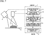
- Fig. 7 is a diagram showing an example of arrangement of a computer 1, an imaging sensor 3, a grating projection device 4, a measurement target 5, and a reference surface (planar object) 6 in a three-dimensional shape measurement system for an object according to the present embodiment.
- the three-dimensional shape measurement system measures the shape of a three-dimensional object as a measurement target.
- a grating pattern which is set from a grating projection control unit 11 (The pitch and the height factor (conversion factors for the phase difference and the height of a regular grating) on a reference surface are known) is projected by the grating projection device 4, and the grating pattern of the projected pattern which is distorted in accordance with the shape of the object is imaged by a fringe grating image storage unit 12 using the imaging sensor 3 (any of various cameras or microscopes).
- the phase distribution of the 2nd-order moiré fringe image is calculated by a 2nd-order moiré fringe generation unit and phase analysis arithmetic operation unit 13 using the method according to the present invention, and the height distribution is further calculated from the phase distribution by a three-dimensional shape arithmetic operation unit 14.
- Measurement results thereof are displayed on a monitor display unit 2.
- Fig. 8 is a diagram showing an example of arrangement of a computer 1, an imaging sensor 3, a structural material 7 as the measurement target, and a minute grating 8 (one-dimensional or two-dimensional) in a displacement and strain distribution measurement system for the material according to the present embodiment.
- the deformation measurement system records the grating image or moiré fringes of a minute grating which is imparted to the surface of the structural material as the measurement target and of which the pitch is known by using the imaging sensor 3.
- the impartation may not only be attachment of a regular grating to the surface of the material but also be a repetitive pattern which exists on the specimen surface in advance, for example, as seen in an atomic array image observed in a metal material.
- Moiré fringes recorded in the storage unit 12 or moiré fringes generated from a grating image are processed by the 2nd-order moiré fringe generation unit and phase analysis arithmetic operation unit 13.
- the displacement and strain distribution results measured by a displacement and strain arithmetic operation unit 15 are further displayed on a monitor 2.
- Fig. 9 is a flowchart showing measurement of the shape and deformation which is performed by the 2nd-order moiré method.
- a regular grating manufactured on the specimen surface, or a periodic structure of the specimen itself can be set to be a grating.
- the image recording device may be a scanning microscope such as a laser scanning microscope (LSM), a scanning electron microscope (SEM), a transmission electron microscope (TEM), or an atomic force microscope (AFM), a digital camera such as a charge coupled device (CCD) camera or a complementary metal oxide semiconductor (CMOS) camera, or a moiré interferometer.
- LSM laser scanning microscope
- SEM scanning electron microscope
- TEM transmission electron microscope
- AFM atomic force microscope
- a digital camera such as a charge coupled device (CCD) camera or a complementary metal oxide semiconductor (CMOS) camera, or a moiré interferometer.
- CCD charge coupled device
- CMOS complementary metal oxide semiconductor
- the scanning line interval of a microscope or the pixel size of a camera is adjusted to the vicinity of the specimen grating pitch (or an integral multiple thereof (a natural number of 2 or greater) or a fractional multiple with an integer as a denominator).
- Microscope or CCD/CMOS moiré fringes are recorded in a wide field of view in the image recording device by interference between the specimen grating and a microscope scanning line or a pixel array.
- interference moiré fringes generated by two coherent laser interferences are recorded by an interferometer.
- Microscope moiré, CCD/CMOS moiré, and interference moiré are techniques for directly observing and recording moiré fringes.
- the specimen grating pitch on a captured image can be reduced to less than two pixels in order to enlarge a field of view.
- Moiré fringes obtained by the sampling moiré method or the digital moiré method are generated by interference between down-sampling and intensity interpolation or between the specimen grating and a digital grating close to the pitch (or an integral multiple or a fractional multiple) of the specimen grating.
- Overlapped (geometric) moiré fringes are generated by overlapping between specimen gratings before and after deformation.
- This shape deformation measurement method is referred to as the 2nd-order moiré method.
- the 2nd-order moiré method can be extended in multiple stages as long as moiré fringes having the same phase difference can be generated using digital gratings.
- the 2nd-order moiré method includes a multistage moiré method to the extent that the method conforms to the problem of the present invention.
- the 2nd-order moiré method may be applied using moiré fringes estimated at the time of obtaining the change in the phase of the moiré fringes and moiré fringes after deformation as moiré fringes before and after deformation.
- this technique is unsuitable in the case in which a distorted grating pattern on a reference surface is imaged because a grating is obliquely projected onto an object in the measurement of the three-dimensional shape described in the first embodiment shown in Fig. 7 , except for the case in which a regular grating image (which would have been obtained in the case of the reference surface) on the reference surface is estimated from the distorted grating image.
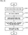
- Fig. 10 is a flowchart showing a shape deformation measurement process according to the present invention.
- the process shown in Fig. 10 includes steps S101, S102, S103, S104, and S105.
- step S105 is performed in a sequential order after step S101.
- a program language can be appropriately selected as long as the above-described equations can be arithmetically operated, and a computer for executing the program may be either a special-purpose machine or a general-purpose machine.
- Effect 1 The proposed technique prominently improves measurement accuracy through phase analysis as compared to the microscope moiré method, the CCD moiré method, the digital moiré method, the overlapped moiré method, and the fringe centering method used for moiré interferometry.
- the strain sensitivity is theoretically 10 -6 .
- Effect 2 An analysis region in the proposed technique can be expanded by several tens to several hundred times as compared to the sampling moiré method, the digital moiré method, and the overlapped moiré method.
- Effect 3 Only a single moiré pattern or a single grating image is required to be recorded for deformation measurement.
- the proposed technique is suitable for a dynamic material test in which the spatiotemporal phase shifting method cannot be applied.
- Effect 4 This technique has good noise-resistance characteristics and can be used for measurement of nanoscale to meter scale non-destructive deformation in the case in which a moiré pattern or a grating image can be recorded.
- Fig. 12(a) shows a repetitive pattern (an alphabetical character A) which exists or is fabricated on the surface of an object.
- Fig. 12(b) shows the moiré fringe image obtained by performing first down-sampling on the pattern shown in Fig. 12(a) at a fixed pitch in the x-direction and the y-direction.
- This moiré fringe image is regarded as a grating, and Fig. 12(c) shows the moiré fringe image obtained by further performing second down-sampling on the moiré fringe image at a fixed pitch in the x-direction and the y-direction.
- the interval between moiré fringes obtained by performing down-sampling processing on a grating image may be large.
- Fig. 13 shows results of generation of (multiplication type) moiré fringes by simulation.
- Fig. 13(a) shows a grating pattern having a pitch interval of 3.02 pixels generated by the simulation.
- Fig. 13(b) shows two phase-shifted moiré fringe images obtained by performing thinning processing on a grating image of Fig. 13(a) with a down-sampling pitch of 2 pixels.
- Fig. 13(c) shows three phase-shifted moiré fringe images obtained by performing thinning processing on the grating image of Fig. 13(a) with a down-sampling pitch of 3 pixels.
- Fig. 13(d) shows four moiré fringe images generated when the number of thinning out for shifting four phases obtained by thinning out the grating image of Fig. 13(a) with a down-sampling pitch of 4 pixels.
- Fig. 13(e) shows a phase distribution image of moiré fringes calculated using the moiré fringe image ( Fig. 13(c) ) generated when the sampling pitch is 3 pixels.
- Fig. 13(f) shows results of the moiré fringe image reconfigured (multiplication type) in the case in which the adjustment factor N is changed from 1 to 20 by using the phase distribution image.
- Verification of non-contact measurement experiment of three-dimensional shape of object which is performed by grating projection method
- Fig. 14 shows an example of analysis results obtained in the case in which the image of a grating, which is projected by a grating projection device, is captured by a camera , and is applied to a 2nd-order moiré method using the three-dimensional shape measurement device as shown in Fig. 7 .
- Fig. 14(a) the grating image captured by projecting sine waves having fixed cycles (cycles of 8 pixels in a projector) on the reference surface is shown in Fig. 14(a) .
- Fig. 14(b) shows a phase distribution of moiré fringes calculated using 25 phase-shifted moiré fringes by applying the traditional sampling moiré method to Fig. 14(a) to perform down-sampling and intensity interpolation on 25 pixels in the horizontal direction.
- Fig. 14(c) shows the phase distribution of 2nd-order moiré fringes calculated by two-dimensional discrete Fourier transform by regarding these moiré fringe images as phase-shifted grating images, further performing down-sampling and intensity interpolation on 100 pixels in the horizontal direction, and using 2500 of 100 ⁇ 25 phase-shifted 2nd-order moiré fringe images to be generated.
- Fig. 14(d) shows the phase distribution of the original projection grating obtained by adding the phase of the sampling point to the phase distribution of 2nd-order moiré fringes (Equation (7)).
- Fig. 15 shows comparison results of analysis performed on the grating image on the reference surface as shown in the Fig. 14(a) according to the phase shifting method, the sampling moiré method, and the spatiotemporal phase shifting method which are traditional techniques and the present invention.
- Fig. 15(a) shows results (phase gradient) obtained by horizontally spatially differentiating a phase distribution obtained by calculating eight captured phase-shifted grating images by the traditional phase shifting method.
- the left diagram shows a phase gradient distribution
- the right diagram is the cross-sectional view of one horizontal center line.
- Fig. 15(b) shows results obtained by calculating one captured grating image by the sampling moiré method (the number of thinning-out is 25 pixels).
- Fig. 15(c) shows results obtained by calculating eight captured phase-shifted grating images by the spatiotemporal phase shifting method (the number of thinning-out is 25 pixels).
- Fig. 15(d) shows results obtained by calculating one captured grating image by the present invention (the number of thinning-out is 25 pixels at the first stage and is 100 pixels at the second stage).
- phase gradient of the reference surface is a smooth straight line with a certain inclination.
- the sampling moiré method can perform phase calculation using one grating image but has a measurement error.
- the spatiotemporal phase shifting method uses both temporal and spatial intensity information, the spatiotemporal phase shifting method is more accurate than the phase shifting method and the sampling moiré method but is not suitable for dynamic measurement because a plurality of images are required.
- Fig. 16 shows analysis results obtained by applying a reference surface and a grating image of an object (hand) obtained by capturing a grating, which is projected by a grating projection device, by a camera to the 2nd-order moiré method using the three-dimensional shape measurement device as shown in Fig. 7 .
- Fig. 16(a) shows images captured by cameras installed at different angles by projecting two types of sinusoidal grating patterns with grating pitch ratios of 8 and 9 on the reference surface and the object in order from the top.
- two types of grating patterns with grating pitch ratios of 8 and 9 are used so that a height can be measured even with an object having a depth.
- phase difference between the reference surface and the object in the case in which the grating pitch ratio is 8 is shown in Fig. 16(c)
- phase difference between the reference surface and the object in the case in which the grating pitch ratio is 9 is shown in Fig. 16(d) .
- the first down-sampling pitch is 29 pixels and the second down-sampling pitch is 110 pixels.
- Fig. 16(e) shows the phase distribution after phase connection of the object (hand) which is obtained by applying the two types of phase difference results shown in Figs. 16(c) and 16(d) to an algorithm of phase connection using the existing grating with a plurality of pitches.
- the height distribution of the object can be finally obtained by multiplying Fig. 16(e) by the height factor obtained by calibration.
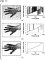
- Fig. 17 shows results of measurement of the height of the hand which are obtained by the traditional phase shifting method and the sampling moiré method and the 2nd-order moiré method according to the present invention.
- Fig. 17(a) shows results of measurement performed by the traditional phase shifting method, and shows data regarding the shape of the hand which is obtained using a total of 17 images of eight images obtained by shifting the phase of the grating image having the grating pitch ratio of 8 by 2 ⁇ /8 and nine images obtained by shifting the phase of the grating image having the grating pitch ratio of 9 by 2 ⁇ /9.
- the left side shows shape distributions, and the right side shows data regarding one horizontal line.
- Fig. 17(b) shows results of measurement performed by the sampling moiré method.
- a dynamic shape can be measured using only a total of two images of an image having the grating pitch ratio of 8 and an image having the grating pitch ratio of 9, but there is a problem in that the measurement results have much noise.
- Fig. 17(c) shows results obtained by the 2nd-order moiré method according to the present invention.
- This example shows analysis results in a condition in which the signal-noise (SN) ratio of the projected grating pattern is extremely low.
- phase shifting method ( Fig. 17(a) ) and the spatiotemporal phase shifting method require a large number of phase-shifted grating images, and thus it is difficult to apply the methods to dynamic measurement.
- the sampling moiré method ( Fig. 17(b) ) is suitable for dynamic measurement.
- measurement results have much noise, and there are many locations where the shape cannot be measured well.
- the present invention is effective for high-accuracy and dynamic three-dimensional shape measurement.
- the present technique using the 2nd-order moiré method uses intensity information in a wide field of view, and thus it is necessary to note that the present technique is not suitable for measurement of a rapidly changing object.
- Example 4 is an example in which accuracy is verified in the case in which the proposed 2nd-order moiré method is performed through simulation and uniform deformation measurement is performed.
- a regular grating having a 10-pixel pitch can be linearly extended and the current strain is 100 ⁇ ( Fig. 18(a) ).
- a grating image of the regular grating was 10,000 pixels long.
- micron strain ( ⁇ ) mentioned here is a minus sixth power of 10 in the unit of the amount of strain.
- the measurement error was only 1 ⁇ , and the accuracy of this measurement method was confirmed.
- the present example is an example indicating that distribution characteristics ( Fig. 19 ) of measurement of the non-uniform displacement and strain are the same as theoretical characteristics.
- a numerical value obtained from MATLAB function peaks (x, y) was added to the phase of a regular grating of 8.1 pixels per pitch (the left side in Fig. 19(a) , before deformation) to deform the regular grating (the right side in Fig. 19(a) , after deformation).
- a grating image was 256 ⁇ 180 pixels.
- An interval between the known moiré fringes before and after deformation was 46 to 57 pixels.
- Phase-shifted 2nd-order moiré fringes before and after deformation were obtained in combination with the spatial phase shifting method by down-sampling the known moiré fringes by 41 pixels ( Fig. 19(c) ).
- the angle of inclination of the grating line was 0.0086 rad
- the grating pitch in the vertical direction was 2.0572 pixels
- the grating image was 1300 ⁇ 900 pixels.
- a random noise with amplitude of 10% of the grating amplitude was added to the inclined grating, and images in the cases in which tensile strains equivalent to 50 ⁇ , 100 ⁇ , 500 ⁇ , 1000 ⁇ , and 2000 ⁇ were loaded were generated through simulation.
- Fig. 21(b) shows the standard deviation of the measured strain.
- a grating having a pitch of 3.0 ⁇ m was manufactured on the surface of the aluminum specimen by UV nanoimprint lithography.
- Fig. 23 shows the deformation measurement process for the aluminum specimen under the tensile load by taking the case in which the value of the strain gauge is 3000 ⁇ as an example.
- Fig. 24 shows stress-strain curves of the aluminum specimen obtained using the mean strain evaluated from the proposed technique and the strain evaluated from the strain gauge.
- the value of the mean strain evaluated from the proposed technique is well matched with that of the strain gauge method, and thus it is possible to verify the validity and measurement accuracy of the proposed technique.
- the proposed 2nd-order moiré method and its program can be used to measure full-field displacements and strains of various materials and structure from nanoscale to meter scale.
- Analyzable objects include metals, polymers, ceramics, semiconductors, composite materials, hybrid structures, and thin films in industrial fields such as aerospace, automobiles, electronic packaging, biomedical fields, military, and material manufacture.
- Typical applications in the industrial field mainly include the following four aspects.
- the proposed technique can predict the region where a crack occurs by finding the strain concentration region from full-field deformation.
- the form of crack propagation can be evaluated by measuring the deformation distribution near the tip of the crack.
- Measurement of the deformation distribution in the vicinity of an interface helps to find areas that are easily destroyed and provides guidance for strengthening and toughening materials and optimal design of materials and interfaces.
- Deformation measurement information can be used to determine material constants such as a stress-strain curve, a Young's modulus, a Poisson's ratio, an elastic limit, a yield strength, and an ultimate strength.
- the proposed technique is useful for industrial fields such as control of manufacturing quality, machine vision, and automatic processing.
Landscapes
- Physics & Mathematics (AREA)
- General Physics & Mathematics (AREA)
- Engineering & Computer Science (AREA)
- Computer Vision & Pattern Recognition (AREA)
- Spectroscopy & Molecular Physics (AREA)
- Life Sciences & Earth Sciences (AREA)
- Health & Medical Sciences (AREA)
- Chemical & Material Sciences (AREA)
- Analytical Chemistry (AREA)
- Biochemistry (AREA)
- General Health & Medical Sciences (AREA)
- Immunology (AREA)
- Pathology (AREA)
- Theoretical Computer Science (AREA)
- Optics & Photonics (AREA)
- Length Measuring Devices By Optical Means (AREA)
Abstract
Description
- An object of the present invention is to develop 2nd-order moiré technology and a program therefor in order to measure a three-dimensional shape, a displacement distribution or a strain distribution of a specimen with high accuracy and a wide field of view. It belongs to the fields of non-destructive measurement, experimental mechanics and optical technology.
- Measurement of the shape and deformation of an object is extremely important for evaluating mechanical properties, structural instability, crack propagation, and residual stress. With miniaturization and integration of products, measurement of deformation at millimeter, micron, and nanoscale levels has attracted much attention in the field of materials science.
- Techniques generally used for measurement of the three-dimensional shape and measurement of minute deformation of an object at present include the digital image correlation (DIC) method, electronic speckle pattern interferometry (ESPI), geometric phase analysis (GPA), the phase analysis methods (for example, Fourier transformation, the phase shifting method, the spatiotemporal phase shifting method, and the like), and the moiré methods, and the like as optical full-field measurement methods.
- Although DIC has high measurement accuracy, it is disadvantageous in that the deformation measurement is easily influenced by the disturbance of noise. ESPI is significantly sensitive to vibration. Since the specimen grating should be directly observed in GPA, the field of view is narrower than that in the scanning moiré method. The Fourier transformation method is another method for analyzing small-scale deformation in a plane, but the field of view is also narrower because the specimen grating to be used should be observed (the width of the field of view is usually less than 100 times the pitch of a grating).
- The moiré methods are effective for performing non-destructive measurement of the deformation distribution from changes in moiré fringes before and after deformation. Among various moiré methods, the microscope moiré method, the CCD or CMOS moiré method (hereinafter, referred to as the CCD moiré method), moiré interferometry, the sampling moiré method, the digital moiré method, and the overlapped (geometric) moiré method have attracted much attention and are applied to deformation measurement of various materials and structures.
- The microscope moiré method and moiré interferometry are suitable for measurement of micron/nanoscale deformation using a microscope. The CCD moiré method, the sampling moiré method, the digital moiré method, and the overlapped moiré method can be used to measure nanoscale to meter scale deformation in the case in which a grating image can be acquired.
- The moiré methods have been applied to measurement of strains of materials such as metals, polymer, and composite materials and deformation of structures such as bridges and buildings. In addition, it is possible to drastically improve measurement accuracy of deformation measurement by analyzing the phase of moiré fringes from a grating image.
- Phase analysis of a fringe grating (fringes or a grating, hereinafter, simply referred to as fringes) image include a phase shifting method for analyzing a phase using a plurality of phase-shifted fringe images as shown in
Fig. 1 , the sampling moiré method for analyzing a phase using only one fringe image, and the spatiotemporal phase shifting method in which a phase shifting method and the sampling moiré method are combined. - In the phase shifting method and the spatiotemporal phase shifting method, it is necessary to capture a plurality of fringe images, and thus the methods cannot be applied to dynamic measurement. The sampling moiré method can analyze a phase from one fringe image and can be applied to dynamic measurement, but there is a problem in that it is impossible to perform high-accuracy measurement in an environment with much noise. A high-accuracy three-dimensional shape and deformation measurement method performed by capturing one fringe image is desired.
-
- [Patent Literature 1]
Japanese Patent No.5818218 - [Patent Literature 2]
PCT International Publication No. WO/2015/008404 : Method and device for measuring displacement distribution using regular pattern, and program for such method and device; Shien Ri and Hiroshi Tsuda - [Patent Literature 3]
Japanese Patent Application No.2016-028169 - [Non-Patent Literature 1]
Qinghua Wang, Hiroshi Tsuda and Huimin Xie, Developments and Applications of Moiré Techniques for Deformation Measurement, Structure Characterization and Shape Analysis, Vol. 8, No. 3, pp. 188-207 (2015) - In the traditional moiré methods including the microscope moiré method, the CCD moiré method, moiré interferometry, the sampling moiré method, the digital moiré method, and the overlapped moiré method, it is difficult to balance the field of view and measurement accuracy.
- In the microscope moiré method, the CCD moiré method, moiré interferometry, the digital moiré method, and the overlapped moiré method, the fringe centering technique is usually adopted for deformation measurement. Since only the center lines of the moiré fringes are used for calculation of the deformation distribution, the measurement accuracy of deformation is not high.
- In the case in which the spatiotemporal phase shifting method disclosed in
Patent Literature 1 is used, it is possible to improve measurement accuracy in the microscope and the CCD moiré method. However, the operation of recording a plurality of phase-shifted moiré fringes and grating images is time consuming and is not suitable for dynamic measurement easily influenced by vibration. - In the sampling moiré method, measurement accuracy can be improved using the spatial phase shifting method, but it is not possible to realize both high accuracy and a wide field of view at the same time. A specimen having a larger grating pitch imparts high measurement accuracy, but has a decreased field of view. A specimen having a smaller grating pitch (less than 3 pixels) can be set to have a wide field of view, but the spatial phase shifting method for calculating deformation cannot be executed.
- The aim is to achieve high measurement accuracy of deformation and a wide field of view (
Fig. 2 ) or high accuracy and dynamic measurement at the same time. - The present invention proposes a 2nd-order moiré method as an innovative deformation measurement technique for achieving a wide field of view and high accuracy or high accuracy and dynamic measurement at the same time.
- A core idea is to treat the recorded or generated traditional moiré fringes as a grating for generating a phase-shifted 2nd-order moiré fringe pattern. The phase of the 2nd-order moiré fringes can be calculated more accurately using an algorithm such as the spatial phase shifting method or the spatiotemporal phase shifting method.
- It is possible to determine the shape and out-of-plane displacement distribution from the phase difference between gratings projected on the surface of a measurement target and a reference surface, or determine the displacement and strain distributions from the phase difference between 2nd-order moiré fringes before and after a grating attached to the surface of an object is deformed.
- As a result, it is possible to measure the three-dimensional shape and out-of-plane displacement distribution, or the in-plane displacement and strain distributions of the object accurately with a wide field of view or dynamically with high accuracy.
- Scanning lines of a microscope, the pixel array of a camera, a virtual grating (down-sampling pixel array), or a digital grating can be used as the reference grating.
- When there is a slight mismatch or misalignment between the specimen grating and the reference grating, traditional moiré fringes will appear from interference between the specimen grating and the reference grating (
Fig. 3(a) ). - Traditional moiré fringes include microscope moiré fringes, CCD moiré fringes, sampling moiré fringes, and digital moiré fringes.
- These traditional moiré fringes are treated as gratings.
- When down-sampling processing is performed with a pitch T(2) close to an interval Pm of the traditional moiré fringes and intensity interpolation is performed on each of down-sampling images by shifting the starting point of down-sampling by one pixel for each of (T(2)-1) times, it is possible to obtain phase-shifted 2nd-order moiré fringes with a T(2) step as shown in
Fig. 3(b) . - There are three methods of generating 2nd-order moiré fringes and three methods of calculating a phase distribution thereof.
-
Fig. 4 shows the principle of a method of generating the first kind of 2nd-order moiré fringes and calculating a phase distribution. - The pitch of the specimen grating and the pitch of the reference grating (the microscope scanning line or the camera imaging pixel digital grating) in the x-direction (or the y-direction, the direction will be omitted below) are defined as P and T, respectively.
- Phase expressions of the specimen grating and the reference grating are ϕs=2πx/P (or (ϕs=2πy/P) and ϕr=2πx/T (or ϕr=2πy/T), respectively.
- The intensity distribution of the traditional moiré fringes is expressed by Equation (1) on the assumption that A(x,y) denotes the amplitude of the moiré fringe, ϕ0 denotes an initial phase, and B(x,y) includes the background intensity- and high-order frequencies (2πx/P, 2πx(1/P+1/T), and the like). Moiré fringes having a pitch interval Pm(1/Pm=1/P-1/T) are generated by a slight difference between the grating pitch P of the specimen and the reference grating or the down-sampling pitch T.
[Math. 1]
- When the high-order frequencies are excluded, the phase of the traditional moiré fringes is expressed by Equation (2).
[Math. 2]
- In order to improve the measurement accuracy of the shape and deformation, the traditional moiré fringes are analyzed by a spatial phase shifting method in the sampling moiré method.
- The traditional moiré fringes are treated as a "grating" used when phase-shifted 2nd-order moiré fringes are generated.
- When a down-sampling pitch is assumed to be T(2), the intensity of the 2nd-order moiré fringes can be expressed by Equation (3) on the assumption that A(2)(x,y) denotes the amplitude of the 2nd-order moiré fringes, k denotes a number of the phase shifting procedure, and B(2)(x,y) includes the background intensity and high-order frequencies (2πx/P, 2πx(1/P+1/T), and the like) of the 2nd-order moiré fringes.
[Math. 3]
- As a result, the phase of the 2nd-order moiré fringes is expressed by Equation (4) and can be calculated by one-dimensional discrete Fourier transform (DFT) or fast Fourier transform (FFT).
[Math. 4]
- Here, a twiddle factor W is defined as in Equation (5).
[Math. 5]
- The original moiré fringe phase ϕm and the original grating phase ϕs can be respectively obtained by Equation (6) and Equation (7) using the phase of the 2nd-order moiré fringes which is obtained here.
[Math. 6]
[Math. 7]
- In this manner, the traditional moiré fringes are regarded as a grating and the sampling moiré method as a spatial phase analysis method is applied, so that it is possible to perform high-accuracy analysis in addition to the original feature of a wide field of view.
-
Fig. 5 shows the principle of the method of calculating the phase distribution of the second kind of 2nd-order moiré fringes. - Here, the pitch of a one-dimensional grating projected on the surface of the object in the vertical direction or a grating attached to the surface of the specimen is assumed to be P. The intensity distribution of the grating image captured in this case is expressed by Equation (8).
[Math. 8]
- Here, a(x,y), b(x,y), and cpo are the amplitude, the background intensity, and the initial phase of the grating, respectively.
- When down-sampling and intensity interpolation are performed on the captured grating image at a sampling (camera imaging pixel digital grating) pitch T in the x-direction, phase expressions of the grating and the sampling grating are ϕs=2πx/P and ϕr=2πx/T, respectively.
- The intensity of the traditional moiré fringes which is obtained by the sampling moiré method can be expressed by Equation (9) on the assumption that A(x,y) denotes the amplitude of the moiré fringes, ϕ0 denotes an initial phase, and B(x,y) includes the background intensity and high-order frequencies (2πx/P, 2πx (1/P+1/T), and the like).
- Unlike Equation (1), a plurality of phase-shifted moiré fringes are obtained here at the same time.
[Math. 9]
- These phase-shifted moiré fringes obtained here are treated as "gratings" used for generation of the 2nd-order moiré fringes. When a down-sampling pitch is assumed to be T(2) as down-sampling at the second stage with respect to each of the phase shifting moiré fringes, the intensity distribution of the 2nd-order moiré fringes can be expressed by Equation (10) on the assumption that A(2)(x,y) denotes the amplitude of the 2nd-order moiré fringes, k and t denote the numbers of the phase shifting procedures, and B(2)(x,y) denotes the background intensity of the 2nd-order moiré fringes.
- In this case, T×T(2) phase-shifted 2nd-order moiré fringes are obtained.
[Math. 10]
- As a result, the phase of the 2nd-order moiré fringes can be expressed by Equation (11) and calculated by two-dimensional discrete Fourier transform or fast Fourier transform.
[Math. 11]
- The original moiré fringe phase ϕm and the original grating phase ϕs can be respectively obtained by Equation (6) and Equation (7) using the phase of the 2nd-order moiré fringes which is obtained here.
- In addition, the intensity distribution of the grating image obtained by imaging a one-dimensional grating projected on the surface of the object in an oblique direction or a grating attached to the surface of the specimen by using a digital camera is expressed by Equation (12).
[Math. 12]
- Here, Px and Py are pitch intervals of the grating in the x-direction and the y-direction, respectively.
- When down-sampling and intensity interpolation are performed on a captured grating image at sampling (camera imaging pixel digital grating) pitches Tx and Ty in the x-direction and the y-direction, respectively, the intensity distribution of the traditional moiré fringes which are obtained by a two-dimensional sampling moiré method can be expressed by Equation (13).
[Math. 13]
- These phase-shifted moiré fringes obtained here are treated as "gratings" used for generation of the 2nd-order moiré fringes.
- When down-sampling pitches in the x-direction and the y-direction are assumed to be Tx (2) and Ty (2) as down-sampling at the second stage with respect to each of the phase shifting moiré fringes, the intensity distributions of these phase-shifted 2nd-order moiré fringes can be expressed by Equation (14) on the assumption that A(2)(x,y) denotes the amplitude of the 2nd-order moiré fringes, kx and ky denote the numbers of the phase shifting procedures in the x-direction and the y-direction, respectively, and B(2)(x,y) is the background intensity of the 2nd-order moiré fringes.
[Math. 14]
- The phase of the 2nd-order moiré fringes can be calculated by (multidimensional) discrete Fourier transform or fast Fourier transform as shown in Equation (15).
[Math. 15]
- The original moiré fringe phase ϕm and the original grating phase ϕs can be respectively obtained by Equation (6) and Equation (7) using the phase of the 2nd-order moiré fringes which is obtained here.
-
Fig. 6 shows the principle of the method of calculating the phase distribution of the third kind of 2nd-order moiré fringes after adjusting the pitch interval of the traditional moiré fringes - In the 2nd-order moiré method according to the present invention, moiré fringes generated by first down-sampling are regarded as a grating and down-sampling processing is performed again. However, in the case in which the pitch interval between the moiré fringes is sparse, a down-sampling pitch of 2nd-order moiré fringes becomes large, and a spatial resolution may be reduced.
- In this case, a method capable of adjusting • the pitch of the moiré fringes using the phase value of the moiré fringes will be described below so that the second down-sampling processing can be performed at an appropriate pitch interval.
- In the sampling moiré method, it is possible to generate dense (multiplied) moiré fringes by performing down-sampling and intensity interpolation processing at a pitch T close to the grating pitch P and using a sine wave or cosine wave function of a value obtained by multiplying a phase value of obtained sparse moiré fringes by N which is an integer shown in Equation (16) again.
[Math. 16]
- When the 2nd-order moiré fringes are generated at a down-sampling pitch of a value close to an interval between adjusted moiré fringes obtained by this method and are applied to the 2nd-order moiré fringe phase calculation method having been described above, phase analysis for the 2nd-order moiré fringes can be performed with high accuracy.
- In this method, it is advantageous to selectively determine whether accuracy is prioritized or a spatial resolution is prioritized by changing N which is an adjustment factor.
- Table 1 shows comparison between features and application conditions of the three techniques according to the present invention which have been described above and traditional phase analysis methods. An optimum method is selectable depending on whether the grating itself to be recorded or the interval between moiré fringes is dense or sparse. Table 2 shows comparison between the traditional methods and the present invention in measurement of the three-dimensional shape and the out-of-plane displacement, and Table 3 shows comparison between several traditional methods and the present invention in measurement of the in-plane displacement and strain.
- As compared with the traditional methods, it is possible to measure the shape and deformation with high accuracy and at high speed or with high accuracy and a wide field of view.
-

-

-

- As an example of the method of measuring an object, for example, grating projection and imaging are performed on the reference surface which is a planar object. The phase distribution of the reference surface is assumed to be ϕref. In addition, grating projection and imaging are performed on the object installed in front of the reference surface and the phase distribution of the object is assumed to be ϕobject. Here, the relationship between the phase difference of the reference surface and the object and the height of the object is approximately proportional as shown in Equation. (17).
[Math. 17]
- Therefore, when the phase-to-height conversion factor κ is obtained by calibrating the relation between a distance (height) at each of two locations and the phase difference at that time while moving the reference surface to several locations in advance in the depth (height) direction, it is possible to measure the height of the object in a non-contact manner.
- When an external force (force, a thermal change, or the like) is loaded to deform a structural material, the pitch of a grating on the surface of the specimen changes from P to P' in the x-direction due to deformation.
- In the case in which the pitch of the reference grating T does not change, the moiré fringe phase after deformation is as shown in Equation (18), similar to Equation (2).
[Math. 18]
- When the pitch of a specimen grating changes from P to P', the phase of the specimen grating of the specimen changes to ϕs=2πy/P', and thus the phase difference between the specimens before and after deformation is as shown in Equation (19).
[Math. 19]
- As seen from Equations (2), (18), and (19), the phase difference between the traditional moiré fringes is equal to the phase difference between the specimen gratings before and after deformation.
[Math. 20]
- With the deformation, in the case in which the pitch of the specimen grating changes from P to P' in the x-direction due to deformation and the pitch of the reference grating T(2) does not change, the 2nd-order moiré fringes after deformation is as shown in Equation (21), similar to Equation (4).
[Math. 21]
- It can be seen that the phase difference between the 2nd-order moiré fringes is equal to the phase difference between the traditional moiré fringes before and after deformation and the phase difference between the specimen gratings before and after deformation.
[Math. 22]
- Assuming that u expresses the displacement of the specimen grating in the x-direction, the phase of the deformed specimen grating can be expressed as ϕs'(x)=2π(x-u)/P.
- The phase difference between the specimen gratings can be calculated by Δϕs(x)=ϕs'(x)-ϕs(x)=-2πu/p on the basis of the phase ϕs(x)=2πx/p of the specimen grating before deformation. As a result, the displacement is proportional to the phase difference between the specimen gratings.
- Here, p is the actual pitch of the grating on the specimen surface.
- The displacement of the specimen in the x-direction is determined by Equation (23).
[Math. 23]
- The strain of the specimen in the x-direction can be measured from the first derivative of the displacement ux.
[Math. 24]
- Similarly, in the case in which the pitch of the grating in the y-direction is p, measurement of the displacement and strain in the y-direction can be calculated by Equation (25) and Equation (26).
[Math. 25]
[Math. 26]
- Hereinafter, the first embodiment of the present invention will be described with reference to the accompanying drawings.
-
Fig. 7 is a diagram showing an example of arrangement of acomputer 1, animaging sensor 3, agrating projection device 4, ameasurement target 5, and a reference surface (planar object) 6 in a three-dimensional shape measurement system for an object according to the present embodiment. - In the example shown in
Fig. 7 , the three-dimensional shape measurement system measures the shape of a three-dimensional object as a measurement target. - A grating pattern which is set from a grating projection control unit 11 (The pitch and the height factor (conversion factors for the phase difference and the height of a regular grating) on a reference surface are known) is projected by the
grating projection device 4, and the grating pattern of the projected pattern which is distorted in accordance with the shape of the object is imaged by a fringe gratingimage storage unit 12 using the imaging sensor 3 (any of various cameras or microscopes). - With respect to the captured image, the phase distribution of the 2nd-order moiré fringe image is calculated by a 2nd-order moiré fringe generation unit and phase analysis
arithmetic operation unit 13 using the method according to the present invention, and the height distribution is further calculated from the phase distribution by a three-dimensional shape arithmetic operation unit 14. - Measurement results thereof are displayed on a
monitor display unit 2. -
Fig. 8 is a diagram showing an example of arrangement of acomputer 1, animaging sensor 3, astructural material 7 as the measurement target, and a minute grating 8 (one-dimensional or two-dimensional) in a displacement and strain distribution measurement system for the material according to the present embodiment. - In the example shown in
Fig. 8 , the deformation measurement system records the grating image or moiré fringes of a minute grating which is imparted to the surface of the structural material as the measurement target and of which the pitch is known by using theimaging sensor 3. - The impartation may not only be attachment of a regular grating to the surface of the material but also be a repetitive pattern which exists on the specimen surface in advance, for example, as seen in an atomic array image observed in a metal material.
- Moiré fringes recorded in the
storage unit 12 or moiré fringes generated from a grating image are processed by the 2nd-order moiré fringe generation unit and phase analysisarithmetic operation unit 13. The displacement and strain distribution results measured by a displacement and strainarithmetic operation unit 15 are further displayed on amonitor 2. -
Fig. 9 is a flowchart showing measurement of the shape and deformation which is performed by the 2nd-order moiré method. - (S1) In the case of measurement of the three-dimensional shape, a grating pattern is projected on the surface of the object.
- In the case of measurement of displacement and strain distributions, a regular grating manufactured on the specimen surface, or a periodic structure of the specimen itself can be set to be a grating.
- (S2) Next, the specimen grating is disposed under an image recording device.
- The image recording device may be a scanning microscope such as a laser scanning microscope (LSM), a scanning electron microscope (SEM), a transmission electron microscope (TEM), or an atomic force microscope (AFM), a digital camera such as a charge coupled device (CCD) camera or a complementary metal oxide semiconductor (CMOS) camera, or a moiré interferometer.
- Next, the scanning line interval of a microscope or the pixel size of a camera is adjusted to the vicinity of the specimen grating pitch (or an integral multiple thereof (a natural number of 2 or greater) or a fractional multiple with an integer as a denominator).
- Microscope or CCD/CMOS moiré fringes are recorded in a wide field of view in the image recording device by interference between the specimen grating and a microscope scanning line or a pixel array.
- Alternatively, interference moiré fringes generated by two coherent laser interferences are recorded by an interferometer.
- Microscope moiré, CCD/CMOS moiré, and interference moiré are techniques for directly observing and recording moiré fringes.
- In addition to this, there are methods of capturing a grating image and generating moiré fringes (for example, digital moiré, sampling moiré, overlapped moiré, and the like) by image processing.
- In these techniques, the specimen grating pitch on a captured image can be reduced to less than two pixels in order to enlarge a field of view.
- Moiré fringes obtained by the sampling moiré method or the digital moiré method are generated by interference between down-sampling and intensity interpolation or between the specimen grating and a digital grating close to the pitch (or an integral multiple or a fractional multiple) of the specimen grating. Overlapped (geometric) moiré fringes are generated by overlapping between specimen gratings before and after deformation.
- (S3) Phase-shifted 2nd-order moiré fringes are generated by down sampling, intensity interpolation, and spatial phase shifting by using these traditional moiré fringes and a pitch close to the interval therebetween.
- Then, it is possible to obtain the phase distribution of 2nd-order moiré fringes from the phase-shifted 2nd-order moiré fringes.
- (S5) It is possible to accurately perform quantitative evaluation of (S4) displacement and strain distributions with a wide field of view from the phase difference between 2nd-order moiré fringes before and after deformation.
- This shape deformation measurement method is referred to as the 2nd-order moiré method.
- The 2nd-order moiré method can be extended in multiple stages as long as moiré fringes having the same phase difference can be generated using digital gratings.
- Accordingly, the 2nd-order moiré method includes a multistage moiré method to the extent that the method conforms to the problem of the present invention.
- In the case in which moiré fringes before deformation can be estimated by comparing the change in the phase (phase gradient) of moiré fringes of an undeformed portion and the change in the phase of moiré fringes of a deformed portion with each other from only one moiré fringe pattern after deformation, it is also possible to obtain the strain from one moiré fringe pattern after deformation.
- The 2nd-order moiré method may be applied using moiré fringes estimated at the time of obtaining the change in the phase of the moiré fringes and moiré fringes after deformation as moiré fringes before and after deformation.
- However, this technique is unsuitable in the case in which a distorted grating pattern on a reference surface is imaged because a grating is obliquely projected onto an object in the measurement of the three-dimensional shape described in the first embodiment shown in
Fig. 7 , except for the case in which a regular grating image (which would have been obtained in the case of the reference surface) on the reference surface is estimated from the distorted grating image. - Next, the shape deformation measurement process according to the present invention will be described.
Fig. 10 is a flowchart showing a shape deformation measurement process according to the present invention. The process shown inFig. 10 includes steps S101, S102, S103, S104, and S105. - In the process shown in
Fig. 10 , the processing of step S105 is performed in a sequential order after step S101. - A program language can be appropriately selected as long as the above-described equations can be arithmetically operated, and a computer for executing the program may be either a special-purpose machine or a general-purpose machine.
- After the grating pattern or moiré fringes are recorded (S101), parameters such as pitch dimesions, the height factor, and an integer for generating moiré fringes are input (S102), a necessary arithmetic operation is performed using the 2nd-order moiré method (S103), the amounts of the shape, displacement, or strain is calculated from a phase component of 2nd-order moiré fringes (S104), and results thereof are displayed (S105).
- According to the present invention, it is possible to measure the full- field displacement and strain distributions with a wide field of view and a high level of measurement accuracy or dynamically with high accuracy by the 2nd-order moiré method, and thus the following effects are exerted (
Fig. 11 ). - Effect 1: The proposed technique prominently improves measurement accuracy through phase analysis as compared to the microscope moiré method, the CCD moiré method, the digital moiré method, the overlapped moiré method, and the fringe centering method used for moiré interferometry. The strain sensitivity is theoretically 10-6. In addition, according to the present invention, it is possible to eliminate strain measurement errors caused by scanning distortion of various microscopes.
- Effect 2: An analysis region in the proposed technique can be expanded by several tens to several hundred times as compared to the sampling moiré method, the digital moiré method, and the overlapped moiré method.
- Effect 3: Only a single moiré pattern or a single grating image is required to be recorded for deformation measurement.
- The proposed technique is suitable for a dynamic material test in which the spatiotemporal phase shifting method cannot be applied.
- Effect 4: This technique has good noise-resistance characteristics and can be used for measurement of nanoscale to meter scale non-destructive deformation in the case in which a moiré pattern or a grating image can be recorded.
-
-
Fig. 1 is a diagram showing principles of different phase analysis techniques. -
Fig. 2 shows fields of view in different moiré methods. -
Fig. 3(a) is a diagram showing traditional moiré fringes, andFig. 3(b) is a diagram showing the principle of formation of the 2nd-order moiré fringes. -
Fig. 4 is a diagram showing the principle of calculation of the phase distribution of the obtained 2nd-order moiré fringes by performing down-sampling processing on a moiré fringe pattern. -
Fig. 5 is a diagram showing the principle of calculation of the phase distribution of the obtained 2nd-order moiré fringes by performing down-sampling processing on a grating image in two stages. -
Fig. 6 is a flow diagram showing the principle of generation of multiplication type moiré fringes using a phase distribution and imaging processing. -
Fig. 7 is a configuration diagram of the three-dimensional shape measurement device according to the present invention. -
Fig. 8 is a configuration diagram of a displacement and strain measurement device according to the present invention. -
Fig. 9 is a flowchart of the deformation measurement step in the proposed technique. -
Fig. 10 is a flowchart of the deformation measurement program in the proposed technique. -
Fig. 11 is a table showing comparison between distributions of strain measurement accuracies of different moiré methods. -
Fig. 12 shows an example in which the 2nd-order moiré method is applied to any two-dimensional repetitive patterns. -
Fig. 13 shows an example in which multiplication type moiré fringes are generated by the third method according to the present invention. -
Fig. 14 shows an example of phase analysis performed on a projection grating by the 2nd-order moiré method. -
Fig. 15 is a diagram showing comparison between phase analysis results of projection gratings according to the traditional methods and the present invention. -
Fig. 16 shows an example in which the 2nd-order moiré method is applied to the measurement of the three-dimensional non-contact shape through grating projection. -
Fig. 17 is a diagram showing comparison between height measurement results of objects according to the traditional methods and the present invention. -
Fig. 18 is a diagram showing simulation verification results of uniform deformation measurement in the proposed technique. -
Fig. 19 is a diagram showing simulation verification results of non-uniform deformation measurement in the proposed technique. -
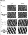
Fig. 20 is a diagram showing analysis results of displacement and strain distributions obtained using inclined gratings having random noise in the case in which strain values obtained by simulation are 0 µε and 1000 µε. -
Fig. 21(a) is diagram showing the error of the mean strain measured by the 2nd-order moiré method on the basis of the strain value (preset) obtained by simulation, andFig. 21(b) is diagram showing the standard deviation of the measured strain. -
Fig. 22 is photographs showing an aluminum test piece and setup of a tension experiment using a laser microscope. -
Fig. 23 is a diagram showing results of displacement and strain distribution measurement performed by the 2nd-order moiré method when the strain gauge value is 3000 µε during the tension test for the aluminum test piece. -
Fig. 24 is a diagram showing comparison between the stress curve and the strain curve of the aluminum specimen which are obtained using the proposed technique and a strain gauge. - Here, effects in the case in which a 2nd-order moiré method is applied to any two-dimensional repetitive pattern are described.
-
Fig. 12(a) shows a repetitive pattern (an alphabetical character A) which exists or is fabricated on the surface of an object. -
Fig. 12(b) shows the moiré fringe image obtained by performing first down-sampling on the pattern shown inFig. 12(a) at a fixed pitch in the x-direction and the y-direction. - This moiré fringe image is regarded as a grating, and
Fig. 12(c) shows the moiré fringe image obtained by further performing second down-sampling on the moiré fringe image at a fixed pitch in the x-direction and the y-direction. - It can be understood that the original repetitive pattern A is further enlarged.
- This is called 2nd-order moiré.
- In the present invention, the interval between moiré fringes obtained by performing down-sampling processing on a grating image may be large.
- In this case, it is possible to reconfigure multiplication type moiré fringes in which the interval between moiré fringes becomes small so that an appropriate interval between moiré fringes is obtained by the third method according to the present invention.
-
Fig. 13 shows results of generation of (multiplication type) moiré fringes by simulation. -
Fig. 13(a) shows a grating pattern having a pitch interval of 3.02 pixels generated by the simulation. -
Fig. 13(b) shows two phase-shifted moiré fringe images obtained by performing thinning processing on a grating image ofFig. 13(a) with a down-sampling pitch of 2 pixels. - Since the grating pitch P (3.02 pixels) is greatly different from the sampling pitch T (2 pixels), it can be confirmed that moiré fringes cannot be generated.
-
Fig. 13(c) shows three phase-shifted moiré fringe images obtained by performing thinning processing on the grating image ofFig. 13(a) with a down-sampling pitch of 3 pixels. - Since the grating pitch P (3.02 pixels) and the sampling pitch T (3 pixels) are close to each other, distinct moiré fringes can be generated, but it can be understood that the interval between the moiré fringes is large.
- The application of the 2nd-order moiré method in this situation results in a problem in that the spatial resolution is significantly decreased.
-
Fig. 13(d) shows four moiré fringe images generated when the number of thinning out for shifting four phases obtained by thinning out the grating image ofFig. 13(a) with a down-sampling pitch of 4 pixels. - Similarly to
Fig. 13(b) , since the grating pitch P (3.02 pixels) and a sampling pitch T (4 pixels) are greatly different from each other, it can be understood that moiré fringes cannot be generated. -
Fig. 13(e) shows a phase distribution image of moiré fringes calculated using the moiré fringe image (Fig. 13(c) ) generated when the sampling pitch is 3 pixels. -
Fig. 13(f) shows results of the moiré fringe image reconfigured (multiplication type) in the case in which the adjustment factor N is changed from 1 to 20 by using the phase distribution image. - In this manner, it is possible to adjust the interval between moiré fringes from a sparse state to a dense state by changing the adjustment factor N.
- Effects of the improvement in the accuracy of non-contact measurement of the three-dimensional shape of an object which is performed by the 2nd-order moiré method proposed in the present invention are confirmed through an experiment.
-
Fig. 14 shows an example of analysis results obtained in the case in which the image of a grating, which is projected by a grating projection device, is captured by a camera , and is applied to a 2nd-order moiré method using the three-dimensional shape measurement device as shown inFig. 7 . - Here, the grating image captured by projecting sine waves having fixed cycles (cycles of 8 pixels in a projector) on the reference surface is shown in
Fig. 14(a) . -
Fig. 14(b) shows a phase distribution of moiré fringes calculated using 25 phase-shifted moiré fringes by applying the traditional sampling moiré method toFig. 14(a) to perform down-sampling and intensity interpolation on 25 pixels in the horizontal direction. -
Fig. 14(c) shows the phase distribution of 2nd-order moiré fringes calculated by two-dimensional discrete Fourier transform by regarding these moiré fringe images as phase-shifted grating images, further performing down-sampling and intensity interpolation on 100 pixels in the horizontal direction, and using 2500 of 100×25 phase-shifted 2nd-order moiré fringe images to be generated. -
Fig. 14(d) shows the phase distribution of the original projection grating obtained by adding the phase of the sampling point to the phase distribution of 2nd-order moiré fringes (Equation (7)). - In the case of this example, it is possible to generate 2500 phase-shifted moiré fringes from one grating image and to perform phase analysis with a higher level of accuracy.
-
Fig. 15 shows comparison results of analysis performed on the grating image on the reference surface as shown in theFig. 14(a) according to the phase shifting method, the sampling moiré method, and the spatiotemporal phase shifting method which are traditional techniques and the present invention. -
Fig. 15(a) shows results (phase gradient) obtained by horizontally spatially differentiating a phase distribution obtained by calculating eight captured phase-shifted grating images by the traditional phase shifting method. - The left diagram shows a phase gradient distribution, and the right diagram is the cross-sectional view of one horizontal center line.
- Similarly,
Fig. 15(b) shows results obtained by calculating one captured grating image by the sampling moiré method (the number of thinning-out is 25 pixels). -
Fig. 15(c) shows results obtained by calculating eight captured phase-shifted grating images by the spatiotemporal phase shifting method (the number of thinning-out is 25 pixels). -
Fig. 15(d) shows results obtained by calculating one captured grating image by the present invention (the number of thinning-out is 25 pixels at the first stage and is 100 pixels at the second stage). - A correct result is that the phase gradient of the reference surface is a smooth straight line with a certain inclination.
- As can be seen from the results of
Fig. 15 , the traditional phase shifting methods have great measurement errors. - The sampling moiré method can perform phase calculation using one grating image but has a measurement error.
- Since the spatiotemporal phase shifting method uses both temporal and spatial intensity information, the spatiotemporal phase shifting method is more accurate than the phase shifting method and the sampling moiré method but is not suitable for dynamic measurement because a plurality of images are required.
- On the other hand, according to the present invention, the most accurate results are obtained using only one grating image, and thus the effectiveness of the present invention is shown.
- Next, an example in which the dynamic three-dimensional shape is measured with high accuracy by the second method according to the present invention will be described.
-
Fig. 16 shows analysis results obtained by applying a reference surface and a grating image of an object (hand) obtained by capturing a grating, which is projected by a grating projection device, by a camera to the 2nd-order moiré method using the three-dimensional shape measurement device as shown inFig. 7 . -
Fig. 16(a) shows images captured by cameras installed at different angles by projecting two types of sinusoidal grating patterns with grating pitch ratios of 8 and 9 on the reference surface and the object in order from the top. - Phase distributions calculated by performing the 2nd-order moiré method on these images are shown in
Fig. 16(b) . - Here, two types of grating patterns with grating pitch ratios of 8 and 9 are used so that a height can be measured even with an object having a depth.
- The phase difference between the reference surface and the object in the case in which the grating pitch ratio is 8 is shown in
Fig. 16(c) , and similarly, the phase difference between the reference surface and the object in the case in which the grating pitch ratio is 9 is shown inFig. 16(d) . - Analysis conditions in the case in which the grating pitch ratio is 8 are the same as those in
Fig. 14 . - In analysis conditions in the case in which the grating pitch ratio is 9, the first down-sampling pitch is 29 pixels and the second down-sampling pitch is 110 pixels.
-
Fig. 16(e) shows the phase distribution after phase connection of the object (hand) which is obtained by applying the two types of phase difference results shown inFigs. 16(c) and 16(d) to an algorithm of phase connection using the existing grating with a plurality of pitches. - The height distribution of the object can be finally obtained by multiplying
Fig. 16(e) by the height factor obtained by calibration. -
Fig. 17 shows results of measurement of the height of the hand which are obtained by the traditional phase shifting method and the sampling moiré method and the 2nd-order moiré method according to the present invention. -
Fig. 17(a) shows results of measurement performed by the traditional phase shifting method, and shows data regarding the shape of the hand which is obtained using a total of 17 images of eight images obtained by shifting the phase of the grating image having the grating pitch ratio of 8 by 2 π/8 and nine images obtained by shifting the phase of the grating image having the grating pitch ratio of 9 by 2π/9. - The left side shows shape distributions, and the right side shows data regarding one horizontal line.
-
Fig. 17(b) shows results of measurement performed by the sampling moiré method. A dynamic shape can be measured using only a total of two images of an image having the grating pitch ratio of 8 and an image having the grating pitch ratio of 9, but there is a problem in that the measurement results have much noise. -
Fig. 17(c) shows results obtained by the 2nd-order moiré method according to the present invention. - This example shows analysis results in a condition in which the signal-noise (SN) ratio of the projected grating pattern is extremely low.
- Therefore, the phase shifting method (
Fig. 17(a) ) and the spatiotemporal phase shifting method require a large number of phase-shifted grating images, and thus it is difficult to apply the methods to dynamic measurement. - On the other hand, the sampling moiré method (
Fig. 17(b) ) is suitable for dynamic measurement. However, measurement results have much noise, and there are many locations where the shape cannot be measured well. - According to the present invention (
Fig. 17(c) ), it can be confirmed that it is possible to calculate the shape of the hand with less measurement errors using only a total of two images of an image having the grating pitch ratio of 8 and an image having the grating pitch ratio of 9. - As can be seen from the experiment results of
Fig. 17 , the present invention is effective for high-accuracy and dynamic three-dimensional shape measurement. - However, the present technique using the 2nd-order moiré method uses intensity information in a wide field of view, and thus it is necessary to note that the present technique is not suitable for measurement of a rapidly changing object.
- Example 4 is an example in which accuracy is verified in the case in which the proposed 2nd-order moiré method is performed through simulation and uniform deformation measurement is performed.
- A regular grating having a 10-pixel pitch can be linearly extended and the current strain is 100 µε (
Fig. 18(a) ). A grating image of the regular grating was 10,000 pixels long. - The micron strain (µε) mentioned here is a minus sixth power of 10 in the unit of the amount of strain.
- When the pitch of the reference grating was 9 pixels, well-known digital sampling moiré fringes before and after deformation were obtained (
Fig. 18(b) ). - Both intervals between the well-known moiré fringes before and after deformation were approximately 90 pixels.
- Known moiré fringes were treated as regular gratings and down-sampled by 88 pixels, and 2nd-order moiré fringes before and after deformation were obtained in combination with the spatial phase shifting method (
Fig. 18(c) ). - The phase of the 2nd-order moiré fringes before and after deformation was calculated using the present invention (
Fig. 18(d) ). - Next, changes in phase and displacements having the same distribution characteristics were measured (
Fig. 18(e) ). - Finally, the strain distribution was determined, so that the mean strain of 101 µε was obtained.
- As compared with the
preset strain 100 µε, the measurement error was only 1 µε, and the accuracy of this measurement method was confirmed. - The present example is an example indicating that distribution characteristics (
Fig. 19 ) of measurement of the non-uniform displacement and strain are the same as theoretical characteristics. - A numerical value obtained from MATLAB function peaks (x, y) was added to the phase of a regular grating of 8.1 pixels per pitch (the left side in
Fig. 19(a) , before deformation) to deform the regular grating (the right side inFig. 19(a) , after deformation). - A grating image was 256×180 pixels.
- When the reference grating pitch was set to 7 pixels, known moiré fringes before and after deformation appeared (
Fig. 19(b) ). - An interval between the known moiré fringes before and after deformation was 46 to 57 pixels.
- Phase-shifted 2nd-order moiré fringes before and after deformation were obtained in combination with the spatial phase shifting method by down-sampling the known moiré fringes by 41 pixels (
Fig. 19(c) ). - The phase of the moiré fringes before and after deformation was obtained using the present invention (
Fig. 19(d) ). - Changes in the phases (
Fig. 19(e) ) and displacement and strain distributions were measured. - Distribution characteristics of the measured displacement and strain (
Fig. 19(f) ) matched theoretically obtained results. - In the present example, measurement of the displacement of an inclined grating with random noise will be described.
- The angle of inclination of the grating line was 0.0086 rad, the grating pitch in the vertical direction was 2.0572 pixels, and the grating image was 1300×900 pixels.
- A random noise with amplitude of 10% of the grating amplitude was added to the inclined grating, and images in the cases in which tensile strains equivalent to 50 µε, 100 µε, 500 µε, 1000 µε, and 2000 µε were loaded were generated through simulation.
- The process of generating moiré fringes and 2nd-order moiré fringes in the cases in which strains are 0 µε and 1000 µε is shown in
Fig. 20 . It is possible to measure displacement and strain from the phase difference between 2nd-order moiré fringes. - Errors of the mean strain measured by setting strains given through simulation to the horizontal axis are shown in
Fig. 21(a) . -
Fig. 21(b) shows the standard deviation of the measured strain. - Since all of relative errors are less than 1% and standard deviations are less than 4×10⁻⁵, it can be confirmed that high-accuracy strain measurement can be performed.
- In the present example, validity and accuracy of the proposed deformation measurement are shown through experiment.
- An aluminum specimen was stretched under a laser microscope (
Fig. 22 ). - Dimensions of the aluminum specimen were 27, 6.3, and 0.5 (mm) in length, width, and thickness, respectively.
- A grating having a pitch of 3.0 µm was manufactured on the surface of the aluminum specimen by UV nanoimprint lithography.
- After a strain gauge is attached to the side opposite to the specimen, a tensile load was applied under the microscope.
- Laser scanning moiré fringes generated due to interference between the grating on the specimen and the scanning line was observed by making the magnification of the objective lens as 5 times.
- A series of laser scanning moiré fringes were recorded during the tension process.
-
Fig. 23 shows the deformation measurement process for the aluminum specimen under the tensile load by taking the case in which the value of the strain gauge is 3000 µε as an example. -
Fig. 24 shows stress-strain curves of the aluminum specimen obtained using the mean strain evaluated from the proposed technique and the strain evaluated from the strain gauge. - The value of the mean strain evaluated from the proposed technique is well matched with that of the strain gauge method, and thus it is possible to verify the validity and measurement accuracy of the proposed technique.
- The proposed 2nd-order moiré method and its program can be used to measure full-field displacements and strains of various materials and structure from nanoscale to meter scale.
- Analyzable objects include metals, polymers, ceramics, semiconductors, composite materials, hybrid structures, and thin films in industrial fields such as aerospace, automobiles, electronic packaging, biomedical fields, military, and material manufacture.
- Typical applications in the industrial field mainly include the following four aspects.
- The proposed technique can predict the region where a crack occurs by finding the strain concentration region from full-field deformation.
- The form of crack propagation can be evaluated by measuring the deformation distribution near the tip of the crack.
- It is possible to quantitatively analyze modes of damages including an instability mode, layer separation, buckling, and a crack due to various mechanical loads, electric loads, thermal loads, magnetic loads, and combined loads thereof.
- It is possible to detect the residual strain inside a material and the influence on its structural stability in combination with a stress release method (heating, a hole drilling method, a ring core method, or the like).
- Measurement of the deformation distribution in the vicinity of an interface helps to find areas that are easily destroyed and provides guidance for strengthening and toughening materials and optimal design of materials and interfaces.
- Deformation measurement information can be used to determine material constants such as a stress-strain curve, a Young's modulus, a Poisson's ratio, an elastic limit, a yield strength, and an ultimate strength.
- It is possible to evaluate displacement and strain distributions caused by a mechanical, electrical, or thermal load for structural health monitoring.
- It is possible to quantitatively evaluate the height, depth, surface flatness, and the out-of-plane displacement of an object from the measured three-dimensional shape. The proposed technique is useful for industrial fields such as control of manufacturing quality, machine vision, and automatic processing.
-
- 1 Computer
- 2 Monitor
- 3 Imaging sensor (various cameras and microscopes)
- 4 Grating projection device
- 5 Three-dimensional object as measurement target
- 6 Reference surface (planar object)
- 7 Structural material as measurement target
- 8 Minute grating (one-dimensional or two-dimensional)
- 11 Grating projection control unit
- 12 Fringe grating image storage unit
- 13 2nd-order moiré fringe generation unit and phase analysis arithmetic operation unit
- 14 Three-dimensional shape arithmetic operation unit
- 15 Displacement and strain arithmetic operation unit
Claims (7)
- A method for measuring a three-dimensional shape, a displacement distribution, or a strain distribution using 2nd-order moiré fringes (image information captured in a group of pixels regularly arranged and capable of having intensity information) to measure a shape of a surface of a specimen or an in-plane displacement, an out-of-plane displacement, and a strain with high accuracy and a wide field of view, comprising:obtaining 2nd-order moiré fringes on a reference surface and the specimen surface or before and after deformation (hereinafter, simply referred to as "before and after deformation"), by performing down-sampling and intensity interpolation processing at a pitch close to an interval between the moiré fringes, or a pitch which is an integral multiple (a natural number of 2 or greater, the same applies hereinafter) or a fractional multiple with an integer as a denominator using the moiré fringes generated from a regular grating, of which a height factor (conversion factors of a phase and height of the regular grating) is known; andfurther determining the three-dimensional shape and out-of-plane displacement of the specimen using the height factor, or the in-plane displacement and strain distributions using the grating pitch, from a difference between phase distributions of the 2nd-order moiré fringes before and after deformation obtained by a spatial phase shifting method from the 2nd-order moiré fringes before and after deformation.
- The method for measuring the three-dimensional shape, the displacement distribution, or the strain distribution using 2nd-order moiré fringes according to claim 1,
wherein moiré fringes obtained with respect to the shape of the surface and the reference surface of the specimen, or the specimen before and after deformation are shadow moiré fringes, projection moiré fringes, microscope moiré fringes, CCD/CMOS moiré fringes, interference moiré fringes, digital moiré fringes, sampling moiré fringes, and overlapped moiré fringes which are obtained by a grating projection device (a liquid crystal projector, a DLP projector, an LCoS projector, and a Ronchi grating projection are included), an image recording device (a digital camera, an LSM, an SEM, a TEM, and an AFM microscope are included), a laser interferometer, a computer, and a mobile terminal (hereinafter, referred to as an image recording device and the like). - A method for measuring a three-dimensional shape, a displacement distribution, or a strain distribution using 2nd-order moiré fringes to measure the three-dimensional shape, an in-plane displacement, an out-of-plane displacement, and a strain of a specimen with high accuracy and a wide field of view by analyzing an image of a regular grating which exists or is projected, drawn, manufactured, or attached on the specimen,
wherein images of regular gratings on a reference surface and the specimen surface or before and after deformation (hereinafter, simply referred to as "before and after deformation") are recorded by an image recording device and the like,
the height factor is further calculated in the three-dimensional shape,
an image of digital moiré fringes, sampling moiré fringes, or overlapped moiré fringes before and after deformation of the specimen is generated from each recorded image of the regular grating before and after deformation,
2nd-order moiré fringes before and after deformation are obtained by performing down-sampling and intensity interpolation processing at a pitch close to an interval between the moiré fringes, or a pitch which is an integral multiple (a natural number of 2 or greater, the same applies hereinafter) or a fractional multiple with an integer as a denominator using each image of digital moiré fringes, sampling moiré fringes, or overlapped moiré fringes before and after deformation of the specimen, and
the three-dimensional shape and the out-of-plane displacement distribution of the specimen are further determined using the height factor, or the in-plane displacement and strain distributions of the specimen are further determined using the grating pitch, from a difference between phase distributions of the 2nd-order moiré fringes before and after deformation obtained by a spatial phase shifting method from the 2nd-order moiré fringes before and after deformation. - A method for measuring a three-dimensional shape, a displacement distribution, or a strain distribution using 2nd-order moiré fringes to measure the three-dimensional shape, an out-of-plane displacement distribution, an in-plane displacement distribution, or strain distribution with high accuracy and a wide field of view by analyzing an image of a regular grating which exists or is projected, drawn, manufactured, or attached on the specimen,
wherein images of regular gratings on a reference surface and the specimen surface or before and after deformation (hereinafter, simply referred to as "before and after deformation") are recorded by an image recording device and the like,
n spatial phase-shifted digital moiré fringes or sampling moiré fringes (n is a natural number of 2 or greater) are generated with respect to the specimen before and after deformation from each recorded image of the regular grating before and after deformation,
each n groups of 2nd-order moiré fringes before and after deformation are obtained by performing down-sampling and intensity interpolation processing at a pitch close to an interval between the moiré fringes, or a pitch which is an integral multiple (a natural number of 2 or greater, the same applies hereinafter) or a fractional multiple with an integer as a denominator using the n spatial phase-shifted digital moiré fringes or sampling moiré fringes (n is a natural number of 2 or greater) of the specimen before and after deformation, and
the three-dimensional shape and the out-of-plane displacement distribution of the specimen are further determined using the height factor, or the in-plane displacement and strain distributions of the specimen are further determined using the grating pitch, from a difference between mean values of phase distributions of each n groups of the 2nd-order moiré fringes before and after deformation of the n groups which are obtained from the 2nd-order moiré fringes before and after deformation of the n groups by a spatial phase shifting method. - A method for measuring a three-dimensional shape, a displacement distribution, and a strain distribution using 2nd-order moiré fringes comprising:in a case in which the image of digital moiré fringes, sampling moiré fringes, or overlapped moiré fringes before and after deformation of the specimen according to claim 1, the image of digital moiré fringes, sampling moiré fringes, or overlapped moiré fringes before and after deformation of the specimen according to claim 3, or the n images of the spatial phase-shifted digital moiré fringes or sampling moiré fringes (n is a natural number of 2 or greater) before and after deformation of the specimen according to claim 4 are sparse moiré fringes,obtaining each phase distribution of the moiré fringes before and after deformation of the specimen by a spatial phase shifting method;reconstructing multiplication moiré fringes having dense moiré fringes through inverse Fourier transformation by making phase values of the moiré fringes N times (N is a natural number of 2 or greater);obtaining 2nd-order moiré fringes before and after deformation by performing down-sampling and intensity interpolation processing at a pitch close to an interval between the moiré fringes, or a pitch which is an integral multiple (a natural number of 2 or greater, the same applies hereinafter) or a fractional multiple with an integer as a denominator using the multiplication moiré fringes obtained with respect to the specimen before and after deformation; andfurther determining the three-dimensional shape of the specimen or the in-plane displacement, out-of-plane displacement, and strain distributions of the specimen using the height factor from a difference between phase distributions of the 2nd-order moiré fringes before and after deformation obtained by the spatial phase shifting method from the 2nd-order moiré fringes before and after deformation.
- A device for measuring a three-dimensional shape, displacement distribution, or a strain distribution using 2nd-order moiré fringes which includes an image recording device and the like, a grating projection device when applicable, an arithmetic processing device, and a display device,
wherein with respect to a shape of a surface of a specimen or moiré fringes before and after deformation which are acquired or will be acquired by the image recording device and the like,
the method for measuring the three-dimensional shape, the displacement distribution, or the strain distribution measurement method using 2nd-order moiré fringes according to any one of claims 1 to 5 is performed by the arithmetic processing device, and the determined three-dimensional shape and the out-of-plane displacement distribution, or the in-plane displacement and strain distributions of the specimen are displayed on the display device. - A program or a recording medium storing the program for causing the arithmetic processing device to perform the method for the three-dimensional shape, the displacement distribution, or the strain distribution measurement using 2nd-order moiré fringes according to any one of claims 1 to 5.
Applications Claiming Priority (2)
| Application Number | Priority Date | Filing Date | Title |
|---|---|---|---|
| JP2016188217 | 2016-09-27 | ||
| PCT/JP2017/020435 WO2018061321A1 (en) | 2016-09-27 | 2017-06-01 | Three-dimensional shape, displacement, and strain measurement device and method using periodic pattern, and program therefor |
Publications (2)
| Publication Number | Publication Date |
|---|---|
| EP3489621A1 true EP3489621A1 (en) | 2019-05-29 |
| EP3489621A4 EP3489621A4 (en) | 2020-04-08 |
Family
ID=61760268
Family Applications (1)
| Application Number | Title | Priority Date | Filing Date |
|---|---|---|---|
| EP17855280.8A Withdrawn EP3489621A4 (en) | 2016-09-27 | 2017-06-01 | THREE-DIMENSIONAL MOLDING, SHIFTING AND STRENGTH MEASURING DEVICE AND METHOD WITH PERIODIC STRUCTURE AND PROGRAM THEREFOR |
Country Status (4)
| Country | Link |
|---|---|
| US (1) | US10655954B2 (en) |
| EP (1) | EP3489621A4 (en) |
| JP (1) | JP6583761B2 (en) |
| WO (1) | WO2018061321A1 (en) |
Cited By (3)
| Publication number | Priority date | Publication date | Assignee | Title |
|---|---|---|---|---|
| CN109307475A (en) * | 2018-09-04 | 2019-02-05 | 西安交通大学 | Difference frequency active scanning grating displacement sensor and measuring method |
| CN111476788A (en) * | 2020-04-27 | 2020-07-31 | 武汉精立电子技术有限公司 | Display screen interlayer defect detection method and system |
| CN117405042A (en) * | 2023-10-17 | 2024-01-16 | 重庆邮电大学 | A dynamic three-dimensional reconstruction method of structured light spatial phase movement |
Families Citing this family (19)
| Publication number | Priority date | Publication date | Assignee | Title |
|---|---|---|---|---|
| EP3586189B1 (en) * | 2017-02-23 | 2024-01-10 | Nikon Corporation | Measurement of a change in a geometrical characteristic and/or position of a workpiece |
| JP6718160B2 (en) * | 2017-02-23 | 2020-07-08 | 国立研究開発法人産業技術総合研究所 | Residual thermal strain measuring method, residual thermal strain measuring device, and program thereof |
| JP6897398B2 (en) * | 2017-07-31 | 2021-06-30 | セイコーエプソン株式会社 | 3D shape measuring device, robot system, and 3D shape measuring method |
| WO2019082528A1 (en) * | 2017-10-24 | 2019-05-02 | 国立研究開発法人産業技術総合研究所 | Measurement method, computer program, and measurement system |
| US11226195B1 (en) * | 2018-06-27 | 2022-01-18 | United States Of America Represented By The Secretary Of The Air Force | Method and system for measuring strain in a 3D printed part |
| CN109084698B (en) * | 2018-10-25 | 2024-05-24 | 中国测绘科学研究院 | A method and system for monitoring deformation of engineering buildings |
| JP7276016B2 (en) * | 2019-09-04 | 2023-05-18 | 株式会社Ihi | Non-contact measuring device |
| CN110987677B (en) * | 2019-12-25 | 2021-08-10 | 上海交通大学 | Method and device for improving micro-deformation loading precision |
| CN112414304B (en) * | 2020-11-18 | 2022-06-21 | 天津科技大学 | Three-dimensional measurement method of weld surface after welding based on laser grating projection |
| DE112021007090T5 (en) * | 2021-02-15 | 2023-11-30 | Mitsubishi Electric Corporation | DEFORMATION CALCULATION DEVICE, DEFORMATION MEASURING DEVICE AND DEFORMATION CALCULATION METHOD |
| CN113048901B (en) * | 2021-03-05 | 2023-06-27 | 中国建筑材料科学研究总院有限公司 | Method for measuring nanoscale three-dimensional deformation under microscope based on optical flow algorithm |
| JP7684188B2 (en) * | 2021-10-27 | 2025-05-27 | 株式会社共和電業 | Strain gauges, inspection systems, inspection methods, inspection programs |
| CN114322841B (en) * | 2021-12-06 | 2022-11-18 | 重庆邮电大学 | Dynamic three-dimensional measurement method and system for projection grating phase shift generation |
| TWI813095B (en) | 2021-12-10 | 2023-08-21 | 財團法人工業技術研究院 | Three-dimensional measurement system and calibration method thereof |
| CN115089170B (en) * | 2022-06-22 | 2024-07-26 | 重庆邮电大学 | A system and method for measuring three-dimensional dynamics of human eardrum using structured light phase shift sensing |
| CN115307746B (en) * | 2022-08-10 | 2023-08-18 | 苏州科技大学 | A Calculation Method of Interferometric Phase of Monochromatic Light |
| CN116927770A (en) * | 2023-07-04 | 2023-10-24 | 中国人民解放军63921部队 | Investigation method for rock mass structural plane penetration degree |
| CN120363257B (en) * | 2025-06-29 | 2025-09-16 | 成都工业学院 | Mechanical arm motion precision detection system and method based on moire fringes |
| CN121007502B (en) * | 2025-10-24 | 2026-01-30 | 中国科学院长春光学精密机械与物理研究所 | Displacement measurement method based on digital moire fringes |
Family Cites Families (9)
| Publication number | Priority date | Publication date | Assignee | Title |
|---|---|---|---|---|
| JPH081371B2 (en) | 1985-11-14 | 1996-01-10 | 大阪大学長 | Real-time displacement distribution measuring method and device |
| JP4831703B2 (en) | 2008-04-23 | 2011-12-07 | 国立大学法人 和歌山大学 | Object displacement measurement method |
| WO2013136620A1 (en) | 2012-03-14 | 2013-09-19 | 独立行政法人産業技術総合研究所 | Phase distribution analysis method and device for fringe image using high-dimensional brightness information, and program therefor |
| JP6120459B2 (en) * | 2013-07-18 | 2017-04-26 | 国立研究開発法人産業技術総合研究所 | Measuring method, apparatus and program for displacement distribution by regular pattern |
| TWI471522B (en) | 2013-07-25 | 2015-02-01 | Nat Univ Tsing Hua | The system and method for measuring the surface topography of transparent materials with phase-shifting shadow moire method |
| US20160029514A1 (en) * | 2013-12-31 | 2016-01-28 | Aselsan Elektronik Sanayi Ve Ticaret Anonim Sirketi | A liquid cooled device enclosure |
| JP6323929B2 (en) * | 2014-01-30 | 2018-05-16 | 国立大学法人 和歌山大学 | Measuring device and bridge inspection method |
| JP6472675B2 (en) | 2015-02-05 | 2019-02-20 | 国立研究開発法人産業技術総合研究所 | Deformation measurement method not affected by microscope scanning distortion due to secondary moire fringes |
| JP6813162B2 (en) | 2016-02-17 | 2021-01-13 | 国立研究開発法人産業技術総合研究所 | High-speed displacement / strain distribution measurement method and measuring device by moire method |
-
2017
- 2017-06-01 WO PCT/JP2017/020435 patent/WO2018061321A1/en not_active Ceased
- 2017-06-01 EP EP17855280.8A patent/EP3489621A4/en not_active Withdrawn
- 2017-06-01 JP JP2018541896A patent/JP6583761B2/en active Active
- 2017-06-01 US US16/328,309 patent/US10655954B2/en not_active Expired - Fee Related
Cited By (5)
| Publication number | Priority date | Publication date | Assignee | Title |
|---|---|---|---|---|
| CN109307475A (en) * | 2018-09-04 | 2019-02-05 | 西安交通大学 | Difference frequency active scanning grating displacement sensor and measuring method |
| CN109307475B (en) * | 2018-09-04 | 2020-01-14 | 西安交通大学 | Difference frequency active scanning type grating displacement sensor and measuring method |
| CN111476788A (en) * | 2020-04-27 | 2020-07-31 | 武汉精立电子技术有限公司 | Display screen interlayer defect detection method and system |
| CN111476788B (en) * | 2020-04-27 | 2023-08-25 | 武汉精立电子技术有限公司 | Display screen interlayer defect detection method and system |
| CN117405042A (en) * | 2023-10-17 | 2024-01-16 | 重庆邮电大学 | A dynamic three-dimensional reconstruction method of structured light spatial phase movement |
Also Published As
| Publication number | Publication date |
|---|---|
| JPWO2018061321A1 (en) | 2019-04-18 |
| EP3489621A4 (en) | 2020-04-08 |
| US20190212130A1 (en) | 2019-07-11 |
| US10655954B2 (en) | 2020-05-19 |
| WO2018061321A1 (en) | 2018-04-05 |
| JP6583761B2 (en) | 2019-10-02 |
Similar Documents
| Publication | Publication Date | Title |
|---|---|---|
| US10655954B2 (en) | Three-dimensional shape, displacement, and strain measurement device and method using periodic pattern, and program therefor | |
| JP5818218B2 (en) | Method, apparatus, and program for analyzing phase distribution of fringe image using high-dimensional luminance information | |
| Sutton et al. | Metrology in a scanning electron microscope: theoretical developments and experimental validation | |
| CN110325817B (en) | Residual thermal strain measuring method, residual thermal strain measuring device, and program therefor | |
| JP6753592B2 (en) | Deformation measuring method, deformation measuring device, and its program | |
| Wang et al. | Optical full-field strain measurement method from wrapped sampling Moiré phase to minimize the influence of defects and its applications | |
| Chen et al. | Orthogonal sampling moiré method and its application in microscale deformation field measurement | |
| US20160161249A1 (en) | Method and device for measuring displacement distribution of an object using repeated pattern, and program for the same | |
| JP6813162B2 (en) | High-speed displacement / strain distribution measurement method and measuring device by moire method | |
| JP6983402B2 (en) | Strain distribution measurement method and its program that are not easily affected by dirt | |
| Zhang et al. | A novel sampling moiré method and its application for distortion calibration in scanning electron microscope | |
| Ososkov et al. | In-situ measurement of local strain partitioning in a commercial dual-phase steel | |
| Wang et al. | Micro/nano-scale strain distribution measurement from sampling Moiré fringes | |
| Chen et al. | A digital image correlation-aided sampling moiré method for high-accurate in-plane displacement measurements | |
| CN101819217B (en) | An Inversion Method for Planar Periodic Structures at Micro-Nano Scale | |
| Wang et al. | Wide-view and accurate deformation measurement at microscales by phase extraction of scanning moiré pattern with a spatial phase-shifting technique | |
| Kizu et al. | Accurate vertical sidewall measurement by a metrological tilting-AFM for reference metrology of line edge roughness | |
| Wang et al. | In situ high temperature creep deformation of micro-structure with metal film wire on flexible membrane using geometric phase analysis | |
| Pan et al. | Experimental study of moiré method in laser scanning confocal microscopy | |
| Wen et al. | Centrosymmetric 3D deformation measurement using grid method with a single-camera | |
| Tomita et al. | 3d displacement distribution measurement using sampling moire method with multiple cameras | |
| Staub et al. | Noise Analysis Directly on Shearography Wrapped Phase Maps | |
| Arikawa et al. | Pattern position correction for measuring large deformation in speckle interferometry | |
| WANG et al. | Development of Two-Dimensional Scanning Moiré Method for Full-Field Micron/Nano-Scale Deformation Measurement | |
| Barile et al. | Mechanical charachterization of orthotropic materials with speckle interferometry and numerical optimization |
Legal Events
| Date | Code | Title | Description |
|---|---|---|---|
| STAA | Information on the status of an ep patent application or granted ep patent |
Free format text: STATUS: THE INTERNATIONAL PUBLICATION HAS BEEN MADE |
|
| PUAI | Public reference made under article 153(3) epc to a published international application that has entered the european phase |
Free format text: ORIGINAL CODE: 0009012 |
|
| STAA | Information on the status of an ep patent application or granted ep patent |
Free format text: STATUS: REQUEST FOR EXAMINATION WAS MADE |
|
| 17P | Request for examination filed |
Effective date: 20190225 |
|
| AK | Designated contracting states |
Kind code of ref document: A1 Designated state(s): AL AT BE BG CH CY CZ DE DK EE ES FI FR GB GR HR HU IE IS IT LI LT LU LV MC MK MT NL NO PL PT RO RS SE SI SK SM TR |
|
| AX | Request for extension of the european patent |
Extension state: BA ME |
|
| DAV | Request for validation of the european patent (deleted) | ||
| DAX | Request for extension of the european patent (deleted) | ||
| A4 | Supplementary search report drawn up and despatched |
Effective date: 20200306 |
|
| RIC1 | Information provided on ipc code assigned before grant |
Ipc: G01B 11/25 20060101ALI20200302BHEP Ipc: G01B 11/16 20060101AFI20200302BHEP Ipc: G06T 7/521 20170101ALI20200302BHEP |
|
| STAA | Information on the status of an ep patent application or granted ep patent |
Free format text: STATUS: EXAMINATION IS IN PROGRESS |
|
| 17Q | First examination report despatched |
Effective date: 20211004 |
|
| GRAP | Despatch of communication of intention to grant a patent |
Free format text: ORIGINAL CODE: EPIDOSNIGR1 |
|
| STAA | Information on the status of an ep patent application or granted ep patent |
Free format text: STATUS: GRANT OF PATENT IS INTENDED |
|
| RIC1 | Information provided on ipc code assigned before grant |
Ipc: G06T 7/521 20170101ALI20230504BHEP Ipc: G01B 11/25 20060101ALI20230504BHEP Ipc: G01B 11/16 20060101AFI20230504BHEP |
|
| INTG | Intention to grant announced |
Effective date: 20230522 |
|
| STAA | Information on the status of an ep patent application or granted ep patent |
Free format text: STATUS: THE APPLICATION IS DEEMED TO BE WITHDRAWN |
|
| 18D | Application deemed to be withdrawn |
Effective date: 20231003 |