EP3489550A1 - Planetengetriebe und gleitlagerstift für ein planetengetriebe - Google Patents
Planetengetriebe und gleitlagerstift für ein planetengetriebe Download PDFInfo
- Publication number
- EP3489550A1 EP3489550A1 EP18207036.7A EP18207036A EP3489550A1 EP 3489550 A1 EP3489550 A1 EP 3489550A1 EP 18207036 A EP18207036 A EP 18207036A EP 3489550 A1 EP3489550 A1 EP 3489550A1
- Authority
- EP
- European Patent Office
- Prior art keywords
- planetary
- bearing pin
- outer diameter
- planetary gear
- axial
- Prior art date
- Legal status (The legal status is an assumption and is not a legal conclusion. Google has not performed a legal analysis and makes no representation as to the accuracy of the status listed.)
- Granted
Links
- 230000007423 decrease Effects 0.000 claims abstract description 19
- 230000004323 axial length Effects 0.000 claims description 12
- 230000005540 biological transmission Effects 0.000 description 14
- 230000001050 lubricating effect Effects 0.000 description 11
- 239000000314 lubricant Substances 0.000 description 6
- 230000002093 peripheral effect Effects 0.000 description 6
- 239000002184 metal Substances 0.000 description 4
- 230000007704 transition Effects 0.000 description 4
- 230000008878 coupling Effects 0.000 description 3
- 238000010168 coupling process Methods 0.000 description 3
- 238000005859 coupling reaction Methods 0.000 description 3
- 230000009467 reduction Effects 0.000 description 3
- 230000004069 differentiation Effects 0.000 description 2
- 239000010687 lubricating oil Substances 0.000 description 2
- 238000005461 lubrication Methods 0.000 description 2
- 239000000463 material Substances 0.000 description 2
- 240000001439 Opuntia Species 0.000 description 1
- 235000004727 Opuntia ficus indica Nutrition 0.000 description 1
- 230000015572 biosynthetic process Effects 0.000 description 1
- 230000008859 change Effects 0.000 description 1
- 239000000567 combustion gas Substances 0.000 description 1
- 238000002485 combustion reaction Methods 0.000 description 1
- 230000006835 compression Effects 0.000 description 1
- 238000007906 compression Methods 0.000 description 1
- 238000010276 construction Methods 0.000 description 1
- 230000003247 decreasing effect Effects 0.000 description 1
- 230000001419 dependent effect Effects 0.000 description 1
- 230000000694 effects Effects 0.000 description 1
- 239000000446 fuel Substances 0.000 description 1
- 239000007789 gas Substances 0.000 description 1
- 230000001771 impaired effect Effects 0.000 description 1
- 238000009434 installation Methods 0.000 description 1
- 239000000203 mixture Substances 0.000 description 1
- 239000003921 oil Substances 0.000 description 1
- 230000003068 static effect Effects 0.000 description 1
Images


Classifications
-
- F—MECHANICAL ENGINEERING; LIGHTING; HEATING; WEAPONS; BLASTING
- F16—ENGINEERING ELEMENTS AND UNITS; GENERAL MEASURES FOR PRODUCING AND MAINTAINING EFFECTIVE FUNCTIONING OF MACHINES OR INSTALLATIONS; THERMAL INSULATION IN GENERAL
- F16H—GEARING
- F16H57/00—General details of gearing
- F16H57/08—General details of gearing of gearings with members having orbital motion
-
- F—MECHANICAL ENGINEERING; LIGHTING; HEATING; WEAPONS; BLASTING
- F01—MACHINES OR ENGINES IN GENERAL; ENGINE PLANTS IN GENERAL; STEAM ENGINES
- F01D—NON-POSITIVE DISPLACEMENT MACHINES OR ENGINES, e.g. STEAM TURBINES
- F01D25/00—Component parts, details, or accessories, not provided for in, or of interest apart from, other groups
- F01D25/18—Lubricating arrangements
-
- F—MECHANICAL ENGINEERING; LIGHTING; HEATING; WEAPONS; BLASTING
- F02—COMBUSTION ENGINES; HOT-GAS OR COMBUSTION-PRODUCT ENGINE PLANTS
- F02C—GAS-TURBINE PLANTS; AIR INTAKES FOR JET-PROPULSION PLANTS; CONTROLLING FUEL SUPPLY IN AIR-BREATHING JET-PROPULSION PLANTS
- F02C7/00—Features, components parts, details or accessories, not provided for in, or of interest apart form groups F02C1/00 - F02C6/00; Air intakes for jet-propulsion plants
- F02C7/36—Power transmission arrangements between the different shafts of the gas turbine plant, or between the gas-turbine plant and the power user
-
- F—MECHANICAL ENGINEERING; LIGHTING; HEATING; WEAPONS; BLASTING
- F16—ENGINEERING ELEMENTS AND UNITS; GENERAL MEASURES FOR PRODUCING AND MAINTAINING EFFECTIVE FUNCTIONING OF MACHINES OR INSTALLATIONS; THERMAL INSULATION IN GENERAL
- F16C—SHAFTS; FLEXIBLE SHAFTS; ELEMENTS OR CRANKSHAFT MECHANISMS; ROTARY BODIES OTHER THAN GEARING ELEMENTS; BEARINGS
- F16C17/00—Sliding-contact bearings for exclusively rotary movement
- F16C17/02—Sliding-contact bearings for exclusively rotary movement for radial load only
-
- F—MECHANICAL ENGINEERING; LIGHTING; HEATING; WEAPONS; BLASTING
- F16—ENGINEERING ELEMENTS AND UNITS; GENERAL MEASURES FOR PRODUCING AND MAINTAINING EFFECTIVE FUNCTIONING OF MACHINES OR INSTALLATIONS; THERMAL INSULATION IN GENERAL
- F16C—SHAFTS; FLEXIBLE SHAFTS; ELEMENTS OR CRANKSHAFT MECHANISMS; ROTARY BODIES OTHER THAN GEARING ELEMENTS; BEARINGS
- F16C23/00—Bearings for exclusively rotary movement adjustable for aligning or positioning
- F16C23/02—Sliding-contact bearings
- F16C23/04—Sliding-contact bearings self-adjusting
- F16C23/043—Sliding-contact bearings self-adjusting with spherical surfaces, e.g. spherical plain bearings
- F16C23/045—Sliding-contact bearings self-adjusting with spherical surfaces, e.g. spherical plain bearings for radial load mainly, e.g. radial spherical plain bearings
-
- F—MECHANICAL ENGINEERING; LIGHTING; HEATING; WEAPONS; BLASTING
- F16—ENGINEERING ELEMENTS AND UNITS; GENERAL MEASURES FOR PRODUCING AND MAINTAINING EFFECTIVE FUNCTIONING OF MACHINES OR INSTALLATIONS; THERMAL INSULATION IN GENERAL
- F16C—SHAFTS; FLEXIBLE SHAFTS; ELEMENTS OR CRANKSHAFT MECHANISMS; ROTARY BODIES OTHER THAN GEARING ELEMENTS; BEARINGS
- F16C33/00—Parts of bearings; Special methods for making bearings or parts thereof
- F16C33/02—Parts of sliding-contact bearings
- F16C33/04—Brasses; Bushes; Linings
- F16C33/06—Sliding surface mainly made of metal
- F16C33/10—Construction relative to lubrication
- F16C33/1025—Construction relative to lubrication with liquid, e.g. oil, as lubricant
-
- F—MECHANICAL ENGINEERING; LIGHTING; HEATING; WEAPONS; BLASTING
- F16—ENGINEERING ELEMENTS AND UNITS; GENERAL MEASURES FOR PRODUCING AND MAINTAINING EFFECTIVE FUNCTIONING OF MACHINES OR INSTALLATIONS; THERMAL INSULATION IN GENERAL
- F16H—GEARING
- F16H1/00—Toothed gearings for conveying rotary motion
- F16H1/28—Toothed gearings for conveying rotary motion with gears having orbital motion
- F16H1/2809—Toothed gearings for conveying rotary motion with gears having orbital motion with means for equalising the distribution of load on the planet-wheels
- F16H1/2836—Toothed gearings for conveying rotary motion with gears having orbital motion with means for equalising the distribution of load on the planet-wheels by allowing limited movement of the planets relative to the planet carrier or by using free floating planets
-
- F—MECHANICAL ENGINEERING; LIGHTING; HEATING; WEAPONS; BLASTING
- F16—ENGINEERING ELEMENTS AND UNITS; GENERAL MEASURES FOR PRODUCING AND MAINTAINING EFFECTIVE FUNCTIONING OF MACHINES OR INSTALLATIONS; THERMAL INSULATION IN GENERAL
- F16H—GEARING
- F16H57/00—General details of gearing
- F16H57/04—Features relating to lubrication or cooling or heating
- F16H57/0467—Elements of gearings to be lubricated, cooled or heated
- F16H57/0479—Gears or bearings on planet carriers
-
- F—MECHANICAL ENGINEERING; LIGHTING; HEATING; WEAPONS; BLASTING
- F05—INDEXING SCHEMES RELATING TO ENGINES OR PUMPS IN VARIOUS SUBCLASSES OF CLASSES F01-F04
- F05D—INDEXING SCHEME FOR ASPECTS RELATING TO NON-POSITIVE-DISPLACEMENT MACHINES OR ENGINES, GAS-TURBINES OR JET-PROPULSION PLANTS
- F05D2260/00—Function
- F05D2260/40—Transmission of power
- F05D2260/403—Transmission of power through the shape of the drive components
- F05D2260/4031—Transmission of power through the shape of the drive components as in toothed gearing
- F05D2260/40311—Transmission of power through the shape of the drive components as in toothed gearing of the epicyclical, planetary or differential type
-
- F—MECHANICAL ENGINEERING; LIGHTING; HEATING; WEAPONS; BLASTING
- F05—INDEXING SCHEMES RELATING TO ENGINES OR PUMPS IN VARIOUS SUBCLASSES OF CLASSES F01-F04
- F05D—INDEXING SCHEME FOR ASPECTS RELATING TO NON-POSITIVE-DISPLACEMENT MACHINES OR ENGINES, GAS-TURBINES OR JET-PROPULSION PLANTS
- F05D2260/00—Function
- F05D2260/98—Lubrication
-
- F—MECHANICAL ENGINEERING; LIGHTING; HEATING; WEAPONS; BLASTING
- F16—ENGINEERING ELEMENTS AND UNITS; GENERAL MEASURES FOR PRODUCING AND MAINTAINING EFFECTIVE FUNCTIONING OF MACHINES OR INSTALLATIONS; THERMAL INSULATION IN GENERAL
- F16C—SHAFTS; FLEXIBLE SHAFTS; ELEMENTS OR CRANKSHAFT MECHANISMS; ROTARY BODIES OTHER THAN GEARING ELEMENTS; BEARINGS
- F16C2360/00—Engines or pumps
- F16C2360/23—Gas turbine engines
- F16C2360/24—Turbochargers
-
- F—MECHANICAL ENGINEERING; LIGHTING; HEATING; WEAPONS; BLASTING
- F16—ENGINEERING ELEMENTS AND UNITS; GENERAL MEASURES FOR PRODUCING AND MAINTAINING EFFECTIVE FUNCTIONING OF MACHINES OR INSTALLATIONS; THERMAL INSULATION IN GENERAL
- F16C—SHAFTS; FLEXIBLE SHAFTS; ELEMENTS OR CRANKSHAFT MECHANISMS; ROTARY BODIES OTHER THAN GEARING ELEMENTS; BEARINGS
- F16C2361/00—Apparatus or articles in engineering in general
- F16C2361/61—Toothed gear systems, e.g. support of pinion shafts
-
- F—MECHANICAL ENGINEERING; LIGHTING; HEATING; WEAPONS; BLASTING
- F16—ENGINEERING ELEMENTS AND UNITS; GENERAL MEASURES FOR PRODUCING AND MAINTAINING EFFECTIVE FUNCTIONING OF MACHINES OR INSTALLATIONS; THERMAL INSULATION IN GENERAL
- F16H—GEARING
- F16H57/00—General details of gearing
- F16H57/08—General details of gearing of gearings with members having orbital motion
- F16H2057/085—Bearings for orbital gears
-
- Y—GENERAL TAGGING OF NEW TECHNOLOGICAL DEVELOPMENTS; GENERAL TAGGING OF CROSS-SECTIONAL TECHNOLOGIES SPANNING OVER SEVERAL SECTIONS OF THE IPC; TECHNICAL SUBJECTS COVERED BY FORMER USPC CROSS-REFERENCE ART COLLECTIONS [XRACs] AND DIGESTS
- Y02—TECHNOLOGIES OR APPLICATIONS FOR MITIGATION OR ADAPTATION AGAINST CLIMATE CHANGE
- Y02T—CLIMATE CHANGE MITIGATION TECHNOLOGIES RELATED TO TRANSPORTATION
- Y02T50/00—Aeronautics or air transport
- Y02T50/60—Efficient propulsion technologies, e.g. for aircraft
Definitions
- the invention relates to a planetary gear according to the preamble of patent claim 1 and a slide bearing pin for such a planetary gear.
- Planetary gears are well known. They are used inter alia in Getriebefan engines to provide a reduction between a turbine shaft coupled to a turbine shaft and a fan coupled to a fan shaft.
- the US 2015/0300255 A1 describes a planetary gear of a Getriebefan engine, in which planetary gears, which are driven by a sun gear and rotate in a fixed ring gear, respectively cylindrical planetary plain bearing pins are arranged, which form a lubricated sliding bearing to the planetary gear.
- the planetary slide bearing pins are connected to a torque carrier coupled to a fan shaft.
- planetary gearboxes are subjected to very large centrifugal forces and torques which are the planetary plain bearing pin and the planetary gear deform and affect the lubricating film in the sliding bearing between these two elements, whereby the functionality of the sliding bearing is impaired.
- it behaves so that the cylindrical and fixed at its ends in support plates planet slide pin is exposed by the forces occurring bends, which increases the lubricating film thickness in the center of the planetary slide pin and decreases at the ends of the planetary slide bearing pin, which at the ends of the planetary slide bearing pin leads to increased lubricating film pressure and the risk of metal-to-metal contact between the planetary sliding bearing pin and the planetary gear.
- a heavy load and wear of the planetary slide bearing pin at its ends are the result.
- the present invention is based on the object to provide a planetary gear with a low-wear planet slide bearing pin and a slide bearing pin for such a planetary gear.
- the invention contemplates a planetary gear including a sun gear, a plurality of planetary gears, a ring gear, and a plurality of planetary sliding bearing pins.
- the sun gear rotates about an axis of rotation of the planetary gear and is driven by a sun shaft.
- the axis of rotation of the planetary gear defines an axial direction of the planetary gear.
- the planetary gears are driven by the sun gear and are engaged with the ring gear.
- the planetary slide bearing pins each have an outer bearing surface having an axially forward end and an axially rearward end.
- a planetary slide pin is arranged in each case in an axial opening of a planetary gear.
- the planetary slide pin and the planetary form a lubricated sliding bearing, wherein the adjacent contact surfaces of the sliding bearing are separated by a sliding bearing gap.
- the present invention provides that the planet slide bearing pins on their contact surface form a crowning in the sense that their outer diameter decreases from a maximum outer diameter to at least one axial end of the contact surface and has a minimum at the axial end.
- the formed with a crown contact surface of the planetary slide bearing pin thereby forms a contact surface of the sliding bearing, which forms the planetary plain bearing pin with the planet.
- the solution according to the invention is based on the idea of no longer making the planet slide bearing pin cylindrical, but providing it with a crown which results in the outer diameter of the planetary slide pin being minimal at at least one axial end of the contact surface.
- at least one end of the contact surface provides an enlarged slide bearing gap and, consequently, an increased lubricant film thickness.
- the lubricating film thickness at at least one axial end of the abutment surface remains sufficiently large to prevent excessive lubricating film pressure and the risk of metal leakage. To avoid metal contact between the planetary plain bearing pin and the planetary gear.
- the slide bearing is optimized in that parallel contact surfaces are provided at the axial ends of the slide bearing during operation.
- the lubricating film thickness has smaller changes in thickness over the axial length.
- An embodiment of the invention provides that the planet slide bearing pins on their contact surface form a crown to the effect that their outer diameter decreases toward both axial ends of the contact surface and has a minimum at both axial ends.
- the planetary slide bearing pin has minimal outer diameter at the two axial ends of the contact surface and the maximum outer diameter between the axial ends, wherein the minimum outer diameter at the two ends may be identical or different.
- the difference between the maximum outer diameter and the minimum outer diameter at one end of the contact surface defines the crowning between the maximum outer diameter and the one end.
- the difference between the maximum outer diameter and the minimum outer diameter at the other end of the abutment surface defines the crown between the maximum outer diameter and the other end.
- the outer diameter is thus minimal according to this embodiment at both axial ends, d. H. it decreases to both axial ends.
- the outer diameter is constant adjacent to the axial ends, for which case the axial ends would be cylindrical.
- the outer diameter at the one axial end of the contact surface has a maximum outer diameter, wherein the outer diameter decreases continuously to the other axial end to a minimum.
- the difference between the maximum outer diameter and the outer diameter continuously increases at an observed axial position of the planet slide bearing pin at both axial ends or at an axial end of the planetary slide bearing pin.
- a further embodiment of the invention provides that the contact surface of the planetary plain bearing pin in longitudinal section forms a first convex curve which extends between the maximum of the outer diameter and the front axial end of the abutment surface, and forms a second convex curve extending between the Maximum of the outer diameter and the rear axial end of the contact surface extends.
- the convex curve can basically be shaped in any desired manner.
- the first curve and / or the second curve is formed as a circular arc, that the first curve and / or the second curve is parabolic, or that the first curve and / or the second curve has rectilinear curved pieces.
- the contact surface of the planetary slide bearing pin runs conically to its axial ends.
- the first curve and / or the second curve consists of several differently curved curved pieces is composed. It can further be provided that one or more of these curve pieces are rectilinear / linear.
- the maximum of the outer diameter of the planet slide bearing pin is formed in one embodiment of the invention by a circumferential line (which extends in the circumferential direction of the planetary slide bearing pin). In the longitudinal section of the planetary plain bearing pin, the maximum thus forms a point.
- said first curve and said second curve continuously merge into one another, so that the abutment surface may be formed by a single curved curve (which may be composed of differently curved curve pieces in the embodiment).
- the contact surface of the planetary slide bearing pin is formed completely circular or parabolic with a maximum of the outer diameter in the axial center of the planetary slide bearing pin or alternatively outside the axial center of the planetary plain bearing pin.
- An alternative embodiment of the invention provides that the maximum of the outer diameter of the planetary plain bearing pin is formed by a cylindrical portion of constant outer diameter, which extends over a defined axial length. This axial length is dimensioned such that the ratio of the axial length of the cylindrical portion to the axial total length of the contact surface is between 0 and 0.75 according to a variant embodiment.
- Such a cylindrical plateau region can be formed centrally or eccentrically. For example, it can be followed by circular, parabolic or straight surfaces in longitudinal section.
- An embodiment of the invention provides that the ratio of half the difference between the maximum outer diameter and the minimum outer diameter of the planetary plain bearing pin to the maximum outer diameter is between 0.00005 and 0.005. Just mentioned half difference indicates just the crown of the planetary slide bearing pin. If the planetary plain bearing pin has different minimum outer diameters at the two axial ends of the abutment surface, the said ratio applies in each case with regard to the maximum outer diameter and the minimum outer diameter at the respectively considered axial end.
- the planetary slide bearing pin has a maximum of its outer diameter at its axial center (i.e., midway between the axially forward end and the axially rearward end of the abutment surface).
- the planetary slide pin is mirror-symmetrical with respect to its axial center.
- Alternative variants of the invention provide that the planet slide bearing pin outside its axial center has a maximum of its outer diameter and is therefore formed asymmetrically with respect to its axial center.
- the planetary slide bearing pin is designed as a rotational body, d. H. it is rotationally symmetrical with respect to the longitudinal axis of the slide bearing pin.
- the planetary plain bearing pin has a ball-shaped contact surface only over a circumferential angle of less than 360 °, in particular in the range of ⁇ 60 ° around the nominally loaded region.
- the inventive spherical profile of the planetary slide bearing pin thus does not extend over the entire circumference of the planetary slide bearing pin, but in the circumferential direction only over a defined angular range.
- the described positive influence on the sliding bearing is also given in such a configuration.
- oil consumption for lubrication is reduced because an increased lubricant film thickness is not provided over the entire circumference at the axial ends.
- a variant of a crowned contact surface which extends over a circumferential angle of less than 360 °, provides that the circumferential angle over which the ball-shaped contact surface extends, varies in the axial direction of the planetary plain bearing pin.
- An increased lubricant film thickness can thereby be set exactly as a function of the axial position.
- an embodiment provides that the ball-shaped contact surface extends at the maximum outer diameter over a minimum circumferential angle and the circumferential angle over which the convex contact surface extends continuously from the maximum outer diameter to the axial ends of the contact surface towards a maximum circumferential angle increases in that the ball-shaped contact surface extends over a larger circumferential angle at the axial ends of the contact surface than in the region of the maximum outside diameter.
- the maximum outer diameter is realized in a cylindrical area. It can further be provided that the radial height of the crown in Peripheral direction decreases toward the boundary lines of the spherical contact surface.
- the outer diameter at a considered axial position is the same for all points of a circumferential line. If the planetary slide bearing pin is not rotationally symmetrical, the outer diameter of a considered axial position in the sense of the present invention is considered to be the largest outer diameter.
- the planetary journal pin has an axially forward end and an axially rearward end axially spaced from the axially forward end and the axially rearward end of the abutment surface, the planetary journal bearing pin being provided with a front axial end front support plate and connected at its rear axial end with a rear support plate.
- the planetary slide bearing pin thus extends beyond the contact surface at both ends and is there connected in each case to a carrier plate. It is therefore to distinguish between the axial ends of the contact surface and the axial ends of the planetary plain bearing pin.
- a further embodiment of the invention provides that the planet slide bearing pins have an axial opening on the inside and are adapted to receive a carrier pin of a torque carrier therein.
- the planetary sliding bearing pins are coupled to a torque carrier, wherein the torque carrier rotates with rotating sun gear and fixed ring gear with reduced speed around the axis of rotation of the planetary gear.
- the torque carrier is coupled, for example, with a fan shaft.
- the planet gears rotate both about their own axis and about the axis of rotation of the planetary gear, each with different speeds.
- An embodiment of the invention provides that the planet slide bearing pins are hollow inside and adapted to receive a carrier pin of a torque carrier, wherein via the carrier pin torque is transmitted.
- the planet slide bearing pins are firmly connected to a front support plate and with a rear support plate, wherein the front support plate coupled to the torque carrier for torque transmission is.
- the planetary slide bearing pins can be welded or screwed to the carrier plates, for example.
- a further embodiment of the invention provides that the planet slide bearing pins are integrally formed, including the ball-shaped contact surface. These are therefore one-piece components.
- the planetary journal pin of the present invention has a crowned outer bearing surface.
- the usually hollow, d. H. provided with an axial opening or bore planet slide bearing pin can be formed basically arbitrary on its inner surface.
- the planet slide bearing pin may be hollow cylindrical on the inside, that is to say have an axial opening of constant diameter. In other embodiments, it may be provided that the inner diameter of the planet slide bearing pin varies along its axial extent.
- the invention relates in a further aspect of the invention, a slide bearing pin for a planetary gear having an outer bearing surface for a sliding bearing with an axially front end and an axially rear end, the planetary slide pin on its contact surface forms a crown in the sense that its outer diameter decreases from a maximum outside diameter toward at least one axial end of the abutment surface and has a minimum at the axial end.
- the plain bearing pin can be used in any gearbox with sliding bearing.
- the invention in a further aspect of the invention, relates to a geared turbofan engine comprising a fan stage, a fan shaft via which the fan stage is driven, and a turbine shaft.
- the turbine shaft for example, is a shaft that is coupled to a low pressure turbine or a mid-pressure turbine of the engine. It is contemplated that the turbine shaft and the fan shaft are coupled via a planetary gear train according to claim 1, wherein the turbine shaft forms the sun shaft, the planetary slide bearing pins are coupled to a torque carrier and the torque carrier is coupled to the fan shaft.
- x indicates the axial direction
- r the radial direction
- ⁇ the angle in the circumferential direction.
- the axial direction is defined by the axis of rotation of the planetary gear, which is identical to a machine axis of a Getriebefan engine, in which the planetary gear is arranged. Starting from the x-axis, the radial direction points radially outward. Terms such as “forward,” “behind,” “front,” and “rear” refer to the axial direction or flow direction in the engine in which the planetary gear is disposed. Terms such as “outer” or “inner” refer to the radial direction.
- the FIG. 1 shows a Getriebefan engine 10 with a rotation axis 11, which is intended for use in aircraft.
- the geared turbofan engine 10 has in succession an air inlet 12, a fan stage 13 (in principle more than one fan stage 13 are possible), a transmission 100, a medium-pressure compressor 15, a high-pressure compressor 16, a combustion device 17, a high-pressure turbine 18, a medium-pressure turbine 19 and a nozzle 20.
- a fan housing 21 surrounds fan stage 13 and defines the air inlet 12.
- the Getriebefan engine 10 operates in principle in a conventional manner, wherein in the air inlet 12 incoming air is accelerated by the fan stage 13. In this case, two air streams are generated: A first stream enters the medium-pressure compressor 15, a second air flow flows through a bypass duct 22, wherein the second air flow provides the largest share of the thrust of the geared turbofan engine 10.
- the medium-pressure compressor 15 compresses the incoming air flow before it enters the high-pressure compressor 16, in which a further compression takes place.
- the compressed air exiting the high pressure compressor 16 is fed to the combustor 17 where it is mixed with fuel and the mixture is then made to burn.
- the hot combustion gases are released in the high-pressure turbine 18 and in the medium-pressure turbine 19 before they exit through the nozzle 20 and thus provide additional thrust.
- the geared turbofan engine 10 thus forms a bypass duct 22 and a primary flow duct.
- the primary flow channel passes through the core engine (gas turbine) comprising the medium pressure compressor 15, the high pressure compressor 16, the combustor 17, the high pressure turbine 18, and the medium pressure turbine 19.
- the bypass duct 22 passes in the operation of the geared turbofan engine 10 of the fan stage 13 sucked air past the core engine.
- the high-pressure turbine 18 and the medium-pressure turbine 19 each drive the high-pressure compressor 16 and the medium-pressure compressor 15 via shaft devices.
- a medium-pressure wave drives the fan stage 13 via the transmission 100.
- the transmission 100 is designed as a reduction gear, which reduces the speed of the fan stage 13 in comparison to the medium-pressure compressor 15 and the medium-pressure turbine 19.
- the transmission 100 is in the illustrated embodiment, a planetary gear with a static ring gear 5 and revolving planetary gears 4, which rotate in the ring gear 5.
- the drive of the transmission 100 via a sun gear 3, which is coupled to the medium-pressure shaft.
- the output takes place in the illustrated embodiment via a torque carrier 70 which is coupled to the planetary gears 4.
- the ring gear 5 may be designed to be movable, so that the output takes place via the ring gear 5.
- the design of the geared turbofan engine 10 according to the FIG. 1 is merely an example.
- the arrangement of the waves can also be chosen differently, with basically two- or three-shaft arrangements are possible.
- a three-shaft arrangement may be provided which includes a low pressure shaft connecting the low pressure turbine to the fan, a medium pressure shaft connecting the medium pressure turbine to the medium pressure compressor, and a high pressure shaft connecting the high pressure turbine to the high pressure compressor.
- the fan stage 13 is connected via a transmission with the low pressure shaft.
- the turbofan engine does not have a medium pressure compressor and no intermediate pressure turbine, only a low pressure shaft and a high pressure shaft may be present, and in turn the fan stage 13 is connected to the low pressure shaft via a transmission.
- the described components have with the axis of rotation 11 a common rotation or machine axis.
- the axis of rotation 11 defines an axial direction of the engine 10.
- a radial direction of the engine 10 is perpendicular to the axial direction.
- the design of the planetary gear 100 is important.
- the FIG. 2 shows an embodiment of a planetary gear 100 in a sectional view.
- the planetary gear 100 includes a sun gear 3 that is driven by a sun shaft 30.
- the sun shaft 30 is, for example, the medium pressure wave of FIG. 1 ,
- the sun gear 3 and the sun shaft 30 rotate about a rotation axis 11 which defines an axial direction of the planetary gear 100.
- the planetary gear 100 further includes a plurality of planetary gears 4, of which in the sectional view of FIG. 2 one is shown.
- the sun gear 3 drives the majority of the planet wheels 4, wherein a toothing 35 of the sun gear 3 with a toothing 45 of the planetary gear 4 is engaged.
- the toothing 35, 45 is, for example, a double helical toothing.
- the following description of a planetary gear 4 applies to all planet gears that are driven by the sun gear 3.
- the planetary gear 4 is formed as a hollow cylinder and forms an outer circumferential surface and an inner circumferential surface 44.
- the planetary gear 4 rotates - driven by the sun gear 3 - about an axis of rotation 110 which is parallel to the axis of rotation 11.
- the outer circumferential surface of the planetary gear 4 forms a toothing 45, which is in engagement with the toothing 55 of a ring gear 5.
- the teeth 45, 55 may also be formed as double helical teeth.
- the ring gear 5 is fixed, d. H. arranged non-rotating.
- the planet gears 4 rotate due to their coupling with the sun gear 3 and thereby wander along the circumference of the ring gear 5.
- the rotation of the planet gears 4 along the circumference of the ring gear 5 and thereby about the rotation axis 110 is slower than the rotation of the sun shaft 3, whereby a reduction provided.
- the planetary gear 4 has adjacent to its inner circumferential surface 44 a centered axial opening. Inserted into the opening is a planetary plain bearing pin 6, wherein the planetary plain bearing pin 6 and the planetary gear 4 at their mutually facing surfaces form a lubricated sliding bearing.
- a planetary plain bearing pin 6 Inserted into the opening is a planetary plain bearing pin 6, wherein the planetary plain bearing pin 6 and the planetary gear 4 at their mutually facing surfaces form a lubricated sliding bearing.
- radially extending lubricating film openings 61 may be formed in the planetary plain bearing pin 6 can be supplied by the injected from the inside or otherwise supplied lubricating oil in a sliding bearing gap 9 between the planetary plain bearing pin 6 and the planetary gear 4. It should be noted that in the planet slide bearing pin 6 and deviating or additional means for supplying lubricating oil to the sliding bearing may be formed.
- the planetary gear 4 and the planetary plain bearing pin 6 do not have exactly the same axis, since the slide bearing designed in hydrodynamic design brings an eccentricity in the range of tenths of millimeters with it.
- the planet slide bearing pin 6 has an outer bearing surface 60, which is formed spherical. Accordingly, the outer diameter of the planetary slide bearing pin decreases towards the axial ends of the abutment surface 60 and has a minimum there.
- the planetary slide pin 6 also has an axial opening or bore adjacent its inner surface 69 and is intended to receive therein a carrier pin 7 of a torque carrier.
- the carrier pin 7 is mounted in a tapered portion 71 of the carrier pin 7 in a pivot bearing 73 within the bore of the planetary slide bearing pin 6.
- the pivot bearing 73 allows a certain misalignment of the carrier pin 7 relative to the axis of rotation 110.
- a carrier pin 7 is arranged in each of the planet slide bearing pins 6 of the planetary gear 100.
- the carrier pins 7 are firmly connected to each other at their protruding from the opening of the planetary plain bearing pin 6 ends and thereby form a torque carrier corresponding to the torque carrier 70 of FIG. 1 ,
- the torque carrier forms an output element of the planetary gear is coupled to the fan shaft or generally with an output shaft.
- the FIG. 2 Further, a front support plate 81 and a rear support plate 82.
- the planet slide bearing pin 6 is fixed to the front support plate 81 and the rear support plate 82, for example, screwed or welded thereto.
- the planet slide bearing pin 6 has an axially forward end 67 and an axially rearward end 68, each projecting axially relative to the ends of the contact surface 60, wherein the planetary slide pin 6 at the ends 67, 68 with the support plates 81st , 82 is attached.
- the planetary gear 4 at its two end faces 41, 42 each form a recess 401 extending from the end face 41, 42 substantially in the axial direction (or starting from the end face 41 against the axial direction) into the interior of the planetary gear 4 extends.
- the mass of the planetary gear 4 and the rigidity of the planetary gear 4 are reduced to its end faces 41, 42 out.
- the sliding bearing between the planet slide bearing pin 6 and the planetary gear 4 is formed by the cylindrical inner circumferential surface 44 of the planetary gear 4 and the crowned bearing surface 60 of the planetary slide bearing pin 6. Trained in the region of the plain bearing bearing clearance 9 increases due to the curvature of the contact surface 60 to the axially front end and the axially rear end of the sliding bearing in its radial thickness.
- the abutting surfaces 44, 60 of the journal bearing may be aligned substantially parallel at the ends thereof.
- the recesses 401 formed in the planetary gear 4 also contribute, which give it an increased flexibility at its ends.
- the abutment surface 60 has an axially forward end 65 and an axially rearward end 66.
- FIGS. 4 and 5 show elements of another planetary gear.
- the planetary gear of the FIGS. 4 and 5 is basically like the planetary gear of the Figures 2 and 3 built up. It differs only in the way in which the torque is removed and on a torque carrier (corresponding to the torque carrier 70 of the FIG. 1 ) is transmitted.
- the FIG. 4 shows only such Elements of the planetary gear, which relate to this different type of torque transmission.
- the remaining, not shown elements correspond to the embodiment of Figures 2 and 3 ,
- the transmission includes as in relation to Figures 2 and 3
- FIG. 12 illustrates a sun gear, a sun shaft, a plurality of planetary gears driven by the sun gear, and a ring gear.
- the planet slide bearing pins 6 are fixedly connected to a front support plate 810 and a rear support plate 820. They are firmly bolted or welded to the support plates 810, 820, for example.
- the planetary slide pin 6 has as well as in the embodiment of Figures 2 and 3 in each case a spherical outer contact surface 60.
- the planet slide bearing pin 6 forms a bore 690 whose inner diameter decreases towards the axial center of the planetary slide bearing pin.
- the bore 690 is double-conical. This will be in relation to the Figures 17 and 18 be discussed in more detail.
- the torque carrier 70, the front support plate 810 and the rear support plate 820 are integrally formed, while in the embodiment of the Figures 2 and 3 are formed in three parts.
- the torque carrier and the carrier plates By combining the torque carrier and the carrier plates to a part of the carrier pin 7 of the Figures 2 and 3 eliminated.
- the decrease of the torque is no longer centered in the bore of the planetary slide bearing pin 6, but from the front support plate 810. Accordingly, in the embodiment of FIGS. 4 and 5 also no joint stock (corresponding to the joint stock 73 of Figures 2 and 3 ) needed.
- front support plate 810, rear support plate 820 and torque carrier 70 are interconnected by circumferentially formed wall surfaces 830, between each of which are substantially rectangular recesses 840, the each receiving a planetary gear serve.
- structural unit formed by the two support plates 810, 820 and the torque carrier 70 has axial bores 77, which can serve for the coupling of other parts (not shown) for a torque transmission.
- FIG. 6 exemplifies the design and the relevant parameters of a planetary plain bearing pin, which corresponds to a planetary plain bearing pin 6 according to FIGS. 2 to 5 is trained.
- a longitudinal axis 130 of the planetary slide bearing pin 6 recognizable. This is essentially identical to the axis of rotation 110 of the planetary gear 110, cf. FIG. 2
- the planet slide pin 6 forms adjacent to an inner circumferential surface or inner surface 69 of the planetary plain bearing pin 6, an axial opening 690, which serves to receive a carrier pin of a torque carrier, for example, the carrier pin 7 of FIG. 2 ,
- the planetary slide pin 6 forms an outer bearing surface 60 having an axially forward end 65 and an axially rearward end 66.
- the axial distance between these two ends is denoted by L.
- the contact surface 60 forms a crown in the sense that its outer diameter decreases toward the axial ends 65, 66 and reaches a minimum at the axial ends 65, 66.
- the planet slide bearing pin 6 has a minimum outer diameter d1 at its axial end 65, a minimum outer diameter d2 at its axial end 66 and a maximum outer diameter D between its axial ends 65, 66.
- half the difference h1 between the maximum outer diameter D and the minimum outer diameter d1 defines the crowning of the abutment surface between the axial position of the maximum outer diameter and the one end 65.
- half the difference h2 defines between the maximum Outer diameter D and the minimum outer diameter d2, the crown of the contact surface between the axial position of the maximum outer diameter and the other end 66th
- d1 is equal to d2 or alternatively that d1 is not equal to d2. Accordingly, h1 is h2 or h1 is not h2.
- the maximum outer diameter D is in the embodiment of FIG. 6 realized at the axial center 95 of the planetary slide bearing pin 6 and in a cylindrical portion 62 of the axial length f around this axial center 95 around.
- the maximum of the outer diameter D is thus realized in a cylindrical region 62 of constant outer diameter, which extends symmetrically to the axial center 95 over a defined axial length f.
- the maximum of the outer diameter D is only along a circumferential line or in the FIG. 6 achieved longitudinal section at a vertex reached.
- P The axial distance between the axially front end 65 of the abutment surface 60 to the maximum of the outer diameter D or, if the maximum is formed in a cylindrical portion, to the center of this cylindrical portion, in the FIG. 6 designated as P.
- P The axial distance between the axially front end 65 of the abutment surface 60 to the maximum of the outer diameter D or, if the maximum is formed in a cylindrical portion, to the center of this cylindrical portion, in the FIG. 6 designated as P.
- P The axial distance between the axially front end 65 of the abutment surface 60 to the maximum of the outer diameter D or, if the maximum is formed in a cylindrical portion, to the center of this cylindrical portion, in the FIG. 6 designated as P.
- P In the FIG. 6 P is
- the contact surface 60 of the planetary slide bearing pin 6 forms in longitudinal section a first convex curve 63 which extends between the cylindrical portion 62 and the front axial end 65, and a second convex curve 64 extending between the cylindrical portion 62 and rear axial end 66 extends.
- the shape of the curves 63, 64 can basically be arbitrary. For example, the curves are circular, parabolic or straight.
- the planetary slide pin 6 has axial extensions or ends 67, 68, each forming a front axial end face 670 of the planetary slide bearing pin 6 and a rear axial end face 680 of the planetary slide bearing pin. As for the FIGS. 2 to 5 explained, the planet slide bearing pin 6 is attached to these ends 67, 68 each on a support plate.
- the planetary plain bearing pin 6 realized in embodiments of the invention certain ratios of the parameters h, P, L and D as defined above.
- the maximum of the outer diameter D can basically be formed at any axial position of the planetary slide bearing pin 6.
- the ratio of the half difference h1, h2 between the maximum outer diameter D and the minimum outer diameter d1, d2 to the maximum outer diameter D is 0.00005 ⁇ h1 / D ⁇ 0.005 and 0.00005 ⁇ h2 / D ⁇ 0.005. These conditions determine the crowning of the contact surface 60.
- h1 can be equal to h2.
- the Indian FIG. 6 illustrated planetary slide bearing pin 6 is rotationally symmetrical.
- FIG. 7-10 each show in a sectional view different embodiments of a planetary plain bearing pin 6 corresponding to the planetary plain bearing pin of FIG. 6 4, wherein it can be seen that the planet slide bearing pin 6 adjacent to the inner surface 69 forms an opening 690, which corresponds to the description of the Figures 2 and 3
- the inclusion of a planetary slide bearing pin is used.
- the abutment surface 601 formed without a cylindrical portion ie, the parameter f is equal to zero. Accordingly, the maximum outer diameter D is realized in the axial center 95 of the planetary slide bearing pin 6.
- the two convex curves 63, 64 of FIG. 6 form a common curve, which is formed for example by a circular arc.
- the planetary slide pin of the FIG. 7 is mirror-symmetrical with respect to its axial center 95 is formed.
- the maximum of the outer diameter D is realized outside the axial center 95, so that an asymmetry in the shape of the contact surface 602 is realized.
- a cylindrical area is again not provided.
- the two convex curves 63, 64 form the FIG. 6 a common curve 602. This is formed for example by a parabolic arc.
- FIG. 9 considers an embodiment in which the abutment surface 603 forms a cylindrical portion 62 in which the outer diameter D is maximum. This region 62 is formed centrally, so that the planet slide bearing pin 6 is mirror-symmetrical with respect to its axial center 95.
- the abutment surface 603 forms regions that are bent in a circle, with conical regions adjoining these regions, which extend as far as the axial ends 65, 66 of the abutment surface 603.
- the abutment surface forms a circular arc 630 in the circularly bent region and a straight line 640 in the conically shaped region, the latter extending as far as the axial ends 65, 66 of the abutment surface 603.
- FIG. 10 shows an embodiment in which the maximum of the outer diameter D realized outside the axial center 95, so that an asymmetry in the shape of the contact surface 604 is realized.
- the contact surface 604 forms a cylindrical region 62, in which the outer diameter D is maximum. However, this area 62 is offset from the axial center 95 of the planetary plain bearing pin 6 trained. From the cylindrical portion 62 extends a parabolic curved portion to the axially front end 65 of the contact surface 604, which in the FIG. 10 forms a parabolic line 650.
- two different shaped portions are formed, first a circularly curved portion and then and extending to the axial end 66, conically tapered portion which in the sectional view of FIG. 10 forming a circular arc 660 and a straight line 670.
- FIGS. 15 to 20 show a further embodiment of a planetary slide bearing pin 6, wherein this embodiment is characterized in that the convex contact surface does not extend over a circumferential angle of 360 °, but over a circumferential angle less than 360 °.
- the planetary slide pin 6 forms an outer contact surface 60 which has an axially forward end 65 and an axially rearward end 66.
- the axial distance between these two ends is denoted by L, cf. FIG. 17 .
- the contact surface 60 forms a crown in the sense that their outer diameter decreases toward the axial ends 65, 66 and reaches a minimum at the axial ends 65, 66.
- the ball-shaped contact surface 60 extends in the circumferential direction over an area smaller than 360 °.
- This spherically formed area is bounded by two boundary lines 610, 620.
- the angle over which the abutment surface 60 extends in the circumferential direction varies depending on the axial position, as will be explained, so that the boundary lines 610, 620 are not straight, but are bent.
- the planetary plain bearing pin 6 forms a cylindrically shaped region 600.
- the crowning of the planetary plain bearing pin 6 in the area of the contact surface 60 is realized by a material removal in the region of the contact surface 60. which increases toward the axial ends 65, 66.
- the planet slide bearing pin 6 has in the peripheral region in which it forms a crown at its axial ends 65, 66 a minimum outer diameter d and between its axial ends 65, 66 a maximum outer diameter D.
- the difference between D / 2 and d / 2 defines the maximum height h of the crown of the abutment surface between the axial position of the maximum outer diameter and the both ends 65, 66.
- the minimum outer diameter at the two ends 65, 66 may be different. Insofar is on the FIG. 6 Referenced.
- the maximum outer diameter D is realized at the axial center 95 of the planetary plain bearing pin 6 and in a cylindrical area 62 of the axial length f around this axial center 95, cf. FIG. 17 ,
- the axial distance between the axially front end 65 of the abutment surface 60 to the maximum of the outer diameter D or, if the maximum is formed in a cylindrical portion, to the center of this cylindrical portion is in the FIG. 17 designated as P.
- P The axial distance between the axially front end 65 of the abutment surface 60 to the maximum of the outer diameter D or, if the maximum is formed in a cylindrical portion, to the center of this cylindrical portion.
- P The axial distance between the axially front end 65 of the abutment surface 60 to the maximum of the outer diameter D or, if the maximum is formed in a cylindrical portion, to the center of this cylindrical portion.
- the contact surface 60 of the planetary plain bearing pin 6 forms in longitudinal section a first convex curve 63 extending between the cylindrical portion 62 and the front axial end 65, and a second convex curve 64 extending between the cylindrical portion 62 and the rear axial end 66.
- the shape of the curves 63, 64 can basically be arbitrary.
- the curves are circular, parabolic or straight.
- the planetary slide pin 6 has axial extensions or ends 67, 68, each forming a front axial end face 670 of the planetary slide bearing pin 6 and a rear axial end face 680 of the planetary slide bearing pin.
- the planet slide bearing pin 6 is attached to these ends 67, 68 each on a support plate.
- the ends 67, 68 configured differently. Alternatively, they may be formed identically.
- the planetary plain bearing pin 6 realized in the peripheral region in which it forms a crown, certain ratios of the above-defined parameters h, P, L and D. These ratios can be as described in relation to FIG. 6 be formed ratios described.
- FIG. 19 a first parameterization
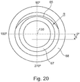
- FIG. 20 a second parameterization for the description of the geometry of the spherical contact surface 60.
- these parametrizations are only to be understood as examples.
- the parameterization of FIG. 19 considered.
- the angle ⁇ the circumferential angle over which the spherical area is pronounced in the circumferential direction.
- the FIGS. 15 . 16 and 18 it can be seen that the circumferential angle ⁇ in the illustrated embodiment is not constant in the circumferential direction, but varies depending on the axial position between the two ends 65, 66. In other exemplary embodiments it can be provided that the extent area in the circumferential direction or the angle ⁇ is constant.
- the variation of the extent of the spherical contact surface 60 in the circumferential direction is such that the convex contact surface 60 at the axial ends 65, 66 of the contact surface 60 extends over a larger circumferential angle ⁇ than in the region 62 of the maximum outer diameter D.
- the spherically formed contact surface 60 in the cylindrical portion 62 constant outside diameter on a convex contact surface 60, which extends over a minimum circumferential angle ⁇ 1, see.
- FIG. 18 Starting from this minimum circumferential angle ⁇ 1, the circumferential angle ⁇ to the axial ends 65, 66 of the contact surface 60 increases continuously to a maximum circumferential angle ⁇ 2.
- the two boundary lines 610, 620 of the ball-shaped contact surface 60 have a minimum distance in the region 62 of the maximum outside diameter D and a maximum distance at the axial ends 65, 66.
- the boundary lines 610, 620 are formed symmetrically with respect to the axial center 95, respectively.
- the boundary lines 610, 620 are mirror-symmetrical with respect to a straight line which extends in the axial direction between them (and which in the illustration of FIG. 18 in the projection from above on the central axis 130).
- the angle ⁇ is 120 °, so can over the Be given angle ⁇ that the angle ⁇ , for example, in the angular range between 180 ° and 240 °, ie in the third quarter extends (180 ° ⁇ ⁇ ⁇ 240 °), wherein the angle ⁇ in the mathematically positive sense of rotation is measured and the x-axis of the Cartesian coordinate system defines the angle 0 °.
- the orientation of the crown along the circumference is arbitrary and depends on the installation position.
- the FIG. 19 shows as a further parameter the height h of the crown.
- the height h of the crown is not a constant, but decreases with increasing distance from the center between the two boundary lines 610, 620 to the boundary lines 610, 620 out. This ensures that the transition between the cylindrical portion 600 of the planetary slide bearing pin 6 and the spherically formed portion 60 without a sudden change in thickness occurs.
- the boundary lines 610, 620 represent only light edges that indicate the transition from the crowned area to the cylindrical area.
- the angle ⁇ is for example in the range between 10 ° and 350 °. In particular, this angle can be in the range between 10 ° and 180 °. For example, it is in the range between 10 ° and 120 °, in particular in the range between 30 ° and 80 °.
- the angular difference between ⁇ 1 and ⁇ 2 is, for example, in the range between 10 ° and 120 °, in particular in the range between 40 ° and 80 °.
- angle ⁇ is smaller than 180 °, more than one ball-shaped contact surface 60 can be realized in the circumferential direction.
- FIG. 20 shows as well as the FIG. 19 the planetary slide pin 6 in a view from the left front. Only a different parameterization is indicated.
- the parameterization takes place via the radius R of the crown in the circumferential direction at the axial ends 65, 66 in conjunction with an eccentricity E.
- the eccentricity indicates the distance between the central axis of the parameter "radius" and the central axis of the sliding bearing pin.
- the greater the height h of the crowning the smaller the curvature in the circumferential direction at the ends 65, 66, the greater the radius of the associated circle and, accordingly, the greater the eccentricity E.
- the eccentricity E is thus a parameter for the Crown of the bearing surface 60 of the planetary plain bearing pin 6.
- the radius R is constant in the circumferential direction.
- the radius R varies only in the axial direction.
- the radius is greatest in the cylindrical portion 62 of constant outer diameter and decreases toward the axial ends 65, 66.
- the radius R in the middle between the two boundary lines 610, 620 is maximum and gradually decreases towards the boundary lines 610, 620 until the radius of the cylindrical region 600 is reached.
- a tangential transition between the regions 60 and 600 is achieved.
- Such a tangential transition is not given at constant radius R in the circumferential direction.
- the radius R is generally considered to be greater than or equal to D / 2, cf. FIG. 17 with the radius R decreasing toward the axial ends 65, 66.
- FIG. 11 shows a further embodiment of a planetary plain bearing pin 6, which forms a sliding bearing with a planetary gear 4 with an external toothing 45.
- the planet slide bearing pin 6 is fixedly connected to a structure corresponding to the embodiment of the FIGS. 4 and 5 consists of a front support plate 810, a rear support plate 820 and a torque carrier 70.
- the planet slide pin 6 comprises a first axial extension 67 fixed in the front support plate 810 and a second axial extension 68 fixed in the rear support plate 820.
- the torque arm 70 is connected via connecting webs 76 fixed to the front support plate 810. In this respect, the description of the FIGS. 4 and 5 directed.
- the planetary slide pin 6 has a ball-shaped bearing surface 60, as with respect to the FIG. 6 has been explained.
- the planetary slide pin 6 further has an inner surface 69 to the axial bore 690, which has a shape deviating from a cylindrical shape.
- the bore 690 is formed double conical, wherein the inner diameter of the bore 690 in the axial center 95 of the Planet slide bearing pin 6 a minimum and to the two axial ends has a maximum.
- the bore 690 is cylindrical.
- FIG. 12 shows the planetary plain bearing pin 6 of FIG. 11 in an enlarged view, wherein according to the representation of FIG. 6 the there given, relevant for the formation of the planetary slide bearing pin 6 parameters D, d, e, f, h, P and L are also shown. With regard to the definition of these parameters, reference is made to the description of FIG. 6 directed. Unlike in the FIG. 6 is merely assumed that the minimum outer diameter of the planetary plain bearing pin 6 at the two axial ends is identical, so that this parameter is indicated by d (without the in the FIG. 6 made differentiation between d1 and d2 and, accordingly, also without the differentiation between h1 and h2).
- the two axial ends 67, 68 may have a different shape, as in the FIGS. 11 and 12 is shown.
- FIGS. 13 and 14 illustrating, respectively, the lubricant film thickness of the sliding bearing in dependence on the axial position of the sliding bearing.
- the FIG. 14 shows the conditions on a planetary plain bearing pin, which has a purely cylindrical shaped, not crowned outer surface, at 80% load. It can be seen that the lubricating film thickness decreases sharply toward the axial ends (see arrows A, B), resulting in increased lubricating film pressure and the risk of metal-to-metal contact between the planetary journal bearing pin and the planetary gear.
- FIG. 13 FIG. 12 shows the lubricating film thickness of the sliding bearing as a function of the axial position of the sliding bearing for a planetary plain bearing pin having a crowned outer surface at 100% load. A sufficient lubricant film thickness is also given at the axial ends.
- the present invention is not limited in its embodiment to the embodiments described above.
- the described concrete shapes of the planetary plain bearing pin are to be understood as exemplary only.
Landscapes
- Engineering & Computer Science (AREA)
- General Engineering & Computer Science (AREA)
- Mechanical Engineering (AREA)
- Chemical & Material Sciences (AREA)
- Combustion & Propulsion (AREA)
- Oil, Petroleum & Natural Gas (AREA)
- Retarders (AREA)
- General Details Of Gearings (AREA)
Abstract
Description
- Die Erfindung betrifft ein Planetengetriebe gemäß dem Oberbegriff des Patentanspruchs 1 und einen Gleitlagerstift für ein solches Planetengetriebe.
- Planetengetriebe sind allgemein bekannt. Sie werden unter anderem in Getriebefan-Triebwerken eingesetzt, um eine Untersetzung zwischen einer mit einer Turbine gekoppelten Turbinenwelle und einer mit einem Fan gekoppelten Fanwelle bereitzustellen.
- Die
US 2015/0300255 A1 beschreibt ein Planetengetriebe eines Getriebefan-Triebwerks, bei dem in Planetenrädern, die von einem Sonnenrad angetrieben werden und in einem feststehenden Hohlrad umlaufen, jeweils zylindrische Planeten-Gleitlagerstifte angeordnet sind, die ein geschmiertes Gleitlager zum Planetenrad bilden. Die Planeten-Gleitlagerstifte sind mit einem Drehmomentträger verbunden, der mit einer Fanwelle gekoppelt ist. - In Getriebefan-Triebwerken sind Planetengetriebe sehr großen Zentrifugalkräften und Drehmomenten ausgesetzt, die den Planeten-Gleitlagerstift und das Planetenrad verformen und den Schmierfilm im Gleitlager zwischen diesen beiden Elementen beeinflussen können, wodurch die Funktionalität des Gleitlagers beeinträchtigt wird. Insbesondere verhält es sich so, dass der zylindrische und an seinen Enden in Trägerplatten fixierte Planeten-Gleitlagerstift durch die auftretenden Kräfte Biegungen ausgesetzt ist, durch die die Schmierfilmdicke in der Mitte des Planeten-Gleitlagerstifts zunimmt und an den Enden des Planeten-Gleitlagerstifts abnimmt, was an den Enden des Planeten-Gleitlagerstifts zu einem erhöhten Schmierfilmdruck und der Gefahr eines Metall-Metall-Kontaktes zwischen dem Planeten-Gleitlagerstift und dem Planetenrad führt. Eine starke Belastung und Abnutzung des Planeten-Gleitlagerstifts an seinen Enden sind die Folge.
- Durch eine verbesserte Steifigkeit des Planeten-Gleitlagerstifts könnten dessen Belastungen und Abnutzungen reduziert werden. Die hierfür erforderliche Vergrößerung der Wanddicke des Planeten-Gleitlagerstifts führt jedoch zu einer Gewichtszunahme, die bei Luftfahrtanwendungen nachteilig ist.
- Der vorliegenden Erfindung liegt die Aufgabe zu Grunde, ein Planetengetriebe mit einem verschleißarmen Planeten-Gleitlagerstift sowie einen Gleitlagerstift für ein solches Planetengetriebe bereitzustellen.
- Diese Aufgabe wird durch ein Planetengetriebe mit den Merkmalen des Patentanspruchs 1 und einen Gleitlagerstift mit den Merkmalen des Patentanspruchs 14 gelöst. Ausgestaltungen der Erfindung sind in den abhängigen Ansprüchen angegeben.
- Danach betrachtet die Erfindung ein Planetengetriebe, das ein Sonnenrad, eine Mehrzahl von Planetenrädern, ein Hohlrad und eine Mehrzahl von Planeten-Gleitlagerstiften umfasst. Das Sonnenrad rotiert um eine Drehachse des Planetengetriebes und wird von einer Sonnenwelle angetrieben. Die Drehachse des Planetengetriebes definiert eine axiale Richtung des Planetengetriebes. Die Planetenräder werden von dem Sonnenrad angetrieben und stehen mit dem Hohlrad in Eingriff. Die Planeten-Gleitlagerstifte weisen jeweils eine außenseitige Anlagefläche auf, die ein axial vorderes Ende und ein axial hinteres Ende aufweist. Ein Planeten-Gleitlagerstift ist jeweils in einer axialen Öffnung eines Planetenrads angeordnet. Der Planeten-Gleitlagerstift und das Planetenrad bilden ein geschmiertes Gleitlager, wobei die aneinander angrenzende Kontaktflächen des Gleitlagers durch einen Gleitlagerspalt voneinander getrennt sind.
- Die vorliegende Erfindung sieht vor, dass die Planeten-Gleitlagerstifte an ihrer Anlagefläche eine Balligkeit in dem Sinne ausbilden, dass ihr Außendurchmesser von einem maximalen Außendurchmesser zu mindestens einem axialen Ende der Anlagefläche hin abnimmt und an dem axialen Ende ein Minimum aufweist. Die mit einer Balligkeit ausgebildete Anlagefläche des Planeten-Gleitlagerstifts bildet dabei eine Kontaktfläche des Gleitlagers, das der Planeten-Gleitlagerstift mit dem Planetenrad bildet.
- Die erfindungsgemäße Lösung beruht auf der Idee, den Planeten-Gleitlagerstift nicht mehr zylindrisch auszubilden, sondern mit einer Balligkeit zu versehen, die dazu führt, dass der Außendurchmesser des Planeten-Gleitlagerstifts an mindestens einem axialen Ende der Anlagefläche minimal ist. Hierdurch wird an mindestens einem Ende der Anlagefläche ein vergrößerter Gleitlagerspalt und damit einhergehend eine vergrößerte Schmierfilmdicke bereitgestellt. Dies führt dazu, dass bei im Betrieb auftretenden Deformationen und Schwingungen an den Enden der Anlagefläche, die auf Zentrifugalkräfte und eingeleitete Drehmomente zurückzuführen sind, die Schmierfilmdicke an mindestens einem axialen Ende der Anlagefläche ausreichend groß bleibt, um einen überhöhten Schmierfilmdruck und die Gefahr eines Metall-Metall-Kontaktes zwischen dem Planeten-Gleitlagerstift und dem Planetenrad zu vermeiden.
- Durch die Erfindung wird das Gleitlager insofern optimiert, als auch an den axialen Enden des Gleitlagers im Betrieb parallel ausgerichtete Kontaktflächen bereitgestellt werden. Die Schmierfilmdicke weist geringere Dickenänderungen über die axiale Länge auf. Die genannten Vorteile werden dabei ohne eine Erhöhung der Wanddicke des Planeten-Gleitlagerstifts erreicht. Vielmehr kann sogar eine gewisse Gewichtsersparnis erreicht werden, da die Balligkeit der Anlagefläche durch eine Materialentfernung zu den axialen Enden der Anlagefläche hin erreicht werden kann.
- Eine Ausgestaltung der Erfindung sieht vor, dass die Planeten-Gleitlagerstifte an ihrer Anlagefläche eine Balligkeit dahingehend ausbilden, dass ihr Außendurchmesser zu beiden axialen Enden der Anlagefläche hin abnimmt und an beiden axialen Enden ein Minimum aufweist. Insbesondere kann vorgesehen sein, dass der Planeten-Gleitlagerstift minimale Außendurchmesser an den beiden axialen Enden der Anlagefläche und den maximalen Außendurchmesser zwischen den axialen Enden aufweist, wobei die minimalen Außendurchmesser an den beiden Enden identisch oder unterschiedlich sein können. Dabei definiert die Differenz zwischen dem maximalen Außendurchmesser und dem minimalen Außendurchmesser an dem einen Ende der Anlagefläche die Balligkeit zwischen dem maximalen Außendurchmesser und dem einen Ende. Des Weiteren definiert die Differenz zwischen dem maximalen Außendurchmesser und dem minimalen Außendurchmesser an dem anderen Ende der Anlagefläche die Balligkeit zwischen dem maximalen Außendurchmesser und dem anderen Ende.
- Der Außendurchmesser ist gemäß dieser Ausführungsvariante somit an beiden axialen Enden minimal, d. h. er nimmt zu beiden axialen Enden ab. Damit ist gerade nicht vorgesehen, dass der Außendurchmesser angrenzend an die axialen Enden konstant verläuft, für welchen Fall die axialen Enden zylindrisch ausgebildet wären. Gemäß einer alternativen Ausgestaltung weist der Außendurchmesser an dem einen axialen Ende der Anlagefläche einen maximalen Außendurchmesser auf, wobei sich der Außendurchmesser zu dem anderen axialen Ende hin kontinuierlich bis zu einem Minimum verringert.
- Dementsprechend kann vorgesehen sein, dass die Differenz zwischen dem maximalen Außendurchmesser und dem Außendurchmesser an einer betrachteten axialen Position des Planeten-Gleitlagerstifts zu beiden axialen Enden oder zu einem axialen Ende des Planeten-Gleitlagerstifts kontinuierlich zunimmt. Dies bedeutet für den Gleitlagerspalt, dass dieser - bei einer Betrachtung des Zusammenbauzustands ohne Last und im nichtrotierenden Zustand - ebenfalls zu den axialen Enden des Planeten-Gleitlagerstifts zunimmt. Dabei wird angenommen, dass die Kontaktfläche des Planetenrads, die die andere Fläche des Gleitlagers bildet, zylindrisch ausgebildet ist. Im Betrieb bzw. unter Last schmiegt sich das Planetenrad dagegen an den Planeten-Gleitlagerstift, so dass ein gleichmäßiger Spalt über die axiale Länge entsteht.
- Eine weitere Ausgestaltung der Erfindung sieht vor, dass die Anlagefläche des Planeten-Gleitlagerstifts im Längsschnitt eine erste konvexe Kurve ausbildet, die sich zwischen dem Maximum des Außendurchmessers und dem vorderen axialen Ende der Anlagefläche erstreckt, und eine zweite konvexe Kurve ausbildet, die sich zwischen dem Maximum des Außendurchmessers und dem hinteren axialen Ende der Anlagefläche erstreckt. Dabei kann die konvexe Kurve grundsätzlich in beliebiger Weise geformt sein. Ausführungsbeispiele sehen vor, dass die erste Kurve und/oder die zweite Kurve als Kreisbogen ausgebildet ist, dass die erste Kurve und/oder die zweite Kurve parabelförmig ausgebildet ist, oder dass die erste Kurve und/oder die zweite Kurve geradlinig ausgebildete Kurvenstücke aufweist. Im letzten Fall läuft beispielsweise die Anlagefläche des Planeten-Gleitlagerstifts zu seinen axialen Enden konisch zusammen. Auch kann vorgesehen sein, dass die erste Kurve und/oder die zweite Kurve aus mehreren unterschiedlich gekrümmten Kurvenstücken zusammengesetzt ist. Dabei kann weiter vorgesehen sein, dass eines oder mehrere dieser Kurvenstücke geradlinig/linear ausgebildet sind.
- Das Maximum des Außendurchmessers des Planeten-Gleitlagerstifts wird in einer Ausgestaltung der Erfindung durch eine Umfangslinie gebildet (die sich in Umfangsrichtung des Planeten-Gleitlagerstifts erstreckt). Im Längsschnitt des Planeten-Gleitlagerstifts bildet das Maximum somit einen Punkt. Dies bedeutet, dass die genannte erste Kurve und die genannte zweite Kurve stetig ineinander übergehen, somit die Anlagefläche durch eine einzige gekrümmte Kurve gebildet sein kann (die ins Ausführungsvarianten aus unterschiedlich gekrümmten Kurvenstücken zusammengesetzt sein kann). Dementsprechend kann in Ausgestaltungen der Erfindung vorgesehen sein, dass die Anlagefläche des Planeten-Gleitlagerstifts vollständig kreisförmig oder parabelförmig mit einem Maximum des Außendurchmessers in der axialen Mitte des Planeten-Gleitlagerstifts oder alternativ außerhalb der axialen Mitte des Planeten-Gleitlagerstifts ausgebildet ist.
- Eine alternative Ausgestaltung der Erfindung sieht vor, dass das Maximum des Außendurchmessers des Planeten-Gleitlagerstifts durch einen zylindrischen Bereich konstanten Außendurchmessers gebildet ist, der sich über eine definierte axiale Länge erstreckt. Diese axiale Länge ist gemäß einer Ausführungsvariante derart bemessen, dass das Verhältnis der axialen Länge des zylindrischen Bereichs zur axialen Gesamtlänge der Anlagefläche zwischen 0 und 0,75 liegt.
- Ein solcher zylindrischer Plateaubereich kann dabei mittig oder außermittig ausgebildet sein. An ihn können sich beispielsweise im Längsschnitt kreisförmige, parabelförmige oder gradlinige Flächen anschließen.
- Eine Ausgestaltung der Erfindung sieht vor, dass das Verhältnis der halben Differenz zwischen dem maximalen Außendurchmesser und dem minimalen Außendurchmesser des Planeten-Gleitlagerstifts zum maximalen Außendurchmesser zwischen 0,00005 und 0,005 liegt. Genannte halben Differenz gibt dabei gerade die Balligkeit des Planeten-Gleitlagerstifts an. Sofern der Planeten-Gleitlagerstift unterschiedliche minimale Außendurchmesser an den beiden axialen Enden der Anlagefläche aufweist, gilt das genannte Verhältnis jeweils im Hinblick auf den maximalen Außendurchmesser und den minimalen Außendurchmesser an dem jeweils betrachteten axialen Ende.
- Weitere Varianten der Erfindung sehen vor, dass der Planeten-Gleitlagerstift in seiner axialen Mitte (d.h. mittig zwischen dem axial vorderen Ende und dem axial hinteren Ende der Anlagefläche) ein Maximum seines Außendurchmessers aufweist. Der Planeten-Gleitlagerstift ist spiegelsymmetrisch hinsichtlich seiner axialen Mitte ausgebildet. Dies ist jedoch nicht notwendigerweise der Fall. Alternative Varianten der Erfindung sehen vor, dass der Planeten-Gleitlagerstift außerhalb seiner axialen Mitte ein Maximum seines Außendurchmessers aufweist und dementsprechend asymmetrisch hinsichtlich seiner axialen Mitte ausgebildet ist.
- Gemäß einer Ausgestaltung der Erfindung ist der Planeten-Gleitlagerstift als Rotationskörper ausgebildet, d. h. er ist rotationssymmetrisch bezüglich der Längsachse des Gleitlagerstifts ausgebildet. Dies ist jedoch nicht notwendigerweise der Fall. Gemäß alternativen Ausgestaltungen weist der Planeten-Gleitlagerstift eine ballig ausgebildete Anlagefläche lediglich über einen Umfangswinkel kleiner 360°, insbesondere im Bereich von ±60° um den nominell belasteten Bereich auf. Das erfindungsgemäße ballige Profil des Planeten-Gleitlagerstifts erstreckt sich somit nicht über den gesamten Umfang des Planeten-Gleitlagerstifts, sondern in Umfangsrichtung nur über einen definierten Winkelbereich. Der beschriebene positive Einfluss auf das Gleitlager ist auch bei einer solchen Ausgestaltung gegeben. Zusätzlich wird der Ölverbrauch für die Schmierung reduziert, da eine vergrößerte Schmierfilmdicke an den axialen Enden nicht über den gesamten Umfang bereitgestellt wird.
- Eine Ausführungsvariante einer ballig ausgebildeten Anlagefläche, die sich über einen Umfangswinkel kleiner 360° erstreckt, sieht vor, dass der Umfangswinkel, über den die ballig ausgebildete Anlagefläche sich erstreckt, in axialer Richtung des Planeten-Gleitlagerstifts variiert. Eine vergrößerte Schmierfilmdicke kann dadurch exakt abhängig von der axialen Position eingestellt werden.
- Dabei sieht eine Ausgestaltung vor, dass die ballig ausgebildete Anlagefläche sich am maximalen Außendurchmesser über einen minimalen Umfangswinkel erstreckt und der Umfangswinkel, über den die ballig ausgebildete Anlagefläche sich erstreckt, sich vom maximalen Außendurchmesser zu den axialen Enden der Anlagefläche hin stetig zu einem maximalen Umfangswinkel vergrößert, so dass die ballig ausgebildete Anlagefläche sich an den axialen Enden der Anlagefläche über einen größeren Umfangswinkel erstreckt als im Bereich des maximalen Außendurchmessers. Dabei kann vorgesehen sein, dass der maximale Außendurchmesser in einem zylindrischen Bereich realisiert ist. Weiter kann vorgesehen sein, dass die radiale Höhe der Balligkeit in Umfangsrichtung zu den Begrenzungslinien der ballig ausgebildeten Anlagefläche hin abnimmt.
- Sofern der Planeten-Gleitlagerstift rotationssymmetrisch ausgebildet ist, ist der Außendurchmesser an einer betrachteten axialen Position für alle Punkte einer Umfangslinie der gleiche. Sofern der Planeten-Gleitlagerstift nicht rotationssymmetrisch ausgebildet ist, wird als Außendurchmesser einer betrachteten axialen Position im Sinne der vorliegenden Erfindung der größte Außendurchmesser betrachtet.
- Der Planeten-Gleitlagerstift weist gemäß einer Ausgestaltung der Erfindung ein axial vorderes Ende und ein axial hinteres Ende auf, die axial beabstandet zu dem axial vorderen Ende und dem axial hinteren Ende der Anlagefläche sind, wobei der Planeten-Gleitlagerstift an seinem vorderen axialen Ende mit einer vorderen Trägerplatte und an seinem hinteren axialen Ende mit einer hinteren Trägerplatte verbunden ist. Der Planeten-Gleitlagerstift erstreckt sich somit an beiden Enden jenseits der Anlagefläche und ist dort jeweils mit einer Trägerplatte verbunden. Es ist also zu unterscheiden zwischen den axialen Enden der Anlagefläche und den axialen Enden des Planeten-Gleitlagerstifts.
- Eine weitere Ausgestaltung der Erfindung sieht vor, dass die Planeten-Gleitlagerstifte innenseitig eine axiale Öffnung aufweisen und dazu ausgebildet sind, einen Trägerstift eines Drehmomentträgers darin aufzunehmen.
- Gemäß einer Ausgestaltung der Erfindung sind die Planeten-Gleitlagerstifte mit einem Drehmomentträger gekoppelt, wobei der Drehmomentträger bei drehendem Sonnenrad und fest angeordnetem Hohlrad mit untersetzter Drehzahl um die Drehachse des Planetengetriebes rotiert. Der Drehmomentträger ist dabei beispielsweise mit einer Fanwelle gekoppelt. Die Planetenräder rotieren sowohl um ihre eigene Achse als auch um die Drehachse des Planetengetriebes, dies jeweils mit unterschiedlichen Drehzahlen.
- Eine Ausgestaltung der Erfindung sieht dabei vor, dass die Planeten-Gleitlagerstifte innen hohl und dazu ausgebildet sind, einen Trägerstift eines Drehmomentträgers aufzunehmen, wobei über den Trägerstift eine Drehmomentübertragung erfolgt.
- Alternativ kann vorgesehen sein, dass die Planeten-Gleitlagerstifte fest mit einer vorderen Trägerplatte und mit einer hinteren Trägerplatte verbunden sind, wobei die vordere Trägerplatte zur Drehmomentübertragung mit dem Drehmomentträger gekoppelt ist. Die Planeten-Gleitlagerstifte können mit den Trägerplatten dabei beispielsweise verschweißt oder verschraubt sein.
- Eine weitere Ausgestaltung der Erfindung sieht vor, dass die Planeten-Gleitlagerstifte einschließlich der ballig ausgebildeten Anlagefläche einstückig ausgebildet sind. Es handelt sich somit um einteilige Komponenten.
- Der Planeten-Gleitlagerstift der vorliegenden Erfindung weist eine ballig ausgebildete außenseitigen Anlagefläche auf. Der in der Regel hohl, d. h. mit einer axialen Öffnung bzw. Bohrung versehene Planeten-Gleitlagerstift kann dabei an seiner Innenfläche grundsätzlich beliebig ausgebildet sein. Beispielsweise kann der Planeten-Gleitlagerstift innenseitig hohlzylindrisch ausgebildet sein, also eine axiale Öffnung konstanten Durchmessers aufweisen. In anderen Ausführungsvarianten kann vorgesehen sein, dass der Innendurchmesser des Planeten-Gleitlagerstifts entlang seiner axialen Erstreckung variiert.
- Die Erfindung betrifft in einem weiteren Erfindungsaspekt einen Gleitlagerstift für ein Planetengetriebe, der eine außenseitige Anlagefläche für ein Gleitlager mit einem axial vorderen Ende und einem axial hinteren Ende aufweist, wobei der Planeten-Gleitlagerstift an seiner Anlagefläche eine Balligkeit in dem Sinne ausbildet, dass sein Außendurchmesser von einem maximalen Außendurchmesser zu mindestens einem axialen Ende der Anlagefläche hin abnimmt und an dem axialen Ende ein Minimum aufweist. Die in Bezug auf das Planetengetriebe erläuterten vorteilhaften Ausgestaltungen gemäß den Patentansprüchen 2 bis 13 gelten auch für den Gleitlagerstift. Grundsätzlich kann der Gleitlagerstift in beliebigen Getrieben mit Gleitlager Einsatz finden.
- In einem weiteren Erfindungsaspekt betrifft die Erfindung ein Getriebefan-Triebwerk, das eine Fanstufe, eine Fanwelle, über die die Fanstufe angetrieben wird, und eine Turbinenwelle umfasst. Bei der Turbinenwelle handelt es sich beispielsweise um eine Welle, die mit einer Niederdruckturbine oder einer Mitteldruckturbine des Triebwerks gekoppelt ist. Es ist vorgesehen, dass die Turbinenwelle und die Fanwelle über ein Planetengetriebe gemäß Anspruch 1 gekoppelt sind, wobei die Turbinenwelle die Sonnenwelle bildet, die Planeten-Gleitlagerstifte mit einem Drehmomentträger gekoppelt sind und der Drehmomentträger mit der Fanwelle gekoppelt ist.
- Es wird darauf hingewiesen, dass die vorliegende Erfindung bezogen auf ein zylindrisches Koordinatensystem beschrieben ist, das die Koordinaten x, r und ϕ aufweist. Dabei gibt x die axiale Richtung, r die radiale Richtung und ϕ den Winkel in Umfangsrichtung an. Die axiale Richtung ist dabei durch die Drehachse des Planetengetriebes definiert, die identisch mit einer Maschinenachse eines Getriebefan-Triebwerks ist, in dem das Planetengetriebe angeordnet ist. Von der x-Achse ausgehend zeigt die radiale Richtung radial nach außen. Begriffe wie "vor", "hinter", "vordere" und "hintere" beziehen sich auf die axiale Richtung bzw. die Strömungsrichtung im Triebwerk, in dem das Planetengetriebe angeordnet ist. Begriffe wie "äußere" oder "innere" beziehen sich auf die radiale Richtung.
- Die Erfindung wird nachfolgend unter Bezugnahme auf die Figuren der Zeichnung anhand mehrerer Ausführungsbeispiele näher erläutert. Es zeigen:
- Figur 1
- eine vereinfachte schematische Schnittdarstellung eines Getriebefan-Triebwerks;
- Figur 2
- eine Schnittdarstellung von Elementen eines Planetengetriebes, das zum Einsatz in einem Getriebefantriebwerk geeignet ist, wobei eine Sonnenwelle, ein Sonnenrad, ein Planetenrad, ein Planeten-Gleitlagerstift und ein Trägerstift eines Drehmomentträgers dargestellt sind, und wobei der Planeten-Gleitlagerstift an seiner Anlagefläche eine Balligkeit ausbildet;
- Figur 3
- eine vergrößerte Darstellung des Planetenrads und des Planeten-Gleitlagerstifts der
Figur 2 ; - Figur 4
- eine Darstellung von Elementen eines alternativen Planetengetriebes, bei dem anders als bei dem Planetengetriebe der
Figuren 2 und3 kein Trägerstift vorgesehen ist und stattdessen eine Drehmomentübertragung auf einen Drehmomentträger über eine fest mit den Planeten-Gleitlagerstiften verbundene Trägerplatte erfolgt; - Figur 5
- Elemente des Planetengetriebes der
Figur 4 in einer teilweise geschnittenen Ansicht; - Figur 6
- eine Schnitterstellung eines Planeten-Gleitlagerstifts gemäß den
Figuren 2 und3 ; - Figur 7
- eine Schnitterstellung eines weiteren Ausführungsbeispiels eines mit einer Balligkeit versehenen Planeten-Gleitlagerstifts, wobei der Planeten-Gleitlagerstift eine kreisbogenförmige Anlagefläche bildet;
- Figur 8
- eine Schnitterstellung eines weiteren Ausführungsbeispiels eines mit einer Balligkeit versehenen Planeten-Gleitlagerstifts, wobei der Planeten-Gleitlagerstift eine asymmetrisch ausgebildete Anlagefläche bildet;
- Figur 9
- eine Schnitterstellung eines weiteren Ausführungsbeispiels eines mit einer Balligkeit versehenen Planeten-Gleitlagerstifts, wobei der Planeten-Gleitlagerstift symmetrisch ausgebildet ist und die Anlagefläche unterschiedlich geformte Bereiche aufweist;
- Figur 10
- eine Schnitterstellung eines weiteren Ausführungsbeispiels eines mit einer Balligkeit versehenen Planeten-Gleitlagerstifts, wobei der Planeten-Gleitlagerstift asymmetrisch ausgebildet ist und die Anlagefläche unterschiedlich geformte Bereiche aufweist;
- Figur 11
- eine teilweise geschnittene Darstellung eines Planeten-Gleitlagerstifts, der in einem Planetengetriebe gemäß den
Figuren 4 und 5 angeordnet ist; - Figur 12
- den Planeten-Gleitlagerstift der
Figur 11 in vergrößerter geschnittener Darstellung; - Figur 13
- die Schmierfilmdicke eines Gleitlagers in Abhängigkeit von der axialen Position des Gleitlagers für einen Planeten-Gleitlagerstift mit ballig ausgebildeter Anlagefläche;
- Figur 14
- die Schmierfilmdicke eines Gleitlagers in Abhängigkeit von der axialen Position des Gleitlagers für einen zylindrisch geformten Planeten-Gleitlagerstift;
- Figur 15
- in perspektivischer Darstellung ein weiteres Ausführungsbeispiel eines Planeten-Gleitlagerstifts, wobei der Planeten-Gleitlagerstift eine ballig ausgebildete Anlagefläche über einen Umfangswinkel kleiner als 360° realisiert;
- Figur 16
- eine um 180° gedrehte perspektivische Darstellung des Ausführungsbeispiels der
Figur 15 ; - Figur 17
- eine Seitenansicht des Planeten-Gleitlagerstifts der
Figur 16 ; - Figur 18
- eine Ansicht von oben auf den Planeten-Gleitlagerstift der
Figur 16 ; - Figur 19
- eine Ansicht von links des Planeten-Gleitlagerstifts der
Figur 16 , wobei die Ansicht eine erste Parametrisierung im Hinblick auf die ballig ausgebildete Anlagefläche enthält; und - Figur 20
- eine Ansicht von links des Planeten-Gleitlagerstifts der
Figur 16 , wobei die Ansicht eine zweite Parametrisierung im Hinblick auf die ballig ausgebildete Anlagefläche enthält. - Die
Figur 1 zeigt ein Getriebefan-Triebwerk 10 mit einer Drehachse 11, das für eine Verwendung in Flugzeugen vorgesehen ist. In der Richtung der axialen Durchströmung weist das Getriebefan-Triebwerk 10 hintereinander einen Lufteinlauf 12, eine Fanstufe 13 (grundsätzlich sind auch mehr als eine Fanstufe 13 möglich), ein Getriebe 100, einen Mitteldruckverdichter 15, einen Hochdruckverdichter 16, eine Verbrennungsvorrichtung 17, eine Hochdruckturbine 18, eine Mitteldruckturbine 19 und eine Düse 20 auf. Ein Fangehäuse 21 umgibt die Fanstufe 13 und definiert den Lufteinlauf 12. - Das Getriebefan-Triebwerk 10 arbeitet grundsätzlich in konventioneller Weise, wobei in den Lufteinlauf 12 eintretende Luft von der Fanstufe 13 beschleunigt wird. Dabei werden zwei Luftstrome erzeugt: Ein erster Strom tritt in den Mitteldruckverdichter 15 ein, ein zweiter Luftstrom fließt durch einen Nebenstromkanal 22, wobei der zweite Luftstrom den größten Anteil am Schub des Getriebefan-Triebwerks 10 liefert. Der Mitteldruckverdichter 15 verdichtet den eintretenden Luftstrom, bevor er in den Hochdruckverdichter 16 gelangt, in dem eine weitere Verdichtung erfolgt. Die verdichtete Luft, die aus dem Hochdruckverdichter 16 austritt, wird in die Verbrennungsvorrichtung 17 geführt, wo sie mit Brennstoff vermischt wird und die Mischung dann zur Verbrennung gebracht wird. Die heißen Verbrennungsgase werden in der Hochdruckturbine 18 und in der Mitteldruckturbine 19 entspannt, bevor sie durch die Düse 20 austreten und somit zusätzlichen Schub liefern.
- Hinter dem Fanstufe 13 bildet das Getriebefan-Triebwerk 10 somit einen Nebenstromkanal 22 und einen Primärstromkanal aus. Der Primärstromkanal führt durch das Kerntriebwerk (Gasturbine), das den Mitteldruckverdichter 15, den Hochdruckverdichter 16, die Verbrennungsvorrichtung 17, die Hochdruckturbine 18 und die Mitteldruckturbine 19 umfasst. Der Nebenstromkanal 22 leitet im Betrieb des Getriebefan-Triebwerks 10 von der Fanstufe 13 angesaugte Luft am Kerntriebwerk vorbei.
- Die Hochdruckturbine 18 und die Mitteldruckturbine 19 treiben über Wellenvorrichtungen jeweils den Hochdruckverdichter 16 und den Mitteldruckverdichter 15 an. Eine Mitteldruckwelle treibt die Fanstufe 13 über das Getriebe 100 an. Das Getriebe 100 ist dabei als Untersetzungsgetriebe ausgebildet, das die Drehzahl der Fanstufe 13 im Vergleich zum Mitteldruckverdichter 15 und zur Mitteldruckturbine 19 reduziert. Das Getriebe 100 ist in der dargestellten Ausführungsform ein Planetengetriebe mit einem statischen Hohlrad 5 und umlaufenden Planetenrädern 4, die im Hohlrad 5 umlaufen. Der Antrieb des Getriebes 100 erfolgt über ein Sonnenrad 3, das mit der Mitteldruckwelle gekoppelt ist. Der Abtrieb erfolgt in der dargestellten Ausführungsform über einen Drehmomentträger 70, der mit den Planetenrädern 4 gekoppelt ist.
- Grundsätzlich sind auch andere Ausführungsformen des Getriebes 100 möglich, wobei z.B. das Hohlrad 5 beweglich ausgebildet sein kann, so dass der Abtrieb über das Hohlrad 5 erfolgt.
- Die Ausgestaltung des Getriebefan-Triebwerks 10 gemäß der
Figur 1 ist lediglich beispielhaft zu verstehen. Insbesondere die Anordnung der Wellen kann auch anders gewählt werden, wobei grundsätzlich Zwei- oder Dreiwellenanordnungen möglich sind. Beispielsweise kann alternativ eine Dreiwellenanordnung vorgesehen sein, die eine Niederdruckwelle, die die Niederdruckturbine mit dem Fan verbindet, eine Mitteldruckwelle, die die Mitteldruckturbine mit dem Mitteldruckverdichter verbindet, und eine Hochdruckwelle, die die Hochdruckturbine mit dem Hochdruckverdichter verbindet, umfasst. Dabei ist die Fanstufe 13 über ein Getriebe mit der Niederdruckwelle verbunden ist. Weiter können, wenn das Turbofantriebwerk keinen Mitteldruckverdichter und keine Mitteldruckturbine aufweist, nur eine Niederdruckwelle und eine Hochdruckwelle vorhanden sein, wobei wiederum die Fanstufe 13 über ein Getriebe mit der Niederdruckwelle verbunden ist. - Die beschriebenen Komponenten besitzen mit der Drehachse 11 eine gemeinsame Rotations- bzw. Maschinenachse. Die Drehachse 11 definiert eine axiale Richtung des Triebwerks 10. Eine radiale Richtung des Triebwerks 10 verläuft senkrecht zur axialen Richtung.
- Im Kontext der vorliegenden Erfindung ist die Ausbildung des Planetengetriebes 100 von Bedeutung.
- Die
Figur 2 zeigt ein Ausführungsbeispiel eines Planetengetriebes 100 in einer Schnittdarstellung. Das Planetengetriebe 100 umfasst ein Sonnenrad 3, das von einer Sonnenwelle 30 angetrieben wird. Bei der Sonnenwelle 30 handelt sich beispielsweise um die Mitteldruckwelle derFigur 1 . Das Sonnenrad 3 und die Sonnenwelle 30 drehen sich dabei um eine Drehachse 11, die eine axiale Richtung des Planetengetriebes 100 definiert. - Das Planetengetriebe 100 umfasst des Weiteren eine Mehrzahl von Planetenrädern 4, von denen in der Schnittdarstellung der
Figur 2 eines dargestellt ist. Das Sonnenrad 3 treibt die Mehrzahl der Planetenräder 4 an, wobei eine Verzahnung 35 des Sonnenrad 3 mit einer Verzahnung 45 des Planetenrads 4 in Eingriff steht. Bei der Verzahnung 35, 45 handelt es sich beispielsweise um eine Doppelschrägverzahnung. - Die folgende Beschreibung eines Planetenrads 4 gilt für sämtliche Planetenräder, die von dem Sonnenrad 3 angetrieben werden. Das Planetenrad 4 ist hohlzylindrisch ausgebildet und bildet eine äußere Mantelfläche und eine innere Mantelfläche 44. Das Planetenrad 4 rotiert - angetrieben durch das Sonnenrad 3 - um eine Drehachse 110, die parallel zur Drehachse 11 verläuft. Die äußere Mantelfläche des Planetenrads 4 bildet eine Verzahnung 45 aus, die mit der Verzahnung 55 eines Hohlrads 5 in Eingriff steht. Die Verzahnungen 45, 55 können ebenfalls als Doppelschrägverzahnung ausgebildet sein. Das Hohlrad 5 ist feststehend, d. h. nichtrotierend angeordnet. Die Planetenräder 4 rotieren aufgrund ihrer Kopplung mit dem Sonnenrad 3 und wandern dabei entlang des Umfangs des Hohlrads 5. Die Rotation der Planetenräder 4 entlang des Umfangs des Hohlrads 5 und dabei um die Drehachse 110 ist langsamer als die Rotation der Sonnenwelle 3, wodurch eine Untersetzung bereitgestellt wird.
- Das Planetenrad 4 weist angrenzend an seine innere Mantelfläche 44 eine zentrierte axiale Öffnung auf. In die Öffnung eingebracht ist ein Planeten-Gleitlagerstift 6, wobei der Planeten-Gleitlagerstift 6 und das Planetenrad 4 an ihren einander zugewandten Flächen ein geschmiertes Gleitlager bilden. Zur Schmierung des Gleitlagers können sich radial erstreckende Schmierfilmöffnungen 61 im Planeten-Gleitlagerstift 6 ausgebildet sein, durch die von innen eingesprühtes oder in anderer Weise zugeführtes Schmieröl in einen Gleitlagerspalt 9 zwischen dem Planeten-Gleitlagerstift 6 und dem Planetenrad 4 zugeführt werden kann. Dabei wird darauf hingewiesen, dass im Planeten-Gleitlagerstift 6 auch davon abweichende oder zusätzliche Mittel zum Zuführen von Schmieröl zum Gleitlager ausgebildet sein können.
- Im Betrieb weisen das Planetenrad 4 und der Planeten-Gleitlagerstift 6 nicht exakt die gleiche Achse auf, da das in hydrodynamischer Bauweise ausgeführte Gleitlager eine Exzentrizität im Bereich von Zehntelmillimetern mit sich bringt.
- Der Planeten-Gleitlagerstift 6 weist eine außenseitige Anlagefläche 60 auf, die ballig ausgebildet ist. Dementsprechend nimmt der Außendurchmesser des Planeten-Gleitlagerstifts zu den axialen Enden der Anlagefläche 60 hin ab und weist dort ein Minimum auf.
- Der Planeten-Gleitlagerstift 6 weist angrenzend an seine Innenfläche 69 ebenfalls eine axiale Öffnung bzw. Bohrung auf und ist dazu vorgesehen, in dieser einen Trägerstift 7 eines Drehmomentträgers aufzunehmen. Der Trägerstift 7 ist dabei in einem verjüngten Bereich 71 des Trägerstifts 7 in einem Gelenklager 73 innerhalb der Bohrung des Planeten-Gleitlagerstifts 6 gelagert. Das Gelenklager 73 erlaubt eine gewisse Schiefstellung des Trägerstiftes 7 gegenüber der Drehachse 110. Ein Trägerstift 7 ist in jedem der Planeten-Gleitlagerstifte 6 des Planetengetriebes 100 angeordnet. Die Trägerstifte 7 sind an ihren aus der Öffnung des Planeten-Gleitlagerstifts 6 herausragenden Enden fest miteinander verbunden und bilden dabei einen Drehmomentträger entsprechend dem Drehmomentträger 70 der
Figur 1 . Der Drehmomentträger bildet ein Abtriebselement des Planetengetriebes ist mit der Fanwelle bzw. allgemein mit einer Abtriebswelle gekoppelt. - Die genaue Form des Trägerstiftes 7 und dessen dargestellte Lagerung an der Innenfläche des Planeten-Gleitlagerstifts 6 sind dabei nur beispielhaft zu verstehen. Auch wird darauf hingewiesen, dass eine Kopplung des Planeten-Gleitlagerstifts 6 mit einem Drehmomentträger auch in anderer Weise erfolgen kann, wie anhand der
Figuren 4 und 5 beispielhaft aufgezeigt wird. - Die
Figur 2 zeigt des Weiteren eine vordere Trägerplatte 81 und eine hintere Trägerplatte 82. Der Planeten-Gleitlagerstift 6 ist mit der vorderen Trägerplatte 81 und mit der hinteren Trägerplatte 82 befestigt, beispielsweise mit diesen verschraubt oder verschweißt. Dazu ist vorgesehen, dass der Planeten-Gleitlagerstift 6 ein axial vorderes Ende 67 und ein axial hinteres Ende 68 aufweist, die jeweils axial gegenüber den Enden der Anlagefläche 60 hervorstehen, wobei der Planeten-Gleitlagerstift 6 an den Enden 67, 68 mit den Trägerplatten 81, 82 befestigt ist. - Der Aufbau des Planetenrads 4 und des Planeten-Gleitlagerstifts 6 wird nachfolgend weitergehend in Bezug auf die
Figur 3 erläutert, die einen Ausschnitt aus derFigur 2 darstellt. - Gemäß der
Figur 3 ist zu erkennen, dass das Planetenrad 4 an seinen beiden Stirnseiten 41, 42 jeweils eine Aussparung 401 ausbildet, die sich von der Stirnseite 41, 42 im Wesentlichen in axialer Richtung (bzw. ausgehend von der Stirnseite 41 entgegen der axialen Richtung) in das Innere des Planetenrads 4 erstreckt. Hierdurch werden die Masse des Planetenrads 4 und die Steifigkeit des Planetenrads 4 zu seinen Stirnseiten 41, 42 hin reduziert. - Das Gleitlager zwischen dem Planeten-Gleitlagerstift 6 und dem Planetenrad 4 wird durch die zylindrische innere Mantelfläche 44 des Planetenrads 4 und die mit einer Balligkeit versehene Anlagefläche 60 des Planeten-Gleitlagerstifts 6 gebildet. Der im Bereich des Gleitlagers ausgebildete Gleitlagerspalt 9 nimmt dabei aufgrund der Krümmung der Anlagefläche 60 zum axial vorderen Ende und zum axial hinteren Ende des Gleitlagers in seiner radialen Dicke zu. Bei hohen Drehmomenten und Zentrifugalkräften können sich die aneinander angrenzenden Flächen 44, 60 des Gleitlagers jedoch an dessen Enden im Wesentlichen parallel ausrichten. Hierzu tragen auch die in dem Planetenrad 4 ausgebildeten Aussparungen 401 bei, die diesem an seinen Enden eine erhöhte Flexibilität geben.
- Die Anlagefläche 60 weist ein axial vorderes Ende 65 und ein axial hinteres Ende 66 auf.
- Die
Figuren 4 und 5 zeigen Elemente eines weiteren Planetengetriebes. Das Planetengetriebe derFiguren 4 und 5 ist grundsätzlich wie das Planetengetriebe derFiguren 2 und3 aufgebaut. Es unterscheidet sich lediglich in der Art, in der das Drehmoment abgenommen und auf einen Drehmomentträger (entsprechend dem Drehmomentträger 70 derFigur 1 ) übertragen wird. DieFigur 4 zeigt nur solche Elemente des Planetengetriebes, die diese unterschiedliche Art der Drehmomentübertragung betreffen. Die übrigen, nicht dargestellten Elemente entsprechen der Ausgestaltung derFiguren 2 und3 . Insbesondere umfasst das Getriebe wie in Bezug auf dieFiguren 2 und3 erläutert ein Sonnenrad, eine Sonnenwelle, eine Mehrzahl von Planetenrädern, die von dem Sonnenrad angetrieben werden, und ein Hohlrad. - In den
Figuren 4 und 5 ist zu erkennen, dass die Planeten-Gleitlagerstifte 6 fest mit einer vorderen Trägerplatte 810 und einer hinteren Trägerplatte 820 verbunden sind. Sie sind mit den Trägerplatten 810, 820 beispielsweise fest verschraubt oder verschweißt. Der Planeten-Gleitlagerstift 6 weist ebenso wie im Ausführungsbeispiel derFiguren 2 und3 jeweils eine ballige außenseitige Anlagefläche 60 auf. An seiner Innenfläche 69 bildet der Planeten-Gleitlagerstift 6 eine Bohrung 690 aus, deren Innendurchmesser zur axialen Mitte des Planeten-Gleitlagerstifts hin abnimmt. Im dargestellten Ausführungsbeispiel ist die Bohrung 690 doppelt konisch ausgebildet. Hierauf wird in Bezug auf dieFiguren 17 und18 näher eingegangen werden. - Anders als beim Ausführungsbeispiel der
Figuren 2 und3 nimmt die axiale Bohrung 690 des Planeten-Gleitlagerstifts 6 keinen Trägerstift eines Drehmomentträgers auf, sondern ist leer. Ein Trägerstift ist nicht vorhanden. Die Übertragung eines Drehmoments auf einen Drehmomentträger 70 erfolgt über Verbindungsstege 76, die den Drehmomentträger 70 fest mit der vorderen Trägerplatte 810 verbinden. Der Drehmomentträger 70 ist im dargestellten Ausführungsbeispiel als Ring ausgebildet. Dies ist jedoch nur beispielhaft zu verstehen. Der Drehmomentträger 70 ist in nicht dargestellter Weise mit der Fanwelle gekoppelt. - Beim Ausführungsbeispiel der
Figuren 4 und 5 sind der Drehmomentträger 70, die vordere Trägerplatte 810 und die hintere Trägerplatte 820 einteilig ausgebildet, während sie beim Ausführungsbeispiel derFiguren 2 und3 dreiteilig ausgebildet sind. Durch die Zusammenführung des Drehmomentträgers und der Trägerplatten zu einem Teil kann der Trägerstift 7 derFiguren 2 und3 wegfallen. Die Abnahme des Drehmoments erfolgt nicht mehr mittig in der Bohrung des Planeten-Gleitlagerstifts 6, sondern von der vorderen Trägerplatte 810. Dementsprechend wird beim Ausführungsbeispiel derFiguren 4 und 5 auch kein Gelenklager (entsprechend dem Gelenklager 73 derFiguren 2 und3 ) benötigt. - Zum einteiligen Aufbau von vorderer Trägerplatte 810, hinterer Trägerplatte 820 und Drehmomentträger 70 wird weiter angemerkt, dass die vordere Trägerplatte 810 und die hintere Trägerplatte 820 durch am Umfang ausgebildete Wandflächen 830 miteinander verbunden sind, zwischen denen sich jeweils im wesentlichen rechteckförmige Aussparungen 840 befinden, die der Aufnahme jeweils eines Planetenrads dienen. Weiter weist die durch die beiden Trägerplatten 810, 820 und den Drehmomentträger 70 gebildete strukturelle Einheit axiale Bohrungen 77 auf, die der Ankopplung weiterer Teile (nicht dargestellt) für eine Drehmomentübertragung dienen können.
- Die dargestellte Anzahl von fünf Planeten-Gleitlagerstiften 6, fünf Verbindungsstegen 76 und fünf axialen Bohrungen 77 ist nur beispielhaft zu verstehen.
- Die
Figur 6 erläutert beispielhaft die Ausgestaltung und die relevanten Parameter eines Planeten-Gleitlagerstifts, der entsprechend einem Planeten-Gleitlagerstift 6 gemäß denFiguren 2 bis 5 ausgebildet ist. In der Schnittdarstellung derFigur 6 ist dabei eine Längsachse 130 des Planeten-Gleitlagerstifts 6 erkennbar. Diese ist im Wesentlichen identisch mit der Drehachse 110 des Planetenrads 110, vgl.Figur 2 , wobei jedoch die hydrodynamische Bauweise des Gleitlagers eine kleine Exzentrizität z.B. im Bereich von Zehntelmillimetern mit sich bringt. Der Planeten-Gleitlagerstift 6 bildet angrenzend an eine innere Mantelfläche bzw. Innenfläche 69 des Planeten-Gleitlagerstifts 6 eine axiale Öffnung 690 aus, die dazu dient, einen Trägerstift eines Drehmomentträgers aufzunehmen, beispielsweise den Trägerstift 7 derFigur 2 . - Der Planeten-Gleitlagerstift 6 bildet eine außenseitige Anlagefläche 60 aus, die ein axial vorderes Ende 65 und ein axial hinteres Ende 66 aufweist. Der axiale Abstand zwischen diesen beiden Enden wird mit L bezeichnet. Zwischen diesen beiden Enden 65, 66 bildet die Anlagefläche 60 eine Balligkeit in dem Sinne aus, dass ihr Außendurchmesser zu den axialen Enden 65, 66 hin abnimmt und an den axialen Enden 65, 66 ein Minimum erreicht.
- Der Planeten-Gleitlagerstift 6 weist dabei einen minimalen Außendurchmesser d1 an seinem axialen Ende 65, einen minimalen Außendurchmesser d2 an seinem axialen Ende 66 und einen maximalen Außendurchmesser D zwischen seinen axialen Enden 65, 66 auf. Dabei definiert die halbe Differenz h1 zwischen dem maximalen Außendurchmesser D und dem minimalen Außendurchmesser d1 die Balligkeit der Anlagefläche zwischen der axialen Position des maximalen Außendurchmessers und dem einen Ende 65. Weiter definiert die halbe Differenz h2 zwischen dem maximalen Außendurchmesser D und dem minimalen Außendurchmesser d2 die Balligkeit der Anlagefläche zwischen der axialen Position des maximalen Außendurchmessers und dem anderen Ende 66.
- Es kann vorgesehen sein, dass d1 gleich d2 oder alternativ dass d1 ungleich d2 ist. Dementsprechend ist h1 gleich h2 oder es ist h1 ungleich h2.
- Die Differenz zwischen dem maximalen Außendurchmesser D und dem Außendurchmesser e an einer betrachteten axialen Position des Planeten-Gleitlagerstifts nimmt zu den axialen Enden 65, 66 des Planeten-Gleitlagerstifts 6 stetig zu.
- Der maximale Außendurchmesser D ist im Ausführungsbeispiel der
Figur 6 an der axialen Mitte 95 des Planeten-Gleitlagerstifts 6 und in einem zylindrischen Bereich 62 der axialen Länge f um diese axiale Mitte 95 herum realisiert. Das Maximum des Außendurchmessers D ist somit in einem zylindrischen Bereich 62 konstanten Außendurchmessers realisiert, der sich symmetrisch zur axialen Mitte 95 über eine definierte axiale Länge f erstreckt. Dies ist allerdings nicht notwendigerweise der Fall. Alternativ wird das Maximum des Außendurchmessers D lediglich entlang einer Umfangslinie bzw. im in derFigur 6 dargestellten Längsschnitt an einem Scheitelpunkt erreicht. - Der axiale Abstand zwischen dem axial vorderen Ende 65 der Anlagefläche 60 zum Maximum des Außendurchmesser D oder, wenn das Maximum in einem zylindrischen Bereich ausgebildet ist, zur Mitte dieses zylindrischen Bereichs, wird in der
Figur 6 als P bezeichnet. In derFigur 6 liegt P dabei aufgrund der symmetrischen Ausgestaltung der Anlagefläche 60 in der axialen Mitte 95 der Anlagefläche. - Die Anlagefläche 60 des Planeten-Gleitlagerstifts 6 bildet im Längsschnitt eine erste konvexe Kurve 63 aus, die sich zwischen dem zylindrischen Bereich 62 und dem vorderen axialen Ende 65 erstreckt, sowie eine zweite konvexe Kurve 64 aus, die sich zwischen dem zylindrischen Bereich 62 und dem hinteren axialen Ende 66 erstreckt. Die Form der Kurven 63, 64 kann grundsätzlich beliebig sein. Beispielsweise sind die Kurven kreisförmig, parabelförmig oder gradlinig ausgebildet.
- Der Planeten-Gleitlagerstift 6 weist axiale Verlängerungen bzw. Enden 67, 68 auf, die jeweils eine vordere axialen Stirnseite 670 des Planeten-Gleitlagerstifts 6 und eine hintere axiale Stirnseite 680 des Planeten-Gleitlagerstifts bilden. Wie in Bezug auf die
Figuren 2 bis 5 erläutert, ist der Planeten-Gleitlagerstift 6 an diesen Enden 67, 68 jeweils an einer Trägerplatte befestigt. - Der Planeten-Gleitlagerstift 6 realisiert in Ausgestaltungen der Erfindung bestimmte Verhältnisse der wie oben definierten Parameter h, P, L und D.
- So gilt für das Verhältnis der Länge P zur axialen Gesamtlänge L: 0 ≤ P/L ≤ 1. Dies bedeutet, dass das Maximum des Außendurchmessers D grundsätzlich an beliebiger axialer Position des Planeten-Gleitlagerstifts 6 ausgebildet sein kann. Insbesondere sind auch asymmetrische Anordnungen möglich. Auch umfasst die Erfindung Ausführungsvarianten, bei denen das Maximum des Außendurchmessers D an dem einen axialen Ende 65 der Anlagefläche (P=0) oder an dem anderen axialen Ende 66 der Anlagefläche (P=L) ausgebildet ist. In anderen Ausführungsvarianten befindet sich das Maximum des Außendurchmessers D stets zwischen den beiden axialen Enden 65, 66 der Anlagefläche.
- Es gilt für das Verhältnis der axialen Länge des zylindrischen Bereichs f zur axialen Gesamtlänge L: 0 ≤ f/L ≤ 0,75. Je größer dieses Verhältnis, desto größer die axiale Erstreckung des zylindrischen Bereichs. Wenn das Verhältnis f/L gleich Null ist, ist f gleich Null, d. h. ein zylindrischer Bereich konstanten Außendurchmessers ist dann nicht vorhanden.
- Es gilt für das Verhältnis der halben Differenz h1, h2 zwischen dem maximalen Außendurchmesser D und dem minimalen Außendurchmesser d1, d2 zum maximalen Außendurchmesser D: 0,00005 ≤ h1/D ≤ 0,005 sowie 0,00005 ≤ h2/D ≤ 0,005. Diese Verhältnisse bestimmen die Balligkeit der Anlagefläche 60. Dabei kann h1 gleich h2 sein.
- Der in der
Figur 6 dargestellte Planeten-Gleitlagerstift 6 ist rotationssymmetrisch ausgebildet. - Die
Figuren 7-10 zeigen jeweils in einer Schnittdarstellung verschiedene Ausgestaltungen eines Planeten-Gleitlagerstifts 6 entsprechend dem Planeten-Gleitlagerstift derFigur 6 , wobei erkennbar ist, dass der Planeten-Gleitlagerstift 6 angrenzend an die Innenfläche 69 eine Öffnung 690 ausbildet, die entsprechend der Beschreibung derFiguren 2 und3 beispielsweise der Aufnahme eines Planeten-Gleitlagerstifts dient. - Die in Bezug auf die
Figur 6 erläuterten Parameter f, h, P und L sind dabei in denFiguren 7-10 unterschiedlich gewählt, wie im Folgenden ausgeführt wird. - Beim Ausführungsbeispiel der
Figur 7 ist die Anlagefläche 601 ohne einen zylindrischen Bereich ausgebildet, d. h. der Parameter f ist gleich Null. Dementsprechend ist der maximale Außendurchmesser D in der axialen Mitte 95 des Planeten-Gleitlagerstifts 6 realisiert. Die beiden konvexen Kurven 63, 64 derFigur 6 bilden eine gemeinsame Kurve, die beispielsweise durch einen Kreisbogen gebildet ist. - Der Planeten-Gleitlagerstift der
Figur 7 ist dabei spiegelsymmetrisch bezüglich seiner axialen Mitte 95 ausgebildet. - Beim Ausführungsbeispiel der
Figur 8 ist das Maximum des Außendurchmessers D außerhalb der axialen Mitte 95 realisiert, so dass eine Asymmetrie in der Formgebung der Anlagefläche 602 realisiert ist. Ein zylindrischer Bereich ist wiederum nicht vorgesehen. In der betrachteten Schnittdarstellung bilden die beiden konvexen Kurven 63, 64 derFigur 6 eine gemeinsame Kurve 602. Diese wird beispielsweise durch einen parabelförmigen Bogen gebildet. - Die
Figur 9 betrachtet ein Ausführungsbeispiel, bei dem die Anlagefläche 603 einen zylindrischen Bereich 62 ausbildet, in dem der Außendurchmesser D maximal ist. Dieser Bereich 62 ist mittig ausgebildet, so dass der Planeten-Gleitlagerstift 6 spiegelsymmetrisch bezüglich seiner axialen Mitte 95 ist. - Zu beiden Seiten angrenzend an den zylindrischen Bereich 62 bildet die Anlagefläche 603 Bereiche aus, die kreisförmig gebogen sind, wobei sich an diese Bereiche konisch geformte Bereiche anschließen, die sich bis zu den axialen Enden 65, 66 der Anlagefläche 603 erstrecken. In der Schnittdarstellung der
Figur 9 bildet die Anlagefläche dem kreisförmig gebogenen Bereich einen Kreisbogen 630 und dem konisch geformten Bereich einen gerade Linie 640 aus, wobei letzterer bis zu den axialen Enden 65, 66 der Anlagefläche 603 verläuft. - Die
Figur 10 zeigt ein Ausführungsbeispiel, bei dem das Maximum des Außendurchmessers D außerhalb der axialen Mitte 95 realisiert, so dass eine Asymmetrie in der Formgebung der Anlagefläche 604 realisiert ist. Die Anlagefläche 604 bildet dabei einen zylindrischen Bereich 62 aus, in dem der Außendurchmesser D maximal ist. Dieser Bereich 62 ist jedoch versetzt zu der axialen Mitte 95 des Planeten-Gleitlagerstifts 6 ausgebildet. Von dem zylindrischen Bereich 62 erstreckt ein parabelförmig gebogener Bereich bis zum axial vorderen Ende 65 der Anlagefläche 604, der in derFigur 10 eine parabelförmig Linie 650 bildet. Zwischen dem zylindrischen Bereich 62 und dem axial hinteren Ende 66 der Anlagefläche 604 sind zwei unterschiedlich geformte Bereiche ausgebildet, zunächst ein kreisförmig gebogener Bereich und daran anschließend und sich bis zum axialen Ende 66 erstreckender, konisch verjüngender Bereich, die in der Schnittdarstellung derFigur 10 einen Kreisbogen 660 und eine gerade Linie 670 bilden. - Die
Figuren 15 bis 20 zeigen ein weiteres Ausführungsbeispiel eines Planeten-Gleitlagerstifts 6, wobei sich dieses Ausführungsbeispiel dadurch auszeichnet, dass die ballig ausgebildete Anlagefläche sich nicht über einen Umfangswinkel von 360°, sondern über einen Umfangswinkel kleiner als 360° erstreckt. - Bezug nehmend zunächst auf die
Figuren 15 bis 18 bildet der Planeten-Gleitlagerstift 6 eine außenseitige Anlagefläche 60 aus, die ein axial vorderes Ende 65 und ein axial hinteres Ende 66 aufweist. Der axiale Abstand zwischen diesen beiden Enden ist mit L bezeichnet, vgl.Figur 17 . Zwischen den beiden Enden 65, 66 bildet die Anlagefläche 60 eine Balligkeit in dem Sinne aus, dass ihr Außendurchmesser zu den axialen Enden 65, 66 hin abnimmt und an den axialen Enden 65, 66 ein Minimum erreicht. - Dabei verhält es sich so, dass die ballig ausgebildete Anlagefläche 60 sich in Umfangsrichtung über einen Bereich kleiner 360° erstreckt. Dieser ballig ausgebildete Bereich wird durch zwei Begrenzungslinien 610, 620 begrenzt. Der Winkel, über den sich die Anlagefläche 60 in Umfangsrichtung erstreckt, variiert dabei in Abhängigkeit von der axialen Position, wie noch erläutert wird, so dass die Begrenzungslinien 610, 620 nicht gradlinig verlaufen, sondern gebogen sind. Außerhalb des Umfangsbereichs, in dem der Planeten-Gleitlagerstift 6 eine Balligkeit ausbildet, bildet der Planeten-Gleitlagerstift 6 einen zylindrisch geformten Bereich 600. Die Balligkeit des Planeten-Gleitlagerstifts 6 im Bereich der Anlagefläche 60 wird durch einen Materialabtrag im Bereich der Anlagefläche 60 realisiert, der zu den axialen Enden 65, 66 hin zunimmt.
- Der Planeten-Gleitlagerstift 6 weist in dem Umfangsbereich, in dem er eine Balligkeit ausbildet, an seinen axialen Enden 65, 66 einen minimalen Außendurchmesser d und zwischen seinen axialen Enden 65, 66 einen maximalen Außendurchmesser D auf. Dabei definiert die Differenz zwischen D/2 und d/2 die maximale Höhe h der Balligkeit der Anlagefläche zwischen der axialen Position des maximalen Außendurchmessers und den beiden Enden 65, 66. Alternativ kann der minimale Außendurchmesser an den beiden Enden 65, 66 unterschiedlich sein. Insofern wird auf die
Figur 6 Bezug genommen. - In dem Umfangsbereich, in dem der Planeten-Gleitlagerstift 6 eine Balligkeit ausbildet, ist der maximale Außendurchmesser D an der axialen Mitte 95 des Planeten-Gleitlagerstifts 6 und in einem zylindrischen Bereich 62 der axialen Länge f um diese axiale Mitte 95 herum realisiert, vgl.
Figur 17 . Dies ist allerdings nicht notwendigerweise der Fall. Alternativ kann beispielsweise vorgesehen sein, dass das Maximum des Außendurchmessers D lediglich entlang einer Umfangslinie oder außerhalb der axialen Mitte 95 realisiert ist. - Der axiale Abstand zwischen dem axial vorderen Ende 65 der Anlagefläche 60 zum Maximum des Außendurchmesser D oder, wenn das Maximum in einem zylindrischen Bereich ausgebildet ist, zur Mitte dieses zylindrischen Bereichs, ist in der
Figur 17 als P bezeichnet. In derFigur 17 liegt P dabei aufgrund der symmetrischen Ausgestaltung der Anlagefläche 60 in der axialen Mitte 95 der Anlagefläche. - In dem Umfangsbereich, in dem der Planeten-Gleitlagerstift 6 eine Balligkeit ausbildet, bildet die Anlagefläche 60 des Planeten-Gleitlagerstifts 6 im Längsschnitt eine erste konvexe Kurve 63 aus, die sich zwischen dem zylindrischen Bereich 62 und dem vorderen axialen Ende 65 erstreckt, sowie eine zweite konvexe Kurve 64 aus, die sich zwischen dem zylindrischen Bereich 62 und dem hinteren axialen Ende 66 erstreckt. Die Form der Kurven 63, 64 kann grundsätzlich beliebig sein. Beispielsweise sind die Kurven kreisförmig, parabelförmig oder gradlinig ausgebildet.
- Der Planeten-Gleitlagerstift 6 weist axiale Verlängerungen bzw. Enden 67, 68 auf, die jeweils eine vordere axialen Stirnseite 670 des Planeten-Gleitlagerstifts 6 und eine hintere axiale Stirnseite 680 des Planeten-Gleitlagerstifts bilden. Wie in Bezug auf die
Figuren 2 bis 5 erläutert, kann vorgesehen sein, dass der Planeten-Gleitlagerstift 6 an diesen Enden 67, 68 jeweils an einer Trägerplatte befestigt ist. Im Ausführungsbeispiel derFiguren 15 bis 20 sind die Enden 67, 68 unterschiedlich ausgestaltet. Alternativ können sie in identischer Weise ausgebildet sein. - Der Planeten-Gleitlagerstift 6 realisiert in dem Umfangsbereich, in dem er eine Balligkeit ausbildet, bestimmte Verhältnisse der wie oben definierten Parameter h, P, L und D. Diese Verhältnisse können entsprechend den in Bezug auf die
Figur 6 beschriebenen Verhältnissen ausgebildet sein. - Nachfolgend werden Form und Erstreckungsumfang der ballig ausgebildeten Anlagefläche 60 beim Ausführungsbeispiel der
Figuren 15 bis 20 näher erläutert. Dabei zeigt dieFigur 19 eine erste Parametrisierung und dieFigur 20 eine zweite Parametrisierung zur Beschreibung der Geometrie der ballig ausgebildeten Anlagefläche 60. Diese Parametrisierungen sind jedoch nur beispielhaft zu verstehen. Zunächst wird die Parametrisierung derFigur 19 betrachtet. - Danach gibt gemäß der
Figur 19 der Winkel ϕ den Umfangswinkel an, über den der ballige Bereich in Umfangsrichtung ausgeprägt ist. DenFiguren 15 ,16 und18 ist dabei entnehmbar, dass der Umfangswinkel ϕ im dargestellten Ausführungsbeispiel in Umfangsrichtung nicht konstant ist, sondern abhängig von der axialen Position zwischen den beiden Enden 65, 66 variiert. In anderen Ausführungsbeispielen kann vorgesehen sein, dass der Erstreckungsbereich in Umfangsrichtung bzw. der Winkel ϕ konstant ist. - Die Variation der Erstreckung der ballig ausgebildeten Anlagefläche 60 in Umfangsrichtung ist dabei derart, dass die ballig ausgebildete Anlagefläche 60 sich an den axialen Enden 65, 66 der Anlagefläche 60 über einen größeren Umfangswinkel ϕ erstreckt als im Bereich 62 des maximalen Außendurchmessers D. So weist die ballig ausgebildete Anlagefläche 60 im zylindrischen Bereich 62 konstanten Außendurchmessers eine ballig ausgebildete Anlagefläche 60 auf, die sich über einen minimalen Umfangswinkel ϕ1 erstreckt, vgl.
Figur 18 . Ausgehend von diesem minimalen Umfangswinkel ϕ1 vergrößert sich der Umfangswinkel ϕ zu den axialen Enden 65, 66 der Anlagefläche 60 hin stetig zu einem maximalen Umfangswinkel ϕ2. Entsprechend weisen die beiden Begrenzungslinien 610, 620 der ballig ausgebildeten Anlagefläche 60 einen minimalen Abstand im Bereich 62 des maximalen Außendurchmessers D und einen maximalen Abstand an den axialen Enden 65, 66 auf. Die Begrenzungslinien 610, 620 sind jeweils bezüglich der axialen Mitte 95 symmetrisch ausgebildet. Des Weiteren sind die Begrenzungslinien 610, 620 bezüglich einer Geraden spiegelsymmetrisch ausgebildet, die sich in axialer Richtung zwischen ihnen erstreckt (und die in der Darstellung derFigur 18 in der Projektion von oben auf der Mittelachse 130 liegt). - In der
Figur 19 ist des Weiteren ein Winkel θ angegeben, der die Orientierung des balligen Bereichs innerhalb des Winkelbereichs zwischen 0 und 360° angibt, wobei üblicherweise gilt, dass θ = ½ ϕ ist. Während somit der Winkel ϕ die Ausprägung des baldigen Bereichs in Umfangsrichtung angibt, gibt der Winkel θ die räumliche Orientierung an. Wenn beispielsweise der Winkel ϕ 120° beträgt, so kann über den Winkel θ angegeben sein, dass sich der Winkel ϕ beispielsweise im Winkelbereich zwischen 180° und 240°, also im dritten Quartal erstreckt (180° ≤ θ ≤ 240°), wobei der Winkel θ im mathematisch positiven Drehsinn gemessen wird und die x-Achse des kartesischen Koordinatensystems den Winkel 0° definiert. Allgemein gilt, dass die Orientierung der Balligkeit entlang des Umfangs beliebig ist und von der Einbaulage abhängt. - Die
Figur 19 zeigt als weiteren Parameter die Höhe h der Balligkeit. Insofern wird auch auf dieFiguren 17 und6 Bezug genommen. Dabei ist anhand derFigur 19 zu erkennen, dass die Höhe h der Balligkeit keine Konstante ist, sondern mit zunehmendem Abstand von der Mitte zwischen den beiden Begrenzungslinien 610, 620 zu den Begrenzungslinien 610, 620 hin abnimmt. Dadurch wird erreicht, dass der Übergang zwischen dem zylindrischen Bereich 600 des Planeten-Gleitlagerstifts 6 und dem ballig ausgebildeten Bereich 60 ohne eine sprunghafte Dickenänderung erfolgt. Die Begrenzungslinien 610, 620 stellen lediglich Lichtkanten dar, die den Übergang vom balligen Bereich zum zylindrischen Bereich angeben. - Der Winkel ϕ liegt beispielsweise im Bereich zwischen 10° und 350°. Insbesondere kann dieser Winkel im Bereich zwischen 10° und 180° liegen. Beispielsweise liegt er im Bereich zwischen 10° und 120°, insbesondere im Bereich zwischen 30° und 80°. Die Winkeldifferenz zwischen ϕ1 und ϕ2 liegt dabei beispielsweise im Bereich zwischen 10° und 120°, insbesondere im Bereich zwischen 40° und 80°.
- Sofern der Winkel ϕ kleiner als 180° ist, kann auch mehr als eine ballig ausgebildete Anlagefläche 60 in Umfangsrichtung realisiert sein.
- Die
Figur 20 zeigt ebenso wie dieFigur 19 den Planeten-Gleitlagerstift 6 in einer Ansicht links von vorne. Es ist lediglich eine unterschiedliche Parametrisierung angegeben. So erfolgt die Parametrisierung über den Radius R der Balligkeit in Umfangsrichtung an den axialen Enden 65, 66 in Verbindung mit einer Exzentrizität E. Die Exzentrizität gibt den Abstand zwischen der Mittelachse des Parameters "Radius" und der Mittelachse des Gleitlagerstift an. Je größer die Höhe h der Balligkeit ist, desto geringer ist die Krümmung in Umfangsrichtung an den Enden 65, 66, desto größer ist der Radius des zugehörigen Kreises und dementsprechend desto größer ist auch die Exzentrizität E. Die Exzentrizität E ist somit ein Parameter für die Balligkeit der Anlagefläche 60 des Planeten-Gleitlagerstifts 6. - Dabei wird darauf hingewiesen, dass der Radius R in Umfangsrichtung konstant ist. Der Radius R variiert lediglich in axialer Richtung. So ist der Radius im zylindrischen Bereich 62 konstanten Außendurchmessers am größten und nimmt zu den axialen Enden 65, 66 hin ab.
- Alternativ kann vorgesehen sein, dass der Radius R in der Mitte zwischen den beiden Begrenzungslinien 610, 620 (in der
Figur 20 auf der 90° Achse) maximal ist und zu den Begrenzungslinien 610, 620 hin sukzessive abnimmt, bis der Radius des zylindrischen Bereichs 600 erreicht ist. Hierdurch wird ein tangentialer Übergang zwischen den Bereichen 60 und 600 erreicht. Ein solcher tangentialer Übergang ist bei konstantem Radius R in Umfangsrichtung nicht gegeben. - Für den Radius R gilt allgemein, dass er größer oder gleich D/2 ist, vgl.
Figur 17 , wobei der Radius R zu den axialen Enden 65, 66 hin abnimmt. - Die in Bezug auf die
Figuren 6 bis 12 beschriebenen Variationen der Balligkeit des Planeten-Gleitlagerstifts 6 können in gleicher Weise auch an dem ballig ausgebildeten Bereich des Planeten-Gleitlagerstifts 6 derFiguren 15 bis 20 realisiert sein. - Die
Figur 11 zeigt ein weiteres Ausführungsbeispiel eines Planeten-Gleitlagerstifts 6, der ein Gleitlager mit einem Planetenrad 4 mit einer Außenverzahnung 45 ausbildet. Der Planeten-Gleitlagerstift 6 ist fest mit einer Struktur verbunden, die entsprechend dem Ausführungsbeispiel derFiguren 4 und 5 aus einer vorderen Trägerplatte 810, einer hinteren Trägerplatte 820 und einem Drehmomentträger 70 besteht. Dazu umfasst der Planeten-Gleitlagerstift 6 eine erste axiale Verlängerung 67, die in der vorderen Trägerplatte 810 befestigt ist und eine zweite axiale Verlängerung 68, die in der hinteren Trägerplatte 820 befestigt ist. - Der Drehmomentträger 70 ist über Verbindungsstege 76 fest mit der vorderen Trägerplatte 810 verbunden. Insofern wird auf die Beschreibung der
Figuren 4 und 5 verwiesen. - Der Planeten-Gleitlagerstift 6 besitzt eine ballig ausgebildete Anlagefläche 60, wie in Bezug auf die
Figur 6 erläutert worden ist. Der Planeten-Gleitlagerstift 6 weist des Weiteren eine Innenfläche 69 zur axialen Bohrung 690 auf, die eine von einer zylindrischen Form abweichende Form aufweist. So ist die Bohrung 690 doppelt konisch ausgebildet, wobei der Innendurchmesser der Bohrung 690 in der axialen Mitte 95 des Planeten-Gleitlagerstifts 6 ein Minimum und zu den beiden axialen Enden hin ein Maximum aufweist. In anderen Ausführungsbeispielen ist die Bohrung 690 zylindrisch ausgebildet. - Die
Figur 12 zeigt den Planeten-Gleitlagerstift 6 derFigur 11 in vergrößerte Darstellung, wobei entsprechend der Darstellung derFigur 6 die dort angegebenen, für die Ausbildung des Planeten-Gleitlagerstifts 6 relevanten Parameter D, d, e, f, h, P und L ebenfalls dargestellt sind. Hinsichtlich der Definition dieser Parameter wird auf die Beschreibung derFigur 6 verwiesen. Anders als in derFigur 6 ist lediglich angenommen, dass der minimalen Außendurchmesser des Planeten-Gleitlagerstifts 6 an den beiden axialen Enden identisch ist, so dass dieser Parameter mit d angegeben ist (ohne die in derFigur 6 vorgenommene Differenzierung zwischen d1 und d2 und dementsprechend ebenfalls ohne die Differenzierung zwischen h1 und h2). - Die Unterschiede des Planeten-Gleitlagerstifts 6 der
Figuren 11 und 12 zum Planeten-Gleitlagerstift derFigur 6 bestehen neben der unterschiedlichen Formgebung der Innenfläche 69 des Planeten-Gleitlagerstifts 6 in einer unterschiedlichen Ausgestaltung des vorderen axialen Endes 67 und des hinteren axialen Endes des 68 des Planeten-Gleitlagerstifts 6, die gemäß denFiguren 11 und 12 dazu vorgesehen und ausgebildet sind, in Trägerplatten 810, 820 befestigt zu sein, die einteilig zusammen mit dem Drehmomentträger 70 ausgebildet sind. Die beiden axialen Enden 67, 68 können dabei eine unterschiedliche Formgebung aufweisen, wie in denFiguren 11 und 12 dargestellt ist. - Die mit der Erfindung verbundenen Vorteile sind in den
Figuren 13 und 14 illustriert, die jeweils die Schmierfilmdicke des Gleitlagers in Abhängigkeit von der axialen Position des Gleitlagers darstellen. DieFigur 14 zeigt dabei die Verhältnisse an einem Planeten-Gleitlagerstift, der eine rein zylindrisch geformte, nicht mit einer Balligkeit versehene Außenfläche aufweist, bei 80 % Last. Es ist zu erkennen, dass die Schmierfilmdicke zu den axialen Enden hin stark abnimmt (vergleiche Pfeile A, B), was zu einem erhöhten Schmierfilmdruck und der Gefahr eines Metall-Metall-Kontaktes zwischen dem Planeten-Gleitlagerstift und dem Planetenrad führt. - Die
Figur 13 zeigt die Schmierfilmdicke des Gleitlagers in Abhängigkeit von der axialen Position des Gleitlagers für einen Planeten-Gleitlagerstift, der eine mit einer Balligkeit versehene Außenfläche aufweist, bei 100 % Last. Eine ausreichende Schmierfilmdicke ist auch an den axialen Enden gegeben. - Die vorliegende Erfindung beschränkt sich in ihrer Ausgestaltung nicht auf die vorstehend beschriebenen Ausführungsbeispiele. Insbesondere sind die beschriebenen konkreten Formgebungen des Planeten-Gleitlagerstifts nur beispielhaft zu verstehen.
- Des Weiteren wird darauf hingewiesen, dass die Merkmale der einzelnen beschriebenen Ausführungsbeispiele der Erfindung in verschiedenen Kombinationen miteinander kombiniert werden können. Sofern Bereiche definiert sind, so umfassen diese sämtliche Werte innerhalb dieser Bereiche sowie sämtliche Teilbereiche, die in einen Bereich fallen.
Claims (15)
- Planetengetriebe (100), das aufweist:- ein Sonnenrad (3), das um eine Drehachse (11) des Planetengetriebes (100) rotiert und von einer Sonnenwelle (30) angetrieben wird, wobei die Drehachse (11) eine axiale Richtung des Planetengetriebes (100) definiert,- eine Mehrzahl von Planetenrädern (4), die von dem Sonnenrad (3) angetrieben werden,- ein Hohlrad (5), mit dem die Mehrzahl von Planetenrädern (4) in Eingriff steht, und- eine Mehrzahl von Planeten-Gleitlagerstiften (6), die jeweils eine außenseitige Anlagefläche (60) aufweisen, die ein axial vorderes Ende (65) und ein axial hinteres Ende (66) aufweist, wobei- jeweils ein Planeten-Gleitlagerstift (6) in einem Planetenrad (4) angeordnet ist und der Planeten-Gleitlagerstift (6) und das Planetenrad (4) ein geschmiertes Gleitlager bilden,dadurch gekennzeichnet,
dass die Planeten-Gleitlagerstifte (6) an ihrer Anlagefläche (60) jeweils eine Balligkeit in dem Sinne ausbilden, dass ihr Außendurchmesser (e) von einem maximalen Außendurchmesser (D) zu mindestens einem axialen Ende (65, 66) der Anlagefläche (60) hin abnimmt und an dem axialen Ende (65, 66) ein Minimum aufweist. - Planetengetriebe nach Anspruch 1, dadurch gekennzeichnet, dass der Planeten-Gleitlagerstift (6) minimale Außendurchmesser (d1, d2) an den axialen Enden (65, 66) der Anlagefläche (60) und den maximalen Außendurchmesser (D) zwischen den axialen Enden (65, 66) aufweist, wobei die minimalen Außendurchmesser (d1, d2) an den beiden axialen Enden (65, 66) identisch sind.
- Planetengetriebe nach Anspruch 1, dadurch gekennzeichnet, dass der Planeten-Gleitlagerstift (6) minimale Außendurchmesser (d1, d2) an beiden axialen Enden (65, 66) der Anlagefläche (60) und den maximalen Außendurchmesser (D) zwischen den axialen Enden (65, 66) aufweist, wobei die minimalen Außendurchmesser (d1, d2) an den beiden axialen Enden (65, 66) unterschiedlich sind.
- Planetengetriebe nach einem der vorangehenden Ansprüche, dadurch gekennzeichnet, dass die Differenz zwischen dem maximalen Außendurchmesser (D) und dem Außendurchmesser (e) an einer axialen Position des Planeten-Gleitlagerstifts (6) zu mindestens einem axialen Ende des Planeten-Gleitlagerstifts (6) kontinuierlich zunimmt.
- Planetengetriebe nach einem der vorangehenden Ansprüche, gekennzeichnet, dass das Maximum des Außendurchmessers (D) des Planeten-Gleitlagerstifts (6) durch eine Umfangslinie gebildet ist.
- Planetengetriebe nach einem der Ansprüche 1 bis 4, dadurch gekennzeichnet, dass das Maximum des Außendurchmessers (D) des Planeten-Gleitlagerstifts (6) durch einen zylindrischen Bereich (62) konstanten Außendurchmessers gebildet ist, der sich über eine definierte axiale Länge (f) erstreckt.
- Planetengetriebe nach einem der vorangehenden Ansprüche, dadurch gekennzeichnet, dass der Planeten-Gleitlagerstift (6) in seiner axialen Mitte (95) ein Maximum seines Außendurchmessers (D) aufweist.
- Planetengetriebe nach einem der Ansprüche 1 bis 6, dadurch gekennzeichnet, dass der Planeten-Gleitlagerstift (6) außerhalb seiner axialen Mitte (95) ein Maximum seines Außendurchmessers (D) aufweist.
- Planetengetriebe nach einem der vorangehenden Ansprüche, dadurch gekennzeichnet, dass das Verhältnis der halben Differenz (h1, h2) zwischen dem maximalen Außendurchmesser (D) und dem minimalen Außendurchmesser (d1, d2) des Planeten-Gleitlagerstifts (6) zum maximalen Außendurchmesser (D) zwischen 0,00005 und 0,005 liegt.
- Planetengetriebe nach einem der vorangehenden Ansprüche, dadurch gekennzeichnet, dass der Planeten-Gleitlagerstift (6) eine ballig ausgebildete Anlagefläche (60) lediglich über einen Umfangswinkel (ϕ) kleiner als 360° ausbildet.
- Planetengetriebe nach Anspruch 10, dadurch gekennzeichnet, dass der Umfangswinkel (ϕ), über den die ballig ausgebildete Anlagefläche (60) sich erstreckt, in axialer Richtung variiert.
- Planetengetriebe nach Anspruch 10 oder 11, dadurch gekennzeichnet, dass die ballig ausgebildete Anlagefläche (60) sich am maximalen Außendurchmesser (D) über einen minimalen Umfangswinkel (ϕ1) erstreckt und der Umfangswinkel (ϕ) sich vom maximalen Außendurchmesser (D) zu den axialen Enden (65, 66) der Anlagefläche (60) hin stetig zu einem maximalen Umfangswinkel (ϕ2) vergrößert, so dass die ballig ausgebildete Anlagefläche (60) sich an den axialen Enden (65, 66) der Anlagefläche (60) über einen größeren Umfangswinkel (ϕ2) erstreckt als im Bereich des maximalen Außendurchmessers (D).
- Planetengetriebe nach einem der vorangehenden Ansprüche, dadurch gekennzeichnet, dass die Planeten-Gleitlagerstifte (6) einstückig ausgebildet sind.
- Gleitlagerstift (6) für ein Planetengetriebe (100), der eine außenseitige Anlagefläche (60) für ein Gleitlager aufweist, wobei die Anlagefläche (60) ein axial vorderes Ende (65) und ein axial hinteres Ende (66) aufweist,
dadurch gekennzeichnet,
dass der Gleitlagerstift (6) an seiner Anlagefläche (60) eine Balligkeit in dem Sinne ausbildet, dass sein Außendurchmesser von einem maximalen Außendurchmesser (D) zu mindestens einem axialen Ende (65, 66) der Anlagefläche (60) hin abnimmt und an dem axialen Ende (65, 66) ein Minimum aufweist. - Getriebefan-Triebwerk, das aufweist:- eine Fanstufe (13),- eine Fanwelle, über die die Fanstufe (13) angetrieben wird,- eine Turbinenwelle,dadurch gekennzeichnet,
dass die Turbinenwelle und die Fanwelle über ein Planetengetriebe (100) gemäß Anspruch 1 gekoppelt sind, wobei die Turbinenwelle die Sonnenwelle (30) bildet, die Planeten-Gleitlagerstifte (6) mit einem Drehmomentträger (70) gekoppelt sind und der Drehmomentträger (70) mit der Fanwelle gekoppelt ist.
Applications Claiming Priority (1)
| Application Number | Priority Date | Filing Date | Title |
|---|---|---|---|
| DE102017127876.1A DE102017127876A1 (de) | 2017-11-24 | 2017-11-24 | Planetengetriebe und Gleitlagerstift für ein Planetengetriebe |
Publications (2)
| Publication Number | Publication Date |
|---|---|
| EP3489550A1 true EP3489550A1 (de) | 2019-05-29 |
| EP3489550B1 EP3489550B1 (de) | 2022-01-05 |
Family
ID=64362433
Family Applications (1)
| Application Number | Title | Priority Date | Filing Date |
|---|---|---|---|
| EP18207036.7A Active EP3489550B1 (de) | 2017-11-24 | 2018-11-19 | Planetengetriebe und gleitlagerstift für ein planetengetriebe |
Country Status (3)
| Country | Link |
|---|---|
| US (1) | US10767755B2 (de) |
| EP (1) | EP3489550B1 (de) |
| DE (1) | DE102017127876A1 (de) |
Cited By (4)
| Publication number | Priority date | Publication date | Assignee | Title |
|---|---|---|---|---|
| EP3657041A1 (de) | 2018-11-23 | 2020-05-27 | Safran Transmission Systems | Satellitenträger für ein mechanisches reduktionsgetriebe für luftfahrzeug-turbotriebwerk |
| EP3657044A1 (de) * | 2018-11-23 | 2020-05-27 | Safran Transmission Systems | Schmierungs- und kühlungs-kern für ein untersetzungsgetriebe einer turbomachines einers flugzeugs |
| EP3667126A1 (de) | 2018-12-13 | 2020-06-17 | Safran Transmission Systems | Satellitenträger für ein planetengetriebe |
| DE102021109637A1 (de) | 2021-04-16 | 2022-10-20 | Rolls-Royce Deutschland Ltd & Co Kg | Planetengetriebe für ein Gasturbinentriebwerk |
Families Citing this family (19)
| Publication number | Priority date | Publication date | Assignee | Title |
|---|---|---|---|---|
| DE102019209669A1 (de) * | 2019-07-02 | 2021-01-07 | Zf Friedrichshafen Ag | Planetengleitlager mit konvexer Gleitfläche |
| EP3770466B1 (de) * | 2019-07-25 | 2022-09-28 | Rolls-Royce Deutschland Ltd & Co KG | Planetengetriebe |
| DE102019135334A1 (de) * | 2019-12-19 | 2021-06-24 | Rolls-Royce Deutschland Ltd & Co Kg | Planetengetriebe und Gasturbinentriebwerk mit Planetengetriebe |
| GB202005025D0 (en) * | 2020-04-06 | 2020-05-20 | Rolls Royce Plc | Gearboxes for aircraft gas turbine engines |
| GB202005033D0 (en) * | 2020-04-06 | 2020-05-20 | Rolls Royce Plc | Gearboxes for aircraft gas turbine engines |
| GB202005028D0 (en) * | 2020-04-06 | 2020-05-20 | Rolls Royce Plc | Gearboxes for aircraft gas turbine engines |
| GB202005032D0 (en) * | 2020-04-06 | 2020-05-20 | Rolls Royce Plc | Gearboxes for aircraft gas turbine engines |
| GB202005022D0 (en) | 2020-04-06 | 2020-05-20 | Rolls Royce Plc | Gearboxes for aircraft gas turbine engines |
| GB202005027D0 (en) * | 2020-04-06 | 2020-05-20 | Rolls Royce Plc | Gearboxes for aircraft gas turbine engines |
| DE202020104952U1 (de) | 2020-06-23 | 2020-09-08 | Rolls-Royce Deutschland Ltd & Co Kg | Planetengetriebe |
| DE102020116522A1 (de) | 2020-06-23 | 2021-12-23 | Rolls-Royce Deutschland Ltd & Co Kg | Planetengetriebe |
| DE102020122430A1 (de) | 2020-08-27 | 2022-03-03 | Rolls-Royce Deutschland Ltd & Co Kg | Planetengetriebe |
| DE102020122678A1 (de) | 2020-08-31 | 2022-03-03 | Rolls-Royce Deutschland Ltd & Co Kg | Planetengetriebe |
| GB202103169D0 (en) * | 2021-03-08 | 2021-04-21 | Rolls Royce Plc | Planetary gearbox |
| DE102021122146A1 (de) | 2021-08-26 | 2023-03-02 | Rolls-Royce Deutschland Ltd & Co Kg | Planetengetriebe |
| DE102021122300A1 (de) | 2021-08-27 | 2023-03-02 | Rolls-Royce Deutschland Ltd & Co Kg | Planetengetriebe |
| DE102021122450A1 (de) | 2021-08-31 | 2023-03-02 | Rolls-Royce Deutschland Ltd & Co Kg | Planetengetriebe |
| US11566701B1 (en) * | 2022-01-14 | 2023-01-31 | Textron Innovations Inc. | Propped cantilever carrier |
| DE102022116804A1 (de) | 2022-07-06 | 2024-01-11 | Rolls-Royce Deutschland Ltd & Co Kg | Planetengetriebe |
Citations (4)
| Publication number | Priority date | Publication date | Assignee | Title |
|---|---|---|---|---|
| EP0188616A1 (de) * | 1983-09-17 | 1986-07-30 | Fujihensokuki Co., Ltd. | Getriebe |
| US20100197445A1 (en) * | 2009-02-05 | 2010-08-05 | Friede & Goldman, Ltd. | Gear assembly with asymmetric flex pin cross-reference to related applications |
| EP2518296A2 (de) * | 2011-04-27 | 2012-10-31 | United Technologies Corporation | Integraler Träger und Drehmomentrahmen eines Getriebefans |
| DE102015221633A1 (de) * | 2015-11-04 | 2017-05-04 | Zf Friedrichshafen Ag | Planetenlager mit sphärischer Laufbahn |
Family Cites Families (48)
| Publication number | Priority date | Publication date | Assignee | Title |
|---|---|---|---|---|
| DE66534C (de) | 1892-03-22 | 1893-01-04 | C. JEDDING in Oythe bei Vechta, Oldenburg | Querschüttler für Dreschmaschinen |
| US1425430A (en) | 1918-05-06 | 1922-08-08 | Skayef Ball Bearing Company | Planetary gear |
| US2127463A (en) * | 1937-03-26 | 1938-08-16 | Wright Aeronautical Corp | Reduction gear |
| US2547877A (en) * | 1945-10-15 | 1951-04-03 | Packard Motor Car Co | Bearing support for gears |
| US2498295A (en) | 1947-09-19 | 1950-02-21 | Westinghouse Electric Corp | Reduction gear drive |
| US2749778A (en) * | 1952-03-11 | 1956-06-12 | Farrel Birmingham Co Inc | Articulated planetary gearing |
| US2936655A (en) * | 1955-11-04 | 1960-05-17 | Gen Motors Corp | Self-aligning planetary gearing |
| US2932992A (en) | 1956-10-08 | 1960-04-19 | Everett P Larsh | Geared power transmission and method of increasing the load carrying capacity of gears |
| US3363413A (en) | 1963-04-26 | 1968-01-16 | Williams Res Corp | Gas turbine |
| US3257869A (en) | 1963-09-20 | 1966-06-28 | Pennsalt Chemicals Corp | Planetary gearing |
| GB1085088A (en) | 1965-08-10 | 1967-09-27 | Ass Elect Ind | Improvements in or relating to epicyclic helical gearboxes |
| US3355789A (en) | 1965-10-13 | 1967-12-05 | Hawker Siddeley Canada Ltd | Multi-stage parallel-axis gear transmission and manufacturing method therefor |
| DD66534A1 (de) * | 1967-08-23 | 1969-04-20 | Einbaufertige wartungsfreie Gleitlagereinheit | |
| DE2235448C3 (de) | 1972-07-20 | 1975-06-26 | A. Friedr. Flender & Co, 4290 Bocholt | Umlaufrädergetriebe mit Lastverteilung der Zahnkräfte |
| SU533779A1 (ru) * | 1974-07-24 | 1976-10-30 | Московское Ордена Ленина И Ордена Трудового Красного Знамени Высшее Техническое Училище Им.Н.Э.Баумана (Мвту) | Двухступенчатый планетарный редуктор |
| SE395048B (sv) | 1975-11-10 | 1977-07-25 | Stal Laval Turbin Ab | Epicyklisk vexel med anordning vid planethjulshallare for att kompensera tangentiell utbojning |
| US4271928A (en) | 1978-07-11 | 1981-06-09 | Rolls-Royce Limited | Lubricant supply device |
| DE2843459A1 (de) | 1978-10-05 | 1980-04-24 | Hurth Masch Zahnrad Carl | Stirnrad-planetengetriebe mit lastausgleich |
| JPH01105039A (ja) | 1987-10-16 | 1989-04-21 | Shiyouji Igaku | 一体型非対称遊星歯車装置 |
| DD289318A5 (de) * | 1989-11-29 | 1991-04-25 | Maschinenfabrik U. Eisengiesserei,De | Spezielle planetengetriebeausfuehrung |
| US5518319A (en) * | 1995-06-07 | 1996-05-21 | Selby; Theodore W. | Non-linear hydrodynamic bearing |
| IT1308368B1 (it) | 1999-02-12 | 2001-12-17 | Fiatavio Spa | Perno per il collegamento di ruote dentate ad un organo di supporto etrasmissione provvista di tale perno. |
| US20030236148A1 (en) | 2002-06-21 | 2003-12-25 | The Timken Company | Epicyclic drive with unified planet assemblies |
| US6964155B2 (en) | 2002-12-30 | 2005-11-15 | United Technologies Corporation | Turbofan engine comprising an spicyclic transmission having bearing journals |
| FR2850144B1 (fr) | 2003-01-17 | 2006-01-13 | Snecma Moteurs | Agencement de montage d'un satellite epicycloidal |
| FR2853382B1 (fr) | 2003-04-04 | 2006-04-28 | Hispano Suiza Sa | Systeme de liaison souple entre un porte-satellites et le support fixe dans un reducteur de vitesse |
| DE10318945B3 (de) * | 2003-04-26 | 2004-10-28 | Aerodyn Gmbh | Getriebeanordnung für Windenergieanlagen |
| US7104918B2 (en) | 2003-07-29 | 2006-09-12 | Pratt & Whitney Canada Corp. | Compact epicyclic gear carrier |
| US6994651B2 (en) | 2003-10-07 | 2006-02-07 | The Timken Company | Epicyclic gear system |
| DE102005054088A1 (de) | 2005-11-12 | 2007-05-16 | Mtu Aero Engines Gmbh | Planetengetriebe |
| DE102007031726A1 (de) | 2007-07-06 | 2009-01-08 | Zf Friedrichshafen Ag | Ausgestaltung eines Planeten- bzw. Lagerbolzens in einem Getriebe eines Kraftfahrzeugs |
| US8205432B2 (en) | 2007-10-03 | 2012-06-26 | United Technologies Corporation | Epicyclic gear train for turbo fan engine |
| CN201396406Y (zh) | 2009-05-09 | 2010-02-03 | 浙江午马减速机有限公司 | 力矩分流减速机 |
| US8333678B2 (en) | 2009-06-26 | 2012-12-18 | United Technologies Corporation | Epicyclic gear system with load share reduction |
| US8075190B1 (en) * | 2010-09-16 | 2011-12-13 | Vestas Wind Systems A/S | Spherical plain bearing pocket arrangement and wind turbine having such a spherical plain bearing |
| CN202082374U (zh) * | 2011-05-24 | 2011-12-21 | 江苏省金象减速机有限公司 | 超大型多分流行星传动变速箱的行星架轴承润滑结构 |
| US8899916B2 (en) | 2011-08-30 | 2014-12-02 | United Technologies Corporation | Torque frame and asymmetric journal bearing for fan drive gear system |
| JP5622716B2 (ja) | 2011-12-28 | 2014-11-12 | 三菱重工業株式会社 | 遊星歯車装置および風力発電装置 |
| AT512436B1 (de) | 2012-01-16 | 2013-10-15 | Miba Gleitlager Gmbh | Windkraftanlage |
| JP6178344B2 (ja) | 2012-02-23 | 2017-08-09 | サフラン・エアクラフト・エンジンズ | 減速歯車装置、ファンモジュールおよびバイパスターボジェットエンジン |
| DE102013221265A1 (de) * | 2013-10-21 | 2015-05-07 | Schaeffler Technologies Gmbh & Co. Kg | Planetenradlageranordnung |
| GB201417505D0 (en) | 2014-10-03 | 2014-11-19 | Rolls Royce Deutschland | A gas turbine architecture |
| US9982771B2 (en) | 2014-12-01 | 2018-05-29 | United Technologies Corporation | Lightweight and compliant journal pin |
| US10234019B2 (en) | 2016-03-11 | 2019-03-19 | GM Global Technology Operations LLC | Planetary gear set bearing retainer |
| DE102016124738A1 (de) | 2016-12-19 | 2018-06-21 | Schaeffler Technologies AG & Co. KG | Planetenbolzen für ein Planetengetriebe |
| EP3489548B1 (de) * | 2017-11-24 | 2022-01-05 | Rolls-Royce Deutschland Ltd & Co KG | Planetengetriebe |
| EP3489549B1 (de) * | 2017-11-24 | 2022-01-05 | Rolls-Royce Deutschland Ltd & Co KG | Planetengetriebe und gleitlagerstift für ein planetengetriebe |
| US11060605B2 (en) | 2018-07-09 | 2021-07-13 | Textron Innovations Inc. | Spherical mounted cylindrical roller bearing system |
-
2017
- 2017-11-24 DE DE102017127876.1A patent/DE102017127876A1/de not_active Withdrawn
-
2018
- 2018-11-19 EP EP18207036.7A patent/EP3489550B1/de active Active
- 2018-11-21 US US16/198,327 patent/US10767755B2/en active Active
Patent Citations (4)
| Publication number | Priority date | Publication date | Assignee | Title |
|---|---|---|---|---|
| EP0188616A1 (de) * | 1983-09-17 | 1986-07-30 | Fujihensokuki Co., Ltd. | Getriebe |
| US20100197445A1 (en) * | 2009-02-05 | 2010-08-05 | Friede & Goldman, Ltd. | Gear assembly with asymmetric flex pin cross-reference to related applications |
| EP2518296A2 (de) * | 2011-04-27 | 2012-10-31 | United Technologies Corporation | Integraler Träger und Drehmomentrahmen eines Getriebefans |
| DE102015221633A1 (de) * | 2015-11-04 | 2017-05-04 | Zf Friedrichshafen Ag | Planetenlager mit sphärischer Laufbahn |
Cited By (11)
| Publication number | Priority date | Publication date | Assignee | Title |
|---|---|---|---|---|
| EP3657041A1 (de) | 2018-11-23 | 2020-05-27 | Safran Transmission Systems | Satellitenträger für ein mechanisches reduktionsgetriebe für luftfahrzeug-turbotriebwerk |
| EP3657044A1 (de) * | 2018-11-23 | 2020-05-27 | Safran Transmission Systems | Schmierungs- und kühlungs-kern für ein untersetzungsgetriebe einer turbomachines einers flugzeugs |
| FR3088979A1 (fr) * | 2018-11-23 | 2020-05-29 | Safran Transmission Systems | Porte-satellites pour un reducteur mecanique de turbomachine d’aeronef |
| FR3088980A1 (fr) * | 2018-11-23 | 2020-05-29 | Safran Transmission Systems | Noyau de lubrification et de refroidissement pour un reducteur mecanique de turbomachine d’aeronef |
| US10989119B2 (en) | 2018-11-23 | 2021-04-27 | Safran Transmission Systems | Planet-carrier for a mechanical reduction gear of an aircraft turbine engine |
| US11339869B2 (en) | 2018-11-23 | 2022-05-24 | Safran Transmission Systems | Lubricating and cooling core for a mechanical reduction gear of an aircraft turbine engine |
| EP3667126A1 (de) | 2018-12-13 | 2020-06-17 | Safran Transmission Systems | Satellitenträger für ein planetengetriebe |
| FR3090061A1 (fr) * | 2018-12-13 | 2020-06-19 | Safran Transmission Systems | Porte-satellites pour un reducteur de vitesse |
| US11162576B2 (en) | 2018-12-13 | 2021-11-02 | Safran Transmission Systems | Planet-carrier for a reduction gear of the planetary type |
| DE102021109637A1 (de) | 2021-04-16 | 2022-10-20 | Rolls-Royce Deutschland Ltd & Co Kg | Planetengetriebe für ein Gasturbinentriebwerk |
| US11603921B2 (en) | 2021-04-16 | 2023-03-14 | Rolls-Royce Deutschland Ltd & Co Kg | Planetary gear mechanism for a gas turbine engine |
Also Published As
| Publication number | Publication date |
|---|---|
| US10767755B2 (en) | 2020-09-08 |
| EP3489550B1 (de) | 2022-01-05 |
| DE102017127876A1 (de) | 2019-05-29 |
| US20190162294A1 (en) | 2019-05-30 |
Similar Documents
| Publication | Publication Date | Title |
|---|---|---|
| EP3489550B1 (de) | Planetengetriebe und gleitlagerstift für ein planetengetriebe | |
| EP3489549B1 (de) | Planetengetriebe und gleitlagerstift für ein planetengetriebe | |
| EP3489548B1 (de) | Planetengetriebe | |
| EP1032779B1 (de) | Planetengetriebe | |
| EP2010799B1 (de) | Ausgleichswelle | |
| DE60121884T2 (de) | Lager und Dichtungsvorrichtung sowie deren Montage | |
| EP1977084B1 (de) | Verstellbare leitvorrichtung | |
| EP3088701B1 (de) | Kolben mit schwenklagern und doppelkurbelwellen-kolbenmaschine | |
| EP3001071B1 (de) | Öldurchbohrung Planetensteg | |
| DE2801206A1 (de) | Spiralartige einrichtung mit einem festen gekroepften kurbelantriebsmechanismus | |
| DE102017127874A1 (de) | Planetengetriebe und Planetenrad für ein Planetengetriebe | |
| DE3936069C2 (de) | ||
| EP3982005B1 (de) | Koaxialgetriebe | |
| EP0149008B1 (de) | Planetengetriebe | |
| DE102008046821B4 (de) | Kurbelwelle für eine Brennkraftmaschine mit varibaler Verdichtung und Brennkraftmaschine mit variabler Verdichtung | |
| DE10205199A1 (de) | Getriebe mit Schmiernuten | |
| WO2014044363A1 (de) | Lagervorrichtung und abgasturbolader | |
| AT518787A4 (de) | Zahnradanordnung | |
| DE102017127866A1 (de) | Planetengetriebe und Gleitlagerstift für ein Planetengetriebe | |
| DE10302192A1 (de) | Drehstarre Ausgleichskupplung und Planetengetriebe mit einer Ausgleichskupplung | |
| DE102018106484A1 (de) | Getriebefan-Triebwerk und Keilwellenanordnung | |
| WO2022179845A1 (de) | Sonnenrad für ein planetenradgetriebe | |
| DE10120477B4 (de) | Hydrodynamische Kupplung | |
| EP2638256B1 (de) | Nockenwellenversteller für eine brennkraftmaschine | |
| EP1445518B1 (de) | Kolbenring |
Legal Events
| Date | Code | Title | Description |
|---|---|---|---|
| PUAI | Public reference made under article 153(3) epc to a published international application that has entered the european phase |
Free format text: ORIGINAL CODE: 0009012 |
|
| STAA | Information on the status of an ep patent application or granted ep patent |
Free format text: STATUS: THE APPLICATION HAS BEEN PUBLISHED |
|
| AK | Designated contracting states |
Kind code of ref document: A1 Designated state(s): AL AT BE BG CH CY CZ DE DK EE ES FI FR GB GR HR HU IE IS IT LI LT LU LV MC MK MT NL NO PL PT RO RS SE SI SK SM TR |
|
| AX | Request for extension of the european patent |
Extension state: BA ME |
|
| STAA | Information on the status of an ep patent application or granted ep patent |
Free format text: STATUS: REQUEST FOR EXAMINATION WAS MADE |
|
| 17P | Request for examination filed |
Effective date: 20191118 |
|
| RBV | Designated contracting states (corrected) |
Designated state(s): AL AT BE BG CH CY CZ DE DK EE ES FI FR GB GR HR HU IE IS IT LI LT LU LV MC MK MT NL NO PL PT RO RS SE SI SK SM TR |
|
| RAP1 | Party data changed (applicant data changed or rights of an application transferred) |
Owner name: ROLLS-ROYCE PLC Owner name: ROLLS-ROYCE DEUTSCHLAND LTD & CO KG |
|
| GRAP | Despatch of communication of intention to grant a patent |
Free format text: ORIGINAL CODE: EPIDOSNIGR1 |
|
| STAA | Information on the status of an ep patent application or granted ep patent |
Free format text: STATUS: GRANT OF PATENT IS INTENDED |
|
| RIC1 | Information provided on ipc code assigned before grant |
Ipc: F02C 7/36 20060101ALN20200220BHEP Ipc: F16H 1/28 20060101ALI20200220BHEP Ipc: F16H 57/04 20100101ALI20200220BHEP Ipc: F16H 57/08 20060101AFI20200220BHEP |
|
| INTG | Intention to grant announced |
Effective date: 20200318 |
|
| GRAJ | Information related to disapproval of communication of intention to grant by the applicant or resumption of examination proceedings by the epo deleted |
Free format text: ORIGINAL CODE: EPIDOSDIGR1 |
|
| STAA | Information on the status of an ep patent application or granted ep patent |
Free format text: STATUS: REQUEST FOR EXAMINATION WAS MADE |
|
| STAA | Information on the status of an ep patent application or granted ep patent |
Free format text: STATUS: EXAMINATION IS IN PROGRESS |
|
| 17Q | First examination report despatched |
Effective date: 20200515 |
|
| INTC | Intention to grant announced (deleted) | ||
| STAA | Information on the status of an ep patent application or granted ep patent |
Free format text: STATUS: EXAMINATION IS IN PROGRESS |
|
| GRAP | Despatch of communication of intention to grant a patent |
Free format text: ORIGINAL CODE: EPIDOSNIGR1 |
|
| STAA | Information on the status of an ep patent application or granted ep patent |
Free format text: STATUS: GRANT OF PATENT IS INTENDED |
|
| RIC1 | Information provided on ipc code assigned before grant |
Ipc: F16H 57/08 20060101AFI20210624BHEP Ipc: F16H 57/04 20100101ALI20210624BHEP Ipc: F16H 1/28 20060101ALI20210624BHEP Ipc: F02C 7/36 20060101ALN20210624BHEP |
|
| INTG | Intention to grant announced |
Effective date: 20210719 |
|
| GRAS | Grant fee paid |
Free format text: ORIGINAL CODE: EPIDOSNIGR3 |
|
| GRAA | (expected) grant |
Free format text: ORIGINAL CODE: 0009210 |
|
| STAA | Information on the status of an ep patent application or granted ep patent |
Free format text: STATUS: THE PATENT HAS BEEN GRANTED |
|
| AK | Designated contracting states |
Kind code of ref document: B1 Designated state(s): AL AT BE BG CH CY CZ DE DK EE ES FI FR GB GR HR HU IE IS IT LI LT LU LV MC MK MT NL NO PL PT RO RS SE SI SK SM TR |
|
| REG | Reference to a national code |
Ref country code: GB Ref legal event code: FG4D Free format text: NOT ENGLISH |
|
| REG | Reference to a national code |
Ref country code: CH Ref legal event code: EP |
|
| REG | Reference to a national code |
Ref country code: AT Ref legal event code: REF Ref document number: 1460866 Country of ref document: AT Kind code of ref document: T Effective date: 20220115 |
|
| REG | Reference to a national code |
Ref country code: DE Ref legal event code: R096 Ref document number: 502018008400 Country of ref document: DE |
|
| REG | Reference to a national code |
Ref country code: IE Ref legal event code: FG4D Free format text: LANGUAGE OF EP DOCUMENT: GERMAN |
|
| REG | Reference to a national code |
Ref country code: LT Ref legal event code: MG9D |
|
| REG | Reference to a national code |
Ref country code: NL Ref legal event code: MP Effective date: 20220105 |
|
| PG25 | Lapsed in a contracting state [announced via postgrant information from national office to epo] |
Ref country code: NL Free format text: LAPSE BECAUSE OF FAILURE TO SUBMIT A TRANSLATION OF THE DESCRIPTION OR TO PAY THE FEE WITHIN THE PRESCRIBED TIME-LIMIT Effective date: 20220105 |
|
| PG25 | Lapsed in a contracting state [announced via postgrant information from national office to epo] |
Ref country code: SE Free format text: LAPSE BECAUSE OF FAILURE TO SUBMIT A TRANSLATION OF THE DESCRIPTION OR TO PAY THE FEE WITHIN THE PRESCRIBED TIME-LIMIT Effective date: 20220105 Ref country code: RS Free format text: LAPSE BECAUSE OF FAILURE TO SUBMIT A TRANSLATION OF THE DESCRIPTION OR TO PAY THE FEE WITHIN THE PRESCRIBED TIME-LIMIT Effective date: 20220105 Ref country code: PT Free format text: LAPSE BECAUSE OF FAILURE TO SUBMIT A TRANSLATION OF THE DESCRIPTION OR TO PAY THE FEE WITHIN THE PRESCRIBED TIME-LIMIT Effective date: 20220505 Ref country code: NO Free format text: LAPSE BECAUSE OF FAILURE TO SUBMIT A TRANSLATION OF THE DESCRIPTION OR TO PAY THE FEE WITHIN THE PRESCRIBED TIME-LIMIT Effective date: 20220405 Ref country code: LT Free format text: LAPSE BECAUSE OF FAILURE TO SUBMIT A TRANSLATION OF THE DESCRIPTION OR TO PAY THE FEE WITHIN THE PRESCRIBED TIME-LIMIT Effective date: 20220105 Ref country code: HR Free format text: LAPSE BECAUSE OF FAILURE TO SUBMIT A TRANSLATION OF THE DESCRIPTION OR TO PAY THE FEE WITHIN THE PRESCRIBED TIME-LIMIT Effective date: 20220105 Ref country code: ES Free format text: LAPSE BECAUSE OF FAILURE TO SUBMIT A TRANSLATION OF THE DESCRIPTION OR TO PAY THE FEE WITHIN THE PRESCRIBED TIME-LIMIT Effective date: 20220105 Ref country code: BG Free format text: LAPSE BECAUSE OF FAILURE TO SUBMIT A TRANSLATION OF THE DESCRIPTION OR TO PAY THE FEE WITHIN THE PRESCRIBED TIME-LIMIT Effective date: 20220405 |
|
| PG25 | Lapsed in a contracting state [announced via postgrant information from national office to epo] |
Ref country code: PL Free format text: LAPSE BECAUSE OF FAILURE TO SUBMIT A TRANSLATION OF THE DESCRIPTION OR TO PAY THE FEE WITHIN THE PRESCRIBED TIME-LIMIT Effective date: 20220105 Ref country code: LV Free format text: LAPSE BECAUSE OF FAILURE TO SUBMIT A TRANSLATION OF THE DESCRIPTION OR TO PAY THE FEE WITHIN THE PRESCRIBED TIME-LIMIT Effective date: 20220105 Ref country code: GR Free format text: LAPSE BECAUSE OF FAILURE TO SUBMIT A TRANSLATION OF THE DESCRIPTION OR TO PAY THE FEE WITHIN THE PRESCRIBED TIME-LIMIT Effective date: 20220406 Ref country code: FI Free format text: LAPSE BECAUSE OF FAILURE TO SUBMIT A TRANSLATION OF THE DESCRIPTION OR TO PAY THE FEE WITHIN THE PRESCRIBED TIME-LIMIT Effective date: 20220105 |
|
| PG25 | Lapsed in a contracting state [announced via postgrant information from national office to epo] |
Ref country code: IS Free format text: LAPSE BECAUSE OF FAILURE TO SUBMIT A TRANSLATION OF THE DESCRIPTION OR TO PAY THE FEE WITHIN THE PRESCRIBED TIME-LIMIT Effective date: 20220505 |
|
| REG | Reference to a national code |
Ref country code: DE Ref legal event code: R097 Ref document number: 502018008400 Country of ref document: DE |
|
| PG25 | Lapsed in a contracting state [announced via postgrant information from national office to epo] |
Ref country code: SM Free format text: LAPSE BECAUSE OF FAILURE TO SUBMIT A TRANSLATION OF THE DESCRIPTION OR TO PAY THE FEE WITHIN THE PRESCRIBED TIME-LIMIT Effective date: 20220105 Ref country code: SK Free format text: LAPSE BECAUSE OF FAILURE TO SUBMIT A TRANSLATION OF THE DESCRIPTION OR TO PAY THE FEE WITHIN THE PRESCRIBED TIME-LIMIT Effective date: 20220105 Ref country code: RO Free format text: LAPSE BECAUSE OF FAILURE TO SUBMIT A TRANSLATION OF THE DESCRIPTION OR TO PAY THE FEE WITHIN THE PRESCRIBED TIME-LIMIT Effective date: 20220105 Ref country code: EE Free format text: LAPSE BECAUSE OF FAILURE TO SUBMIT A TRANSLATION OF THE DESCRIPTION OR TO PAY THE FEE WITHIN THE PRESCRIBED TIME-LIMIT Effective date: 20220105 Ref country code: DK Free format text: LAPSE BECAUSE OF FAILURE TO SUBMIT A TRANSLATION OF THE DESCRIPTION OR TO PAY THE FEE WITHIN THE PRESCRIBED TIME-LIMIT Effective date: 20220105 Ref country code: CZ Free format text: LAPSE BECAUSE OF FAILURE TO SUBMIT A TRANSLATION OF THE DESCRIPTION OR TO PAY THE FEE WITHIN THE PRESCRIBED TIME-LIMIT Effective date: 20220105 |
|
| PLBE | No opposition filed within time limit |
Free format text: ORIGINAL CODE: 0009261 |
|
| STAA | Information on the status of an ep patent application or granted ep patent |
Free format text: STATUS: NO OPPOSITION FILED WITHIN TIME LIMIT |
|
| PG25 | Lapsed in a contracting state [announced via postgrant information from national office to epo] |
Ref country code: AL Free format text: LAPSE BECAUSE OF FAILURE TO SUBMIT A TRANSLATION OF THE DESCRIPTION OR TO PAY THE FEE WITHIN THE PRESCRIBED TIME-LIMIT Effective date: 20220105 |
|
| 26N | No opposition filed |
Effective date: 20221006 |
|
| PG25 | Lapsed in a contracting state [announced via postgrant information from national office to epo] |
Ref country code: SI Free format text: LAPSE BECAUSE OF FAILURE TO SUBMIT A TRANSLATION OF THE DESCRIPTION OR TO PAY THE FEE WITHIN THE PRESCRIBED TIME-LIMIT Effective date: 20220105 |
|
| PG25 | Lapsed in a contracting state [announced via postgrant information from national office to epo] |
Ref country code: MC Free format text: LAPSE BECAUSE OF FAILURE TO SUBMIT A TRANSLATION OF THE DESCRIPTION OR TO PAY THE FEE WITHIN THE PRESCRIBED TIME-LIMIT Effective date: 20220105 |
|
| REG | Reference to a national code |
Ref country code: CH Ref legal event code: PL |
|
| P01 | Opt-out of the competence of the unified patent court (upc) registered |
Effective date: 20230528 |
|
| GBPC | Gb: european patent ceased through non-payment of renewal fee |
Effective date: 20221119 |
|
| REG | Reference to a national code |
Ref country code: BE Ref legal event code: MM Effective date: 20221130 |
|
| PG25 | Lapsed in a contracting state [announced via postgrant information from national office to epo] |
Ref country code: LI Free format text: LAPSE BECAUSE OF NON-PAYMENT OF DUE FEES Effective date: 20221130 Ref country code: IT Free format text: LAPSE BECAUSE OF FAILURE TO SUBMIT A TRANSLATION OF THE DESCRIPTION OR TO PAY THE FEE WITHIN THE PRESCRIBED TIME-LIMIT Effective date: 20220105 Ref country code: CH Free format text: LAPSE BECAUSE OF NON-PAYMENT OF DUE FEES Effective date: 20221130 |
|
| PG25 | Lapsed in a contracting state [announced via postgrant information from national office to epo] |
Ref country code: LU Free format text: LAPSE BECAUSE OF NON-PAYMENT OF DUE FEES Effective date: 20221119 |
|
| PG25 | Lapsed in a contracting state [announced via postgrant information from national office to epo] |
Ref country code: IE Free format text: LAPSE BECAUSE OF NON-PAYMENT OF DUE FEES Effective date: 20221119 Ref country code: GB Free format text: LAPSE BECAUSE OF NON-PAYMENT OF DUE FEES Effective date: 20221119 |
|
| PG25 | Lapsed in a contracting state [announced via postgrant information from national office to epo] |
Ref country code: BE Free format text: LAPSE BECAUSE OF NON-PAYMENT OF DUE FEES Effective date: 20221130 |
|
| PGFP | Annual fee paid to national office [announced via postgrant information from national office to epo] |
Ref country code: FR Payment date: 20231123 Year of fee payment: 6 Ref country code: DE Payment date: 20231127 Year of fee payment: 6 |
|
| PG25 | Lapsed in a contracting state [announced via postgrant information from national office to epo] |
Ref country code: HU Free format text: LAPSE BECAUSE OF FAILURE TO SUBMIT A TRANSLATION OF THE DESCRIPTION OR TO PAY THE FEE WITHIN THE PRESCRIBED TIME-LIMIT; INVALID AB INITIO Effective date: 20181119 |
|
| PG25 | Lapsed in a contracting state [announced via postgrant information from national office to epo] |
Ref country code: CY Free format text: LAPSE BECAUSE OF FAILURE TO SUBMIT A TRANSLATION OF THE DESCRIPTION OR TO PAY THE FEE WITHIN THE PRESCRIBED TIME-LIMIT Effective date: 20220105 |