EP3489538A1 - Segmentierter verschleissschutz - Google Patents
Segmentierter verschleissschutz Download PDFInfo
- Publication number
- EP3489538A1 EP3489538A1 EP18208687.6A EP18208687A EP3489538A1 EP 3489538 A1 EP3489538 A1 EP 3489538A1 EP 18208687 A EP18208687 A EP 18208687A EP 3489538 A1 EP3489538 A1 EP 3489538A1
- Authority
- EP
- European Patent Office
- Prior art keywords
- wear liner
- wear
- friction disk
- core
- segment
- Prior art date
- Legal status (The legal status is an assumption and is not a legal conclusion. Google has not performed a legal analysis and makes no representation as to the accuracy of the status listed.)
- Granted
Links
Images


Classifications
-
- F—MECHANICAL ENGINEERING; LIGHTING; HEATING; WEAPONS; BLASTING
- F16—ENGINEERING ELEMENTS AND UNITS; GENERAL MEASURES FOR PRODUCING AND MAINTAINING EFFECTIVE FUNCTIONING OF MACHINES OR INSTALLATIONS; THERMAL INSULATION IN GENERAL
- F16D—COUPLINGS FOR TRANSMITTING ROTATION; CLUTCHES; BRAKES
- F16D65/00—Parts or details
- F16D65/02—Braking members; Mounting thereof
- F16D65/12—Discs; Drums for disc brakes
- F16D65/122—Discs; Drums for disc brakes adapted for mounting of friction pads
-
- F—MECHANICAL ENGINEERING; LIGHTING; HEATING; WEAPONS; BLASTING
- F16—ENGINEERING ELEMENTS AND UNITS; GENERAL MEASURES FOR PRODUCING AND MAINTAINING EFFECTIVE FUNCTIONING OF MACHINES OR INSTALLATIONS; THERMAL INSULATION IN GENERAL
- F16D—COUPLINGS FOR TRANSMITTING ROTATION; CLUTCHES; BRAKES
- F16D55/00—Brakes with substantially-radial braking surfaces pressed together in axial direction, e.g. disc brakes
- F16D55/24—Brakes with substantially-radial braking surfaces pressed together in axial direction, e.g. disc brakes with a plurality of axially-movable discs, lamellae, or pads, pressed from one side towards an axially-located member
- F16D55/26—Brakes with substantially-radial braking surfaces pressed together in axial direction, e.g. disc brakes with a plurality of axially-movable discs, lamellae, or pads, pressed from one side towards an axially-located member without self-tightening action
- F16D55/36—Brakes with a plurality of rotating discs all lying side by side
-
- F—MECHANICAL ENGINEERING; LIGHTING; HEATING; WEAPONS; BLASTING
- F16—ENGINEERING ELEMENTS AND UNITS; GENERAL MEASURES FOR PRODUCING AND MAINTAINING EFFECTIVE FUNCTIONING OF MACHINES OR INSTALLATIONS; THERMAL INSULATION IN GENERAL
- F16D—COUPLINGS FOR TRANSMITTING ROTATION; CLUTCHES; BRAKES
- F16D69/00—Friction linings; Attachment thereof; Selection of coacting friction substances or surfaces
- F16D69/04—Attachment of linings
- F16D69/0408—Attachment of linings specially adapted for plane linings
-
- F—MECHANICAL ENGINEERING; LIGHTING; HEATING; WEAPONS; BLASTING
- F16—ENGINEERING ELEMENTS AND UNITS; GENERAL MEASURES FOR PRODUCING AND MAINTAINING EFFECTIVE FUNCTIONING OF MACHINES OR INSTALLATIONS; THERMAL INSULATION IN GENERAL
- F16D—COUPLINGS FOR TRANSMITTING ROTATION; CLUTCHES; BRAKES
- F16D65/00—Parts or details
- F16D65/02—Braking members; Mounting thereof
- F16D2065/13—Parts or details of discs or drums
- F16D2065/1304—Structure
- F16D2065/1312—Structure circumferentially segmented
-
- F—MECHANICAL ENGINEERING; LIGHTING; HEATING; WEAPONS; BLASTING
- F16—ENGINEERING ELEMENTS AND UNITS; GENERAL MEASURES FOR PRODUCING AND MAINTAINING EFFECTIVE FUNCTIONING OF MACHINES OR INSTALLATIONS; THERMAL INSULATION IN GENERAL
- F16D—COUPLINGS FOR TRANSMITTING ROTATION; CLUTCHES; BRAKES
- F16D65/00—Parts or details
- F16D65/02—Braking members; Mounting thereof
- F16D2065/13—Parts or details of discs or drums
- F16D2065/1304—Structure
- F16D2065/1324—Structure carrying friction elements
-
- F—MECHANICAL ENGINEERING; LIGHTING; HEATING; WEAPONS; BLASTING
- F16—ENGINEERING ELEMENTS AND UNITS; GENERAL MEASURES FOR PRODUCING AND MAINTAINING EFFECTIVE FUNCTIONING OF MACHINES OR INSTALLATIONS; THERMAL INSULATION IN GENERAL
- F16D—COUPLINGS FOR TRANSMITTING ROTATION; CLUTCHES; BRAKES
- F16D65/00—Parts or details
- F16D65/02—Braking members; Mounting thereof
- F16D2065/13—Parts or details of discs or drums
- F16D2065/134—Connection
- F16D2065/1348—Connection resilient
-
- F—MECHANICAL ENGINEERING; LIGHTING; HEATING; WEAPONS; BLASTING
- F16—ENGINEERING ELEMENTS AND UNITS; GENERAL MEASURES FOR PRODUCING AND MAINTAINING EFFECTIVE FUNCTIONING OF MACHINES OR INSTALLATIONS; THERMAL INSULATION IN GENERAL
- F16D—COUPLINGS FOR TRANSMITTING ROTATION; CLUTCHES; BRAKES
- F16D65/00—Parts or details
- F16D65/02—Braking members; Mounting thereof
- F16D2065/13—Parts or details of discs or drums
- F16D2065/134—Connection
- F16D2065/1356—Connection interlocking
-
- F—MECHANICAL ENGINEERING; LIGHTING; HEATING; WEAPONS; BLASTING
- F16—ENGINEERING ELEMENTS AND UNITS; GENERAL MEASURES FOR PRODUCING AND MAINTAINING EFFECTIVE FUNCTIONING OF MACHINES OR INSTALLATIONS; THERMAL INSULATION IN GENERAL
- F16D—COUPLINGS FOR TRANSMITTING ROTATION; CLUTCHES; BRAKES
- F16D65/00—Parts or details
- F16D65/02—Braking members; Mounting thereof
- F16D2065/13—Parts or details of discs or drums
- F16D2065/134—Connection
- F16D2065/1372—Connection outer circumference
-
- F—MECHANICAL ENGINEERING; LIGHTING; HEATING; WEAPONS; BLASTING
- F16—ENGINEERING ELEMENTS AND UNITS; GENERAL MEASURES FOR PRODUCING AND MAINTAINING EFFECTIVE FUNCTIONING OF MACHINES OR INSTALLATIONS; THERMAL INSULATION IN GENERAL
- F16D—COUPLINGS FOR TRANSMITTING ROTATION; CLUTCHES; BRAKES
- F16D65/00—Parts or details
- F16D65/02—Braking members; Mounting thereof
- F16D2065/13—Parts or details of discs or drums
- F16D2065/134—Connection
- F16D2065/1376—Connection inner circumference
-
- F—MECHANICAL ENGINEERING; LIGHTING; HEATING; WEAPONS; BLASTING
- F16—ENGINEERING ELEMENTS AND UNITS; GENERAL MEASURES FOR PRODUCING AND MAINTAINING EFFECTIVE FUNCTIONING OF MACHINES OR INSTALLATIONS; THERMAL INSULATION IN GENERAL
- F16D—COUPLINGS FOR TRANSMITTING ROTATION; CLUTCHES; BRAKES
- F16D65/00—Parts or details
- F16D65/02—Braking members; Mounting thereof
- F16D2065/13—Parts or details of discs or drums
- F16D2065/134—Connection
- F16D2065/1392—Connection elements
-
- F—MECHANICAL ENGINEERING; LIGHTING; HEATING; WEAPONS; BLASTING
- F16—ENGINEERING ELEMENTS AND UNITS; GENERAL MEASURES FOR PRODUCING AND MAINTAINING EFFECTIVE FUNCTIONING OF MACHINES OR INSTALLATIONS; THERMAL INSULATION IN GENERAL
- F16D—COUPLINGS FOR TRANSMITTING ROTATION; CLUTCHES; BRAKES
- F16D69/00—Friction linings; Attachment thereof; Selection of coacting friction substances or surfaces
- F16D2069/009—Linings attached to both sides of a central support element, e.g. a carrier plate
-
- F—MECHANICAL ENGINEERING; LIGHTING; HEATING; WEAPONS; BLASTING
- F16—ENGINEERING ELEMENTS AND UNITS; GENERAL MEASURES FOR PRODUCING AND MAINTAINING EFFECTIVE FUNCTIONING OF MACHINES OR INSTALLATIONS; THERMAL INSULATION IN GENERAL
- F16D—COUPLINGS FOR TRANSMITTING ROTATION; CLUTCHES; BRAKES
- F16D69/00—Friction linings; Attachment thereof; Selection of coacting friction substances or surfaces
- F16D69/04—Attachment of linings
- F16D2069/0425—Attachment methods or devices
- F16D2069/0433—Connecting elements not integral with the braking member, e.g. bolts, rivets
-
- F—MECHANICAL ENGINEERING; LIGHTING; HEATING; WEAPONS; BLASTING
- F16—ENGINEERING ELEMENTS AND UNITS; GENERAL MEASURES FOR PRODUCING AND MAINTAINING EFFECTIVE FUNCTIONING OF MACHINES OR INSTALLATIONS; THERMAL INSULATION IN GENERAL
- F16D—COUPLINGS FOR TRANSMITTING ROTATION; CLUTCHES; BRAKES
- F16D2200/00—Materials; Production methods therefor
- F16D2200/0034—Materials; Production methods therefor non-metallic
- F16D2200/0052—Carbon
-
- F—MECHANICAL ENGINEERING; LIGHTING; HEATING; WEAPONS; BLASTING
- F16—ENGINEERING ELEMENTS AND UNITS; GENERAL MEASURES FOR PRODUCING AND MAINTAINING EFFECTIVE FUNCTIONING OF MACHINES OR INSTALLATIONS; THERMAL INSULATION IN GENERAL
- F16D—COUPLINGS FOR TRANSMITTING ROTATION; CLUTCHES; BRAKES
- F16D65/00—Parts or details
- F16D65/02—Braking members; Mounting thereof
- F16D65/12—Discs; Drums for disc brakes
- F16D65/121—Discs; Drums for disc brakes consisting of at least three circumferentially arranged segments
Definitions
- the present disclosure relates to aircraft braking systems and, in particular, to segmented wear liners for friction disks.
- Aircraft brake systems typically employ a series of friction disks that may be forced into contact with one another to stop the aircraft.
- the brake system generally includes non-rotating friction disks splined to a non-rotating wheel axle interspersed with rotating friction disks splined to the rotating wheel.
- the friction disk assemblies may comprise replaceable wear liners coupled to a reusable core. As the wear liners wear (i.e., thin), they may become susceptible to warpage.
- the friction disk may comprise a friction disk core and a first wear liner segment located over a first surface of the friction disk core.
- a second wear liner segment may be located over the first surface of the friction disk core.
- the first wear liner segment may be circumferentially adjacent to the second wear liner segment.
- the first wear liner segment and the second wear liner segment may each comprise a carbon composite material.
- a third wear liner segment may be located over a second surface of the friction disk core opposite the first surface of the friction disk core.
- a wear surface of the third wear liner segment may be oriented away from a wear surface of the first wear liner segment.
- a fourth wear liner segment may be located over the second surface of the friction disk core. The fourth wear liner segment may be circumferentially adjacent to the third wear liner segment.
- a first fastener may couple the first wear liner segment and the third wear liner segment to the friction disk core.
- a second fastener may couple the second wear liner segment and the fourth wear liner segment to the friction disk core.
- the first wear liner segment may comprise a protrusion extending from a non-wear surface of the first wear liner segment.
- the first fastener may be located through the protrusion.
- the friction disk core may comprise a rotor core. In various embodiments, the friction disk core may comprise a stator core.
- first wear liner segment and the second wear liner segment may each comprise a flange extending from an outer circumferential surface. In various embodiments, the first wear liner segment and the second wear liner segment may each comprise a flange extending from an inner circumferential surface.
- annularly shaped wear liner may be disposed over a second surface of the friction disk core.
- the annularly shaped wear liner may comprise a plurality of wear liner segments.
- the multi-disk brake system may comprise a first friction disk and a second friction disk.
- the first friction disk may comprise a first friction disk core and a first wear liner located over a first surface of the first friction disk core.
- the first wear liner may comprise a plurality of first wear liner segments.
- the second friction disk may comprise a second friction disk core and a second wear liner located over a first surface of the second friction disk core.
- the second wear liner may comprise a plurality of second wear liner segments.
- a plurality of first fasteners may couple the first wear liner segments to the first friction disk core.
- a plurality of second fasteners may couple the second wear liner segments to the second friction disk core.
- the first fasteners may be located through protrusions extending from a non-wear surface of the first wear liner.
- the first fasteners may be recessed with respect to a wear surface of the first wear liner.
- first wear liner segments of the plurality of first wear liner segments may be coupled to the first friction disk core via a plurality of flanges located at an outer circumference of the first wear liner.
- the second wear liner segments may be coupled to the second friction disk core via a plurality of flanges located at an inner circumference of the second wear liner.
- first wear liner and the second wear liner may comprise a carbon composite material.
- the plurality of first wear liner segments may comprise between three first wear liner segments and six first wear liner segments.
- the wear liner may comprise a plurality of wear liner segments comprising a carbon composite material.
- the plurality of wear liner segments may jointly form a generally annular structure.
- the plurality of wear liner segments may comprise between three wear liner segments and six wear liner segments.
- each wear liner segment of the plurality of wear liner segments may comprise a protrusion extending from a non-wear surface of the wear liner segment.
- each wear liner segment of the plurality of wear liner segments may comprise a flange extending from an outer circumferential surface of the wear liner segment. In various embodiments, each wear liner segment of the plurality of wear liner segments may comprise a flange extending from an inner circumferential surface of the wear liner segment.
- any reference to singular includes plural embodiments, and any reference to more than one component or step may include a singular embodiment or step.
- any reference to attached, fixed, connected, or the like may include permanent, removable, temporary, partial, full, and/or any other possible attachment option.
- any reference to without contact (or similar phrases) may also include reduced contact or minimal contact.
- a first component that is "radially outward" of a second component means that the first component is positioned at a greater distance away from the common axis than the second component.
- a first component that is “radially inward” of a second component means that the first component is positioned closer to the common axis than the second component.
- a first component that is radially inward of a second component rotates through a circumferentially shorter path than the second component.
- distal refers to the direction outward, or generally, away from a reference component.
- proximate refers to a direction inward, or generally, towards the reference component.
- Brake assemblies of the present disclosure may include friction disks having a friction disk core with wear liners coupled to thereto.
- the wear liners may be segmented such that each wear liner comprises a plurality of wear liner segments forming a generally annular, or ring, shaped wear liner.
- the wear liners may be constructed from multiple arcuate segments that jointly form an annular, 360 degree or substantially 360 degree wear liner.
- substantially 360 degree means within 5 degrees of 360 degrees.
- the wear liner segments may be coupled to the friction disk core via a fastener located through a protrusion extending from a non-wear surface of the wear liner segment or via an inner circumferential flange or an outer circumferential flange of the wear liner segment.
- the wear liners being comprised of multiple segments, in various embodiments, as opposed to being a single, unibody ring, tends to alleviate warpage at high brake energy conditions.
- segmented wear liners may allow the wear liners to be operated effectively at a thinner (i.e., more worn) state, resulting in a longer period of time on aircraft and a reduction in material waste.
- a multi-disk brake system 20 is illustrated according to various embodiments.
- the system may include a wheel 10 supported for rotation around axle 12 by bearings 14.
- Axle 12 defines an axis of multi-disk brake system 20 and the various components thereof. Any reference to the terms axis and axial may include an axis of rotation defined by axle 12 or a dimension parallel to such axis.
- Wheel 10 includes rims 16 for supporting a tire, and a series of axially extending rotor splines 18 (one shown). Rotation of wheel 10 is modulated by multi-disk brake system 20.
- Multi-disk brake system 20 includes torque flange 22, torque tube 24, a plurality of pistons 26 (one shown), pressure plate 30, and end plate 32.
- Torque tube 24 may be an elongated annular structure that includes reaction plate 34 and a series of axially extending stator splines 36 (one shown). Reaction plate 34 and stator splines 36 may be integral with torque tube 24, as shown in FIG. 1 , or attached as separate components.
- Multi-disk brake system 20 also includes a plurality of friction disks 38.
- the plurality of friction disks 38 includes at least one non-rotatable friction disk (stator) 40, and at least one rotatable friction disk (rotor) 42.
- Stators 40 may comprise a friction disk core (stator core) 48 and wear liners 50 located over opposing sides of the stator core 48.
- Rotors 42 may comprise a friction disk core (rotor core) 49 and wear liners 50 located over opposing sides of the rotor core 49.
- Each friction disk 38 includes an attachment structure.
- stators 40 include a plurality of stator lugs 44 at circumferentially spaced positions around an inner circumference of stators 40
- rotors 42 include a plurality of rotor lugs 46 at circumferentially spaced positions around an outer circumference of rotors 42.
- pressure plate 30, end plate 32, and wear liners 50 are each annular structures made at least partially from a carbon composite material.
- friction disk cores 48, 49 and wear liners 50 may comprise different materials.
- friction disk cores 48, 49 may comprise a first material, for example, steel for titanium, and wear liners 50 may comprise a second material, for example, a carbon composite material.
- friction disk cores 48, 49 and wear liners 50 may comprise the same material.
- friction disk cores 48, 49 and wear liners 50 may both comprise a carbon composite material.
- friction disk cores 48, 49 may be selected for its structural properties, thermal conductivity, heat capacity, and/or oxidation resistance properties, and the material of wear liners 50 may be selected for its wear resistance and/or frictional properties.
- friction disks 38 may experience the structural advantages of friction disk cores 48, 49 and the frictional advantages of wear liners 50.
- Torque flange 22 is mounted to axle 12. Torque tube 24 is bolted to torque flange 22 such that reaction plate 34 is near an axial center of wheel 10. End plate 32 is connected to a surface of reaction plate 34 facing axially away from the axial center of wheel 10. Thus, end plate 32 is non-rotatable by virtue of its connection to torque tube 24. Stator splines 36 may support pressure plate 30 such that pressure plate 30 is also non-rotatable. Stator splines 36 also support stators 40. Stators 40 engage stator splines 36 with gaps formed between stator lugs 44. Similarly, rotors 42 engage rotor splines 18 with gaps formed between rotor lugs 46. Thus, rotors 42 are rotatable by virtue of their engagement with rotor splines 18 of wheel 10.
- rotors 42 are arranged with end plate 32 on one end, pressure plate 30 on the other end, and stators 40 interleaved such that rotors 42 are adjacent to non-rotatable friction components.
- Pistons 26 are connected to torque flange 22 at circumferentially spaced positions around torque flange 22. Pistons 26 face axially toward wheel 10 and contact a side of pressure plate 30 opposite rotors 42. Pistons 26 may be powered electrically, hydraulically, or pneumatically. In response to actuation of pistons 26, a force towards reaction plate 34 is exerted on friction disks 38 such that rotors 42 and stators 40 are pressed together between pressure plate 30 and end plate 32.
- Rotor 42 may comprise rotor core 49 and two wear liners 50 located over opposing surfaces of rotor core 49.
- Wear liners 50 may be segmented such that each wear liner 50 comprises a plurality of wear liner segments (e.g., first wear liner segment 150a, second wear liner segment 150b, and third wear liner segment 150c).
- Wear liner segments 150a, 150b, and 150c are located circumferentially adjacent one another over surfaces 106 and 108 of rotor core 49.
- Wear liner segments 150a, 150b, and 150c may jointly form an generally annular or ring-shaped structure (i.e., wear liner 50). Stated differently, wear liner 50 may be constructed from multiple arcuate segments that jointly extend substantially 360 degrees around an axis 121. As used herein, “substantially 360 degrees” means within 5 degrees of 360 degrees. In this regard, in various embodiments, wear liner segments 150a, 150b, and 150c may be coupled to rotor core 49 with a small gap or space between adjacent segments to allow for thermal expansion of wear liner segments 150a, 150b, and 150c and/or rotor core 49.
- wear liners 50 are shown including three wear liner segments (i.e., 150a, 150b, and 150c), it should be understood that wear liners 50 as disclosed herein may comprise any number of wear liner segments. In various embodiments, wear liners 50 may each comprise between two wear liner segments and eight wear liner segments. In various embodiments, wear liners 50 may each comprise between three wear liner segments and six wear liner segments.
- the wear liner segments may be approximately equal in inner and outer circumferential length. As used herein, "approximately equal” means ⁇ 3.0% of the total outer circumferential length of the wear liner.
- Wear liner 450 comprising four wear liner segments is illustrated, in accordance with various embodiments.
- Wear liner 450 comprises four wear liner segments: 450a, 450b, 450c, and 450d.
- Each wear liner segment forms approximately 25% (i.e., one-fourth or 90 degrees) of the total circumference of the wear liner 450.
- “approximately” means ⁇ 3%.
- Wear liner 460 comprising five wear liner segments is illustrated, in accordance with various embodiments.
- Wear liner 460 comprises five wear liner segments: 460a, 460b, 460c, 460d, and 460e.
- Each wear liner segment forms approximately 20% (i.e., one-fifth or 72 degrees) of the total circumference of wear liner 460.
- “approximately” means ⁇ 3%.
- Wear liner 470 comprising six wear liner segments is illustrated, in accordance with various embodiments.
- Wear liner 470 comprises five wear liner segments: 470a, 470b, 470c, 470d, 470e, and 470f.
- Each wear liner segment forms approximately 16.67% (i.e., one-sixth or 60 degrees) of the total circumference of wear liner 470.
- “approximately” means ⁇ 3%.
- Wear liners 50 comprising wear liner segments 150a, 150b, and 150c, comprise an inner circumferential surface 152 and an outer circumferential surface 154. Wear liners 50, including wear liner segments 150a, 150b, and 150c, further comprise a wear surface 156 and a non-wear surface 158 opposite wear surface 156. Wear surface 156 extends from inner circumferential surface 152 to outer circumferential surface 154 and is oriented away from rotor core 49. Non-wear surface 158 extends from inner circumferential surface 152 to outer circumferential surface 154 and is oriented toward rotor core 49.
- wear liner segments 150a, 150b, and 150c each include at least on torque button (protrusion) 160. Protrusions 160 may extend (i.e., protrude) from non-wear surface 158 in an axial direction toward rotor core 49. Protrusions 160 may comprise a generally cylindrical or frustoconical shape.
- Protrusions 160 may be located a distance D1 from outer circumferential surface 154 and a distance D2 from inner circumferential surface 152. In various embodiments, distance D1 may be about equal to distance D2. As used herein "about equal” means ⁇ 0.05 inches ( ⁇ 0.05 cm). In various embodiments, distance D1 may be greater than distance D2. In various embodiments, distance D2 may be greater than distance D1. The location and configuration of protrusions 160 may be selected to minimize vibration.
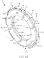
- Rotor core 49 may comprise a rotor spine 110 and rotor lugs 46. Rotor core 49 may engage rotor splines 18 ( FIG. 1 ) in rotor gaps 112 formed between rotor lugs 46. In this regard, rotor 42 may be rotatable by virtue of the engagement between rotor lugs 46 and rotor splines 18 of wheel 10 ( FIG. 1 ). Rotor core 49 further comprises a first surface 106 and a second surface 108 opposite first surface 106. First surface 106 and second surface 108 may extend along rotor spine 110 between an inner circumferential surface 102 and outer circumferential surface 104 of rotor core 49. A plurality of first depressions 120 may be formed in, and defined by, first surface 106.
- a plurality of second depressions 122 may be formed in, and defined by, second surface 108.
- First depressions 120 may be axially aligned with second depressions 122.
- First depressions 120 and second depressions 122 may each be formed partially through rotor core 49 such that a portion of rotor core 49 remains between a bottom, or axially inward, surface of first depressions 120 and a bottom, or axially inward, surface of second depressions 122.
- First depressions 120 and second depressions 122 may comprise a generally cylindrical or frustoconical shape.
- the shape of first depressions 120 and second depressions 122 may complement the shape of protrusions 160.
- An opening 166 may be formed through protrusions 160. Openings 166 may extend completely through wear liners 50 such that openings 166 extend from wear surface 156 to a surface 168 of protrusion 160 opposite wear surface 156.
- An opening 116 may be formed through first depressions 120 and second depressions 122. Openings 116 may extend completely through rotor core 49. With momentary reference to FIG. 2C , openings 116 may extend from the bottom, or axially inward, surface 130 of first depressions 120 to the bottom, or axially inward, surface 132 of second depressions 122. Openings 116 may be aligned with openings 166 and may be configured to receive a fastener for securing wear liners 50 to rotor core 49.
- protrusions 160 may be located and/or positioned within first depressions 120 and second depressions 122.
- the protrusions 160 adjacent to first surface 106 of rotor core 49 may be positioned within first depressions 120, and the protrusions 160 adjacent to second surface 108 of rotor core 49 may be positioned with second depressions 122.
- Fasteners 170 may couple or otherwise secure wear liners 50 to rotor core 49.
- Fasteners 170 may comprise a rivet, bolt, pin, screw, or other suitable securement mechanism. Fasteners 170 may be located through protrusions 160.
- Fasteners 170 extend between opposing wear liner segments.
- fastener 170a extends between opposing wear liner segments 150a.
- Fastener 170b extends between opposing wear liner segments 150b.
- Fastener 170c extends between opposing wear liner segments 150c.
- fasteners 170 may couple wear liner segments 150a, 150b, and 150c to rotor core 49.
- Openings 166 may include a counterbore configured to receive fastener 170.
- Heads 172 of fasteners 170 may be recessed with respect to wear surface 156. Locating fasteners 170 through protrusion 160 may allow the heads 172 of fasteners 170 to be located a greater distance from wear surface 156.
- heads 172 of fasteners 170 may remain recessed with respect to wear surface 156.
- Stator 40 may comprise a stator core 48 and wear liners 50.
- Stator core 48 may comprise stator lugs 44.
- Stator lugs 44 may be located along an inner circumferential surface 202.
- Stator gaps 210 may be located between stator lugs 44.
- Stator gaps 210 may be positioned to align with stator splines 36 ( FIG. 1 ). The engagement between the stator splines 36 and stator lugs 44 may prevent stator core 48 from rotating in response to a torque being applied to stator 40 during braking.
- Stator core 48 may include opposing first and second surfaces extending between inner circumferential surface 202 and an outer circumferential surface 204.
- a plurality of first depressions 220 may be formed in the first surface of stator core 48.
- a plurality of second depressions 222 may be formed in the second surface of stator core 48.
- First depressions 220 may axially aligned with second depressions 222.
- First depressions 220 and second depressions 222 may each be formed partially through stator core 48 such that a portion of stator core 48 remains between a bottom, or axially inward, surface of first depressions 220 and a bottom, or axially inward, surface of second depressions 222.
- Protrusions 160 may be located and/or positioned in first depressions 220 and second depressions 222.
- Wear liners 50 including wear liner segments 150a, 150b, and 150c, may be coupled to stator core 48 with wear surface 156 oriented away from stator core 48 and protrusions 160 oriented toward stator core 48.
- Fasteners 270 similar to fasteners 170 in FIG. 2B , may be located through protrusion 160 and may couple wear liner segments 150a, 150b, and 150c to stator core 48.
- wear liner segments 150a, 150b, and 150c may have an identical or substantially similar configuration.
- the configuration of depressions 120, 122 in rotor core 49 may be identical or substantially similar to the configuration of depressions 220, 222 in stator core 48 such that wear liner segments 150a, 150b, and 150c may be compatible with both (i.e., interchangeable between) rotor core 49 and stator core 48.
- wear liners 50 may be replaceable, such that after wear liners 50 have been worn below a suitable operational thickness, wear liners 50 may be removed from rotor core 49 and/or stator core 48 and replaced with new or remanufactured wear liners 50.
- Wear liners 50 formed from a plurality of discrete segments tend to be less susceptible to warpage as compared to unibody wear liners of similar thickness. In this regard, wear liners 50 being segmented may allow a greater volume of wear liners 50 to be consumed (i.e. used, worn) prior to replacement.
- Rotor 342 may comprise a rotor core 349, and rotor wear liners 350 (one shown) disposed over opposing surfaces of rotor core 349.
- Rotor core 349 may comprise a rotor spine 310 and rotor lugs 346.
- Rotor 342 may engage rotor splines 18 ( FIG. 1 ) in rotor gaps 320 formed between rotor lugs 346.
- Rotor 342 may be rotatable by virtue of the engagement between rotor lugs 346 and rotor splines 18 of wheel 10, with momentary reference to FIG. 1 .
- Rotor core 349 comprises an inner circumferential surface 302 and an outer circumferential surface 304.
- Rotor lugs 346 may be located along outer circumferential surface 304.
- Rotor core 349 further comprises opposing sides 306 and 308, which extend from inner circumferential surface 302 to outer circumferential surface 304.
- Rotor core 349 may further comprise rotor core key notches 341.
- Rotor core key notches 341 may be a recessed portion of rotor lugs 346 such that rotor lugs 346 have a decreased thickness at rotor core key notches 341.
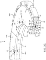
- Wear liner 350 may be segmented such that wear liner 350 comprises a plurality of wear liner segments (e.g., first wear liner segment 350a, second wear liner segment 350b, and third wear liner segment 350c). Wear liner segments 350a, 350b, and 350c may jointly form a generally annular or ring-shaped structure (i.e., wear liner 350). Stated differently, wear liner 350 may be constructed from multiple arcuate segments that together extend substantially 360 degrees around an axis 321. As used herein, “substantially 360 degrees” means within 5 degrees of 360 degrees. While wear liner 350 is shown including three wear liner segments (350a, 350b, and 350c), it should be understood that wear liner 350 may comprise any number of wear liner segments.
- Wear liner 350 comprises an inner circumferential surface 352 and an outer circumferential surface 354. Wear liner 350, including wear liner segments 350a, 350b, and 350c, further comprises a wear surface 356 and a non-wear surface 358 opposite wear surface 156. Wear surface 356 is oriented away from rotor core 349. Non-wear surface 358 is oriented toward rotor core 349.
- wear liner segments 350a, 350b, and 350c each include at least one rotor key (flange) 345. Flanges 345 may be located along and extend radially outward from outer circumferential surface 354. Flanges 345 may be sized and shaped to fit into rotor core key notches 341.
- Rotor wear liners 350 including wear liner segments 350a, 350b, and 350c, may be coupled to opposing sides 306 and side 308, with momentary reference to FIG. 4A , of a rotor core 349.
- rotor wear liners 350 including wear liner segments 350a, 350b, and 350c, may be coupled to rotor core 349 by a plurality of fasteners 370 and cover plates 372.
- Fasteners 370 may comprise rivets, clips, screws, bolts, or other suitable securement mechanism.
- fasteners 370 may extend through cover plates 372, flanges 345, and rotor lugs 346.
- rotor wear liners 350 including wear liner segments 350a, 350b, and 350c, may be bonded to rotor core 349.
- rotor wear liners 350, including wear liner segments 350a, 350b, and 350c may be floating, such that wear liner segments 350a, 350b, and 350c are positioned adjacent to rotor core 349 without being fastened thereto.
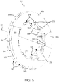
- Stator 340 may comprise a stator core 348 and stator wear liners 360 located over opposing sides of stator core 348.
- Stator core 348 may comprise stator lugs 344 located along and extending radially inward from an inner circumferential surface 322 of stator core 348.
- Gaps 333 may be located between stator lugs 344.
- Gaps 333 may be configured to align with stator splines 36 ( FIG. 1 ). The engagement between the stator splines 36 and stator lugs 344 may prevent stator 340 from rotating when a torque is applied to stator 340 during braking.
- Stator core 348 may further comprise core keys 374 and core key notches 376 located proximate inner circumferential surface 322 of stator core 348.
- Core keys 374 may comprise radially outward extending teeth.
- Core key notches 376 may be radially inward extending recesses located between core keys 374.
- Wear liners 360 may be segmented such that each wear liner 360 comprises a plurality of wear liner segments (e.g., first wear liner segment 360a, second wear liner segment 360b, and third wear liner segment 360c). Wear liner segments 360a, 360b, and 360c may jointly form an annular or ring-shaped structure (i.e., wear liner 360). Stated differently, wear liners 360 may be constructed from multiple arcuate segments that together extend substantially 360 degrees around axis 321. As used herein, "substantially 360 degrees” means within 5 degrees of 360 degrees. While wear liners 360 are shown including three wear liner segments (360a, 360b, and 360c), it should be understood that wear liners 360 may comprise any number of wear liner segments.
- Wear liners 360 comprising wear liner segments 360a, 360b, and 360c, comprise an inner circumferential surface 382 and an outer circumferential surface 384. Wear liners 360, including wear liner segments 360a, 360b, and 360c, further comprise a wear surface 396 and a non-wear surface opposite wear surface 396. Wear surface 396 is oriented away from stator core 348.
- wear liner segments 360a, 360b, and 360c each include at least one stator key (flange) 359.
- Flanges 359 may be located along and extend radially inward from inner circumferential surface 382.
- Flanges 359 may be sized and shaped to fit into core key notches 376.
- stator core keys 374 may be sized and shaped to fit in between flanges 359.
- Wear liners 360 may be coupled to stator core 348 by, for example, a bond.
- a bond may comprise an adhesive capable of maintaining adhesion under high temperatures, for example, between about 426° C (about 800° F) and 1093° C (about 2000° F).
- an adhesive may be applied via chemical vapor deposition.
- wear liners 360 may be coupled to stator core 348 by mechanical fastening through flanges 359.
- wear liners 360 may be coupled to stator core 348 via rivets, clips, bolts, or other suitable fastener secured to flanges 359.
- wear liners 360 are kept in place by contact from adjacent components, such as wear liners 350 attached to rotor 342, with momentary reference to FIG. 4B .
- wear liners 350 and 360 may be replaceable, such that after wear liners 350 and/or 360 have been worn below a suitable operational thickness, wear liners 350 and/or 360 may be removed from rotor core 349 and/or stator core 348, respectively, and replaced with new or remanufactured wear liners.
- Wear liners 350 and 360 being formed from a plurality of discrete segments tend to be less susceptible to warpage as compared to unibody wear liners of similar thickness. In this regard, wear liners 350 and 360 being segmented may allow a greater volume of the wear liner to be consumed (i.e. used, worn) prior to replacement.
- references to "one embodiment”, “an embodiment”, “an example embodiment”, etc. indicate that the embodiment described may include a particular feature, structure, or characteristic, but every embodiment may not necessarily include the particular feature, structure, or characteristic. Moreover, such phrases are not necessarily referring to the same embodiment. Further, when a particular feature, structure, or characteristic is described in connection with an embodiment, it is submitted that it is within the knowledge of one skilled in the art to affect such feature, structure, or characteristic in connection with other embodiments whether or not explicitly described. After reading the description, it will be apparent to one skilled in the relevant art(s) how to implement the disclosure in alternative embodiments.
Landscapes
- Engineering & Computer Science (AREA)
- General Engineering & Computer Science (AREA)
- Mechanical Engineering (AREA)
- Braking Arrangements (AREA)
Applications Claiming Priority (1)
| Application Number | Priority Date | Filing Date | Title |
|---|---|---|---|
| US15/822,365 US10941823B2 (en) | 2017-11-27 | 2017-11-27 | Segmented wear liner |
Publications (2)
| Publication Number | Publication Date |
|---|---|
| EP3489538A1 true EP3489538A1 (de) | 2019-05-29 |
| EP3489538B1 EP3489538B1 (de) | 2021-03-24 |
Family
ID=64556668
Family Applications (1)
| Application Number | Title | Priority Date | Filing Date |
|---|---|---|---|
| EP18208687.6A Active EP3489538B1 (de) | 2017-11-27 | 2018-11-27 | Segmentierter verschleissschutz |
Country Status (2)
| Country | Link |
|---|---|
| US (1) | US10941823B2 (de) |
| EP (1) | EP3489538B1 (de) |
Cited By (5)
| Publication number | Priority date | Publication date | Assignee | Title |
|---|---|---|---|---|
| CN110561184A (zh) * | 2019-09-17 | 2019-12-13 | 浙江合奥机械科技有限公司 | 一种数控机床的制动装置 |
| CN111396478A (zh) * | 2020-06-09 | 2020-07-10 | 莱州伟辰汽车配件有限公司 | 一种可快速散热的双片筋条刹车盘 |
| EP3825570A1 (de) * | 2019-11-21 | 2021-05-26 | Honeywell International Inc. | Bremsscheibenanordnung |
| US11125289B2 (en) | 2019-07-03 | 2021-09-21 | Honeywell International Inc. | Brake disc assembly |
| CN117646769A (zh) * | 2024-01-29 | 2024-03-05 | 临汾市埠瑞联特煤机有限公司 | 一种气动履带平板车常闭式制动器 |
Families Citing this family (6)
| Publication number | Priority date | Publication date | Assignee | Title |
|---|---|---|---|---|
| US11614136B2 (en) | 2020-01-14 | 2023-03-28 | Goodrich Corporation | Wear liner manufacturing systems and methods |
| US11834159B2 (en) | 2021-10-18 | 2023-12-05 | Goodrich Corporation | Torque button bushing |
| US12331801B2 (en) * | 2022-05-24 | 2025-06-17 | Goodrich Corporation | Stator clip for brake assembly |
| US12385537B2 (en) | 2022-05-24 | 2025-08-12 | Goodrich Corporation | Stator clip for brake assembly |
| EP4293246B1 (de) * | 2022-06-13 | 2025-02-19 | Goodrich Corporation | Rotorclip für bremsenanordnung |
| US20250154997A1 (en) * | 2023-11-10 | 2025-05-15 | Goodrich Corporation | Washer for improved riveting of carbon wear liners to ceramic matrix composite (cmc) cores |
Citations (4)
| Publication number | Priority date | Publication date | Assignee | Title |
|---|---|---|---|---|
| US3731769A (en) * | 1971-10-13 | 1973-05-08 | Goodrich Co B F | Friction member assembly |
| US3857469A (en) * | 1971-11-04 | 1974-12-31 | Dunlop Ltd | Improvements in composite articles |
| GB2488654A (en) * | 2011-03-01 | 2012-09-05 | Geoffrey K Mccord | Segmented brake rotor with externally vented carrier |
| US9194447B2 (en) * | 2013-11-11 | 2015-11-24 | Goodrich Corporation | Keyed brake disk assembly |
Family Cites Families (41)
| Publication number | Priority date | Publication date | Assignee | Title |
|---|---|---|---|---|
| US3708042A (en) | 1970-09-21 | 1973-01-02 | Bendix Corp | Carbon core segmented friction disc |
| US3800392A (en) | 1970-11-05 | 1974-04-02 | Goodyear Tire & Rubber | Graphite and/or carbon disk with removable wear faces |
| US3747712A (en) | 1971-09-20 | 1973-07-24 | Bendix Corp | Friction disc for disc brake |
| US3951240A (en) | 1971-10-07 | 1976-04-20 | Dunlop Limited | Frictional disc arrangement for a disc brake |
| US3710914A (en) | 1971-12-18 | 1973-01-16 | Friction Prod Co | Rivetless friction pad for aircraft brakes |
| GB1446312A (en) | 1972-12-21 | 1976-08-18 | Dunlop Ltd | Disc brakes |
| US3927740A (en) | 1974-07-01 | 1975-12-23 | Goodyear Aerospace Corp | Brake disk with tapered key way |
| US3966029A (en) | 1974-11-29 | 1976-06-29 | Spain Raymond G | Two piece brake disc |
| SU703046A4 (ru) | 1975-04-18 | 1979-12-05 | С.А.Мессье (Фирма) | Дисковый тормоз |
| US4007814A (en) | 1976-02-05 | 1977-02-15 | Goodyear Aerospace Corporation | Carbon brake disk with cast keyslot reinforcement members |
| US4076106A (en) | 1976-10-19 | 1978-02-28 | Goodyear Aerospace Corporation | Snap fasteners for brake disk wear plates |
| US4214651A (en) | 1978-11-06 | 1980-07-29 | The Bendix Corporation | Friction disc for an aircraft brake |
| US4276969A (en) | 1979-04-02 | 1981-07-07 | Goodyear Aerospace Corporation | Method and means for fastening friction wear pads |
| GB8428953D0 (en) | 1984-11-16 | 1984-12-27 | Dunlop Ltd | Bonding of carbon-based components |
| US4982818A (en) | 1989-10-17 | 1991-01-08 | Allied-Signal Inc. | Cyclic brake disc overhaul technique and structure |
| US5099960A (en) | 1990-07-27 | 1992-03-31 | Aircraft Braking Systems Corp. | Composite brake disk and method of extending the braking service life thereof |
| US5779006A (en) | 1995-05-24 | 1998-07-14 | The B. F. Goodrich Company | Composite friction disk having replaceable wear faces |
| US5558186A (en) * | 1995-05-24 | 1996-09-24 | The Bfgoodrich Company | Friction disk with renewable wear faces |
| US5769185A (en) | 1995-05-25 | 1998-06-23 | Aircraft Braking Systems Corporation | Carbon brake disc structures and method of making same |
| FR2755094B1 (fr) | 1996-10-31 | 1998-11-27 | Messier Bugatti | Agencement de disques de frein en carbone pour unite de freinage d'aeronef, et procede d'assemblage de disques selon un tel agencement |
| FR2786239B1 (fr) | 1998-11-25 | 2001-02-16 | Messier Bugatti | Dispositif de friction a disques a commande pneumatique pour transmission |
| DE10000915C2 (de) | 2000-01-12 | 2002-11-07 | Daimler Chrysler Ag | Bremsvorrichtung für ein Fahrzeug |
| US7090057B2 (en) * | 2001-06-04 | 2006-08-15 | Honeywell International Inc. | Composite friction disc with structural core and refurbishable lining elements |
| DE10157483C2 (de) | 2001-11-23 | 2003-10-16 | Sgl Carbon Ag | Formkörper aus faserverstärkten Verbundwerkstoffen mit segmentierter Deckschicht, seine Herstellung und seine Verwendung |
| GB2403989B (en) | 2003-07-15 | 2006-06-14 | Dunlop Aerospace Ltd | Composite article |
| US7900751B2 (en) | 2006-02-01 | 2011-03-08 | Honeywell International Inc. | Method and brake disc assembly to utilize worn refurbished brake material |
| US20070193836A1 (en) | 2006-02-23 | 2007-08-23 | Walker Terence B | Method and brake disc with composite insert member |
| US7543691B2 (en) * | 2006-07-12 | 2009-06-09 | Delphi Technologies, Inc. | Brake rotor assembly |
| US20080041674A1 (en) | 2006-08-18 | 2008-02-21 | Honeywell International Inc. | Carbon-carbon stator insert for aircraft brakes |
| US8573369B2 (en) | 2006-12-07 | 2013-11-05 | Honeywell International Inc. | Methods and brake disc assemblies to increase the use of friction material |
| US20100025164A1 (en) | 2007-02-02 | 2010-02-04 | Honeywell International Inc. | Aircraft brake assembly having steel-backed carbon pressure plate |
| US7802758B2 (en) | 2007-05-04 | 2010-09-28 | Honeywell International Inc. | Load-distributing rotor insert for aircraft brakes |
| US7766133B2 (en) | 2007-06-04 | 2010-08-03 | Honeywell International, Inc. | Insert and retainer for securing same to an aircraft brake disk |
| US8281907B2 (en) * | 2007-12-03 | 2012-10-09 | Honeywell International Inc. | Brake assembly having multi-piece core and replaceable friction surfaces |
| US8789665B2 (en) | 2008-09-18 | 2014-07-29 | Carlisle Brake & Friction, Inc. | Carbon fiber reinforced carbon matrix composite for brake pad back plate |
| US10040543B2 (en) | 2010-03-12 | 2018-08-07 | Goodrich Corporation | Tapered brake disk |
| US20110272222A1 (en) | 2010-05-07 | 2011-11-10 | Brake Parts, Inc. | Hybrid brake pad |
| US9315261B2 (en) * | 2013-06-26 | 2016-04-19 | Goodrich Corporation | Keyed brake disk assembly |
| US9587691B2 (en) * | 2015-01-27 | 2017-03-07 | Goodrich Corporation | Friction disks with floating wear linings |
| US9366302B1 (en) * | 2015-01-30 | 2016-06-14 | Goodrich Corporation | Friction disks with floating wear linings |
| US10274034B2 (en) * | 2017-07-12 | 2019-04-30 | Goodrich Corporation | Wear liner with integrated torque button |
-
2017
- 2017-11-27 US US15/822,365 patent/US10941823B2/en active Active
-
2018
- 2018-11-27 EP EP18208687.6A patent/EP3489538B1/de active Active
Patent Citations (4)
| Publication number | Priority date | Publication date | Assignee | Title |
|---|---|---|---|---|
| US3731769A (en) * | 1971-10-13 | 1973-05-08 | Goodrich Co B F | Friction member assembly |
| US3857469A (en) * | 1971-11-04 | 1974-12-31 | Dunlop Ltd | Improvements in composite articles |
| GB2488654A (en) * | 2011-03-01 | 2012-09-05 | Geoffrey K Mccord | Segmented brake rotor with externally vented carrier |
| US9194447B2 (en) * | 2013-11-11 | 2015-11-24 | Goodrich Corporation | Keyed brake disk assembly |
Cited By (10)
| Publication number | Priority date | Publication date | Assignee | Title |
|---|---|---|---|---|
| US11125289B2 (en) | 2019-07-03 | 2021-09-21 | Honeywell International Inc. | Brake disc assembly |
| US11746843B2 (en) | 2019-07-03 | 2023-09-05 | Honeywell International Inc. | Brake disc assembly |
| CN110561184A (zh) * | 2019-09-17 | 2019-12-13 | 浙江合奥机械科技有限公司 | 一种数控机床的制动装置 |
| CN110561184B (zh) * | 2019-09-17 | 2021-04-20 | 浙江合奥机械科技有限公司 | 一种数控机床的制动装置 |
| EP3825570A1 (de) * | 2019-11-21 | 2021-05-26 | Honeywell International Inc. | Bremsscheibenanordnung |
| US11384805B2 (en) | 2019-11-21 | 2022-07-12 | Honeywell International Inc. | Brake disc assembly |
| CN111396478A (zh) * | 2020-06-09 | 2020-07-10 | 莱州伟辰汽车配件有限公司 | 一种可快速散热的双片筋条刹车盘 |
| CN111396478B (zh) * | 2020-06-09 | 2020-09-11 | 莱州伟辰汽车配件有限公司 | 一种可快速散热的双片筋条刹车盘 |
| CN117646769A (zh) * | 2024-01-29 | 2024-03-05 | 临汾市埠瑞联特煤机有限公司 | 一种气动履带平板车常闭式制动器 |
| CN117646769B (zh) * | 2024-01-29 | 2024-04-12 | 临汾市埠瑞联特煤机有限公司 | 一种气动履带平板车常闭式制动器 |
Also Published As
| Publication number | Publication date |
|---|---|
| US20190162260A1 (en) | 2019-05-30 |
| US10941823B2 (en) | 2021-03-09 |
| EP3489538B1 (de) | 2021-03-24 |
Similar Documents
| Publication | Publication Date | Title |
|---|---|---|
| EP3489538B1 (de) | Segmentierter verschleissschutz | |
| EP3428470B1 (de) | Verschleissschutz mit integriertem drehmomentknopf | |
| US9541145B2 (en) | Keyed brake disk assembly | |
| US9194447B2 (en) | Keyed brake disk assembly | |
| US9366302B1 (en) | Friction disks with floating wear linings | |
| EP3187746A1 (de) | Plattenanordnungen mit schwimmenden verschleissverkleidungen für mehrscheibenbremssystem und verfahren zur verringerung der vibrationen in einem mehrscheibenbremssystem | |
| EP3051166B1 (de) | Reibscheiben mit schwimmenden verschleissauskleidungen | |
| EP3418601B1 (de) | Lamellenbremsanordnung mit hubbegrenzungsstift | |
| EP3712458B1 (de) | Verschleissauskleidung mit unidirektionaler kerbe | |
| EP3708861B1 (de) | Segmentierter integrierter schlitzschleissrücken mit strukturellem kohlenstoff- oder keramikkern | |
| EP3712457B1 (de) | Segmentierte nietlose verschleissauskleidung mit strukturellem kohlenstoff- oder keramikkern | |
| EP3690273A1 (de) | Schleissrücken mit integrierter drehmomentrippe | |
| EP3715663B1 (de) | Segmentierte nietlose verschleissauskleidung mit strukturellem kohlenstoff- oder keramikkern | |
| US20250154997A1 (en) | Washer for improved riveting of carbon wear liners to ceramic matrix composite (cmc) cores | |
| US20260009436A1 (en) | Attachment of carbon wear liners to ceramic matrix composite (cmc) cores |
Legal Events
| Date | Code | Title | Description |
|---|---|---|---|
| PUAI | Public reference made under article 153(3) epc to a published international application that has entered the european phase |
Free format text: ORIGINAL CODE: 0009012 |
|
| STAA | Information on the status of an ep patent application or granted ep patent |
Free format text: STATUS: THE APPLICATION HAS BEEN PUBLISHED |
|
| AK | Designated contracting states |
Kind code of ref document: A1 Designated state(s): AL AT BE BG CH CY CZ DE DK EE ES FI FR GB GR HR HU IE IS IT LI LT LU LV MC MK MT NL NO PL PT RO RS SE SI SK SM TR |
|
| AX | Request for extension of the european patent |
Extension state: BA ME |
|
| STAA | Information on the status of an ep patent application or granted ep patent |
Free format text: STATUS: REQUEST FOR EXAMINATION WAS MADE |
|
| 17P | Request for examination filed |
Effective date: 20191129 |
|
| RBV | Designated contracting states (corrected) |
Designated state(s): AL AT BE BG CH CY CZ DE DK EE ES FI FR GB GR HR HU IE IS IT LI LT LU LV MC MK MT NL NO PL PT RO RS SE SI SK SM TR |
|
| STAA | Information on the status of an ep patent application or granted ep patent |
Free format text: STATUS: EXAMINATION IS IN PROGRESS |
|
| 17Q | First examination report despatched |
Effective date: 20200327 |
|
| GRAP | Despatch of communication of intention to grant a patent |
Free format text: ORIGINAL CODE: EPIDOSNIGR1 |
|
| STAA | Information on the status of an ep patent application or granted ep patent |
Free format text: STATUS: GRANT OF PATENT IS INTENDED |
|
| INTG | Intention to grant announced |
Effective date: 20201022 |
|
| GRAS | Grant fee paid |
Free format text: ORIGINAL CODE: EPIDOSNIGR3 |
|
| GRAA | (expected) grant |
Free format text: ORIGINAL CODE: 0009210 |
|
| STAA | Information on the status of an ep patent application or granted ep patent |
Free format text: STATUS: THE PATENT HAS BEEN GRANTED |
|
| AK | Designated contracting states |
Kind code of ref document: B1 Designated state(s): AL AT BE BG CH CY CZ DE DK EE ES FI FR GB GR HR HU IE IS IT LI LT LU LV MC MK MT NL NO PL PT RO RS SE SI SK SM TR |
|
| REG | Reference to a national code |
Ref country code: GB Ref legal event code: FG4D |
|
| REG | Reference to a national code |
Ref country code: CH Ref legal event code: EP |
|
| REG | Reference to a national code |
Ref country code: IE Ref legal event code: FG4D |
|
| REG | Reference to a national code |
Ref country code: AT Ref legal event code: REF Ref document number: 1374784 Country of ref document: AT Kind code of ref document: T Effective date: 20210415 Ref country code: DE Ref legal event code: R096 Ref document number: 602018014326 Country of ref document: DE |
|
| REG | Reference to a national code |
Ref country code: LT Ref legal event code: MG9D |
|
| PG25 | Lapsed in a contracting state [announced via postgrant information from national office to epo] |
Ref country code: NO Free format text: LAPSE BECAUSE OF FAILURE TO SUBMIT A TRANSLATION OF THE DESCRIPTION OR TO PAY THE FEE WITHIN THE PRESCRIBED TIME-LIMIT Effective date: 20210624 Ref country code: BG Free format text: LAPSE BECAUSE OF FAILURE TO SUBMIT A TRANSLATION OF THE DESCRIPTION OR TO PAY THE FEE WITHIN THE PRESCRIBED TIME-LIMIT Effective date: 20210624 Ref country code: GR Free format text: LAPSE BECAUSE OF FAILURE TO SUBMIT A TRANSLATION OF THE DESCRIPTION OR TO PAY THE FEE WITHIN THE PRESCRIBED TIME-LIMIT Effective date: 20210625 Ref country code: HR Free format text: LAPSE BECAUSE OF FAILURE TO SUBMIT A TRANSLATION OF THE DESCRIPTION OR TO PAY THE FEE WITHIN THE PRESCRIBED TIME-LIMIT Effective date: 20210324 Ref country code: FI Free format text: LAPSE BECAUSE OF FAILURE TO SUBMIT A TRANSLATION OF THE DESCRIPTION OR TO PAY THE FEE WITHIN THE PRESCRIBED TIME-LIMIT Effective date: 20210324 |
|
| PG25 | Lapsed in a contracting state [announced via postgrant information from national office to epo] |
Ref country code: SE Free format text: LAPSE BECAUSE OF FAILURE TO SUBMIT A TRANSLATION OF THE DESCRIPTION OR TO PAY THE FEE WITHIN THE PRESCRIBED TIME-LIMIT Effective date: 20210324 Ref country code: RS Free format text: LAPSE BECAUSE OF FAILURE TO SUBMIT A TRANSLATION OF THE DESCRIPTION OR TO PAY THE FEE WITHIN THE PRESCRIBED TIME-LIMIT Effective date: 20210324 Ref country code: LV Free format text: LAPSE BECAUSE OF FAILURE TO SUBMIT A TRANSLATION OF THE DESCRIPTION OR TO PAY THE FEE WITHIN THE PRESCRIBED TIME-LIMIT Effective date: 20210324 |
|
| REG | Reference to a national code |
Ref country code: NL Ref legal event code: MP Effective date: 20210324 |
|
| REG | Reference to a national code |
Ref country code: AT Ref legal event code: MK05 Ref document number: 1374784 Country of ref document: AT Kind code of ref document: T Effective date: 20210324 |
|
| PG25 | Lapsed in a contracting state [announced via postgrant information from national office to epo] |
Ref country code: NL Free format text: LAPSE BECAUSE OF FAILURE TO SUBMIT A TRANSLATION OF THE DESCRIPTION OR TO PAY THE FEE WITHIN THE PRESCRIBED TIME-LIMIT Effective date: 20210324 |
|
| PG25 | Lapsed in a contracting state [announced via postgrant information from national office to epo] |
Ref country code: AT Free format text: LAPSE BECAUSE OF FAILURE TO SUBMIT A TRANSLATION OF THE DESCRIPTION OR TO PAY THE FEE WITHIN THE PRESCRIBED TIME-LIMIT Effective date: 20210324 Ref country code: SM Free format text: LAPSE BECAUSE OF FAILURE TO SUBMIT A TRANSLATION OF THE DESCRIPTION OR TO PAY THE FEE WITHIN THE PRESCRIBED TIME-LIMIT Effective date: 20210324 Ref country code: LT Free format text: LAPSE BECAUSE OF FAILURE TO SUBMIT A TRANSLATION OF THE DESCRIPTION OR TO PAY THE FEE WITHIN THE PRESCRIBED TIME-LIMIT Effective date: 20210324 Ref country code: EE Free format text: LAPSE BECAUSE OF FAILURE TO SUBMIT A TRANSLATION OF THE DESCRIPTION OR TO PAY THE FEE WITHIN THE PRESCRIBED TIME-LIMIT Effective date: 20210324 Ref country code: CZ Free format text: LAPSE BECAUSE OF FAILURE TO SUBMIT A TRANSLATION OF THE DESCRIPTION OR TO PAY THE FEE WITHIN THE PRESCRIBED TIME-LIMIT Effective date: 20210324 |
|
| PG25 | Lapsed in a contracting state [announced via postgrant information from national office to epo] |
Ref country code: IS Free format text: LAPSE BECAUSE OF FAILURE TO SUBMIT A TRANSLATION OF THE DESCRIPTION OR TO PAY THE FEE WITHIN THE PRESCRIBED TIME-LIMIT Effective date: 20210724 Ref country code: SK Free format text: LAPSE BECAUSE OF FAILURE TO SUBMIT A TRANSLATION OF THE DESCRIPTION OR TO PAY THE FEE WITHIN THE PRESCRIBED TIME-LIMIT Effective date: 20210324 Ref country code: RO Free format text: LAPSE BECAUSE OF FAILURE TO SUBMIT A TRANSLATION OF THE DESCRIPTION OR TO PAY THE FEE WITHIN THE PRESCRIBED TIME-LIMIT Effective date: 20210324 Ref country code: PT Free format text: LAPSE BECAUSE OF FAILURE TO SUBMIT A TRANSLATION OF THE DESCRIPTION OR TO PAY THE FEE WITHIN THE PRESCRIBED TIME-LIMIT Effective date: 20210726 Ref country code: PL Free format text: LAPSE BECAUSE OF FAILURE TO SUBMIT A TRANSLATION OF THE DESCRIPTION OR TO PAY THE FEE WITHIN THE PRESCRIBED TIME-LIMIT Effective date: 20210324 |
|
| REG | Reference to a national code |
Ref country code: DE Ref legal event code: R097 Ref document number: 602018014326 Country of ref document: DE |
|
| PG25 | Lapsed in a contracting state [announced via postgrant information from national office to epo] |
Ref country code: ES Free format text: LAPSE BECAUSE OF FAILURE TO SUBMIT A TRANSLATION OF THE DESCRIPTION OR TO PAY THE FEE WITHIN THE PRESCRIBED TIME-LIMIT Effective date: 20210324 Ref country code: DK Free format text: LAPSE BECAUSE OF FAILURE TO SUBMIT A TRANSLATION OF THE DESCRIPTION OR TO PAY THE FEE WITHIN THE PRESCRIBED TIME-LIMIT Effective date: 20210324 Ref country code: AL Free format text: LAPSE BECAUSE OF FAILURE TO SUBMIT A TRANSLATION OF THE DESCRIPTION OR TO PAY THE FEE WITHIN THE PRESCRIBED TIME-LIMIT Effective date: 20210324 |
|
| PLBE | No opposition filed within time limit |
Free format text: ORIGINAL CODE: 0009261 |
|
| STAA | Information on the status of an ep patent application or granted ep patent |
Free format text: STATUS: NO OPPOSITION FILED WITHIN TIME LIMIT |
|
| PG25 | Lapsed in a contracting state [announced via postgrant information from national office to epo] |
Ref country code: SI Free format text: LAPSE BECAUSE OF FAILURE TO SUBMIT A TRANSLATION OF THE DESCRIPTION OR TO PAY THE FEE WITHIN THE PRESCRIBED TIME-LIMIT Effective date: 20210324 |
|
| 26N | No opposition filed |
Effective date: 20220104 |
|
| PG25 | Lapsed in a contracting state [announced via postgrant information from national office to epo] |
Ref country code: IS Free format text: LAPSE BECAUSE OF FAILURE TO SUBMIT A TRANSLATION OF THE DESCRIPTION OR TO PAY THE FEE WITHIN THE PRESCRIBED TIME-LIMIT Effective date: 20210724 |
|
| REG | Reference to a national code |
Ref country code: DE Ref legal event code: R119 Ref document number: 602018014326 Country of ref document: DE |
|
| PG25 | Lapsed in a contracting state [announced via postgrant information from national office to epo] |
Ref country code: MC Free format text: LAPSE BECAUSE OF FAILURE TO SUBMIT A TRANSLATION OF THE DESCRIPTION OR TO PAY THE FEE WITHIN THE PRESCRIBED TIME-LIMIT Effective date: 20210324 |
|
| REG | Reference to a national code |
Ref country code: CH Ref legal event code: PL |
|
| PG25 | Lapsed in a contracting state [announced via postgrant information from national office to epo] |
Ref country code: BE Free format text: LAPSE BECAUSE OF NON-PAYMENT OF DUE FEES Effective date: 20211130 Ref country code: LU Free format text: LAPSE BECAUSE OF NON-PAYMENT OF DUE FEES Effective date: 20211127 |
|
| REG | Reference to a national code |
Ref country code: BE Ref legal event code: MM Effective date: 20211130 |
|
| PG25 | Lapsed in a contracting state [announced via postgrant information from national office to epo] |
Ref country code: LI Free format text: LAPSE BECAUSE OF NON-PAYMENT OF DUE FEES Effective date: 20211130 Ref country code: CH Free format text: LAPSE BECAUSE OF NON-PAYMENT OF DUE FEES Effective date: 20211130 |
|
| PG25 | Lapsed in a contracting state [announced via postgrant information from national office to epo] |
Ref country code: IE Free format text: LAPSE BECAUSE OF NON-PAYMENT OF DUE FEES Effective date: 20211127 Ref country code: DE Free format text: LAPSE BECAUSE OF NON-PAYMENT OF DUE FEES Effective date: 20220601 |
|
| PG25 | Lapsed in a contracting state [announced via postgrant information from national office to epo] |
Ref country code: IT Free format text: LAPSE BECAUSE OF FAILURE TO SUBMIT A TRANSLATION OF THE DESCRIPTION OR TO PAY THE FEE WITHIN THE PRESCRIBED TIME-LIMIT Effective date: 20210324 |
|
| P01 | Opt-out of the competence of the unified patent court (upc) registered |
Effective date: 20230521 |
|
| PG25 | Lapsed in a contracting state [announced via postgrant information from national office to epo] |
Ref country code: CY Free format text: LAPSE BECAUSE OF FAILURE TO SUBMIT A TRANSLATION OF THE DESCRIPTION OR TO PAY THE FEE WITHIN THE PRESCRIBED TIME-LIMIT Effective date: 20210324 |
|
| PG25 | Lapsed in a contracting state [announced via postgrant information from national office to epo] |
Ref country code: HU Free format text: LAPSE BECAUSE OF FAILURE TO SUBMIT A TRANSLATION OF THE DESCRIPTION OR TO PAY THE FEE WITHIN THE PRESCRIBED TIME-LIMIT; INVALID AB INITIO Effective date: 20181127 |
|
| PG25 | Lapsed in a contracting state [announced via postgrant information from national office to epo] |
Ref country code: MK Free format text: LAPSE BECAUSE OF FAILURE TO SUBMIT A TRANSLATION OF THE DESCRIPTION OR TO PAY THE FEE WITHIN THE PRESCRIBED TIME-LIMIT Effective date: 20210324 |
|
| PG25 | Lapsed in a contracting state [announced via postgrant information from national office to epo] |
Ref country code: TR Free format text: LAPSE BECAUSE OF FAILURE TO SUBMIT A TRANSLATION OF THE DESCRIPTION OR TO PAY THE FEE WITHIN THE PRESCRIBED TIME-LIMIT Effective date: 20210324 |
|
| PG25 | Lapsed in a contracting state [announced via postgrant information from national office to epo] |
Ref country code: MT Free format text: LAPSE BECAUSE OF FAILURE TO SUBMIT A TRANSLATION OF THE DESCRIPTION OR TO PAY THE FEE WITHIN THE PRESCRIBED TIME-LIMIT Effective date: 20210324 |
|
| PGFP | Annual fee paid to national office [announced via postgrant information from national office to epo] |
Ref country code: GB Payment date: 20251023 Year of fee payment: 8 |
|
| PGFP | Annual fee paid to national office [announced via postgrant information from national office to epo] |
Ref country code: FR Payment date: 20251023 Year of fee payment: 8 |