EP3489484A1 - Electrically driven supercharger - Google Patents
Electrically driven supercharger Download PDFInfo
- Publication number
- EP3489484A1 EP3489484A1 EP17904301.3A EP17904301A EP3489484A1 EP 3489484 A1 EP3489484 A1 EP 3489484A1 EP 17904301 A EP17904301 A EP 17904301A EP 3489484 A1 EP3489484 A1 EP 3489484A1
- Authority
- EP
- European Patent Office
- Prior art keywords
- compressor impeller
- electric supercharger
- gap
- side casing
- rotational shaft
- Prior art date
- Legal status (The legal status is an assumption and is not a legal conclusion. Google has not performed a legal analysis and makes no representation as to the accuracy of the status listed.)
- Granted
Links
- 239000011247 coating layer Substances 0.000 claims description 27
- 238000004891 communication Methods 0.000 claims description 13
- 238000011144 upstream manufacturing Methods 0.000 claims description 11
- 230000007246 mechanism Effects 0.000 claims description 6
- 238000010586 diagram Methods 0.000 description 40
- 230000007423 decrease Effects 0.000 description 24
- 230000007257 malfunction Effects 0.000 description 9
- 238000011161 development Methods 0.000 description 7
- 230000001737 promoting effect Effects 0.000 description 6
- XLYOFNOQVPJJNP-UHFFFAOYSA-N water Substances O XLYOFNOQVPJJNP-UHFFFAOYSA-N 0.000 description 3
- 238000001816 cooling Methods 0.000 description 2
- 230000000694 effects Effects 0.000 description 2
- 230000004044 response Effects 0.000 description 2
- 239000000758 substrate Substances 0.000 description 2
- 238000009423 ventilation Methods 0.000 description 2
- 230000008878 coupling Effects 0.000 description 1
- 238000010168 coupling process Methods 0.000 description 1
- 238000005859 coupling reaction Methods 0.000 description 1
- 239000000428 dust Substances 0.000 description 1
- 239000000446 fuel Substances 0.000 description 1
- 239000004519 grease Substances 0.000 description 1
- 239000000314 lubricant Substances 0.000 description 1
- 238000005461 lubrication Methods 0.000 description 1
- 239000000463 material Substances 0.000 description 1
- 238000000034 method Methods 0.000 description 1
- 238000012986 modification Methods 0.000 description 1
- 230000004048 modification Effects 0.000 description 1
- 239000003921 oil Substances 0.000 description 1
- 230000002093 peripheral effect Effects 0.000 description 1
- 238000007789 sealing Methods 0.000 description 1
- 238000013519 translation Methods 0.000 description 1
Images


Classifications
-
- F—MECHANICAL ENGINEERING; LIGHTING; HEATING; WEAPONS; BLASTING
- F02—COMBUSTION ENGINES; HOT-GAS OR COMBUSTION-PRODUCT ENGINE PLANTS
- F02B—INTERNAL-COMBUSTION PISTON ENGINES; COMBUSTION ENGINES IN GENERAL
- F02B39/00—Component parts, details, or accessories relating to, driven charging or scavenging pumps, not provided for in groups F02B33/00 - F02B37/00
- F02B39/02—Drives of pumps; Varying pump drive gear ratio
- F02B39/08—Non-mechanical drives, e.g. fluid drives having variable gear ratio
- F02B39/10—Non-mechanical drives, e.g. fluid drives having variable gear ratio electric
-
- F—MECHANICAL ENGINEERING; LIGHTING; HEATING; WEAPONS; BLASTING
- F04—POSITIVE - DISPLACEMENT MACHINES FOR LIQUIDS; PUMPS FOR LIQUIDS OR ELASTIC FLUIDS
- F04D—NON-POSITIVE-DISPLACEMENT PUMPS
- F04D25/00—Pumping installations or systems
- F04D25/02—Units comprising pumps and their driving means
- F04D25/06—Units comprising pumps and their driving means the pump being electrically driven
-
- F—MECHANICAL ENGINEERING; LIGHTING; HEATING; WEAPONS; BLASTING
- F04—POSITIVE - DISPLACEMENT MACHINES FOR LIQUIDS; PUMPS FOR LIQUIDS OR ELASTIC FLUIDS
- F04D—NON-POSITIVE-DISPLACEMENT PUMPS
- F04D29/00—Details, component parts, or accessories
- F04D29/05—Shafts or bearings, or assemblies thereof, specially adapted for elastic fluid pumps
- F04D29/056—Bearings
-
- F—MECHANICAL ENGINEERING; LIGHTING; HEATING; WEAPONS; BLASTING
- F04—POSITIVE - DISPLACEMENT MACHINES FOR LIQUIDS; PUMPS FOR LIQUIDS OR ELASTIC FLUIDS
- F04D—NON-POSITIVE-DISPLACEMENT PUMPS
- F04D29/00—Details, component parts, or accessories
- F04D29/08—Sealings
- F04D29/10—Shaft sealings
- F04D29/102—Shaft sealings especially adapted for elastic fluid pumps
-
- F—MECHANICAL ENGINEERING; LIGHTING; HEATING; WEAPONS; BLASTING
- F04—POSITIVE - DISPLACEMENT MACHINES FOR LIQUIDS; PUMPS FOR LIQUIDS OR ELASTIC FLUIDS
- F04D—NON-POSITIVE-DISPLACEMENT PUMPS
- F04D29/00—Details, component parts, or accessories
- F04D29/08—Sealings
- F04D29/10—Shaft sealings
- F04D29/12—Shaft sealings using sealing-rings
- F04D29/122—Shaft sealings using sealing-rings especially adapted for elastic fluid pumps
-
- F—MECHANICAL ENGINEERING; LIGHTING; HEATING; WEAPONS; BLASTING
- F04—POSITIVE - DISPLACEMENT MACHINES FOR LIQUIDS; PUMPS FOR LIQUIDS OR ELASTIC FLUIDS
- F04D—NON-POSITIVE-DISPLACEMENT PUMPS
- F04D29/00—Details, component parts, or accessories
- F04D29/26—Rotors specially for elastic fluids
- F04D29/28—Rotors specially for elastic fluids for centrifugal or helico-centrifugal pumps for radial-flow or helico-centrifugal pumps
- F04D29/284—Rotors specially for elastic fluids for centrifugal or helico-centrifugal pumps for radial-flow or helico-centrifugal pumps for compressors
Definitions
- the present disclosure relates to an electric supercharger.
- an exhaust turbine is driven by exhaust gas discharged from the engine to coaxially drive a compressor disposed in an intake passage and compress intake gas supplied to engine, which is called "supercharging".
- turbo lag A known technique to make up for the response delay due to turbo lag is a two-stage supercharging system which includes a turbocharger driven by exhaust gas and an electric supercharger driven by an electric motor (see Patent Document 1).
- Patent Document 1 JP2015-537162A (translation of a PCT application)
- the compressor is driven by a motor, unlike a turbocharger.
- devices such as a motor and an inverter substrate are disposed behind the compressor (between the compressor impeller and the bearing).
- the leakage flow may affect devices such as the motor and the inverter substrate.
- An object of at least one embodiment of the present invention is to provide an electric supercharger capable of suppressing entry of a leakage flow to the bearing side via the gap between the back surface of the compressor impeller and the casing.
- an electric supercharger capable of suppressing entry of a leakage flow to the bearing side via the gap between the back surface of the compressor impeller and the casing.
- an expression of relative or absolute arrangement such as “in a direction”, “along a direction”, “parallel”, “orthogonal”, “centered”, “concentric” and “coaxial” shall not be construed as indicating only the arrangement in a strict literal sense, but also includes a state where the arrangement is relatively displaced by a tolerance, or by an angle or a distance whereby it is possible to achieve the same function.
- an expression of an equal state such as “same” “equal” and “uniform” shall not be construed as indicating only the state in which the feature is strictly equal, but also includes a state in which there is a tolerance or a difference that can still achieve the same function.
- an expression of a shape such as a rectangular shape or a cylindrical shape shall not be construed as only the geometrically strict shape, but also includes a shape with unevenness or chamfered corners within the range in which the same effect can be achieved.
- FIG. 1 is a schematic diagram showing a schematic cross-sectional view of an electric supercharger 2 according to an embodiment.
- the electric supercharger 2 includes a compressor impeller 4, a rotational shaft 6, an impeller casing 8, bearings 10A, 10B, a motor 12, a back-surface side casing 14 (stationary member), and a mechanical seal 20.
- circumferential direction of the compressor impeller 4 is referred to as merely “circumferential direction”
- radial direction of the compressor impeller 4 is referred to as merely “radial direction”
- axial direction of the compressor impeller 4 is referred to as merely “axial direction”.
- the impeller casing 8 is formed so as to surround the compressor impeller 4, and is configured to guide intake air to the inlet of the compressor impeller 4 and discharge air compressed by the compressor impeller 4.
- the bearings 10A, 10B are configured as ball bearings that support the rotational shaft 6 rotatably, and as grease-lubrication type bearings which contain grease as a lubricating agent sealed around balls held between an inner race and an outer race which are not depicted.
- the bearing 10A is positioned between the mechanical seal 20 and the motor 12 in the axial direction, and is positioned between the back-surface side casing 14 and the rotational shaft 6 in the radial direction.
- the bearing 10B is positioned opposite to the bearing 10A across the motor 12 in the axial direction, and is positioned between the back-surface side casing 14 and the rotational shaft 6 in the radial direction.
- the motor 12 is configured to transmit a driving force to the compressor impeller 4 via the rotational shaft 6.
- the motor 12 is positioned between the bearing 10A and the bearing 10B in the axial direction.
- the back-surface side casing 14 faces the back surface 16 of the compressor impeller 4 via a gap, and is configured to surround the mechanical seal 20, the bearings 10A, 10B, and the motor 12. Further, the back-surface side casing 14 includes an inverter housing portion 18 for housing an inverter (not depicted), on the opposite side from the motor 12 across the bearing 10B.
- the mechanical seal 20 is positioned between the back surface 16 of the compressor impeller 4 and the bearing 10A in the axial direction, and is configured to seal the gap between the rotational shaft 6 and the back-surface side casing 14.
- FIG. 2 is a schematic diagram showing a schematic cross-sectional view in the vicinity of a back surface 16 of a compressor impeller 4 of an electric supercharger 2 (2A) according to an embodiment, showing a configuration example of a mechanical seal 20.
- FIG. 3 is a view of a compressor impeller 4 in rotation, in the electric supercharger 2 (2A) depicted in FIG. 2 .
- the mechanical seal 20 includes a stationary ring 22, a rotary ring 24, and a biasing member 26.
- the stationary ring 22 is formed to have an annular shape along the circumferential direction, and is supported on the back-surface side casing 14.
- the stationary ring 22 is at a position that is between the rotary ring 24 and the back-surface side casing 14, and between the back-surface side casing 14 and the rotational shaft 6.
- the rotary ring 24 is disposed between the back surface 16 of the compressor impeller 4 and the stationary ring 22, and is configured to have an annular shape along the circumferential direction so as to face the stationary ring 22 so as to be capable of being in contact with the stationary ring 22.
- the rotary ring 24 is configured to protrude toward an outer side from the rotational shaft 6 in the radial direction, and rotate together with the rotational shaft 6.
- the biasing member 26 is configured to bias one of the stationary ring 22 or the rotary ring 24 toward the other one of the stationary ring 22 or the rotary ring 24.
- the biasing member 26 includes an elastic member (e.g., coil spring, disc spring, or rubber), and is interposed between the stationary ring 22 and the back-surface side casing 14 so as to bias the stationary ring 22 toward the rotary ring 24.
- a groove 34 is formed on a facing surface 32, which is one of a surface 28 of the rotary ring 24 that faces the stationary ring 22, or a surface 30 of the stationary ring 22 that faces the rotary ring 24 (in the depicted embodiment, the facing surface 32 is the surface 28 of the rotary ring 24 facing the stationary ring 22). As depicted in FIG.
- the groove 34 on the facing surface 32 is formed so as to be in communication with a space 36 on the inner side of the facing surface 32 in the radial direction (space between the stationary ring 22 and the rotational shaft 6), and so as not to be in communication with the space 38 on the outer side of the facing surface 32 in the radial direction (of the back-surface gap 'g' between the back surface 16 and the back-surface side casing 14, the outer portion of the stationary ring 22), in a state where the stationary ring 22 and the rotary ring 24 are in contact.
- the groove 34 is disposed from a position on the inner side, in the radially direction, of the radially inner end 40 of the contact portion between the stationary ring 22 and the rotary ring 24 on the facing surface 32 to a position that does not reach the radially outer end 42 of the contact portion between the stationary ring 22 and the rotary ring 24, on the facing surface 32.
- FIG. 4 is a schematic diagram showing a schematic cross-sectional view in the vicinity of a back surface 16 of a compressor impeller 4 of an electric supercharger 2 (2B) according to an embodiment.
- FIG. 5 is a diagram showing a configuration example of the ribs 44 depicted in FIG. 4 , showing an example of arrangement of the ribs 44 in an axial-directional view.
- FIG. 6 is a diagram showing a configuration example of the ribs 44 depicted in FIG. 4 , showing an example of arrangement of the ribs 44 in an axial-directional view.
- a plurality of ribs 44 are disposed at intervals in the circumferential direction, on the back surface 16 of the compressor 4.
- each of the ribs 44 is formed to extend along a direction that intersects with the circumferential direction. Further, in the embodiment depicted in FIG. 5 , the plurality of ribs 44 are disposed so as to extend in a radial fashion along a direction orthogonal to the circumferential direction (radial direction).
- the plurality of ribs 44 extending in a direction orthogonal to the circumferential direction rotates with the compressor impeller 4, and thus it is possible to apply the centrifugal force toward the outer side in the radial direction effectively to air in the back-surface gap 'g', and reduce the pressure of the radially inner part of the back-surface gap 'g'. Accordingly, it is possible to suppress entry of a leakage flow from the back-surface gap 'g' to the bearing 10A, and suppress inflow of the leakage flow into electric devices such as the motor.
- each of the ribs 44 has an airfoil shape.
- each rib 44 is disposed so as to extend in a direction inclined from the radial direction, such that the radially outer end 46 of the rib 44 is positioned on the upstream side of the radially inner end 48 of the rib 44, with respect to the rotational direction of the compressor impeller 4.
- FIG. 7 is a schematic diagram showing a schematic cross-sectional view in the vicinity of a back surface 16 of a compressor impeller 4 of an electric supercharger 2 (2C) according to an embodiment.
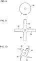
- FIG. 8 is a diagram showing a configuration example of the rotary part 50 depicted in FIG. 7 , showing an example of the shape of the rotary part 50 in an axial-directional view.
- FIG 9 is a diagram showing a configuration example of the rotary part 50 depicted in FIG. 7 , showing an example of the shape of the rotary part 50 in an axial-directional view.
- FIG. 10 is a diagram showing a configuration example of the rotary part 50 depicted in FIG. 7 , showing an example of the shape of the rotary part 50 in an axial-directional view.
- the electric supercharger further includes a rotary part 50 which protrudes outward in the radial direction from the rotational shaft 6, between the mechanical seal 20 and the back surface 16 of the compressor impeller 4, and which is configured to rotate together with the rotational shaft 6.
- the shape of the rotary part 50 is not particularly limited.
- the rotary part 51 may have an annular shape as depicted in FIG. 8 , or may have a plurality of protrusions 52 (four protrusions 52 in the depicted embodiment) protruding outward in the radial direction from the annular shape as depicted in FIGs. 9 and 10 .
- the protrusions 52 may protrude in a radial fashion along the radial direction as depicted in FIG. 9 for instance, or may have a tapered shape protruding diagonally with respect to the radial direction as depicted in FIG. 10 .
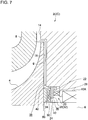
- FIG. 11 is a schematic diagram showing a schematic cross-sectional view in the vicinity of a back surface 16 of a compressor impeller 4 of an electric supercharger 2 (2D) according to an embodiment.
- FIG. 12 is a graph showing the relationship between the radial-directional position R and the gauge pressure P of the back-surface gap 'g'. The dotted line indicates an electric supercharger 2 (2A) not including an abradable coating layer 90, and the solid line indicates an electric supercharger 2 (2D) including an abradable coating layer 90 formed on the facing surface 21.
- FIG. 13 is a schematic diagram showing a schematic cross-sectional view in the vicinity of a back surface 16 of a compressor impeller 4 of an electric supercharger 2 (2E) according to an embodiment.
- an abradable coating layer 90 is formed on at least a part of the facing surface 21 facing the back surface 16 of the compressor impeller 4 (the entire facing surface 21 in the depicted embodiment).
- the abradable coating layer 90 would be ground upon rotation of the compressor impeller 4 even if the abradable coating layer 90 formed on the facing surface 21 makes contact with the back surface 16 of the compressor impeller 4.
- FIG. 12 is a graph schematically showing the relationship between the radial-directional position R and the gauge pressure P of the back-surface gap 'g'.
- the dotted line indicates an electric supercharger 2 (2A) not including an abradable coating layer 90
- the solid line indicates an electric supercharger 2 (2D) including an abradable coating layer 90 formed on the facing surface 21.
- the clearance C between the back surface 16 and the back-surface side casing 14 of the electric supercharger 2 (2D) is set to be smaller than the clearance between the back surface 16 and the back-surface side casing 14 of the electric supercharger 2 (2A).
- the electric supercharger 2 by promoting the pressure decrease toward the inner side in the radial direction in the back-surface gap 'g', it is possible to reduce the axial-directional pressure difference between the pressure of the radially inner part (pressure near the mechanical seal 20) of the back-surface gap 'g' and the pressure near the bearing 10A and thus it is possible to suppress entry of a leakage flow toward the bearing 10A (toward the mechanical seal 20) from the back-surface gap 'g'. Accordingly, it is possible to suppress inflow of the leakage flow into electric devices such as the motor 12 and an inverter (not depicted). Thus, it is possible to suppress occurrence of malfunction or the like of the electric devices, and operate the electric supercharger 2 stably.
- the compressor impeller 4 receives a thrust force toward the upstream in the intake direction of air (left side in the drawing), in the axial direction, when air is compressed.
- the above electric supercharger 2 it is possible to reduce the pressure in the back-surface gap 'g' for the compressor impeller 4, and thus it is possible to reduce the thrust force in the axial direction.
- the ratio C/Ri of the clearance C between the back surface 16 of the compressor impeller 4 and the back-surface side casing 14 to the outer diameter Ri of the compressor impeller 4 is less than 0.5%.
- the former when comparing a case where the abradable coating layer 90 is provided and the ratio C/Ri is set to be 0.8% and a case where the abradable coating layer 90 is not provided and C/Ri is set to be 0.25%, the former can reduce more pressure of the radially inner part of the back-surface gap 'g' by 26% compared to the latter.
- the abradable coating layer 90 is formed on at least a part of the back surface 16 of the compressor impeller 4. Furthermore, the ratio C/Ri of the clearance C between the back surface 16 of the compressor impeller 4 and the back-surface side casing 14 to the outer diameter Ri of the compressor impeller 4 is less than 0.5%.
- the abradable coating layer 90 would be ground upon rotation of the compressor impeller 4 even if the abradable coating layer 90 formed on the back surface 16 of the compressor impeller 4 makes contact with the facing surface 21 of the back-surface side casing 14.
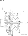
- the electric supercharger 2 (2A to 2E) further includes a communication hole 53 serving as an internal-pressure adjustment mechanism, configured to adjust the pressure inside the back-surface side casing 14 by bringing the inside and the outside of the back-surface side casing 14 into communication.
- the communication hole 53 may be disposed on the compressor side of the back-surface side casing 14 as depicted in FIG. 14 , or on the inverter side as depicted in FIG. 15 , or on both sides.
- the position, shape, and dimension like hole diameter of the communication hole 53 are to be designed to be optimum in accordance with the size of the electric supercharger 2. Further, in the embodiment depicted in FIGs.
- a waterproof ventilation filter 55 is disposed, which protects the inside of the back-surface side casing 14 from dust, water, oil, and the like while adjusting the pressure and the temperature inside the back-surface side casing 14.
- FIG. 16 is a schematic configuration diagram of an engine device 100 to which the above described electric supercharger 2 (2A to 2E) can be applied preferably.
- FIG. 16 is a diagram of an embodiment of an engine device 100 in a case where the electric supercharger 2 is used as a high-pressure stage supercharger of a two-stage supercharging system.
- the engine device 100 depicted in FIG. 16 includes, as depicted in the drawing, an engine 54, an intake passage 56 through which intake gas to be supplied to the engine 54 flows, an exhaust passage 58 through which exhaust gas discharged from the engine 54 flows, a turbocharger 60, and the above described electric supercharger 2.
- the turbocharger 60 includes an exhaust turbine 64 disposed in the exhaust passage 58, a compressor 62 disposed in the intake passage 56, and an exhaust turbine shaft 63 coupling the exhaust turbine 64 and the compressor 62.
- the turbocharger 60 is configured such that the exhaust turbine 64 is driven by exhaust gas discharged from the engine 54, and thereby the compressor 62 is coaxially driven via the turbine shaft 63, so as to supercharge intake gas flowing through the intake passage 56.
- the electric supercharger 2 is disposed on the downstream side of the compressor 62 in the intake passage 56, and intake gas compressed by the compressor 62 of the turbocharger 60 is supplied to the compressor impeller 4 of the electric supercharger 2.
- the engine device 100 of the present embodiment is configured as a two-stage supercharging system in which the turbocharger 60 is provided as a low-pressure stage supercharger and the electric supercharger 2 is provided as a high-pressure stage supercharger.
- a bypass intake passage 66 bypassing the electric supercharger 2 is connected to the intake passage 56.
- a bypass valve 68 is disposed in the bypass intake passage 66. Further, by adjusting the valve opening degree of the bypass valve 68, the flow rate of intake gas flowing into the electric supercharger 2 is controlled.
- an intermediate cooler 70 for cooling intake gas to be supplied to the engine 54 is disposed.
- the engine device 100 includes an EGR passage 72 that connects the downstream side of the exhaust turbine 64 in the exhaust passage 58 and the upstream side of the compressor 62 in the intake passage 56.
- An EGR valve 74 is disposed in the EGR passage 72. Further, by adjusting the valve opening degree of the EGR valve 74, exhaust gas having a flow rate corresponding to the valve opening degree returns to the intake passage 56. Further, intake gas containing the recirculated exhaust gas is supplied to the compressor impeller 4 of the electric supercharger 2.
- the bypass valve 68 is closed when the engine rotates at a low speed.
- the intake gas pressurized by the turbocharger 60 serving as a low-pressure stage supercharger is supplied to the electric supercharger 2 serving as a high-pressure stage supercharger as indicated by the arrow 'a', to be pressurized further.
- the differential pressure between the radially outer part and the radially inner part of the compressor in the electric supercharger 2 becomes high, and high-temperature and high-pressure intake air enters the above described back-surface gap 'g'.
- the bypass valve 68 is open and the electric supercharger 2 is stopped when the engine rotates at a high speed.
- the intake gas pressurized by the turbocharger 60 serving as a low-pressure stage supercharger is supplied to the downstream side of the electric supercharger 2 through the bypass intake passage 66, as indicated by the arrow 'b'.
- the boost pressure of the turbocharger 60 creates a differential pressure between the radially outer part and the radially inner part of the compressor in the electric supercharger 2, and causes intake air to enter the above described back-surface gap 'g'.
- the back-surface side casing 14 surrounds the mechanical seal 20, the bearings 10A, 10B, and the motor 12.
- the configuration of the back-surface side casing 14 is not limited to this.
- the back-surface side casing 14 may surround only the mechanical seal 20, and a casing other than the back-surface side casing 14 may surround the bearings 10A, 10B and the motor 12.
- the back-surface side casing 14 may surround only the mechanical seal 20 and the bearing 10A, and a casing other than the back-surface side casing 14 may surround the bearing 10B and the motor 12.
- the electric supercharger 2 may not necessarily include the mechanical seal 20 in another embodiment.
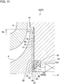
- FIG. 17 is a schematic diagram showing a schematic cross-sectional view in the vicinity of a back surface 16 of a compressor impeller 4 of an electric supercharger 2 (2F) according to another embodiment.
- FIG. 18 is a schematic diagram showing a schematic cross-sectional view in the vicinity of a back surface 16 of a compressor impeller 4 of an electric supercharger 2 (2G) according to another embodiment.
- FIG. 19 is a schematic diagram showing a schematic cross-sectional view in the vicinity of a back surface 16 of a compressor impeller 4 of an electric supercharger 2 (2H) according to another embodiment.
- FIG. 20 is a schematic diagram showing a schematic cross-sectional view in the vicinity of a back surface 16 of a compressor impeller 4 of an electric supercharger 2 (21) according to another embodiment.
- FIG. 21 is a schematic diagram showing a schematic cross-sectional view in the vicinity of a back surface 16 of a compressor impeller 4 of an electric supercharger 2 (2J) according to another embodiment.
- FIG. 22 is a schematic diagram showing a schematic cross-sectional view in the vicinity of a back surface 16 of a compressor impeller 4 of an electric supercharger 2 (2K) according to another embodiment.
- the basic configuration of the electric supercharger 2 (2F to 2K) is similar to that of the electric supercharger 2 depicted in FIG. 1 , except that the mechanical seal 20 is not provided.
- the same configurations are associated with the same reference numerals to omit description, and the characteristic configurations of the respective modified examples will be mainly described.
- the electric supercharger 2 (2F to 2H) further includes a rotary part 76 which protrudes outward in the radial direction from the rotational shaft 6, between the back-surface side casing 14 and the back surface 16 of the compressor impeller 4, and which is configured to rotate together with the rotational shaft 6. Further, the radially outer end 78 of the rotary part 76 is positioned on the outer side of the radially inner end 80 of the back-surface side casing 14 in the radial direction.
- the shape of the rotary part 76 is not particularly limited, the respective shapes of the rotary part 50 described with reference to FIGs. 8 to 10 may be applied. Furthermore, the rotary part 76 may be disposed at a distance from the back surface 16 of the compressor impeller 4 as depicted in FIG. 17 , or in contact with the back surface 16 of the compressor impeller 4 as depicted in FIGs. 18 and 19 , or integrally with the compressor impeller 4 or a non-depicted sleeve engaged with the rotational shaft 6. Further, as depicted in FIGs. 18 and 19 , the rotary part 76 may protrude toward the back surface 16 past the facing surface 21 of the back-surface side casing 14 that faces the back surface 16.
- the rotary part 76 may include a protruding portion 84 protruding in the axial direction so as to enter the inside of the recessed portion 82 as depicted in FIG. 19 .
- the electric supercharger 2 (21) includes a seal unit 9 instead of the mechanical seal 20 of the electric supercharger 2 (2B) depicted in FIG. 4 .
- a plurality of ribs 44 are disposed at intervals in the circumferential direction, on the back surface 16 of the compressor 4.
- the seal unit 9 includes a sleeve 86 and at least one piston ring 88 (in the depicted embodiment, two piston rings 88).
- the sleeve 86 is disposed such that an end side of the sleeve 86 is in contact with the back surface 16 of the compressor impeller 4, in a state where the sleeve 86 is engaged with the rotational shaft 6.
- the piston ring 88 is engaged with an annular groove disposed on the outer peripheral surface of the sleeve 86 and is in contact with the back-surface side casing 14, thereby sealing the gap between the rotational shaft 6 and the back-surface side casing 14.
- the electric supercharger 2 (2J) includes a seal unit 9 instead of the mechanical seal 20 of the electric supercharger 2 (2D) depicted in FIG. 11 .
- an abradable coating layer 90 is formed on at least a part of the facing surface 21 facing the back surface 16 of the compressor impeller 4 (the entire facing surface 21 in the depicted embodiment).
- the compressor impeller 4 receives a thrust force toward the upstream in the intake direction of air (left side in the drawing), in the axial direction, when air is compressed.
- the above electric supercharger 2 (2J) it is possible to reduce the pressure in the back-surface gap 'g' for the compressor impeller 4, and thus it is possible to reduce the thrust force in the axial direction.
- the electric supercharger 2 (2K) includes a seal unit 9 instead of the mechanical seal 20 of the electric supercharger 2 (2E) depicted in FIG. 13 .
- the abradable coating layer 90 is formed on at least a part of the back surface 16 of the compressor impeller 4.
- the compressor impeller 4 receives a thrust force toward the upstream in the intake direction of air (left side in the drawing), in the axial direction, when air is compressed.
- the above electric supercharger 2 (2K) it is possible to reduce the pressure in the back-surface gap 'g' for the compressor impeller 4, and thus it is possible to reduce the thrust force in the axial direction.
- the electric supercharger 2 (2A to 2E) is described as preferably applicable as a high-pressure stage supercharger of a two-stage supercharging system in the embodiment depicted in FIG. 16
- the electric supercharger 2 (2A to 2K) may be used as a low-pressure stage supercharger of a two-stage supercharging system as depicted in FIG. 23 .
- the electric supercharger 2 is disposed on the upstream side of the compressor 62 in the intake passage 56, and intake gas compressed by the electric supercharger 2 is supplied to the compressor 62 of the turbocharger 60.
- the engine device 110 is configured as a two-stage supercharging system in which the turbocharger 60 is provided as a high-pressure stage supercharger and the electric supercharger 2 is provided as a low-pressure stage supercharger.
- a bypass intake passage 66 bypassing the electric supercharger 2 is connected to the intake passage 56.
- a bypass valve 68 is disposed in the bypass intake passage 66. Further, by adjusting the valve opening degree of the bypass valve 68, the flow rate of intake gas flowing into the electric supercharger 2 is controlled.
- an intermediate cooler 70 for cooling intake gas to be supplied to the engine 54 is disposed.
- the engine device 110 includes an EGR passage 72 that connects the downstream side of the exhaust turbine 64 in the exhaust passage 58 and the upstream side of the electric supercharger 2 in the intake passage 56.
- An EGR valve 74 is disposed in the EGR passage 72. Further, by adjusting the valve opening degree of the EGR valve 74, exhaust gas having a flow rate corresponding to the valve opening degree returns to the intake passage 56. Further, intake gas containing the recirculated exhaust gas is supplied to the compressor impeller 4 of the electric supercharger 2.
- the bypass valve 68 is closed when the engine rotates at a low speed.
- the intake gas pressurized by the electric supercharger 2 serving as a low-pressure stage supercharger is supplied to the compressor 62 of the turbocharger 60 serving as a high-pressure stage supercharger as indicated by the arrow 'c', to be pressurized further.
- the boost pressure of the electric supercharger 2 is applied to the gap between the radially outer part and the radially inner part of the compressor in the electric supercharger 2, and causes intake air to enter the above described back-surface gap 'g'.
- the bypass valve 68 is open and the electric supercharger 2 is stopped when the engine rotates at a high speed.
- intake gas is supplied to the compressor 62 through the bypass intake passage 66, and thus substantially no intake air enters the back-surface gap 'g' of the electric supercharger 2.
Landscapes
- Engineering & Computer Science (AREA)
- Mechanical Engineering (AREA)
- General Engineering & Computer Science (AREA)
- Chemical & Material Sciences (AREA)
- Combustion & Propulsion (AREA)
- Structures Of Non-Positive Displacement Pumps (AREA)
- Supercharger (AREA)
Abstract
Description
- The present disclosure relates to an electric supercharger.
- In an engine device of an automobile or the like, to improve the engine fuel consumption and the efficiency, an exhaust turbine is driven by exhaust gas discharged from the engine to coaxially drive a compressor disposed in an intake passage and compress intake gas supplied to engine, which is called "supercharging".
- In this supercharging using a turbocharger, the torque and the output during low-speed rotation of the engine may raise problems, due to response delay during low-speed rotation of the engine, called turbo lag. A known technique to make up for the response delay due to turbo lag is a two-stage supercharging system which includes a turbocharger driven by exhaust gas and an electric supercharger driven by an electric motor (see Patent Document 1).
- Patent Document 1:
JP2015-537162A (translation of a PCT - Meanwhile, in an electric supercharger, the compressor is driven by a motor, unlike a turbocharger. Thus, devices such as a motor and an inverter substrate are disposed behind the compressor (between the compressor impeller and the bearing).
- Thus, when a leakage flow passes through the gap between the back surface of the compressor impeller and the casing and enters the bearing side, the leakage flow may affect devices such as the motor and the inverter substrate.
- In particular, in a case where a part of exhaust gas is recirculated in a two-stage supercharging system including an EGR and a case where an intermediate cooler is used, and a case where blow-by gas is returned to the inlet of the compressor, for instance, air containing condensed water is taken in from the inlet of the compressor, and thus a leakage flow passing through the gap between the back surface of the compressor impeller and entering the bearing side may cause trouble in operation of devices such as the motor and the inverter.
- Further, in particular, in a case where an electric supercharger is applied to the high-pressure stage of a two-stage supercharging system, high-temperature and high-pressure air flows in from the inlet of the compressor. Thus, a leakage flow passing through the gap between the back surface of the compressor impeller and entering the bearing side may cause trouble in operation of devices such as the motor and the inverter.
- At least one embodiment of the present invention was made in view of the above conventional problem. An object of at least one embodiment of the present invention is to provide an electric supercharger capable of suppressing entry of a leakage flow to the bearing side via the gap between the back surface of the compressor impeller and the casing.
-
- (1) According to at least one embodiment of the present invention, an electric supercharger includes: a compressor impeller; a motor configured to transmit a driving force to the compressor impeller via a rotational shaft; a back-surface side casing facing a back surface of the compressor impeller via a gap and surrounding the rotational shaft; a bearing disposed between the back-surface side casing and the rotational shaft so as to support the rotational shaft rotatably; and a mechanical seal positioned between the back surface of the compressor impeller and the bearing in an axial direction of the compressor impeller and configured to seal a gap between the rotational shaft and the back-surface side casing.
With the above electric supercharger (1), it is possible to suppress entry of a leakage flow from the gap between the back surface and the back-surface side casing (hereinafter, referred to as "back-surface gap") to the bearing by using the mechanical seal, and suppress inflow of the leakage flow into electric devices such as the motor. Thus, it is possible to suppress occurrence of malfunction or the like of the electric devices, and operate the electric supercharger stably. - (2) In some embodiment, in the above electric supercharger (1), the mechanical seal includes: a stationary ring supported on the back-surface side casing; a rotary ring protruding from the rotational shaft toward an outer side in a radial direction of the compressor impeller and facing the stationary ring so as to be capable of being in contact with the stationary ring in the axial direction of the compressor impeller, the rotary ring being configured to rotate with the rotational shaft; and a biasing member configured to bias one of the rotary ring or the stationary ring toward the other one of the rotary ring or the stationary ring. A groove is formed on a facing surface which is one of a surface of the rotary ring which faces the stationary ring or a surface of the stationary ring which faces the rotary ring.
With the above electric supercharger (2), when rotation of the compressor impeller is stopped, as the biasing member pushes one of the rotary ring or the stationary ring against the other one of the rotary ring or the stationary ring, the mechanical seal functions as a contact seal. Accordingly, it is possible to suppress entry of a leakage flow from the back-surface gap to the bearing, and suppress inflow of the leakage flow into electric devices such as the motor. Thus, it is possible to suppress occurrence of malfunction or the like of the electric devices, and operate the electric supercharger stably.
Further, when the compressor impeller is rotating, the pressure of gas inside the groove having a pressure increased by a centrifugal force separates the stationary ring and the rotary ring against the biasing force of the biasing member. Accordingly, the stationary ring and the rotary ring separate from each other (not in contact). Nevertheless, with the pressure of the space on the inner side of the facing surface being higher than the pressure of the space on the outer side of the facing surface, it is possible to suppress entry of a leakage flow from the back-surface gap to the bearing. Accordingly, it is possible to suppress inflow of the leakage flow to electric devices such as the motor. Thus, it is possible to suppress occurrence of malfunction or the like of the electric devices, and operate the electric supercharger stably. - (3) In some embodiments, in the above electric supercharger (1) or (2), the back surface of the compressor impeller has a plurality of ribs disposed on the back surface at intervals in a circumferential direction of the compressor impeller.
With the above electric supercharger (3), by providing the plurality of ribs, a centrifugal force toward the outer side in the radial direction is applied to air in the back-surface gap upon rotation of the compressor impeller, and thereby it is possible to decrease the pressure of the radially inner part of the back-surface gap. Accordingly, it is possible to suppress entry of a leakage flow from the back-surface gap to the bearing, and suppress inflow of the leakage flow into electric devices such as the motor. Further, when applied to the above electric supercharger (2), by reducing the pressure of the radially inner part of the back-surface gap, it is possible to decrease the spring force of the biasing member required to move the stationary ring appropriately, which makes it possible to suppress development of wear due to friction between the stationary ring and the rotary ring. - (4) In some embodiments, in the above electric supercharger (3), each of the ribs is disposed to so as to extend along a direction which intersects with the circumferential direction of the compressor impeller.
With the above electric supercharger (4), the plurality of ribs extending in a direction orthogonal to the circumferential direction rotates with the compressor impeller, and thus it is possible to apply the centrifugal force toward the outer side in the radial direction effectively to air in the back-surface gap, and reduce the pressure of the radially inner part of the back-surface gap. Accordingly, it is possible to suppress entry of a leakage flow from the back-surface gap to the bearing, and suppress inflow of the leakage flow into electric devices such as the motor. - (5) In some embodiments, in the above configuration (3) or (4), each of the ribs has an airfoil shape.
With the above electric supercharger (5), it is possible to form an airflow toward the outer side in the radial direction effectively with the ribs having an airfoil shape, in the back-surface gap upon rotation of the compressor impeller. Accordingly, it is possible to suppress entry of a leakage flow from the back-surface gap to the bearing, and suppress inflow of the leakage flow into electric devices such as the motor. - (6) In some embodiments, in the electric supercharger according to any one of the above (3) to (5), each of the ribs is disposed so as to extend in a direction inclined from a radial direction of the compressor impeller such that a radially outer end of the rib is positioned on an upstream side of a radially inner end of the rib with respect to a rotational direction of the compressor impeller.
With the above electric supercharger (6), with the ribs being inclined in the above direction, it is possible to suppress inflow of air into the gaps between the ribs from the outer side in the radial direction, during rotation of the compressor impeller. Accordingly, it is possible to suppress entry of a leakage flow from the back-surface gap to the bearing, and suppress inflow of the leakage flow into electric devices such as the motor. - (7) In some embodiments, the electric supercharger according to any one of the above (1) to (6) further includes, between the mechanical seal and the back surface of the compressor impeller, a rotary part protruding from the rotational shaft toward an outer side in a radial direction of the compressor impeller, the rotary part being configured to rotate together with the rotational shaft.
With the above electric supercharger (7), upon rotation of the compressor impeller, a centrifugal force toward the outer side in the radial direction is applied to air in the back-surface gap in accordance with rotation of the rotary part, and thereby it is possible to decrease the pressure of the radially inner part of the back-surface gap. Accordingly, it is possible to suppress entry of a leakage flow from the back-surface gap to the bearing, and suppress inflow of the leakage flow into electric devices such as the motor. Further, when applied to the above electric supercharger (2), by reducing the pressure of the radially inner part of the back-surface gap, it is possible to decrease the spring force of the biasing member required to move the stationary ring appropriately, which makes it possible to suppress development of wear due to friction between the stationary ring and the rotary ring. - (8) In some embodiments, the electric supercharger according to any one of the above (1) to (7) further includes an abradable coating layer formed on at least a part of the back surface of the compressor impeller, or at least a part of a surface of the back-surface side casing which faces the back surface of the compressor impeller.
With the above electric supercharger (8), in a case where the abradable coating layer is formed on at least a part of the back surface of the compressor impeller, the abradable coating layer would be ground upon rotation of the compressor impeller even if the abradable coating layer formed on the back surface of the compressor impeller makes contact with a surface of the back-surface side casing that faces the back surface of the compressor impeller. Thus, it is possible to reduce the clearance between the back surface and the back-surface side casing.
Furthermore, in a case where the abradable coating layer is formed on at least a part of a surface of the back-surface side casing that faces the back surface of the compressor impeller, the abradable coating layer would be ground upon rotation of the compressor impeller even if the abradable coating layer formed on a facing surface of the back-surface side casing that faces the back surface of the compressor impeller makes contact with the back surface of the compressor impeller. Thus, it is possible to reduce the clearance between the back surface and the back-surface side casing.
Accordingly, it is possible to promote a pressure decrease toward the inner side in the radial direction, in the back-surface gap. Thus, it is possible to reduce the axial-directional pressure difference between the pressure of the radially inner part and the pressure near the bearing, of the back-surface gap, and thus it is possible to suppress entry of a leakage flow toward the bearing from the back-surface gap. Accordingly, it is possible to suppress inflow of the leakage flow into electric devices such as the motor and an inverter. Thus, it is possible to suppress occurrence of malfunction or the like of the electric devices, and operate the electric supercharger stably.
Further, the compressor impeller receives a thrust force toward the upstream in the intake direction of air, in the axial direction, when air is compressed. In the above electric supercharger, it is possible to reduce the pressure in the back-surface gap for the compressor impeller, and thus it is possible to reduce the thrust force in the axial direction.
Further, by promoting the pressure decrease toward the inner side in the radial direction in the back-surface gap to reduce the pressure of the radially inner part of the back-surface gap, it is possible to decrease the spring force of the biasing member required to move the stationary ring of the mechanical seal appropriately, which makes it possible to suppress development of wear due to friction between the stationary ring and the rotary ring. - (9) In some embodiments, in the electric supercharger (8), a ratio G/R of a size G of a gap between the back surface of the compressor impeller and the back-surface side casing to an outer diameter R of the compressor impeller is less than 0.5%.
With the above electric supercharger (9), it is possible to promote a pressure decrease toward the inner side in the radial direction, in the back-surface gap, effectively. According to the inventors of the present invention, when comparing a case where the abradable coating layer is provided and the ratio C/Ri is set to be 0.8% and a case where the abradable coating layer is not provided and C/Ri is set to be 0.25%, the former can reduce more pressure of the radially inner part of the back-surface gap by 26% compared to the latter. - (10) In some embodiments, the electric supercharger according to any one of the above (1) to (9) further includes an internal-pressure adjustment mechanism configured to adjust a pressure inside the back-surface side casing by bringing into communication an inside and an outside of the back-surface side casing.
- With the above electric supercharger (10), in the electric supercharger according to any one of the above (1) to (9), even in a case where the pressure of the radially inner part of the back-surface gap is low, it is possible to stabilize the pressure balance across the mechanical seal by adjusting the pressure inside and outside the back-surface side casing by using the pressure adjustment mechanism. Accordingly, it is possible to suppress entry of a leakage flow to the bearings through the back-surface gap stably with the mechanical seal.
- According to at least one embodiment of the present invention, it is possible to provide an electric supercharger capable of suppressing entry of a leakage flow to the bearing side via the gap between the back surface of the compressor impeller and the casing.
-
-
FIG. 1 is a schematic diagram showing a schematic cross-sectional view of anelectric supercharger 2 according to an embodiment. -
FIG. 2 is a schematic diagram showing a schematic cross-sectional view in the vicinity of aback surface 16 of acompressor impeller 4 of an electric supercharger 2 (2A) according to an embodiment, showing a configuration example of amechanical seal 20. -
FIG. 3 is a view of acompressor impeller 4 in rotation, in the electric supercharger 2 (2A) depicted inFIG. 2 . -
FIG. 4 is a schematic diagram showing a schematic cross-sectional view in the vicinity of aback surface 16 of acompressor impeller 4 of an electric supercharger 2 (2B) according to an embodiment. -
FIG. 5 is a diagram showing a configuration example of theribs 44 depicted inFIG. 4 , showing an example of arrangement of theribs 44 in an axial-directional view. -
FIG. 6 is a diagram showing a configuration example of theribs 44 depicted inFIG. 4 , showing an example of arrangement of theribs 44 in an axial-directional view. -
FIG. 7 is a schematic diagram showing a schematic cross-sectional view in the vicinity of aback surface 16 of acompressor impeller 4 of an electric supercharger 2 (2C) according to an embodiment. -
FIG. 8 is a diagram showing a configuration example of therotary part 50 depicted inFIG. 7 , showing an example of the shape of therotary part 50 in an axial-directional view. -
FIG. 9 is a diagram showing a configuration example of therotary part 50 depicted inFIG. 7 , showing an example of the shape of therotary part 50 in an axial-directional view. -
FIG. 10 is a diagram showing a configuration example of therotary part 50 depicted inFIG. 7 , showing an example of the shape of therotary part 50 in an axial-directional view. -
FIG. 11 is a schematic diagram showing a schematic cross-sectional view in the vicinity of aback surface 16 of acompressor impeller 4 of an electric supercharger 2 (2D) according to an embodiment. -
FIG. 12 is a graph showing the relationship between the radial-directional position R and the gauge pressure P of the back-surface gap 'g'. The dotted line indicates an electric supercharger 2 (2A) not including anabradable coating layer 90, and the solid line indicates an electric supercharger 2 (2D) including anabradable coating layer 90 formed on the facingsurface 21. -
FIG. 13 is a schematic diagram showing a schematic cross-sectional view in the vicinity of aback surface 16 of acompressor impeller 4 of an electric supercharger 2 (2E) according to an embodiment. -
FIG. 14 is a diagram showing an example of arrangement of acommunication hole 53 that serves as an internal-pressure adjustment mechanism. -
FIG. 15 is a diagram showing an example of arrangement of acommunication hole 53 that serves as an internal-pressure adjustment mechanism. -
FIG. 16 is a schematic configuration diagram of anengine device 100 to which an electric supercharger 2 (2A to 2E) can be applied preferably. -
FIG. 17 is a schematic diagram showing a schematic cross-sectional view in the vicinity of aback surface 16 of acompressor impeller 4 of an electric supercharger 2 (2F) according to another embodiment. -
FIG. 18 is a schematic diagram showing a schematic cross-sectional view in the vicinity of aback surface 16 of acompressor impeller 4 of an electric supercharger 2 (2G) according to another embodiment. -
FIG. 19 is a schematic diagram showing a schematic cross-sectional view in the vicinity of aback surface 16 of acompressor impeller 4 of an electric supercharger 2 (2H) according to another embodiment. -
FIG. 20 is a schematic diagram showing a schematic cross-sectional view in the vicinity of aback surface 16 of acompressor impeller 4 of an electric supercharger 2 (21) according to another embodiment. -
FIG. 21 is a schematic diagram showing a schematic cross-sectional view in the vicinity of aback surface 16 of acompressor impeller 4 of an electric supercharger 2 (2J) according to another embodiment. -
FIG. 22 is a schematic diagram showing a schematic cross-sectional view in the vicinity of aback surface 16 of acompressor impeller 4 of an electric supercharger 2 (2K) according to another embodiment. -
FIG. 23 is a schematic configuration diagram of anengine device 100 to which an electric supercharger 2 (2A to 2K) can be applied. - Embodiments of the present invention will now be described in detail with reference to the accompanying drawings. It is intended, however, that unless particularly identified, dimensions, materials, shapes, relative positions and the like of components described in the embodiments shall be interpreted as illustrative only and not intended to limit the scope of the present invention.
- For instance, an expression of relative or absolute arrangement such as "in a direction", "along a direction", "parallel", "orthogonal", "centered", "concentric" and "coaxial" shall not be construed as indicating only the arrangement in a strict literal sense, but also includes a state where the arrangement is relatively displaced by a tolerance, or by an angle or a distance whereby it is possible to achieve the same function.
- For instance, an expression of an equal state such as "same" "equal" and "uniform" shall not be construed as indicating only the state in which the feature is strictly equal, but also includes a state in which there is a tolerance or a difference that can still achieve the same function.
- Further, for instance, an expression of a shape such as a rectangular shape or a cylindrical shape shall not be construed as only the geometrically strict shape, but also includes a shape with unevenness or chamfered corners within the range in which the same effect can be achieved.
- On the other hand, an expression such as "comprise", "include", "have", "contain" and "constitute" are not intended to be exclusive of other components.
-
FIG. 1 is a schematic diagram showing a schematic cross-sectional view of anelectric supercharger 2 according to an embodiment. - In an illustrative embodiment depicted in
FIG. 1 , theelectric supercharger 2 includes acompressor impeller 4, arotational shaft 6, animpeller casing 8,bearings motor 12, a back-surface side casing 14 (stationary member), and amechanical seal 20. - Hereinafter, unless otherwise stated, the circumferential direction of the
compressor impeller 4 is referred to as merely "circumferential direction", the radial direction of thecompressor impeller 4 is referred to as merely "radial direction", and the axial direction of thecompressor impeller 4 is referred to as merely "axial direction". - The
impeller casing 8 is formed so as to surround thecompressor impeller 4, and is configured to guide intake air to the inlet of thecompressor impeller 4 and discharge air compressed by thecompressor impeller 4. - The
bearings rotational shaft 6 rotatably, and as grease-lubrication type bearings which contain grease as a lubricating agent sealed around balls held between an inner race and an outer race which are not depicted. The bearing 10A is positioned between themechanical seal 20 and themotor 12 in the axial direction, and is positioned between the back-surface side casing 14 and therotational shaft 6 in the radial direction. The bearing 10B is positioned opposite to thebearing 10A across themotor 12 in the axial direction, and is positioned between the back-surface side casing 14 and therotational shaft 6 in the radial direction. - The
motor 12 is configured to transmit a driving force to thecompressor impeller 4 via therotational shaft 6. Themotor 12 is positioned between the bearing 10A and the bearing 10B in the axial direction. - The back-
surface side casing 14 faces theback surface 16 of thecompressor impeller 4 via a gap, and is configured to surround themechanical seal 20, thebearings motor 12. Further, the back-surface side casing 14 includes aninverter housing portion 18 for housing an inverter (not depicted), on the opposite side from themotor 12 across the bearing 10B. - The
mechanical seal 20 is positioned between theback surface 16 of thecompressor impeller 4 and thebearing 10A in the axial direction, and is configured to seal the gap between therotational shaft 6 and the back-surface side casing 14. -
FIG. 2 is a schematic diagram showing a schematic cross-sectional view in the vicinity of aback surface 16 of acompressor impeller 4 of an electric supercharger 2 (2A) according to an embodiment, showing a configuration example of amechanical seal 20.FIG. 3 is a view of acompressor impeller 4 in rotation, in the electric supercharger 2 (2A) depicted inFIG. 2 . - In some embodiments, as depicted in
FIGs. 2 and3 , themechanical seal 20 includes astationary ring 22, arotary ring 24, and a biasingmember 26. - The
stationary ring 22 is formed to have an annular shape along the circumferential direction, and is supported on the back-surface side casing 14. Thestationary ring 22 is at a position that is between therotary ring 24 and the back-surface side casing 14, and between the back-surface side casing 14 and therotational shaft 6. - The
rotary ring 24 is disposed between theback surface 16 of thecompressor impeller 4 and thestationary ring 22, and is configured to have an annular shape along the circumferential direction so as to face thestationary ring 22 so as to be capable of being in contact with thestationary ring 22. Therotary ring 24 is configured to protrude toward an outer side from therotational shaft 6 in the radial direction, and rotate together with therotational shaft 6. - The biasing
member 26 is configured to bias one of thestationary ring 22 or therotary ring 24 toward the other one of thestationary ring 22 or therotary ring 24. In the depicted embodiment, the biasingmember 26 includes an elastic member (e.g., coil spring, disc spring, or rubber), and is interposed between thestationary ring 22 and the back-surface side casing 14 so as to bias thestationary ring 22 toward therotary ring 24. - Furthermore, a
groove 34 is formed on a facingsurface 32, which is one of asurface 28 of therotary ring 24 that faces thestationary ring 22, or asurface 30 of thestationary ring 22 that faces the rotary ring 24 (in the depicted embodiment, the facingsurface 32 is thesurface 28 of therotary ring 24 facing the stationary ring 22). As depicted inFIG. 2 , thegroove 34 on the facingsurface 32 is formed so as to be in communication with aspace 36 on the inner side of the facingsurface 32 in the radial direction (space between thestationary ring 22 and the rotational shaft 6), and so as not to be in communication with thespace 38 on the outer side of the facingsurface 32 in the radial direction (of the back-surface gap 'g' between theback surface 16 and the back-surface side casing 14, the outer portion of the stationary ring 22), in a state where thestationary ring 22 and therotary ring 24 are in contact. That is, in a state where thestationary ring 22 and therotary ring 24 are in contact, thegroove 34 is disposed from a position on the inner side, in the radially direction, of the radiallyinner end 40 of the contact portion between thestationary ring 22 and therotary ring 24 on the facingsurface 32 to a position that does not reach the radiallyouter end 42 of the contact portion between thestationary ring 22 and therotary ring 24, on the facingsurface 32. - With the above configuration, when rotation of the
compressor impeller 4 is stopped, as depicted inFIG. 2 , as the biasingmember 26 pushes thestationary ring 22 against therotary ring 24, themechanical seal 20 functions as a contact seal. Accordingly, it is possible to suppress entry of a leakage flow from the back-surface gap 'g' to the bearing 10A, and suppress inflow of the leakage flow into electric devices such as themotor 12. Thus, it is possible to suppress occurrence of malfunction or the like of the electric devices, and operate the electric supercharger stably. - Further, when the
compressor impeller 4 is rotating, the pressure of gas inside thegroove 34 having a pressure increased by a centrifugal force pushes thestationary ring 22 into the side of the biasingmember 26, as depicted inFIG. 3 . Accordingly, thestationary ring 22 and therotary ring 24 separate from each other (not in contact). Nevertheless, with the pressure of thespace 38 on the inner side of the facingsurface 32 being higher than the pressure of thespace 38 on the outer side of the facingsurface 32, it is possible to suppress entry of a leakage flow from the back-surface gap 'g' to thebearing 10A. Accordingly, it is possible to suppress inflow of the leakage flow into electric devices such as themotor 12. Thus, it is possible to suppress occurrence of malfunction or the like of the electric devices, and operate the electric supercharger stably. - Next, some modified examples of the
electric supercharger 2 will be described with reference toFIGs. 4 to 13 . In the following modified examples, the same configurations as those of the electric supercharger 2 (2A) are associated with the same reference numerals to omit description, and the characteristic configurations of the respective modified examples will be mainly described. -
FIG. 4 is a schematic diagram showing a schematic cross-sectional view in the vicinity of aback surface 16 of acompressor impeller 4 of an electric supercharger 2 (2B) according to an embodiment.FIG. 5 is a diagram showing a configuration example of theribs 44 depicted inFIG. 4 , showing an example of arrangement of theribs 44 in an axial-directional view.FIG. 6 is a diagram showing a configuration example of theribs 44 depicted inFIG. 4 , showing an example of arrangement of theribs 44 in an axial-directional view. - In some embodiments, as depicted in
FIGs. 4 to 6 , a plurality ofribs 44 are disposed at intervals in the circumferential direction, on theback surface 16 of thecompressor 4. With the above configuration, by providing the plurality ofribs 44, a centrifugal force toward the outer side in the radial direction is applied to air in the back-surface gap 'g' upon rotation of thecompressor impeller 4, and thereby it is possible to decrease the pressure of the radially inner part of the back-surface gap 'g'. Accordingly, it is possible to suppress entry of a leakage flow from the back-surface gap 'g' to the bearing 10A, and suppress inflow of the leakage flow into electric devices such as the motor. Further, by reducing the pressure of the radially inner part of the back-surface gap 'g', it is possible to decrease the spring force of the biasingmember 26 required to move thestationary ring 22 appropriately, which makes it possible to suppress development of wear due to friction between thestationary ring 22 and therotary ring 24. - In some embodiments, as shown in
FIGs. 5 and6 for instance, each of theribs 44 is formed to extend along a direction that intersects with the circumferential direction. Further, in the embodiment depicted inFIG. 5 , the plurality ofribs 44 are disposed so as to extend in a radial fashion along a direction orthogonal to the circumferential direction (radial direction). - With the above configuration, the plurality of
ribs 44 extending in a direction orthogonal to the circumferential direction rotates with thecompressor impeller 4, and thus it is possible to apply the centrifugal force toward the outer side in the radial direction effectively to air in the back-surface gap 'g', and reduce the pressure of the radially inner part of the back-surface gap 'g'. Accordingly, it is possible to suppress entry of a leakage flow from the back-surface gap 'g' to the bearing 10A, and suppress inflow of the leakage flow into electric devices such as the motor. - In some embodiments, as shown in
FIG. 6 , each of theribs 44 has an airfoil shape. With the above configuration, it is possible to form an airflow toward the outer side in the radial direction effectively with theribs 44 having an airfoil shape, in the back-surface gap 'g' upon rotation of thecompressor impeller 4. Accordingly, it is possible to suppress entry of a leakage flow from the back-surface gap 'g' to the bearing 10A, and suppress inflow of the leakage flow into electric devices such as themotor 12. - In some embodiments, as depicted in
FIG. 6 for instance, eachrib 44 is disposed so as to extend in a direction inclined from the radial direction, such that the radiallyouter end 46 of therib 44 is positioned on the upstream side of the radiallyinner end 48 of therib 44, with respect to the rotational direction of thecompressor impeller 4. - With the above configuration, with the
ribs 44 being inclined in the above direction, it is possible to suppress inflow of air into the gaps between theribs 44 from the outer side in the radial direction, during rotation of thecompressor impeller 4. Accordingly, it is possible to suppress entry of a leakage flow from the back-surface gap 'g' to the bearing 10A, and suppress inflow of the leakage flow into electric devices such as themotor 12. -
FIG. 7 is a schematic diagram showing a schematic cross-sectional view in the vicinity of aback surface 16 of acompressor impeller 4 of an electric supercharger 2 (2C) according to an embodiment.FIG. 8 is a diagram showing a configuration example of therotary part 50 depicted inFIG. 7 , showing an example of the shape of therotary part 50 in an axial-directional view.FIG 9 is a diagram showing a configuration example of therotary part 50 depicted inFIG. 7 , showing an example of the shape of therotary part 50 in an axial-directional view.FIG. 10 is a diagram showing a configuration example of therotary part 50 depicted inFIG. 7 , showing an example of the shape of therotary part 50 in an axial-directional view. - In some embodiments, as depicted in
FIG. 7 , the electric supercharger further includes arotary part 50 which protrudes outward in the radial direction from therotational shaft 6, between themechanical seal 20 and theback surface 16 of thecompressor impeller 4, and which is configured to rotate together with therotational shaft 6. - With the above configuration, a centrifugal force toward the outer side in the radial direction is applied to air in the back-surface gap 'g' in accordance with rotation of the
rotary part 50, and thereby it is possible to decrease the pressure of the radially inner part of the back-surface gap 'g'. Accordingly, it is possible to suppress entry of a leakage flow from the back-surface gap 'g' to the bearing 10A, and suppress inflow of the leakage flow into electric devices such as themotor 12. Further, by reducing the pressure of the radially inner part of the back-surface gap 'g', it is possible to decrease the spring force of the biasingmember 26 required to move thestationary ring 22 appropriately, which makes it possible to suppress development of wear due to friction between thestationary ring 22 and therotary ring 24. - The shape of the
rotary part 50 is not particularly limited. For instance, the rotary part 51 may have an annular shape as depicted inFIG. 8 , or may have a plurality of protrusions 52 (fourprotrusions 52 in the depicted embodiment) protruding outward in the radial direction from the annular shape as depicted inFIGs. 9 and 10 . Theprotrusions 52 may protrude in a radial fashion along the radial direction as depicted inFIG. 9 for instance, or may have a tapered shape protruding diagonally with respect to the radial direction as depicted inFIG. 10 . -
FIG. 11 is a schematic diagram showing a schematic cross-sectional view in the vicinity of aback surface 16 of acompressor impeller 4 of an electric supercharger 2 (2D) according to an embodiment.FIG. 12 is a graph showing the relationship between the radial-directional position R and the gauge pressure P of the back-surface gap 'g'. The dotted line indicates an electric supercharger 2 (2A) not including anabradable coating layer 90, and the solid line indicates an electric supercharger 2 (2D) including anabradable coating layer 90 formed on the facingsurface 21.FIG. 13 is a schematic diagram showing a schematic cross-sectional view in the vicinity of aback surface 16 of acompressor impeller 4 of an electric supercharger 2 (2E) according to an embodiment. - In some embodiments, as depicted in
FIG. 11 , of the back-surface side casing 14, anabradable coating layer 90 is formed on at least a part of the facingsurface 21 facing theback surface 16 of the compressor impeller 4 (the entire facingsurface 21 in the depicted embodiment). - With the above configuration, the
abradable coating layer 90 would be ground upon rotation of thecompressor impeller 4 even if theabradable coating layer 90 formed on the facingsurface 21 makes contact with theback surface 16 of thecompressor impeller 4. Thus, it is possible to reduce the clearance C between theback surface 16 and the back-surface side casing 14 (distance between theback surface 16 and the back-surface side casing 14). Accordingly, it is possible to promote a pressure decrease toward the inner side in the radial direction, in the back-surface gap 'g', as described below. -
FIG. 12 is a graph schematically showing the relationship between the radial-directional position R and the gauge pressure P of the back-surface gap 'g'. The dotted line indicates an electric supercharger 2 (2A) not including anabradable coating layer 90, and the solid line indicates an electric supercharger 2 (2D) including anabradable coating layer 90 formed on the facingsurface 21. Herein, the clearance C between theback surface 16 and the back-surface side casing 14 of the electric supercharger 2 (2D) is set to be smaller than the clearance between theback surface 16 and the back-surface side casing 14 of the electric supercharger 2 (2A). - As depicted in
FIG. 12 , in both of the electric supercharger 2 (2A) and the electric supercharger 2 (2D), the pressure decreases in the back-surface gap g, toward the inner side in the radial direction. Particularly in a region where the radial-directional position R is small, the pressure in the back-surface gap 'g' in the electric supercharger 2(2D) is reduced considerably compared to that in the electric supercharger 2 (2A). - Accordingly, with the
electric supercharger 2, by promoting the pressure decrease toward the inner side in the radial direction in the back-surface gap 'g', it is possible to reduce the axial-directional pressure difference between the pressure of the radially inner part (pressure near the mechanical seal 20) of the back-surface gap 'g' and the pressure near the bearing 10A and thus it is possible to suppress entry of a leakage flow toward the bearing 10A (toward the mechanical seal 20) from the back-surface gap 'g'. Accordingly, it is possible to suppress inflow of the leakage flow into electric devices such as themotor 12 and an inverter (not depicted). Thus, it is possible to suppress occurrence of malfunction or the like of the electric devices, and operate theelectric supercharger 2 stably. - Further, the
compressor impeller 4 receives a thrust force toward the upstream in the intake direction of air (left side in the drawing), in the axial direction, when air is compressed. In the aboveelectric supercharger 2, it is possible to reduce the pressure in the back-surface gap 'g' for thecompressor impeller 4, and thus it is possible to reduce the thrust force in the axial direction. - Further, by promoting the pressure decrease toward the inner side in the radial direction in the back-surface gap 'g' to reduce the pressure of the radially inner part of the back-surface gap 'g', it is possible to decrease the spring force of the biasing
member 26 required to move thestationary ring 22 appropriately, which makes it possible to suppress development of wear due to friction between thestationary ring 22 and therotary ring 24. - In an embodiment, in
FIG. 11 , the ratio C/Ri of the clearance C between theback surface 16 of thecompressor impeller 4 and the back-surface side casing 14 to the outer diameter Ri of thecompressor impeller 4 is less than 0.5%. - With the above configuration, it is possible to promote a pressure decrease toward the inner side in the radial direction, in the back-surface gap 'g', effectively. According to the inventors of the present invention, when comparing a case where the
abradable coating layer 90 is provided and the ratio C/Ri is set to be 0.8% and a case where theabradable coating layer 90 is not provided and C/Ri is set to be 0.25%, the former can reduce more pressure of the radially inner part of the back-surface gap 'g' by 26% compared to the latter. - In an embodiment, as depicted in
FIG. 13 , theabradable coating layer 90 is formed on at least a part of theback surface 16 of thecompressor impeller 4. Furthermore, the ratio C/Ri of the clearance C between theback surface 16 of thecompressor impeller 4 and the back-surface side casing 14 to the outer diameter Ri of thecompressor impeller 4 is less than 0.5%. - With the above configuration, the
abradable coating layer 90 would be ground upon rotation of thecompressor impeller 4 even if theabradable coating layer 90 formed on theback surface 16 of thecompressor impeller 4 makes contact with the facingsurface 21 of the back-surface side casing 14. Thus, it is possible to reduce the clearance C between theback surface 16 and the back-surface side casing 14. Accordingly, it is possible to promote a pressure decrease toward the inner side in the radial direction, in the back-surface gap 'g'. - Thus, it is possible to reduce the axial-directional pressure difference between the pressure of the radially inner part of the back-surface gap 'g' (pressure near the mechanical seal 20) and the pressure near the bearing 10A, and thus it is possible to suppress entry of a leakage flow toward the bearing 10A (toward the mechanical seal 20) from the back-surface gap 'g'. Accordingly, it is possible to suppress inflow of the leakage flow into electric devices such as the
motor 12 and an inverter (not depicted). Thus, it is possible to suppress occurrence of malfunction or the like of the electric devices, and operate the electric supercharger stably. - Further, it is possible to reduce the pressure of the back-surface gap 'g' by reducing the clearance C, and thus it is possible to reduce the thrust force in the axial direction in the
compressor impeller 4. - Further, by promoting the pressure decrease toward the inner side in the radial direction in the back-surface gap 'g' to reduce the pressure of the radially inner part of the back-surface gap 'g', it is possible to decrease the spring force of the biasing
member 26 required to move thestationary ring 22 appropriately, which makes it possible to suppress development of wear due to friction between thestationary ring 22 and therotary ring 24. - In some embodiments, as depicted in
FIGs. 14 and15 for instance, the electric supercharger 2 (2A to 2E) further includes acommunication hole 53 serving as an internal-pressure adjustment mechanism, configured to adjust the pressure inside the back-surface side casing 14 by bringing the inside and the outside of the back-surface side casing 14 into communication. Thecommunication hole 53 may be disposed on the compressor side of the back-surface side casing 14 as depicted inFIG. 14 , or on the inverter side as depicted inFIG. 15 , or on both sides. The position, shape, and dimension like hole diameter of thecommunication hole 53 are to be designed to be optimum in accordance with the size of theelectric supercharger 2. Further, in the embodiment depicted inFIGs. 14 and15 , on the outer end portion side of thecommunication hole 53, awaterproof ventilation filter 55 is disposed, which protects the inside of the back-surface side casing 14 from dust, water, oil, and the like while adjusting the pressure and the temperature inside the back-surface side casing 14. - With the above configuration, even in a case where the pressure of the radially inner part of the back-surface gap 'g' is low, it is possible to stabilize the pressure balance across the
mechanical seal 20 by adjusting the pressure inside and outside the back-surface side casing 14 through thecommunication hole 53. Accordingly, it is possible to suppress entry of a leakage flow to thebearings mechanical seal 20. -
FIG. 16 is a schematic configuration diagram of anengine device 100 to which the above described electric supercharger 2 (2A to 2E) can be applied preferably.FIG. 16 is a diagram of an embodiment of anengine device 100 in a case where theelectric supercharger 2 is used as a high-pressure stage supercharger of a two-stage supercharging system. - The
engine device 100 depicted inFIG. 16 includes, as depicted in the drawing, anengine 54, anintake passage 56 through which intake gas to be supplied to theengine 54 flows, anexhaust passage 58 through which exhaust gas discharged from theengine 54 flows, aturbocharger 60, and the above describedelectric supercharger 2. - The
turbocharger 60 includes anexhaust turbine 64 disposed in theexhaust passage 58, acompressor 62 disposed in theintake passage 56, and anexhaust turbine shaft 63 coupling theexhaust turbine 64 and thecompressor 62. Theturbocharger 60 is configured such that theexhaust turbine 64 is driven by exhaust gas discharged from theengine 54, and thereby thecompressor 62 is coaxially driven via theturbine shaft 63, so as to supercharge intake gas flowing through theintake passage 56. - The
electric supercharger 2 is disposed on the downstream side of thecompressor 62 in theintake passage 56, and intake gas compressed by thecompressor 62 of theturbocharger 60 is supplied to thecompressor impeller 4 of theelectric supercharger 2. As described above, theengine device 100 of the present embodiment is configured as a two-stage supercharging system in which theturbocharger 60 is provided as a low-pressure stage supercharger and theelectric supercharger 2 is provided as a high-pressure stage supercharger. - A
bypass intake passage 66 bypassing theelectric supercharger 2 is connected to theintake passage 56. Abypass valve 68 is disposed in thebypass intake passage 66. Further, by adjusting the valve opening degree of thebypass valve 68, the flow rate of intake gas flowing into theelectric supercharger 2 is controlled. - Further, on the downstream side of the
electric supercharger 2 in theintake passage 56, an intermediate cooler 70 for cooling intake gas to be supplied to theengine 54 is disposed. - Furthermore, the
engine device 100 includes anEGR passage 72 that connects the downstream side of theexhaust turbine 64 in theexhaust passage 58 and the upstream side of thecompressor 62 in theintake passage 56. AnEGR valve 74 is disposed in theEGR passage 72. Further, by adjusting the valve opening degree of theEGR valve 74, exhaust gas having a flow rate corresponding to the valve opening degree returns to theintake passage 56. Further, intake gas containing the recirculated exhaust gas is supplied to thecompressor impeller 4 of theelectric supercharger 2. - In the
above engine device 100, thebypass valve 68 is closed when the engine rotates at a low speed. The intake gas pressurized by theturbocharger 60 serving as a low-pressure stage supercharger is supplied to theelectric supercharger 2 serving as a high-pressure stage supercharger as indicated by the arrow 'a', to be pressurized further. Thus, compared to a case where theelectric supercharger 2 is disposed at the low-pressure stage, the differential pressure between the radially outer part and the radially inner part of the compressor in theelectric supercharger 2 becomes high, and high-temperature and high-pressure intake air enters the above described back-surface gap 'g'. - Furthermore, in the
engine device 100, thebypass valve 68 is open and theelectric supercharger 2 is stopped when the engine rotates at a high speed. In this case, the intake gas pressurized by theturbocharger 60 serving as a low-pressure stage supercharger is supplied to the downstream side of theelectric supercharger 2 through thebypass intake passage 66, as indicated by the arrow 'b'. Thus, the boost pressure of theturbocharger 60 creates a differential pressure between the radially outer part and the radially inner part of the compressor in theelectric supercharger 2, and causes intake air to enter the above described back-surface gap 'g'. - In this regard, by applying the above described electric supercharger 2 (2A to 2E) to the
engine device 100, it is possible to suppress entry of high-temperature and high-pressure intake air to the bearing side via the back-surface gap 'g', and thus it is possible to suppress occurrence of troubles in devices such as thebearings motor 12, effectively. - Furthermore, normally, in a case where a part of exhaust gas is recirculated to the upstream side of the low-pressure stage supercharger by a two-stage supercharging system including the above described EGR passage, and a case where an intermediate cooler is used, and a case where blow-by gas is returned to the inlet of the electric supercharger, for instance, air containing condensed water is taken in from the inlet of the electric supercharger, and thus a leakage flow passing through the back-surface gap and entering the bearing side is likely to cause trouble in operation of devices such as the motor and the inverter.
- In this regard, by applying the above described electric supercharger 2 (2A to 2E) to the
engine device 100, it is possible to suppress entry of high-temperature and high-pressure intake air to the bearing side via the back-surface gap 'g', and thus it is possible to suppress occurrence of troubles in devices such as thebearings motor 12, effectively. - Embodiments of the present invention were described in detail above, but the present invention is not limited thereto, and various amendments and modifications may be implemented.
- For instance, in the above described embodiments, the back-
surface side casing 14 surrounds themechanical seal 20, thebearings motor 12. Nevertheless, the configuration of the back-surface side casing 14 is not limited to this. For instance, the back-surface side casing 14 may surround only themechanical seal 20, and a casing other than the back-surface side casing 14 may surround thebearings motor 12. Alternatively, the back-surface side casing 14 may surround only themechanical seal 20 and the bearing 10A, and a casing other than the back-surface side casing 14 may surround the bearing 10B and themotor 12. - Furthermore, while the above described electric supercharger 2 (2A to 2E) includes the
mechanical seal 20, theelectric supercharger 2 may not necessarily include themechanical seal 20 in another embodiment. -
FIG. 17 is a schematic diagram showing a schematic cross-sectional view in the vicinity of aback surface 16 of acompressor impeller 4 of an electric supercharger 2 (2F) according to another embodiment.FIG. 18 is a schematic diagram showing a schematic cross-sectional view in the vicinity of aback surface 16 of acompressor impeller 4 of an electric supercharger 2 (2G) according to another embodiment.FIG. 19 is a schematic diagram showing a schematic cross-sectional view in the vicinity of aback surface 16 of acompressor impeller 4 of an electric supercharger 2 (2H) according to another embodiment.FIG. 20 is a schematic diagram showing a schematic cross-sectional view in the vicinity of aback surface 16 of acompressor impeller 4 of an electric supercharger 2 (21) according to another embodiment.FIG. 21 is a schematic diagram showing a schematic cross-sectional view in the vicinity of aback surface 16 of acompressor impeller 4 of an electric supercharger 2 (2J) according to another embodiment.FIG. 22 is a schematic diagram showing a schematic cross-sectional view in the vicinity of aback surface 16 of acompressor impeller 4 of an electric supercharger 2 (2K) according to another embodiment. - The basic configuration of the electric supercharger 2 (2F to 2K) is similar to that of the
electric supercharger 2 depicted inFIG. 1 , except that themechanical seal 20 is not provided. Thus, the same configurations are associated with the same reference numerals to omit description, and the characteristic configurations of the respective modified examples will be mainly described. - In some embodiments depicted in
FIGs. 17 to 19 , the electric supercharger 2 (2F to 2H) further includes arotary part 76 which protrudes outward in the radial direction from therotational shaft 6, between the back-surface side casing 14 and theback surface 16 of thecompressor impeller 4, and which is configured to rotate together with therotational shaft 6. Further, the radiallyouter end 78 of therotary part 76 is positioned on the outer side of the radiallyinner end 80 of the back-surface side casing 14 in the radial direction. - Although the shape of the
rotary part 76 is not particularly limited, the respective shapes of therotary part 50 described with reference toFIGs. 8 to 10 may be applied. Furthermore, therotary part 76 may be disposed at a distance from theback surface 16 of thecompressor impeller 4 as depicted inFIG. 17 , or in contact with theback surface 16 of thecompressor impeller 4 as depicted inFIGs. 18 and19 , or integrally with thecompressor impeller 4 or a non-depicted sleeve engaged with therotational shaft 6. Further, as depicted inFIGs. 18 and19 , therotary part 76 may protrude toward theback surface 16 past the facingsurface 21 of the back-surface side casing 14 that faces theback surface 16. Furthermore, in a case where a recessedportion 82 is formed on theback surface 16 of thecompressor impeller 4, therotary part 76 may include a protrudingportion 84 protruding in the axial direction so as to enter the inside of the recessedportion 82 as depicted inFIG. 19 . - In the embodiment depicted in
FIG. 20 , the electric supercharger 2 (21) includes aseal unit 9 instead of themechanical seal 20 of the electric supercharger 2 (2B) depicted inFIG. 4 . In the electric supercharger 2 (21), similarly to the electric supercharger 2 (2B), a plurality ofribs 44 are disposed at intervals in the circumferential direction, on theback surface 16 of thecompressor 4. - Furthermore, the
seal unit 9 includes asleeve 86 and at least one piston ring 88 (in the depicted embodiment, two piston rings 88). Thesleeve 86 is disposed such that an end side of thesleeve 86 is in contact with theback surface 16 of thecompressor impeller 4, in a state where thesleeve 86 is engaged with therotational shaft 6. Thepiston ring 88 is engaged with an annular groove disposed on the outer peripheral surface of thesleeve 86 and is in contact with the back-surface side casing 14, thereby sealing the gap between therotational shaft 6 and the back-surface side casing 14. - Also with the above configuration, by providing the plurality of
ribs 44, a centrifugal force toward the outer side in the radial direction is applied to air in the back-surface gap 'g' upon rotation of thecompressor impeller 4, and thereby it is possible to decrease the pressure of the radially inner part of the back-surface gap 'g'. Accordingly, it is possible to suppress entry of a leakage flow from the back-surface gap 'g' to the bearing 10A, and suppress inflow of the leakage flow into electric devices such as the motor. - In the embodiment depicted in
FIG. 21 , the electric supercharger 2 (2J) includes aseal unit 9 instead of themechanical seal 20 of the electric supercharger 2 (2D) depicted inFIG. 11 . In the electric supercharger 2 (2J), similarly to the electric supercharger 2 (2D), of the back-surface side casing 14, anabradable coating layer 90 is formed on at least a part of the facingsurface 21 facing theback surface 16 of the compressor impeller 4 (the entire facingsurface 21 in the depicted embodiment). - Also with the above configuration, by promoting the pressure decrease toward the inner side in the radial direction in the back-surface gap 'g', it is possible to reduce the axial-directional pressure difference between the pressure of the radially inner part of the back-surface gap 'g' (pressure near the seal unit 9) and the pressure near the bearing 10A and thus it is possible to suppress entry of a leakage flow toward the bearing 10A (toward the seal unit 9) from the back-surface gap 'g'. Accordingly, it is possible to suppress inflow of the leakage flow into electric devices such as the
motor 12 and an inverter (not depicted). Thus, it is possible to suppress occurrence of malfunction or the like of the electric devices, and operate theelectric supercharger 2 stably. - Further, the
compressor impeller 4 receives a thrust force toward the upstream in the intake direction of air (left side in the drawing), in the axial direction, when air is compressed. In the above electric supercharger 2 (2J), it is possible to reduce the pressure in the back-surface gap 'g' for thecompressor impeller 4, and thus it is possible to reduce the thrust force in the axial direction. - In the embodiment depicted in
FIG. 22 , the electric supercharger 2 (2K) includes aseal unit 9 instead of themechanical seal 20 of the electric supercharger 2 (2E) depicted inFIG. 13 . In the electric supercharger 2 (2K), similarly to the electric supercharger 2 (2E), theabradable coating layer 90 is formed on at least a part of theback surface 16 of thecompressor impeller 4. - Also with the above configuration, by promoting the pressure decrease toward the inner side in the radial direction in the back-surface gap 'g', it is possible to reduce the axial-directional pressure difference between the pressure of the radially inner part of the back-surface gap 'g' (pressure near the seal unit 9) and the pressure near the bearing 10A and thus it is possible to suppress entry of a leakage flow toward the bearing 10A (toward the seal unit 9) from the back-surface gap 'g'.
- Further, the
compressor impeller 4 receives a thrust force toward the upstream in the intake direction of air (left side in the drawing), in the axial direction, when air is compressed. In the above electric supercharger 2 (2K), it is possible to reduce the pressure in the back-surface gap 'g' for thecompressor impeller 4, and thus it is possible to reduce the thrust force in the axial direction. - Further, while the electric supercharger 2 (2A to 2E) is described as preferably applicable as a high-pressure stage supercharger of a two-stage supercharging system in the embodiment depicted in
FIG. 16 , the electric supercharger 2 (2A to 2K) may be used as a low-pressure stage supercharger of a two-stage supercharging system as depicted inFIG. 23 . - Hereinafter, the
engine device 110 depicted inFIG. 23 will be described. Of the configuration depicted inFIG. 23 , the configurations similar to those depicted inFIG. 16 is associated with the same reference numerals to omit description, and what is different from the configuration depicted inFIG. 16 will be mainly described. - In the
engine device 100 depicted inFIG. 23 , theelectric supercharger 2 is disposed on the upstream side of thecompressor 62 in theintake passage 56, and intake gas compressed by theelectric supercharger 2 is supplied to thecompressor 62 of theturbocharger 60. As described above, theengine device 110 is configured as a two-stage supercharging system in which theturbocharger 60 is provided as a high-pressure stage supercharger and theelectric supercharger 2 is provided as a low-pressure stage supercharger. - A
bypass intake passage 66 bypassing theelectric supercharger 2 is connected to theintake passage 56. Abypass valve 68 is disposed in thebypass intake passage 66. Further, by adjusting the valve opening degree of thebypass valve 68, the flow rate of intake gas flowing into theelectric supercharger 2 is controlled. - Further, on the downstream side of the
compressor 62 in theintake passage 56, an intermediate cooler 70 for cooling intake gas to be supplied to theengine 54 is disposed. - Furthermore, the
engine device 110 includes anEGR passage 72 that connects the downstream side of theexhaust turbine 64 in theexhaust passage 58 and the upstream side of theelectric supercharger 2 in theintake passage 56. AnEGR valve 74 is disposed in theEGR passage 72. Further, by adjusting the valve opening degree of theEGR valve 74, exhaust gas having a flow rate corresponding to the valve opening degree returns to theintake passage 56. Further, intake gas containing the recirculated exhaust gas is supplied to thecompressor impeller 4 of theelectric supercharger 2. - In the
above engine device 110, thebypass valve 68 is closed when the engine rotates at a low speed. The intake gas pressurized by theelectric supercharger 2 serving as a low-pressure stage supercharger is supplied to thecompressor 62 of theturbocharger 60 serving as a high-pressure stage supercharger as indicated by the arrow 'c', to be pressurized further. Thus, the boost pressure of theelectric supercharger 2 is applied to the gap between the radially outer part and the radially inner part of the compressor in theelectric supercharger 2, and causes intake air to enter the above described back-surface gap 'g'. - Furthermore, in the
engine device 110, thebypass valve 68 is open and theelectric supercharger 2 is stopped when the engine rotates at a high speed. In this case, as indicated by the arrow 'd', intake gas is supplied to thecompressor 62 through thebypass intake passage 66, and thus substantially no intake air enters the back-surface gap 'g' of theelectric supercharger 2. - As described above, by applying the above described electric supercharger 2 (2A to 2K) to the
engine device 110, it is possible to suppress entry of high-temperature and high-pressure intake air to the bearing side via the back-surface gap 'g', and thus it is possible to suppress occurrence of troubles in devices such as thebearings motor 12, effectively. -
- 2 (2A to 2K) Supercharger
- 4 Compressor impeller
- 6 Rotational shaft
- 8 Impeller casing
- 9 Seal unit
- 10A, 10B Bearing
- 12 Motor
- 14 Back-surface side casing
- 16 Back surface
- 18 Inverter housing portion
- 20 Mechanical seal
- 21, 32 Facing surface
- 22 Stationary ring
- 24 Rotary ring
- 26 Biasing member
- 28, 30 Surface
- 34 Groove
- 36, 38 Space
- 40, 48, 80 Radially inner end
- 42, 46, 78 Radially outer end
- 44 Rib
- 50, 76 Rotary part
- 52 Protrusion
- 53 Communication hole
- 54 Engine
- 55 Waterproof ventilation filter
- 56 Intake passage
- 58 Exhaust passage
- 60 Turbocharger
- 62 Compressor
- 63 Turbine shaft
- 64 Exhaust turbine
- 66 Bypass intake passage
- 68 Bypass valve
- 70 Intermediate cooler
- 72 Passage
- 74 Valve
- 82 Recessed portion
- 84 Protruding portion
- 86 Sleeve
- 88 Piston ring
- 90 Abradable coating layer
- 100, 110 Engine device
Claims (10)
- An electric supercharger, comprising:a compressor impeller;a motor configured to transmit a driving force to the compressor impeller via a rotational shaft;a back-surface side casing facing a back surface of the compressor impeller via a gap and surrounding the rotational shaft;a bearing disposed between the back-surface side casing and the rotational shaft so as to support the rotational shaft rotatably; anda mechanical seal positioned between the back surface of the compressor impeller and the bearing in an axial direction of the compressor impeller and configured to seal a gap between the rotational shaft and the back-surface side casing.
- The electric supercharger according to claim 1,
wherein the mechanical seal includes:a stationary ring supported on the back-surface side casing;a rotary ring protruding from the rotational shaft toward an outer side in a radial direction of the compressor impeller and facing the stationary ring so as to be capable of being in contact with the stationary ring in the axial direction of the compressor impeller, the rotary ring being configured to rotate with the rotational shaft; anda biasing member configured to bias one of the rotary ring or the stationary ring toward the other one of the rotary ring or the stationary ring, andwherein a groove is formed on a facing surface which is one of a surface of the rotary ring which faces the stationary ring or a surface of the stationary ring which faces the rotary ring. - The electric supercharger according to claim 1 or 2,
wherein the back surface of the compressor impeller has a plurality of ribs disposed on the back surface at intervals in a circumferential direction of the compressor impeller. - The electric supercharger according to claim 3,
wherein each of the ribs is disposed to so as to extend along a direction which intersects with the circumferential direction of the compressor impeller. - The electric supercharger according to claim 3 or 4,
wherein each of the ribs has an airfoil shape. - The electric supercharger according to any one of claims 3 to 5,
wherein each of the ribs is disposed so as to extend in a direction inclined from a radial direction of the compressor impeller such that a radially outer end of the rib is positioned on an upstream side of a radially inner end of the rib with respect to a rotational direction of the compressor impeller. - The electric supercharger according to any one of claims 1 to 6, further comprising, between the mechanical seal and the back surface of the compressor impeller, a rotary part protruding from the rotational shaft toward an outer side in a radial direction of the compressor impeller, the rotary part being configured to rotate together with the rotational shaft.
- The electric supercharger according to any one of claims 1 to 7, further comprising an abradable coating layer formed on at least a part of the back surface of the compressor impeller, or at least a part of a surface of the back-surface side casing which faces the back surface of the compressor impeller.
- The electric supercharger according to claim 8,
wherein a ratio G/R of a size G of a gap between the back surface of the compressor impeller and the back-surface side casing to an outer diameter R of the compressor impeller is less than 0.5%. - The electric supercharger according to any one of claims 1 to 9, further comprising an internal-pressure adjustment mechanism configured to adjust a pressure inside the back-surface side casing by bringing into communication an inside and an outside of the back-surface side casing.
Applications Claiming Priority (1)
| Application Number | Priority Date | Filing Date | Title |
|---|---|---|---|
| PCT/JP2017/012938 WO2018179144A1 (en) | 2017-03-29 | 2017-03-29 | Electrically driven supercharger |
Publications (3)
| Publication Number | Publication Date |
|---|---|
| EP3489484A1 true EP3489484A1 (en) | 2019-05-29 |
| EP3489484A4 EP3489484A4 (en) | 2020-01-15 |
| EP3489484B1 EP3489484B1 (en) | 2021-05-05 |
Family
ID=63674622
Family Applications (1)
| Application Number | Title | Priority Date | Filing Date |
|---|---|---|---|
| EP17904301.3A Active EP3489484B1 (en) | 2017-03-29 | 2017-03-29 | Electrically driven supercharger |
Country Status (5)
| Country | Link |
|---|---|
| US (1) | US20200378389A1 (en) |
| EP (1) | EP3489484B1 (en) |
| JP (1) | JP6618651B2 (en) |
| CN (1) | CN109563772B (en) |
| WO (1) | WO2018179144A1 (en) |
Families Citing this family (3)
| Publication number | Priority date | Publication date | Assignee | Title |
|---|---|---|---|---|
| US11598347B2 (en) * | 2019-06-28 | 2023-03-07 | Trane International Inc. | Impeller with external blades |
| EP4050217A1 (en) * | 2021-02-26 | 2022-08-31 | BMTS Technology GmbH & Co. KG | Gas compressor |
| DE102021212662A1 (en) * | 2021-11-10 | 2023-05-11 | Robert Bosch Gesellschaft mit beschränkter Haftung | Centrifugal compressor and method of operating a centrifugal compressor |
Family Cites Families (19)
| Publication number | Priority date | Publication date | Assignee | Title |
|---|---|---|---|---|
| GB452019A (en) * | 1935-02-14 | 1936-08-14 | Watkins & Watson Ltd | Improvements in and connected with centrifugal pumps, fans and blowers |
| US2679412A (en) * | 1950-03-24 | 1954-05-25 | Read Standard Corp | Seal |
| JPS58106521U (en) * | 1982-01-12 | 1983-07-20 | 日産自動車株式会社 | Shaft sealing device for turbocharger |
| JPS60107332U (en) * | 1983-12-21 | 1985-07-22 | 日産自動車株式会社 | exhaust turbine supercharger |
| JPS62183036U (en) * | 1986-05-13 | 1987-11-20 | ||
| US4820115A (en) * | 1987-11-12 | 1989-04-11 | Dresser Industries, Inc. | Open impeller for centrifugal compressors |
| JP4028923B2 (en) * | 1997-12-10 | 2008-01-09 | 株式会社協立 | Turbocharger with sliding member |
| FR2827919B1 (en) * | 2001-07-26 | 2004-03-05 | Thermodyn | SEALING FOR COMPRESSOR AND CENTRIFUGAL COMPRESSOR PROVIDED WITH SUCH A SEAL |
| JP2005163643A (en) * | 2003-12-03 | 2005-06-23 | Koyo Seiko Co Ltd | Electromotively-driven supercharger |
| JP2005226470A (en) * | 2004-02-10 | 2005-08-25 | Kyoritsu:Kk | Turbocharger |
| JP2007309101A (en) * | 2006-05-16 | 2007-11-29 | Toyota Motor Corp | Cooling structure of supercharger with electric motor |
| JP2011021545A (en) * | 2009-07-16 | 2011-02-03 | Ihi Corp | Compressor structure of turbocharger |
| JP2011052558A (en) * | 2009-08-31 | 2011-03-17 | Toyota Motor Corp | Supercharger |
| JP5433643B2 (en) * | 2011-07-15 | 2014-03-05 | 三菱重工業株式会社 | Electric supercharging device and multistage supercharging system |
| JP5535992B2 (en) * | 2011-07-15 | 2014-07-02 | 三菱重工業株式会社 | Electric supercharged compressor, its assembly method and internal combustion engine |
| KR101429846B1 (en) * | 2013-02-06 | 2014-08-12 | 한승주 | Air Charger driven by Rotating Magnetic Field |
| DE102015106640A1 (en) * | 2014-07-02 | 2016-01-07 | Pierburg Gmbh | Electric compressor for an internal combustion engine |
| JP2016180337A (en) * | 2015-03-23 | 2016-10-13 | 株式会社デンソー | Supercharging device |
| CN209875297U (en) * | 2019-04-01 | 2019-12-31 | 中国科学院合肥物质科学研究院 | Novel integral type electron turbo charger |
-
2017
- 2017-03-29 US US16/326,640 patent/US20200378389A1/en not_active Abandoned
- 2017-03-29 EP EP17904301.3A patent/EP3489484B1/en active Active
- 2017-03-29 JP JP2019508432A patent/JP6618651B2/en active Active
- 2017-03-29 CN CN201780050342.6A patent/CN109563772B/en active Active
- 2017-03-29 WO PCT/JP2017/012938 patent/WO2018179144A1/en unknown
Also Published As
| Publication number | Publication date |
|---|---|
| EP3489484B1 (en) | 2021-05-05 |
| JPWO2018179144A1 (en) | 2019-07-18 |
| EP3489484A4 (en) | 2020-01-15 |
| JP6618651B2 (en) | 2019-12-11 |
| CN109563772A (en) | 2019-04-02 |
| CN109563772B (en) | 2021-01-26 |
| US20200378389A1 (en) | 2020-12-03 |
| WO2018179144A1 (en) | 2018-10-04 |
Similar Documents
| Publication | Publication Date | Title |
|---|---|---|
| US9963998B2 (en) | Assembly with bearings and spacer | |
| US8011884B1 (en) | Fan blade assembly for a gas turbine engine | |
| EP1585888B1 (en) | Turbocharger | |
| EP1273765A1 (en) | Turbocharger shaft dual phase seal | |
| US9874217B2 (en) | Turbomachine shaft sealing arrangement | |
| US9945245B2 (en) | Variable nozzle unit and variable geometry system turbocharger | |
| US9695708B2 (en) | Turbocharger spring assembly | |
| US20200208570A1 (en) | Compressor for a charging device of an internal combustion engine, and charging device for an internal combustion engine | |
| EP3489484B1 (en) | Electrically driven supercharger | |
| WO2013106303A1 (en) | Sealing system and turbocharger incorporating the same | |
| WO2012125387A2 (en) | Gas pressure biased sealing method for an actuating shaft | |
| EP3379034B1 (en) | Turbine de-swirl elements | |
| CN104847422A (en) | First stage turbine housing for an air cycle machine | |
| US10683874B2 (en) | Multi-stage electric centrifugal compressor | |
| JP6682374B2 (en) | Electric supercharged compressor | |
| JP6899232B2 (en) | Electric supercharger | |
| US9267441B1 (en) | Multi-piece piston ring for a turbocharger shaft assembly | |
| KR101532439B1 (en) | Thrust bearing seal for exhaust gas turbo charger | |
| US11946381B2 (en) | Stator support for a fan shaft driven by a reduction gearbox in a turbomachine | |
| CN110959073B (en) | Turbomachine, in particular for a fuel cell system | |
| US10989115B2 (en) | Turbocharger | |
| US20230287806A1 (en) | Turbine housing | |
| JP6674913B2 (en) | Radial inflow turbine, supercharger and method of assembling supercharger | |
| CN113614332A (en) | Shaft sealing system, turbomachine having a shaft sealing system, and method of sealing a shaft | |
| WO2019078801A1 (en) | A single-piece turbo bearing |
Legal Events
| Date | Code | Title | Description |
|---|---|---|---|
| STAA | Information on the status of an ep patent application or granted ep patent |
Free format text: STATUS: THE INTERNATIONAL PUBLICATION HAS BEEN MADE |
|
| PUAI | Public reference made under article 153(3) epc to a published international application that has entered the european phase |
Free format text: ORIGINAL CODE: 0009012 |
|
| STAA | Information on the status of an ep patent application or granted ep patent |
Free format text: STATUS: REQUEST FOR EXAMINATION WAS MADE |
|
| 17P | Request for examination filed |
Effective date: 20190219 |
|
| AK | Designated contracting states |
Kind code of ref document: A1 Designated state(s): AL AT BE BG CH CY CZ DE DK EE ES FI FR GB GR HR HU IE IS IT LI LT LU LV MC MK MT NL NO PL PT RO RS SE SI SK SM TR |
|
| AX | Request for extension of the european patent |
Extension state: BA ME |
|
| RIC1 | Information provided on ipc code assigned before grant |
Ipc: F04D 25/06 20060101ALI20190905BHEP Ipc: F04D 29/10 20060101ALI20190905BHEP Ipc: F02B 33/40 20060101ALI20190905BHEP Ipc: F04D 29/28 20060101ALI20190905BHEP Ipc: F02B 39/10 20060101ALI20190905BHEP Ipc: F04D 29/056 20060101ALI20190905BHEP Ipc: F04D 29/12 20060101AFI20190905BHEP |
|
| REG | Reference to a national code |
Ref country code: DE Ref legal event code: R079 Ref document number: 602017038374 Country of ref document: DE Free format text: PREVIOUS MAIN CLASS: F02B0039100000 Ipc: F04D0029120000 |
|
| A4 | Supplementary search report drawn up and despatched |
Effective date: 20191217 |
|
| RIC1 | Information provided on ipc code assigned before grant |
Ipc: F04D 25/06 20060101ALI20191211BHEP Ipc: F04D 29/10 20060101ALI20191211BHEP Ipc: F04D 29/056 20060101ALI20191211BHEP Ipc: F02B 33/40 20060101ALI20191211BHEP Ipc: F04D 29/28 20060101ALI20191211BHEP Ipc: F04D 29/12 20060101AFI20191211BHEP Ipc: F02B 39/10 20060101ALI20191211BHEP |
|
| DAV | Request for validation of the european patent (deleted) | ||
| DAX | Request for extension of the european patent (deleted) | ||
| GRAP | Despatch of communication of intention to grant a patent |
Free format text: ORIGINAL CODE: EPIDOSNIGR1 |
|
| STAA | Information on the status of an ep patent application or granted ep patent |
Free format text: STATUS: GRANT OF PATENT IS INTENDED |
|
| INTG | Intention to grant announced |
Effective date: 20201026 |
|
| GRAS | Grant fee paid |
Free format text: ORIGINAL CODE: EPIDOSNIGR3 |
|
| GRAA | (expected) grant |
Free format text: ORIGINAL CODE: 0009210 |
|
| STAA | Information on the status of an ep patent application or granted ep patent |
Free format text: STATUS: THE PATENT HAS BEEN GRANTED |
|
| AK | Designated contracting states |
Kind code of ref document: B1 Designated state(s): AL AT BE BG CH CY CZ DE DK EE ES FI FR GB GR HR HU IE IS IT LI LT LU LV MC MK MT NL NO PL PT RO RS SE SI SK SM TR |
|
| REG | Reference to a national code |
Ref country code: GB Ref legal event code: FG4D |
|
| REG | Reference to a national code |
Ref country code: CH Ref legal event code: EP |
|
| REG | Reference to a national code |
Ref country code: AT Ref legal event code: REF Ref document number: 1390149 Country of ref document: AT Kind code of ref document: T Effective date: 20210515 |
|
| REG | Reference to a national code |
Ref country code: IE Ref legal event code: FG4D |
|
| REG | Reference to a national code |
Ref country code: DE Ref legal event code: R096 Ref document number: 602017038374 Country of ref document: DE |
|
| REG | Reference to a national code |
Ref country code: LT Ref legal event code: MG9D |
|
| REG | Reference to a national code |
Ref country code: AT Ref legal event code: MK05 Ref document number: 1390149 Country of ref document: AT Kind code of ref document: T Effective date: 20210505 |
|
| PG25 | Lapsed in a contracting state [announced via postgrant information from national office to epo] |
Ref country code: FI Free format text: LAPSE BECAUSE OF FAILURE TO SUBMIT A TRANSLATION OF THE DESCRIPTION OR TO PAY THE FEE WITHIN THE PRESCRIBED TIME-LIMIT Effective date: 20210505 Ref country code: LT Free format text: LAPSE BECAUSE OF FAILURE TO SUBMIT A TRANSLATION OF THE DESCRIPTION OR TO PAY THE FEE WITHIN THE PRESCRIBED TIME-LIMIT Effective date: 20210505 Ref country code: BG Free format text: LAPSE BECAUSE OF FAILURE TO SUBMIT A TRANSLATION OF THE DESCRIPTION OR TO PAY THE FEE WITHIN THE PRESCRIBED TIME-LIMIT Effective date: 20210805 Ref country code: AT Free format text: LAPSE BECAUSE OF FAILURE TO SUBMIT A TRANSLATION OF THE DESCRIPTION OR TO PAY THE FEE WITHIN THE PRESCRIBED TIME-LIMIT Effective date: 20210505 Ref country code: HR Free format text: LAPSE BECAUSE OF FAILURE TO SUBMIT A TRANSLATION OF THE DESCRIPTION OR TO PAY THE FEE WITHIN THE PRESCRIBED TIME-LIMIT Effective date: 20210505 |
|
| PG25 | Lapsed in a contracting state [announced via postgrant information from national office to epo] |
Ref country code: LV Free format text: LAPSE BECAUSE OF FAILURE TO SUBMIT A TRANSLATION OF THE DESCRIPTION OR TO PAY THE FEE WITHIN THE PRESCRIBED TIME-LIMIT Effective date: 20210505 Ref country code: NO Free format text: LAPSE BECAUSE OF FAILURE TO SUBMIT A TRANSLATION OF THE DESCRIPTION OR TO PAY THE FEE WITHIN THE PRESCRIBED TIME-LIMIT Effective date: 20210805 Ref country code: PL Free format text: LAPSE BECAUSE OF FAILURE TO SUBMIT A TRANSLATION OF THE DESCRIPTION OR TO PAY THE FEE WITHIN THE PRESCRIBED TIME-LIMIT Effective date: 20210505 Ref country code: PT Free format text: LAPSE BECAUSE OF FAILURE TO SUBMIT A TRANSLATION OF THE DESCRIPTION OR TO PAY THE FEE WITHIN THE PRESCRIBED TIME-LIMIT Effective date: 20210906 Ref country code: SE Free format text: LAPSE BECAUSE OF FAILURE TO SUBMIT A TRANSLATION OF THE DESCRIPTION OR TO PAY THE FEE WITHIN THE PRESCRIBED TIME-LIMIT Effective date: 20210505 Ref country code: RS Free format text: LAPSE BECAUSE OF FAILURE TO SUBMIT A TRANSLATION OF THE DESCRIPTION OR TO PAY THE FEE WITHIN THE PRESCRIBED TIME-LIMIT Effective date: 20210505 Ref country code: IS Free format text: LAPSE BECAUSE OF FAILURE TO SUBMIT A TRANSLATION OF THE DESCRIPTION OR TO PAY THE FEE WITHIN THE PRESCRIBED TIME-LIMIT Effective date: 20210905 Ref country code: GR Free format text: LAPSE BECAUSE OF FAILURE TO SUBMIT A TRANSLATION OF THE DESCRIPTION OR TO PAY THE FEE WITHIN THE PRESCRIBED TIME-LIMIT Effective date: 20210806 |
|
| REG | Reference to a national code |
Ref country code: NL Ref legal event code: MP Effective date: 20210505 |
|
| PG25 | Lapsed in a contracting state [announced via postgrant information from national office to epo] |
Ref country code: NL Free format text: LAPSE BECAUSE OF FAILURE TO SUBMIT A TRANSLATION OF THE DESCRIPTION OR TO PAY THE FEE WITHIN THE PRESCRIBED TIME-LIMIT Effective date: 20210505 |
|
| PG25 | Lapsed in a contracting state [announced via postgrant information from national office to epo] |
Ref country code: SK Free format text: LAPSE BECAUSE OF FAILURE TO SUBMIT A TRANSLATION OF THE DESCRIPTION OR TO PAY THE FEE WITHIN THE PRESCRIBED TIME-LIMIT Effective date: 20210505 Ref country code: SM Free format text: LAPSE BECAUSE OF FAILURE TO SUBMIT A TRANSLATION OF THE DESCRIPTION OR TO PAY THE FEE WITHIN THE PRESCRIBED TIME-LIMIT Effective date: 20210505 Ref country code: EE Free format text: LAPSE BECAUSE OF FAILURE TO SUBMIT A TRANSLATION OF THE DESCRIPTION OR TO PAY THE FEE WITHIN THE PRESCRIBED TIME-LIMIT Effective date: 20210505 Ref country code: ES Free format text: LAPSE BECAUSE OF FAILURE TO SUBMIT A TRANSLATION OF THE DESCRIPTION OR TO PAY THE FEE WITHIN THE PRESCRIBED TIME-LIMIT Effective date: 20210505 Ref country code: RO Free format text: LAPSE BECAUSE OF FAILURE TO SUBMIT A TRANSLATION OF THE DESCRIPTION OR TO PAY THE FEE WITHIN THE PRESCRIBED TIME-LIMIT Effective date: 20210505 Ref country code: CZ Free format text: LAPSE BECAUSE OF FAILURE TO SUBMIT A TRANSLATION OF THE DESCRIPTION OR TO PAY THE FEE WITHIN THE PRESCRIBED TIME-LIMIT Effective date: 20210505 Ref country code: DK Free format text: LAPSE BECAUSE OF FAILURE TO SUBMIT A TRANSLATION OF THE DESCRIPTION OR TO PAY THE FEE WITHIN THE PRESCRIBED TIME-LIMIT Effective date: 20210505 |
|
| REG | Reference to a national code |
Ref country code: DE Ref legal event code: R097 Ref document number: 602017038374 Country of ref document: DE |
|
| PLBE | No opposition filed within time limit |
Free format text: ORIGINAL CODE: 0009261 |
|
| STAA | Information on the status of an ep patent application or granted ep patent |
Free format text: STATUS: NO OPPOSITION FILED WITHIN TIME LIMIT |
|
| 26N | No opposition filed |
Effective date: 20220208 |
|
| PG25 | Lapsed in a contracting state [announced via postgrant information from national office to epo] |
Ref country code: IS Free format text: LAPSE BECAUSE OF FAILURE TO SUBMIT A TRANSLATION OF THE DESCRIPTION OR TO PAY THE FEE WITHIN THE PRESCRIBED TIME-LIMIT Effective date: 20210905 Ref country code: AL Free format text: LAPSE BECAUSE OF FAILURE TO SUBMIT A TRANSLATION OF THE DESCRIPTION OR TO PAY THE FEE WITHIN THE PRESCRIBED TIME-LIMIT Effective date: 20210505 |
|
| PG25 | Lapsed in a contracting state [announced via postgrant information from national office to epo] |
Ref country code: IT Free format text: LAPSE BECAUSE OF FAILURE TO SUBMIT A TRANSLATION OF THE DESCRIPTION OR TO PAY THE FEE WITHIN THE PRESCRIBED TIME-LIMIT Effective date: 20210505 |
|
| PG25 | Lapsed in a contracting state [announced via postgrant information from national office to epo] |
Ref country code: MC Free format text: LAPSE BECAUSE OF FAILURE TO SUBMIT A TRANSLATION OF THE DESCRIPTION OR TO PAY THE FEE WITHIN THE PRESCRIBED TIME-LIMIT Effective date: 20210505 |
|
| REG | Reference to a national code |
Ref country code: CH Ref legal event code: PL |
|
| GBPC | Gb: european patent ceased through non-payment of renewal fee |
Effective date: 20220329 |
|
| REG | Reference to a national code |
Ref country code: BE Ref legal event code: MM Effective date: 20220331 |
|
| PG25 | Lapsed in a contracting state [announced via postgrant information from national office to epo] |
Ref country code: LU Free format text: LAPSE BECAUSE OF NON-PAYMENT OF DUE FEES Effective date: 20220329 Ref country code: LI Free format text: LAPSE BECAUSE OF NON-PAYMENT OF DUE FEES Effective date: 20220331 Ref country code: IE Free format text: LAPSE BECAUSE OF NON-PAYMENT OF DUE FEES Effective date: 20220329 Ref country code: GB Free format text: LAPSE BECAUSE OF NON-PAYMENT OF DUE FEES Effective date: 20220329 Ref country code: FR Free format text: LAPSE BECAUSE OF NON-PAYMENT OF DUE FEES Effective date: 20220331 Ref country code: CH Free format text: LAPSE BECAUSE OF NON-PAYMENT OF DUE FEES Effective date: 20220331 |
|
| PG25 | Lapsed in a contracting state [announced via postgrant information from national office to epo] |
Ref country code: BE Free format text: LAPSE BECAUSE OF NON-PAYMENT OF DUE FEES Effective date: 20220331 |
|
| PG25 | Lapsed in a contracting state [announced via postgrant information from national office to epo] |
Ref country code: HU Free format text: LAPSE BECAUSE OF FAILURE TO SUBMIT A TRANSLATION OF THE DESCRIPTION OR TO PAY THE FEE WITHIN THE PRESCRIBED TIME-LIMIT; INVALID AB INITIO Effective date: 20170329 |
|
| PG25 | Lapsed in a contracting state [announced via postgrant information from national office to epo] |
Ref country code: MK Free format text: LAPSE BECAUSE OF FAILURE TO SUBMIT A TRANSLATION OF THE DESCRIPTION OR TO PAY THE FEE WITHIN THE PRESCRIBED TIME-LIMIT Effective date: 20210505 Ref country code: CY Free format text: LAPSE BECAUSE OF FAILURE TO SUBMIT A TRANSLATION OF THE DESCRIPTION OR TO PAY THE FEE WITHIN THE PRESCRIBED TIME-LIMIT Effective date: 20210505 |
|
| PGFP | Annual fee paid to national office [announced via postgrant information from national office to epo] |
Ref country code: DE Payment date: 20240130 Year of fee payment: 8 |