EP3489438A1 - Control center door latch - Google Patents
Control center door latch Download PDFInfo
- Publication number
- EP3489438A1 EP3489438A1 EP18208238.8A EP18208238A EP3489438A1 EP 3489438 A1 EP3489438 A1 EP 3489438A1 EP 18208238 A EP18208238 A EP 18208238A EP 3489438 A1 EP3489438 A1 EP 3489438A1
- Authority
- EP
- European Patent Office
- Prior art keywords
- latch
- unit
- pin
- wing
- socket
- Prior art date
- Legal status (The legal status is an assumption and is not a legal conclusion. Google has not performed a legal analysis and makes no representation as to the accuracy of the status listed.)
- Granted
Links
Images






Classifications
-
- E—FIXED CONSTRUCTIONS
- E05—LOCKS; KEYS; WINDOW OR DOOR FITTINGS; SAFES
- E05C—BOLTS OR FASTENING DEVICES FOR WINGS, SPECIALLY FOR DOORS OR WINDOWS
- E05C3/00—Fastening devices with bolts moving pivotally or rotatively
- E05C3/12—Fastening devices with bolts moving pivotally or rotatively with latching action
-
- E—FIXED CONSTRUCTIONS
- E05—LOCKS; KEYS; WINDOW OR DOOR FITTINGS; SAFES
- E05B—LOCKS; ACCESSORIES THEREFOR; HANDCUFFS
- E05B41/00—Locks with visible indication as to whether the lock is locked or unlocked
-
- E—FIXED CONSTRUCTIONS
- E05—LOCKS; KEYS; WINDOW OR DOOR FITTINGS; SAFES
- E05B—LOCKS; ACCESSORIES THEREFOR; HANDCUFFS
- E05B15/00—Other details of locks; Parts for engagement by bolts of fastening devices
- E05B15/02—Striking-plates; Keepers; Bolt staples; Escutcheons
- E05B15/0205—Striking-plates, keepers, staples
- E05B15/0295—Striking-plates, keepers, staples specially adapted for forked or bifurcated bolts
-
- E—FIXED CONSTRUCTIONS
- E05—LOCKS; KEYS; WINDOW OR DOOR FITTINGS; SAFES
- E05B—LOCKS; ACCESSORIES THEREFOR; HANDCUFFS
- E05B15/00—Other details of locks; Parts for engagement by bolts of fastening devices
- E05B15/10—Bolts of locks or night latches
- E05B15/101—Spring-retracted bolts
-
- E—FIXED CONSTRUCTIONS
- E05—LOCKS; KEYS; WINDOW OR DOOR FITTINGS; SAFES
- E05B—LOCKS; ACCESSORIES THEREFOR; HANDCUFFS
- E05B15/00—Other details of locks; Parts for engagement by bolts of fastening devices
- E05B15/10—Bolts of locks or night latches
- E05B15/108—Bolts with multiple head
-
- E—FIXED CONSTRUCTIONS
- E05—LOCKS; KEYS; WINDOW OR DOOR FITTINGS; SAFES
- E05C—BOLTS OR FASTENING DEVICES FOR WINGS, SPECIALLY FOR DOORS OR WINDOWS
- E05C5/00—Fastening devices with bolts moving otherwise than only rectilinearly and only pivotally or rotatively
- E05C5/02—Fastening devices with bolts moving otherwise than only rectilinearly and only pivotally or rotatively both moving axially and turning about their axis to secure the wing
-
- E—FIXED CONSTRUCTIONS
- E05—LOCKS; KEYS; WINDOW OR DOOR FITTINGS; SAFES
- E05F—DEVICES FOR MOVING WINGS INTO OPEN OR CLOSED POSITION; CHECKS FOR WINGS; WING FITTINGS NOT OTHERWISE PROVIDED FOR, CONCERNED WITH THE FUNCTIONING OF THE WING
- E05F11/00—Man-operated mechanisms for operating wings, including those which also operate the fastening
- E05F11/54—Man-operated mechanisms for operating wings, including those which also operate the fastening for doors
-
- H—ELECTRICITY
- H05—ELECTRIC TECHNIQUES NOT OTHERWISE PROVIDED FOR
- H05K—PRINTED CIRCUITS; CASINGS OR CONSTRUCTIONAL DETAILS OF ELECTRIC APPARATUS; MANUFACTURE OF ASSEMBLAGES OF ELECTRICAL COMPONENTS
- H05K5/00—Casings, cabinets or drawers for electric apparatus
- H05K5/02—Details
- H05K5/0217—Mechanical details of casings
- H05K5/0221—Locks; Latches
-
- H—ELECTRICITY
- H05—ELECTRIC TECHNIQUES NOT OTHERWISE PROVIDED FOR
- H05K—PRINTED CIRCUITS; CASINGS OR CONSTRUCTIONAL DETAILS OF ELECTRIC APPARATUS; MANUFACTURE OF ASSEMBLAGES OF ELECTRICAL COMPONENTS
- H05K7/00—Constructional details common to different types of electric apparatus
- H05K7/18—Construction of rack or frame
-
- Y—GENERAL TAGGING OF NEW TECHNOLOGICAL DEVELOPMENTS; GENERAL TAGGING OF CROSS-SECTIONAL TECHNOLOGIES SPANNING OVER SEVERAL SECTIONS OF THE IPC; TECHNICAL SUBJECTS COVERED BY FORMER USPC CROSS-REFERENCE ART COLLECTIONS [XRACs] AND DIGESTS
- Y10—TECHNICAL SUBJECTS COVERED BY FORMER USPC
- Y10T—TECHNICAL SUBJECTS COVERED BY FORMER US CLASSIFICATION
- Y10T292/00—Closure fasteners
- Y10T292/08—Bolts
- Y10T292/0863—Sliding and rotary
-
- Y—GENERAL TAGGING OF NEW TECHNOLOGICAL DEVELOPMENTS; GENERAL TAGGING OF CROSS-SECTIONAL TECHNOLOGIES SPANNING OVER SEVERAL SECTIONS OF THE IPC; TECHNICAL SUBJECTS COVERED BY FORMER USPC CROSS-REFERENCE ART COLLECTIONS [XRACs] AND DIGESTS
- Y10—TECHNICAL SUBJECTS COVERED BY FORMER USPC
- Y10T—TECHNICAL SUBJECTS COVERED BY FORMER US CLASSIFICATION
- Y10T292/00—Closure fasteners
- Y10T292/08—Bolts
- Y10T292/1099—Screw
Definitions
- the subject matter disclosed herein relates to latching an equipment unit door for a control center.
- the apparatus includes a latch pin, the unit socket, and a structure socket.
- the latch pin includes a latch shaft with a latch interface disposed on a pin proximal end and a latch wing disposed on a pin distal end.
- the latch pin rotates to one of an open position, a unit latch position, and a structure latch position.
- the unit socket passes the latch wing in the open position and obstructs the latch wing from moving in a proximal direction in the unit latch position.
- the structure socket passes the latch wing in the unit latch position and obstructs the latch wing from moving in the proximal direction in the structure latch position.
- a system for latching an equipment unit door of an equipment unit in a control center includes a structure, the equipment unit, a latch pin, the unit socket, and a structure socket.
- the latch pin includes a latch shaft with a latch interface disposed on a pin proximal end and a latch wing disposed on a pin distal end.
- the latch pin rotates to one of an open position, a unit latch position, and a structure latch position.
- the unit socket passes the latch wing in the open position and obstructs the latch wing from moving in a proximal direction in the unit latch position.
- the structure socket passes the latch wing in the unit latch position and obstructs the latch wing from moving in the proximal direction in the structure latch position.
- a method for latching an equipment door of an equipment unit in a control center passes the latch pin in an open position through a unit socket.
- the latch pin includes a latch shaft and a latch interface disposed on a pin proximal end and the latch wing disposed on a pin distal end.
- the latch pin rotates to one of an open position, a unit latch position, and a structure latch position.
- the method further rotates the latch pin to the unit latch position.
- the unit socket obstructs the latch wing from moving in a proximal direction in the unit latch position.
- FIG. 1A is a perspective drawing of an equipment unit 185.
- the equipment unit 185 may reside in a control center.
- the equipment unit 185 is disposed within a structure such as a rack, cabinet, and the like in the control center.
- the equipment unit 185 may house internal hardware (not shown) such as motor controllers, inverters, converters, power regulators, data processing hardware, and the like.
- the equipment unit 185 includes an equipment unit door 180.
- the internal hardware may be accessible by opening the equipment unit door 180. However, because the internal hardware may pose a safety risk, the equipment unit door 180 should be securely latched so that no user is inadvertently exposed to the internal hardware.
- the equipment unit 185 may be disposed in a structure. The equipment unit 185 should be latched to the structure so that the equipment unit 185 is not inadvertently removed from the structure.
- the apparatus 100 includes a latch pin 105.
- the latch pin 105 may include a latch shaft 110 with a latch interface 115.
- the latch interface 115 may be disposed on a pin proximal end 120 of the latch pin 105.
- the latch pin 105 may further include a latch wing (not shown).
- the latch wing may be disposed on a pin distal end 125 of the latch pin 105.
- the latch pin 105 may rotate to one of an open position and a structure latch position as will be described hereafter.
- the latch pin 105 may latch the equipment unit door 180 to the equipment unit 185 in the unit latch position.
- the latch apparatus further includes a sleeve 135.
- the latch pin 105 may be disposed within the sleeve 135.
- a sleeve distal end 235 may be connected to the equipment door 180.
- the latch apparatus may include a biasing unit 140.
- the biasing unit 140 is a spring.
- the biasing unit 140 may bias the latch pin in a proximal direction 230 toward a sleeve proximal end 240.
- the biasing unit 140 may be selected from the group consisting of a coil spring, an elastic sleeve, and a torsion flange.
- the latch apparatus may further include a unit socket 155.
- the unit socket 155 may be connected to the equipment unit 185.
- the unit socket 155 may be disposed on a unit bracket 220 and attached to the equipment unit 185. The latching of the latch pin 105 to the unit socket 155 and the structure socket will be described hereafter.
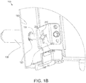
- Figure 1B is a perspective drawing of the latch apparatus 100.
- the latch pin 105 is shown passing through a center orifice 205 of the unit socket 155.
- the latch pin 105 may pass through the center orifice 205 of the unit socket 155 in an open position.
- the unit structure 155 further includes at least one polarized slot 210. Two polarized slots 210 are shown in the depicted embodiment.
- At least one latch wing (not shown) may pass through the polarized slot 210 as the latch pin 105 passes through the center orifice 205.
- the unit structure 155 further includes at least one wing indentation 215.
- the latch wing may be disposed in the wing indentation during the unit latch position. As a result, the latch wing may be obstructed from moving in the proximal direction 230 while the latch pin 105 is in the unit latch position.
- Figure 2A is a side view drawing of the latch pin 105,
- the latch pin 105 includes two latch wings 130.
- the latch wings 130 may be disposed within 0 to 5 centimeters of the pin distal end 125.
- Figure 2B is a side view drawing of an alternate embodiment of the latch pin 105.
- the latch pin 105 includes one latch wing 130.
- FIG. 2C is a front view drawing of an alternate embodiment of the latch pin 105.
- the latch pin 105 includes three latch wings 130.
- the latch pin 105 may include any number of latch wings 130.
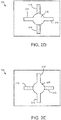
- Figure 2D is a front view drawing of the unit socket 155.
- the unit socket 155 includes the center orifice 205, two polarized slots 210, and two wing indentations 215.
- the center orifice 205 and the polarized slots 210 may permit the latch pin 105 and the latch wings 130 to pass through the unit socket 155 in the open position.
- the wing indentations 215 may receive the latch wings 130.
- the latch wings 130 may be biased into the wing indentations 215 by the biasing unit 140.
- Figure 2E is a front view drawing of the structure socket 160.
- the structure socket 160 includes the center orifice 205, two polarized slots 210, and two wing indentations 215.
- the polarized slots 210 of the structure socket 160 not are aligned with the polarized slots 210 of the unit structure 155 of Figure 2D .
- the latch pin 105 and the latch wings 130 may pass through the unit socket in the open position, the latch pin 105 and the latch wings 130 may not pass through the structure socket 160 in the open position.
- the polarized slots 210 of the structure socket 160 are aligned with the wing indentations 215 of the unit socket 155 of Figure 2D .
- the latch pin 105 and the latch wings 130 may pass through the structure socket 160 in the unit latch position.
- the latch pin 105 may further rotate to a structure latch position, wherein the latch wings 130 are biased into the wing indentations 215 of the structure socket 160.
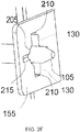
- Figure 2F is a perspective drawing of the unit socket 155.
- the latch pin 105 is in the open position.
- the latch pin 105 is shown passing through the center orifice 205.
- the latch wings 130 are shown passing through the polarized slots 210.
- Figure 2G is a front view drawing of the open position 250.
- the latch pin 105 is in the open position 250.
- the latch pin 105 may pass through the center orifice 205 and the latch wings 130 may pass through the polarized slots 210.
- Figure 2H is a front view drawing of the unit latch position 255 for the unit socket 155.
- the latch pin 105 of Figure 2G is rotated to the unit latch position 255.
- the latch wings 130 may be aligned with the wing indentations 215.
- the bias unit 140 may bias the latch wings 130 in the proximal direction 230 and into the wing indentations 215.
- the latch pin 105 is prevented from rotating from the unit latch position 255.
- the unit socket 155 obstructs the latch wing 130 from moving in the proximal direction 230 in the unit latch position 255.
- the latch pin 105 latches the equipment unit door 180 to the equipment unit 185 in the unit latch position 255. As a result, the equipment unit door 180 is securely latched to the equipment unit 185.
- Figure 2I is a front view drawing of the unit latch position 255 for the structure socket 160.
- the latch pin 105 of Figure 2H is in the unit latch position 255.
- the latch wings 130 may be aligned with the polarized slots 210 of the structure socket 160.
- the latch pin 105 may pass through the center orifice 205 and the latch wings 130 may pass through the polarized slots 210.
- the structure socket 160 passes the latch wing 130 in the unit latch position 255.
- FIG 2J is a front view drawing of the structure latch position 260 for the structure socket 160.
- the latch pin 105 of Figure 2I is rotated to the structure latch position 260.
- the latch wings 130 may be aligned with the wing indentations 215.
- the bias unit 140 may bias the latch wings 130 in the proximal direction 230 and into the wing indentations 215.
- the latch pin 105 may be prevented from rotating from the structure latch position 260.
- the socket structure 160 obstructs the latch wing 130 from moving in the proximal direction 230 in the structure latch position 260.
- the latch pin 105 may latch the equipment unit 185 to the structure in the structure latch position 260. As a result, the equipment unit 185 is securely latched to the structure.
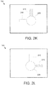
- Figure 2K is a front view drawing of an alternate embodiment of the unit socket 155.
- the unit socket 155 includes the central orifice 205, one polarized slot 210, and one wing indentation 215.
- the unit socket 155 may include any number of polarized slots 210 and wing indentations 215.
- FIG. 2L is a front view drawing of an alternate embodiment of the structure socket 160.
- the structure socket 160 includes the central orifice 205, one polarized slot 210, and one wing indentation 215.
- the polarized slot 210 of the structure socket 160 is aligned with the wing indentation 215 of the unit socket 155.
- the latch pin 105 may pass through the central orifice 205 and the latch wing 130 may pass through the polarized slot 210 of the structure socket 160 in the unit latch position 255.
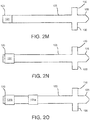
- Figure 2M is a side view drawing of the latch pin 105 with a position indicator 131.
- the latch pin 105 may comprise at least one position indicator 131.
- the position indicator 131 is a colored portion of the latch pin 105.
- the colored portion position indicator 131 may be viewed through an indicator hole to indicate the unit latch position 255 as will be described hereafter.
- the colored portion position indicator 131 may indicate the structure latch position 260.
- Figure 2N is a side view drawing of the latch pin 105 with the position indicator 131.
- the position indicator 131 is a colored sleeve that is disposed on the latch pin 105.
- the colored sleeve position indicator 131 may be viewed through the indicator hole to indicate the unit latch position 255 or the structure latch position 260 as will be described hereafter.
- Figure 2O is a side view drawing of the latch pin 105 with two position indicators 131a-b.
- the position indicators 131a-b are the colored sleeve.
- the first position indicator 131a may indicate the unit latch position 255 and the second position indicator 131b may indicate the structure latch position 260.
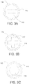
- Figure 3A is a front view drawing of the latch interface 115.
- the latch interface 115 is disposed within the sleeve 135.
- the latch interface 115 includes a rectangular indentation 116.
- the rectangular indentation 116 may receive a rotation tool such as a flat head screwdriver. The rotation tool may be fitted in the rectangular indentation 116 in order to rotate the latch pin 105 from the open position 250 to the unit latch position 255 and to the structure latch position 260.
- Figure 3B is a front view drawing of an alternative embodiment of the latch interface 155.
- the latch interface 155 is disposed within the sleeve 135.
- the latch interface 115 includes a cross indentation 117.
- the cross indentation 117 may receive a rotation tool such as a Phillips head screwdriver.
- the rotation tool may be fitted in the cross indentation 117 in order to rotate the latch pin 105 from the open position 250 to the unit latch position 255 and to the structure latch position 260.
- Figure 3C is a front view drawing of an alternative embodiment of the latch interface 155.
- the latch interface 155 is disposed within the sleeve 135.
- the latch interface 115 includes a hexagonal indentation 118.
- the hexagonal indentation 118 may receive a rotation tool such as a hex driver.
- the rotation tool may be fitted in the hexagonal indentation 218 and rotate the latch pin 105 from the open position 250 to the unit latch position 255 and to the structure latch position 260.
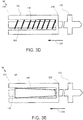
- Figure 3D is a schematic side view cutaway drawing of the latch apparatus 100.
- a spring biasing unit 140 is disposed within the sleeve 135.
- the spring biasing unit 140 may bias the latch pin 105 in the proximal direction 230.
- the sleeve 135 comprises a sleeve proximal end 240 and a sleeve distal end 235.
- the latch pin 105 is disposed within the sleeve 135.
- Figure 3E is a schematic side view cutaway drawing of an alternate embodiment of the latch apparatus 100.
- an elastic sleeve biasing unit 140 is disposed within the sleeve 135.
- the elastic sleeve biasing unit 140 may bias the latch pin 105 in the proximal direction 230.
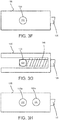
- Figure 3F is a schematic side view drawing of the sleeve 135 with an indicator hole 133.
- the sleeve 135 may include at least one indicator hole 133.
- the indicator hole 133 may allow the latch pin 105 to be viewed from outside of the sleeve 135.
- the position indicator 131 is visible through the indicator hole 133.
- the position indicator 131 is visible through the indicator hole 133 in the unit latch position 255.
- a user may ascertain that the latch pin 105 is in the unit latch position 255.
- the position indicator 131 is visible through the indicator hole 133 in the structure latch position 260.
- the user may ascertain that the latch pin 105 is in the structure latch position 260.
- the unit latch position indicator 131 is visible through the indicator hole 133 in the unit latch position 255.
- a structure latch position indicator 131 may be visible through the indicator hole 133 in the structure latch position 260.
- Figure 3G is a schematic side view cutaway drawing of the sleeve 135 with a position indicator 131 visible through the indicator hole 133.
- the position indicator 131 is shown disposed adjacent to the indicator hole 133.
- the position indicator 131 is visible through the indicator hole 133 and indicates to the user that the latch pin 105 is in one of the unit latch position 255 and the structure latch position 260.
- Figure 3H is a schematic side view drawing of the sleeve 135 with two indicator holes 133.
- the position indicator 131 is visible through a first indicator hole 133a, indicating that the latch pin 105 is in the unit latch position 255. If the position indicator 131 were visible through the second indicator hole 133b, the position indicator 131 would indicate that the latch pin 105 was in the structure latch position 260.
- FIG 4A is a perspective drawing illustrating one embodiment of the equipment unit 185.
- the equipment unit 185 includes a removal lever 181, the equipment unit door 180, and two sleeves 135 with latch pins 105 disposed within.
- the removal lever 181 may be used to extract the equipment unit 185 from a structure.
- the latch pins 105 may allow the equipment unit door 180 to be opened in the open position 250.
- the latch pins 105 may obstruct the equipment unit door 180 from being opened in the unit latch position 255.
- the equipment unit door 180 may only be opened if the latch pin 105 is in the open position 250.
- FIG 4B is a perspective drawing illustrating the equipment unit 185 disposed in the structure 170.
- the structure 170 may be an equipment rack, an equipment cabinet, and the like.
- the equipment unit 185 should not be removed from the structure 170 except when expressly desired by the user.
- the latch pins 105 may permit the equipment unit 185 to be removed from the structure 170 in the open position 250 and/or in the unit latch position 255.
- the equipment unit door 180 may not be opened in the unit latch position 255.
- the equipment unit 185 may be removed from the structure 170 while the equipment unit door 180 remains securely latched.
- the equipment unit 185 may not be removed from the structure 170 in the structure latch position 260.
- Figure 4C is a perspective drawing illustrating one embodiment of the structure 170 with the structure sockets 160.
- the structure sockets 160 are disposed on a structure bracket 225 and attached to the structure 170.
- Figure 5A is a schematic flow chart diagram illustrating one embodiment of a locking method 500.
- the method 500 may latch the equipment unit door 180 to the equipment unit 185 in the unit latch position 255.
- the method 500 may latch the equipment unit 185 to the structure 170.
- the method 500 starts, and in one embodiment, the latch pin 105 passes 505 in the open position 250 through the unit socket 155.
- the latch pin 105 may be pushed against the force of the biasing unit 140 through the unit socket 155.
- the latch pin 105 may further be rotated 510 to the unit latch position 255.
- the biasing unit 140 may bias the latch pin 105 in the proximal direction 230 such that the latch wings 130 are disposed in the wing indentations 215 of the unit socket 155.
- the latch pin 105 may be secured 515 in the unit latch position 255.
- the equipment unit door 180 may be securely latched to the equipment unit 185.
- the latch pin 105 may further pass 520 in the unit latch position 255 through the structure socket 160.
- the latch pin 105 may be rotated 525 to the structure latch position 260.
- the biasing unit 140 may bias the latch pin 105 in the proximal direction 230 such that the latch wings 130 are disposed in the wing indentations 215 of the structure socket 160.
- the latch pin 105 may be secured 530 in the structure latch position 260.
- the equipment unit 185 may be securely latched to the structure 170 and the method 500 ends.
- Figure 5B is a schematic flow chart diagram illustrating an unlocking method 600.
- the method 600 may unlatch the latching pin 105 from the structure latch position 260 and/or the unit latch position 255.
- the method 600 starts, and in one embodiment, the latch pin 105 is rotated 605 from the structure latch position 260 to the unit latch position 255. In one embodiment, the latch pin 105 is pushed opposite the proximal direction 230 so that the latch wings 130 disengage from the wing indentations 215 of the socket structure 160 and the latch pin 105 can be rotated 605.
- the latch pin 105 further passes 610 in the unit latch position 255 through the structure socket 160 in the proximal direction 230.
- the biasing unit 140 may push the latch pin 105 through the structure socket 160.
- the equipment unit 185 may be removed from the structure 170.
- the latch wings 130 come to rest with in the wing indentations 215 of the unit structure 155.
- the latch pin 105 may further rotate 615 to the open position 250.
- the latch pin 105 is pushed opposite the proximal direction 230 so that the latch wings 130 disengage from the wing indentations 215 of the unit socket 160 and the latch pin 105 can be rotated 615.
- the latch pin 105 passes 620 in the open position 250 through the unit socket 155.
- the biasing unit 140 may push the latch pin 105 through the unit socket 155.
- the equipment unit door 180 may be opened.
- the equipment unit 185 may be removed from the structure 170 and the method 600 ends.
- Equipment units 185 often include internal hardware that is dangerous to users.
- the internal hardware may include strong electrical currents, high voltages, moving parts, and the like.
- the equipment unit door 180 should be securely latched so that no user is inadvertently exposed to the internal hardware.
- qualified users must often access the internal hardware within the equipment unit 185 such as to perform diagnostics or repairs. Therefore, the equipment unit door 180 must be readily unlatched when access is needed.
- the equipment unit 185 may be disposed in a structure 170. The equipment unit 185 should typically be latched to the structure 170 so that the equipment unit 185 is not inadvertently removed from the structure.
- the embodiments allow a latch pin 105 to both securely latch the equipment unit door 180 to the equipment unit 185 and secure latch the equipment unit 180 to the structure 170. So latched in the unit latch position 255, the equipment unit door 185 cannot be opened without moving the latch pin 105 to the open position 250. In addition, the equipment unit 185 cannot be removed from the structure 170 while the latch pin 105 is in the structure latch position 260. The equipment unit 185 can only be removed from the structure 170 by rotating the latch pin 105 to the unit latch position 255. Thus, the latch pin 105 both latches the equipment unit door 180 to the equipment unit 185 and latches the equipment unit 185 to the structure 170.
Landscapes
- Engineering & Computer Science (AREA)
- Microelectronics & Electronic Packaging (AREA)
- Mechanical Engineering (AREA)
- Casings For Electric Apparatus (AREA)
- Details Of Connecting Devices For Male And Female Coupling (AREA)
- Infusion, Injection, And Reservoir Apparatuses (AREA)
Abstract
Description
- The subject matter disclosed herein relates to latching an equipment unit door for a control center.
- An apparatus for latching an equipment unit door of an equipment unit in a control center is disclosed. The apparatus includes a latch pin, the unit socket, and a structure socket. The latch pin includes a latch shaft with a latch interface disposed on a pin proximal end and a latch wing disposed on a pin distal end. The latch pin rotates to one of an open position, a unit latch position, and a structure latch position. The unit socket passes the latch wing in the open position and obstructs the latch wing from moving in a proximal direction in the unit latch position. The structure socket passes the latch wing in the unit latch position and obstructs the latch wing from moving in the proximal direction in the structure latch position.
- A system for latching an equipment unit door of an equipment unit in a control center is also disclosed. The system includes a structure, the equipment unit, a latch pin, the unit socket, and a structure socket. The latch pin includes a latch shaft with a latch interface disposed on a pin proximal end and a latch wing disposed on a pin distal end. The latch pin rotates to one of an open position, a unit latch position, and a structure latch position. The unit socket passes the latch wing in the open position and obstructs the latch wing from moving in a proximal direction in the unit latch position. The structure socket passes the latch wing in the unit latch position and obstructs the latch wing from moving in the proximal direction in the structure latch position.
- A method for latching an equipment door of an equipment unit in a control center is also disclosed. The method passes the latch pin in an open position through a unit socket. The latch pin includes a latch shaft and a latch interface disposed on a pin proximal end and the latch wing disposed on a pin distal end. The latch pin rotates to one of an open position, a unit latch position, and a structure latch position. The method further rotates the latch pin to the unit latch position. The unit socket obstructs the latch wing from moving in a proximal direction in the unit latch position.
- In order that the advantages of the embodiments of the invention will be readily understood, a more particular description of the embodiments briefly described above will be rendered by reference to specific embodiments that are illustrated in the appended drawings. Understanding that these drawings depict only some embodiments and are not therefore to be considered to be limiting of scope, the embodiments will be described and explained with additional specificity and detail through the use of the accompanying drawings, in which:
-
Figure 1A is a perspective drawing of an equipment unit with latch apparatus according to an embodiment; -
Figure 1B is a perspective drawing of a latch apparatus according to an embodiment; -
Figure 2A is a side view drawing of a latch pin according to an embodiment; -
Figure 2B is a side view drawing of a latch pin according to an alternate embodiment; -
Figure 2C is a front view drawing of a latch pin according to an alternate embodiment; -
Figure 2D is a front view drawing of the unit socket according to an embodiment; -
Figure 2E is a front view drawing of a structure socket according to an embodiment; -
Figure 2F is a perspective drawing of a unit socket according to an embodiment; -
Figure 2G is a front view drawing of an open position according to an embodiment; -
Figure 2H is a front view drawing of a unit latch position for a unit socket according to an embodiment; -
Figure 2I is a front view drawing of a unit latch position for a structure socket according to an embodiment; -
Figure 2J is a front view drawing of a structure latch position for a structure socket according to an embodiment; -
Figure 2K is a front view drawing of a unit socket according to an alternate embodiment; -
Figure 2L is a front view drawing of a structure socket according to an alternative embodiment; -
Figure 2M is a side view drawing of a latch pin with position indicator according to an embodiment; -
Figure 2N is a side view drawing of a latch pin with position indicator according to an alternative embodiment; -
Figure 2O is a side view drawing of a latch pin with position indicators according to an alternative embodiment; -
Figure 3A is a front view drawing of a latch interface according to an embodiment; -
Figure 3B is a front view drawing of a latch interface according to an alternative embodiment; -
Figure 3C is a front view drawing of a latch interface according to an alternative embodiment; -
Figure 3D is a schematic side view cutaway drawing of a latch apparatus with biasing unit according to an embodiment; -
Figure 3E is a schematic side view cutaway drawing of a latch apparatus with biasing unit according to an alternate embodiment; -
Figure 3F is a schematic side view drawing of a sleeve with an indicator hole according to an embodiment; -
Figure 3G is a schematic side view cutaway drawing of a sleeve with an indicator hole and position indicator according to an embodiment; -
Figure 3H is a schematic side view drawing of a sleeve with two indicator holes according to an embodiment; -
Figure 4A is a perspective drawing illustrating an equipment unit according to an embodiment; -
Figure 4B is a perspective drawing illustrating a structure with an equipment unit according to an embodiment; -
Figure 4C is a perspective drawing illustrating a structure with structure sockets according to an embodiment; -
Figure 5A is a schematic flow chart diagram illustrating a locking method according to an embodiment; and -
Figure 5B is a schematic flow chart diagram illustrating an unlocking method according to an embodiment. - Reference throughout this specification to "one embodiment," "an embodiment," or similar language means that a particular feature, structure, or characteristic described in connection with the embodiment is included in at least one embodiment. Thus, appearances of the phrases "in one embodiment," "in an embodiment," and similar language throughout this specification may, but do not necessarily, all refer to the same embodiment, but mean "one or more but not all embodiments" unless expressly specified otherwise. The terms "including," "comprising," "having," and variations thereof mean "including but not limited to" unless expressly specified otherwise. An enumerated listing of items does not imply that any or all of the items are mutually exclusive and/or mutually inclusive, unless expressly specified otherwise. The terms "a," "an," and "the" also refer to "one or more" unless expressly specified otherwise.
- The schematic flowchart diagrams and/or schematic block diagrams in the Figures illustrate the architecture, functionality, and operation of possible implementations. It should also be noted that, in some alternative implementations, the functions noted in the block may occur out of the order noted in the Figures. For example, two blocks shown in succession may, in fact, be executed substantially concurrently, or the blocks may sometimes be executed in the reverse order, depending upon the functionality involved. Although various arrow types and line types may be employed in the flowchart and/or block diagrams, they are understood not to limit the scope of the corresponding embodiments. Indeed, some arrows or other connectors may be used to indicate only an exemplary logical flow of the depicted embodiment.
- The description of elements in each figure may refer to elements of proceeding figures. Like numbers refer to like elements in all figures, including alternate embodiments of like elements.
-
Figure 1A is a perspective drawing of anequipment unit 185. Theequipment unit 185 may reside in a control center. In one embodiment, theequipment unit 185 is disposed within a structure such as a rack, cabinet, and the like in the control center. Theequipment unit 185 may house internal hardware (not shown) such as motor controllers, inverters, converters, power regulators, data processing hardware, and the like. Theequipment unit 185 includes anequipment unit door 180. The internal hardware may be accessible by opening theequipment unit door 180. However, because the internal hardware may pose a safety risk, theequipment unit door 180 should be securely latched so that no user is inadvertently exposed to the internal hardware. In addition, theequipment unit 185 may be disposed in a structure. Theequipment unit 185 should be latched to the structure so that theequipment unit 185 is not inadvertently removed from the structure. - The embodiments described herein securely latch the
equipment unit door 180 to theequipment unit 185. In addition, the embodiments may securely latch theequipment unit 185 to the structure. In the depicted embodiment, theapparatus 100 includes alatch pin 105. Thelatch pin 105 may include alatch shaft 110 with alatch interface 115. Thelatch interface 115 may be disposed on a pinproximal end 120 of thelatch pin 105. Thelatch pin 105 may further include a latch wing (not shown). The latch wing may be disposed on a pindistal end 125 of thelatch pin 105. Thelatch pin 105 may rotate to one of an open position and a structure latch position as will be described hereafter. Thelatch pin 105 may latch theequipment unit door 180 to theequipment unit 185 in the unit latch position. - In one embodiment, the latch apparatus further includes a
sleeve 135. Thelatch pin 105 may be disposed within thesleeve 135. A sleevedistal end 235 may be connected to theequipment door 180. In addition, the latch apparatus may include abiasing unit 140. In the depicted embodiment, the biasingunit 140 is a spring. The biasingunit 140 may bias the latch pin in aproximal direction 230 toward a sleeveproximal end 240. The biasingunit 140 may be selected from the group consisting of a coil spring, an elastic sleeve, and a torsion flange. - The latch apparatus may further include a
unit socket 155. Theunit socket 155 may be connected to theequipment unit 185. Theunit socket 155 may be disposed on aunit bracket 220 and attached to theequipment unit 185. The latching of thelatch pin 105 to theunit socket 155 and the structure socket will be described hereafter. -
Figure 1B is a perspective drawing of thelatch apparatus 100. In the depicted embodiment, thelatch pin 105 is shown passing through acenter orifice 205 of theunit socket 155. Thelatch pin 105 may pass through thecenter orifice 205 of theunit socket 155 in an open position. Theunit structure 155 further includes at least onepolarized slot 210. Twopolarized slots 210 are shown in the depicted embodiment. At least one latch wing (not shown) may pass through thepolarized slot 210 as thelatch pin 105 passes through thecenter orifice 205. - The
unit structure 155 further includes at least onewing indentation 215. The latch wing may be disposed in the wing indentation during the unit latch position. As a result, the latch wing may be obstructed from moving in theproximal direction 230 while thelatch pin 105 is in the unit latch position. -
Figure 2A is a side view drawing of thelatch pin 105, In the depicted embodiment, thelatch pin 105 includes twolatch wings 130. Thelatch wings 130 may be disposed within 0 to 5 centimeters of the pindistal end 125. -
Figure 2B is a side view drawing of an alternate embodiment of thelatch pin 105. In the depicted embodiment, thelatch pin 105 includes onelatch wing 130. -
Figure 2C is a front view drawing of an alternate embodiment of thelatch pin 105. In the depicted embodiment, thelatch pin 105 includes threelatch wings 130. Thelatch pin 105 may include any number oflatch wings 130. -
Figure 2D is a front view drawing of theunit socket 155. In the depicted embodiment, theunit socket 155 includes thecenter orifice 205, twopolarized slots 210, and twowing indentations 215. In one embodiment, there is onepolarized slot 210 and onewing indentation 215 for eachlatch wing 130. Thecenter orifice 205 and thepolarized slots 210 may permit thelatch pin 105 and thelatch wings 130 to pass through theunit socket 155 in the open position. - If the
latch pin 105 rotates to the unit latch position, thewing indentations 215 may receive thelatch wings 130. In one embodiment, thelatch wings 130 may be biased into thewing indentations 215 by the biasingunit 140. -
Figure 2E is a front view drawing of thestructure socket 160. In the depicted embodiment, thestructure socket 160 includes thecenter orifice 205, twopolarized slots 210, and twowing indentations 215. In one embodiment, there is onepolarized slot 210 and onewing indentation 215 for eachlatch wing 130. - In the depicted embodiment, the
polarized slots 210 of thestructure socket 160 not are aligned with thepolarized slots 210 of theunit structure 155 ofFigure 2D . As a result, while thelatch pin 105 and thelatch wings 130 may pass through the unit socket in the open position, thelatch pin 105 and thelatch wings 130 may not pass through thestructure socket 160 in the open position. - In addition, in the depicted embodiment, the
polarized slots 210 of thestructure socket 160 are aligned with thewing indentations 215 of theunit socket 155 ofFigure 2D . As a result, thelatch pin 105 and thelatch wings 130 may pass through thestructure socket 160 in the unit latch position. Thelatch pin 105 may further rotate to a structure latch position, wherein thelatch wings 130 are biased into thewing indentations 215 of thestructure socket 160. -
Figure 2F is a perspective drawing of theunit socket 155. In the depicted embodiment, thelatch pin 105 is in the open position. Thelatch pin 105 is shown passing through thecenter orifice 205. In addition, thelatch wings 130 are shown passing through thepolarized slots 210. -
Figure 2G is a front view drawing of theopen position 250. In the depicted embodiment, thelatch pin 105 is in theopen position 250. As shown inFigure 2F , thelatch pin 105 may pass through thecenter orifice 205 and thelatch wings 130 may pass through thepolarized slots 210. -
Figure 2H is a front view drawing of theunit latch position 255 for theunit socket 155. In the depicted embodiment, thelatch pin 105 ofFigure 2G is rotated to theunit latch position 255. In theunit latch position 255, thelatch wings 130 may be aligned with thewing indentations 215. Thebias unit 140 may bias thelatch wings 130 in theproximal direction 230 and into thewing indentations 215. In one embodiment, with thelatch wings 130 disposed in thewing indentations 215, thelatch pin 105 is prevented from rotating from theunit latch position 255. Thus, theunit socket 155 obstructs thelatch wing 130 from moving in theproximal direction 230 in theunit latch position 255. Thelatch pin 105 latches theequipment unit door 180 to theequipment unit 185 in theunit latch position 255. As a result, theequipment unit door 180 is securely latched to theequipment unit 185. -
Figure 2I is a front view drawing of theunit latch position 255 for thestructure socket 160. In the depicted embodiment, thelatch pin 105 ofFigure 2H is in theunit latch position 255. In theunit latch position 255, thelatch wings 130 may be aligned with thepolarized slots 210 of thestructure socket 160. Thelatch pin 105 may pass through thecenter orifice 205 and thelatch wings 130 may pass through thepolarized slots 210. Thus, thestructure socket 160 passes thelatch wing 130 in theunit latch position 255. -
Figure 2J is a front view drawing of thestructure latch position 260 for thestructure socket 160. In the depicted embodiment, thelatch pin 105 ofFigure 2I is rotated to thestructure latch position 260. In the structure latch position, thelatch wings 130 may be aligned with thewing indentations 215. Thebias unit 140 may bias thelatch wings 130 in theproximal direction 230 and into thewing indentations 215. With thelatch wings 130 disposed in thewing indentations 215, thelatch pin 105 may be prevented from rotating from thestructure latch position 260. Thus, thesocket structure 160 obstructs thelatch wing 130 from moving in theproximal direction 230 in thestructure latch position 260. Thelatch pin 105 may latch theequipment unit 185 to the structure in thestructure latch position 260. As a result, theequipment unit 185 is securely latched to the structure. -
Figure 2K is a front view drawing of an alternate embodiment of theunit socket 155. In the depicted embodiment, theunit socket 155 includes thecentral orifice 205, onepolarized slot 210, and onewing indentation 215. Theunit socket 155 may include any number ofpolarized slots 210 andwing indentations 215. -
Figure 2L is a front view drawing of an alternate embodiment of thestructure socket 160. In the depicted embodiment, thestructure socket 160 includes thecentral orifice 205, onepolarized slot 210, and onewing indentation 215. Thepolarized slot 210 of thestructure socket 160 is aligned with thewing indentation 215 of theunit socket 155. As a result, thelatch pin 105 may pass through thecentral orifice 205 and thelatch wing 130 may pass through thepolarized slot 210 of thestructure socket 160 in theunit latch position 255. -
Figure 2M is a side view drawing of thelatch pin 105 with aposition indicator 131. Thelatch pin 105 may comprise at least oneposition indicator 131. In the depicted embodiment, theposition indicator 131 is a colored portion of thelatch pin 105. The coloredportion position indicator 131 may be viewed through an indicator hole to indicate theunit latch position 255 as will be described hereafter. In addition, the coloredportion position indicator 131 may indicate thestructure latch position 260. -
Figure 2N is a side view drawing of thelatch pin 105 with theposition indicator 131. In the depicted embodiment, theposition indicator 131 is a colored sleeve that is disposed on thelatch pin 105. The coloredsleeve position indicator 131 may be viewed through the indicator hole to indicate theunit latch position 255 or thestructure latch position 260 as will be described hereafter. -
Figure 2O is a side view drawing of thelatch pin 105 with twoposition indicators 131a-b. In the depicted embodiment, theposition indicators 131a-b are the colored sleeve. Thefirst position indicator 131a may indicate theunit latch position 255 and thesecond position indicator 131b may indicate thestructure latch position 260. -
Figure 3A is a front view drawing of thelatch interface 115. In the depicted embodiment, thelatch interface 115 is disposed within thesleeve 135. Thelatch interface 115 includes arectangular indentation 116. Therectangular indentation 116 may receive a rotation tool such as a flat head screwdriver. The rotation tool may be fitted in therectangular indentation 116 in order to rotate thelatch pin 105 from theopen position 250 to theunit latch position 255 and to thestructure latch position 260. -
Figure 3B is a front view drawing of an alternative embodiment of thelatch interface 155. In the depicted embodiment, thelatch interface 155 is disposed within thesleeve 135. Thelatch interface 115 includes across indentation 117. Thecross indentation 117 may receive a rotation tool such as a Phillips head screwdriver. The rotation tool may be fitted in thecross indentation 117 in order to rotate thelatch pin 105 from theopen position 250 to theunit latch position 255 and to thestructure latch position 260. -
Figure 3C is a front view drawing of an alternative embodiment of thelatch interface 155. In the depicted embodiment, thelatch interface 155 is disposed within thesleeve 135. Thelatch interface 115 includes ahexagonal indentation 118. Thehexagonal indentation 118 may receive a rotation tool such as a hex driver. The rotation tool may be fitted in the hexagonal indentation 218 and rotate thelatch pin 105 from theopen position 250 to theunit latch position 255 and to thestructure latch position 260. -
Figure 3D is a schematic side view cutaway drawing of thelatch apparatus 100. In the depicted embodiment, aspring biasing unit 140 is disposed within thesleeve 135. Thespring biasing unit 140 may bias thelatch pin 105 in theproximal direction 230. Thesleeve 135 comprises a sleeveproximal end 240 and a sleevedistal end 235. Thelatch pin 105 is disposed within thesleeve 135. -
Figure 3E is a schematic side view cutaway drawing of an alternate embodiment of thelatch apparatus 100. In the depicted embodiment, an elasticsleeve biasing unit 140 is disposed within thesleeve 135. The elasticsleeve biasing unit 140 may bias thelatch pin 105 in theproximal direction 230. -
Figure 3F is a schematic side view drawing of thesleeve 135 with anindicator hole 133. Thesleeve 135 may include at least oneindicator hole 133. Theindicator hole 133 may allow thelatch pin 105 to be viewed from outside of thesleeve 135. In the depicted embodiment, theposition indicator 131 is visible through theindicator hole 133. In one embodiment, theposition indicator 131 is visible through theindicator hole 133 in theunit latch position 255. As a result, a user may ascertain that thelatch pin 105 is in theunit latch position 255. In an alternate embodiment, theposition indicator 131 is visible through theindicator hole 133 in thestructure latch position 260. As a result, the user may ascertain that thelatch pin 105 is in thestructure latch position 260. - In one embodiment, the unit
latch position indicator 131 is visible through theindicator hole 133 in theunit latch position 255. In addition, a structurelatch position indicator 131 may be visible through theindicator hole 133 in thestructure latch position 260. -
Figure 3G is a schematic side view cutaway drawing of thesleeve 135 with aposition indicator 131 visible through theindicator hole 133. In the depicted embodiment, theposition indicator 131 is shown disposed adjacent to theindicator hole 133. As a result, theposition indicator 131 is visible through theindicator hole 133 and indicates to the user that thelatch pin 105 is in one of theunit latch position 255 and thestructure latch position 260. -
Figure 3H is a schematic side view drawing of thesleeve 135 with two indicator holes 133. In the depicted embodiment, theposition indicator 131 is visible through afirst indicator hole 133a, indicating that thelatch pin 105 is in theunit latch position 255. If theposition indicator 131 were visible through thesecond indicator hole 133b, theposition indicator 131 would indicate that thelatch pin 105 was in thestructure latch position 260. -
Figure 4A is a perspective drawing illustrating one embodiment of theequipment unit 185. In the depicted embodiment, theequipment unit 185 includes aremoval lever 181, theequipment unit door 180, and twosleeves 135 withlatch pins 105 disposed within. Theremoval lever 181 may be used to extract theequipment unit 185 from a structure. The latch pins 105 may allow theequipment unit door 180 to be opened in theopen position 250. In addition, the latch pins 105 may obstruct theequipment unit door 180 from being opened in theunit latch position 255. Theequipment unit door 180 may only be opened if thelatch pin 105 is in theopen position 250. -
Figure 4B is a perspective drawing illustrating theequipment unit 185 disposed in thestructure 170. Thestructure 170 may be an equipment rack, an equipment cabinet, and the like. Theequipment unit 185 should not be removed from thestructure 170 except when expressly desired by the user. The latch pins 105 may permit theequipment unit 185 to be removed from thestructure 170 in theopen position 250 and/or in theunit latch position 255. However, theequipment unit door 180 may not be opened in theunit latch position 255. As a result, theequipment unit 185 may be removed from thestructure 170 while theequipment unit door 180 remains securely latched. Theequipment unit 185 may not be removed from thestructure 170 in thestructure latch position 260. -
Figure 4C is a perspective drawing illustrating one embodiment of thestructure 170 with thestructure sockets 160. In the depicted embodiment, thestructure sockets 160 are disposed on astructure bracket 225 and attached to thestructure 170. -
Figure 5A is a schematic flow chart diagram illustrating one embodiment of alocking method 500. Themethod 500 may latch theequipment unit door 180 to theequipment unit 185 in theunit latch position 255. In addition, themethod 500 may latch theequipment unit 185 to thestructure 170. - The
method 500 starts, and in one embodiment, thelatch pin 105 passes 505 in theopen position 250 through theunit socket 155. Thelatch pin 105 may be pushed against the force of thebiasing unit 140 through theunit socket 155. - The
latch pin 105 may further be rotated 510 to theunit latch position 255. In one embodiment, the biasingunit 140 may bias thelatch pin 105 in theproximal direction 230 such that thelatch wings 130 are disposed in thewing indentations 215 of theunit socket 155. As a result, thelatch pin 105 may be secured 515 in theunit latch position 255. With thelatch pin 105 secured 515 in theunit latch position 255, theequipment unit door 180 may be securely latched to theequipment unit 185. - The
latch pin 105 may further pass 520 in theunit latch position 255 through thestructure socket 160. Thelatch pin 105 may be rotated 525 to thestructure latch position 260. The biasingunit 140 may bias thelatch pin 105 in theproximal direction 230 such that thelatch wings 130 are disposed in thewing indentations 215 of thestructure socket 160. As a result, thelatch pin 105 may be secured 530 in thestructure latch position 260. With thelatch pin 105 secured 530 in thestructure latch position 260, theequipment unit 185 may be securely latched to thestructure 170 and themethod 500 ends. -
Figure 5B is a schematic flow chart diagram illustrating an unlockingmethod 600. Themethod 600 may unlatch thelatching pin 105 from thestructure latch position 260 and/or theunit latch position 255. - The
method 600 starts, and in one embodiment, thelatch pin 105 is rotated 605 from thestructure latch position 260 to theunit latch position 255. In one embodiment, thelatch pin 105 is pushed opposite theproximal direction 230 so that thelatch wings 130 disengage from thewing indentations 215 of thesocket structure 160 and thelatch pin 105 can be rotated 605. - The
latch pin 105further passes 610 in theunit latch position 255 through thestructure socket 160 in theproximal direction 230. The biasingunit 140 may push thelatch pin 105 through thestructure socket 160. As a result, theequipment unit 185 may be removed from thestructure 170. - In one embodiment, the
latch wings 130 come to rest with in thewing indentations 215 of theunit structure 155. Thelatch pin 105 may further rotate 615 to theopen position 250. In one embodiment, thelatch pin 105 is pushed opposite theproximal direction 230 so that thelatch wings 130 disengage from thewing indentations 215 of theunit socket 160 and thelatch pin 105 can be rotated 615. - The
latch pin 105 passes 620 in theopen position 250 through theunit socket 155. The biasingunit 140 may push thelatch pin 105 through theunit socket 155. As a result, theequipment unit door 180 may be opened. In addition, theequipment unit 185 may be removed from thestructure 170 and themethod 600 ends. -
Equipment units 185 often include internal hardware that is dangerous to users. The internal hardware may include strong electrical currents, high voltages, moving parts, and the like. As a result, theequipment unit door 180 should be securely latched so that no user is inadvertently exposed to the internal hardware. However, qualified users must often access the internal hardware within theequipment unit 185 such as to perform diagnostics or repairs. Therefore, theequipment unit door 180 must be readily unlatched when access is needed. In addition, theequipment unit 185 may be disposed in astructure 170. Theequipment unit 185 should typically be latched to thestructure 170 so that theequipment unit 185 is not inadvertently removed from the structure. - The embodiments allow a
latch pin 105 to both securely latch theequipment unit door 180 to theequipment unit 185 and secure latch theequipment unit 180 to thestructure 170. So latched in theunit latch position 255, theequipment unit door 185 cannot be opened without moving thelatch pin 105 to theopen position 250. In addition, theequipment unit 185 cannot be removed from thestructure 170 while thelatch pin 105 is in thestructure latch position 260. Theequipment unit 185 can only be removed from thestructure 170 by rotating thelatch pin 105 to theunit latch position 255. Thus, thelatch pin 105 both latches theequipment unit door 180 to theequipment unit 185 and latches theequipment unit 185 to thestructure 170. - This description uses examples to disclose the invention and also to enable any person skilled in the art to practice the invention, including making and using any devices or systems and performing any incorporated methods. The patentable scope of the invention is defined by the claims and may include other examples that occur to those skilled in the art. Such other examples are intended to be within the scope of the claims if they have structural elements that do not differ from the literal language of the claims, or if they include equivalent structural elements with insubstantial differences from the literal language of the claims.
Claims (15)
- An apparatus comprising:a latch pin 105 comprising a latch shaft 110 with a latch interface 115 disposed on a pin proximal end 120 and a latch wing 130 disposed on a pin distal end 125, wherein the latch pin 105 rotates to one of an open position 250, a unit latch position 255, and a structure latch position 260;a unit socket 155 that passes the latch wing 130 in the open position, and that obstructs the latch wing 130 from moving in a proximal direction 230 in the unit latch position 255; anda structure socket 160 that passes the latch wing 130 in the unit latch position, and that obstructs the latch wing 130 from moving in the proximal direction 230 in the structure latch position 260.
- The apparatus of claim 1, wherein the latch pin 105 latches an equipment unit door 180 to an equipment unit 185 in the unit latch position 255; and/or
wherein the latch pin 105 latches an equipment unit door 180 to an equipment unit 185 in the unit latch position and latches the equipment unit 185 to a structure 170 in the structure latch position 260. - The apparatus of claim 1 or 2, the apparatus further comprising a sleeve 135 comprising a sleeve proximal end 240 and a sleeve distal end 235, wherein the latch pin 105 is disposed within the sleeve 135.
- The apparatus of claim 3, wherein the sleeve distal end 235 is connected to an equipment unit door 180.
- The apparatus of claim 4, the apparatus further comprising a biasing unit 140 that biases the latch pin 105 toward the sleeve proximal end 240, and wherein the biasing unit 140 is selected from the group consisting of a coil spring, an elastic sleeve, and a torsion flange.
- The apparatus of claim 3, wherein the latch pin 105 comprises at least one position indicator 131, the sleeve 135 comprises an indicator hole 133, and a unit latch position indicator 131 is visible through the indicator hole 133 in the unit latch position 255 and a structure latch position indicator 131 is visible through the indicator hole 133 in the structure latch position 260.
- The apparatus of one of claims 1 to 6, wherein at least one of:the unit socket 155 and the structure socket 160 each comprise a center orifice 205 that the latch pin 105 passes through, a polarized slot 210 that the latch wing 130 passes through, and a wing indentation 215 that the latch wing 130 is disposed within during one of the unit latch position 255 and the structure latch position 260;the unit socket 155 is disposed on a unit bracket 220 and is attached to an equipment unit 185; andthe structure socket 160 is disposed on a structure bracket 225 and is attached to a structure 170.
- A system comprising:a structure 170an equipment unit 185 disposed in the structure 170 and comprising an equipment unit door 180;a latch pin 105 comprising a latch shaft 110 with a latch interface 115 disposed on a pin proximal end 120 and a latch wing 130 disposed on a pin distal end 125, wherein the latch pin 105 rotates to one of an open position 250, a unit latch position 255, and a structure latch position 260;a unit socket 155 that passes the latch wing 130 in the open position, and that obstructs the latch wing 130 from moving in a proximal direction 230 in the unit latch position 255, wherein the latch pin 105 latches the equipment unit door 180 to the equipment unit 185 in the unit latch position 255; anda structure socket 160 that passes the latch wing 130 in the unit latch position, and that obstructs the latch wing 130 from moving in the proximal direction 230 in the structure latch position 260.
- The system of claim 8, wherein the latch pin 105 latches the equipment unit 185 to the structure 170 in the structure latch position 260.
- The system of claim 8 or 9, the system further comprising a sleeve 135 comprising a sleeve proximal end 240 and a sleeve distal end 235, wherein the latch pin 105 is disposed within the sleeve 135.
- The system of claim 10, wherein the sleeve distal end 235 is connected to the equipment unit door 180.
- The system of claim 11, the apparatus further comprising a biasing unit 140 that biases the latch pin 105 toward the sleeve proximal end 240, and wherein the biasing unit 140 is selected from the group consisting of a coil spring, an elastic sleeve, and a torsion flange.
- The system of claim 10, wherein the latch pin 105 comprises at least one position indicator 131, the sleeve 135 comprises an indicator hole 133, and a unit latch position indicator 131 is visible through the indicator hole 133 in the unit latch position 255 and a structure latch position indicator 131 is visible through the indicator hole 133 in the structure latch position 260.
- The system of claim 11, wherein at least one of:the unit socket 155 and the structure socket 160 each comprise a center orifice 205 that the latch pin 105 passes through, a polarized slot 210 that the latch wing 130 passes through, and a wing indentation 215 that the latch wing 130 is disposed within during one of the unit latch position 255 and the structure latch position 260;the unit socket 155 is disposed on a unit bracket 220 and is attached to the equipment unit 185; andthe structure socket 160 is disposed on a structure bracket 225 and is attached to the structure 170.
- A method comprising:passing a latch pin 105 in an open position 250 through a unit socket 155, the latch pin 155 comprising a latch shaft 110 with a latch interface 115 disposed on a pin proximal end 120 and a latch wing 130 disposed on a pin distal end 125, wherein the latch pin 105 rotates to one of the open position 250 and a unit latch position 255; androtating the latch pin 105 to the unit latch position 255, wherein the unit socket 155 obstructs the latch wing 130 from moving in a proximal direction 230 in the unit latch position 255.
Applications Claiming Priority (1)
| Application Number | Priority Date | Filing Date | Title |
|---|---|---|---|
| US15/824,714 US10837207B2 (en) | 2017-11-28 | 2017-11-28 | Control center door latch |
Publications (2)
| Publication Number | Publication Date |
|---|---|
| EP3489438A1 true EP3489438A1 (en) | 2019-05-29 |
| EP3489438B1 EP3489438B1 (en) | 2020-07-15 |
Family
ID=64500162
Family Applications (1)
| Application Number | Title | Priority Date | Filing Date |
|---|---|---|---|
| EP18208238.8A Active EP3489438B1 (en) | 2017-11-28 | 2018-11-26 | Control center door latch |
Country Status (3)
| Country | Link |
|---|---|
| US (1) | US10837207B2 (en) |
| EP (1) | EP3489438B1 (en) |
| CN (1) | CN110318582B (en) |
Families Citing this family (3)
| Publication number | Priority date | Publication date | Assignee | Title |
|---|---|---|---|---|
| DE102018221151A1 (en) * | 2018-12-06 | 2020-06-10 | Siemens Mobility GmbH | Secured equipment carrier holding device |
| US12221810B2 (en) * | 2021-07-09 | 2025-02-11 | Hoffman Enclosures Inc. | Apparatus and methods for securing an equipment cabinet |
| US12598713B2 (en) * | 2023-12-26 | 2026-04-07 | Dish Network L.L.C. | Method and apparatus for opening a receiving device |
Citations (6)
| Publication number | Priority date | Publication date | Assignee | Title |
|---|---|---|---|---|
| FR687615A (en) * | 1930-01-03 | 1930-08-11 | Lock | |
| AU495036B2 (en) * | 1973-05-03 | 1975-11-06 | Scallan, J.P. | Latch mechanism |
| GB2219032A (en) * | 1988-05-27 | 1989-11-29 | Granfit Holdings Limited | Fastening with axially movable bolt indicating |
| US6170304B1 (en) * | 1999-02-26 | 2001-01-09 | Hewlett-Packard Company | Method and apparatus for securing electronic components |
| WO2002092443A2 (en) * | 2001-05-16 | 2002-11-21 | Cotswold Design And Consultancy Limited | Modular box |
| US20070085347A1 (en) * | 2005-10-13 | 2007-04-19 | Malkowski Chester Jr | Arc resistant electrical enclosure system and method |
Family Cites Families (47)
| Publication number | Priority date | Publication date | Assignee | Title |
|---|---|---|---|---|
| US1603159A (en) * | 1922-02-01 | 1926-10-12 | Albert J Snyder | Sash fastener |
| US1531901A (en) * | 1923-09-08 | 1925-03-31 | Frank D Clark | Lock for window sash |
| US1714196A (en) * | 1926-09-03 | 1929-05-21 | Joseph C Vara | Sash fastener |
| US1672333A (en) | 1927-05-12 | 1928-06-05 | Roy Peters | License-plate holder |
| US1792537A (en) * | 1927-10-28 | 1931-02-17 | Curtiss Aeroplane & Motor Co | Cowl fastener |
| US1737891A (en) * | 1927-12-29 | 1929-12-03 | George L Parkins | Window fastener |
| BE434446A (en) * | 1938-01-14 | 1900-01-01 | ||
| US2631877A (en) * | 1950-07-28 | 1953-03-17 | Ainsworth Mark | Lockable slide bolt assembly for doors and the like |
| FR1026519A (en) | 1950-10-25 | 1953-04-28 | Const Aeronautiques Du Soud Ou | Removable locking connection device for mechanical parts |
| US2831520A (en) * | 1954-07-20 | 1958-04-22 | Northrop Aircraft Inc | Telescoping captive screw holder with stop means for screw |
| US2877637A (en) * | 1956-03-14 | 1959-03-17 | Greenwald Co Inc H | Locked coin drawer |
| US3136017A (en) * | 1961-08-01 | 1964-06-09 | Elastic Stop Nut Corp | Fastening device |
| US3179457A (en) * | 1962-02-05 | 1965-04-20 | Camloc Fastener Corp | Readily releasable fastener |
| DE1871657U (en) * | 1962-09-28 | 1963-05-09 | Siemens Ag | ASSEMBLY ARRANGEMENT. |
| GB1136662A (en) | 1966-04-23 | 1968-12-11 | Gkn Screws Fasteners Ltd | Improvements in or relating to quick release fasteners |
| US3446046A (en) * | 1967-03-20 | 1969-05-27 | Mortimer A Randel | Bolt-lock means for vending machines or the like |
| US3480311A (en) * | 1968-06-05 | 1969-11-25 | Entron Inc | Quick-release fastener means |
| DE1955530C3 (en) * | 1969-11-05 | 1974-11-07 | Siemens Ag, 1000 Berlin Und 8000 Muenchen | Closure piece for closing doors or cover plates |
| US3798935A (en) * | 1972-02-10 | 1974-03-26 | Best Lock Corp | Rotating push lock for sliding doors |
| US4040653A (en) * | 1975-06-19 | 1977-08-09 | Mitsubishi Denki Kabushiki Kaisha | Control device for stopping the withdrawing of unit cases |
| US4570467A (en) * | 1983-09-19 | 1986-02-18 | Vincent Greco | Locking system for rolling type gate |
| CN1050596A (en) | 1989-09-30 | 1991-04-10 | 张宁 | A kind ofly get novel easily connection set and connecting means admittedly |
| US5275029A (en) * | 1992-07-13 | 1994-01-04 | Fort Lock Corporation | Refrigerator door lock |
| JP2682958B2 (en) * | 1994-11-02 | 1997-11-26 | 株式会社サンポウロック | Auxiliary lock |
| DE19501660A1 (en) * | 1995-01-20 | 1996-07-25 | Eurocopter Deutschland | Housing for electrical and electronic modules e.g. for microcomputers |
| RU2125189C1 (en) | 1996-12-24 | 1999-01-20 | Нижне-Волжский научно-исследовательский институт сельского хозяйства | Quick-detachable joint |
| KR19990015963U (en) * | 1997-10-22 | 1999-05-15 | 윤종용 | Accessory Lock on Portable Computers |
| JP3060139U (en) * | 1998-11-13 | 1999-07-30 | 株式会社ジャムコ | Door latch device |
| US6193339B1 (en) * | 1999-04-12 | 2001-02-27 | Inclose Design, Inc. | Docking adapter for memory storage devices |
| US6565163B2 (en) * | 1999-04-12 | 2003-05-20 | Inclose Design, Inc. | Rack for memory storage devices |
| DE10049218C2 (en) * | 2000-09-28 | 2003-01-02 | Phoenix Contact Gmbh & Co | Electronics housing system |
| US6628512B2 (en) * | 2001-04-30 | 2003-09-30 | Hewlett-Packard Development Company, L.P. | Computer enclosure having lockable access panels |
| US7699365B2 (en) * | 2005-10-19 | 2010-04-20 | Vision Industries Group, Inc. | Sash lock with condition signal |
| US7726751B2 (en) * | 2005-11-11 | 2010-06-01 | Rockwell Automation Technologies, Inc. | Common structure and door for multiple door electrical enclosure latching systems |
| US7726750B2 (en) * | 2006-06-30 | 2010-06-01 | Hoffman Enclosures, Inc. | Latch for enclosure |
| US7850013B1 (en) * | 2007-06-21 | 2010-12-14 | Cisco Technology, Inc. | Locking mechanism for rack mounted devices |
| US20090271950A1 (en) * | 2008-05-01 | 2009-11-05 | Fivetech Technology Inc. | Handle structure with locking unit |
| US8952252B2 (en) | 2010-10-22 | 2015-02-10 | Rockwell Automation Technologies, Inc. | Arc resistant electrical enclosure |
| US8556356B2 (en) * | 2011-02-21 | 2013-10-15 | Commscope, Inc. Of North Carolina | Communication shelf having supports for pivotable adapter panels and method of mounting adapter panels therein |
| CN102736703B (en) * | 2011-04-12 | 2016-08-03 | 鸿富锦精密工业(深圳)有限公司 | Cabinet |
| DE202011106274U1 (en) * | 2011-10-01 | 2011-12-22 | Steinbach & Vollmann Gmbh & Co. Kg | Spring locking system |
| CN202251309U (en) | 2011-10-12 | 2012-05-30 | 贵州德玛科技有限公司 | Force-bearing quick release lock |
| JP5771126B2 (en) | 2011-11-11 | 2015-08-26 | 株式会社ニフコ | clip |
| CN103062177B (en) | 2012-10-17 | 2015-07-01 | 力帆实业(集团)股份有限公司 | Stamping part connecting fastening structure |
| US9435147B1 (en) * | 2013-04-12 | 2016-09-06 | Thomas Anthony Giandomenico, Jr. | Emergency barricade system |
| US20150071730A1 (en) * | 2013-09-12 | 2015-03-12 | Hanwit Precision Industries Ltd. | Floating fastener |
| FR3095799A1 (en) * | 2019-05-10 | 2020-11-13 | Vaxe | Bike attachment and transport system |
-
2017
- 2017-11-28 US US15/824,714 patent/US10837207B2/en active Active
-
2018
- 2018-11-26 EP EP18208238.8A patent/EP3489438B1/en active Active
- 2018-11-26 CN CN201811418315.2A patent/CN110318582B/en not_active Expired - Fee Related
Patent Citations (6)
| Publication number | Priority date | Publication date | Assignee | Title |
|---|---|---|---|---|
| FR687615A (en) * | 1930-01-03 | 1930-08-11 | Lock | |
| AU495036B2 (en) * | 1973-05-03 | 1975-11-06 | Scallan, J.P. | Latch mechanism |
| GB2219032A (en) * | 1988-05-27 | 1989-11-29 | Granfit Holdings Limited | Fastening with axially movable bolt indicating |
| US6170304B1 (en) * | 1999-02-26 | 2001-01-09 | Hewlett-Packard Company | Method and apparatus for securing electronic components |
| WO2002092443A2 (en) * | 2001-05-16 | 2002-11-21 | Cotswold Design And Consultancy Limited | Modular box |
| US20070085347A1 (en) * | 2005-10-13 | 2007-04-19 | Malkowski Chester Jr | Arc resistant electrical enclosure system and method |
Also Published As
| Publication number | Publication date |
|---|---|
| CN110318582B (en) | 2021-05-25 |
| US20190161998A1 (en) | 2019-05-30 |
| US10837207B2 (en) | 2020-11-17 |
| CN110318582A (en) | 2019-10-11 |
| EP3489438B1 (en) | 2020-07-15 |
Similar Documents
| Publication | Publication Date | Title |
|---|---|---|
| US10837207B2 (en) | Control center door latch | |
| US10597902B2 (en) | Lock clutches, lock assemblies, lock components and methods of making and using thereof | |
| US9373459B1 (en) | Lockout/tagout device for control switches | |
| EP4013928B1 (en) | Door lock with mounting assembly | |
| US3009029A (en) | Variable depth operating mechanism including universal coupling | |
| US20040250576A1 (en) | Double-secured latch | |
| EP4047451B1 (en) | Locking input/output module | |
| EP3239944B1 (en) | Device for detecting the position of a magnet | |
| CA2940741C (en) | Meter center, and socket assembly and method of assembling a socket assembly therefor | |
| US20150364868A1 (en) | Fitting adapter | |
| CN105386647A (en) | cylinder core for a cylinder for locks | |
| DE102011052213B4 (en) | contact insertion arrangement | |
| EP3244274B1 (en) | Electric device with a functional unit | |
| DE102015107190A1 (en) | Service lock of an energy storage device | |
| US20250192475A1 (en) | Usb plug with sliding sleeve locking mechanism and removable electronic module comprising the same | |
| CN209482873U (en) | A safety interlock box | |
| CN103000408B (en) | The locked component of switching device and switching device thereof | |
| US8022318B2 (en) | Arrangement for removable control elements | |
| EP4521437A1 (en) | Surge protector | |
| CN223436850U (en) | Interlocking device for drawer cabinet and drawer cabinet | |
| CN108979322B (en) | A safety interlock box | |
| CN109638567A (en) | Locking connect-disconnect structure for electronics grafting installation | |
| CN209924612U (en) | Locking mechanism of switch cabinet and switch cabinet | |
| AU2014201898B2 (en) | Device for locking the handle of an electric protection apparatus, and electric protection apparatus comprising same | |
| KR102457651B1 (en) | Serviceable chassis for devices |
Legal Events
| Date | Code | Title | Description |
|---|---|---|---|
| PUAI | Public reference made under article 153(3) epc to a published international application that has entered the european phase |
Free format text: ORIGINAL CODE: 0009012 |
|
| STAA | Information on the status of an ep patent application or granted ep patent |
Free format text: STATUS: THE APPLICATION HAS BEEN PUBLISHED |
|
| AK | Designated contracting states |
Kind code of ref document: A1 Designated state(s): AL AT BE BG CH CY CZ DE DK EE ES FI FR GB GR HR HU IE IS IT LI LT LU LV MC MK MT NL NO PL PT RO RS SE SI SK SM TR |
|
| AX | Request for extension of the european patent |
Extension state: BA ME |
|
| STAA | Information on the status of an ep patent application or granted ep patent |
Free format text: STATUS: REQUEST FOR EXAMINATION WAS MADE |
|
| 17P | Request for examination filed |
Effective date: 20191126 |
|
| RBV | Designated contracting states (corrected) |
Designated state(s): AL AT BE BG CH CY CZ DE DK EE ES FI FR GB GR HR HU IE IS IT LI LT LU LV MC MK MT NL NO PL PT RO RS SE SI SK SM TR |
|
| GRAP | Despatch of communication of intention to grant a patent |
Free format text: ORIGINAL CODE: EPIDOSNIGR1 |
|
| STAA | Information on the status of an ep patent application or granted ep patent |
Free format text: STATUS: GRANT OF PATENT IS INTENDED |
|
| INTG | Intention to grant announced |
Effective date: 20200214 |
|
| GRAS | Grant fee paid |
Free format text: ORIGINAL CODE: EPIDOSNIGR3 |
|
| GRAA | (expected) grant |
Free format text: ORIGINAL CODE: 0009210 |
|
| STAA | Information on the status of an ep patent application or granted ep patent |
Free format text: STATUS: THE PATENT HAS BEEN GRANTED |
|
| AK | Designated contracting states |
Kind code of ref document: B1 Designated state(s): AL AT BE BG CH CY CZ DE DK EE ES FI FR GB GR HR HU IE IS IT LI LT LU LV MC MK MT NL NO PL PT RO RS SE SI SK SM TR |
|
| REG | Reference to a national code |
Ref country code: CH Ref legal event code: EP Ref country code: GB Ref legal event code: FG4D |
|
| REG | Reference to a national code |
Ref country code: IE Ref legal event code: FG4D |
|
| REG | Reference to a national code |
Ref country code: DE Ref legal event code: R096 Ref document number: 602018006064 Country of ref document: DE |
|
| REG | Reference to a national code |
Ref country code: AT Ref legal event code: REF Ref document number: 1291208 Country of ref document: AT Kind code of ref document: T Effective date: 20200815 |
|
| REG | Reference to a national code |
Ref country code: LT Ref legal event code: MG4D |
|
| REG | Reference to a national code |
Ref country code: AT Ref legal event code: MK05 Ref document number: 1291208 Country of ref document: AT Kind code of ref document: T Effective date: 20200715 |
|
| REG | Reference to a national code |
Ref country code: NL Ref legal event code: MP Effective date: 20200715 |
|
| PG25 | Lapsed in a contracting state [announced via postgrant information from national office to epo] |
Ref country code: FI Free format text: LAPSE BECAUSE OF FAILURE TO SUBMIT A TRANSLATION OF THE DESCRIPTION OR TO PAY THE FEE WITHIN THE PRESCRIBED TIME-LIMIT Effective date: 20200715 Ref country code: PT Free format text: LAPSE BECAUSE OF FAILURE TO SUBMIT A TRANSLATION OF THE DESCRIPTION OR TO PAY THE FEE WITHIN THE PRESCRIBED TIME-LIMIT Effective date: 20201116 Ref country code: LT Free format text: LAPSE BECAUSE OF FAILURE TO SUBMIT A TRANSLATION OF THE DESCRIPTION OR TO PAY THE FEE WITHIN THE PRESCRIBED TIME-LIMIT Effective date: 20200715 Ref country code: BG Free format text: LAPSE BECAUSE OF FAILURE TO SUBMIT A TRANSLATION OF THE DESCRIPTION OR TO PAY THE FEE WITHIN THE PRESCRIBED TIME-LIMIT Effective date: 20201015 Ref country code: AT Free format text: LAPSE BECAUSE OF FAILURE TO SUBMIT A TRANSLATION OF THE DESCRIPTION OR TO PAY THE FEE WITHIN THE PRESCRIBED TIME-LIMIT Effective date: 20200715 Ref country code: NO Free format text: LAPSE BECAUSE OF FAILURE TO SUBMIT A TRANSLATION OF THE DESCRIPTION OR TO PAY THE FEE WITHIN THE PRESCRIBED TIME-LIMIT Effective date: 20201015 Ref country code: ES Free format text: LAPSE BECAUSE OF FAILURE TO SUBMIT A TRANSLATION OF THE DESCRIPTION OR TO PAY THE FEE WITHIN THE PRESCRIBED TIME-LIMIT Effective date: 20200715 Ref country code: GR Free format text: LAPSE BECAUSE OF FAILURE TO SUBMIT A TRANSLATION OF THE DESCRIPTION OR TO PAY THE FEE WITHIN THE PRESCRIBED TIME-LIMIT Effective date: 20201016 Ref country code: SE Free format text: LAPSE BECAUSE OF FAILURE TO SUBMIT A TRANSLATION OF THE DESCRIPTION OR TO PAY THE FEE WITHIN THE PRESCRIBED TIME-LIMIT Effective date: 20200715 Ref country code: HR Free format text: LAPSE BECAUSE OF FAILURE TO SUBMIT A TRANSLATION OF THE DESCRIPTION OR TO PAY THE FEE WITHIN THE PRESCRIBED TIME-LIMIT Effective date: 20200715 |
|
| PG25 | Lapsed in a contracting state [announced via postgrant information from national office to epo] |
Ref country code: PL Free format text: LAPSE BECAUSE OF FAILURE TO SUBMIT A TRANSLATION OF THE DESCRIPTION OR TO PAY THE FEE WITHIN THE PRESCRIBED TIME-LIMIT Effective date: 20200715 Ref country code: RS Free format text: LAPSE BECAUSE OF FAILURE TO SUBMIT A TRANSLATION OF THE DESCRIPTION OR TO PAY THE FEE WITHIN THE PRESCRIBED TIME-LIMIT Effective date: 20200715 Ref country code: LV Free format text: LAPSE BECAUSE OF FAILURE TO SUBMIT A TRANSLATION OF THE DESCRIPTION OR TO PAY THE FEE WITHIN THE PRESCRIBED TIME-LIMIT Effective date: 20200715 Ref country code: IS Free format text: LAPSE BECAUSE OF FAILURE TO SUBMIT A TRANSLATION OF THE DESCRIPTION OR TO PAY THE FEE WITHIN THE PRESCRIBED TIME-LIMIT Effective date: 20201115 |
|
| PG25 | Lapsed in a contracting state [announced via postgrant information from national office to epo] |
Ref country code: NL Free format text: LAPSE BECAUSE OF FAILURE TO SUBMIT A TRANSLATION OF THE DESCRIPTION OR TO PAY THE FEE WITHIN THE PRESCRIBED TIME-LIMIT Effective date: 20200715 |
|
| REG | Reference to a national code |
Ref country code: DE Ref legal event code: R097 Ref document number: 602018006064 Country of ref document: DE |
|
| PG25 | Lapsed in a contracting state [announced via postgrant information from national office to epo] |
Ref country code: SM Free format text: LAPSE BECAUSE OF FAILURE TO SUBMIT A TRANSLATION OF THE DESCRIPTION OR TO PAY THE FEE WITHIN THE PRESCRIBED TIME-LIMIT Effective date: 20200715 Ref country code: IT Free format text: LAPSE BECAUSE OF FAILURE TO SUBMIT A TRANSLATION OF THE DESCRIPTION OR TO PAY THE FEE WITHIN THE PRESCRIBED TIME-LIMIT Effective date: 20200715 Ref country code: RO Free format text: LAPSE BECAUSE OF FAILURE TO SUBMIT A TRANSLATION OF THE DESCRIPTION OR TO PAY THE FEE WITHIN THE PRESCRIBED TIME-LIMIT Effective date: 20200715 Ref country code: CZ Free format text: LAPSE BECAUSE OF FAILURE TO SUBMIT A TRANSLATION OF THE DESCRIPTION OR TO PAY THE FEE WITHIN THE PRESCRIBED TIME-LIMIT Effective date: 20200715 Ref country code: DK Free format text: LAPSE BECAUSE OF FAILURE TO SUBMIT A TRANSLATION OF THE DESCRIPTION OR TO PAY THE FEE WITHIN THE PRESCRIBED TIME-LIMIT Effective date: 20200715 Ref country code: EE Free format text: LAPSE BECAUSE OF FAILURE TO SUBMIT A TRANSLATION OF THE DESCRIPTION OR TO PAY THE FEE WITHIN THE PRESCRIBED TIME-LIMIT Effective date: 20200715 |
|
| PLBE | No opposition filed within time limit |
Free format text: ORIGINAL CODE: 0009261 |
|
| STAA | Information on the status of an ep patent application or granted ep patent |
Free format text: STATUS: NO OPPOSITION FILED WITHIN TIME LIMIT |
|
| PG25 | Lapsed in a contracting state [announced via postgrant information from national office to epo] |
Ref country code: AL Free format text: LAPSE BECAUSE OF FAILURE TO SUBMIT A TRANSLATION OF THE DESCRIPTION OR TO PAY THE FEE WITHIN THE PRESCRIBED TIME-LIMIT Effective date: 20200715 |
|
| 26N | No opposition filed |
Effective date: 20210416 |
|
| PG25 | Lapsed in a contracting state [announced via postgrant information from national office to epo] |
Ref country code: MC Free format text: LAPSE BECAUSE OF FAILURE TO SUBMIT A TRANSLATION OF THE DESCRIPTION OR TO PAY THE FEE WITHIN THE PRESCRIBED TIME-LIMIT Effective date: 20200715 Ref country code: SK Free format text: LAPSE BECAUSE OF FAILURE TO SUBMIT A TRANSLATION OF THE DESCRIPTION OR TO PAY THE FEE WITHIN THE PRESCRIBED TIME-LIMIT Effective date: 20200715 |
|
| PG25 | Lapsed in a contracting state [announced via postgrant information from national office to epo] |
Ref country code: LU Free format text: LAPSE BECAUSE OF NON-PAYMENT OF DUE FEES Effective date: 20201126 |
|
| REG | Reference to a national code |
Ref country code: BE Ref legal event code: MM Effective date: 20201130 |
|
| PG25 | Lapsed in a contracting state [announced via postgrant information from national office to epo] |
Ref country code: SI Free format text: LAPSE BECAUSE OF FAILURE TO SUBMIT A TRANSLATION OF THE DESCRIPTION OR TO PAY THE FEE WITHIN THE PRESCRIBED TIME-LIMIT Effective date: 20200715 |
|
| PG25 | Lapsed in a contracting state [announced via postgrant information from national office to epo] |
Ref country code: IE Free format text: LAPSE BECAUSE OF NON-PAYMENT OF DUE FEES Effective date: 20201126 |
|
| PG25 | Lapsed in a contracting state [announced via postgrant information from national office to epo] |
Ref country code: TR Free format text: LAPSE BECAUSE OF FAILURE TO SUBMIT A TRANSLATION OF THE DESCRIPTION OR TO PAY THE FEE WITHIN THE PRESCRIBED TIME-LIMIT Effective date: 20200715 Ref country code: MT Free format text: LAPSE BECAUSE OF FAILURE TO SUBMIT A TRANSLATION OF THE DESCRIPTION OR TO PAY THE FEE WITHIN THE PRESCRIBED TIME-LIMIT Effective date: 20200715 Ref country code: CY Free format text: LAPSE BECAUSE OF FAILURE TO SUBMIT A TRANSLATION OF THE DESCRIPTION OR TO PAY THE FEE WITHIN THE PRESCRIBED TIME-LIMIT Effective date: 20200715 |
|
| PG25 | Lapsed in a contracting state [announced via postgrant information from national office to epo] |
Ref country code: MK Free format text: LAPSE BECAUSE OF FAILURE TO SUBMIT A TRANSLATION OF THE DESCRIPTION OR TO PAY THE FEE WITHIN THE PRESCRIBED TIME-LIMIT Effective date: 20200715 |
|
| REG | Reference to a national code |
Ref country code: CH Ref legal event code: PL |
|
| PG25 | Lapsed in a contracting state [announced via postgrant information from national office to epo] |
Ref country code: BE Free format text: LAPSE BECAUSE OF NON-PAYMENT OF DUE FEES Effective date: 20201130 |
|
| PG25 | Lapsed in a contracting state [announced via postgrant information from national office to epo] |
Ref country code: LI Free format text: LAPSE BECAUSE OF NON-PAYMENT OF DUE FEES Effective date: 20211130 Ref country code: CH Free format text: LAPSE BECAUSE OF NON-PAYMENT OF DUE FEES Effective date: 20211130 |
|
| P01 | Opt-out of the competence of the unified patent court (upc) registered |
Effective date: 20230404 |
|
| PGFP | Annual fee paid to national office [announced via postgrant information from national office to epo] |
Ref country code: DE Payment date: 20251022 Year of fee payment: 8 |
|
| PGFP | Annual fee paid to national office [announced via postgrant information from national office to epo] |
Ref country code: GB Payment date: 20251023 Year of fee payment: 8 |
|
| PGFP | Annual fee paid to national office [announced via postgrant information from national office to epo] |
Ref country code: FR Payment date: 20251022 Year of fee payment: 8 |