EP3489104A1 - Control apparatus and control method for hybrid vehicle - Google Patents
Control apparatus and control method for hybrid vehicle Download PDFInfo
- Publication number
- EP3489104A1 EP3489104A1 EP16909561.9A EP16909561A EP3489104A1 EP 3489104 A1 EP3489104 A1 EP 3489104A1 EP 16909561 A EP16909561 A EP 16909561A EP 3489104 A1 EP3489104 A1 EP 3489104A1
- Authority
- EP
- European Patent Office
- Prior art keywords
- power generation
- motor generator
- internal combustion
- combustion engine
- rotational speed
- Prior art date
- Legal status (The legal status is an assumption and is not a legal conclusion. Google has not performed a legal analysis and makes no representation as to the accuracy of the status listed.)
- Withdrawn
Links
Images


Classifications
-
- B—PERFORMING OPERATIONS; TRANSPORTING
- B60—VEHICLES IN GENERAL
- B60W—CONJOINT CONTROL OF VEHICLE SUB-UNITS OF DIFFERENT TYPE OR DIFFERENT FUNCTION; CONTROL SYSTEMS SPECIALLY ADAPTED FOR HYBRID VEHICLES; ROAD VEHICLE DRIVE CONTROL SYSTEMS FOR PURPOSES NOT RELATED TO THE CONTROL OF A PARTICULAR SUB-UNIT
- B60W20/00—Control systems specially adapted for hybrid vehicles
-
- B—PERFORMING OPERATIONS; TRANSPORTING
- B60—VEHICLES IN GENERAL
- B60K—ARRANGEMENT OR MOUNTING OF PROPULSION UNITS OR OF TRANSMISSIONS IN VEHICLES; ARRANGEMENT OR MOUNTING OF PLURAL DIVERSE PRIME-MOVERS IN VEHICLES; AUXILIARY DRIVES FOR VEHICLES; INSTRUMENTATION OR DASHBOARDS FOR VEHICLES; ARRANGEMENTS IN CONNECTION WITH COOLING, AIR INTAKE, GAS EXHAUST OR FUEL SUPPLY OF PROPULSION UNITS IN VEHICLES
- B60K6/00—Arrangement or mounting of plural diverse prime-movers for mutual or common propulsion, e.g. hybrid propulsion systems comprising electric motors and internal combustion engines
- B60K6/20—Arrangement or mounting of plural diverse prime-movers for mutual or common propulsion, e.g. hybrid propulsion systems comprising electric motors and internal combustion engines the prime-movers consisting of electric motors and internal combustion engines, e.g. HEVs
- B60K6/42—Arrangement or mounting of plural diverse prime-movers for mutual or common propulsion, e.g. hybrid propulsion systems comprising electric motors and internal combustion engines the prime-movers consisting of electric motors and internal combustion engines, e.g. HEVs characterised by the architecture of the hybrid electric vehicle
- B60K6/48—Parallel type
- B60K6/485—Motor-assist type
-
- B—PERFORMING OPERATIONS; TRANSPORTING
- B60—VEHICLES IN GENERAL
- B60K—ARRANGEMENT OR MOUNTING OF PROPULSION UNITS OR OF TRANSMISSIONS IN VEHICLES; ARRANGEMENT OR MOUNTING OF PLURAL DIVERSE PRIME-MOVERS IN VEHICLES; AUXILIARY DRIVES FOR VEHICLES; INSTRUMENTATION OR DASHBOARDS FOR VEHICLES; ARRANGEMENTS IN CONNECTION WITH COOLING, AIR INTAKE, GAS EXHAUST OR FUEL SUPPLY OF PROPULSION UNITS IN VEHICLES
- B60K6/00—Arrangement or mounting of plural diverse prime-movers for mutual or common propulsion, e.g. hybrid propulsion systems comprising electric motors and internal combustion engines
- B60K6/20—Arrangement or mounting of plural diverse prime-movers for mutual or common propulsion, e.g. hybrid propulsion systems comprising electric motors and internal combustion engines the prime-movers consisting of electric motors and internal combustion engines, e.g. HEVs
- B60K6/22—Arrangement or mounting of plural diverse prime-movers for mutual or common propulsion, e.g. hybrid propulsion systems comprising electric motors and internal combustion engines the prime-movers consisting of electric motors and internal combustion engines, e.g. HEVs characterised by apparatus, components or means specially adapted for HEVs
- B60K6/26—Arrangement or mounting of plural diverse prime-movers for mutual or common propulsion, e.g. hybrid propulsion systems comprising electric motors and internal combustion engines the prime-movers consisting of electric motors and internal combustion engines, e.g. HEVs characterised by apparatus, components or means specially adapted for HEVs characterised by the motors or the generators
-
- B—PERFORMING OPERATIONS; TRANSPORTING
- B60—VEHICLES IN GENERAL
- B60K—ARRANGEMENT OR MOUNTING OF PROPULSION UNITS OR OF TRANSMISSIONS IN VEHICLES; ARRANGEMENT OR MOUNTING OF PLURAL DIVERSE PRIME-MOVERS IN VEHICLES; AUXILIARY DRIVES FOR VEHICLES; INSTRUMENTATION OR DASHBOARDS FOR VEHICLES; ARRANGEMENTS IN CONNECTION WITH COOLING, AIR INTAKE, GAS EXHAUST OR FUEL SUPPLY OF PROPULSION UNITS IN VEHICLES
- B60K6/00—Arrangement or mounting of plural diverse prime-movers for mutual or common propulsion, e.g. hybrid propulsion systems comprising electric motors and internal combustion engines
- B60K6/20—Arrangement or mounting of plural diverse prime-movers for mutual or common propulsion, e.g. hybrid propulsion systems comprising electric motors and internal combustion engines the prime-movers consisting of electric motors and internal combustion engines, e.g. HEVs
- B60K6/22—Arrangement or mounting of plural diverse prime-movers for mutual or common propulsion, e.g. hybrid propulsion systems comprising electric motors and internal combustion engines the prime-movers consisting of electric motors and internal combustion engines, e.g. HEVs characterised by apparatus, components or means specially adapted for HEVs
- B60K6/38—Arrangement or mounting of plural diverse prime-movers for mutual or common propulsion, e.g. hybrid propulsion systems comprising electric motors and internal combustion engines the prime-movers consisting of electric motors and internal combustion engines, e.g. HEVs characterised by apparatus, components or means specially adapted for HEVs characterised by the driveline clutches
- B60K6/387—Actuated clutches, i.e. clutches engaged or disengaged by electric, hydraulic or mechanical actuating means
-
- B—PERFORMING OPERATIONS; TRANSPORTING
- B60—VEHICLES IN GENERAL
- B60K—ARRANGEMENT OR MOUNTING OF PROPULSION UNITS OR OF TRANSMISSIONS IN VEHICLES; ARRANGEMENT OR MOUNTING OF PLURAL DIVERSE PRIME-MOVERS IN VEHICLES; AUXILIARY DRIVES FOR VEHICLES; INSTRUMENTATION OR DASHBOARDS FOR VEHICLES; ARRANGEMENTS IN CONNECTION WITH COOLING, AIR INTAKE, GAS EXHAUST OR FUEL SUPPLY OF PROPULSION UNITS IN VEHICLES
- B60K6/00—Arrangement or mounting of plural diverse prime-movers for mutual or common propulsion, e.g. hybrid propulsion systems comprising electric motors and internal combustion engines
- B60K6/20—Arrangement or mounting of plural diverse prime-movers for mutual or common propulsion, e.g. hybrid propulsion systems comprising electric motors and internal combustion engines the prime-movers consisting of electric motors and internal combustion engines, e.g. HEVs
- B60K6/42—Arrangement or mounting of plural diverse prime-movers for mutual or common propulsion, e.g. hybrid propulsion systems comprising electric motors and internal combustion engines the prime-movers consisting of electric motors and internal combustion engines, e.g. HEVs characterised by the architecture of the hybrid electric vehicle
- B60K6/48—Parallel type
-
- B—PERFORMING OPERATIONS; TRANSPORTING
- B60—VEHICLES IN GENERAL
- B60L—PROPULSION OF ELECTRICALLY-PROPELLED VEHICLES; SUPPLYING ELECTRIC POWER FOR AUXILIARY EQUIPMENT OF ELECTRICALLY-PROPELLED VEHICLES; ELECTRODYNAMIC BRAKE SYSTEMS FOR VEHICLES IN GENERAL; MAGNETIC SUSPENSION OR LEVITATION FOR VEHICLES; MONITORING OPERATING VARIABLES OF ELECTRICALLY-PROPELLED VEHICLES; ELECTRIC SAFETY DEVICES FOR ELECTRICALLY-PROPELLED VEHICLES
- B60L50/00—Electric propulsion with power supplied within the vehicle
- B60L50/10—Electric propulsion with power supplied within the vehicle using propulsion power supplied by engine-driven generators, e.g. generators driven by combustion engines
- B60L50/16—Electric propulsion with power supplied within the vehicle using propulsion power supplied by engine-driven generators, e.g. generators driven by combustion engines with provision for separate direct mechanical propulsion
-
- B—PERFORMING OPERATIONS; TRANSPORTING
- B60—VEHICLES IN GENERAL
- B60W—CONJOINT CONTROL OF VEHICLE SUB-UNITS OF DIFFERENT TYPE OR DIFFERENT FUNCTION; CONTROL SYSTEMS SPECIALLY ADAPTED FOR HYBRID VEHICLES; ROAD VEHICLE DRIVE CONTROL SYSTEMS FOR PURPOSES NOT RELATED TO THE CONTROL OF A PARTICULAR SUB-UNIT
- B60W10/00—Conjoint control of vehicle sub-units of different type or different function
- B60W10/04—Conjoint control of vehicle sub-units of different type or different function including control of propulsion units
- B60W10/06—Conjoint control of vehicle sub-units of different type or different function including control of propulsion units including control of combustion engines
-
- B—PERFORMING OPERATIONS; TRANSPORTING
- B60—VEHICLES IN GENERAL
- B60W—CONJOINT CONTROL OF VEHICLE SUB-UNITS OF DIFFERENT TYPE OR DIFFERENT FUNCTION; CONTROL SYSTEMS SPECIALLY ADAPTED FOR HYBRID VEHICLES; ROAD VEHICLE DRIVE CONTROL SYSTEMS FOR PURPOSES NOT RELATED TO THE CONTROL OF A PARTICULAR SUB-UNIT
- B60W10/00—Conjoint control of vehicle sub-units of different type or different function
- B60W10/04—Conjoint control of vehicle sub-units of different type or different function including control of propulsion units
- B60W10/08—Conjoint control of vehicle sub-units of different type or different function including control of propulsion units including control of electric propulsion units, e.g. motors or generators
-
- B—PERFORMING OPERATIONS; TRANSPORTING
- B60—VEHICLES IN GENERAL
- B60W—CONJOINT CONTROL OF VEHICLE SUB-UNITS OF DIFFERENT TYPE OR DIFFERENT FUNCTION; CONTROL SYSTEMS SPECIALLY ADAPTED FOR HYBRID VEHICLES; ROAD VEHICLE DRIVE CONTROL SYSTEMS FOR PURPOSES NOT RELATED TO THE CONTROL OF A PARTICULAR SUB-UNIT
- B60W20/00—Control systems specially adapted for hybrid vehicles
- B60W20/10—Controlling the power contribution of each of the prime movers to meet required power demand
-
- B—PERFORMING OPERATIONS; TRANSPORTING
- B60—VEHICLES IN GENERAL
- B60W—CONJOINT CONTROL OF VEHICLE SUB-UNITS OF DIFFERENT TYPE OR DIFFERENT FUNCTION; CONTROL SYSTEMS SPECIALLY ADAPTED FOR HYBRID VEHICLES; ROAD VEHICLE DRIVE CONTROL SYSTEMS FOR PURPOSES NOT RELATED TO THE CONTROL OF A PARTICULAR SUB-UNIT
- B60W20/00—Control systems specially adapted for hybrid vehicles
- B60W20/50—Control strategies for responding to system failures, e.g. for fault diagnosis, failsafe operation or limp mode
-
- B—PERFORMING OPERATIONS; TRANSPORTING
- B60—VEHICLES IN GENERAL
- B60W—CONJOINT CONTROL OF VEHICLE SUB-UNITS OF DIFFERENT TYPE OR DIFFERENT FUNCTION; CONTROL SYSTEMS SPECIALLY ADAPTED FOR HYBRID VEHICLES; ROAD VEHICLE DRIVE CONTROL SYSTEMS FOR PURPOSES NOT RELATED TO THE CONTROL OF A PARTICULAR SUB-UNIT
- B60W50/00—Details of control systems for road vehicle drive control not related to the control of a particular sub-unit, e.g. process diagnostic or vehicle driver interfaces
- B60W50/02—Ensuring safety in case of control system failures, e.g. by diagnosing, circumventing or fixing failures
- B60W50/038—Limiting the input power, torque or speed
-
- B—PERFORMING OPERATIONS; TRANSPORTING
- B60—VEHICLES IN GENERAL
- B60L—PROPULSION OF ELECTRICALLY-PROPELLED VEHICLES; SUPPLYING ELECTRIC POWER FOR AUXILIARY EQUIPMENT OF ELECTRICALLY-PROPELLED VEHICLES; ELECTRODYNAMIC BRAKE SYSTEMS FOR VEHICLES IN GENERAL; MAGNETIC SUSPENSION OR LEVITATION FOR VEHICLES; MONITORING OPERATING VARIABLES OF ELECTRICALLY-PROPELLED VEHICLES; ELECTRIC SAFETY DEVICES FOR ELECTRICALLY-PROPELLED VEHICLES
- B60L2200/00—Type of vehicles
- B60L2200/12—Bikes
-
- B—PERFORMING OPERATIONS; TRANSPORTING
- B60—VEHICLES IN GENERAL
- B60L—PROPULSION OF ELECTRICALLY-PROPELLED VEHICLES; SUPPLYING ELECTRIC POWER FOR AUXILIARY EQUIPMENT OF ELECTRICALLY-PROPELLED VEHICLES; ELECTRODYNAMIC BRAKE SYSTEMS FOR VEHICLES IN GENERAL; MAGNETIC SUSPENSION OR LEVITATION FOR VEHICLES; MONITORING OPERATING VARIABLES OF ELECTRICALLY-PROPELLED VEHICLES; ELECTRIC SAFETY DEVICES FOR ELECTRICALLY-PROPELLED VEHICLES
- B60L2240/00—Control parameters of input or output; Target parameters
- B60L2240/40—Drive Train control parameters
- B60L2240/42—Drive Train control parameters related to electric machines
- B60L2240/421—Speed
-
- B—PERFORMING OPERATIONS; TRANSPORTING
- B60—VEHICLES IN GENERAL
- B60L—PROPULSION OF ELECTRICALLY-PROPELLED VEHICLES; SUPPLYING ELECTRIC POWER FOR AUXILIARY EQUIPMENT OF ELECTRICALLY-PROPELLED VEHICLES; ELECTRODYNAMIC BRAKE SYSTEMS FOR VEHICLES IN GENERAL; MAGNETIC SUSPENSION OR LEVITATION FOR VEHICLES; MONITORING OPERATING VARIABLES OF ELECTRICALLY-PROPELLED VEHICLES; ELECTRIC SAFETY DEVICES FOR ELECTRICALLY-PROPELLED VEHICLES
- B60L2240/00—Control parameters of input or output; Target parameters
- B60L2240/40—Drive Train control parameters
- B60L2240/42—Drive Train control parameters related to electric machines
- B60L2240/423—Torque
-
- B—PERFORMING OPERATIONS; TRANSPORTING
- B60—VEHICLES IN GENERAL
- B60L—PROPULSION OF ELECTRICALLY-PROPELLED VEHICLES; SUPPLYING ELECTRIC POWER FOR AUXILIARY EQUIPMENT OF ELECTRICALLY-PROPELLED VEHICLES; ELECTRODYNAMIC BRAKE SYSTEMS FOR VEHICLES IN GENERAL; MAGNETIC SUSPENSION OR LEVITATION FOR VEHICLES; MONITORING OPERATING VARIABLES OF ELECTRICALLY-PROPELLED VEHICLES; ELECTRIC SAFETY DEVICES FOR ELECTRICALLY-PROPELLED VEHICLES
- B60L2240/00—Control parameters of input or output; Target parameters
- B60L2240/40—Drive Train control parameters
- B60L2240/44—Drive Train control parameters related to combustion engines
- B60L2240/441—Speed
-
- B—PERFORMING OPERATIONS; TRANSPORTING
- B60—VEHICLES IN GENERAL
- B60L—PROPULSION OF ELECTRICALLY-PROPELLED VEHICLES; SUPPLYING ELECTRIC POWER FOR AUXILIARY EQUIPMENT OF ELECTRICALLY-PROPELLED VEHICLES; ELECTRODYNAMIC BRAKE SYSTEMS FOR VEHICLES IN GENERAL; MAGNETIC SUSPENSION OR LEVITATION FOR VEHICLES; MONITORING OPERATING VARIABLES OF ELECTRICALLY-PROPELLED VEHICLES; ELECTRIC SAFETY DEVICES FOR ELECTRICALLY-PROPELLED VEHICLES
- B60L2260/00—Operating Modes
- B60L2260/10—Temporary overload
- B60L2260/16—Temporary overload of electrical drive trains
- B60L2260/167—Temporary overload of electrical drive trains of motors or generators
-
- B—PERFORMING OPERATIONS; TRANSPORTING
- B60—VEHICLES IN GENERAL
- B60W—CONJOINT CONTROL OF VEHICLE SUB-UNITS OF DIFFERENT TYPE OR DIFFERENT FUNCTION; CONTROL SYSTEMS SPECIALLY ADAPTED FOR HYBRID VEHICLES; ROAD VEHICLE DRIVE CONTROL SYSTEMS FOR PURPOSES NOT RELATED TO THE CONTROL OF A PARTICULAR SUB-UNIT
- B60W2300/00—Indexing codes relating to the type of vehicle
- B60W2300/36—Cycles; Motorcycles; Scooters
-
- B—PERFORMING OPERATIONS; TRANSPORTING
- B60—VEHICLES IN GENERAL
- B60W—CONJOINT CONTROL OF VEHICLE SUB-UNITS OF DIFFERENT TYPE OR DIFFERENT FUNCTION; CONTROL SYSTEMS SPECIALLY ADAPTED FOR HYBRID VEHICLES; ROAD VEHICLE DRIVE CONTROL SYSTEMS FOR PURPOSES NOT RELATED TO THE CONTROL OF A PARTICULAR SUB-UNIT
- B60W2420/00—Indexing codes relating to the type of sensors based on the principle of their operation
- B60W2420/50—Magnetic or electromagnetic sensors
-
- B—PERFORMING OPERATIONS; TRANSPORTING
- B60—VEHICLES IN GENERAL
- B60W—CONJOINT CONTROL OF VEHICLE SUB-UNITS OF DIFFERENT TYPE OR DIFFERENT FUNCTION; CONTROL SYSTEMS SPECIALLY ADAPTED FOR HYBRID VEHICLES; ROAD VEHICLE DRIVE CONTROL SYSTEMS FOR PURPOSES NOT RELATED TO THE CONTROL OF A PARTICULAR SUB-UNIT
- B60W2422/00—Indexing codes relating to the special location or mounting of sensors
-
- B—PERFORMING OPERATIONS; TRANSPORTING
- B60—VEHICLES IN GENERAL
- B60W—CONJOINT CONTROL OF VEHICLE SUB-UNITS OF DIFFERENT TYPE OR DIFFERENT FUNCTION; CONTROL SYSTEMS SPECIALLY ADAPTED FOR HYBRID VEHICLES; ROAD VEHICLE DRIVE CONTROL SYSTEMS FOR PURPOSES NOT RELATED TO THE CONTROL OF A PARTICULAR SUB-UNIT
- B60W2510/00—Input parameters relating to a particular sub-units
- B60W2510/06—Combustion engines, Gas turbines
-
- B—PERFORMING OPERATIONS; TRANSPORTING
- B60—VEHICLES IN GENERAL
- B60W—CONJOINT CONTROL OF VEHICLE SUB-UNITS OF DIFFERENT TYPE OR DIFFERENT FUNCTION; CONTROL SYSTEMS SPECIALLY ADAPTED FOR HYBRID VEHICLES; ROAD VEHICLE DRIVE CONTROL SYSTEMS FOR PURPOSES NOT RELATED TO THE CONTROL OF A PARTICULAR SUB-UNIT
- B60W2510/00—Input parameters relating to a particular sub-units
- B60W2510/06—Combustion engines, Gas turbines
- B60W2510/0638—Engine speed
-
- B—PERFORMING OPERATIONS; TRANSPORTING
- B60—VEHICLES IN GENERAL
- B60W—CONJOINT CONTROL OF VEHICLE SUB-UNITS OF DIFFERENT TYPE OR DIFFERENT FUNCTION; CONTROL SYSTEMS SPECIALLY ADAPTED FOR HYBRID VEHICLES; ROAD VEHICLE DRIVE CONTROL SYSTEMS FOR PURPOSES NOT RELATED TO THE CONTROL OF A PARTICULAR SUB-UNIT
- B60W2510/00—Input parameters relating to a particular sub-units
- B60W2510/08—Electric propulsion units
- B60W2510/081—Speed
-
- B—PERFORMING OPERATIONS; TRANSPORTING
- B60—VEHICLES IN GENERAL
- B60W—CONJOINT CONTROL OF VEHICLE SUB-UNITS OF DIFFERENT TYPE OR DIFFERENT FUNCTION; CONTROL SYSTEMS SPECIALLY ADAPTED FOR HYBRID VEHICLES; ROAD VEHICLE DRIVE CONTROL SYSTEMS FOR PURPOSES NOT RELATED TO THE CONTROL OF A PARTICULAR SUB-UNIT
- B60W2710/00—Output or target parameters relating to a particular sub-units
- B60W2710/08—Electric propulsion units
- B60W2710/083—Torque
-
- B—PERFORMING OPERATIONS; TRANSPORTING
- B60—VEHICLES IN GENERAL
- B60Y—INDEXING SCHEME RELATING TO ASPECTS CROSS-CUTTING VEHICLE TECHNOLOGY
- B60Y2200/00—Type of vehicle
- B60Y2200/10—Road Vehicles
- B60Y2200/12—Motorcycles, Trikes; Quads; Scooters
-
- B—PERFORMING OPERATIONS; TRANSPORTING
- B60—VEHICLES IN GENERAL
- B60Y—INDEXING SCHEME RELATING TO ASPECTS CROSS-CUTTING VEHICLE TECHNOLOGY
- B60Y2200/00—Type of vehicle
- B60Y2200/90—Vehicles comprising electric prime movers
- B60Y2200/92—Hybrid vehicles
-
- B—PERFORMING OPERATIONS; TRANSPORTING
- B60—VEHICLES IN GENERAL
- B60Y—INDEXING SCHEME RELATING TO ASPECTS CROSS-CUTTING VEHICLE TECHNOLOGY
- B60Y2300/00—Purposes or special features of road vehicle drive control systems
- B60Y2300/60—Control of electric machines, e.g. problems related to electric motors or generators
- B60Y2300/69—Motor boost, e.g. short time overpower
-
- Y—GENERAL TAGGING OF NEW TECHNOLOGICAL DEVELOPMENTS; GENERAL TAGGING OF CROSS-SECTIONAL TECHNOLOGIES SPANNING OVER SEVERAL SECTIONS OF THE IPC; TECHNICAL SUBJECTS COVERED BY FORMER USPC CROSS-REFERENCE ART COLLECTIONS [XRACs] AND DIGESTS
- Y02—TECHNOLOGIES OR APPLICATIONS FOR MITIGATION OR ADAPTATION AGAINST CLIMATE CHANGE
- Y02T—CLIMATE CHANGE MITIGATION TECHNOLOGIES RELATED TO TRANSPORTATION
- Y02T10/00—Road transport of goods or passengers
- Y02T10/60—Other road transportation technologies with climate change mitigation effect
- Y02T10/62—Hybrid vehicles
-
- Y—GENERAL TAGGING OF NEW TECHNOLOGICAL DEVELOPMENTS; GENERAL TAGGING OF CROSS-SECTIONAL TECHNOLOGIES SPANNING OVER SEVERAL SECTIONS OF THE IPC; TECHNICAL SUBJECTS COVERED BY FORMER USPC CROSS-REFERENCE ART COLLECTIONS [XRACs] AND DIGESTS
- Y02—TECHNOLOGIES OR APPLICATIONS FOR MITIGATION OR ADAPTATION AGAINST CLIMATE CHANGE
- Y02T—CLIMATE CHANGE MITIGATION TECHNOLOGIES RELATED TO TRANSPORTATION
- Y02T10/00—Road transport of goods or passengers
- Y02T10/60—Other road transportation technologies with climate change mitigation effect
- Y02T10/64—Electric machine technologies in electromobility
-
- Y—GENERAL TAGGING OF NEW TECHNOLOGICAL DEVELOPMENTS; GENERAL TAGGING OF CROSS-SECTIONAL TECHNOLOGIES SPANNING OVER SEVERAL SECTIONS OF THE IPC; TECHNICAL SUBJECTS COVERED BY FORMER USPC CROSS-REFERENCE ART COLLECTIONS [XRACs] AND DIGESTS
- Y02—TECHNOLOGIES OR APPLICATIONS FOR MITIGATION OR ADAPTATION AGAINST CLIMATE CHANGE
- Y02T—CLIMATE CHANGE MITIGATION TECHNOLOGIES RELATED TO TRANSPORTATION
- Y02T10/00—Road transport of goods or passengers
- Y02T10/60—Other road transportation technologies with climate change mitigation effect
- Y02T10/7072—Electromobility specific charging systems or methods for batteries, ultracapacitors, supercapacitors or double-layer capacitors
Definitions
- the present invention relates to a controlling apparatus and a controlling method of a hybrid vehicle.
- hybrid vehicle including an internal combustion engine (engine) and an electric motor (motor) as power sources.
- the electric motor is provided as a motor generator in some cases.
- the motor generator can provide torque to the internal combustion engine to assist the internal combustion engine and can also generate power during running based on the internal combustion engine.
- a vehicle such as a two-wheeled vehicle is conventionally provided with an alternating current generator (Alternating Current Generator: ACG) that is connected to a crankshaft of an internal combustion engine and that generates power in response to rotation of the internal combustion engine.
- Alternating current power generated by the alternating current generator is converted by a regulator rectifier (REG/RECT) into direct current power corresponding to a battery and then supplied to the battery.
- ACG Alternating Current Generator
- REG/RECT regulator rectifier
- Patent Literature 1 a charge and discharge controlling apparatus is described, the apparatus being configured to restrict a charging current by using an upper limit as an upper limit current value, the upper limit corresponding to an integrated value of the charging current.
- Patent Literature 1 Japanese Patent Laid-Open No. 2011-125210
- the alternating current generator can be provided as a motor generator that functions not only as a generator, but also as an electric motor capable of providing torque to the internal combustion engine.
- a rotational speed of the internal combustion engine is used to figure out a rotational speed of the internal combustion engine.
- the rotational speed is calculated every time the crankshaft rotates 180°.
- One magnet of an N pole and one magnet of an S pole are provided on a peripheral surface of the crankshaft, and the rotational speed is calculated based on a pulse signal detected by a Hall element arranged near the crankshaft.
- the thus calculated rotational speed will be referred to as an "engine rotational speed”.
- an object of the present invention is to provide a controlling apparatus and a controlling method of a hybrid vehicle that can promptly make a determination regarding power generation of a hybrid vehicle.
- a controlling apparatus is a controlling apparatus of a hybrid vehicle including a motor generator that is mechanically connected to an internal combustion engine and that can generate power in response to rotation of the internal combustion engine and provide torque to the internal combustion engine, the controlling apparatus including:
- the power generation determining unit may permit idle power generation by the motor generator when starting of the internal combustion engine is completed and a starting completion reference time has passed.
- the power generation determining unit may cancel the permission of the idle power generation when the motor generator is in an abnormal state or when brake control is performed.
- the power generation determining unit may accept the idle power generation by the motor generator when the starting of the internal combustion engine is not completed and a rotational speed of the motor generator is equal to or greater than a power generation possible reference rotational speed.
- the power generation determining unit may not permit the idle power generation by the motor generator when the starting of the internal combustion engine is not completed and the rotational speed of the motor generator is smaller than the power generation possible reference rotational speed.
- the power generation determining unit may permit cruise power generation by the motor generator when the rotational speed of the motor generator is equal to or greater than a high rotation reference rotational speed.
- the power generation determining unit may cancel the permission of the cruise power generation when the motor generator is in an abnormal state or when brake control is performed.
- the power generation determining unit may continue the cruise power generation even if the rotational speed of the motor generator is smaller than the high rotation reference rotational speed as long as the rotational speed of the motor generator is equal to or greater than a second high rotation reference rotational speed lower than the high rotation reference rotational speed.
- the motor generator may cause the internal combustion engine to start to rotate when the hybrid vehicle departs.
- the hybrid vehicle may be a hybrid two-wheeled vehicle.
- a controlling method of a hybrid vehicle is a controlling method of a hybrid vehicle including a motor generator that is mechanically connected to an internal combustion engine and that can generate power in response to rotation of the internal combustion engine and provide torque to the internal combustion engine, the controlling method including:
- the rotation information of the motor generator with a higher resolution than the rotation information of the internal combustion engine is acquired, and the determination regarding the power generation is made based on the rotation information of the motor generator.
- the determination regarding the power generation of the hybrid vehicle can be promptly made.
- the hybrid vehicle 30 is a hybrid-type two-wheeled vehicle (hybrid two-wheeled vehicle) including two power sources which are an internal combustion engine and an electric motor. Note that the hybrid vehicle 30 is not limited to the two-wheeled vehicle and may be another hybrid-type vehicle (such as a four-wheeled vehicle).
- the hybrid vehicle 30 includes a controlling apparatus 1, an internal combustion engine (engine) 2, a motor generator (Motor Generator: MG) 3, an ignition apparatus 4, a power converting circuit 5, a battery apparatus 6, a storing apparatus 7, a clutch 8, and a wheel 9.
- the wheel 9 of Figure 1 represents a rear wheel of the hybrid two-wheeled vehicle.
- the controlling apparatus 1 is configured to make a determination regarding power generation by the motor generator 3.
- the power generation includes idle power generation and cruise power generation (power generation during running).
- the idle power generation is performed when the internal combustion engine 2 is in an idle state (idling state), that is, when the internal combustion engine 2 is rotating at a relatively low speed.
- the cruise power generation is performed when the hybrid vehicle 30 is running, that is, when the internal combustion engine 2 is rotating at a higher speed than in the idle state. Details of the controlling apparatus 1 will be described later. Note that the controlling apparatus 1 may be provided as an ECU (Electronic Control Unit) that controls the entire hybrid vehicle 30.
- ECU Electronic Control Unit
- the internal combustion engine 2 uses pressure when a fuel gas (air-fuel mixture) is burned and outputs rotational driving force to the wheel 9 through the clutch 8.
- a crankshaft 21 of the internal combustion engine 2 changes up-and-down motion of pistons (not shown) into rotary motion.
- the type of the internal combustion engine 2 is not particularly limited, and for example, the internal combustion engine 2 may be a 4-stroke engine or a 2-stroke engine.
- an electronic throttle valve (not shown) may be disposed on an intake path of the internal combustion engine 2.
- an accelerator position sensor reads a throttle opening set by an accelerator (grip) operation of a driver (rider) and transmits the throttle opening as an electrical signal to the controlling apparatus 1. Subsequently, the controlling apparatus 1 calculates a throttle opening based on the received set throttle opening and transmits a command to adjusting means (such as a throttle motor) of the throttle opening.
- the motor generator 3 is mechanically connected to the internal combustion engine 2 as shown in Figure 1 .
- the motor generator 3 is based on an alternating current generator (ACG) and is connected to the crankshaft of the internal combustion engine 2 all the time without a clutch.
- ACG alternating current generator
- the motor generator 3 includes: stator coils 31u, 31v, and 31w attached to a crankcase (not shown) of the internal combustion engine 2; a flywheel (magnet rotor) 32 attached to an end portion of the crankshaft 21 of the internal combustion engine 2; and a position detecting unit 33 provided on the flywheel 32.
- stator coils 31u, 31v, and 31w are not illustrated in Figure 2 .
- arrangement position of the position detecting unit 33 is not limited to the position shown in Figure 2 .
- the position detecting unit 33 transmits a pulse signal to the controlling apparatus 1 every time the flywheel 32 rotates 30°.
- the position detecting unit 33 is, for example, a Hall element.
- the Hall element is preferably provided for each phase of a U phase, a V phase, and a W phase. The pulse signal detected by the Hall element is transmitted to the controlling apparatus 1.
- the controlling apparatus 1 calculates a rotational speed of the motor generator 3 (flywheel 32) based on the pulse signal received from the position detecting unit 33.
- a relatively large number of magnets can be provided on the flywheel 32 with a larger diameter than the crankshaft 21. Therefore, the controlling apparatus 1 can use the signal of the position detecting unit 33 to calculate the rotational speed at a higher resolution than a conventional engine rotational speed. Since the flywheel 32 is connected to the crankshaft 21 all the time, the rotational speed of the flywheel 32 (motor generator 3) is always the same as the rotational speed of the crankshaft 21 (internal combustion engine 2). Therefore, the rotational speed of the motor generator 3 calculated by using the position detecting unit 33 can be used as the rotational speed of the internal combustion engine 2.
- the motor generator 3 is configured to be capable of generating power in response to the rotation of the internal combustion engine 2 and capable of providing torque to the internal combustion engine 2. More specifically, when the motor generator 3 is rotated and driven by the internal combustion engine 2, the motor generator 3 generates power and outputs three-phase alternating current power to the power converting circuit 5. Then, the power converting circuit 5 converts the three-phase alternating current power to direct current power to charge a battery B (direct current power supply) included in the battery apparatus 6. On the other hand, when torque is to be provided to the internal combustion engine 2, the motor generator 3 rotates based on the three-phase alternating current power output from the power converting circuit 5 to assist the internal combustion engine 2.
- the motor generator 3 may also function as a starting motor (self-starter) that causes the internal combustion engine 2 to start to rotate when the hybrid vehicle 30 departs.
- the ignition apparatus 4 receives a control signal from the controlling apparatus 1 and ignites, at an appropriate timing, the air-fuel mixture compressed in the cylinder of the internal combustion engine 2.
- the kind of the ignition apparatus 4 is not particularly limited, and the ignition apparatus 4 may be a CDI (Capacitive Discharge Ignition) type or a full transistor type.
- the power converting circuit 5 converts the direct current power output from the battery B of the battery apparatus 6 into alternating current power of three phases and supplies the alternating current power of three phases to the motor generator 3 to drive the motor generator 3.
- the power converting circuit 5 converts the three-phase alternating current power supplied from the motor generator 3 into direct current power and outputs the direct current power to the battery B of the battery apparatus 6.
- the power converting circuit 5 includes a three-phase full-bridge circuit.
- Semiconductor switches Q1, Q3, and Q5 are high side switches, and semiconductor switches Q2, Q4, and Q6 are low side switches.
- Control terminals of the semiconductor switches Q1 to Q6 are electrically connected to the controlling apparatus 1.
- the semiconductor switches Q1 to Q6 are, for example, MOSFETs, IGBTs, or the like.
- a smoothing capacitor C is provided between a power supply terminal 5a and a power supply terminal 5b.
- the semiconductor switch Q1 is connected between the power supply terminal 5a, to which a positive electrode of the battery B is connected, and a terminal 3a of the motor generator 3.
- the semiconductor switch Q3 is connected between the power supply terminal 5a, to which the positive electrode of the battery B is connected, and a terminal 3b of the motor generator 3.
- the semiconductor switch Q5 is connected between the power supply terminal 5a, to which the positive electrode of the battery B is connected, and a terminal 3c of the motor generator 3.
- the semiconductor switch Q2 is connected between the power supply terminal 5b, to which a negative electrode of the battery B is connected, and the terminal 3a of the motor generator 3.
- the semiconductor switch Q4 is connected between the power supply terminal 5b, to which the negative electrode of the battery B is connected, and the terminal 3b of the motor generator 3.
- the semiconductor switch Q6 is connected between the power supply terminal 5b, to which the negative electrode of the battery B is connected, and the terminal 3c of the motor generator 3.
- the terminal 3a is a terminal of the U phase
- the terminal 3b is a terminal of the V phase
- the terminal 3c is a terminal of the W phase.
- the battery apparatus 6 includes the chargeable and dischargeable battery B and a battery managing unit (Battery Management Unit: BMU) (not shown) that manages the battery B.
- BMU Battery Management Unit
- the battery B can accumulate power generated by the motor generator 3 and can supply the power to the motor generator 3.
- the type of the battery B is not particularly limited, and for example, the battery B is a lithium ion battery.
- the battery managing unit transmits information (battery information) related to the voltage of the battery B and the state of the battery B to the controlling apparatus 1.
- the storing apparatus 7 stores information used by the controlling apparatus 1 (such as various maps and operation programs for controlling the internal combustion engine 2 and the motor generator 3).
- the storing apparatus 7 is constituted by, for example, a non-volatile semiconductor memory.
- the controlling apparatus 1 includes a rotation information acquiring unit 11 and a power generation determining unit 12 as shown in Figure 4 .
- the rotation information acquiring unit 11 acquires rotation information of the motor generator 3 with a higher resolution than rotation information of the internal combustion engine 2.
- the "rotation information” is the rotational speed or the number of rotations.
- the rotation information acquiring unit 11 acquires the rotational speed of the motor generator 3 calculated based on the pulse signal received from the position detecting unit 33.
- the rotation information acquiring unit 11 itself may calculate the rotational speed of the motor generator 3 based on the pulse signal of the position detecting unit 33. Since the flywheel 32 is mechanically connected to the crankshaft 21 as described above, the rotational speed of the motor generator 3 (flywheel 32) acquired by the rotation information acquiring unit 11 is equal to the rotational speed of the internal combustion engine 2 (crankshaft 21).
- the power generation determining unit 12 makes a determination regarding the power generation by the motor generator 3 based on the rotation information of the motor generator 3.
- the power generation determining unit 12 sequentially makes a determination regarding the idle power generation and makes a determination regarding the cruise power generation. For example, the power generation determining unit 12 makes a determination regarding the idle power generation and then makes a determination regarding the cruise power generation. Since the power generation determining unit 12 makes the determination regarding the power generation based on the rotational speed of the motor generator 3 with a higher resolution than the rotational speed (engine rotational speed) of the internal combustion engine 2, the power generation determining unit 12 can promptly make the determination regarding the power generation.
- the power generation determining unit 12 permits the idle power generation by the motor generator 3.
- the power generation determining unit 12 judges that the starting of the internal combustion engine 2 is completed when the rotational speed of the motor generator 3 is equal to or greater than a prescribed threshold (internal combustion engine starting completion rotational speed).
- the power generation determining unit 12 cancels the permission of the idle power generation when the motor generator 3 is in an abnormal state or when brake control is performed. This can prevent execution of the idle power generation under a situation of a malfunction of the motor generator 3 or a brake operation.
- the "brake control” here denotes causing the motor generator 3 (for example, motor generator based on alternating current generator ACG) to generate negative motor torque to apply the brake or putting the motor generator 3 into a short circuit state to apply the brake.
- the "short circuit state” denotes a state in which one of the high side switches (semiconductor switches Q1, Q3, and Q5) and the low side switches (semiconductor switches Q2, Q4, and Q6) is turned on, and the other is turned off.
- the power generation determining unit 12 accepts the idle power generation by the motor generator 3.
- the power generation possible reference rotational speed is a minimum rotational speed at which the motor generator 3 can generate power.
- the power generation possible reference rotational speed is smaller than the internal combustion engine starting completion rotational speed.
- the power generation determining unit 12 permits the cruise power generation by the motor generator 3 when the rotational speed of the motor generator 3 is equal to or greater than a high rotation reference rotational speed. Note that the power generation determining unit 12 cancels the permission of the cruise power generation when the motor generator 3 is in an abnormal state or when brake control is performed. This can prevent execution of the cruise power generation under a situation of a malfunction of the motor generator 3 or a brake operation.
- the power generation determining unit 12 continues the cruise power generation without stopping the cruise power generation even if the rotational speed of the motor generator 3 is smaller than the high rotation reference rotational speed as long as the rotational speed of the motor generator 3 is equal to or greater than a second high rotation reference rotational speed lower than the high rotation reference rotational speed. This can prevent frequent occurrence of transition between an execution state and a non-execution state of the cruise power generation.
- the rotation information of the motor generator 3 (flywheel 32) with a higher resolution than the rotation information of the internal combustion engine 2 (crankshaft 21) is acquired, and the determination regarding the power generation (idle power generation and cruise power generation) is made based on the rotation information.
- the rotation information with a high resolution the rotational speed of the internal combustion engine 2 can be quickly confirmed to make the determination regarding the power generation. Therefore, according to the present embodiment, the determination regarding the power generation of the hybrid vehicle 30 can be promptly made.
- the rotation information acquiring unit 11 acquires the rotation information of the motor generator 3 (flywheel 32) with a higher resolution than the rotation information of the internal combustion engine 2 (crankshaft 21) (step S1).
- the power generation determining unit 12 makes a determination regarding the power generation by the motor generator 3 based on the rotation information (step S2).
- the determination regarding the idle power generation is made along the flow chart of Figure 6
- the determination regarding the cruise power generation is made along the flow chart of Figure 7 .
- the flow charts of Figures 6 and 7 are sequentially executed. More specifically, the determination flow regarding the idle power generation illustrated in Figure 6 is executed, and then the determination flow regarding the cruise power generation illustrated in Figure 7 is executed.
- the power generation determining unit 12 judges whether there is a drive instruction of the motor generator 3 (step S21). If there is no drive instruction (S21; Yes), the power generation determining unit 12 proceeds to step S22. On the other hand, if there is a drive instruction (S21; No), the power generation determining unit 12 prioritizes the drive instruction and does not permit the idle power generation (step S28).
- the power generation determining unit 12 judges whether starting of the internal combustion engine 2 is completed (step S22). Specifically, when the rotational speed indicated by the rotation information acquired in step S1 is equal to or greater than the prescribed threshold (internal combustion engine starting completion rotational speed), the power generation determining unit 12 judges that the starting of the internal combustion engine 2 is completed. If the starting is completed (S22; Yes), the power generation determining unit 12 proceeds to step S23. On the other hand, if the starting is not completed (S22; No), the power generation determining unit 12 proceeds to step S25.
- the power generation determining unit 12 judges whether the starting completion reference time has passed (step S23). If the starting completion reference time has passed (S23; Yes), the power generation determining unit 12 permits the idle power generation (step S24). When the idle power generation is permitted, the idle power generation is executed as long as there is no prohibition factor, such as an abnormality of the motor generator 3 and brake control. On the other hand, if the starting completion reference time has not passed (S23; No), the power generation determining unit 12 does not permit the idle power generation (step S28).
- the power generation determining unit 12 judges whether the rotational speed of the motor generator 3 is equal to or greater than the power generation possible reference rotational speed (step S25). If the rotational speed is equal to or greater than the power generation possible reference rotational speed (S25; Yes), the power generation determining unit 12 accepts the idle power generation (step S26). Once the idle power generation is accepted, the idle power generation is executed as long as there is no prohibition factor when the rotational speed becomes equal to or greater than the power generation possible reference rotational speed.
- the power generation determining unit 12 does not permit the idle power generation (step S27).
- the power generation determining unit 12 determines whether the rotational speed of the motor generator 3 is equal to or greater than the high rotation reference rotational speed (step S31). If the rotational speed is equal to or greater than the high rotation reference rotational speed (S31; Yes), the power generation determining unit 12 proceeds to step S32. On the other hand, if the rotational speed is smaller than the high rotation reference rotational speed (S31; No), the power generation determining unit 12 proceeds to step S35.
- the power generation determining unit 12 judges whether there is a drive instruction of the motor generator 3 (step S32). If there is no drive instruction (S32; Yes), the power generation determining unit 12 permits the cruise power generation (step S33). On the other hand, if there is a drive instruction (S32; No), the power generation determining unit 12 prioritizes the drive instruction and does not permit the cruise power generation (step S34).
- step S35 the power generation determining unit 12 judges whether the cruise power generation is currently performed and the rotational speed of the motor generator 3 is equal to or greater than the second high rotation reference rotational speed smaller than the high rotation reference rotational speed. If the rotational speed is equal to or greater than the second high rotation reference rotational speed (S35; Yes), the power generation determining unit 12 proceeds to step S32. On the other hand, if the rotational speed is smaller than the second high rotation reference rotational speed (S35; No), the power generation determining unit 12 stops the cruise power generation (step S36).
- the rotation information of the motor generator 3 with a higher resolution than the rotation information (engine rotational speed) of the internal combustion engine 2 is acquired, and the acquired rotational speed of the motor generator 3 is used in the judgement of the determination flow of the idle power generation and the determination flow of the cruise power generation.
- the judgement in steps S22 and S25 of the idle power generation determination flow and steps S31 and S35 of the cruise power generation determination flow can be promptly made, and as a result, the determination regarding the power generation of the hybrid vehicle 30 can be promptly made.
Landscapes
- Engineering & Computer Science (AREA)
- Transportation (AREA)
- Mechanical Engineering (AREA)
- Chemical & Material Sciences (AREA)
- Combustion & Propulsion (AREA)
- Automation & Control Theory (AREA)
- Human Computer Interaction (AREA)
- Biomedical Technology (AREA)
- General Health & Medical Sciences (AREA)
- Health & Medical Sciences (AREA)
- Power Engineering (AREA)
- Electric Propulsion And Braking For Vehicles (AREA)
- Hybrid Electric Vehicles (AREA)
Abstract
Description
- The present invention relates to a controlling apparatus and a controlling method of a hybrid vehicle.
- There is a conventionally known hybrid vehicle including an internal combustion engine (engine) and an electric motor (motor) as power sources. In the hybrid vehicle, the electric motor is provided as a motor generator in some cases. The motor generator can provide torque to the internal combustion engine to assist the internal combustion engine and can also generate power during running based on the internal combustion engine.
- Furthermore, a vehicle such as a two-wheeled vehicle is conventionally provided with an alternating current generator (Alternating Current Generator: ACG) that is connected to a crankshaft of an internal combustion engine and that generates power in response to rotation of the internal combustion engine. Alternating current power generated by the alternating current generator is converted by a regulator rectifier (REG/RECT) into direct current power corresponding to a battery and then supplied to the battery.
- In
Patent Literature 1, a charge and discharge controlling apparatus is described, the apparatus being configured to restrict a charging current by using an upper limit as an upper limit current value, the upper limit corresponding to an integrated value of the charging current. - Patent Literature 1: Japanese Patent Laid-Open No.
2011-125210 - By the way, in the hybrid vehicle, the alternating current generator can be provided as a motor generator that functions not only as a generator, but also as an electric motor capable of providing torque to the internal combustion engine.
- When the motor generator (alternating current generator) uses rotational driving force of the internal combustion engine to generate power, a rotational speed of the internal combustion engine is used to figure out a rotational speed of the internal combustion engine. The rotational speed is calculated every time the crankshaft rotates 180°. One magnet of an N pole and one magnet of an S pole are provided on a peripheral surface of the crankshaft, and the rotational speed is calculated based on a pulse signal detected by a Hall element arranged near the crankshaft. In the present application, the thus calculated rotational speed will be referred to as an "engine rotational speed".
- Since a resolution of the engine rotational speed is low, a long time is required to confirm the rotational speed of the internal combustion engine, and there is a problem that a time lag is generated. More specifically, there is conventionally a problem that it is difficult to promptly make a determination regarding the power generation.
- Therefore, an object of the present invention is to provide a controlling apparatus and a controlling method of a hybrid vehicle that can promptly make a determination regarding power generation of a hybrid vehicle.
- A controlling apparatus according to the present invention is
a controlling apparatus of a hybrid vehicle including a motor generator that is mechanically connected to an internal combustion engine and that can generate power in response to rotation of the internal combustion engine and provide torque to the internal combustion engine, the controlling apparatus including: - a rotation information acquiring unit that acquires rotation information of the motor generator with a higher resolution than rotation information of the internal combustion engine; and
- a power generation determining unit that makes a determination regarding the power generation by the motor generator based on the rotation information of the motor generator.
- Furthermore, in the controlling apparatus,
the power generation determining unit may permit idle power generation by the motor generator when starting of the internal combustion engine is completed and a starting completion reference time has passed. - Furthermore, in the controlling apparatus,
the power generation determining unit may cancel the permission of the idle power generation when the motor generator is in an abnormal state or when brake control is performed. - Furthermore, in the controlling apparatus,
the power generation determining unit may accept the idle power generation by the motor generator when the starting of the internal combustion engine is not completed and a rotational speed of the motor generator is equal to or greater than a power generation possible reference rotational speed. - Furthermore, in the controlling apparatus,
the power generation determining unit may not permit the idle power generation by the motor generator when the starting of the internal combustion engine is not completed and the rotational speed of the motor generator is smaller than the power generation possible reference rotational speed. - Furthermore, in the controlling apparatus,
the power generation determining unit may permit cruise power generation by the motor generator when the rotational speed of the motor generator is equal to or greater than a high rotation reference rotational speed. - Furthermore, in the controlling apparatus,
the power generation determining unit may cancel the permission of the cruise power generation when the motor generator is in an abnormal state or when brake control is performed. - Furthermore, in the controlling apparatus,
when the cruise power generation is currently performed, the power generation determining unit may continue the cruise power generation even if the rotational speed of the motor generator is smaller than the high rotation reference rotational speed as long as the rotational speed of the motor generator is equal to or greater than a second high rotation reference rotational speed lower than the high rotation reference rotational speed. - Furthermore, in the controlling apparatus,
the motor generator may cause the internal combustion engine to start to rotate when the hybrid vehicle departs. - Furthermore, in the controlling apparatus,
the hybrid vehicle may be a hybrid two-wheeled vehicle. - A controlling method of a hybrid vehicle according to the present invention is
a controlling method of a hybrid vehicle including a motor generator that is mechanically connected to an internal combustion engine and that can generate power in response to rotation of the internal combustion engine and provide torque to the internal combustion engine, the controlling method including: - acquiring, by a rotation information acquiring unit, rotation information of the motor generator with a higher resolution than rotation information of the internal combustion engine; and
- making a determination, by a power generation determining unit, regarding the power generation by the motor generator based on the rotation information of the motor generator.
- In the present invention, the rotation information of the motor generator with a higher resolution than the rotation information of the internal combustion engine is acquired, and the determination regarding the power generation is made based on the rotation information of the motor generator. As a result, according to the present invention, the determination regarding the power generation of the hybrid vehicle can be promptly made.
-
-
Figure 1 is a diagram showing a schematic configuration of ahybrid vehicle 30 according to an embodiment. -
Figure 2 is a diagram showing a schematic configuration of amotor generator 3 of thehybrid vehicle 30. -
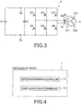
Figure 3 is a diagram showing a schematic configuration of apower converting circuit 5 of thehybrid vehicle 30. -
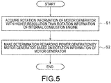
Figure 4 is a functional block diagram of the controllingapparatus 1 according to the embodiment. -
Figure 5 is a flow chart showing a controlling method according to the embodiment. -
Figure 6 is a flow chart showing an example of a determining method regarding idle power generation. -
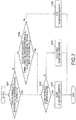
Figure 7 is a flow chart showing an example of a determining method regarding cruise power generation. - Hereinafter, an embodiment of the present invention will be described with reference to the drawings.
- First, a schematic configuration of a
hybrid vehicle 30 according to the embodiment will be described with reference toFigures 1 to 3 . - The
hybrid vehicle 30 is a hybrid-type two-wheeled vehicle (hybrid two-wheeled vehicle) including two power sources which are an internal combustion engine and an electric motor. Note that thehybrid vehicle 30 is not limited to the two-wheeled vehicle and may be another hybrid-type vehicle (such as a four-wheeled vehicle). - As shown in
Figure 1 , thehybrid vehicle 30 includes a controllingapparatus 1, an internal combustion engine (engine) 2, a motor generator (Motor Generator: MG) 3, anignition apparatus 4, apower converting circuit 5, abattery apparatus 6, astoring apparatus 7, aclutch 8, and awheel 9. Thewheel 9 ofFigure 1 represents a rear wheel of the hybrid two-wheeled vehicle. - The
controlling apparatus 1 is configured to make a determination regarding power generation by themotor generator 3. The power generation includes idle power generation and cruise power generation (power generation during running). The idle power generation is performed when theinternal combustion engine 2 is in an idle state (idling state), that is, when theinternal combustion engine 2 is rotating at a relatively low speed. On the other hand, the cruise power generation is performed when thehybrid vehicle 30 is running, that is, when theinternal combustion engine 2 is rotating at a higher speed than in the idle state. Details of thecontrolling apparatus 1 will be described later. Note that thecontrolling apparatus 1 may be provided as an ECU (Electronic Control Unit) that controls theentire hybrid vehicle 30. - The
internal combustion engine 2 uses pressure when a fuel gas (air-fuel mixture) is burned and outputs rotational driving force to thewheel 9 through theclutch 8. Acrankshaft 21 of theinternal combustion engine 2 changes up-and-down motion of pistons (not shown) into rotary motion. - Note that the type of the
internal combustion engine 2 is not particularly limited, and for example, theinternal combustion engine 2 may be a 4-stroke engine or a 2-stroke engine. Furthermore, an electronic throttle valve (not shown) may be disposed on an intake path of theinternal combustion engine 2. In this case, an accelerator position sensor reads a throttle opening set by an accelerator (grip) operation of a driver (rider) and transmits the throttle opening as an electrical signal to thecontrolling apparatus 1. Subsequently, thecontrolling apparatus 1 calculates a throttle opening based on the received set throttle opening and transmits a command to adjusting means (such as a throttle motor) of the throttle opening. - The
motor generator 3 is mechanically connected to theinternal combustion engine 2 as shown inFigure 1 . In the present embodiment, themotor generator 3 is based on an alternating current generator (ACG) and is connected to the crankshaft of theinternal combustion engine 2 all the time without a clutch. - As shown in
Figures 2 and3 , themotor generator 3 includes:stator coils internal combustion engine 2; a flywheel (magnet rotor) 32 attached to an end portion of thecrankshaft 21 of theinternal combustion engine 2; and aposition detecting unit 33 provided on theflywheel 32. Note that thestator coils Figure 2 . Furthermore, the arrangement position of theposition detecting unit 33 is not limited to the position shown inFigure 2 . - As shown in
Figure 2 , magnets of an N pole and magnets of an S pole are alternatively attached to the inside of theflywheel 32. In the present embodiment, a total of twelve magnets are attached at 30° intervals. Note that the number of magnets is not limited to twelve. Theposition detecting unit 33 transmits a pulse signal to thecontrolling apparatus 1 every time theflywheel 32 rotates 30°. Theposition detecting unit 33 is, for example, a Hall element. The Hall element is preferably provided for each phase of a U phase, a V phase, and a W phase. The pulse signal detected by the Hall element is transmitted to thecontrolling apparatus 1. - The
controlling apparatus 1 calculates a rotational speed of the motor generator 3 (flywheel 32) based on the pulse signal received from theposition detecting unit 33. A relatively large number of magnets can be provided on theflywheel 32 with a larger diameter than thecrankshaft 21. Therefore, thecontrolling apparatus 1 can use the signal of theposition detecting unit 33 to calculate the rotational speed at a higher resolution than a conventional engine rotational speed. Since theflywheel 32 is connected to thecrankshaft 21 all the time, the rotational speed of the flywheel 32 (motor generator 3) is always the same as the rotational speed of the crankshaft 21 (internal combustion engine 2). Therefore, the rotational speed of themotor generator 3 calculated by using theposition detecting unit 33 can be used as the rotational speed of theinternal combustion engine 2. - As the
flywheel 32 of themotor generator 3 rotates in synchronization with thecrankshaft 21 of theinternal combustion engine 2, alternating current power of three phases is output from thestator coils stator coils internal combustion engine 2 through theflywheel 32. - As described above, the
motor generator 3 is configured to be capable of generating power in response to the rotation of theinternal combustion engine 2 and capable of providing torque to theinternal combustion engine 2. More specifically, when themotor generator 3 is rotated and driven by theinternal combustion engine 2, themotor generator 3 generates power and outputs three-phase alternating current power to thepower converting circuit 5. Then, thepower converting circuit 5 converts the three-phase alternating current power to direct current power to charge a battery B (direct current power supply) included in thebattery apparatus 6. On the other hand, when torque is to be provided to theinternal combustion engine 2, themotor generator 3 rotates based on the three-phase alternating current power output from thepower converting circuit 5 to assist theinternal combustion engine 2. - Note that the
motor generator 3 may also function as a starting motor (self-starter) that causes theinternal combustion engine 2 to start to rotate when thehybrid vehicle 30 departs. - The
ignition apparatus 4 receives a control signal from thecontrolling apparatus 1 and ignites, at an appropriate timing, the air-fuel mixture compressed in the cylinder of theinternal combustion engine 2. Note that the kind of theignition apparatus 4 is not particularly limited, and theignition apparatus 4 may be a CDI (Capacitive Discharge Ignition) type or a full transistor type. - When the
motor generator 3 assists theinternal combustion engine 2, thepower converting circuit 5 converts the direct current power output from the battery B of thebattery apparatus 6 into alternating current power of three phases and supplies the alternating current power of three phases to themotor generator 3 to drive themotor generator 3. On the other hand, when themotor generator 3 generates power, thepower converting circuit 5 converts the three-phase alternating current power supplied from themotor generator 3 into direct current power and outputs the direct current power to the battery B of thebattery apparatus 6. - As shown in
Figure 3 , thepower converting circuit 5 includes a three-phase full-bridge circuit. Semiconductor switches Q1, Q3, and Q5 are high side switches, and semiconductor switches Q2, Q4, and Q6 are low side switches. Control terminals of the semiconductor switches Q1 to Q6 are electrically connected to thecontrolling apparatus 1. Note that the semiconductor switches Q1 to Q6 are, for example, MOSFETs, IGBTs, or the like. A smoothing capacitor C is provided between apower supply terminal 5a and apower supply terminal 5b. - The semiconductor switch Q1 is connected between the
power supply terminal 5a, to which a positive electrode of the battery B is connected, and a terminal 3a of themotor generator 3. Similarly, the semiconductor switch Q3 is connected between thepower supply terminal 5a, to which the positive electrode of the battery B is connected, and a terminal 3b of themotor generator 3. The semiconductor switch Q5 is connected between thepower supply terminal 5a, to which the positive electrode of the battery B is connected, and a terminal 3c of themotor generator 3. - The semiconductor switch Q2 is connected between the
power supply terminal 5b, to which a negative electrode of the battery B is connected, and the terminal 3a of themotor generator 3. Similarly, the semiconductor switch Q4 is connected between thepower supply terminal 5b, to which the negative electrode of the battery B is connected, and the terminal 3b of themotor generator 3. The semiconductor switch Q6 is connected between thepower supply terminal 5b, to which the negative electrode of the battery B is connected, and the terminal 3c of themotor generator 3. Note that the terminal 3a is a terminal of the U phase, the terminal 3b is a terminal of the V phase, and the terminal 3c is a terminal of the W phase. - The
battery apparatus 6 includes the chargeable and dischargeable battery B and a battery managing unit (Battery Management Unit: BMU) (not shown) that manages the battery B. The battery B can accumulate power generated by themotor generator 3 and can supply the power to themotor generator 3. The type of the battery B is not particularly limited, and for example, the battery B is a lithium ion battery. The battery managing unit transmits information (battery information) related to the voltage of the battery B and the state of the battery B to thecontrolling apparatus 1. - The storing
apparatus 7 stores information used by the controlling apparatus 1 (such as various maps and operation programs for controlling theinternal combustion engine 2 and the motor generator 3). The storingapparatus 7 is constituted by, for example, a non-volatile semiconductor memory. - Next, details of the
controlling apparatus 1 will be described with reference toFigure 4 . - The
controlling apparatus 1 includes a rotationinformation acquiring unit 11 and a powergeneration determining unit 12 as shown inFigure 4 . - The rotation
information acquiring unit 11 acquires rotation information of themotor generator 3 with a higher resolution than rotation information of theinternal combustion engine 2. Here, the "rotation information" is the rotational speed or the number of rotations. In the present embodiment, the rotationinformation acquiring unit 11 acquires the rotational speed of themotor generator 3 calculated based on the pulse signal received from theposition detecting unit 33. Note that the rotationinformation acquiring unit 11 itself may calculate the rotational speed of themotor generator 3 based on the pulse signal of theposition detecting unit 33. Since theflywheel 32 is mechanically connected to thecrankshaft 21 as described above, the rotational speed of the motor generator 3 (flywheel 32) acquired by the rotationinformation acquiring unit 11 is equal to the rotational speed of the internal combustion engine 2 (crankshaft 21). - The power
generation determining unit 12 makes a determination regarding the power generation by themotor generator 3 based on the rotation information of themotor generator 3. The powergeneration determining unit 12 sequentially makes a determination regarding the idle power generation and makes a determination regarding the cruise power generation. For example, the powergeneration determining unit 12 makes a determination regarding the idle power generation and then makes a determination regarding the cruise power generation. Since the powergeneration determining unit 12 makes the determination regarding the power generation based on the rotational speed of themotor generator 3 with a higher resolution than the rotational speed (engine rotational speed) of theinternal combustion engine 2, the powergeneration determining unit 12 can promptly make the determination regarding the power generation. - Next, details of the determination regarding the power generation by the power
generation determining unit 12 will be described. Note that an example of a determination flow will be described later with reference toFigures 6 and7 . - When starting of the
internal combustion engine 2 is completed, and a starting completion reference time has passed, the powergeneration determining unit 12 permits the idle power generation by themotor generator 3. As for the judgement of the completion of starting of theinternal combustion engine 2, the powergeneration determining unit 12 judges that the starting of theinternal combustion engine 2 is completed when the rotational speed of themotor generator 3 is equal to or greater than a prescribed threshold (internal combustion engine starting completion rotational speed). - Note that the power
generation determining unit 12 cancels the permission of the idle power generation when themotor generator 3 is in an abnormal state or when brake control is performed. This can prevent execution of the idle power generation under a situation of a malfunction of themotor generator 3 or a brake operation. The "brake control" here denotes causing the motor generator 3 (for example, motor generator based on alternating current generator ACG) to generate negative motor torque to apply the brake or putting themotor generator 3 into a short circuit state to apply the brake. The "short circuit state" denotes a state in which one of the high side switches (semiconductor switches Q1, Q3, and Q5) and the low side switches (semiconductor switches Q2, Q4, and Q6) is turned on, and the other is turned off. - When the starting of the
internal combustion engine 2 is not completed, and the rotational speed of themotor generator 3 is equal to or greater than a prescribed threshold (power generation possible reference rotational speed), the powergeneration determining unit 12 accepts the idle power generation by themotor generator 3. Note that the power generation possible reference rotational speed is a minimum rotational speed at which themotor generator 3 can generate power. The power generation possible reference rotational speed is smaller than the internal combustion engine starting completion rotational speed. When the idle power generation is accepted, once the starting of theinternal combustion engine 2 is completed, the idle power generation is permitted after the starting completion reference time has passed. - The power
generation determining unit 12 permits the cruise power generation by themotor generator 3 when the rotational speed of themotor generator 3 is equal to or greater than a high rotation reference rotational speed. Note that the powergeneration determining unit 12 cancels the permission of the cruise power generation when themotor generator 3 is in an abnormal state or when brake control is performed. This can prevent execution of the cruise power generation under a situation of a malfunction of themotor generator 3 or a brake operation. - When the cruise power generation is currently performed, the power
generation determining unit 12 continues the cruise power generation without stopping the cruise power generation even if the rotational speed of themotor generator 3 is smaller than the high rotation reference rotational speed as long as the rotational speed of themotor generator 3 is equal to or greater than a second high rotation reference rotational speed lower than the high rotation reference rotational speed. This can prevent frequent occurrence of transition between an execution state and a non-execution state of the cruise power generation. - As described, in the
controlling apparatus 1 according to the present embodiment, the rotation information of the motor generator 3 (flywheel 32) with a higher resolution than the rotation information of the internal combustion engine 2 (crankshaft 21) is acquired, and the determination regarding the power generation (idle power generation and cruise power generation) is made based on the rotation information. By using the rotation information with a high resolution, the rotational speed of theinternal combustion engine 2 can be quickly confirmed to make the determination regarding the power generation. Therefore, according to the present embodiment, the determination regarding the power generation of thehybrid vehicle 30 can be promptly made. - Next, a controlling method of the
hybrid vehicle 30 according to the present embodiment will be described with reference to flow charts ofFigures 5 to 7 . - First, the rotation
information acquiring unit 11 acquires the rotation information of the motor generator 3 (flywheel 32) with a higher resolution than the rotation information of the internal combustion engine 2 (crankshaft 21) (step S1). - After the rotation information of the
motor generator 3 is acquired, the powergeneration determining unit 12 makes a determination regarding the power generation by themotor generator 3 based on the rotation information (step S2). In the present embodiment, the determination regarding the idle power generation is made along the flow chart ofFigure 6 , and the determination regarding the cruise power generation is made along the flow chart ofFigure 7 . The flow charts ofFigures 6 and7 are sequentially executed. More specifically, the determination flow regarding the idle power generation illustrated inFigure 6 is executed, and then the determination flow regarding the cruise power generation illustrated inFigure 7 is executed. - First, the determination flow regarding the idle power generation will be described with reference to
Figure 6 . - The power
generation determining unit 12 judges whether there is a drive instruction of the motor generator 3 (step S21). If there is no drive instruction (S21; Yes), the powergeneration determining unit 12 proceeds to step S22. On the other hand, if there is a drive instruction (S21; No), the powergeneration determining unit 12 prioritizes the drive instruction and does not permit the idle power generation (step S28). - If there is no drive instruction of the
motor generator 3, the powergeneration determining unit 12 judges whether starting of theinternal combustion engine 2 is completed (step S22). Specifically, when the rotational speed indicated by the rotation information acquired in step S1 is equal to or greater than the prescribed threshold (internal combustion engine starting completion rotational speed), the powergeneration determining unit 12 judges that the starting of theinternal combustion engine 2 is completed. If the starting is completed (S22; Yes), the powergeneration determining unit 12 proceeds to step S23. On the other hand, if the starting is not completed (S22; No), the powergeneration determining unit 12 proceeds to step S25. - If the starting of the
internal combustion engine 2 is completed (S22; Yes), the powergeneration determining unit 12 judges whether the starting completion reference time has passed (step S23). If the starting completion reference time has passed (S23; Yes), the powergeneration determining unit 12 permits the idle power generation (step S24). When the idle power generation is permitted, the idle power generation is executed as long as there is no prohibition factor, such as an abnormality of themotor generator 3 and brake control. On the other hand, if the starting completion reference time has not passed (S23; No), the powergeneration determining unit 12 does not permit the idle power generation (step S28). - If the starting of the
internal combustion engine 2 is not completed (S22; No), the powergeneration determining unit 12 judges whether the rotational speed of themotor generator 3 is equal to or greater than the power generation possible reference rotational speed (step S25). If the rotational speed is equal to or greater than the power generation possible reference rotational speed (S25; Yes), the powergeneration determining unit 12 accepts the idle power generation (step S26). Once the idle power generation is accepted, the idle power generation is executed as long as there is no prohibition factor when the rotational speed becomes equal to or greater than the power generation possible reference rotational speed. - On the other hand, if the rotational speed is smaller than the power generation possible reference rotational speed (S25; No), the power
generation determining unit 12 does not permit the idle power generation (step S27). - Next, the determination flow regarding the cruise power generation will be described with reference to
Figure 7 . - The power
generation determining unit 12 determines whether the rotational speed of themotor generator 3 is equal to or greater than the high rotation reference rotational speed (step S31). If the rotational speed is equal to or greater than the high rotation reference rotational speed (S31; Yes), the powergeneration determining unit 12 proceeds to step S32. On the other hand, if the rotational speed is smaller than the high rotation reference rotational speed (S31; No), the powergeneration determining unit 12 proceeds to step S35. - If the rotational speed of the
motor generator 3 is equal to or greater than the high rotation reference rotational speed (S31; Yes), the powergeneration determining unit 12 judges whether there is a drive instruction of the motor generator 3 (step S32). If there is no drive instruction (S32; Yes), the powergeneration determining unit 12 permits the cruise power generation (step S33). On the other hand, if there is a drive instruction (S32; No), the powergeneration determining unit 12 prioritizes the drive instruction and does not permit the cruise power generation (step S34). - If the rotational speed of the
motor generator 3 is smaller than the high rotation reference rotational speed (S31; No), the powergeneration determining unit 12 judges whether the cruise power generation is currently performed and the rotational speed of themotor generator 3 is equal to or greater than the second high rotation reference rotational speed smaller than the high rotation reference rotational speed (step S35). If the rotational speed is equal to or greater than the second high rotation reference rotational speed (S35; Yes), the powergeneration determining unit 12 proceeds to step S32. On the other hand, if the rotational speed is smaller than the second high rotation reference rotational speed (S35; No), the powergeneration determining unit 12 stops the cruise power generation (step S36). - As described above, in the controlling method according to the present embodiment, the rotation information of the
motor generator 3 with a higher resolution than the rotation information (engine rotational speed) of theinternal combustion engine 2 is acquired, and the acquired rotational speed of themotor generator 3 is used in the judgement of the determination flow of the idle power generation and the determination flow of the cruise power generation. In this way, the judgement in steps S22 and S25 of the idle power generation determination flow and steps S31 and S35 of the cruise power generation determination flow can be promptly made, and as a result, the determination regarding the power generation of thehybrid vehicle 30 can be promptly made. - Although those skilled in the art may be able to conceive additional advantageous effects and various modifications of the present invention based on the description above, modes of the present invention are not limited to the individual embodiments. Constituent elements across different embodiments may be appropriately combined. Various additions, changes, and partial deletions are possible without departing from the conceptual spirit and scope of the present invention derived from the content provided in the claims and equivalents of the content.
-
- 1
- controlling apparatus
- 2
- internal combustion engine (engine)
- 21
- crankshaft
- 3
- motor generator
- 3a, 3b, 3c
- terminals
- 4
- ignition apparatus
- 5
- power converting circuit
- 5a, 5b
- power supply terminals
- 6
- battery apparatus
- 7
- storing apparatus
- 8
- clutch
- 9
- wheel
- 11
- rotation information acquiring unit
- 12
- power generation determining unit
- 30
- hybrid vehicle
- 31u, 31v, 31w
- stator coils
- 32
- flywheel
- 33
- position detecting unit
- B
- battery
- C
- smoothing capacitor
- Q1 to Q6
- semiconductor switches
Claims (11)
- A controlling apparatus of a hybrid vehicle comprising a motor generator that is mechanically connected to an internal combustion engine and that can generate power in response to rotation of the internal combustion engine and provide torque to the internal combustion engine, the controlling apparatus comprising:a rotation information acquiring unit that acquires rotation information of the motor generator with a higher resolution than rotation information of the internal combustion engine; anda power generation determining unit that makes a determination regarding the power generation by the motor generator based on the rotation information of the motor generator.
- The controlling apparatus according to claim 1, wherein
the power generation determining unit permits idle power generation by the motor generator when starting of the internal combustion engine is completed and a starting completion reference time has passed. - The controlling apparatus according to claim 2, wherein
the power generation determining unit cancels the permission of the idle power generation when the motor generator is in an abnormal state or when brake control is performed. - The controlling apparatus according to claim 1, wherein
the power generation determining unit accepts the idle power generation by the motor generator when the starting of the internal combustion engine is not completed and a rotational speed of the motor generator is equal to or greater than a power generation possible reference rotational speed. - The controlling apparatus according to claim 1, wherein
the power generation determining unit does not permit the idle power generation by the motor generator when the starting of the internal combustion engine is not completed and the rotational speed of the motor generator is smaller than a power generation possible reference rotational speed. - The controlling apparatus according to claim 1, wherein
the power generation determining unit permits cruise power generation by the motor generator when the rotational speed of the motor generator is equal to or greater than a high rotation reference rotational speed. - The controlling apparatus according to claim 6, wherein
the power generation determining unit cancels the permission of the cruise power generation when the motor generator is in an abnormal state or when brake control is performed. - The controlling apparatus according to claim 6, wherein
when the cruise power generation is currently performed, the power generation determining unit continues the cruise power generation even if the rotational speed of the motor generator is smaller than the high rotation reference rotational speed as long as the rotational speed of the motor generator is equal to or greater than a second high rotation reference rotational speed lower than the high rotation reference rotational speed. - The controlling apparatus according to claim 1, wherein
the motor generator causes the internal combustion engine to start to rotate when the hybrid vehicle departs. - The controlling apparatus according to claim 1, wherein
the hybrid vehicle is a hybrid two-wheeled vehicle. - A controlling method of a hybrid vehicle comprising a motor generator that is mechanically connected to an internal combustion engine and that can generate power in response to rotation of the internal combustion engine and provide torque to the internal combustion engine, the controlling method comprising:acquiring, by a rotation information acquiring unit, rotation information of the motor generator with a higher resolution than rotation information of the internal combustion engine; andmaking a determination, by a power generation determining unit, regarding the power generation by the motor generator based on the rotation information of the motor generator.
Applications Claiming Priority (2)
| Application Number | Priority Date | Filing Date | Title |
|---|---|---|---|
| JP2016144378 | 2016-07-22 | ||
| PCT/JP2016/076714 WO2018016086A1 (en) | 2016-07-22 | 2016-09-09 | Control apparatus and control method for hybrid vehicle |
Publications (2)
| Publication Number | Publication Date |
|---|---|
| EP3489104A1 true EP3489104A1 (en) | 2019-05-29 |
| EP3489104A4 EP3489104A4 (en) | 2019-09-18 |
Family
ID=60993081
Family Applications (1)
| Application Number | Title | Priority Date | Filing Date |
|---|---|---|---|
| EP16909561.9A Withdrawn EP3489104A4 (en) | 2016-07-22 | 2016-09-09 | CONTROL APPARATUS AND CONTROL METHOD FOR A HYBRID VEHICLE |
Country Status (4)
| Country | Link |
|---|---|
| US (1) | US10906523B2 (en) |
| EP (1) | EP3489104A4 (en) |
| JP (1) | JP6383970B2 (en) |
| WO (1) | WO2018016086A1 (en) |
Family Cites Families (16)
| Publication number | Priority date | Publication date | Assignee | Title |
|---|---|---|---|---|
| JP3099698B2 (en) * | 1995-05-19 | 2000-10-16 | トヨタ自動車株式会社 | Power transmission device and control method thereof |
| US5789823A (en) * | 1996-11-20 | 1998-08-04 | General Motors Corporation | Electric hybrid transmission with a torque converter |
| JP4045657B2 (en) * | 1998-08-04 | 2008-02-13 | 株式会社デンソー | Vehicle power generation device |
| JP2000103384A (en) * | 1998-09-30 | 2000-04-11 | Honda Motor Co Ltd | Vehicle with hybrid power unit |
| JP2000205002A (en) * | 1999-01-06 | 2000-07-25 | Hitachi Ltd | Control device and control method for hybrid vehicle drive device |
| JP2001107765A (en) * | 1999-10-08 | 2001-04-17 | Honda Motor Co Ltd | Hybrid vehicle control device |
| JP3775562B2 (en) * | 2000-03-07 | 2006-05-17 | ジヤトコ株式会社 | Parallel hybrid vehicle |
| JP2004274842A (en) | 2003-03-06 | 2004-09-30 | Suzuki Motor Corp | Alternator power generation control device |
| JP4094492B2 (en) * | 2003-06-13 | 2008-06-04 | 本田技研工業株式会社 | Hybrid vehicle |
| JP4460331B2 (en) * | 2004-03-08 | 2010-05-12 | ヤマハ発動機株式会社 | Motorcycle |
| US7213657B2 (en) * | 2004-03-29 | 2007-05-08 | Weatherford/Lamb, Inc. | Apparatus and methods for installing instrumentation line in a wellbore |
| DE102006012384A1 (en) | 2006-03-15 | 2007-09-20 | Iav Gmbh Ingenieurgesellschaft Auto Und Verkehr | Hybrid vehicle starting method, involves starting internal combustion engine in mode of operation from idleness without mechanical drive of internal combustion engine, where fuel ignition takes place after fuel injection into cylinder |
| JP4527138B2 (en) * | 2007-07-12 | 2010-08-18 | 本田技研工業株式会社 | Control device for hybrid vehicle |
| JP5146502B2 (en) * | 2009-11-12 | 2013-02-20 | トヨタ自動車株式会社 | Secondary battery charge / discharge controller |
| EP2657099B1 (en) * | 2010-12-22 | 2018-04-25 | Toyota Jidosha Kabushiki Kaisha | Vehicle and vehicle control method |
| JP6047930B2 (en) * | 2012-06-04 | 2016-12-21 | 日産自動車株式会社 | Vehicle power supply |
-
2016
- 2016-09-09 WO PCT/JP2016/076714 patent/WO2018016086A1/en not_active Ceased
- 2016-09-09 JP JP2017556999A patent/JP6383970B2/en active Active
- 2016-09-09 EP EP16909561.9A patent/EP3489104A4/en not_active Withdrawn
- 2016-09-09 US US16/093,788 patent/US10906523B2/en not_active Expired - Fee Related
Also Published As
| Publication number | Publication date |
|---|---|
| US10906523B2 (en) | 2021-02-02 |
| US20200180593A1 (en) | 2020-06-11 |
| JP6383970B2 (en) | 2018-09-05 |
| JPWO2018016086A1 (en) | 2018-07-19 |
| WO2018016086A1 (en) | 2018-01-25 |
| EP3489104A4 (en) | 2019-09-18 |
Similar Documents
| Publication | Publication Date | Title |
|---|---|---|
| EP3617467B1 (en) | Vehicle and control method for vehicle | |
| EP3489103B1 (en) | Control apparatus and control method for hybrid vehicle | |
| WO2014073632A1 (en) | Power source device | |
| JPS61155625A (en) | Torque fluctuation restraining device of engine | |
| US10066591B2 (en) | Process for starting an internal combustion engine | |
| US20080179889A1 (en) | Vehicle battery charger and method of operating same | |
| US10906523B2 (en) | Control apparatus and control method for hybrid vehicle | |
| JP7488994B2 (en) | Hybrid Vehicles | |
| TWI764426B (en) | straddle vehicle | |
| JP2006121784A (en) | Control device for hybrid vehicle | |
| JP6851734B2 (en) | Charge amount calculation device | |
| JPH05302525A (en) | Device for restraining variation in engine speed | |
| JP6379306B2 (en) | Control device and control method for hybrid vehicle | |
| EP3376018A2 (en) | System and method for positioning a crankshaft of an engine of a vehicle | |
| JP6948845B2 (en) | Electronic control device | |
| JP4421503B2 (en) | Engine ignition control device | |
| JP6234737B2 (en) | Vehicle control device | |
| JP5637742B2 (en) | Method for controlling generator of internal combustion engine | |
| JP6095428B2 (en) | Control device | |
| JP2021080842A (en) | Engine start control device | |
| JP2023157535A (en) | Vehicle control device | |
| JP2016205200A (en) | Control device | |
| KR20100021214A (en) | Integrated motor control apparetus for vehicle starter-alternator | |
| JPH01240750A (en) | Control device for engine | |
| JPH01182539A (en) | Torque fluctuation control device for engine |
Legal Events
| Date | Code | Title | Description |
|---|---|---|---|
| STAA | Information on the status of an ep patent application or granted ep patent |
Free format text: STATUS: THE INTERNATIONAL PUBLICATION HAS BEEN MADE |
|
| PUAI | Public reference made under article 153(3) epc to a published international application that has entered the european phase |
Free format text: ORIGINAL CODE: 0009012 |
|
| STAA | Information on the status of an ep patent application or granted ep patent |
Free format text: STATUS: REQUEST FOR EXAMINATION WAS MADE |
|
| 17P | Request for examination filed |
Effective date: 20180912 |
|
| AK | Designated contracting states |
Kind code of ref document: A1 Designated state(s): AL AT BE BG CH CY CZ DE DK EE ES FI FR GB GR HR HU IE IS IT LI LT LU LV MC MK MT NL NO PL PT RO RS SE SI SK SM TR |
|
| AX | Request for extension of the european patent |
Extension state: BA ME |
|
| A4 | Supplementary search report drawn up and despatched |
Effective date: 20190816 |
|
| RIC1 | Information provided on ipc code assigned before grant |
Ipc: B60L 50/16 20190101ALI20190809BHEP Ipc: B60W 10/08 20060101AFI20190809BHEP Ipc: B60W 20/00 20160101ALI20190809BHEP Ipc: B60K 6/485 20071001ALI20190809BHEP |
|
| DAV | Request for validation of the european patent (deleted) | ||
| DAX | Request for extension of the european patent (deleted) | ||
| STAA | Information on the status of an ep patent application or granted ep patent |
Free format text: STATUS: EXAMINATION IS IN PROGRESS |
|
| 17Q | First examination report despatched |
Effective date: 20200602 |
|
| STAA | Information on the status of an ep patent application or granted ep patent |
Free format text: STATUS: THE APPLICATION IS DEEMED TO BE WITHDRAWN |
|
| RAP3 | Party data changed (applicant data changed or rights of an application transferred) |
Owner name: SHINDENGEN ELECTRIC MANUFACTURING CO., LTD. Owner name: HONDA MOTOR CO., LTD. |
|
| 18D | Application deemed to be withdrawn |
Effective date: 20250401 |