EP3376018A2 - System and method for positioning a crankshaft of an engine of a vehicle - Google Patents
System and method for positioning a crankshaft of an engine of a vehicle Download PDFInfo
- Publication number
- EP3376018A2 EP3376018A2 EP18154097.2A EP18154097A EP3376018A2 EP 3376018 A2 EP3376018 A2 EP 3376018A2 EP 18154097 A EP18154097 A EP 18154097A EP 3376018 A2 EP3376018 A2 EP 3376018A2
- Authority
- EP
- European Patent Office
- Prior art keywords
- engine
- crankshaft
- key
- processor
- main switch
- Prior art date
- Legal status (The legal status is an assumption and is not a legal conclusion. Google has not performed a legal analysis and makes no representation as to the accuracy of the status listed.)
- Granted
Links
- 238000000034 method Methods 0.000 title claims abstract description 46
- 239000007858 starting material Substances 0.000 claims abstract description 47
- 230000006835 compression Effects 0.000 claims abstract description 19
- 238000007906 compression Methods 0.000 claims abstract description 19
- 238000010248 power generation Methods 0.000 claims description 18
- 238000002485 combustion reaction Methods 0.000 claims description 11
- 238000013459 approach Methods 0.000 claims description 5
- 239000000446 fuel Substances 0.000 description 7
- 238000010586 diagram Methods 0.000 description 4
- 239000000203 mixture Substances 0.000 description 4
- 230000001105 regulatory effect Effects 0.000 description 3
- 238000005259 measurement Methods 0.000 description 2
- 230000005856 abnormality Effects 0.000 description 1
- 230000002411 adverse Effects 0.000 description 1
- 230000033228 biological regulation Effects 0.000 description 1
- 238000004891 communication Methods 0.000 description 1
- 230000001276 controlling effect Effects 0.000 description 1
- 230000008878 coupling Effects 0.000 description 1
- 238000010168 coupling process Methods 0.000 description 1
- 238000005859 coupling reaction Methods 0.000 description 1
- 230000005674 electromagnetic induction Effects 0.000 description 1
- 230000007774 longterm Effects 0.000 description 1
- 238000004064 recycling Methods 0.000 description 1
Images


Classifications
-
- F—MECHANICAL ENGINEERING; LIGHTING; HEATING; WEAPONS; BLASTING
- F02—COMBUSTION ENGINES; HOT-GAS OR COMBUSTION-PRODUCT ENGINE PLANTS
- F02N—STARTING OF COMBUSTION ENGINES; STARTING AIDS FOR SUCH ENGINES, NOT OTHERWISE PROVIDED FOR
- F02N19/00—Starting aids for combustion engines, not otherwise provided for
- F02N19/005—Aiding engine start by starting from a predetermined position, e.g. pre-positioning or reverse rotation
-
- F—MECHANICAL ENGINEERING; LIGHTING; HEATING; WEAPONS; BLASTING
- F02—COMBUSTION ENGINES; HOT-GAS OR COMBUSTION-PRODUCT ENGINE PLANTS
- F02N—STARTING OF COMBUSTION ENGINES; STARTING AIDS FOR SUCH ENGINES, NOT OTHERWISE PROVIDED FOR
- F02N11/00—Starting of engines by means of electric motors
- F02N11/08—Circuits or control means specially adapted for starting of engines
- F02N11/0862—Circuits or control means specially adapted for starting of engines characterised by the electrical power supply means, e.g. battery
-
- F—MECHANICAL ENGINEERING; LIGHTING; HEATING; WEAPONS; BLASTING
- F02—COMBUSTION ENGINES; HOT-GAS OR COMBUSTION-PRODUCT ENGINE PLANTS
- F02D—CONTROLLING COMBUSTION ENGINES
- F02D2200/00—Input parameters for engine control
- F02D2200/02—Input parameters for engine control the parameters being related to the engine
- F02D2200/04—Engine intake system parameters
- F02D2200/0406—Intake manifold pressure
-
- F—MECHANICAL ENGINEERING; LIGHTING; HEATING; WEAPONS; BLASTING
- F02—COMBUSTION ENGINES; HOT-GAS OR COMBUSTION-PRODUCT ENGINE PLANTS
- F02N—STARTING OF COMBUSTION ENGINES; STARTING AIDS FOR SUCH ENGINES, NOT OTHERWISE PROVIDED FOR
- F02N11/00—Starting of engines by means of electric motors
- F02N11/04—Starting of engines by means of electric motors the motors being associated with current generators
-
- F—MECHANICAL ENGINEERING; LIGHTING; HEATING; WEAPONS; BLASTING
- F02—COMBUSTION ENGINES; HOT-GAS OR COMBUSTION-PRODUCT ENGINE PLANTS
- F02N—STARTING OF COMBUSTION ENGINES; STARTING AIDS FOR SUCH ENGINES, NOT OTHERWISE PROVIDED FOR
- F02N11/00—Starting of engines by means of electric motors
- F02N11/08—Circuits or control means specially adapted for starting of engines
- F02N11/0814—Circuits or control means specially adapted for starting of engines comprising means for controlling automatic idle-start-stop
-
- F—MECHANICAL ENGINEERING; LIGHTING; HEATING; WEAPONS; BLASTING
- F02—COMBUSTION ENGINES; HOT-GAS OR COMBUSTION-PRODUCT ENGINE PLANTS
- F02N—STARTING OF COMBUSTION ENGINES; STARTING AIDS FOR SUCH ENGINES, NOT OTHERWISE PROVIDED FOR
- F02N11/00—Starting of engines by means of electric motors
- F02N11/08—Circuits or control means specially adapted for starting of engines
- F02N11/0862—Circuits or control means specially adapted for starting of engines characterised by the electrical power supply means, e.g. battery
- F02N11/0866—Circuits or control means specially adapted for starting of engines characterised by the electrical power supply means, e.g. battery comprising several power sources, e.g. battery and capacitor or two batteries
-
- F—MECHANICAL ENGINEERING; LIGHTING; HEATING; WEAPONS; BLASTING
- F02—COMBUSTION ENGINES; HOT-GAS OR COMBUSTION-PRODUCT ENGINE PLANTS
- F02N—STARTING OF COMBUSTION ENGINES; STARTING AIDS FOR SUCH ENGINES, NOT OTHERWISE PROVIDED FOR
- F02N11/00—Starting of engines by means of electric motors
- F02N11/08—Circuits or control means specially adapted for starting of engines
- F02N11/087—Details of the switching means in starting circuits, e.g. relays or electronic switches
-
- F—MECHANICAL ENGINEERING; LIGHTING; HEATING; WEAPONS; BLASTING
- F02—COMBUSTION ENGINES; HOT-GAS OR COMBUSTION-PRODUCT ENGINE PLANTS
- F02N—STARTING OF COMBUSTION ENGINES; STARTING AIDS FOR SUCH ENGINES, NOT OTHERWISE PROVIDED FOR
- F02N2200/00—Parameters used for control of starting apparatus
- F02N2200/02—Parameters used for control of starting apparatus said parameters being related to the engine
- F02N2200/022—Engine speed
Definitions
- the disclosure relates to positioning a crankshaft of an engine of a vehicle, and more particularly to a system and a method for positioning a crankshaft of an engine of a vehicle when a main switch of the vehicle is switched from a Key ON state to a Key OFF state.
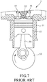
- FIG. 7 illustrates a four-stroke engine 5.
- the four-stroke engine 5 includes a cylinder 51, a piston 52, a crankshaft 53, a coupling rod 54 interconnecting the piston 52 and the crankshaft 53, an igniter 55, an intake valve 56 and an exhaust valve 57.
- the piston 52 is brought to reciprocate in the cylinder 51 by rotation of the crankshaft 53.
- the intake valve 56 controls flow of an air-fuel mixture (or atomized fuel) into the cylinder 51 via an inlet where the air-fuel mixture is to be compressed by the piston 52 and ignited by the igniter 55.
- the exhaust valve controls flow of the air-fuel mixture, which underwent the compression and ignition, out of the cylinder 51 via an outlet.
- a complete cycle of the four-stroke engine 5 includes the aforesaid four strokes during which the crankshaft 53 completes two full 360-degree revolutions.
- crankshaft 53 of the four-stroke engine 5 stops at an angular position corresponding to the compression stroke, compared with a scenario where the crankshaft 53 stops at an angular position not corresponding to the compression stroke (i.e., one of the strokes other than the compression stroke, such as the intake stroke, the combustion stroke or the exhaust stroke), more torque is required to be applied by a starter motor on the crankshaft 53 for restarting the four-stroke engine 5. As a result, more electric power is consumed, and performance of the starter motor may be adversely affected in the long term.
- FIG 1 illustrates a conventional control system, which is utilized to implement a conventional control method disclosed in Taiwanese Invention Patent No. 1476320 for positioning a crankshaft of an engine of a vehicle when the engine of the vehicle is shut down by a start-stop function of the vehicle so as to reduce torque required to restart the engine the next time.
- the start-stop function allows an internal combustion engine of the vehicle to automatically shut down and restart, so as to reduce the amount of time the engine spends idling.
- the control system includes a Manifold Absolute Pressure (MAP) sensor 11, a crankshaft position sensor 12, an Integrated Starter Generator (ISG) controller 13, an integrated starter generator 14 and a battery 15.
- the integrated starter generator 14 is electrically connected to the ISG controller 13 and the battery 15.
- the MAP sensor 11 measures cylinder pressure of the engine so as to obtain a measured pressure value representative of a result of measurement of the cylinder pressure.
- the crankshaft position sensor 12 measures the angular position of the crankshaft so as to obtain a detected angular value representative of a result of measurement of the angular position of the crankshaft.
- the ISG controller 13 receives the measured pressure value from the MAP sensor 11 and the detected angular value from the crankshaft position sensor 12.
- the ISG controller 13 controls the integrated starter generator 14 to position the crankshaft at the angular position corresponding to the non-compression stroke based on the measured pressure value and the detected angular value when the engine is shut down by the start-stop function.
- the crankshaft cannot be controlled to stop at an appropriate angular position for an easier start of the engine next time, where lower torque is required for actuating revolution of the crankshaft to start up the engine.
- an object of the disclosure is to provide a system and a method for positioning a crankshaft of an engine of a vehicle that can alleviate at least one of the drawbacks of the prior art.
- the system includes a main switch and an Integrated Starter Generator, ISG, controller.
- the ISG controller is electrically connected to the main switch.
- the ISG controller is configured to continuously receive a signal indicating an engine speed at which the engine is currently operating.
- the ISG controller is configured to determine, after the main switch is switched from a Key ON state to a Key OFF state where the ISG controller is powered by an auxiliary power source, whether the engine speed is lower than a predetermined threshold for positioning the crankshaft.
- the ISG controller is configured to perform, when it is determined that the engine speed is lower than the predetermined threshold for positioning the crankshaft, a crankshaft positioning process so that an angular position of the crankshaft does not correspond to a compression stroke of the engine while the crankshaft stops.
- the method is to be implemented by the system mentioned above .
- the method includes steps of:
- the engine may be one of a single-cylinder engine and a multiple-cylinder engine.
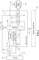
- the system includes a main switch 20, an Integrated Starter Generator (ISG) controller 21, an integrated starter generator 24, a rotor position sensor 25, and a power relay 26.
- ISG Integrated Starter Generator
- the main switch 20 is electrically connected to a battery 22 and the power relay 26.
- the ISG controller 21 is electrically connected to the main switch 20, an Engine Control Unit (ECU) 23, and the integrated starter generator 24. Specifically speaking, the ISG controller 21 is electrically connected through a communication interface 27 to the ECU 23.
- the integrated starter generator 24 is to be coupled to the engine.
- the battery 22 is configured to supply electrical power to the ISG controller 21 and the ECU 23.
- the main switch 20 is configured to be switched between a Key OFF state, and a Key ON state where the ISG controller 21 is powered by the battery 22.
- the main switch 20 can be operated to switch to the Key OFF state so as to stop the engine and cut off electrical power supply from the battery 22 to electrical components of the vehicle while the ISG controller 21 is still powered by an auxiliary power source.
- the ECU 23 is configured to control electronic parts or actuators operatively associated with the engine of the vehicle, such as a fuel injector, an ignition coil, and so on, so as to start or stop the engine.
- the integrated starter generator 24 is a brushless electric motor coupled to the crankshaft of the engine.
- the integrated starter generator 24 is configured to provide forward torque or reverse torque on the crankshaft so as to start the engine, generate electrical power, or position the crankshaft.
- the ISG controller 21 determines that an abnormality occurs in the system, the ISG controller 21 is configured to control the power relay 26 to cut off an electrical path between the integrated starter generator 24 and the battery 22 so as to protect related electronic components of the system from being burned out.
- the power relay 26 is optional, and in other embodiment, the power relay 26 may be omitted.
- the ISG controller 21 is configured to continuously receive, from the rotor position sensor 25, a signal indicating an angular position that a rotor (not shown) of the integrated starter generator 24 is currently at, so that the ISG controller 21 can accurately control three-phase power supply for electromagnetic induction in the integrated starter generator 24.
- the ISG controller 21 further continuously receives a signal indicating an engine speed at which the engine is currently operating, and a signal indicating the angular position that the crankshaft is currently at. These signals may serve as references for the ISG controller 21 to perform a post engine shutdown control process, which is a control process to be performed after the engine has been turned off.
- the ISG controller 21 is configured to receive from the ECU 23, after the main switch 20 is switched from the Key OFF state to the Key ON state, a start command for starting up the engine.
- the ISG controller 21 is configured to refrain from receiving from the ECU 23, after the main switch 20 is switched from the Key ON state to the Key OFF state, the start command for starting up the engine. Meanwhile, the ECU 23 turns off the electronic parts or actuators operatively associated with the engine for stopping the engine.
- the ISG controller 21 is configured to determine, after the main switch 20 is switched from the Key ON state to the Key OFF state, whether the engine speed is lower than a predetermined threshold below which positioning of the crankshaft can be conducted (also called “predetermined threshold for positioning the crankshaft” herein).
- the predetermined threshold for positioning the crankshaft is decided by taking into account the inertia of the crankshaft during stoppage of the engine so that the crankshaft can be appropriately positioned.
- the predetermined threshold for positioning the crankshaft may be implemented as 800 RPM, but is not limited thereto.
- the ISG controller 21 is configured to perform, when it is determined that the engine speed is lower than the predetermined threshold for positioning the crankshaft, a crankshaft positioning process so that an angular position of the crankshaft does not correspond to a compression stroke of the engine when the crankshaft stops.
- the crankshaft may be positioned at an angular position corresponding to a combustion stroke for an easier start of the engine next time.
- the ISG controller 21 includes a main switch detector 211, an electronic switch 212, a self-sustaining power circuit 213, a processor 214, a power transistor 215 and a gate driver 216.
- the electronic switch 212 is to be electrically connected to the battery 22.
- the processor 214 is electrically connected to the main switch detector 211, the electronic switch 212 and the self-sustaining power circuit 213.
- the power transistor 215 is electrically connected between the processor 214 and the integrated starter generator 24, and is configured to form the electrical path, which extends from the battery 22, through the power relay 26 and the power transistor 215 to the integrated starter generator 24.
- the processor 214 is implemented by a microcontroller.
- the main switch detector 211 When the main switch 20 is switched from the Key OFF state to the Key ON state, the main switch detector 211 is configured to generate a Key ON indication signal indicating that the main switch 20 is in the Key ON state, and to transmit the Key ON indication signal to the processor 214.
- the processor 214 Powered by the battery 20, the processor 214 is configured to receive the Key ON indication signal .
- the processor 214 is configured to enable, in response to receipt of the Key ON indication signal, the electronic switch 212 to conduct for allowing passage of an electrical flow from the battery 22 through the electronic switch 212 and the self-sustaining power circuit 213 to the processor 214 so that the battery 22 serves as the auxiliary power source when the main switch is switched to the Key OFF state.
- the self-sustaining power circuit 213 is implemented by a conducting circuit for allowing passage of the electrical flow, so that when the main switch is switched to the Key NO state, the electrical flow which originates from the battery 22 can go through the main switch 20 and the self-sustaining power circuit 213 to the processor 214 or go through the electronic switch 212 and the self-sustaining power circuit 213 to the processor 214.
- the main switch 20 is switched to the Key OFF state, the electrical flow which originates from the battery 22 can still go through the electronic switch 212 and the self-sustaining power circuit 213 to the processor 214 for allowing the ISG controller 21 to be powered by the auxiliary power source (i.e., the batter 22).
- the processor 214 is configured to receive the start command from the ECU 23 for starting up the engine. Actuated by the ECU 23 with the start command, the ISG controller 21 controls the integrated starter generator 24 to provide forward torque on the crankshaft so as to start the engine.
- the main switch detector 211 When the main switch 20 is switched from the Key ON state to the Key OFF state, the main switch detector 211 is configured to generate a Key OFF indication signal indicating that the main switch 20 is in the Key OFF state, and to transmit the Key OFF indication signal to the processor 214.
- the processor 214 Powered by the auxiliary power source, the processor 214 is configured to determine whether the engine speed is lower than a predetermined threshold above which power generation can be conducted (also called “predetermined threshold for power generation" herein).
- the predetermined threshold for power generation is implemented as 1000 RPM, but is not limited thereto.
- the processor 214 is configured to control, when it is determined that the engine speed is not lower than the predetermined threshold for power generation, the integrated starter generator 24 to generate electrical power by rotation of the crankshaft of the engine, to regulate the electrical power thus generated, and to provide the electrical power thus regulated to the battery 22 for charging the same.
- the processor 214 is configured to turn off, when it is determined that the engine speed is lower than the predetermined threshold for power generation, the power transistor 215 to cease the power generation by the integrated starter generator 24.
- the processor 214 is configured to determine whether the angular position of the crankshaft is equal to a preset angular position.
- the preset angular position is set to ensure that the crankshaft will be positioned at an angular position following the preset angular position in a rotational direction of the crankshaft.
- the preset angular position is implemented to correspond to the top dead center of a piston in the engine, which ends the compression stroke, i.e., initiates the combustion stroke, so as to prevent the crankshaft from being stopped at an angular position corresponding to the compression stroke.
- the processor 214 is configured to control, when it is determined that the angular position of the crankshaft is equal to the preset angular position, the integrated starter generator 24 to output reverse torque to the crankshaft of the engine.
- the processor 214 is configured to stop the integrated starter generator 24 from outputting the reverse torque when it is determined that the engine speed approaches zero and the angular position of the crankshaft corresponds to the combustion stroke of the engine.
- FIG. 2 to 6 an embodiment of a method for positioning a crankshaft of an engine of a vehicle according to this disclosure is illustrated.
- the method is to be implemented by the system that is previously described.
- the method includes the following steps.
- the main switch detector 211 when the main switch 20 is switched from the Key OFF state to the Key ON state in step S31, the main switch detector 211 generates the Key ON indication signal and transmits the Key ON indication signal to the processor 214.
- step S32 the processor 214 enables, in response to receipt of the Key ON indication signal, the electronic switch 212 to conduct for allowing passage of the electrical flow from the battery 22 through the electronic switch 212 and the self-sustaining power circuit 213 to the processor 214 so that the battery 22 serves as the auxiliary power source when the main switch 20 is switched to the Key OFF state as shown in step S33.
- step S34 the ISG controller 21 controls the power relay 26 to conduct for establishing the electrical path between the integrated starter generator 24 and the battery 22.
- step S35 the processor 214 receives the start command from the ECU 23, if the ECU 23 sends any to the ISG controller 21, for starting up the engine.
- the main switch detector 211 when the main switch 20 is switched from the Key ON state to the Key OFF state in step S40, the main switch detector 211 generates the Key OFF indication signal and transmits the Key OFF indication signal to the processor 214.
- step S41 when the main switch 20 is in the Key OFF state, an intake valve of the engine is controlled by the ECU 23 to close for preventing an air-fuel mixture (or atomized fuel) from flowing into a cylinder of the engine, and an igniter of the engine is deactivated by the ECU 23, so that the engine is turned off.
- an intake valve of the engine is controlled by the ECU 23 to close for preventing an air-fuel mixture (or atomized fuel) from flowing into a cylinder of the engine, and an igniter of the engine is deactivated by the ECU 23, so that the engine is turned off.
- step S42 the ISG controller 21 refrains from receiving, after the main switch 20 is switched from the Key ON state to the Key OFF state where the engine is turned off, the start command for starting up the engine from the ECU 23.
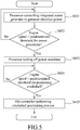
- step S43 powered by the auxiliary power source, the ISG controller 21 performs the post engine shutdown control process which includes sub-steps S431 to S435 described below and illustrated in Figure 5 .
- sub-step S431 the processor 214 of the ISG controller 21 controls the integrated starter generator 24 to generate electrical power by rotation of the crankshaft of the engine and to regulate the electrical power thus generated.
- the processor 214 determines whether the engine speed is lower than the predetermined threshold for power generation. When it is determined that the engine speed is not lower than the predetermined threshold for power generation, the processor 214 keeps controlling the integrated starter generator 24 to generate electrical power by rotation of the crankshaft of the engine, and to regulate the electrical power thus generated as shown in sub-step S431. The electrical power thus generated and regulated can be utilized to charge the battery 22, so energy recycling is realized while the engine of the vehicle is turned off.
- sub-step S433 when it is determined that the engine speed is lower than the predetermined threshold for power generation, the processor 214 turns off the power transistor 215 to cease the power generation and the power regulation by the integrated starter generator 24.
- sub-step S434 the ISG controller 21 determines, after the main switch 20 is switched from the Key ON state to the Key OFF state in sub-step S40, whether the engine speed is lower than the predetermined threshold for positioning the crankshaft. When it is determined that the engine speed is not lower than the predetermined threshold for positioning the crankshaft, sub-step S434 is repeated. On the other hand, when it is determined that the engine speed is lower than the predetermined threshold for positioning the crankshaft, the ISG controller 21 performs the crankshaft positioning process as shown in sub-step S435 so that an angular position of the crankshaft does not correspond to the compression stroke of the engine when the crankshaft stops revolving.
- crankshaft positioning process in sub-step S435 includes sub-steps S4351 to S4354 described below.
- sub-step S4351 the processor 214 determines whether the angular position of the crankshaft is equal to the preset angular position. When it is determined that the angular position of the crankshaft is not equal to the preset angular position, the processor 214 performs sub-step S4351 once again.
- the flow proceeds to sub-step S4352, in which the processor 214 controls the integrated starter generator 24 to output reverse torque to the crankshaft of the engine.
- the reverse torque is associated with a Pulse Width Modulation (PWM) signal outputted by the ISG controller 21 to the integrated starter generator 24, and magnitude of the reverse torque is positively related to a duty cycle of the PWM signal. That is to say, to stop the engine, the higher the speed of the engine, the greater the magnitude of the required reverse torque, and consequently the greater the duty cycle of the PWM signal.
- PWM Pulse Width Modulation
- sub-step S4353 the processor 214 determines whether the engine speed approaches zero and the angular position of the crankshaft corresponds to the non-compression stroke (e.g., the combustion stroke) of the engine. When a result of the determination is negative, e.g., the engine speed is much greater than zero or the angular position of the crankshaft corresponds to the compression stroke, sub-steps 4352 and 4353 are repeated so as to continue on positioning the crankshaft.
- the non-compression stroke e.g., the combustion stroke
- sub-step S4353 when it is determined in sub-step S4353 that the engine speed approaches zero and the angular position of the crankshaft corresponds to the non-compression stroke (i.e., the combustion stroke) of the engine, the flow proceeds to sub-step S4354, where the processor 214 stops the integrated starter generator 24 from outputting the reverse torque. Consequently, the crankshaft positioning process in sub-step S435 is completed and so is the post engine shutdown control process in step S43.
- step S44 in Figure 4 the processor 214 turns off the power relay 26.
- step S45 the processor 214 turns off the electronic switch 212 to cut off the electrical flow from the battery 22 through the electronic switch 212 and the self-sustaining power circuit 213 to the processor 214, so the system is entirely turned off in step S46.
- the method of this disclosure utilizes the auxiliary power source, which is established by means of the battery 22, the electronic switch 212 and the self-sustaining power circuit 213, to power the system so that power supply to the ISG controller 21 is not cut off immediately, allowing the ISG controller 21 to perform the crankshaft positioning process for positioning the crankshaft at an angular position corresponding to the non-compression stroke of the engine when the crankshaft stops. Therefore, the next start of the engine can be smoother and requires less energy to overcome the resistance in the engine.
- the electrical power generated and regulated while the engine is turned off but the crankshaft in the engine is still revolving can be recycled to the battery 22, so energy is utilized more efficiently.
Abstract
Description
- The disclosure relates to positioning a crankshaft of an engine of a vehicle, and more particularly to a system and a method for positioning a crankshaft of an engine of a vehicle when a main switch of the vehicle is switched from a Key ON state to a Key OFF state.
-
Figure 7 illustrates a four-stroke engine 5. The four-stroke engine 5 includes acylinder 51, apiston 52, acrankshaft 53, acoupling rod 54 interconnecting thepiston 52 and thecrankshaft 53, anigniter 55, anintake valve 56 and anexhaust valve 57. Thepiston 52 is brought to reciprocate in thecylinder 51 by rotation of thecrankshaft 53. Theintake valve 56 controls flow of an air-fuel mixture (or atomized fuel) into thecylinder 51 via an inlet where the air-fuel mixture is to be compressed by thepiston 52 and ignited by theigniter 55. The exhaust valve controls flow of the air-fuel mixture, which underwent the compression and ignition, out of thecylinder 51 via an outlet. During movement of thepiston 52 in thecylinder 51, four separate strokes take place in the four-stroke engine 5, namely, an intake stroke, a compression stroke, a combustion stroke and an exhaust stroke. The four strokes of the four-stroke engine 5 correspond respectively to different angular positions, namely, 0-180 degrees, 180-360 degrees, 360-540 degrees and 540-720 degrees, of thecrankshaft 53 of the four-stroke engine 5 as shown inFigure 8 . It should be noted that a complete cycle of the four-stroke engine 5 includes the aforesaid four strokes during which thecrankshaft 53 completes two full 360-degree revolutions. - When the
crankshaft 53 of the four-stroke engine 5 stops at an angular position corresponding to the compression stroke, compared with a scenario where thecrankshaft 53 stops at an angular position not corresponding to the compression stroke (i.e., one of the strokes other than the compression stroke, such as the intake stroke, the combustion stroke or the exhaust stroke), more torque is required to be applied by a starter motor on thecrankshaft 53 for restarting the four-stroke engine 5. As a result, more electric power is consumed, and performance of the starter motor may be adversely affected in the long term. -
Figure 1 illustrates a conventional control system, which is utilized to implement a conventional control method disclosed in Taiwanese Invention Patent No.1476320 crankshaft position sensor 12, an Integrated Starter Generator (ISG)controller 13, an integratedstarter generator 14 and abattery 15. The integratedstarter generator 14 is electrically connected to theISG controller 13 and thebattery 15. The MAP sensor 11 measures cylinder pressure of the engine so as to obtain a measured pressure value representative of a result of measurement of the cylinder pressure. Thecrankshaft position sensor 12 measures the angular position of the crankshaft so as to obtain a detected angular value representative of a result of measurement of the angular position of the crankshaft. TheISG controller 13 receives the measured pressure value from the MAP sensor 11 and the detected angular value from thecrankshaft position sensor 12. Powered by thebattery 15 when a main switch of the vehicle is in a Key ON state, theISG controller 13 controls the integratedstarter generator 14 to position the crankshaft at the angular position corresponding to the non-compression stroke based on the measured pressure value and the detected angular value when the engine is shut down by the start-stop function. However, when the vehicle is stopped and the main switch is switched to a Key OFF state for turning off the engine, since theISG controller 13 is no longer powered by thebattery 15, the crankshaft cannot be controlled to stop at an appropriate angular position for an easier start of the engine next time, where lower torque is required for actuating revolution of the crankshaft to start up the engine. - Therefore, an object of the disclosure is to provide a system and a method for positioning a crankshaft of an engine of a vehicle that can alleviate at least one of the drawbacks of the prior art.
- According to one aspect of the disclosure, the system includes a main switch and an Integrated Starter Generator, ISG, controller. The ISG controller is electrically connected to the main switch. The ISG controller is configured to continuously receive a signal indicating an engine speed at which the engine is currently operating. The ISG controller is configured to determine, after the main switch is switched from a Key ON state to a Key OFF state where the ISG controller is powered by an auxiliary power source, whether the engine speed is lower than a predetermined threshold for positioning the crankshaft. The ISG controller is configured to perform, when it is determined that the engine speed is lower than the predetermined threshold for positioning the crankshaft, a crankshaft positioning process so that an angular position of the crankshaft does not correspond to a compression stroke of the engine while the crankshaft stops.
- According to another aspect of the disclosure, the method is to be implemented by the system mentioned above . The method includes steps of:
- a) determining, by the ISG controller after the main switch is switched from a Key ON state to a Key OFF state where the ISG controller is powered by an auxiliary power source, whether the engine speed is lower than a predetermined threshold for positioning the crankshaft; and
- b) performing, by the ISG controller when it is determined that the engine speed is lower than the predetermined threshold for positioning the crankshaft, a crankshaft positioning process so that an angular position of the crankshaft does not correspond to a compression stroke of the engine while the crankshaft stops.
- Other features and advantages of the disclosure will become apparent in the following detailed description of the embodiments with reference to the accompanying drawings, of which:
-
Figure 1 is a block diagram illustrating a conventional control system for reducing torque required for starting up an engine; -
Figure 2 is a block diagram illustrating an embodiment of a system for positioning a crankshaft of an engine of a vehicle according to the disclosure; -
Figure 3 is a flow chart illustrating an embodiment of procedures of a method of the disclosure after a main switch of the system is switched from a Key OFF state to a Key ON state; -
Figure 4 is a flow chart illustrating an embodiment of procedures of the method of the disclosure after the main switch of the system is switched from the Key ON state to the Key OFF state; -
Figure 5 is a flow chart illustrating an embodiment of a post engine shutdown control process of the method according to the disclosure; -
Figure 6 is a flow chart illustrating an embodiment of a crankshaft positioning process of the method according to the disclosure; -
Figure 7 is a schematic diagram illustrating an embodiment of a four-stroke engine; and -
Figure 8 is a schematic diagram illustrating an embodiment of correspondence relationships between angular positions of the crankshaft and four strokes of the four-stroke engine. - Referring to
Figure 2 , an embodiment of a system for positioning a crankshaft of an engine of a vehicle according to the disclosure is illustrated. The engine may be one of a single-cylinder engine and a multiple-cylinder engine. The system includes amain switch 20, an Integrated Starter Generator (ISG)controller 21, an integratedstarter generator 24, arotor position sensor 25, and apower relay 26. - The
main switch 20 is electrically connected to abattery 22 and thepower relay 26. TheISG controller 21 is electrically connected to themain switch 20, an Engine Control Unit (ECU) 23, and the integratedstarter generator 24. Specifically speaking, theISG controller 21 is electrically connected through acommunication interface 27 to theECU 23. The integratedstarter generator 24 is to be coupled to the engine. - The
battery 22 is configured to supply electrical power to theISG controller 21 and theECU 23. - The
main switch 20 is configured to be switched between a Key OFF state, and a Key ON state where theISG controller 21 is powered by thebattery 22. Themain switch 20 can be operated to switch to the Key OFF state so as to stop the engine and cut off electrical power supply from thebattery 22 to electrical components of the vehicle while theISG controller 21 is still powered by an auxiliary power source. - The ECU 23 is configured to control electronic parts or actuators operatively associated with the engine of the vehicle, such as a fuel injector, an ignition coil, and so on, so as to start or stop the engine.
- The integrated
starter generator 24 is a brushless electric motor coupled to the crankshaft of the engine. The integratedstarter generator 24 is configured to provide forward torque or reverse torque on the crankshaft so as to start the engine, generate electrical power, or position the crankshaft. - When the
ISG controller 21 determines that an abnormality occurs in the system, theISG controller 21 is configured to control thepower relay 26 to cut off an electrical path between the integratedstarter generator 24 and thebattery 22 so as to protect related electronic components of the system from being burned out. Thepower relay 26 is optional, and in other embodiment, thepower relay 26 may be omitted. - The
ISG controller 21 is configured to continuously receive, from therotor position sensor 25, a signal indicating an angular position that a rotor (not shown) of the integratedstarter generator 24 is currently at, so that theISG controller 21 can accurately control three-phase power supply for electromagnetic induction in the integratedstarter generator 24. TheISG controller 21 further continuously receives a signal indicating an engine speed at which the engine is currently operating, and a signal indicating the angular position that the crankshaft is currently at. These signals may serve as references for theISG controller 21 to perform a post engine shutdown control process, which is a control process to be performed after the engine has been turned off. - The
ISG controller 21 is configured to receive from theECU 23, after themain switch 20 is switched from the Key OFF state to the Key ON state, a start command for starting up the engine. TheISG controller 21 is configured to refrain from receiving from theECU 23, after themain switch 20 is switched from the Key ON state to the Key OFF state, the start command for starting up the engine. Meanwhile, the ECU 23 turns off the electronic parts or actuators operatively associated with the engine for stopping the engine. Powered by the auxiliary power source instead of thebattery 22, theISG controller 21 is configured to determine, after themain switch 20 is switched from the Key ON state to the Key OFF state, whether the engine speed is lower than a predetermined threshold below which positioning of the crankshaft can be conducted (also called "predetermined threshold for positioning the crankshaft" herein). The predetermined threshold for positioning the crankshaft is decided by taking into account the inertia of the crankshaft during stoppage of the engine so that the crankshaft can be appropriately positioned. In this embodiment, the predetermined threshold for positioning the crankshaft may be implemented as 800 RPM, but is not limited thereto. TheISG controller 21 is configured to perform, when it is determined that the engine speed is lower than the predetermined threshold for positioning the crankshaft, a crankshaft positioning process so that an angular position of the crankshaft does not correspond to a compression stroke of the engine when the crankshaft stops. For example, the crankshaft may be positioned at an angular position corresponding to a combustion stroke for an easier start of the engine next time. - Specifically speaking, the
ISG controller 21 includes amain switch detector 211, anelectronic switch 212, a self-sustainingpower circuit 213, aprocessor 214, apower transistor 215 and agate driver 216. Theelectronic switch 212 is to be electrically connected to thebattery 22. Theprocessor 214 is electrically connected to themain switch detector 211, theelectronic switch 212 and the self-sustainingpower circuit 213. Thepower transistor 215 is electrically connected between theprocessor 214 and theintegrated starter generator 24, and is configured to form the electrical path, which extends from thebattery 22, through thepower relay 26 and thepower transistor 215 to theintegrated starter generator 24. In this embodiment, theprocessor 214 is implemented by a microcontroller. - When the
main switch 20 is switched from the Key OFF state to the Key ON state, themain switch detector 211 is configured to generate a Key ON indication signal indicating that themain switch 20 is in the Key ON state, and to transmit the Key ON indication signal to theprocessor 214. Powered by thebattery 20, theprocessor 214 is configured to receive the Key ON indication signal . Theprocessor 214 is configured to enable, in response to receipt of the Key ON indication signal, theelectronic switch 212 to conduct for allowing passage of an electrical flow from thebattery 22 through theelectronic switch 212 and the self-sustainingpower circuit 213 to theprocessor 214 so that thebattery 22 serves as the auxiliary power source when the main switch is switched to the Key OFF state. In this embodiment, the self-sustainingpower circuit 213 is implemented by a conducting circuit for allowing passage of the electrical flow, so that when the main switch is switched to the Key NO state, the electrical flow which originates from thebattery 22 can go through themain switch 20 and the self-sustainingpower circuit 213 to theprocessor 214 or go through theelectronic switch 212 and the self-sustainingpower circuit 213 to theprocessor 214. When themain switch 20 is switched to the Key OFF state, the electrical flow which originates from thebattery 22 can still go through theelectronic switch 212 and the self-sustainingpower circuit 213 to theprocessor 214 for allowing theISG controller 21 to be powered by the auxiliary power source (i.e., the batter 22). Moreover, theprocessor 214 is configured to receive the start command from theECU 23 for starting up the engine. Actuated by theECU 23 with the start command, theISG controller 21 controls theintegrated starter generator 24 to provide forward torque on the crankshaft so as to start the engine. - When the
main switch 20 is switched from the Key ON state to the Key OFF state, themain switch detector 211 is configured to generate a Key OFF indication signal indicating that themain switch 20 is in the Key OFF state, and to transmit the Key OFF indication signal to theprocessor 214. Powered by the auxiliary power source, theprocessor 214 is configured to determine whether the engine speed is lower than a predetermined threshold above which power generation can be conducted (also called "predetermined threshold for power generation" herein). In this embodiment, the predetermined threshold for power generation is implemented as 1000 RPM, but is not limited thereto. Theprocessor 214 is configured to control, when it is determined that the engine speed is not lower than the predetermined threshold for power generation, theintegrated starter generator 24 to generate electrical power by rotation of the crankshaft of the engine, to regulate the electrical power thus generated, and to provide the electrical power thus regulated to thebattery 22 for charging the same. Theprocessor 214 is configured to turn off, when it is determined that the engine speed is lower than the predetermined threshold for power generation, thepower transistor 215 to cease the power generation by theintegrated starter generator 24. - In addition, the
processor 214 is configured to determine whether the angular position of the crankshaft is equal to a preset angular position. The preset angular position is set to ensure that the crankshaft will be positioned at an angular position following the preset angular position in a rotational direction of the crankshaft. In this embodiment, the preset angular position is implemented to correspond to the top dead center of a piston in the engine, which ends the compression stroke, i.e., initiates the combustion stroke, so as to prevent the crankshaft from being stopped at an angular position corresponding to the compression stroke. Theprocessor 214 is configured to control, when it is determined that the angular position of the crankshaft is equal to the preset angular position, theintegrated starter generator 24 to output reverse torque to the crankshaft of the engine. Theprocessor 214 is configured to stop theintegrated starter generator 24 from outputting the reverse torque when it is determined that the engine speed approaches zero and the angular position of the crankshaft corresponds to the combustion stroke of the engine. - Referring to
Figures 2 to 6 , an embodiment of a method for positioning a crankshaft of an engine of a vehicle according to this disclosure is illustrated. The method is to be implemented by the system that is previously described. The method includes the following steps. - As shown in
Figure 3 , when themain switch 20 is switched from the Key OFF state to the Key ON state in step S31, themain switch detector 211 generates the Key ON indication signal and transmits the Key ON indication signal to theprocessor 214. - In step S32, the
processor 214 enables, in response to receipt of the Key ON indication signal, theelectronic switch 212 to conduct for allowing passage of the electrical flow from thebattery 22 through theelectronic switch 212 and the self-sustainingpower circuit 213 to theprocessor 214 so that thebattery 22 serves as the auxiliary power source when themain switch 20 is switched to the Key OFF state as shown in step S33. - In step S34, the
ISG controller 21 controls thepower relay 26 to conduct for establishing the electrical path between theintegrated starter generator 24 and thebattery 22. - In step S35, the
processor 214 receives the start command from theECU 23, if theECU 23 sends any to theISG controller 21, for starting up the engine. - Referring to
Figure 4 , when themain switch 20 is switched from the Key ON state to the Key OFF state in step S40, themain switch detector 211 generates the Key OFF indication signal and transmits the Key OFF indication signal to theprocessor 214. - In step S41, when the
main switch 20 is in the Key OFF state, an intake valve of the engine is controlled by theECU 23 to close for preventing an air-fuel mixture (or atomized fuel) from flowing into a cylinder of the engine, and an igniter of the engine is deactivated by theECU 23, so that the engine is turned off. - In step S42, the
ISG controller 21 refrains from receiving, after themain switch 20 is switched from the Key ON state to the Key OFF state where the engine is turned off, the start command for starting up the engine from theECU 23. - In step S43, powered by the auxiliary power source, the
ISG controller 21 performs the post engine shutdown control process which includes sub-steps S431 to S435 described below and illustrated inFigure 5 . - In sub-step S431, the
processor 214 of theISG controller 21 controls theintegrated starter generator 24 to generate electrical power by rotation of the crankshaft of the engine and to regulate the electrical power thus generated. - In sub-step S432, the
processor 214 determines whether the engine speed is lower than the predetermined threshold for power generation. When it is determined that the engine speed is not lower than the predetermined threshold for power generation, theprocessor 214 keeps controlling theintegrated starter generator 24 to generate electrical power by rotation of the crankshaft of the engine, and to regulate the electrical power thus generated as shown in sub-step S431. The electrical power thus generated and regulated can be utilized to charge thebattery 22, so energy recycling is realized while the engine of the vehicle is turned off. - Otherwise, in sub-step S433, when it is determined that the engine speed is lower than the predetermined threshold for power generation, the
processor 214 turns off thepower transistor 215 to cease the power generation and the power regulation by theintegrated starter generator 24. - In sub-step S434, the
ISG controller 21 determines, after themain switch 20 is switched from the Key ON state to the Key OFF state in sub-step S40, whether the engine speed is lower than the predetermined threshold for positioning the crankshaft. When it is determined that the engine speed is not lower than the predetermined threshold for positioning the crankshaft, sub-step S434 is repeated. On the other hand, when it is determined that the engine speed is lower than the predetermined threshold for positioning the crankshaft, theISG controller 21 performs the crankshaft positioning process as shown in sub-step S435 so that an angular position of the crankshaft does not correspond to the compression stroke of the engine when the crankshaft stops revolving. - Referring to
Figure 6 , the crankshaft positioning process in sub-step S435 includes sub-steps S4351 to S4354 described below. - In sub-step S4351, the
processor 214 determines whether the angular position of the crankshaft is equal to the preset angular position. When it is determined that the angular position of the crankshaft is not equal to the preset angular position, theprocessor 214 performs sub-step S4351 once again. - In contrast, when it is determined that the angular position of the crankshaft is equal to the preset angular position, the flow proceeds to sub-step S4352, in which the
processor 214 controls theintegrated starter generator 24 to output reverse torque to the crankshaft of the engine. The reverse torque is associated with a Pulse Width Modulation (PWM) signal outputted by theISG controller 21 to theintegrated starter generator 24, and magnitude of the reverse torque is positively related to a duty cycle of the PWM signal. That is to say, to stop the engine, the higher the speed of the engine, the greater the magnitude of the required reverse torque, and consequently the greater the duty cycle of the PWM signal. In addition, the magnitude of the reverse torque should be reduced as the angular position of crankshaft is approximate to an angular position corresponding to an end of the combustion stroke. Therefore, the duty cycle Duty required to stop the engine can be expressed by a function f of the engine speed S and the angular position of the crankshaft A, i.e., Duty = f(S, A). - In sub-step S4353, the
processor 214 determines whether the engine speed approaches zero and the angular position of the crankshaft corresponds to the non-compression stroke (e.g., the combustion stroke) of the engine. When a result of the determination is negative, e.g., the engine speed is much greater than zero or the angular position of the crankshaft corresponds to the compression stroke, sub-steps 4352 and 4353 are repeated so as to continue on positioning the crankshaft. - Differently, when it is determined in sub-step S4353 that the engine speed approaches zero and the angular position of the crankshaft corresponds to the non-compression stroke (i.e., the combustion stroke) of the engine, the flow proceeds to sub-step S4354, where the
processor 214 stops theintegrated starter generator 24 from outputting the reverse torque. Consequently, the crankshaft positioning process in sub-step S435 is completed and so is the post engine shutdown control process in step S43. - As shown in step S44 in
Figure 4 , theprocessor 214 turns off thepower relay 26. - In step S45, the
processor 214 turns off theelectronic switch 212 to cut off the electrical flow from thebattery 22 through theelectronic switch 212 and the self-sustainingpower circuit 213 to theprocessor 214, so the system is entirely turned off in step S46. - In summary, after the
main switch 20 is switched from the Key ON state to the Key OFF state, the method of this disclosure utilizes the auxiliary power source, which is established by means of thebattery 22, theelectronic switch 212 and the self-sustainingpower circuit 213, to power the system so that power supply to theISG controller 21 is not cut off immediately, allowing theISG controller 21 to perform the crankshaft positioning process for positioning the crankshaft at an angular position corresponding to the non-compression stroke of the engine when the crankshaft stops. Therefore, the next start of the engine can be smoother and requires less energy to overcome the resistance in the engine. In addition, the electrical power generated and regulated while the engine is turned off but the crankshaft in the engine is still revolving can be recycled to thebattery 22, so energy is utilized more efficiently. - In the description above, for the purposes of explanation, numerous specific details have been set forth in order to provide a thorough understanding of the embodiment. It will be apparent, however, to one skilled in the art, that one or more other embodiments may be practiced without some of these specific details. It should also be appreciated that reference throughout this specification to "one embodiment," "an embodiment," an embodiment with an indication of an ordinal number and so forth means that a particular feature, structure, or characteristic may be included in the practice of the disclosure. It should be further appreciated that in the description, various features are sometimes grouped together in a single embodiment, figure, or description thereof for the purpose of streamlining the disclosure and aiding in the understanding of various inventive aspects.
Claims (10)
- A method for positioning a crankshaft of an engine of a vehicle, the method to be implemented by a system that includes an Integrated Starter Generator (ISG) controller (21) and a main switch (20), the ISG controller (21) continuously receiving a signal indicating an engine speed at which the engine is currently operating, the method characterized by steps of :a) determining, by the ISG controller (21) after the main switch (20) is switched from a Key ON state to a Key OFF state where the ISG controller (21) is powered by an auxiliary power source, whether the engine speed is lower than a predetermined threshold for positioning the crankshaft; andb) performing, by the ISG controller (21) when it is determined that the engine speed is lower than the predetermined threshold for positioning the crankshaft, a crankshaft positioning process so that an angular position of the crankshaft does not correspond to a compression stroke of the engine when the crankshaft stops.
- The method as claimed in claim 1, the main switch (20) electrically connected between the ISG controller (21) and a battery (22), the ISG controller (21) electrically connected to an Engine Control Unit, ECU (23), and including a main switch detector (211), an electronic switch (212) that is to be electrically connected to the battery (22), a self-sustaining power circuit (213), and a processor (214) that is electrically connected to the main switch detector (211), the electronic switch (212) and the self-sustaining power circuit (213), said method further characterized by, prior to step a), steps of:when the main switch (20) is switched from the Key OFF state to the Key ON state where the ISG controller (21) is powered by the battery, generating, by the main switch detector (211), a Key ON indication signal indicating that the main switch (20) is in the Key ON state and transmitting, by the main switch detector (211), the Key ON indication signal to the processor (214);enabling, by the processor (214) in response to receipt of the Key ON indication signal, the electronic switch (212) to conduct for allowing passage of an electrical flow from the battery (22) through the electronic switch (212) and the self-sustaining power circuit (213) to the processor (214) so that the battery (22) serves as the auxiliary power source when the main switch (20) is switched to the Key OFF state; andreceiving, by the processor (214), a start command from the ECU (23) for starting up the engine.
- The method as claimed in claim 1, the main switch (20) electrically connected between the ISG controller (21) and a battery (22), the ISG controller (21) electrically connected to an Engine Control Unit, ECU (23), and to an integrated starter generator (24) that is to be coupled to the engine, the ISG controller (21) including a processor (214), and a power transistor (215) that is electrically connected between the processor (214) and the integrated starter generator (24), said method characterized by, prior to step a), steps of:a1) refraining from receiving, by the ISG controller (21) after the main switch (20) is switched from the Key ON state where the ISG controller (21) is powered by the battery (22) to the Key OFF state where the engine is turned off, a start command for starting up the engine from the ECU (23);a2) determining, by the processor (214), whether the engine speed is lower than a predetermined threshold for power generation;a3) controlling, by the processor (214) when it is determined that the engine speed is not lower than the predetermined threshold for power generation, the integrated starter generator (24) to generate electrical power by rotation of the crankshaft of the engine, and to regulate the electrical power thus generated; anda4) turning off, by the processor (214) when it is determined that the engine speed is lower than the predetermined threshold for power generation, the power transistor (215) to cease the power generation by the integrated starter generator (24).
- The method as claimed in any of claims 1 to 3, the ISG controller (21) electrically connected to an integrated starter generator (24) that is to be coupled to the engine, and including a processor (214), the ISG controller (21) continuously receiving a signal indicating the angular position that the crankshaft is currently at, the method characterized in that the crankshaft positioning process in step b) includes sub-steps of:b1) determining, by the processor (214), whether the angular position of the crankshaft is equal to a preset angular position;b2) controlling, by the processor (214) when it is determined that the angular position of the crankshaft is equal to the preset angular position, the integrated starter generator (24) to output reverse torque to the engine; andb3) stopping, by the processor (214), the integrated starter generator (24) from outputting the reverse torque when it is determined that the engine speed approaches zero and the angular position of the crankshaft corresponds to a combustion stroke of the engine.
- The method as claimed in any of claims 1 to 4, said method characterized in that the ISG controller (21) continuously receives the signal indicating the engine speed of the engine which is one of a single-cylinder engine and a multiple-cylinder engine.
- A system for positioning a crankshaft of an engine of a vehicle, said system characterized by:a main switch (20); andan Integrated Starter Generator (ISG) controller (21) electrically connected to said main switch (20), and configured tocontinuously receive a signal indicating an engine speed at which the engine is currently operating,determine, after said main switch (20) is switched from a Key ON state to a Key OFF state where said ISG controller (21) is powered by an auxiliary power source, whether the engine speed is lower than a predetermined threshold for positioning the crankshaft, andperform, when it is determined that the engine speed is lower than the predetermined threshold for positioning the crankshaft, a crankshaft positioning process so that an angular position of the crankshaft does not correspond to a compression stroke of the engine when the crankshaft stops.
- The system as claimed in claim 6, characterized in that:said main switch (20) is electrically connected to a battery (22); andsaid ISG controller (21) is electrically connected to an Engine Control Unit, ECU (23), and includesa main switch detector (211),an electronic switch (212) to be electrically connected to the battery (22),a self-sustaining power circuit (213) to be electrically connected to said electronic switch (212), anda processor (214) electrically connected to said main switch detector (211), said electronic switch (212) and said self-sustaining power circuit (213),wherein said main switch (20) is configured to, when the main switch (20) is switched from the Key OFF state to the Key ON state where said ISG controller (21) is powered by the battery, generate a Key ON indication signal indicating that said main switch (20) is in the Key ON state and transmit the Key ON indication signal to said processor (214),wherein said processor is configured toreceive the Key ON indication signal,enable, in response to receipt of the Key ON indication signal, said electronic switch (212) to conduct for allowing passage of an electrical flow from the battery (22) through said electronic switch (212) and said self-sustaining power circuit (213) to the processor (214) so that the battery (22) serves as the auxiliary power source when the main switch (20) is switched to the Key OFF state, andreceive a start command from the ECU (23) for starting up the engine.
- The system as claimed in claim 6, characterized in that:said main switch (20) is electrically connected to a battery (22); andsaid ISG controller (21) is electrically connected to an Engine Control Unit, ECU (23), and an integrated starter generator (24) to be coupled to the engine, said ISG controller (21) including a processor (214), and a power transistor (215) electrically connected between said processor (214) and the integrated starter generator (24), said ISG controller (21) configured to refrain from receiving, after said main switch (20) is switched from the Key ON state where the ISG controller (21) is powered by the battery (22) to the Key OFF state, where the engine is turned off, a start command for starting up the engine from the ECU (23),wherein said processor (214) is configured todetermine whether the engine speed is lower than a predetermined threshold for power generation,control, when it is determined that the engine speed is not lower than the predetermined threshold for power generation, the integrated starter generator (24) to generate electrical power by rotation of the crankshaft of the engine, and to regulate the electrical power thus generated, andturn off, when it is determined that the engine speed is lower than the predetermined threshold for power generation, said power transistor (215) to cease the power generation by the integrated starter generator (24) .
- The system as claimed in any of claims 6 to 8, characterized in that:said ISG controller (21) is electrically connected to an integrated starter generator (24) that is to be coupled to the engine, said ISG controller (21) including a processor (214); andsaid ISG controller (21) is configured to continuously receive a signal indicating the angular position that the crankshaft is currently at,wherein said processor (214) is configured todetermine whether the angular position of the crankshaft is equal to a preset angular position,control, when it is determined that the angular position of the crankshaft is equal to the preset angular position, the integrated starter generator (24) to output reverse torque to the engine, andstop the integrated starter generator (24) from outputting the reverse torque when it is determined that the engine speed approaches zero and the angular position of the crankshaft corresponds to a combustion stroke of the engine.
- The system as claimed in any of claims 6 to 9, characterized in that said ISG controller (21) is configured to continuously receive the signal indicating the engine speed of the engine which is one of a single-cylinder engine and a multiple-cylinder engine.
Applications Claiming Priority (1)
| Application Number | Priority Date | Filing Date | Title |
|---|---|---|---|
| TW106108462A TWI660117B (en) | 2017-03-15 | 2017-03-15 | Vehicle crankshaft positioning system and control method |
Publications (3)
| Publication Number | Publication Date |
|---|---|
| EP3376018A2 true EP3376018A2 (en) | 2018-09-19 |
| EP3376018A3 EP3376018A3 (en) | 2018-11-07 |
| EP3376018B1 EP3376018B1 (en) | 2024-03-13 |
Family
ID=61132028
Family Applications (1)
| Application Number | Title | Priority Date | Filing Date |
|---|---|---|---|
| EP18154097.2A Active EP3376018B1 (en) | 2017-03-15 | 2018-01-30 | System and method for positioning a crankshaft of an engine of a vehicle |
Country Status (2)
| Country | Link |
|---|---|
| EP (1) | EP3376018B1 (en) |
| TW (1) | TWI660117B (en) |
Families Citing this family (1)
| Publication number | Priority date | Publication date | Assignee | Title |
|---|---|---|---|---|
| CN114583825B (en) * | 2022-05-09 | 2022-07-15 | 商飞软件有限公司 | Air working method of B737 airplane main alternating current power supply |
Citations (1)
| Publication number | Priority date | Publication date | Assignee | Title |
|---|---|---|---|---|
| TWI476320B (en) | 2012-03-21 | 2015-03-11 | Kwang Yang Motor Co | Reduce the engine starting torque control method |
Family Cites Families (6)
| Publication number | Priority date | Publication date | Assignee | Title |
|---|---|---|---|---|
| DE10123037A1 (en) * | 2001-05-11 | 2002-11-14 | Bosch Gmbh Robert | Arrangement for internal combustion engine controlled shut-down, has electrical machine with arrangement providing variable torque after engine shut down to give smooth engine rundown |
| JP3815441B2 (en) * | 2003-02-04 | 2006-08-30 | トヨタ自動車株式会社 | Internal combustion engine stop / start control device |
| SE531137C2 (en) * | 2007-05-04 | 2009-01-07 | Scania Cv Abp | Controlled shutdown |
| US8375912B2 (en) * | 2010-04-21 | 2013-02-19 | Honda Motor Co., Ltd. | Engine control system and method for stopping engine at desired engine stopping position |
| EP2607178B1 (en) * | 2011-12-21 | 2014-07-30 | Volvo Car Corporation | Power supply for powering an electric load of a vehicle |
| TWI560363B (en) * | 2015-07-28 | 2016-12-01 | Sanyang Motor Co Ltd | Methods for controlling engines starting and stop running |
-
2017
- 2017-03-15 TW TW106108462A patent/TWI660117B/en active
-
2018
- 2018-01-30 EP EP18154097.2A patent/EP3376018B1/en active Active
Patent Citations (1)
| Publication number | Priority date | Publication date | Assignee | Title |
|---|---|---|---|---|
| TWI476320B (en) | 2012-03-21 | 2015-03-11 | Kwang Yang Motor Co | Reduce the engine starting torque control method |
Also Published As
| Publication number | Publication date |
|---|---|
| TW201835439A (en) | 2018-10-01 |
| EP3376018B1 (en) | 2024-03-13 |
| EP3376018A3 (en) | 2018-11-07 |
| TWI660117B (en) | 2019-05-21 |
Similar Documents
| Publication | Publication Date | Title |
|---|---|---|
| US6752226B2 (en) | System for driving hybrid vehicle, method thereof and electric power supply system therefor | |
| US7891330B2 (en) | Engine starting method and device | |
| US20090020092A1 (en) | Engine starting device | |
| US7171947B2 (en) | Electrically-actuated throttle device for general-purpose engine | |
| US10060403B2 (en) | System for controlling starting of engine | |
| CN103078578B (en) | The control device of electric rotating machine | |
| TWI605191B (en) | Crankshaft angle control method and system thereof | |
| US10961969B2 (en) | Startup assistance device for internal combustion engine | |
| JP2008215230A (en) | Engine revolution stop control device | |
| JP2017524865A (en) | Engine start process | |
| US7878173B2 (en) | Control device for marine engine | |
| US10584672B2 (en) | Engine starting system | |
| JP2008240856A (en) | Automatic engine stopping device for vehicle with automatic transmission | |
| US11052748B2 (en) | Controlling apparatus and controlling method of hybrid vehicle | |
| JP2006329095A (en) | Electronic governor device for general-purpose internal combustion engine | |
| US7156064B2 (en) | Engine starting control apparatus and starting control method | |
| EP3376018B1 (en) | System and method for positioning a crankshaft of an engine of a vehicle | |
| TW201719011A (en) | Process for managing the re-start of an internal combustion engine in a start and stop system | |
| JP2014040794A (en) | Control device of internal combustion engine | |
| JP5974906B2 (en) | Automatic engine stop control device | |
| CN108661812B (en) | Crankshaft positioning control system and control method for vehicle | |
| JP2019173586A (en) | Control device of internal combustion engine | |
| JP6668830B2 (en) | Engine stop position control device | |
| JP7263798B2 (en) | ENGINE DEVICE AND METHOD OF CONTROLLING ENGINE DEVICE | |
| JP2021080842A (en) | Engine start control device |
Legal Events
| Date | Code | Title | Description |
|---|---|---|---|
| PUAI | Public reference made under article 153(3) epc to a published international application that has entered the european phase |
Free format text: ORIGINAL CODE: 0009012 |
|
| STAA | Information on the status of an ep patent application or granted ep patent |
Free format text: STATUS: THE APPLICATION HAS BEEN PUBLISHED |
|
| AK | Designated contracting states |
Kind code of ref document: A2 Designated state(s): AL AT BE BG CH CY CZ DE DK EE ES FI FR GB GR HR HU IE IS IT LI LT LU LV MC MK MT NL NO PL PT RO RS SE SI SK SM TR |
|
| AX | Request for extension of the european patent |
Extension state: BA ME |
|
| PUAL | Search report despatched |
Free format text: ORIGINAL CODE: 0009013 |
|
| AK | Designated contracting states |
Kind code of ref document: A3 Designated state(s): AL AT BE BG CH CY CZ DE DK EE ES FI FR GB GR HR HU IE IS IT LI LT LU LV MC MK MT NL NO PL PT RO RS SE SI SK SM TR |
|
| AX | Request for extension of the european patent |
Extension state: BA ME |
|
| RIC1 | Information provided on ipc code assigned before grant |
Ipc: F02N 11/08 20060101ALI20181001BHEP Ipc: F02N 19/00 20100101AFI20181001BHEP Ipc: B60R 16/03 20060101ALI20181001BHEP Ipc: F02N 11/04 20060101ALN20181001BHEP |
|
| STAA | Information on the status of an ep patent application or granted ep patent |
Free format text: STATUS: REQUEST FOR EXAMINATION WAS MADE |
|
| 17P | Request for examination filed |
Effective date: 20190506 |
|
| RBV | Designated contracting states (corrected) |
Designated state(s): AL AT BE BG CH CY CZ DE DK EE ES FI FR GB GR HR HU IE IS IT LI LT LU LV MC MK MT NL NO PL PT RO RS SE SI SK SM TR |
|
| STAA | Information on the status of an ep patent application or granted ep patent |
Free format text: STATUS: EXAMINATION IS IN PROGRESS |
|
| 17Q | First examination report despatched |
Effective date: 20211209 |
|
| RIC1 | Information provided on ipc code assigned before grant |
Ipc: F02N 11/04 20060101ALN20230828BHEP Ipc: B60R 16/03 20060101ALI20230828BHEP Ipc: F02N 11/08 20060101ALI20230828BHEP Ipc: F02N 19/00 20100101AFI20230828BHEP |
|
| GRAP | Despatch of communication of intention to grant a patent |
Free format text: ORIGINAL CODE: EPIDOSNIGR1 |
|
| STAA | Information on the status of an ep patent application or granted ep patent |
Free format text: STATUS: GRANT OF PATENT IS INTENDED |
|
| INTG | Intention to grant announced |
Effective date: 20231006 |
|
| GRAS | Grant fee paid |
Free format text: ORIGINAL CODE: EPIDOSNIGR3 |
|
| GRAA | (expected) grant |
Free format text: ORIGINAL CODE: 0009210 |
|
| STAA | Information on the status of an ep patent application or granted ep patent |
Free format text: STATUS: THE PATENT HAS BEEN GRANTED |
|
| AK | Designated contracting states |
Kind code of ref document: B1 Designated state(s): AL AT BE BG CH CY CZ DE DK EE ES FI FR GB GR HR HU IE IS IT LI LT LU LV MC MK MT NL NO PL PT RO RS SE SI SK SM TR |
|
| P01 | Opt-out of the competence of the unified patent court (upc) registered |
Effective date: 20240207 |
|
| REG | Reference to a national code |
Ref country code: GB Ref legal event code: FG4D |
|
| REG | Reference to a national code |
Ref country code: CH Ref legal event code: EP |
|
| REG | Reference to a national code |
Ref country code: DE Ref legal event code: R096 Ref document number: 602018066477 Country of ref document: DE |