EP3489079A1 - Motor vehicle seat rotation mechanism - Google Patents
Motor vehicle seat rotation mechanism Download PDFInfo
- Publication number
- EP3489079A1 EP3489079A1 EP18208624.9A EP18208624A EP3489079A1 EP 3489079 A1 EP3489079 A1 EP 3489079A1 EP 18208624 A EP18208624 A EP 18208624A EP 3489079 A1 EP3489079 A1 EP 3489079A1
- Authority
- EP
- European Patent Office
- Prior art keywords
- plate
- locking
- moving plate
- rotation mechanism
- motor vehicle
- Prior art date
- Legal status (The legal status is an assumption and is not a legal conclusion. Google has not performed a legal analysis and makes no representation as to the accuracy of the status listed.)
- Granted
Links
Images





Classifications
-
- B—PERFORMING OPERATIONS; TRANSPORTING
- B60—VEHICLES IN GENERAL
- B60N—SEATS SPECIALLY ADAPTED FOR VEHICLES; VEHICLE PASSENGER ACCOMMODATION NOT OTHERWISE PROVIDED FOR
- B60N2/00—Seats specially adapted for vehicles; Arrangement or mounting of seats in vehicles
- B60N2/02—Seats specially adapted for vehicles; Arrangement or mounting of seats in vehicles the seat or part thereof being movable, e.g. adjustable
- B60N2/04—Seats specially adapted for vehicles; Arrangement or mounting of seats in vehicles the seat or part thereof being movable, e.g. adjustable the whole seat being movable
- B60N2/14—Seats specially adapted for vehicles; Arrangement or mounting of seats in vehicles the seat or part thereof being movable, e.g. adjustable the whole seat being movable rotatable, e.g. to permit easy access
- B60N2/146—Seats specially adapted for vehicles; Arrangement or mounting of seats in vehicles the seat or part thereof being movable, e.g. adjustable the whole seat being movable rotatable, e.g. to permit easy access characterised by the locking device
-
- B—PERFORMING OPERATIONS; TRANSPORTING
- B60—VEHICLES IN GENERAL
- B60N—SEATS SPECIALLY ADAPTED FOR VEHICLES; VEHICLE PASSENGER ACCOMMODATION NOT OTHERWISE PROVIDED FOR
- B60N2/00—Seats specially adapted for vehicles; Arrangement or mounting of seats in vehicles
- B60N2/02—Seats specially adapted for vehicles; Arrangement or mounting of seats in vehicles the seat or part thereof being movable, e.g. adjustable
- B60N2/04—Seats specially adapted for vehicles; Arrangement or mounting of seats in vehicles the seat or part thereof being movable, e.g. adjustable the whole seat being movable
- B60N2/14—Seats specially adapted for vehicles; Arrangement or mounting of seats in vehicles the seat or part thereof being movable, e.g. adjustable the whole seat being movable rotatable, e.g. to permit easy access
-
- B—PERFORMING OPERATIONS; TRANSPORTING
- B60—VEHICLES IN GENERAL
- B60N—SEATS SPECIALLY ADAPTED FOR VEHICLES; VEHICLE PASSENGER ACCOMMODATION NOT OTHERWISE PROVIDED FOR
- B60N2/00—Seats specially adapted for vehicles; Arrangement or mounting of seats in vehicles
- B60N2/24—Seats specially adapted for vehicles; Arrangement or mounting of seats in vehicles for particular purposes or particular vehicles
- B60N2/42—Seats specially adapted for vehicles; Arrangement or mounting of seats in vehicles for particular purposes or particular vehicles the seat constructed to protect the occupant from the effect of abnormal g-forces, e.g. crash or safety seats
- B60N2/427—Seats or parts thereof displaced during a crash
- B60N2/42727—Seats or parts thereof displaced during a crash involving substantially rigid displacement
- B60N2/42736—Seats or parts thereof displaced during a crash involving substantially rigid displacement of the whole seat
-
- A—HUMAN NECESSITIES
- A47—FURNITURE; DOMESTIC ARTICLES OR APPLIANCES; COFFEE MILLS; SPICE MILLS; SUCTION CLEANERS IN GENERAL
- A47C—CHAIRS; SOFAS; BEDS
- A47C3/00—Chairs characterised by structural features; Chairs or stools with rotatable or vertically-adjustable seats
- A47C3/18—Chairs or stools with rotatable seat
Definitions
- the present invention relates to the technical field of motor vehicle seats, in particular to a motor vehicle seat rotation mechanism.
- rotation mechanisms used to enable the rotation of a motor vehicle seat around a perpendicular axis can be split into two types according to rotation medium, namely rolling rotation mechanisms and sliding rotation mechanisms.
- a rolling rotation mechanism multiple hard balls which have been set in a retaining frame in advance are used as the rotation medium, enabling a moving plate to rotate in an annular track formed by an upper row of balls and a lower row of balls.
- an upper anti-detachment hook is mounted on the moving plate, and a lower anti-detachment hook is mounted on a fixed plate; when subjected to a force, the upper and lower anti-detachment hooks hook into each other, and are used to enhance the anti-separation function of the rotation mechanism.
- a ball and ball track force-bearing structure in CN106427682A is worthy of discussion.
- Upper steel balls 1 are radially offset from lower steel balls 2 by an amount ⁇ A; under a pressing action, a ball track surface 4 of a moving plate 3 has the tendency to deform downwards, with the lower steel balls 2 beneath as a pivot point and ⁇ A as an arm of force, i.e. the relationship between the upper steel balls 1 and the lower steel balls 2 is unable to achieve a cancellation effect whereby two forces are equal in magnitude and opposite in direction.
- a locking claw 5 has the tendency to come out of a locking hole 6 in the moving plate 3 and a locking hole 9 in a press plate 7 (the press plate 7 being connected in a fixed manner to a fixed plate 8), and under a pulling action, the lower steel balls 2 have the tendency to leave a ball track.
- the former will give rise to a safety problem; the latter is a functional problem, and is worthy of improvement here.
- upper steel balls 10 and lower steel balls 11 in CN97114364.1 are also affected by the problem which affects patent CN106427682A .
- the separation strength is increased through the engagement of upper anti-detachment hooks 13 with lower anti-detachment hooks 14; however, since the lower anti-detachment hooks 14 are four independent lower anti-detachment hooks 14, and since the four independent lower anti-detachment hooks 14 are disconnected from one another, it is very difficult for the four lower anti-detachment hooks 14 to act in synergy. If the upper anti-detachment hook 13 detaches from one of the lower anti-detachment hooks 14, the entire structure will rapidly collapse; unless the hook contact area is increased, it will be very difficult to break through the 2000 Nm bottleneck. A squeezing effect on a moving plate ball track is formed between two steel balls, i.e. a lower steel ball serves as a pivot point for a moving plate rolling surface.
- a height H of a conventional rolling rotation mechanism in a perpendicular direction is high, because in general, an anti-detachment hook 5 between the moving plate 3 and the press plate 7 must be riveted or connected by bolts, and tool space for riveting and torque guns places requirements on the height H. At the same time, space must also be left for movement of a pawl, and the moving plate and press plate must both have high folded edges.
- the height H is 45 mm or more.
- a fixed plate and a moving plate are fixed by means of a locking device.
- a locking device in the case of a locking device in CN106427682A , the locking claw 5 is flipped down and inserted into the locking hole 5 in the moving plate 3 and the locking hole 9 in the press plate 7 (the press plate 7 being connected in a fixed manner to the fixed plate 8). Since the locking claw 5 is mounted on the moving plate 3, and in order to arrange the locking hole 6 and the locking hole 9, edges of the moving plate 3 and the press plate 7 must extend upward, forming high folded edges 15 and 16, and resulting in a thick overall profile.
- the locking device 17 is positioned between a fixed plate 18 and a moving plate 19, and a tooth-shaped element 20 is translationally inserted into and withdrawn from slots 21, 22 between the moving plate 189 and the fixed plate 18 to achieve locking.
- a tooth-shaped element 20 is translationally inserted into and withdrawn from slots 21, 22 between the moving plate 189 and the fixed plate 18 to achieve locking.
- CN1189343C in the prior art discloses a similar locking device; the locking device 23 is also mounted between a fixed plate 24 and a moving plate 25. Specifically, a tooth-shaped element 26 is pulled manually, and the tooth-shaped element 26 is rotationally inserted into and withdrawn from locking holes 27, 28 between the moving plate 25 and the fixed plate 24 to achieve locking.
- All of the locking devices in the known art described above employ one-piece claw-shaped or tooth-shaped members, i.e. are realized by jamming several successive protrusions into corresponding successive slots.
- unlocking operations have poor ergonomics; passengers must turn a handle from one side to achieve unlocking, but lifting the hand to achieve unlocking would have a more natural feeling and require less effort.
- a rotary handle can be changed to a pull-up handle through the use of a harness for unlocking, this has the disadvantages of low transfer efficiency, and structural redundancy.
- the one technical problem is solved by a motor vehicle seat rotation mechanism according to the features of claim 1.
- a second technical problem to be solved by the present invention is to provide a motor vehicle seat rotation mechanism with an improved locking device.
- the second technical problem is solved by a motor vehicle seat rotation mechanism according to the features of claim 14.
- a third technical problem to be solved by the present invention is to provide a motor vehicle seat rotation mechanism with an improved ball assembly.
- the third technical problem is solved by a motor vehicle seat rotation mechanism according to the features of claim 15.
- a motor vehicle seat rotation mechanism comprising:
- the lower anti-detachment hook has an inverted U-shape
- the upper anti-detachment hook has a U-shape
- the lower anti-detachment hook having the inverted U-shape is placed over the upper anti-detachment hook having the U-shape.
- a radial separation between a perpendicular axis on which the centre of an upper ball in the upper ball assembly is located, and a perpendicular axis on which the centre of a lower ball in the lower ball assembly is located ⁇ 0.
- the tangent of the upper ball is in parallel with the perpendicular axis of the upper ball and located radially outward of the upper ball with respect to the centre axis of the arrangement of the rotation mechanism
- the tangent of the lower ball is in parallel with the perpendicular axis of the lower ball and located radially inwards of the lower ball with respect to the centre axis of the arrangement of the rotation mechanism.
- the radial distance between the tangents of the upper ball and the lower ball is equal or less than zero.
- the upper and lower balls may overlap provided that the overlapping edge faces radially inwards or outwards.
- ⁇ A 0 than the tangents are identical, in particular congruent wherein the upper and lower balls do not overlap.
- ⁇ A ⁇ 0 than the tangents are arranged in parallel with each other and with respect to the perpendicular axis wherein the adjacent upper and lower balls are partially overlapped.
- an upper ball track is provided on the press plate, an upper middle ball track and a lower middle ball track are provided on the moving plate, and a lower ball track is provided on the fixed plate.
- the upper ball track on the press plate and the upper middle ball track on the moving plate are vertically opposite one another, and an upper ball in the upper ball assembly is located between the upper ball track on the press plate and the upper middle ball track on the moving plate, and in rolling contact with the upper ball track on the press plate and the upper middle ball track on the moving plate.
- the lower middle ball track on the moving plate and the lower ball track on the fixed plate are vertically opposite one another, and a lower ball in the lower ball assembly is located between the lower middle ball track on the moving plate and the lower ball track on the fixed plate, and in rolling contact with the lower middle ball track on the moving plate and the lower ball track on the fixed plate;
- the upper ball track on the press plate is a flat surface ball track, a width thereof being one quarter of a diameter of the upper ball;
- the upper middle ball track on the moving plate is a circular arc ball track, a radius of the upper middle ball track being greater than a radius of the upper ball;
- the lower ball track on the fixed plate is a circular arc ball track, a radius of the lower ball track being less than a radius of the lower ball, such that two-point contact is formed between the lower ball and the lower ball track.
- the motor vehicle seat rotation mechanism further comprises a locking device, for locking the fixed plate to the moving plate when adjustment of the motor vehicle rotation mechanism is complete; the locking device is mounted on the connecting plate and located in a space between the connecting plate and an outer edge of the lower anti-detachment hook ring.
- the locking device at least comprises a locking pin located in the space between the connecting plate and the outer edge of the lower anti-detachment hook ring, and a locking hole is provided in the lower anti-detachment hook ring; when it is necessary to lock the seat to prevent rotation thereof.
- the locking pin in the locking device is inserted into the locking hole in the lower anti-detachment hook ring, to achieve locking between the connecting plate and the lower anti-detachment hook ring, and in turn achieve locking between the moving plate and the fixed plate; when it is necessary to rotate the seat, the locking pin in the locking device is pulled out of the locking hole in the lower anti-detachment hook ring.
- the locking device further comprises a locking pin mounting box at least having a top side, a first lateral side and a second lateral side, and also comprises an unlocking handle and at least one unlocking tension spring, with the first lateral side and the second lateral side being disposed opposite each other, the top side being connected to a top edge of the first lateral side, the first lateral side and the second lateral side each being provided with at least one locking pin guide hole, and the locking pin guide holes in the first lateral side and the second lateral side having a coaxial relationship with one-to-one correspondence.
- locking pin/s pass/es through the corresponding locking pin guide hole/s in the first lateral side and the second lateral side respectively
- a spring bearing boss is provided in a middle position of the locking pin and a locking spring surrounds the locking pin, with the locking spring having one end in contact with the first lateral side and another end in contact with the spring bearing boss;
- the first end of the locking pin after passing through the first lateral side, is connected to the unlocking handle by means of the unlocking tension spring, and the second end of the locking pin, after passing through the second lateral side, is inserted into the locking hole in the lower anti-detachment hook ring in a locked state;
- a first end of the unlocking handle is hinged to the top side of the locking pin mounting box, and the top side of the locking pin mounting box is mounted on the connecting plate in a fixed manner.
- the second end of the locking pin has a conical structure.
- the locking hole in the lower anti-detachment hook ring is an obround locking hole
- the two locking pins are simultaneously inserted into the obround locking hole
- conical surfaces on the two locking pins are in tight contact with arc edges at two ends of the obround locking hole.
- a motor vehicle seat rotation mechanism comprises at least a connecting plate connected to a seat; a moving plate, located below the connecting plate and connected in a fixed manner to the connecting plate; a fixed plate located below the moving plate, the fixed plate being connected to an upper slide rail in a slide rail assembly of the seat; a press plate, located above the moving plate and connected in a fixed manner to the fixed plate; an upper ball assembly located between the press plate and the moving plate; a lower ball assembly located between the moving plate and the fixed plate; wherein a radial separation between a perpendicular axis on which the centre of the upper ball in the upper ball assembly is located and a perpendicular axis on which the centre of the lower ball in the lower ball assembly is located, is equal to or less than zero.
- the tangent of the upper ball is in parallel with the perpendicular axis of the upper ball and located radially outward of the upper ball with respect to the centre axis of the arrangement of the rotation mechanism and the tangent of the lower ball is in parallel with the perpendicular axis of the lower ball and located radially inward of the lower ball with respect to the centre axis of the arrangement of the rotation mechanism.
- the radial distance between the tangents of the upper ball and the lower ball is equal or less than zero.
- the upper and lower balls may overlap provided that the overlapping edge faces radially inwards or outwards.
- ⁇ A 0 than the tangents are identical, in particular congruent wherein the upper and lower balls do not overlap.
- ⁇ A ⁇ 0 than the tangents are arranged in parallel with each other and with respect to the perpendicular axis wherein the adjacent upper and lower balls are partially overlapped.
- a motor vehicle seat rotation mechanism comprises a connecting plate connected to a seat; a moving plate, located below the connecting plate and connected in a fixed manner to the connecting plate; a fixed plate located below the moving plate, the fixed plate being connected to an upper slide rail in a slide rail assembly of the seat; a press plate, located above the moving plate and connected in a fixed manner to the fixed plate; an upper ball assembly located between the press plate and a support of the moving plate; a lower ball assembly located between the moving plate and the fixed plate; wherein a locking device, used for locking the fixed plate to the moving plate when adjustment of the motor vehicle rotation mechanism is complete, is mounted on the connecting plate and located in a space between the connecting plate and an outer edge of the lower anti-detachment hook ring; using the space between the connecting plate and the outer edge of the lower anti-detachment hook ring.
- the present invention uses a novel locking device, such that the locking pin is translationally inserted into the locking hole to achieve locking; the height of the motor vehicle seat rotation mechanism is thereby reduced, and the present invention also has the characteristics of a fast locking response and no gap.
- the rotary handle unlocking is lifting handle unlocking, which is more in conformity with the operating habits of users.
- the motor vehicle seat rotation mechanism shown in the figures comprises a connecting plate 100, a moving plate 200, a fixed plate 300, a press plate 400, an upper ball assembly 500, a lower ball assembly 600 and a locking device 700.
- An annular upper ball track 410 is provided on the press plate 400; an annular upper middle ball track 210 and an annular lower middle ball track 220 are provided on the moving plate 200; an annular lower ball track 310 is provided on the fixed plate 300.
- the connecting plate 100 is not only connected in a fixed manner to a seat (not shown in the figures), but also connected in a fixed manner to the moving plate 200 by means of rivets 910, with the moving plate 200 being located below the connecting plate 100.
- the fixed plate 300 is connected to an upper slide rail (not shown in the figures) in a seat slide rail assembly, and is located below the moving plate 200.
- the press plate 400 is located above the moving plate 200 and connected in a fixed manner to the fixed plate 300 by means of screws 920.
- the upper ball track 410 on the press plate 400 and the upper middle ball track 210 on the moving plate 200 are vertically opposite one another; upper balls 510 in the upper ball assembly 500 are located between the upper ball track 410 on the press plate 400 and the upper middle ball track 210 on the moving plate 200, and are in rolling contact with both ball tracks.
- the lower middle ball track 220 on the moving plate 200 and the lower ball track 310 on the fixed plate 300 are vertically opposite one another; lower balls 610 in the lower ball assembly 600 are located between the lower middle ball track 220 on the moving plate 200 and the lower ball track 310 on the fixed plate 300, and are in rolling contact with both ball tracks.
- a first characteristic of the motor vehicle seat rotation mechanism of the present invention is that it further comprises a lower anti-detachment hook ring 800, located between the connecting plate 100 and the fixed plate 300 and fixed to the fixed plate 300.
- An annular lower anti-detachment hook 810 having an inverted U-shape, is provided at an inner edge of the lower anti-detachment hook ring 800;
- an annular upper anti-detachment hook 230 having a U-shape, is provided at an outer edge of the moving plate 200; the lower anti-detachment hook 810 is placed over the upper anti-detachment hook 230, achieving mutual engagement.
- a second characteristic of the present invention is: referring to figs. 10 and 11 , a radial separation between a perpendicular axis on which the centre of the upper ball 510 in the upper ball assembly 500 is located and a perpendicular axis on which the centre of the lower ball 610 in the lower ball assembly 600 is located, ⁇ A ⁇ 0, whereas in the known art, ⁇ A > 0.
- An advantage of such a design is that under a pressing action, the relationship between the upper ball 510 and the lower ball 610 enables two forces F1 and F2, of equal magnitude but in opposite directions, to cancel each other out, avoiding elastic deformation of travel of the ball track under cantilever action, which would in turn affect the operating precision of the motor vehicle seat rotation mechanism of the present invention.
- the tangent T510 of the upper ball 510 is in parallel with the perpendicular axis P510 of the upper ball 510 and located radially outward of the upper ball 510 with respect to the centre axis CA (shown in figure 13 ) of the arrangement of the rotation mechanism.
- the tangent T610 of the lower ball 610 is in parallel with the perpendicular axis P610 of the lower ball and located radially inwards of the lower ball 610 with respect to the centre axis CA of the arrangement of the rotation mechanism.
- the radial distance ⁇ A between the tangents T510, T610 of the upper ball 510 and the lower ball 610 is equal or less than zero.
- the adjacent upper and lower balls 510, 610 may overlap provided that the overlapping edge faces radially inwards or outwards.
- T610 are identical, in particular congruent wherein the upper and lower balls 510, 610 do not overlap.
- ⁇ A ⁇ 0 than the tangents T510, T610 are arranged in parallel with each other and with respect to the perpendicular axis P510, P610 wherein the adjacent upper and lower balls 510, 610 are partially overlapped.
- a third characteristic of the present invention is: referring to fig. 12 , when the press plate 400 is tightened by the torque of the tightening screws 920, these apply a tightening force Fs which applies pressure downwards via the upper balls 510, pushing the moving plate 200 and the lower balls 610 towards the fixed plate 300, so that even in the case where the precision with which the ball track is worked has a certain error, the upper balls 510 and lower balls 610 can support each other during movement.
- the upper ball track 410 on the press plate 400 is a flat surface ball track, a width thereof being one quarter of a diameter of the upper balls 510; this enables the upper balls 510 to have a certain amount of movement ⁇ 1.
- the upper middle ball track 210 on the moving plate 200 is a circular arc ball track; a radius R4 of the upper middle ball track 210 is greater than a radius R3 of the upper balls 510, so that under the action of the force Fs, the upper balls 510 force the moving plate 200 to move obliquely downwards to eliminate a tolerance, to a state of zero gap fitting.
- the lower ball track 310 on the fixed plate 300 of the present invention is a circular arc ball track; a radius R1 of the lower ball track 310 is less than a radius R2 of the lower balls 610, and when the upper balls 510 force the lower balls 610 to draw close to the centre of the lower ball track 310 of the fixed plate 300 by means of the lower middle ball track 220 on the moving plate 200, two-point contact is formed between each lower ball 610 and the lower ball track 310.
- a fourth characteristic of the present invention is: the locking device 700, used for locking the fixed plate 300 to the moving plate 200 when adjustment of the motor vehicle rotation mechanism is complete, is mounted on the connecting plate 100 and located in a space between the connecting plate 100 and an outer edge of the lower anti-detachment hook ring 800; using the space between the connecting plate 100 and the outer edge of the lower anti-detachment hook ring 800 to mount the locking device 700 in this way effectively reduces the height H of the motor vehicle seat rotation mechanism.
- a locking device 700 shown in the figures comprises a locking pin mounting box 710 at least having a top side 711, a first lateral side 712 and a second lateral side 713, and also comprises an unlocking handle 720, two unlocking tension springs 730, 740, two locking pins 750, 760 and two locking springs 770, 780.
- the locking pin 750 passes through the locking pin guide hole 712a in the first lateral side 712 and the locking pin guide hole 713a in the second lateral side 713; the locking pin 760 passes through the locking pin guide hole 712b in the first lateral side 712 and the locking pin guide hole 713b in the second lateral side 713.
- Spring bearing bosses 751, 761 are disposed in middle positions of both locking pins 750, 760; the two locking springs 770, 780 surround the locking pins 750, 760 respectively, with the locking springs 770, 780 each having one end in contact with the first lateral side 712, and the other ends being in contact with the spring bearing bosses 751, 761 respectively.
- a first end of the unlocking handle 720 is hinged to the top side 711 of the locking pin mounting box 710.
- a locking device mounting gap 110 is provided in a certain position on an outer periphery of the connecting plate 100; the top side 711 in the locking device 700 is inserted into the locking device mounting gap 110 and fastened by means of bolts 930.
- An obround locking hole 811 is provided at a suitable position of the lower anti-detachment hook 810 on the lower anti-detachment hook ring 800; the second ends of the locking pins 750, 760, after passing through the second lateral side 713, are simultaneously inserted into the obround locking hole 811.
- Having the locking pins 750, 760 located in the space between the connecting plate 100 and the outer edge of the lower anti-detachment hook ring 800 can further reduce the height H of the motor vehicle seat rotation mechanism.
- the locking pins 750, 760 in the locking device 700 are inserted into the locking hole 811 in the lower anti-detachment hook ring 800, to achieve locking between the connecting plate 100 and the lower anti-detachment hook ring 800. Since the connecting plate 100 is connected in a fixed manner to the moving plate 200, and the lower anti-detachment hook ring 800 is connected in a fixed manner to the fixed plate 300, locking between the moving plate 200 and the fixed plate 300 can be achieved.
- the unlocking handle 720 When it is necessary to rotate the seat, the unlocking handle 720 is lifted upward, and the two locking pins 750, 760 are pulled outward from the locking hole 811 in the lower anti-detachment hook ring 800, by means of the two unlocking tension springs 730, 740. After releasing the unlocking handle 720, the two locking pins 750, 760 can be reinserted, under the driving action of the locking springs 770, 780, into the locking hole 811 in the lower anti-detachment hook ring 800 to achieve locking.
- the two unlocking tension springs 730, 740 drive the unlocking handle 720 to its original position.
- the present invention changes the claw-type locking in the prior art to an arrangement in which the two locking pins 750, 760 can be reinserted, under the driving action of the locking springs 770, 780, into the locking hole 811 in the lower anti-detachment hook ring 800 to achieve locking.
- An advantage of this arrangement is that a hole-and-shaft fit is the form that is most convenient for machining and matching, and satisfactory precision can be attained relatively cheaply.
- the two locking pins 750, 760 of the present invention can each extend and retract independently under the driving action of the locking springs 770, 780, whereas multiple protrusions on a one-piece engaging claw "enter and exit together", and complete locking can only be achieved if all of the protrusions enter all of the recesses, so the promptness of locking is inferior to that of the present invention.
- the second ends of the two locking pins 750, 760 of the present invention are both in a retracted state and in contact with an outer surface of the lower anti-detachment hook 810 on the lower anti-detachment hook ring 800; when a locking position is reached, the locking pin 750 rotates to the position of the obround locking hole 811 first, and is inserted into the obround locking hole 811 under the pushing action of the locking spring 770; as the locking device continues to rotate relative to the fixed plate 300, the locking pin 760 also rotates to the position of the obround locking hole 811, and is inserted into the obround locking hole 811 under the pushing action of the locking spring 780.
- the present invention changes the rotary handle in the prior art to the unlocking handle 720 which is lifted upward; the extension and retraction of the two locking pins 750, 760 are controlled by the unlocking handle 720; the unlocking handle 720 is lifted manually; the unlocking handle 720 rotates anticlockwise around a hinge shaft 721 of the unlocking handle and the top side 711; and the unlocking handle 720 pulls the two locking pins 750, 760 by means of the two unlocking tension springs 730, 740 such that the two locking pins are withdrawn outward from the obround locking hole 811.
- the two locking pins 750, 760 can be reinserted, under the driving action of the locking springs 770, 780, into the locking hole 811 in the lower anti-detachment hook ring 800 to achieve locking; the structure is very simple, and the pulling-up of the unlocking handle 720 is more in conformity with the operating habits of users.
- the second ends of the two locking pins 750, 760 both have a conical structure; supposing that a length between two arc edges Ea, Eb at two ends of the obround locking hole 811 is L, a length of a line connecting guide points C, C' of the two locking pins 750, 760 is 0.8 mm less than the value of L, cone-shape starting points of the two locking pins 750, 760 are b, b', a length of a line connecting the cone-shape starting points b, b' of the two locking pins 750, 760 is 0.5 mm less than the value of L, cone-shape ending points of the two locking pins 750, 760 are a, a', a length of a line connecting the cone-shape end points a, a' of the two locking pins 750, 760 is 1.2 mm greater than the value of L; thus, under the combined action of
Landscapes
- Engineering & Computer Science (AREA)
- Aviation & Aerospace Engineering (AREA)
- Transportation (AREA)
- Mechanical Engineering (AREA)
- Seats For Vehicles (AREA)
Abstract
Description
- The present invention relates to the technical field of motor vehicle seats, in particular to a motor vehicle seat rotation mechanism.
- At present, rotation mechanisms used to enable the rotation of a motor vehicle seat around a perpendicular axis can be split into two types according to rotation medium, namely rolling rotation mechanisms and sliding rotation mechanisms. In a rolling rotation mechanism, multiple hard balls which have been set in a retaining frame in advance are used as the rotation medium, enabling a moving plate to rotate in an annular track formed by an upper row of balls and a lower row of balls. In order to increase separation strength, an upper anti-detachment hook is mounted on the moving plate, and a lower anti-detachment hook is mounted on a fixed plate; when subjected to a force, the upper and lower anti-detachment hooks hook into each other, and are used to enhance the anti-separation function of the rotation mechanism.
- The technical solution described above is known art in this field; reference may be made to Chinese invention patents
CN106427682A andCN97114364.1 . - Referring to
fig. 1 , a ball and ball track force-bearing structure inCN106427682A is worthy of discussion. Upper steel balls 1 are radially offset from lower steel balls 2 by an amount ΔA; under a pressing action, a ball track surface 4 of a movingplate 3 has the tendency to deform downwards, with the lower steel balls 2 beneath as a pivot point and ΔA as an arm of force, i.e. the relationship between the upper steel balls 1 and the lower steel balls 2 is unable to achieve a cancellation effect whereby two forces are equal in magnitude and opposite in direction. Furthermore, under a pressing action, a locking claw 5 has the tendency to come out of a locking hole 6 in the movingplate 3 and a locking hole 9 in a press plate 7 (the press plate 7 being connected in a fixed manner to a fixed plate 8), and under a pulling action, the lower steel balls 2 have the tendency to leave a ball track. The former will give rise to a safety problem; the latter is a functional problem, and is worthy of improvement here. - Referring to
fig. 2 ,upper steel balls 10 andlower steel balls 11 inCN97114364.1 are also affected by the problem which affects patentCN106427682A . - In the case of a luxury MPV, referring to
figs. 3 and 4 , there is an ever-increasing number of fittings on an independent middle-row seat 12 (with increased weight); at the same time, in order to meet comfort needs, two fixing points which were previously mounted on the vehicle body are fitted to the seat - this is a so-called ABTS seat. Such a structure, in which all three fixing points are on the seat, places higher demands on the rotation mechanism in terms of anti-separation strength, which is generally 2000 Nm or more. In the known art, the separation strength is increased through the engagement of upperanti-detachment hooks 13 with loweranti-detachment hooks 14; however, since the loweranti-detachment hooks 14 are four independent loweranti-detachment hooks 14, and since the four independent loweranti-detachment hooks 14 are disconnected from one another, it is very difficult for the four loweranti-detachment hooks 14 to act in synergy. If the upper anti-detachment hook 13 detaches from one of the loweranti-detachment hooks 14, the entire structure will rapidly collapse; unless the hook contact area is increased, it will be very difficult to break through the 2000 Nm bottleneck. A squeezing effect on a moving plate ball track is formed between two steel balls, i.e. a lower steel ball serves as a pivot point for a moving plate rolling surface. - Furthermore, referring to
fig. 1 , a height H of a conventional rolling rotation mechanism in a perpendicular direction is high, because in general, an anti-detachment hook 5 between the movingplate 3 and the press plate 7 must be riveted or connected by bolts, and tool space for riveting and torque guns places requirements on the height H. At the same time, space must also be left for movement of a pawl, and the moving plate and press plate must both have high folded edges. Generally, the height H is 45 mm or more. - In the prior art described above, a conflict exists between increasing the separation strength and reducing the height H of the rolling rotation mechanism in the perpendicular direction, because in order to increase the separation strength, it is necessary for an action surface of the anti-detachment hook to be designed to be higher, and the corresponding rotation mechanism height will also become higher.
- After adjustment of a seat rotation mechanism, a fixed plate and a moving plate are fixed by means of a locking device. Referring to
fig. 1 , in the case of a locking device inCN106427682A , the locking claw 5 is flipped down and inserted into the locking hole 5 in themoving plate 3 and the locking hole 9 in the press plate 7 (the press plate 7 being connected in a fixed manner to the fixed plate 8). Since the locking claw 5 is mounted on the movingplate 3, and in order to arrange the locking hole 6 and the locking hole 9, edges of the movingplate 3 and the press plate 7 must extend upward, forming high foldededges - Referring to
figs. 5 and 6 , in the case of another locking device disclosed inCN103863151 in the prior art, thelocking device 17 is positioned between afixed plate 18 and a movingplate 19, and a tooth-shaped element 20 is translationally inserted into and withdrawn from slots 21, 22 between the moving plate 189 and thefixed plate 18 to achieve locking. Such a design reduces the design height of the rotation mechanism. - Referring to
fig. 7 ,CN1189343C in the prior art discloses a similar locking device; thelocking device 23 is also mounted between afixed plate 24 and a movingplate 25. Specifically, a tooth-shaped element 26 is pulled manually, and the tooth-shaped element 26 is rotationally inserted into and withdrawn fromlocking holes plate 25 and thefixed plate 24 to achieve locking. - All of the locking devices in the known art described above employ one-piece claw-shaped or tooth-shaped members, i.e. are realized by jamming several successive protrusions into corresponding successive slots.
- As is well-known, due to the effects of manufacturing precision, in the case of a profile formed by multiple polygonal line segments at different angles, profiles in actual and theoretical states cannot be completely coincident; the greater the number of protrusions, the greater the degree of non-coincidence. Two protruding/recessed components are matched to each other, and this non-coincidence is a superposition relationship, hence zero-gap fitting is always impossible; this is the problem of so-called free play, and is an intrinsic characteristic of the structure.
- In the known art, unlocking operations have poor ergonomics; passengers must turn a handle from one side to achieve unlocking, but lifting the hand to achieve unlocking would have a more natural feeling and require less effort. Although a rotary handle can be changed to a pull-up handle through the use of a harness for unlocking, this has the disadvantages of low transfer efficiency, and structural redundancy.
- One of the technical problems to be solved by the present invention is to provide, in response to the abovementioned technical problems affecting existing rolling rotation mechanisms, an improved motor vehicle seat rotation mechanism, which solves various problems affecting upper and lower steel balls in a force-bearing state in conventional rolling rotation mechanisms, and realizes the arrangement of a novel anti-detachment structure within a design height of the rolling rotation mechanism in the perpendicular direction of H = 32 mm, such that the anti-separation strength is greater than 2000 Nm. The one technical problem is solved by a motor vehicle seat rotation mechanism according to the features of claim 1.
- A second technical problem to be solved by the present invention is to provide a motor vehicle seat rotation mechanism with an improved locking device. The second technical problem is solved by a motor vehicle seat rotation mechanism according to the features of
claim 14. - A third technical problem to be solved by the present invention is to provide a motor vehicle seat rotation mechanism with an improved ball assembly. The third technical problem is solved by a motor vehicle seat rotation mechanism according to the features of
claim 15. - Preferred embodiments of each of the motor vehicle seat rotation mechanism according to
claim - According to a first aspect of the invention a motor vehicle seat rotation mechanism, comprising:
- a connecting plate connected to a seat;
- a moving plate, located below the connecting plate and connected in a fixed manner to the connecting plate;
- a fixed plate located below the moving plate, the fixed plate being connected to an upper slide rail in a slide rail assembly of the seat;
- a press plate, located above the moving plate and connected in a fixed manner to the fixed plate;
- an upper ball assembly located between the press plate and the moving plate;
- a lower ball assembly located between the moving plate and the fixed plate; characterized by further comprising:
a lower anti-detachment hook ring, located between the connecting plate and the fixed plate, and fixed to the fixed plate, with an annular lower anti-detachment hook being provided at an inner edge of the lower anti-detachment hook ring, and an annular upper anti-detachment hook being provided at an outer edge of the moving plate, the lower anti-detachment hook and the upper anti-detachment hook being engaged with each other. - In a preferred embodiment of the present invention, the lower anti-detachment hook has an inverted U-shape, the upper anti-detachment hook has a U-shape, and the lower anti-detachment hook having the inverted U-shape is placed over the upper anti-detachment hook having the U-shape.
- In a preferred embodiment of the present invention, a radial separation between a perpendicular axis on which the centre of an upper ball in the upper ball assembly is located, and a perpendicular axis on which the centre of a lower ball in the lower ball assembly is located, ≤ 0. In particular, the tangent of the upper ball is in parallel with the perpendicular axis of the upper ball and located radially outward of the upper ball with respect to the centre axis of the arrangement of the rotation mechanism and the tangent of the lower ball is in parallel with the perpendicular axis of the lower ball and located radially inwards of the lower ball with respect to the centre axis of the arrangement of the rotation mechanism. The radial distance between the tangents of the upper ball and the lower ball is equal or less than zero. Thus the upper and lower balls may overlap provided that the overlapping edge faces radially inwards or outwards.
- In particular, in the case that ΔA = 0 than the tangents are identical, in particular congruent wherein the upper and lower balls do not overlap. In the case that ΔA < 0 than the tangents are arranged in parallel with each other and with respect to the perpendicular axis wherein the adjacent upper and lower balls are partially overlapped.
- In a preferred embodiment of the present invention, an upper ball track is provided on the press plate, an upper middle ball track and a lower middle ball track are provided on the moving plate, and a lower ball track is provided on the fixed plate.
- In an exemplary embodiment, the upper ball track on the press plate and the upper middle ball track on the moving plate are vertically opposite one another, and an upper ball in the upper ball assembly is located between the upper ball track on the press plate and the upper middle ball track on the moving plate, and in rolling contact with the upper ball track on the press plate and the upper middle ball track on the moving plate.
- Furthermore, the lower middle ball track on the moving plate and the lower ball track on the fixed plate are vertically opposite one another, and a lower ball in the lower ball assembly is located between the lower middle ball track on the moving plate and the lower ball track on the fixed plate, and in rolling contact with the lower middle ball track on the moving plate and the lower ball track on the fixed plate; the upper ball track on the press plate is a flat surface ball track, a width thereof being one quarter of a diameter of the upper ball; the upper middle ball track on the moving plate is a circular arc ball track, a radius of the upper middle ball track being greater than a radius of the upper ball; and the lower ball track on the fixed plate is a circular arc ball track, a radius of the lower ball track being less than a radius of the lower ball, such that two-point contact is formed between the lower ball and the lower ball track.
- In a preferred embodiment of the present invention, the motor vehicle seat rotation mechanism further comprises a locking device, for locking the fixed plate to the moving plate when adjustment of the motor vehicle rotation mechanism is complete; the locking device is mounted on the connecting plate and located in a space between the connecting plate and an outer edge of the lower anti-detachment hook ring.
- In a preferred embodiment of the present invention, the locking device at least comprises a locking pin located in the space between the connecting plate and the outer edge of the lower anti-detachment hook ring, and a locking hole is provided in the lower anti-detachment hook ring; when it is necessary to lock the seat to prevent rotation thereof. The locking pin in the locking device is inserted into the locking hole in the lower anti-detachment hook ring, to achieve locking between the connecting plate and the lower anti-detachment hook ring, and in turn achieve locking between the moving plate and the fixed plate; when it is necessary to rotate the seat, the locking pin in the locking device is pulled out of the locking hole in the lower anti-detachment hook ring.
- In a preferred embodiment of the present invention, the locking device further comprises a locking pin mounting box at least having a top side, a first lateral side and a second lateral side, and also comprises an unlocking handle and at least one unlocking tension spring, with the first lateral side and the second lateral side being disposed opposite each other, the top side being connected to a top edge of the first lateral side, the first lateral side and the second lateral side each being provided with at least one locking pin guide hole, and the locking pin guide holes in the first lateral side and the second lateral side having a coaxial relationship with one-to-one correspondence.
- In particular, locking pin/s pass/es through the corresponding locking pin guide hole/s in the first lateral side and the second lateral side respectively, a spring bearing boss is provided in a middle position of the locking pin and a locking spring surrounds the locking pin, with the locking spring having one end in contact with the first lateral side and another end in contact with the spring bearing boss; the first end of the locking pin, after passing through the first lateral side, is connected to the unlocking handle by means of the unlocking tension spring, and the second end of the locking pin, after passing through the second lateral side, is inserted into the locking hole in the lower anti-detachment hook ring in a locked state; a first end of the unlocking handle is hinged to the top side of the locking pin mounting box, and the top side of the locking pin mounting box is mounted on the connecting plate in a fixed manner.
- In a preferred embodiment of the present invention, the second end of the locking pin has a conical structure.
- In a preferred embodiment of the present invention, there are two said locking pins, the locking hole in the lower anti-detachment hook ring is an obround locking hole, the two locking pins are simultaneously inserted into the obround locking hole, and conical surfaces on the two locking pins are in tight contact with arc edges at two ends of the obround locking hole.
- According to another aspect, a motor vehicle seat rotation mechanism comprises at least a connecting plate connected to a seat; a moving plate, located below the connecting plate and connected in a fixed manner to the connecting plate; a fixed plate located below the moving plate, the fixed plate being connected to an upper slide rail in a slide rail assembly of the seat; a press plate, located above the moving plate and connected in a fixed manner to the fixed plate; an upper ball assembly located between the press plate and the moving plate; a lower ball assembly located between the moving plate and the fixed plate; wherein a radial separation between a perpendicular axis on which the centre of the upper ball in the upper ball assembly is located and a perpendicular axis on which the centre of the lower ball in the lower ball assembly is located, is equal to or less than zero.
- In particular, the tangent of the upper ball is in parallel with the perpendicular axis of the upper ball and located radially outward of the upper ball with respect to the centre axis of the arrangement of the rotation mechanism and the tangent of the lower ball is in parallel with the perpendicular axis of the lower ball and located radially inward of the lower ball with respect to the centre axis of the arrangement of the rotation mechanism. The radial distance between the tangents of the upper ball and the lower ball is equal or less than zero. Thus the upper and lower balls may overlap provided that the overlapping edge faces radially inwards or outwards.
- In particular, in the case that ΔA = 0 than the tangents are identical, in particular congruent wherein the upper and lower balls do not overlap. In the case that ΔA < 0 than the tangents are arranged in parallel with each other and with respect to the perpendicular axis wherein the adjacent upper and lower balls are partially overlapped.
- According to a further aspect, a motor vehicle seat rotation mechanism, comprises a connecting plate connected to a seat; a moving plate, located below the connecting plate and connected in a fixed manner to the connecting plate; a fixed plate located below the moving plate, the fixed plate being connected to an upper slide rail in a slide rail assembly of the seat; a press plate, located above the moving plate and connected in a fixed manner to the fixed plate; an upper ball assembly located between the press plate and a support of the moving plate; a lower ball assembly located between the moving plate and the fixed plate; wherein a locking device, used for locking the fixed plate to the moving plate when adjustment of the motor vehicle rotation mechanism is complete, is mounted on the connecting plate and located in a space between the connecting plate and an outer edge of the lower anti-detachment hook ring; using the space between the connecting plate and the outer edge of the lower anti-detachment hook ring.
- Due to the adoption of the technical solution described above, the motor vehicle seat rotation mechanism of the present invention solves various problems affecting upper and lower steel balls in a force-bearing state in conventional rolling rotation mechanisms, and realizes the arrangement of a novel anti-detachment structure within a design height of the rolling rotation mechanism in the perpendicular direction of H = 32 mm, such that the anti-separation strength is greater than 2000 Nm. Furthermore, the present invention uses a novel locking device, such that the locking pin is translationally inserted into the locking hole to achieve locking; the height of the motor vehicle seat rotation mechanism is thereby reduced, and the present invention also has the characteristics of a fast locking response and no gap. In the locking device, the rotary handle unlocking is lifting handle unlocking, which is more in conformity with the operating habits of users.
-
- Fig. 1
- is a partial sectional view of a rolling rotation mechanism in
CN106427682A . - Fig. 2
- is a partial sectional view of a rolling rotation mechanism in
CN97114364.1 . - Fig. 3
- is a schematic drawing of the external form of an existing middle-row independent seat.
- Fig. 4
- is a schematic exploded view of a rolling rotation mechanism in an existing middle-row independent seat.
- Fig. 5
- is a structural schematic diagram of a rolling rotation mechanism of
CN103863151 B . - Fig. 6
- is a structural schematic diagram of a locking device in the rolling rotation mechanism of
CN103863151B . - Fig. 7
- is a schematic structural diagram of a locking device in a rolling rotation mechanism of
CN1189343C . - Fig. 8
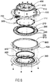
- is a schematic exploded view of a motor vehicle seat rotation mechanism of the present invention.
- Fig. 9
- is a schematic assembly view of a motor vehicle seat rotation mechanism of the present invention.
- Fig. 10
- is a schematic diagram showing the positional relationship of an upper ball and a lower ball in a motor vehicle seat rotation mechanism of the present invention.
- Fig. 11
- is a schematic diagram analysing the forces between an upper ball and a lower ball in a motor vehicle seat rotation mechanism of the present invention.
- Fig. 12
- is an enlarged schematic view of the region of an upper ball and a lower ball in a motor vehicle seat rotation mechanism of the present invention.
- Fig. 13
- is a top view of a locking device in a motor vehicle seat rotation mechanism of the present invention, when in a locked state.
- Fig. 14
- is an enlarged schematic view of region I in
fig. 13 . - Fig. 15
- is a three-dimensional schematic view of a locking device in a motor vehicle seat rotation mechanism of the present invention, when in a locked state.
- Fig. 16
- is an enlarged schematic view of region I in
fig. 15 . - Fig. 17
- is a schematic installation diagram of a locking device in a motor vehicle seat rotation mechanism of the present invention.
- Fig. 18
- is a structural schematic diagram of a locking device in a motor vehicle seat rotation mechanism of the present invention, viewed from one direction.
- Fig. 19
- is a structural schematic diagram of a locking device in a motor vehicle seat rotation mechanism of the present invention, viewed from another direction.
- Figs. 20a to 20c
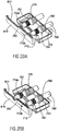
- are schematic procedural diagrams of a locking device in a motor vehicle seat rotation mechanism of the present invention, during entry into the locking hole.
- Fig. 21
- is a schematic diagram of a locking device in a motor vehicle seat rotation mechanism of the present invention, in a state of being unlocked.
- Fig. 22
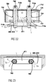
- is a schematic diagram of a state of locking between two locking pins and an obround locking hole in a locking device in a motor vehicle seat rotation mechanism of the present invention.
- Fig. 23
- is a schematic view of
fig. 22 in direction A. - Referring to
figs. 8 and9 , the motor vehicle seat rotation mechanism shown in the figures comprises a connectingplate 100, a movingplate 200, afixed plate 300, apress plate 400, anupper ball assembly 500, alower ball assembly 600 and alocking device 700. - An annular
upper ball track 410 is provided on thepress plate 400; an annular uppermiddle ball track 210 and an annular lowermiddle ball track 220 are provided on the movingplate 200; an annularlower ball track 310 is provided on the fixedplate 300. - The connecting
plate 100 is not only connected in a fixed manner to a seat (not shown in the figures), but also connected in a fixed manner to the movingplate 200 by means ofrivets 910, with the movingplate 200 being located below the connectingplate 100. The fixedplate 300 is connected to an upper slide rail (not shown in the figures) in a seat slide rail assembly, and is located below the movingplate 200. Thepress plate 400 is located above the movingplate 200 and connected in a fixed manner to the fixedplate 300 by means ofscrews 920. - The
upper ball track 410 on thepress plate 400 and the uppermiddle ball track 210 on the movingplate 200 are vertically opposite one another;upper balls 510 in theupper ball assembly 500 are located between theupper ball track 410 on thepress plate 400 and the uppermiddle ball track 210 on the movingplate 200, and are in rolling contact with both ball tracks. - The lower
middle ball track 220 on the movingplate 200 and thelower ball track 310 on the fixedplate 300 are vertically opposite one another;lower balls 610 in thelower ball assembly 600 are located between the lowermiddle ball track 220 on the movingplate 200 and thelower ball track 310 on the fixedplate 300, and are in rolling contact with both ball tracks. - A first characteristic of the motor vehicle seat rotation mechanism of the present invention is that it further comprises a lower
anti-detachment hook ring 800, located between the connectingplate 100 and the fixedplate 300 and fixed to the fixedplate 300. An annular loweranti-detachment hook 810, having an inverted U-shape, is provided at an inner edge of the loweranti-detachment hook ring 800; an annular upperanti-detachment hook 230, having a U-shape, is provided at an outer edge of the movingplate 200; the loweranti-detachment hook 810 is placed over the upperanti-detachment hook 230, achieving mutual engagement. When such a structure is subjected to a separating force, the components are in a state whereby the more they are pressed, the tighter they become, instead of a state whereby the more they are pulled, the more open they become, as in a conventional design. At the same time, thelower balls 610 are in a state whereby the more they are enclosed, the tighter they become, instead of having the tendency to come out of the lowermiddle ball track 220 on the movingplate 200 and thelower ball track 310 on the fixedplate 300. - A second characteristic of the present invention is: referring to
figs. 10 and11 , a radial separation between a perpendicular axis on which the centre of theupper ball 510 in theupper ball assembly 500 is located and a perpendicular axis on which the centre of thelower ball 610 in thelower ball assembly 600 is located, ΔA ≤ 0, whereas in the known art, ΔA > 0. An advantage of such a design is that under a pressing action, the relationship between theupper ball 510 and thelower ball 610 enables two forces F1 and F2, of equal magnitude but in opposite directions, to cancel each other out, avoiding elastic deformation of travel of the ball track under cantilever action, which would in turn affect the operating precision of the motor vehicle seat rotation mechanism of the present invention. - In particular, the tangent T510 of the
upper ball 510 is in parallel with the perpendicular axis P510 of theupper ball 510 and located radially outward of theupper ball 510 with respect to the centre axis CA (shown infigure 13 ) of the arrangement of the rotation mechanism. The tangent T610 of thelower ball 610 is in parallel with the perpendicular axis P610 of the lower ball and located radially inwards of thelower ball 610 with respect to the centre axis CA of the arrangement of the rotation mechanism. The radial distance ΔA between the tangents T510, T610 of theupper ball 510 and thelower ball 610 is equal or less than zero. Thus the adjacent upper andlower balls - In particular, in the case that ΔA = 0 than the tangents T510, T610 are identical, in particular congruent wherein the upper and
lower balls lower balls - A third characteristic of the present invention is: referring to
fig. 12 , when thepress plate 400 is tightened by the torque of the tightening screws 920, these apply a tightening force Fs which applies pressure downwards via theupper balls 510, pushing the movingplate 200 and thelower balls 610 towards the fixedplate 300, so that even in the case where the precision with which the ball track is worked has a certain error, theupper balls 510 andlower balls 610 can support each other during movement. - The
upper ball track 410 on thepress plate 400 is a flat surface ball track, a width thereof being one quarter of a diameter of theupper balls 510; this enables theupper balls 510 to have a certain amount of movement Δ1. - At the same time, the upper
middle ball track 210 on the movingplate 200 is a circular arc ball track; a radius R4 of the uppermiddle ball track 210 is greater than a radius R3 of theupper balls 510, so that under the action of the force Fs, theupper balls 510 force the movingplate 200 to move obliquely downwards to eliminate a tolerance, to a state of zero gap fitting. - The
lower ball track 310 on the fixedplate 300 of the present invention is a circular arc ball track; a radius R1 of thelower ball track 310 is less than a radius R2 of thelower balls 610, and when theupper balls 510 force thelower balls 610 to draw close to the centre of thelower ball track 310 of the fixedplate 300 by means of the lowermiddle ball track 220 on the movingplate 200, two-point contact is formed between eachlower ball 610 and thelower ball track 310. - A fourth characteristic of the present invention is: the locking
device 700, used for locking the fixedplate 300 to the movingplate 200 when adjustment of the motor vehicle rotation mechanism is complete, is mounted on the connectingplate 100 and located in a space between the connectingplate 100 and an outer edge of the loweranti-detachment hook ring 800; using the space between the connectingplate 100 and the outer edge of the loweranti-detachment hook ring 800 to mount thelocking device 700 in this way effectively reduces the height H of the motor vehicle seat rotation mechanism. - Referring to
figs. 13 to 19 , alocking device 700 shown in the figures comprises a lockingpin mounting box 710 at least having atop side 711, a firstlateral side 712 and a secondlateral side 713, and also comprises an unlockinghandle 720, two unlocking tension springs 730, 740, two lockingpins springs - The first
lateral side 712 and the secondlateral side 713 are disposed opposite each other; thetop side 711 is connected to a top edge of the firstlateral side 712; the firstlateral side 712 and the secondlateral side 713 are each provided with two lockingpin guide holes pin guide holes lateral side 712 and the secondlateral side 713 have a coaxial relationship with one-to-one correspondence. - The
locking pin 750 passes through the lockingpin guide hole 712a in the firstlateral side 712 and the lockingpin guide hole 713a in the secondlateral side 713; thelocking pin 760 passes through the lockingpin guide hole 712b in the firstlateral side 712 and the lockingpin guide hole 713b in the secondlateral side 713. -
Spring bearing bosses pins springs lateral side 712, and the other ends being in contact with thespring bearing bosses - First ends of the locking pins 750, 760, after passing through the first
lateral side 712, are connected to the unlockinghandle 720 via the unlocking tension springs 730, 740 respectively; second ends of the locking pins 750, 760 have a conical structure. A first end of the unlockinghandle 720 is hinged to thetop side 711 of the lockingpin mounting box 710. - A locking
device mounting gap 110 is provided in a certain position on an outer periphery of the connectingplate 100; thetop side 711 in thelocking device 700 is inserted into the lockingdevice mounting gap 110 and fastened by means of bolts 930. Anobround locking hole 811 is provided at a suitable position of the loweranti-detachment hook 810 on the loweranti-detachment hook ring 800; the second ends of the locking pins 750, 760, after passing through the secondlateral side 713, are simultaneously inserted into theobround locking hole 811. - Having the locking pins 750, 760 located in the space between the connecting
plate 100 and the outer edge of the loweranti-detachment hook ring 800 can further reduce the height H of the motor vehicle seat rotation mechanism. - When it is necessary to lock the seat to prevent rotation thereof, the locking pins 750, 760 in the
locking device 700 are inserted into thelocking hole 811 in the loweranti-detachment hook ring 800, to achieve locking between the connectingplate 100 and the loweranti-detachment hook ring 800. Since the connectingplate 100 is connected in a fixed manner to the movingplate 200, and the loweranti-detachment hook ring 800 is connected in a fixed manner to the fixedplate 300, locking between the movingplate 200 and the fixedplate 300 can be achieved. - When it is necessary to rotate the seat, the unlocking
handle 720 is lifted upward, and the two lockingpins hole 811 in the loweranti-detachment hook ring 800, by means of the two unlocking tension springs 730, 740. After releasing the unlockinghandle 720, the two lockingpins locking hole 811 in the loweranti-detachment hook ring 800 to achieve locking. The two unlocking tension springs 730, 740 drive the unlockinghandle 720 to its original position. - Referring to
fig. 16 , the present invention changes the claw-type locking in the prior art to an arrangement in which the two lockingpins locking hole 811 in the loweranti-detachment hook ring 800 to achieve locking. An advantage of this arrangement is that a hole-and-shaft fit is the form that is most convenient for machining and matching, and satisfactory precision can be attained relatively cheaply. - The two locking
pins - Referring to
figs. 20a to 20c , in a rotating state, the second ends of the two lockingpins anti-detachment hook 810 on the loweranti-detachment hook ring 800; when a locking position is reached, the lockingpin 750 rotates to the position of theobround locking hole 811 first, and is inserted into theobround locking hole 811 under the pushing action of thelocking spring 770; as the locking device continues to rotate relative to the fixedplate 300, the lockingpin 760 also rotates to the position of theobround locking hole 811, and is inserted into theobround locking hole 811 under the pushing action of thelocking spring 780. Once the second ends of both lockingpins obround locking hole 811, thelocking device 700 can no longer move relative to the fixedplate 300, so locking is achieved. - Referring to
fig. 21 , the present invention changes the rotary handle in the prior art to the unlockinghandle 720 which is lifted upward; the extension and retraction of the two lockingpins handle 720; the unlockinghandle 720 is lifted manually; the unlockinghandle 720 rotates anticlockwise around a hinge shaft 721 of the unlocking handle and thetop side 711; and the unlockinghandle 720 pulls the two lockingpins obround locking hole 811. When the unlockinghandle 720 is dropped, the two lockingpins locking hole 811 in the loweranti-detachment hook ring 800 to achieve locking; the structure is very simple, and the pulling-up of the unlockinghandle 720 is more in conformity with the operating habits of users. - Referring to
figs. 22 and 23 , the second ends of the two locking pins 750, 760 both have a conical structure; supposing that a length between two arc edges Ea, Eb at two ends of the obround locking hole 811 is L, a length of a line connecting guide points C, C' of the two locking pins 750, 760 is 0.8 mm less than the value of L, cone-shape starting points of the two locking pins 750, 760 are b, b', a length of a line connecting the cone-shape starting points b, b' of the two locking pins 750, 760 is 0.5 mm less than the value of L, cone-shape ending points of the two locking pins 750, 760 are a, a', a length of a line connecting the cone-shape end points a, a' of the two locking pins 750, 760 is 1.2 mm greater than the value of L; thus, under the combined action of the two locking pins 750, 760, it can be ensured that some point between the cone-shape starting points b, b' and the cone-shape ending points a, a' of the two locking pins 750, 760 will be in tight contact with the arc edges Ea, Eb at the two ends of the obround locking hole 811, i.e. in a "zero" gap fit, so gaps are eliminated. -
- 100
- connecting plate
- 110
- mounting gap
- 200
- moving plate
- 210
- annular upper middle ball track
- 220
- annular lower middle ball track
- 230
- annular upper anti-detachment hook
- 300
- fixed plate
- 310
- annular lower ball track
- 400
- press plate
- 410
- upper ball track
- 500
- upper ball assembly
- 510
- upper balls
- 600
- lower ball assembly
- 610
- lower balls
- 700
- locking device
- 710
- locking pin mounting box
- 711
- top side
- 712
- first lateral side
- 712a, 712b, 713a, 713b
- locking pin guide holes
- 713
- second lateral side
- 720
- unlocking handle
- 730, 740
- unlocking tension springs
- 750, 760
- locking pins
- 751, 761
- spring bearing bosses
- 770, 780
- locking springs
- 800
- lower anti-detachment hook ring
- 810
- annular lower anti-detachment hook
- 811
- obround locking hole
- 910
- rivets
- 920
- screws
- 930
- bolts
- a, a'
- cone-shape ending points
- b, b'
- cone-shape starting points
- c, c'
- connecting guide points
- Ea, Eb
- arc edge
- Fs
- tightening force
- H
- height
- L
- length
- R3, R4
- radius
Claims (15)
- Motor vehicle seat rotation mechanism, comprising:a connecting plate (100) connected to a seat;a moving plate (200), located below the connecting plate (100) andconnected in a fixed manner to the connecting plate (100);a fixed plate (300) located below the moving plate (200), the fixed plate (300) being connected to an upper slide rail in a slide rail assembly of the seat;a press plate (400), located above the moving plate (200) andconnected in a fixed manner to the fixed plate (300);an upper ball assembly (500) located between the press plate (400) and the moving plate (200);a lower ball assembly (600) located between the moving plate (200) and the fixed plate (300); characterized by further comprising:a lower anti-detachment hook ring (800), located between the connecting plate (100) and the fixed plate (300), and fixed to the fixed plate (300), with an annular lower anti-detachment hook (810) being provided at an inner edge of the lower anti-detachment hook ring (800), and an annular upper anti-detachment hook (230) being provided at an outer edge of the moving plate (200), the lower anti-detachment hook (810) and the upper anti-detachment hook (230) being engaged with each other.
- Motor vehicle seat rotation mechanism according to Claim 1, characterized in that the lower anti-detachment hook (810) has an inverted U-shape, the upper anti-detachment hook (230) has a U-shape, and the lower anti-detachment hook (810) having the inverted U-shape is placed over the upper anti-detachment hook (230) having the U-shape.
- Motor vehicle seat rotation mechanism according to claim 1 or 2, characterized in that a radial separation (ΔA) between a perpendicular axis on which the centre of an upper ball (510) in the upper ball assembly (500) is located, and a perpendicular axis on which the centre of a lower ball (610) in the lower ball assembly (600) is located, is less equal to or less than zero.
- Motor vehicle seat rotation mechanism according to anyone of the preceding claims, characterized in that an upper ball track (410) is provided on the press plate (400), an upper middle ball track (210) and a lower middle ball track (220) are provided on the moving plate (200), and a lower ball track is provided on the fixed plate (300), wherein the upper ball track on the press plate (400) and the upper middle ball track (210) on the moving plate (200) are vertically opposite one another.
- Motor vehicle seat rotation mechanism according to claim 4, wherein an upper ball (510) in the upper ball assembly (500) is located between the upper ball track (410) on the press plate (400) and the upper middle ball track (210) on the moving plate (200), and in rolling contact with the upper ball track (410) on the press plate (400) and the upper middle ball track (210) on the moving plate (200).
- Motor vehicle seat rotation mechanism according to anyone of the preceding claims, wherein the lower middle ball track (220) on the moving plate (200) and the lower ball track on the fixed plate (300) are vertically opposite one another, and a lower ball (610) in the lower ball assembly (600) is located between the lower middle ball track (220) on the moving plate (200) and the lower ball track on the fixed plate (300), and in rolling contact with the lower middle ball track (220) on the moving plate (200) and the lower ball track on the fixed plate (300).
- Motor vehicle seat rotation mechanism according to claim 5 or 6, wherein the upper ball track (410) on the press plate (400) is a flat surface ball track, a width thereof being one quarter of a diameter of the upper ball (510).
- Motor vehicle seat rotation mechanism according to claim 6 or 7, wherein the upper middle ball track (210) on the moving plate (200) is a circular arc ball track, a radius of the upper middle ball track (210) being greater than a radius of the upper ball (510); and the lower ball track on the fixed plate (300) is a circular arc ball track, a radius of the lower ball track being less than a radius of the lower ball (610), such that two-point contact is formed between the lower ball (610) and the lower ball track.
- Motor vehicle seat rotation mechanism according to any one of the preceding claims 1 to 8, characterized in that the motor vehicle seat rotation mechanism further comprises a locking device (700), for locking the fixed plate (300) to the moving plate (200) when adjustment of the motor vehicle rotation mechanism is complete; the locking device is mounted on the connecting plate (100) and located in a space between the connecting plate (100) and an outer edge of the lower anti-detachment hook ring (800).
- Motor vehicle seat rotation mechanism according to Claim 9, characterized in that the locking device at least comprises a locking pin located in the space between the connecting plate (750, 760) and the outer edge of the lower anti-detachment hook ring (800), and a locking hole is provided in the lower anti-detachment hook ring (800); when it is necessary to lock the seat to prevent rotation thereof, the locking pin (750, 760) in the locking device is inserted into the locking hole in the lower anti-detachment hook ring (800), to achieve locking between the connecting plate (100) and the lower anti-detachment hook ring (800), and in turn achieve locking between the moving plate (200) and the fixed plate (300); when it is necessary to rotate the seat, the locking pin in the locking device is pulled out of the locking hole in the lower anti-detachment hook ring (800).
- Motor vehicle seat rotation mechanism according to claim 9 or 10, characterized in that the locking device further comprises a locking pin mounting box (710) at least having a top side (711), a first lateral side (712) and a second lateral side (713), and also comprises an unlocking handle (720) and at least one unlocking tension spring (730, 740), with the first lateral side (712) and the second lateral side (713) being disposed opposite each other, the top side (711) being connected to a top edge of the first lateral side (712), the first lateral side (712) and the second lateral side (713) each being provided with at least one locking pin guide hole (712a, 712b, 713a, 713b), and the locking pin guide holes (712a, 712b, 713a, 713b) in the first lateral side (712) and the second lateral side (713) having a coaxial relationship with one-to-one correspondence; the locking pin (750, 760) passes through the corresponding locking pin guide holes (712a, 712b, 713a, 713b) in the first lateral side (712) and the second lateral side (713), a spring bearing boss (751, 761) is provided in a middle position of the locking pin (750, 760) and a locking spring (770, 780) surrounds the locking pin (750, 760), with the locking spring (770, 780) having one end in contact with the first lateral side (712) and another end in contact with the spring bearing boss (751, 761); a first end of the locking pin (750, 760), after passing through the first lateral side (712), is connected to the unlocking handle (720) by means of the unlocking tension spring (730, 740), and a second end of the locking pin (750, 760), after passing through the second lateral side (713), is inserted into the locking hole in the lower anti-detachment hook ring (800) in a locked state; a first end of the unlocking handle (720) is hinged to the top side (711) of the locking pin mounting box (710), and the top side of the locking pin mounting box (710) is mounted on the connecting plate (100) in a fixed manner.
- Motor vehicle seat rotation mechanism according to claim 11, characterized in that the second end of the locking pin (750, 760) has a conical structure.
- Motor vehicle seat rotation mechanism according to Claim 12, characterized in that there are two said locking pins (750, 760), the locking hole (811) in the lower anti-detachment hook ring (800) is an obround locking hole (811), the two locking pins (750, 760) are simultaneously inserted into the obround locking hole (811), and conical surfaces on the two locking pins (750, 760) are in tight contact with arc edges at two ends of the obround locking hole (811).
- Motor vehicle seat rotation mechanism, comprising:a connecting plate (100) connected to a seat;a moving plate (200), located below the connecting plate (100) andconnected in a fixed manner to the connecting plate (100);a fixed plate (300) located below the moving plate (200), the fixed plate (300) being connected to an upper slide rail in a slide rail assembly of the seat;a press plate (400), located above the moving plate (200) andconnected in a fixed manner to the fixed plate (300);an upper ball assembly (500) located between the press plate (400) and the moving plate (200);a lower ball assembly (600) located between the moving plate (200) and the fixed plate (300); characterized in that:a locking device (700), used for locking the fixed plate (300) to the moving plate (200) when adjustment of the motor vehicle rotation mechanism is complete, is mounted on the connecting plate (100) and located in a space between the connecting plate (100) and an outer edge of the lower anti-detachment hook ring (800); using the space between the connecting plate (100) and the outer edge of the lower anti-detachment hook ring (800).
- Motor vehicle seat rotation mechanism, comprising:a connecting plate (100) connected to a seat;a moving plate (200), located below the connecting plate (100) andconnected in a fixed manner to the connecting plate (100);a fixed plate (300) located below the moving plate (200), the fixed plate (300) being connected to an upper slide rail in a slide rail assembly of the seat;a press plate (400), located above the moving plate (200) andconnected in a fixed manner to the fixed plate (300);an upper ball assembly (500) located between the press plate (400) and the moving plate (200);a lower ball assembly (600) located between the moving plate (200) and the fixed plate (300); characterized in that:a radial separation (ΔA) between a perpendicular axis on which the centre of the upper ball (510) in the upper ball assembly (500) is located and a perpendicular axis on which the centre of the lower ball (610) in the lower ball assembly (600) is located, is equal to or less than zero.
Applications Claiming Priority (1)
| Application Number | Priority Date | Filing Date | Title |
|---|---|---|---|
| CN201711218807.2A CN107953806B (en) | 2017-11-28 | 2017-11-28 | Automobile seat rotating mechanism |
Publications (2)
| Publication Number | Publication Date |
|---|---|
| EP3489079A1 true EP3489079A1 (en) | 2019-05-29 |
| EP3489079B1 EP3489079B1 (en) | 2021-09-08 |
Family
ID=61962313
Family Applications (1)
| Application Number | Title | Priority Date | Filing Date |
|---|---|---|---|
| EP18208624.9A Active EP3489079B1 (en) | 2017-11-28 | 2018-11-27 | Motor vehicle seat rotation mechanism |
Country Status (4)
| Country | Link |
|---|---|
| US (1) | US10688889B2 (en) |
| EP (1) | EP3489079B1 (en) |
| JP (1) | JP6650989B2 (en) |
| CN (1) | CN107953806B (en) |
Cited By (2)
| Publication number | Priority date | Publication date | Assignee | Title |
|---|---|---|---|---|
| CN110626230A (en) * | 2019-10-31 | 2019-12-31 | 湖北航嘉麦格纳座椅系统有限公司 | Car seat and seat swivel mechanism |
| DE102019124672B3 (en) * | 2019-09-13 | 2021-02-04 | Isringhausen Gmbh & Co. Kg | Rotary unit for a vehicle seat that can rotate about its vertical axis, crash hook for such a rotary unit and rotatable vehicle seat |
Families Citing this family (34)
| Publication number | Priority date | Publication date | Assignee | Title |
|---|---|---|---|---|
| CN207725260U (en) * | 2017-11-28 | 2018-08-14 | 延锋安道拓座椅有限公司 | A kind of locking system |
| CN209474126U (en) * | 2018-07-27 | 2019-10-11 | 延锋安道拓座椅有限公司 | A kind of rotary seat gapless lockable mechanism |
| CN108968465B (en) * | 2018-07-27 | 2024-07-30 | 延锋国际座椅系统有限公司 | Seat rotating locking mechanism |
| CN109050356A (en) * | 2018-08-10 | 2018-12-21 | 重庆杜米亚柯科技有限公司 | A kind of automobile seat rotary table structure |
| CN109823239B (en) | 2019-02-14 | 2023-03-10 | 延锋国际座椅系统有限公司 | Electric rotating device for automobile seat |
| CN109677302B (en) * | 2019-02-14 | 2020-08-28 | 延锋安道拓座椅有限公司 | Swivel device for vehicle seat |
| CN110406434B (en) * | 2019-06-17 | 2024-06-07 | 广汽零部件有限公司 | Automobile seat slide rail mechanism |
| CN110384355B (en) * | 2019-07-19 | 2022-05-27 | 开封大学 | A deformable and combined work seat |
| CN110435498B (en) * | 2019-09-23 | 2024-04-19 | 麦格纳汽车技术(上海)有限公司徐汇分公司 | Seat rotating mechanism capable of adjusting rotating force |
| CN113619454A (en) * | 2020-05-06 | 2021-11-09 | 威马智慧出行科技(上海)有限公司 | Seat structure and car |
| CN112026625B (en) * | 2020-09-10 | 2021-07-23 | 惠安县螺阳林飞燕汽车维修中心 | Outdoor breakdown van |
| US11772517B2 (en) | 2020-11-09 | 2023-10-03 | Ford Global Technologies, Llc | Vehicular system capable of adjusting a passenger compartment from a child seat arrangement to a second arrangement |
| US11772519B2 (en) | 2020-11-09 | 2023-10-03 | Ford Global Technologies, Llc | Vehicular system capable of adjusting a passenger compartment from a first arrangement to a child seat arrangement |
| US12257932B2 (en) | 2020-11-09 | 2025-03-25 | Ford Global Technologies, Llc | Exterior imager utilized in adjusting a passenger compartment arrangement |
| US11731535B2 (en) | 2020-11-09 | 2023-08-22 | Ford Global Technologies, Llc | Vehicular system capable of adjusting a passenger compartment from a child care arrangement to a second arrangement |
| US11772520B2 (en) | 2020-11-09 | 2023-10-03 | Ford Global Technologies, Llc | Remote notification and adjustment of a passenger compartment arrangement |
| US12077068B2 (en) | 2020-11-09 | 2024-09-03 | Ford Global Technologies, Llc | Authorization-based adjustment of passenger compartment arrangement |
| US11904732B2 (en) | 2020-11-09 | 2024-02-20 | Ford Global Technologies, Llc | Vehicular system capable of adjusting a passenger compartment from a first arrangement to a child care arrangement |
| CN112674530A (en) * | 2021-01-25 | 2021-04-20 | 嘉兴市领地家具用品有限公司 | Seat frame |
| CN112848979A (en) * | 2021-02-19 | 2021-05-28 | 上海东尚机械科技有限责任公司 | Manual rotating system of car seat |
| CN113147529B (en) * | 2021-04-25 | 2024-08-16 | 长春一汽富维安道拓汽车金属零部件有限公司 | Manual unlocking automobile rotary seat |
| CN113135129B (en) * | 2021-05-14 | 2022-09-27 | 东风汽车集团股份有限公司 | But manual electric regulation's rotatory seat and car |
| US12104744B2 (en) * | 2022-06-01 | 2024-10-01 | Jinyan Duan | Turner apparatus |
| US12196358B2 (en) * | 2021-09-26 | 2025-01-14 | Xiaoling CHE | Rotating assembly |
| CN113829966A (en) * | 2021-11-08 | 2021-12-24 | 重庆飞适动力汽车座椅部件有限公司 | A inside and outside slide rail anticreep device for vehicle seat |
| US12128807B2 (en) | 2022-03-21 | 2024-10-29 | Ford Global Technologies, Llc | Seat-mounted work surface |
| US12030409B2 (en) | 2022-03-21 | 2024-07-09 | Ford Global Technologies, Llc | Seating assembly with swivel capability |
| US11919361B2 (en) | 2022-03-21 | 2024-03-05 | Ford Global Technologies, Llc | Vehicle floor panel |
| KR102710068B1 (en) * | 2022-04-11 | 2024-09-26 | 대원산업 주식회사 | Swivel seat for vehicle |
| USD1110749S1 (en) * | 2022-06-27 | 2026-02-03 | Williams-Sonoma, Inc. | Seat and backrest |
| US11904737B2 (en) | 2022-07-15 | 2024-02-20 | Ford Global Technologies, Llc | Seating assembly with swivel capability |
| CN115384375A (en) * | 2022-09-29 | 2022-11-25 | 湖北中航精机科技有限公司 | A kind of headrest structure and seat |
| KR102711101B1 (en) * | 2023-01-27 | 2024-09-30 | 현대트랜시스 주식회사 | Device for swivelling seat of vehicle |
| CN220764153U (en) * | 2023-09-12 | 2024-04-12 | 湖北中航精机科技有限公司 | Seat carousel mechanism and vehicle |
Citations (7)
| Publication number | Priority date | Publication date | Assignee | Title |
|---|---|---|---|---|
| US3338622A (en) * | 1965-12-08 | 1967-08-29 | Chrysler Corp | Swivel seat for motor vehicle |
| DE4203150A1 (en) * | 1992-02-05 | 1993-08-12 | Keiper Recaro Gmbh Co | Rotary frame for supporting vehicle seat - has set of curved upper and lower spaced safety carrier rails |
| CN1188053A (en) | 1996-12-16 | 1998-07-22 | 丰田车体株式会社 | Seat rotating device |
| CN1189343C (en) | 2000-08-31 | 2005-02-16 | 约翰逊控制自动化系统株式会社 | Rotation regulating mechanism for vehicle seat |
| US20080163717A1 (en) * | 2003-08-27 | 2008-07-10 | Weber James L | Locking Mechanism For Seat Track Assembly |
| CN103863151A (en) | 2012-12-18 | 2014-06-18 | 格拉默股份有限公司 | Commercial vehicle seat having a locking member |
| CN106427682A (en) | 2016-11-24 | 2017-02-22 | 江苏忠明祥和精工股份有限公司 | Turnplate for automobile seat |
Family Cites Families (12)
| Publication number | Priority date | Publication date | Assignee | Title |
|---|---|---|---|---|
| CN2253143Y (en) * | 1995-06-06 | 1997-04-30 | 上海旭卡机械电器有限公司 | Improved revolvable seat |
| JP3451910B2 (en) | 1996-12-16 | 2003-09-29 | トヨタ車体株式会社 | Rotating device for vehicle seat |
| US6021989A (en) * | 1996-12-16 | 2000-02-08 | Toyota Shatai Kabushiki Kaisha | Swivel assembly of a vehicle seat |
| JPH10217811A (en) * | 1997-02-10 | 1998-08-18 | Toyota Auto Body Co Ltd | Seat rotating device |
| JP3570363B2 (en) | 2000-08-31 | 2004-09-29 | ジョンソン コントロールズ オートモーティブ システムズ株式会社 | Vehicle seat rotation adjustment mechanism |
| JP4305675B2 (en) | 2007-03-02 | 2009-07-29 | トヨタ車体株式会社 | Vehicle seat |
| DE102012112523B4 (en) * | 2012-12-18 | 2020-11-12 | Grammer Aktiengesellschaft | Commercial vehicle seat with rotatable seat part |
| DE102012112527B3 (en) * | 2012-12-18 | 2014-06-05 | Grammer Ag | Commercial vehicle seat with integrated rotary adjustment device |
| DE102012112528B4 (en) * | 2012-12-18 | 2014-09-18 | Grammer Ag | Commercial vehicle seat with a Drehverstelleinrichtung overload protection unit |
| CN203974597U (en) * | 2014-07-18 | 2014-12-03 | 重庆延锋江森汽车部件系统有限公司 | Sliding rail of automobile seat |
| CN105416104B (en) * | 2015-12-14 | 2018-02-16 | 襄阳寒桦精机有限公司 | A kind of Vehicular seat device |
| CN206186835U (en) | 2016-11-24 | 2017-05-24 | 江苏忠明祥和精工股份有限公司 | Carousel for car seat |
-
2017
- 2017-11-28 CN CN201711218807.2A patent/CN107953806B/en active Active
-
2018
- 2018-11-26 JP JP2018219925A patent/JP6650989B2/en active Active
- 2018-11-27 EP EP18208624.9A patent/EP3489079B1/en active Active
- 2018-11-27 US US16/201,010 patent/US10688889B2/en active Active
Patent Citations (8)
| Publication number | Priority date | Publication date | Assignee | Title |
|---|---|---|---|---|
| US3338622A (en) * | 1965-12-08 | 1967-08-29 | Chrysler Corp | Swivel seat for motor vehicle |
| DE4203150A1 (en) * | 1992-02-05 | 1993-08-12 | Keiper Recaro Gmbh Co | Rotary frame for supporting vehicle seat - has set of curved upper and lower spaced safety carrier rails |
| CN1188053A (en) | 1996-12-16 | 1998-07-22 | 丰田车体株式会社 | Seat rotating device |
| CN1189343C (en) | 2000-08-31 | 2005-02-16 | 约翰逊控制自动化系统株式会社 | Rotation regulating mechanism for vehicle seat |
| US20080163717A1 (en) * | 2003-08-27 | 2008-07-10 | Weber James L | Locking Mechanism For Seat Track Assembly |
| CN103863151A (en) | 2012-12-18 | 2014-06-18 | 格拉默股份有限公司 | Commercial vehicle seat having a locking member |
| CN103863151B (en) | 2012-12-18 | 2017-01-04 | 格拉默股份有限公司 | There is the commercial vehicle seat of locking member |
| CN106427682A (en) | 2016-11-24 | 2017-02-22 | 江苏忠明祥和精工股份有限公司 | Turnplate for automobile seat |
Cited By (4)
| Publication number | Priority date | Publication date | Assignee | Title |
|---|---|---|---|---|
| DE102019124672B3 (en) * | 2019-09-13 | 2021-02-04 | Isringhausen Gmbh & Co. Kg | Rotary unit for a vehicle seat that can rotate about its vertical axis, crash hook for such a rotary unit and rotatable vehicle seat |
| WO2021047921A2 (en) | 2019-09-13 | 2021-03-18 | Isringhausen Gmbh & Co. Kg | Rotary unit for a vehicle seat that can be rotated about its vertical axis, crash hook for a rotary unit of this type, and rotatable vehicle seat |
| WO2021047921A3 (en) * | 2019-09-13 | 2021-05-06 | Isringhausen Gmbh & Co. Kg | Rotary unit for a vehicle seat that can be rotated about its vertical axis, crash hook for a rotary unit of this type, and rotatable vehicle seat |
| CN110626230A (en) * | 2019-10-31 | 2019-12-31 | 湖北航嘉麦格纳座椅系统有限公司 | Car seat and seat swivel mechanism |
Also Published As
| Publication number | Publication date |
|---|---|
| JP2019099144A (en) | 2019-06-24 |
| CN107953806A (en) | 2018-04-24 |
| US20190160977A1 (en) | 2019-05-30 |
| CN107953806B (en) | 2020-04-07 |
| EP3489079B1 (en) | 2021-09-08 |
| JP6650989B2 (en) | 2020-02-19 |
| US10688889B2 (en) | 2020-06-23 |
Similar Documents
| Publication | Publication Date | Title |
|---|---|---|
| EP3489079B1 (en) | Motor vehicle seat rotation mechanism | |
| EP3489080B1 (en) | Locking device and motor vehicle seat rotation mechanism | |
| US8720999B2 (en) | Fitting for a vehicle seat | |
| EP4194240B1 (en) | Locking mechanism, battery bracket, electric vehicle, and method for locking and unlocking battery pack | |
| US5873630A (en) | Rotary-cam type reclining device | |
| US7926858B2 (en) | Lock device | |
| US7703852B2 (en) | Heavy duty reclining mechanism for vehicle seats | |
| EP2646281B1 (en) | Fitting for a vehicle seat | |
| EP3103653A1 (en) | Double-lock caster | |
| EP3246245B1 (en) | Folding wing tip and rotating locking member | |
| KR20150130306A (en) | Disc recliner with tapered pin cam surface | |
| US20190300178A1 (en) | Payload attachment fitting and methods to use the same | |
| US20100219037A1 (en) | Bidirectional self-locking device | |
| US7810886B2 (en) | Lock device and seat reclining apparatus | |
| US8960797B2 (en) | Latch fitting for locking two vehicle components | |
| CN103534137A (en) | Dual cam recliner | |
| CN101554850B (en) | Seat arrangement with such a motor vehicle seat with a seat back and seat arrangement with such a motor vehicle seat | |
| EP3931041A2 (en) | Detent fitting for a vehicle seat | |
| CN102650176A (en) | Push-button type handle | |
| US10787102B2 (en) | Recliner mechanism | |
| CN202611342U (en) | Button type spring handle | |
| US20230193664A1 (en) | Door latch jamming assembly | |
| US20130051899A1 (en) | Detent fitting for locking two vehicle parts | |
| US3002369A (en) | Releasable fastening devices | |
| HK40088064B (en) | Locking mechanism, battery bracket, electric vehicle, and method for locking and unlocking battery pack |
Legal Events
| Date | Code | Title | Description |
|---|---|---|---|
| PUAI | Public reference made under article 153(3) epc to a published international application that has entered the european phase |
Free format text: ORIGINAL CODE: 0009012 |
|
| STAA | Information on the status of an ep patent application or granted ep patent |
Free format text: STATUS: THE APPLICATION HAS BEEN PUBLISHED |
|
| AK | Designated contracting states |
Kind code of ref document: A1 Designated state(s): AL AT BE BG CH CY CZ DE DK EE ES FI FR GB GR HR HU IE IS IT LI LT LU LV MC MK MT NL NO PL PT RO RS SE SI SK SM TR |
|
| AX | Request for extension of the european patent |
Extension state: BA ME |
|
| STAA | Information on the status of an ep patent application or granted ep patent |
Free format text: STATUS: REQUEST FOR EXAMINATION WAS MADE |
|
| 17P | Request for examination filed |
Effective date: 20191129 |
|
| RBV | Designated contracting states (corrected) |
Designated state(s): AL AT BE BG CH CY CZ DE DK EE ES FI FR GB GR HR HU IE IS IT LI LT LU LV MC MK MT NL NO PL PT RO RS SE SI SK SM TR |
|
| STAA | Information on the status of an ep patent application or granted ep patent |
Free format text: STATUS: EXAMINATION IS IN PROGRESS |
|
| 17Q | First examination report despatched |
Effective date: 20200602 |
|
| GRAP | Despatch of communication of intention to grant a patent |
Free format text: ORIGINAL CODE: EPIDOSNIGR1 |
|
| STAA | Information on the status of an ep patent application or granted ep patent |
Free format text: STATUS: GRANT OF PATENT IS INTENDED |
|
| INTG | Intention to grant announced |
Effective date: 20210413 |
|
| GRAS | Grant fee paid |
Free format text: ORIGINAL CODE: EPIDOSNIGR3 |
|
| GRAA | (expected) grant |
Free format text: ORIGINAL CODE: 0009210 |
|
| STAA | Information on the status of an ep patent application or granted ep patent |
Free format text: STATUS: THE PATENT HAS BEEN GRANTED |
|
| AK | Designated contracting states |
Kind code of ref document: B1 Designated state(s): AL AT BE BG CH CY CZ DE DK EE ES FI FR GB GR HR HU IE IS IT LI LT LU LV MC MK MT NL NO PL PT RO RS SE SI SK SM TR |
|
| REG | Reference to a national code |
Ref country code: GB Ref legal event code: FG4D |
|
| REG | Reference to a national code |
Ref country code: CH Ref legal event code: EP Ref country code: AT Ref legal event code: REF Ref document number: 1428303 Country of ref document: AT Kind code of ref document: T Effective date: 20210915 |
|
| REG | Reference to a national code |
Ref country code: DE Ref legal event code: R096 Ref document number: 602018023173 Country of ref document: DE |
|
| REG | Reference to a national code |
Ref country code: IE Ref legal event code: FG4D |
|
| REG | Reference to a national code |
Ref country code: LT Ref legal event code: MG9D |
|
| REG | Reference to a national code |
Ref country code: NL Ref legal event code: MP Effective date: 20210908 |
|
| PG25 | Lapsed in a contracting state [announced via postgrant information from national office to epo] |
Ref country code: SE Free format text: LAPSE BECAUSE OF FAILURE TO SUBMIT A TRANSLATION OF THE DESCRIPTION OR TO PAY THE FEE WITHIN THE PRESCRIBED TIME-LIMIT Effective date: 20210908 Ref country code: RS Free format text: LAPSE BECAUSE OF FAILURE TO SUBMIT A TRANSLATION OF THE DESCRIPTION OR TO PAY THE FEE WITHIN THE PRESCRIBED TIME-LIMIT Effective date: 20210908 Ref country code: HR Free format text: LAPSE BECAUSE OF FAILURE TO SUBMIT A TRANSLATION OF THE DESCRIPTION OR TO PAY THE FEE WITHIN THE PRESCRIBED TIME-LIMIT Effective date: 20210908 Ref country code: ES Free format text: LAPSE BECAUSE OF FAILURE TO SUBMIT A TRANSLATION OF THE DESCRIPTION OR TO PAY THE FEE WITHIN THE PRESCRIBED TIME-LIMIT Effective date: 20210908 Ref country code: FI Free format text: LAPSE BECAUSE OF FAILURE TO SUBMIT A TRANSLATION OF THE DESCRIPTION OR TO PAY THE FEE WITHIN THE PRESCRIBED TIME-LIMIT Effective date: 20210908 Ref country code: NO Free format text: LAPSE BECAUSE OF FAILURE TO SUBMIT A TRANSLATION OF THE DESCRIPTION OR TO PAY THE FEE WITHIN THE PRESCRIBED TIME-LIMIT Effective date: 20211208 Ref country code: BG Free format text: LAPSE BECAUSE OF FAILURE TO SUBMIT A TRANSLATION OF THE DESCRIPTION OR TO PAY THE FEE WITHIN THE PRESCRIBED TIME-LIMIT Effective date: 20211208 Ref country code: LT Free format text: LAPSE BECAUSE OF FAILURE TO SUBMIT A TRANSLATION OF THE DESCRIPTION OR TO PAY THE FEE WITHIN THE PRESCRIBED TIME-LIMIT Effective date: 20210908 |
|
| REG | Reference to a national code |
Ref country code: AT Ref legal event code: MK05 Ref document number: 1428303 Country of ref document: AT Kind code of ref document: T Effective date: 20210908 |
|
| PG25 | Lapsed in a contracting state [announced via postgrant information from national office to epo] |
Ref country code: LV Free format text: LAPSE BECAUSE OF FAILURE TO SUBMIT A TRANSLATION OF THE DESCRIPTION OR TO PAY THE FEE WITHIN THE PRESCRIBED TIME-LIMIT Effective date: 20210908 Ref country code: GR Free format text: LAPSE BECAUSE OF FAILURE TO SUBMIT A TRANSLATION OF THE DESCRIPTION OR TO PAY THE FEE WITHIN THE PRESCRIBED TIME-LIMIT Effective date: 20211209 |
|
| PG25 | Lapsed in a contracting state [announced via postgrant information from national office to epo] |
Ref country code: AT Free format text: LAPSE BECAUSE OF FAILURE TO SUBMIT A TRANSLATION OF THE DESCRIPTION OR TO PAY THE FEE WITHIN THE PRESCRIBED TIME-LIMIT Effective date: 20210908 |
|
| PG25 | Lapsed in a contracting state [announced via postgrant information from national office to epo] |
Ref country code: IS Free format text: LAPSE BECAUSE OF FAILURE TO SUBMIT A TRANSLATION OF THE DESCRIPTION OR TO PAY THE FEE WITHIN THE PRESCRIBED TIME-LIMIT Effective date: 20220108 Ref country code: SM Free format text: LAPSE BECAUSE OF FAILURE TO SUBMIT A TRANSLATION OF THE DESCRIPTION OR TO PAY THE FEE WITHIN THE PRESCRIBED TIME-LIMIT Effective date: 20210908 Ref country code: SK Free format text: LAPSE BECAUSE OF FAILURE TO SUBMIT A TRANSLATION OF THE DESCRIPTION OR TO PAY THE FEE WITHIN THE PRESCRIBED TIME-LIMIT Effective date: 20210908 Ref country code: RO Free format text: LAPSE BECAUSE OF FAILURE TO SUBMIT A TRANSLATION OF THE DESCRIPTION OR TO PAY THE FEE WITHIN THE PRESCRIBED TIME-LIMIT Effective date: 20210908 Ref country code: PT Free format text: LAPSE BECAUSE OF FAILURE TO SUBMIT A TRANSLATION OF THE DESCRIPTION OR TO PAY THE FEE WITHIN THE PRESCRIBED TIME-LIMIT Effective date: 20220110 Ref country code: PL Free format text: LAPSE BECAUSE OF FAILURE TO SUBMIT A TRANSLATION OF THE DESCRIPTION OR TO PAY THE FEE WITHIN THE PRESCRIBED TIME-LIMIT Effective date: 20210908 Ref country code: NL Free format text: LAPSE BECAUSE OF FAILURE TO SUBMIT A TRANSLATION OF THE DESCRIPTION OR TO PAY THE FEE WITHIN THE PRESCRIBED TIME-LIMIT Effective date: 20210908 Ref country code: EE Free format text: LAPSE BECAUSE OF FAILURE TO SUBMIT A TRANSLATION OF THE DESCRIPTION OR TO PAY THE FEE WITHIN THE PRESCRIBED TIME-LIMIT Effective date: 20210908 Ref country code: CZ Free format text: LAPSE BECAUSE OF FAILURE TO SUBMIT A TRANSLATION OF THE DESCRIPTION OR TO PAY THE FEE WITHIN THE PRESCRIBED TIME-LIMIT Effective date: 20210908 Ref country code: AL Free format text: LAPSE BECAUSE OF FAILURE TO SUBMIT A TRANSLATION OF THE DESCRIPTION OR TO PAY THE FEE WITHIN THE PRESCRIBED TIME-LIMIT Effective date: 20210908 |
|
| REG | Reference to a national code |
Ref country code: DE Ref legal event code: R097 Ref document number: 602018023173 Country of ref document: DE |
|
| RAP2 | Party data changed (patent owner data changed or rights of a patent transferred) |
Owner name: ADIENT US LLC |
|
| PG25 | Lapsed in a contracting state [announced via postgrant information from national office to epo] |
Ref country code: MC Free format text: LAPSE BECAUSE OF FAILURE TO SUBMIT A TRANSLATION OF THE DESCRIPTION OR TO PAY THE FEE WITHIN THE PRESCRIBED TIME-LIMIT Effective date: 20210908 |
|
| REG | Reference to a national code |
Ref country code: CH Ref legal event code: PL |
|
| PLBE | No opposition filed within time limit |
Free format text: ORIGINAL CODE: 0009261 |
|
| STAA | Information on the status of an ep patent application or granted ep patent |
Free format text: STATUS: NO OPPOSITION FILED WITHIN TIME LIMIT |
|
| REG | Reference to a national code |
Ref country code: DE Ref legal event code: R081 Ref document number: 602018023173 Country of ref document: DE Owner name: ADIENT US LLC, PLYMOUTH, US Free format text: FORMER OWNER: ADIENT ENGINEERING AND IP GMBH, 51399 BURSCHEID, DE |
|
| PG25 | Lapsed in a contracting state [announced via postgrant information from national office to epo] |
Ref country code: LU Free format text: LAPSE BECAUSE OF NON-PAYMENT OF DUE FEES Effective date: 20211127 Ref country code: DK Free format text: LAPSE BECAUSE OF FAILURE TO SUBMIT A TRANSLATION OF THE DESCRIPTION OR TO PAY THE FEE WITHIN THE PRESCRIBED TIME-LIMIT Effective date: 20210908 Ref country code: BE Free format text: LAPSE BECAUSE OF NON-PAYMENT OF DUE FEES Effective date: 20211130 |
|
| REG | Reference to a national code |
Ref country code: BE Ref legal event code: MM Effective date: 20211130 |
|
| 26N | No opposition filed |
Effective date: 20220609 |
|
| PG25 | Lapsed in a contracting state [announced via postgrant information from national office to epo] |
Ref country code: SI Free format text: LAPSE BECAUSE OF FAILURE TO SUBMIT A TRANSLATION OF THE DESCRIPTION OR TO PAY THE FEE WITHIN THE PRESCRIBED TIME-LIMIT Effective date: 20210908 Ref country code: LI Free format text: LAPSE BECAUSE OF NON-PAYMENT OF DUE FEES Effective date: 20211130 Ref country code: CH Free format text: LAPSE BECAUSE OF NON-PAYMENT OF DUE FEES Effective date: 20211130 |
|
| PG25 | Lapsed in a contracting state [announced via postgrant information from national office to epo] |
Ref country code: IE Free format text: LAPSE BECAUSE OF NON-PAYMENT OF DUE FEES Effective date: 20211127 |
|
| PG25 | Lapsed in a contracting state [announced via postgrant information from national office to epo] |
Ref country code: IT Free format text: LAPSE BECAUSE OF FAILURE TO SUBMIT A TRANSLATION OF THE DESCRIPTION OR TO PAY THE FEE WITHIN THE PRESCRIBED TIME-LIMIT Effective date: 20210908 |
|
| PG25 | Lapsed in a contracting state [announced via postgrant information from national office to epo] |
Ref country code: CY Free format text: LAPSE BECAUSE OF FAILURE TO SUBMIT A TRANSLATION OF THE DESCRIPTION OR TO PAY THE FEE WITHIN THE PRESCRIBED TIME-LIMIT Effective date: 20210908 |
|
| GBPC | Gb: european patent ceased through non-payment of renewal fee |
Effective date: 20221127 |
|
| PG25 | Lapsed in a contracting state [announced via postgrant information from national office to epo] |
Ref country code: HU Free format text: LAPSE BECAUSE OF FAILURE TO SUBMIT A TRANSLATION OF THE DESCRIPTION OR TO PAY THE FEE WITHIN THE PRESCRIBED TIME-LIMIT; INVALID AB INITIO Effective date: 20181127 |
|
| PG25 | Lapsed in a contracting state [announced via postgrant information from national office to epo] |
Ref country code: GB Free format text: LAPSE BECAUSE OF NON-PAYMENT OF DUE FEES Effective date: 20221127 |
|
| PG25 | Lapsed in a contracting state [announced via postgrant information from national office to epo] |
Ref country code: MK Free format text: LAPSE BECAUSE OF FAILURE TO SUBMIT A TRANSLATION OF THE DESCRIPTION OR TO PAY THE FEE WITHIN THE PRESCRIBED TIME-LIMIT Effective date: 20210908 |
|
| PG25 | Lapsed in a contracting state [announced via postgrant information from national office to epo] |
Ref country code: MT Free format text: LAPSE BECAUSE OF FAILURE TO SUBMIT A TRANSLATION OF THE DESCRIPTION OR TO PAY THE FEE WITHIN THE PRESCRIBED TIME-LIMIT Effective date: 20210908 |
|
| REG | Reference to a national code |
Ref country code: DE Ref legal event code: R082 Ref document number: 602018023173 Country of ref document: DE Representative=s name: LIEDTKE & PARTNER PATENTANWAELTE, DE |
|
| PG25 | Lapsed in a contracting state [announced via postgrant information from national office to epo] |
Ref country code: TR Free format text: LAPSE BECAUSE OF FAILURE TO SUBMIT A TRANSLATION OF THE DESCRIPTION OR TO PAY THE FEE WITHIN THE PRESCRIBED TIME-LIMIT Effective date: 20210908 |
|
| PGFP | Annual fee paid to national office [announced via postgrant information from national office to epo] |
Ref country code: DE Payment date: 20251128 Year of fee payment: 8 |
|
| PGFP | Annual fee paid to national office [announced via postgrant information from national office to epo] |
Ref country code: FR Payment date: 20251125 Year of fee payment: 8 |