EP3488832A1 - Link member, and mouthpiece equipped with link member - Google Patents
Link member, and mouthpiece equipped with link member Download PDFInfo
- Publication number
- EP3488832A1 EP3488832A1 EP17830778.1A EP17830778A EP3488832A1 EP 3488832 A1 EP3488832 A1 EP 3488832A1 EP 17830778 A EP17830778 A EP 17830778A EP 3488832 A1 EP3488832 A1 EP 3488832A1
- Authority
- EP
- European Patent Office
- Prior art keywords
- attachment
- axial direction
- coupling member
- sleeve
- portions
- Prior art date
- Legal status (The legal status is an assumption and is not a legal conclusion. Google has not performed a legal analysis and makes no representation as to the accuracy of the status listed.)
- Granted
Links
Images






Classifications
-
- A—HUMAN NECESSITIES
- A61—MEDICAL OR VETERINARY SCIENCE; HYGIENE
- A61C—DENTISTRY; APPARATUS OR METHODS FOR ORAL OR DENTAL HYGIENE
- A61C7/00—Orthodontics, i.e. obtaining or maintaining the desired position of teeth, e.g. by straightening, evening, regulating, separating, or by correcting malocclusions
- A61C7/08—Mouthpiece-type retainers or positioners, e.g. for both the lower and upper arch
-
- A—HUMAN NECESSITIES
- A61—MEDICAL OR VETERINARY SCIENCE; HYGIENE
- A61F—FILTERS IMPLANTABLE INTO BLOOD VESSELS; PROSTHESES; DEVICES PROVIDING PATENCY TO, OR PREVENTING COLLAPSING OF, TUBULAR STRUCTURES OF THE BODY, e.g. STENTS; ORTHOPAEDIC, NURSING OR CONTRACEPTIVE DEVICES; FOMENTATION; TREATMENT OR PROTECTION OF EYES OR EARS; BANDAGES, DRESSINGS OR ABSORBENT PADS; FIRST-AID KITS
- A61F5/00—Orthopaedic methods or devices for non-surgical treatment of bones or joints; Nursing devices ; Anti-rape devices
- A61F5/56—Devices for preventing snoring
- A61F5/566—Intra-oral devices
-
- A—HUMAN NECESSITIES
- A61—MEDICAL OR VETERINARY SCIENCE; HYGIENE
- A61C—DENTISTRY; APPARATUS OR METHODS FOR ORAL OR DENTAL HYGIENE
- A61C7/00—Orthodontics, i.e. obtaining or maintaining the desired position of teeth, e.g. by straightening, evening, regulating, separating, or by correcting malocclusions
- A61C7/36—Devices acting between upper and lower teeth
-
- A—HUMAN NECESSITIES
- A61—MEDICAL OR VETERINARY SCIENCE; HYGIENE
- A61F—FILTERS IMPLANTABLE INTO BLOOD VESSELS; PROSTHESES; DEVICES PROVIDING PATENCY TO, OR PREVENTING COLLAPSING OF, TUBULAR STRUCTURES OF THE BODY, e.g. STENTS; ORTHOPAEDIC, NURSING OR CONTRACEPTIVE DEVICES; FOMENTATION; TREATMENT OR PROTECTION OF EYES OR EARS; BANDAGES, DRESSINGS OR ABSORBENT PADS; FIRST-AID KITS
- A61F5/00—Orthopaedic methods or devices for non-surgical treatment of bones or joints; Nursing devices ; Anti-rape devices
- A61F5/56—Devices for preventing snoring
-
- A—HUMAN NECESSITIES
- A61—MEDICAL OR VETERINARY SCIENCE; HYGIENE
- A61M—DEVICES FOR INTRODUCING MEDIA INTO, OR ONTO, THE BODY; DEVICES FOR TRANSDUCING BODY MEDIA OR FOR TAKING MEDIA FROM THE BODY; DEVICES FOR PRODUCING OR ENDING SLEEP OR STUPOR
- A61M16/00—Devices for influencing the respiratory system of patients by gas treatment, e.g. ventilators; Tracheal tubes
- A61M16/06—Respiratory or anaesthetic masks
Definitions
- the present disclosure relates to a coupling member, and to a mouthpiece equipped with a coupling member.
- dental brace disclosed in Patent Document 1.
- This dental brace includes a connection member to connect a maxillary brace and a mandibular brace together, an extendible sleeve and an extendible rod that are attached to the connection member to adjust a relative position between the maxillary brace and the mandibular brace, and a nut to adjust the length of the extendible rod.
- a dental brace including a maxillary brace that fits to maxillary dentition, a mandibular brace that fits to mandibular dentition, and a bite system that connects the maxillary brace and the mandibular brace together, is disclosed, for example in Patent Document 2.
- the nut to adjust the length of the extendible rod is employed as a stopper that abuts the connection member when the extendible rod is at its shortest length.
- the dental brace disclosed in Patent Document 1 is a bulky dental brace due to the nut, which is a separate member, being provided at an outer side.
- the bite system is fixed to the maxillary brace and the mandibular brace by fastenings.
- the bite system is fixed to the maxillary brace and the mandibular brace by fastenings.
- An object of a first aspect of the present disclosure is accordingly to provide a compact coupling member, and a mouthpiece equipped with such a coupling member.
- an object of a second aspect of the present disclosure is to provide a mouthpiece that enables easy separation of a maxillary attachment and a mandibular attachment that have been coupled together.
- the first aspect enables provision of a compact coupling member, and a mouthpiece including a compact coupling member.
- the second aspect enables provision of a mouthpiece in which a maxillary attachment and a mandibular attachment that have been coupled together can be easily separate from each other.
- a posterior side indicates a back teeth (for example, tooth positions 4 to 8) side when the mouthpiece is being worn, namely, the palatal side.
- left and right sides indicates the left and right sides when looking face-on to a center of dentition, namely tooth position 1.
- a coupling member includes a sliding member having one axial direction end portion coupled to a first attachment portion, that is provided at a first attachment that is mounted to one of a maxilla or a mandible, and a sleeve having one axial direction end portion coupled to a second attachment portion, that is provided at a second attachment that is mounted to the other of the maxilla and the mandible.
- the sliding member is inserted into the sleeve so as to be capable of sliding, and a restricting section is formed at the sleeve between two axial direction end portions of the sleeve so as to restrict the sliding member from sliding in both directions along an axial direction of the sleeve.
- the coupling member can be made more compact than configurations in which an engagement member such as a nut is provided at an outer portion of the sleeve.
- a mouthpiece 10 of the present exemplary embodiment is, for example, a mouthpiece employed for sleep apnea syndrome that is utilized to reduce or prevent snoring and bruxism, and breathing interruptions or the like while sleeping.
- the mouthpiece 10 includes a maxillary attachment 12 (an example of a second attachment) that is mounted to maxillary dentition, and a mandibular attachment 14 (an example of a first attachment) that is mounted to mandibular dentition.
- the maxillary attachment 12 and the mandibular attachment 14 are, for example, configured from an acrylic resin. However, they may be configured from a single hard material having a bending elastic modulus of from 2000 MPa to 3000 MPa, or from a combination of materials combining a soft material having a bending elastic modulus of from 10 MPa to 300 MPa, and a hard material having a bending elastic modulus of from 1000 MPa to 3000 MPa.
- the maxillary attachment 12 and the mandibular attachment 14 may be configured from a comparatively soft material having a tensile strength of 150 N or greater but less than 2000 N, or in particular from 150 N to 500 N. In such cases, the maxillary attachment 12 and the mandibular attachment 14 have a high ability to conform to the teeth when the mouthpiece 10 is being worn.
- tensile strength refers to a breaking strength when a stretch test is performed in the direction of the molars (namely, the posterior direction in the dentition) with a hole of 1.5 mm diameter opened at tooth position 6 of the maxillary attachment of a mouthpiece (of thickness 3 mm) manufactured using a Nissin standard model.
- Examples of materials having a tensile strength of 150 N or greater but less than 2000 N include olefin-based resins, polyester-based resins, urethane-based resins, polyamide-based resins, and acrylic-based rubber resins, and among these olefin-based resins are preferable.
- Olefin-based resins are polymers produced by polymerizing a single olefin, or copolymers produced by polymerizing an olefin with another monomer.
- Such olefins are preferably olefins with 2 to 6 carbons such as, for example, ethylene, propylene, butene, methylpentene, and hexane.
- Examples of other monomers include vinyl acetate.
- olefin-based resins include polyethylene (PE), polyethylene-based resins, polypropylene (PP), polypropylene-based resins, ethylene-vinyl acetate copolymers (EVA).
- PE polyethylene
- PE polyethylene
- PP polypropylene
- EVA ethylene-vinyl acetate copolymers
- polyester-based resins include condensation polymers of a polyvalent carboxylic acid (dicarboxylic acid) and a polyalcohol (diol), and a specific example thereof is polyethylene terephthalate (PET).
- urethane-based resins include condensation polymers of a compound including an isocyanate group and a compound including a hydroxide group, such as a thermoplastic polyurethane (TPU).
- polyamide-based resins include polymers of plural monomers bonded together by amide bonds, such as NYLON, para-amides, and meta-amides.
- acrylic-based rubber resins are resins in which a main component is an acrylic-based rubber, and examples thereof include block-copolymers of methyl methacrylate and butyl acrylate.
- the material having a tensile strength of 150 N or greater but less than 2000 N may be employed as the material having a tensile strength of 150 N or greater but less than 2000 N, and, for example, F327 or the like manufactured by Prime Polymer Co., Ltd. may be employed as a polypropylene resin.
- Metal upper attachment portions 16 are provided at an outer wall face 12A at left and right posterior sides of the maxillary attachment 12 (at tooth positions 6 to 7 in the present exemplary embodiment) as viewed from the center of dentition, so as to project out from the outer wall face 12A.
- Metal lower attachment portions 18 are provided at an outer wall face 14A at left and right posterior sides of the mandibular attachment 14 (at tooth positions 3 to 4 in the present exemplary embodiment) as viewed from the center of dentition, so as to project out from the outer wall face 14A.
- the upper attachment portions 16 each includes a circular bar shaped shaft portion 20 having one end fixed to the outer wall face 12A of the maxillary attachment 12, and a flange portion 22 provided at the other end (leading end) of the shaft portion 20.
- the flange portion 22 has an ellipsoidal shape with a long axis and a short axis.
- an angle of the long axis of the flange portion 22 with respect to an opposing face 12B of the maxillary attachment 12 opposing the mandibular attachment 14 is about 90 degrees.
- the lower attachment portion 18 includes a shaft portion 24, and an ellipsoidal shaped flange portion 26 provided at a leading end of the shaft portion 24.
- an angle of the long axis of the flange portion 26 with respect to an opposing face 14B of the mandibular attachment 14 opposing the maxillary attachment 12 is about 90 degrees.
- the angles of the long axes of the flange portions 22, 26 with respect to the opposing faces 12B, 14B may be set anywhere outside of a range of from 10 degrees to 60 degrees.
- the right upper attachment portion 16 and the right lower attachment portion 18, and the left upper attachment portion 16 and the left lower attachment portion 18, are coupled together by respective metal coupling members 28 so that the coupling members 28 are rotatable about the axes of the upper attachment portions 16 and the lower attachment portions 18.
- the coupling members 28 couple the maxillary attachment 12 and the mandibular attachment 14 together to enable opening and closing, and also position the mandibular attachment 14 so that movement in a posterior side of the dentition does not occur with respect to the maxillary attachment 12.
- the upper attachment portions 16 are disposed at a posterior side to (at a back teeth side of) the lower attachment portions 18 as viewed from the center of dentition.
- the mouthpiece 10 is a push-type mouthpiece that, when being worn, pushes the mandibular attachment 14 (the mandible) forward using the coupling members 28.
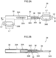
- the coupling members 28 each includes a tube shaped sleeve 30 that is open at both axial direction end portions, a tube shaped engagement member 32 provided so as to be slidable inside the sleeve 30, and a rod 34 engaged with the engagement member 32.
- a sliding member is configured by the engagement member 32 and the rod 34.
- a slit 30A (an example of a restricting section) is formed along the axial direction at an outer peripheral face of the sleeve 30 between the two axial direction end portions of the sleeve 30.
- An ellipsoidal shaped upper eyelet portion 30B is formed at the sleeve 30 at a position offset from the axial center of an axial direction upper end portion (left end portion in Fig. 2A ) of the sleeve 30.
- the upper eyelet portion 30B engages with the flange portion 22 of the upper attachment portions 16 of Fig. 1 .
- the upper eyelet portion 30B has a major diameter direction oriented in the same direction as the length direction of the coupling member 28 (namely, the axial direction of the sleeve 30), has a size that is slightly larger than the flange portion 22, and has a shape similar to that of the flange portion 22. Specifically, a major diameter length L1 of the upper eyelet portion 30B is longer than a long axis length R1 of the flange portion 22 illustrated in Fig. 3B .
- a minor diameter length L2 of the upper eyelet portion 30B is longer than a short axis length R2 of the flange portion 22 illustrated in Fig. 3B , and is shorter than the long axis length R1 of the flange portion 22.
- the upper eyelet portion 30B is attachable to or detachable from the flange portion 22 only when positioned such that the major diameter direction of the upper eyelet portion 30B is aligned with the long axis direction of the flange portion 22.
- a projection 32A is formed so as to project out from an outer peripheral face at an axial direction upper end portion (left end portion in Fig. 2A ) of the engagement member 32.
- the projection 32A has a diameter slightly smaller than a width of the slit 30A of the sleeve 30, and is inserted so as to be capable of sliding inside the slit 30A.
- a female threaded portion 32B is formed on an inner peripheral face of an axial direction lower end portion (the right end portion in Fig. 2B ) of the engagement member 32, and an opening 32C is formed at the outer peripheral face of the engagement member 32 at the axial direction lower end portion thereof.
- a male threaded portion 34A is formed at an axial direction upper end portion (left end portion in Fig. 2A ) of the rod 34, and the male threaded portion 34A is screwed into the female threaded portion 32B of the engagement member 32.
- a thread-free portion 36 is provided at a portion along the axial direction of the male threaded portion 34A, and a scale 36A is formed at the thread-free portion 36.
- An ellipsoidal shaped lower eyelet portion 34B is formed at an axial direction lower end portion (right end portion in Fig. 2A ) of the rod 34.
- the lower eyelet portion 34B engages with the flange portion 26 of the lower attachment portions 18 illustrated in Fig. 1 .
- the lower eyelet portion 34B is, for example, formed at the center axis of the rod 34, with a major diameter direction oriented in the same direction as the length direction of the coupling member 28 (namely, as the axial direction of the rod 34).
- the lower eyelet portion 34B similarly to the upper eyelet portion 30B, the lower eyelet portion 34B has a size that is slightly larger than the flange portion 26, and has a shape similar to that of the flange portion 26. Specifically, a major diameter length L1 of the lower eyelet portion 34B is longer than a long axis length R1 of the flange portion 26 illustrated in Fig. 3B .
- a minor diameter length L2 of the lower eyelet portion 34B is longer than a short axis length R2 of the flange portion 26 illustrated in Fig. 3B , and shorter than the long axis length R1 of the flange portion 26.
- the lower eyelet portion 34B is attachable to or detachable from the flange portion 26 only when positioned such that the major diameter direction of the lower eyelet portion 34B is aligned with the long axis direction of the flange portion 26.
- the coupling member 28 has a length that is adjustable in a continuous manner by axially rotating the rod 34 to adjust the amount of the male threaded portion 34A screwed into the female threaded portion 32B of the engagement member 32. Moreover, the coupling member 28 follows movement of the maxillary attachment 12 and the mandibular attachment 14 by the engagement member 32 sliding inside the sleeve 30.
- the engagement members 32 are restricted from sliding in both directions along the axial direction of the engagement members 32 by the projections 32A of the respective engagement members 32 abutting the two end portions (left and right end portions in Fig. 2A ) of the slits 30A of the sleeves 30.
- respective distances (distances between centers) between the upper attachment portions 16 and the lower attachment portions 18 are adjustable using the coupling members 28 over a range from about 18 mm to about 50 mm.
- the mouthpiece 10 is mounted to dentition in a state in which the maxillary attachment 12 and the mandibular attachment 14 are coupled together by the coupling members 28 by hooking the upper eyelet portions 30B onto the shaft portions 20 and hooking the lower eyelet portions 34B onto the shaft portions 24.
- the position of the mandibular attachment 14 is adjusted in this state by adjusting the amount of the male threaded portion 34A of Fig. 2A and Fig. 2B screwed into the female threaded portion 32B, such that the mandibular attachment 14 is positioned so that movement to the posterior side of the dentition does not occur with respect to the maxillary attachment 12.
- the amount by which the male threaded portion 34A is screwed in is confirmed by looking at the scale 36A formed at the thread-free portion 36 of the rod 34 through the opening 32C of the engagement member 32.
- the attachment angle M of the coupling member 28, namely, the angle of the major diameter of the upper eyelet portion 30B with respect to the opposing face 12B of the maxillary attachment 12, and the angle of the major diameter of the lower eyelet portion 34B with respect to the opposing face 14B of the mandibular attachment 14, are about 10 degrees.
- the angles of the long axes of the flange portions 22, 26 are not aligned with the angles of the major diameters of the upper eyelet portion 30B and the lower eyelet portion 34B.
- the flange portions 22, 26 are substantially unable to pass through the upper eyelet portion 30B and the lower eyelet portion 34B.
- the coupling members 28 are substantially irremovable from the upper attachment portions 16 and the lower attachment portions 18, maintaining the coupled state between the maxillary attachment 12 and the mandibular attachment 14.
- an attachment angle N of the coupling member 28, namely, an angle of the major diameter of the upper eyelet portion 30B to the opposing face 12B of the maxillary attachment 12, and an angle of the major diameter of the lower eyelet portion 34B to the opposing face 14B of the mandibular attachment 14, is from about 40 degrees to about 60 degrees.
- the angles of the long axes of the flange portions 22, 26 are not aligned with the angles of the major diameters of the upper eyelet portion 30B and the lower eyelet portion 34B.
- the flange portions 22, 26 are substantially unable to pass through the upper eyelet portion 30B and the lower eyelet portion 34B.
- the coupling members 28 are substantially irremovable from the upper attachment portions 16 and the lower attachment portions 18, maintaining the coupled state between the maxillary attachment 12 and the mandibular attachment 14.
- the coupling members 28 follow movement of the maxillary attachment 12 and the mandibular attachment 14 by the engagement members 32 sliding inside the sleeves 30.
- the projections 32A of the engagement members 32 move downward (toward the left in Fig. 3B ) from an upper end portion of the slit 30A of the sleeve 30 and abut a lower end portion (left end portion in Fig. 3B ) of the slit 30A.
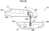
- the mouthpiece 10 is removed from the dentition. Then, as illustrated in Fig. 3C , the maxillary attachment 12 and the mandibular attachment 14 are separated from each other so as to lie in a substantially horizontal direction such that the attachment angles of the coupling members 28 are about 90 degrees.
- the angle of the major diameter of the upper eyelet portion 30B to the opposing face 12B of the maxillary attachment 12, and the angle of the major diameter of the lower eyelet portion 34B to the opposing face 14B of the mandibular attachment 14, also become about 90 degrees.
- the angles of the long axes of the flange portions 22, 26 and the angles of the major diameters of the upper eyelet portion 30B and the lower eyelet portion 34B are aligned with each other, and the flange portions 22, 26 are able to pass through the upper eyelet portion 30B and the lower eyelet portion 34B. This enables the coupling members 28 to be removed from the upper attachment portions 16 and the lower attachment portions 18.
- the amount by which the male threaded portion 34A is screwed into the female threaded portion 32B is adjusted by axially rotating the rod 34.
- the rods 34 are substantially non-axially-rotatable in a state in which the lower eyelet portion 34B is engaged with the flange portion 26.
- the rods 34 can be prevented from unintentionally rotating and changing the length of the coupling members 28 while the mouthpiece 10 is being worn on the dentition.
- the engagement members 32 are restricted from sliding in both directions along the axial direction of the engagement members 32 by the projections 32A of the engagement members 32, that are provided inside the respective sleeves 3, abutting the two end portions of the slits 30A formed between the two axial direction end portions of the sleeves 30.
- the projections 32A of the engagement members 32 move along the axial direction inside the slits 30A of the sleeves 30.
- the engagement members 32 can be suppressed from axially rotating with respect to the sleeves 30.
- the scales 36A formed at the thread-free portions 36 of the rods 34 are visible through the openings 32C of the engagement members 32. This enables the amount that the male threaded portions 34A have been screwed in to be confirmed while the male threaded portions 34A of the rods 34 have been screwed into the female threaded portions 32B of the engagement members 32.
- the ellipsoidal shaped flange portions 22, 26 are provided at the upper attachment portions 16 and the lower attachment portions 18, and the upper eyelet portions 30B and the lower eyelet portions 34B of the coupling members 28 are formed with ellipsoidal shapes that are slightly larger than those of the flange portions 22, 26 (namely, are formed in similar shapes thereto).
- angles of the long axes of the flange portions 22, 26 to the opposing faces 12B, 14B of the maxillary attachment 12 or the mandibular attachment 14 are about 90 degrees, i.e. lie outside the attachment angle range of the coupling members 28.
- the upper eyelet portion 30B of the lower eyelet portion 34B are easily attachable to or detachable from the flange portions 22, 26.
- the coupling members 28 can be easily switched between an attachable-detachable state and an attachment-detachment suppressed state by changing the attachment angle of the coupling members 28 with respect to the mouthpiece 10.
- maxillary attachment 12 and the mandibular attachment 14 can be more easily separated than configurations such as those in which the upper eyelet portion 30B and the lower eyelet portion 34B are bonded or screwed to the flange portions 22, 26. This thereby enables maintenance and replacement thereof.
- the upper eyelet portion 30B and the lower eyelet portion 34B being ellipsoidal shaped, when the mouthpiece 10 is being worn at the dentition, gaps are formed between the shaft portions 20 of the upper attachment portions 16 and the upper eyelet portion 30B, and between the shaft portions 24 of the lower attachment portions 18 and the lower eyelet portions 34B. This enables the coupling members 28 to more readily follow movements of the maxillary attachment 12 and the mandibular attachment 14 by the shaft portions 20, 24 sliding in these gaps.
- each of the coupling members 38 includes a tube shaped sleeve 40 that is open at both axial direction end portions, a tube shaped engagement member 42 provided so as to be slidable inside the sleeve 40, and a rod 44 engaged with the engagement member 42.
- a sliding member is configured by the engagement member 42 and the rod 44.
- a pair of slits 40A (an example of a restricting section) is formed at an outer peripheral face of each of the sleeves 40 between the two axial direction end portions thereof.
- the pair of slits 40A are each formed along the axial direction of the sleeves 40 at positions opposing each other.
- a circular pillar shaped pin 46 is attached to an axial direction upper end portion (left end portion in Fig. 4A ) of each of the engagement members 42 so as to pass through the engagement member 42 along a radial direction thereof.
- a diameter of the pins 46 is slightly smaller than the width of the slits 40A of the sleeves 40. Two end portions of the pins 46 project out from the outer peripheral faces of the engagement members 42, and are inserted inside the pairs of slits 40A so as to be capable of sliding along the slits 40A.
- the coupling members 38 have lengths that are variable by the engagement members 42 sliding inside the sleeves 40. When this occurs, sliding of the engagement members 42 is restricted in both directions along the axial direction of the engagement members 42 by the pins 46, attached to the engagement members 42, abutting the two end portions of the slits 40A of the sleeves 40 (the left and right end portions in Fig. 4A ).
- the coupling members 38 can be made more compact than configurations in which engagement members such as nuts are provided at outer sides of the sleeves 40, or the engagement members 42 and the rods 44 respectively abut at outer side end portions of the sleeves 40.
- the engagement members 42 can be suppressed from axially rotating with respect to the sleeves 40 when the engagement members 42 are sliding inside the sleeves 40.
- the coupling members 48 each includes a tube shaped sleeve 50 that is open at both axial direction end portions, a tube shaped engagement member 52 provided so as to be slidable inside the sleeve 50, and a rod 54 engaged with the engagement member 52.
- a sliding member is configured by the engagement member 52 and the rod 54.
- a pair of stoppers 56A, 56B (an example of a restricting section) is provided between the two axial direction end portions inside each of the sleeves 50.
- the stoppers 56A, 56B are each, for example, configured with a circular cylinder shape including a hollow portion, and are fixed to an inner peripheral face of the sleeve 50. Note that the shape of the stoppers 56A, 56B is not limited to being a circular cylinder shape, and may be any shape capable of abutting against abutting portions 52B, 52C of the engagement members 52, described later.
- An axial direction length of each of the engagement members 52 is shorter than a length between the stoppers 56A, 56B, namely, shorter than a length from a lower end portion of the stopper 56A at the upper end portion side (the left end portion side in Fig. 4B ) to an upper end portion of the stopper 56B at the lower end portion side (the right end portion side in Fig. 4B ).
- the engagement members 52 are each inserted inside the respective sleeve 50 between the stoppers 56A, 56B.
- the axial direction upper end portion of the engagement member 52 configures the abutting portion 52B that abuts the lower end portion of the stopper 56A
- the axial direction lower end portion of the engagement member 52 configures the abutting portion 52C that abuts the upper end portion of the stopper 56B.
- a lower eyelet portion 54B at the axial direction lower end portion (right end portion in Fig. 4B ) of each of the rods 54 is exposed from the sleeve 50.
- a male threaded portion 54A at an axial direction upper end portion (left end portion in Fig. 4B ) of the rod 54 is inserted through the hollow portion of the stopper 56B into the sleeve 50, and is screwed into a female threaded portion 52A of the engagement member 52.
- the coupling members 48 each has a length that is variable by the engagement members 52 sliding inside the sleeves 50 between the stoppers 56A, 56B. When this occurs, sliding of the engagement members 52 are restricted in both directions along the axial direction of the engagement members 52 by the abutting portions 52B, 52C of each of the engagement members 52 respectively abutting the stoppers 56A, 56B.
- sliding of the engagement members 52 inside the sleeves 50 are restricted in both directions along the axial direction of the engagement members 52 by the stoppers 56A, 56B that are provided between the two axial direction end portions provided inside the sleeves 50.
- This enables the coupling members 48 to be made more compact than configurations in which engagement members and stoppers are provided at outer sides of the sleeves 50.
- the coupling members 58 each includes a tube shaped sleeve 60 that is open at both axial direction end portions, a tube shaped engagement member 62 provided so as to be slidable inside the sleeve 60, and a rod 64 engaged with the engagement member 62.
- a sliding member is configured by the engagement member 62 and the rod 64.
- Narrow diameter portions 66A, 66B (an example of a restricting section) that have smaller internal diameters than internal diameters of other portions of each of the sleeves 60 are formed at inner peripheral faces of the sleeves 60 between the two axial direction end portions thereof.
- the narrow diameter portion 66A formed further to a lower end side (left end portion side in Fig. 5 ) from an axial direction upper end face of each of the sleeves 60 is formed by increasing a thickness of wall of the sleeve 60
- the narrow diameter portion 66B formed at an upper end side (right end portion side in Fig. 5 ) of the axial direction lower end face of the sleeve 60 is formed by crimping a lower end portion of the sleeve 60.
- a wider diameter portion 68 having an external diameter that is larger than an external diameter of other portions of the engagement member 62 is integrally formed at an axial direction upper end portion (left end portion in Fig. 5 ) of each of the engagement members 62.
- the wider diameter portions 68 of the engagement members 62 are slidable between the narrow diameter portions 66A, 66B of the sleeves 60.
- an insertion space 68A is formed at a central portion of an end face of the wider diameter portion 68 at the axial direction upper end portion side of each of the engagement members 62.
- the insertion space 68A is configured with grooves in a hexagonal shape that enable a tool such as a hex wrench to be inserted therein.
- a male threaded portion 64A formed at an axial direction upper end portion (left end portion in Fig. 5 ) of each of the rods 64 is screwed into a female threaded portion 62A formed at an inner peripheral face of each of the engagement members 62.
- an abutting portion 70 that abuts to an end face at the axial direction lower end portion side of the wider diameter portion 68 of the engagement member 62 is provided at an end face at the axial direction upper end portion side of each of the rods 64.
- the coupling members 58 have lengths that are variable by the engagement members 62 sliding inside the sleeves 60.
- sliding of the engagement members 62 are restricted in both directions along the axial direction of the engagement members 62 by the wider diameter portion 68 of each of the engagement members 62 respectively abutting a lower end portion (right end portion in Fig. 5 ) of the narrow diameter portions 66A of the sleeves 60, and abutting an upper end portion (left end portion in Fig. 5 ) of the narrow diameter portion 66B thereof.
- a hex wrench is inserted into the insertion space 68A of the wider diameter portion 68 of each of the engagement members 62 through the open axial direction upper end portion of the sleeve 60.
- the engagement members 62 are axially rotated by axially rotating the hex wrench, so as to adjust an amount by which the male threaded portion 64A of each of the rods 64 is screwed into the female threaded portion 62A of each of the engagement members 62.
- sliding of the engagement members 62 inside the sleeves 60 are restricted in both directions along the axial direction of the engagement members 62 by the narrow diameter portions 66A, 66B that are formed between the two axial direction end portions at the inner peripheral face of each of the sleeves 60.
- the axial direction position of the rods 64 can be adjusted with respect to the engagement members 62 by axial rotation of the engagement members 62, while not axially rotating the rods 64. This enables simple adjustment to be made to the length of the coupling members 58 in a state in which the lower eyelet portion 64B of each of the rods 64 is engaged with the flange portion 26 of Fig. 1 .
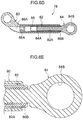
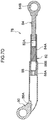
- the coupling members 78 each includes a tube shaped sleeve 80 that is open at both axial direction end portions, a tube shaped engagement member 82 provided so as to be slidable inside the sleeve 80, and a rod 84 engaged with the engagement member 82.
- a sliding member is configured by the engagement member 82 and the rod 84.
- an upper eyelet portion 80A having a perfect circle shape is formed at a position offset from an axial center of an axial direction upper end portion (lower end portion in Fig. 6A and Fig. 7A ) of the sleeve 80.
- the upper eyelet portion 80A engages with a flange portion at an upper attachment portion of a non-illustrated mouthpiece.
- narrow diameter portions 86A, 86B (an example of a restricting section) having internal diameters that are smaller than internal diameters of other portions of the sleeve 80 are formed at an inner peripheral face of each of the sleeves 80 between the two axial direction end portions thereof.
- the narrow diameter portions 86A formed at a lower end side of an axial direction upper end face of each of the sleeves 80 are formed by an increased thickness of wall of the sleeves 80.
- the narrow diameter portions 86B formed at an upper end side of an axial direction lower end face of each of the sleeves 80 are formed by crimping the axial direction lower end portions of the sleeves 80, as illustrated in Fig. 6E .
- a wider diameter portion 88 having an external diameter that is larger than an external diameter of other portions of the engagement member 82 is integrally formed at an axial direction upper end portion (lower end portion in Fig. 6D and Fig. 7D ) of each of the engagement members 82.
- the wider diameter portions 88 of the engagement members 82 are slidable between the narrow diameter portions 86A, 86B of the sleeves 80.
- an insertion space 88A is formed at a central portion of an end face of the wider diameter portion 88 at the axial direction upper end portion side of each of the engagement members 82.
- the insertion space 88A is configured with grooves in a hexagonal shape that enable a tool such as a hex wrench to be inserted therein.
- a male threaded portion 84A formed at an axial direction upper end portion (lower end portion in Fig. 6D and Fig. 7D ) of each of the rods 84 is screwed into a female threaded portion 82A formed at an inner peripheral face of the engagement members 82.
- a lower eyelet portion 84B having a perfect circle shape is formed at a center axis of the axial direction lower end portion (upper end portion in Fig. 6D and Fig. 7D ) of each of the rods 84.
- the lower eyelet portions 84B each engage with a flange portion at a lower attachment portion of a non-illustrated mouthpiece.
- the coupling members 78 have lengths that are variable by the engagement members 82 sliding inside the sleeves 80. When this occurs, sliding of the engagement members 82 are restricted in both directions along the axial direction of the engagement members 82 by the wider diameter portion 88 of each of the engagement members 82 respectively abutting the lower end portion (lower end portion side in Fig. 6D and Fig. 7D ) of the narrow diameter portion 86A of the sleeve 80, and abutting the upper end portion (the upper end portion side in Fig. 6D and Fig. 7D ) of the narrow diameter portion 86B of the sleeve 80 in each of the engagement members 82.
- a hex wrench is inserted into the insertion space 88A of the wider diameter portion 88 of each of the engagement members 82 through the open axial direction upper end portion of each of the sleeves 80.
- the amount that the male threaded portion 84A of each of the rods 84 is screwed into the female threaded portion 82A of each of the engagement members 82 is adjusted by axial rotation of the engagement members 82 by axially rotating the hex wrench.
- sliding of the engagement members 82 inside the sleeves 80 can be restricted in both directions along the axial direction of the engagement members 82 by the narrow diameter portions 86A, 86B formed between the two axial direction end portions at the inner peripheral face of each of the sleeves 80.
- the axial direction position of the rods 84 can be adjusted with respect to the engagement members 82 by axial rotation of the engagement members 82, while not axially rotating the rods 84. This enables simple adjustment to be made to the length of the coupling members 78 in a state in which the lower eyelet portions 84B of the rods 84 are engaged with the flange portions of the non-illustrated mouthpiece.
- the upper eyelet portions 30B and the lower eyelet portions 34B are attachable to or detachable from the flange portions 22, 26 of the upper attachment portions 16 and the lower attachment portions 18.
- the upper eyelet portion 30B and the lower eyelet portions 34B may be attached by bonding, screwing, or the like to the flange portions 22, 26 so as to be non-detachable therefrom.
- the upper attachment portions 16 and the lower attachment portions 18 are formed so as to respectively project out from the outer wall faces 12A, 14A of the maxillary attachment 12 and the mandibular attachment 14.
- the upper attachment portions 16 and the lower attachment portions 18 do not necessarily project from the outer wall faces 12A, 14A of the maxillary attachment 12 and the mandibular attachment 14, and may be provided at inner wall faces of the maxillary attachment 12 and the mandibular attachment 14.
- the maxillary attachment 12 and the mandibular attachment 14 are respectively mounted to maxillary and mandibular dentition.
- the maxillary attachment 12 and the mandibular attachment 14 may be mounted to maxillary and mandibular gums instead of the maxillary and mandibular dentition, or may be mounted to a separate member such as a dental brace that has been mounted to the dentition.
- the upper eyelet portions 30B are each formed at a position offset from the axial center of the respective sleeve 30, the upper eyelet portion 30B may be formed at the central axis of the sleeve 30.
- the lower eyelet portions 34B are each formed on the center axis of the respective rods 34, the lower eyelet portion 34B may be formed at a position offset from the axial center of the rod 34.
- a configuration may be adopted in which the amount by which the male threaded portion 34A is screwed in is confirmed by looking at the position of the upper end of the male threaded portion 34A through the opening 32C of the engagement member 32, without forming the scale 36A on each of the rods 34.
- the upper eyelet portions 30B, 40B, 50A and the lower eyelet portions 34B, 44B, 54B, 64B are respectively configured with ellipsoidal shapes, they may be configured with perfect circle shapes similarly to the upper eyelet portion 80A and the lower eyelet portion 84B of the fifth exemplary embodiment.
- the flange portions 22, 26 of the upper attachment portions 16 and the lower attachment portions 18 are configured with ellipsoidal shapes, they may be configured with perfect circle shapes. Moreover, the upper attachment portions 16 and the lower attachment portions 18 may be respectively attachable to or detachable from the maxillary attachment 12 and the mandibular attachment 14.
- part of nuts that include female threaded portions may be embedded in outer wall faces 12A, 14A of the maxillary attachment 12 and the mandibular attachment 14.
- An upper attachment portion and a lower attachment portion are then configured by bolts that include a shaft portion formed with a male threaded portion and a head portion (namely, flange portion) that has a perfect circle shape and is provided at the leading end of the shaft portion. This enables the upper attachment portion and the lower attachment portion to be attached to the maxillary attachment 12 and the mandibular attachment 14 by screwing the male threaded portions of these bolts into the female threaded portions of the nuts.
- the narrow diameter portions 66A are formed by increasing the thickness of the wall of the sleeves 60, and the narrow diameter portions 66B are formed by crimping the lower end portions of the sleeves 60.
- the methods of forming the narrow diameter portions 66A, 66B are not limited to the methods of the exemplary embodiments described above, and the narrow diameter portions 66A, 66B may be formed by the same method as each other.
- the wider diameter portions 68 are integrally formed at the engagement members 62, a configuration may be adopted in which wider diameter portions 68 that are separate members are joined to axial direction upper end portions of the engagement members 62.
- the restricting section is configured by the slits 30A, 40A, the stoppers 56A, 56B, or the narrow diameter portions 66A, 66B, 86A, 86B.
- the restricting section may be formed in any shape as long as the restricting section is formed between the two axial direction end portions of the sleeves 30, 40, 50, 60, 80, namely between one axial direction end face and another axial direction end face thereof, and the restricting section has a configuration in which sliding of the engagement member (sliding member) can be restricted in both directions along the axial direction of the engagement member.
- the male threaded portions 34A, 44A, 54A, 64A, 84A are formed at the rods 34, 44, 54, 64, 84, and the female threaded portions 32B, 42A, 52A, 62A, 82A are formed at the engagement members 32, 42, 52, 62, 82.
- female threaded portions may be formed at the rods 34, 44, 54, 64, 84 and male threaded portions may be formed at the engagement members 32, 42, 52, 62, 82.
- the sliding members are configured by separate members of the engagement members 32, 42, 52, 62, 82 and the rods 34, 44, 54, 64, 84 that screw together, such that the length of the sliding members is adjustable by adjusting the amount screwed in.
- the sliding members may be configured by a single member that is not adjustable in length.
- the materials for configuring the maxillary attachment 12 and the mandibular attachment 14, the upper attachment portions 16, the lower attachment portions 18, and the coupling members 28 are not limited to the examples of materials given in the exemplary embodiments described above.
- the upper attachment portions 16, the lower attachment portions 18, and the coupling members 28 are made of metal, they may be configured from a plastic from the perspectives of enabling application to patients with metal allergies, achieving a saving in weight while also retaining the strength of members, or reducing any feeling of discomfort inside the oral cavity.
- a mouthpiece includes a maxillary attachment that mounts to a maxilla, a mandibular attachment that mounts to a mandible, an upper attachment portion provided at the maxillary attachment, a lower attachment portion provided at the mandibular attachment, and a coupling member that is attached to the upper attachment portion and the lower attachment portion.
- the coupling member is suppressed from attaching to or detaching from the upper attachment portion and the lower attachment portion.
- the coupling member is attachable to or detachable from at least one of the upper attachment portion or the lower attachment portion.
- the second aspect enables the maxillary attachment and the mandibular attachment to be easily separated from each other due to the coupling member being attachable to or detachable from at least one of the upper attachment portion or the lower attachment portion at the attachment angle in the non-mounted state of the maxillary attachment and the mandibular attachment to the maxilla and the mandible.
- the mouthpiece according to an exemplary embodiment of the second aspect is configured similarly to the mouthpiece 10 of the first exemplary embodiment of the first aspect as illustrated in Fig. 1 to Fig. 3C , and so explanation will be omitted thereof.
- the flange portions 22, 26, the upper eyelet portions 30B, and the lower eyelet portions 34B are formed in similar ellipsoidal shapes to each other.
- the flange portions 22, 26, the upper eyelet portions 30B, and the lower eyelet portions 34B may be formed in any shape that suppress attaching or detaching of the coupling members 28 when the mouthpiece 10 is in a mounted state to the dentition, and that enables the coupling members 28 to be easily attachable or detachable in the non-mounted state of the mouthpiece 10.
- both the upper eyelet portions 30B and the lower eyelet portions 34B are attachable to or detachable from the flange portions 22, 26 when the mouthpiece 10 is in the non-mounted state to the dentition.
- only one of the upper eyelet portions 30B and the lower eyelet portions 34B needs to be attachable and detachable, and the other may be attached by bonding, screwing, or the like to the upper attachment portions 16 or the lower attachment portions 18 so as to be substantially non-detachable therefrom.
- the upper attachment portions 16 and the lower attachment portions 18 are formed so as to project out from the outer wall faces 12A, 14A of the maxillary attachment 12 and the mandibular attachment 14.
- the upper attachment portions 16 and the lower attachment portions 18 do not necessary project out from the outer wall faces 12A, 14A of the maxillary attachment 12 and the mandibular attachment 14, and may be provided at the inner wall faces of the maxillary attachment 12 and the mandibular attachment 14.
- the upper eyelet portions 30B are formed at positions offset from the axial center of the sleeves 30, the upper eyelet portions 30B may each be formed at the center axis of the respective sleeve 30.
- the directions of the major diameter of in the upper eyelet portions 30B and the lower eyelet portions 34B are oriented in the same direction as the length directions of the coupling members 28, a configuration may be adopted in which the major diameter directions are directions orthogonal to the length directions of the coupling members 28, or the like.
- the method of adjusting the length of the coupling members 28 is not limited to that of the exemplary embodiments described above. Furthermore, a configuration may be adopted in which the amount by which the male threaded portion 34A is screwed in is confirmed by looking at the position of the upper end of the male threaded portion 34A through the opening 32C of the engagement member 32, without forming the scale 36A on each of the rods 34.
Landscapes
- Health & Medical Sciences (AREA)
- Life Sciences & Earth Sciences (AREA)
- Animal Behavior & Ethology (AREA)
- General Health & Medical Sciences (AREA)
- Public Health (AREA)
- Veterinary Medicine (AREA)
- Oral & Maxillofacial Surgery (AREA)
- Dentistry (AREA)
- Epidemiology (AREA)
- Pulmonology (AREA)
- Engineering & Computer Science (AREA)
- Biomedical Technology (AREA)
- Heart & Thoracic Surgery (AREA)
- Otolaryngology (AREA)
- Nursing (AREA)
- Orthopedic Medicine & Surgery (AREA)
- Vascular Medicine (AREA)
- Emergency Medicine (AREA)
- Anesthesiology (AREA)
- Hematology (AREA)
- Orthopedics, Nursing, And Contraception (AREA)
- Dental Prosthetics (AREA)
Abstract
Description
- The present disclosure relates to a coupling member, and to a mouthpiece equipped with a coupling member.
- Hitherto, medical mouthpieces have been employed in the treatment of sleep apnea syndrome, temporomandibular joint disorders, and the like. An example of such a mouthpiece is a dental brace disclosed in Patent Document 1. This dental brace includes a connection member to connect a maxillary brace and a mandibular brace together, an extendible sleeve and an extendible rod that are attached to the connection member to adjust a relative position between the maxillary brace and the mandibular brace, and a nut to adjust the length of the extendible rod.
- Moreover, a dental brace including a maxillary brace that fits to maxillary dentition, a mandibular brace that fits to mandibular dentition, and a bite system that connects the maxillary brace and the mandibular brace together, is disclosed, for example in Patent Document 2.
-
- Patent Document 1: Specification of German Patent Application Publication No.
202012005525 - Patent Document 2: Specification of
US Patent Application Publication No. 2007/0224567 - In the dental brace disclosed in Patent Document 1, the nut to adjust the length of the extendible rod is employed as a stopper that abuts the connection member when the extendible rod is at its shortest length. However, the dental brace disclosed in Patent Document 1 is a bulky dental brace due to the nut, which is a separate member, being provided at an outer side.
- Moreover, in the dental brace disclosed in Patent Document 2, the bite system is fixed to the maxillary brace and the mandibular brace by fastenings. Thus to separate the maxillary brace and the mandibular brace from each other, there is a need to detach the fastenings by using a dedicated tool or the like to, for example, break the fastenings. Thus time and effort is required when there is a desire to replace the mandibular brace alone.
- An object of a first aspect of the present disclosure is accordingly to provide a compact coupling member, and a mouthpiece equipped with such a coupling member.
- Moreover, an object of a second aspect of the present disclosure is to provide a mouthpiece that enables easy separation of a maxillary attachment and a mandibular attachment that have been coupled together.
- The following exemplary embodiments <1> to <10> are examples of the first aspect of the present disclosure.
- The following exemplary embodiments <11> to <16> are examples of the second aspect of the present disclosure.
- <1> A coupling member includes a sliding member having one axial direction end portion that is configured to be coupled to a first attachment portion provided to a first attachment that is adapted to be mounted to one of a maxilla or a mandible, and a sleeve having one axial direction end portion that is configures to be coupled to a second attachment portion provided to a second attachment that is adapted to be mounted to the other of the maxilla and the mandible. The sliding member is inserted into the sleeve so as to be slidable, and a restricting section is formed at the sleeve between two axial direction end portions of the sleeve so as to restrict sliding of the sliding member in both directions along an axial direction of the sliding member.
According to the above configuration <1>, the coupling member can be made to follow movement of the first attachment and the second attachment by the sliding member sliding inside the sleeve. When this occurs, sliding of the sliding member of the coupling member is restricted in both directions along the axial direction of the sleeve by the restricting section that is formed between the two axial direction end portions of the sleeve.
Due to the sliding member being provided inside the sleeve in such cases, the coupling member can be made more compact than configurations in which engagement members such as nuts are provided at an outer portion of the sleeve. Note that "between two axial direction end portions" in the present disclosure indicates between one axial direction end face of the sleeve and another axial direction end face thereof, namely at an axial direction inner side of the two axial direction end faces of the sleeve. - <2> A coupling member recited in <1>, wherein the first attachment portion is formed projecting out from an outer wall face of the first attachment, the second attachment portion is formed projecting out from an outer wall face of the second attachment, and the sliding member is configured by a rod and a tube shaped engagement member. The rod has one axial direction end portion coupled to the first attachment portion and is formed with a screw portion at another axial direction end portion. The tube shaped engagement member has a screw receiving portion, that is formed at an inner peripheral face of one axial direction end portion of the engagement member, into which the screw portion of the rod is screwed.
According to the above configuration <2>, the length of the coupling member is adjusted by adjusting an amount by which the screw portion of the rod is screwed into the screw receiving portion of the engagement member, thereby enabling the relative position of the first attachment and the second attachment to be adjusted. Moreover, the coupling member can be made to follow movement of the first attachment and the second attachment by the engagement member sliding inside the sleeve. - <3> The coupling member recited in <2>, wherein the restricting section is configured by a slit formed at an outer peripheral face of the sleeve along the axial direction of the sleeve, a projection is formed at an outer peripheral face at another axial direction end portion of the engagement member, and the projection is inserted into the slit.
According to the above configuration <3>, sliding of the engagement member is restricted by the projection formed at the outer peripheral face of the engagement member abutting the two end portions of the slit formed at the outer peripheral face of the sleeve. Due to the projection of the engagement member moving inside the slit of the sleeve, the coupling member can be made to follow movement of the first attachment and the second attachment while also suppressing axial rotation of the engagement member with respect to the sleeve. - <4> The coupling member recited in <3>, wherein a pair of slits are formed at opposing positions at the outer peripheral face of the sleeve.
According to the above configuration <4>, the slits, into which projections of the engagement member are inserted into, are respectively formed at opposing positions at the outer peripheral face of the sleeve. Thus axial rotation of the engagement member with respect to the sleeve can be better suppressed. - <5> The coupling member recited in <2>, wherein the restricting section is configured by a pair of stoppers provided inside the sleeve, and the engagement member is inserted into the sleeve between the pair of stoppers.
According to the above configuration <5>, sliding of the engagement member is restricted in both directions in the axial direction of the engagement member by the stoppers due to the engagement member being inserted between the pair of stoppers provided inside the sleeve. Note that due to the stoppers being provided inside the sleeves, the coupling member can be made more compact than configurations in which stoppers are provided at an outer portion of the sleeve. - <6> The coupling member recited in <2>, wherein the restricting section is configured by narrow diameter portions formed at an inner peripheral face of the sleeve, and a wider diameter portion is formed at the engagement member so as to abut the narrow diameter portion.
According to the above configuration <6>, the narrow diameter portions are formed at the inner peripheral face of the sleeve, and the wider diameter portion is formed at the engagement member. Thus sliding of the engagement member is restricted in both directions in the axial direction of the engagement member by the wider diameter portion of the engagement member abutting the narrow diameter portions of the sleeve. Note that due to the wider diameter portion of the engagement member abutting the narrow diameter portions inside the sleeve, the coupling member can be made more compact than configurations in which the wider diameter portion of the engagement member abuts the sleeve at the outer side of the sleeve. - <7> The coupling member recited in any one of <2>, <5>, or <6>, wherein the engagement member is rotatable around an axis, and an amount that the screw portion of the rod is screwed into the screw receiving portion of the engagement member is adjustable by rotation about the axis of the engagement member.
According to the above configuration <7>, the amount by which the screw portion of the rod is screwed into the screw receiving portion of the engagement member can be adjusted by the rotation around the axis of the engagement member without rotating around an axis of the rod. This enables the length of the coupling member to be adjusted in a state in which one axial direction end portion of the rod is coupled to the first attachment portion. - <8> The coupling member recited in any one of <2>, or <5> to <7>, wherein one axial direction end portion of the sleeve is open, and an insertion space is formed at another axial direction end portion of the engagement member for inserting a tool therein.
According to the above configuration <8>, the engagement member can be rotated around the axis by inserting the tool into the insertion space of the engagement member through the one axial direction end portion of the sleeve and rotating the tool. Since the position of the rod with respect to the engagement member can be adjust without rotating the rod about the axis, the length of the coupling member can be adjusted in a state in which the rod is coupled to the first attachment portion of the first attachment. - <9> The coupling member recited in any one of <2> to <8>, wherein the screw portion of the rod is a male threaded portion having a scale formed thereon, the screw receiving portion of the engagement member is configured by a female threaded portion, and an opening is formed at an outer peripheral face of the engagement member at the one axial direction end portion of the engagement member.
According to the above configuration <9>, the length of the coupling member can be adjusted by adjusting the amount by which the male threaded portion of the rod is screwed into the female threaded portion of the engagement member. Since the scale is formed at the rod and the opening is formed at the outer peripheral face of the one axial direction end portion of the engagement member, the amount by which the male threaded portion is screwed into the female threaded portion can be visually confirmed by looking at the scale through the opening in the engagement member. - <10> A mouthpiece includes the coupling member of any one of <1> to <9>, a mandibular attachment serving as the first attachment, a maxillary attachment serving as the second attachment, the first attachment portion projecting from an outer wall face of the mandibular attachment, and the second attachment portion projecting from an outer wall face of the maxillary attachment.
According to the above configuration <10>, the mouthpiece includes the coupling member of any one of <1> to <9>, namely the coupling member in which sliding of the engagement member, that is inserted inside the sleeve, is restricted by the restricting section formed between the two axial direction end portions of the sleeve. This enables the mouthpiece to be made more compact than configurations which includes a coupling member in which an engagement member such as a nut is provided at an outer portion of the sleeve. - <11> A mouthpiece includes a maxillary attachment that is mounted to a maxilla, a mandibular attachment that is mounted to a mandible, an upper attachment portion provided at the maxillary attachment, a lower attachment portion provided at the mandibular attachment, and a coupling member. The coupling member is attached to the upper attachment portion and the lower attachment portion. At an attachment angle of the coupling member in a mounted state of the maxillary attachment and the mandibular attachment to the maxilla and the mandible, the coupling member is suppressed from attaching to or detaching from the upper attachment portion and the lower attachment portion. At an attachment angle of the coupling member in a non-mounted state of the maxillary attachment and the mandibular attachment to the maxilla and the mandible, the coupling member is attached to or detached from at least one of the upper attachment portion or the lower attachment portion.
According to the above configuration <11>, the coupling member is attachable to or detachable from at least one of the upper attachment portion or the lower attachment portion at an attachment angle of the coupling member in the non-mounted state of the maxillary attachment and the mandibular attachment to the maxilla and the mandible. Accordingly, the maxillary attachment and the mandibular attachment can be easily separated from each other.
However, attachment and detachment of the coupling member to the upper attachment portion and the lower attachment portion is suppressed at an attachment angle of the coupling member in the mounted state of the maxillary attachment and the mandibular attachment to the maxillary and the mandible. Accordingly, the coupled state can be maintained between the maxillary attachment and the mandibular attachment. - <12> The mouthpiece recited in <11>, wherein the upper attachment portion is formed projecting out from an outer wall face of the maxillary attachment, and the lower attachment portion is formed projecting out from an outer wall face of the mandibular attachment.
According to the above configuration <12>, the coupling member is easily attached to the upper attachment portion and the lower attachment portion due to the upper attachment portion and the lower attachment portion being formed respectively projecting out from the outer wall face of the maxillary attachment and the mandibular attachment. Moreover, when the coupling member is attached to the upper attachment portion and the lower attachment portion, movement of the tongue can be suppressed from being impeded by the coupling member better than in configurations in which the upper attachment portion and the lower attachment portion are provided at the inner wall faces or the like of the maxillary attachment and the mandibular attachment. - <13> The mouthpiece recited in <11> or <12>, wherein at least one of the upper attachment portion or the lower attachment portion includes a shaft portion provided with a flange portion having a long axis and a short axis and provided in a vicinity of a leading end of the shaft portion. The coupling member includes an eyelet portion that is engaged with the flange portion. The eyelet portion has a major diameter that is longer than a length of the long axis of the flange portion and has a minor diameter that is longer than a length of a short axis of the flange portion and shorter than the length of the long axis of the flange portion.
According to the above configuration <13>, the flange portion having the long axis and the short axis is provided at at least one of the upper attachment portion or the lower attachment portion. The major diameter of the eyelet portion of the coupling member is longer than the length of the long axis of the flange portion. The minor diameter of the coupling member is longer than the length of the short axis of the flange portion and shorter than the length of the long axis of the flange portion.
Thus the coupling member can be made attachable and detachable, or attaching and detaching of the coupling member can be suppressed, by changing an attachment angle of the coupling member with respect to the mouthpiece, namely by changing the attachment angle of the eyelet portion with respect to the flange portion. - <14> The mouthpiece recited in <13>, wherein the flange portion is able to pass through the eyelet portion when a long axis direction of the flange portion is aligned with a major diameter direction of the eyelet portion.
According to the above configuration <14>, the flange portion is able to pass through the eyelet portion when the long axis direction of the flange portion is aligned with the major diameter direction of the eyelet portion. Thus the eyelet portion of the coupling member can be removed from the flange portion of the upper attachment portion or the lower attachment portion by aligning the major diameter direction of the eyelet portion with the long axis direction of the flange portion in a non-mounted state of the maxillary attachment and the mandibular attachment to the maxillary and the mandible.
However, the eyelet portion is rendered substantially irremovable from the flange portion by ensuring the long axis direction of the flange portion and the major diameter direction of the eyelet portion are not aligned in a mounted state of the maxillary attachment and the mandibular attachment to the maxillary and the mandible. This enables the coupled state between the maxillary attachment and the mandibular attachment to be maintained. - <15> The mouthpiece recited in <13> or <14>, wherein the flange portion has a shape similar to a shape of the eyelet portion.
According to the above configuration <15>, due to the flange portion having a shape similar to a shape of the eyelet portion, the flange portion is able to pass through the eyelet portion by positioning the angle of the flange portion and the angle of the eyelet portion so as to be substantially aligned with each other. However, the flange portion is substantially unable to pass through the eyelet portion when the angle of the flange portion and the angle of the eyelet portion are not aligned with each other. - <16> The mouthpiece recited in <15> wherein the flange portion and the eyelet portion are formed with ellipsoidal shapes.
According to the above configuration <16>, the flange portion and the eyelet portion are formed with ellipsoidal shapes. Thus the coupling member can be made attachable and detachable, or attaching and detaching of the coupling member can be suppressed, without making the flange portion and the eyelet portion in a complicated shape. - <17> The mouthpiece recited in any one of <13> to <16>, wherein a major diameter direction of the eyelet portion is configured along a length direction of the coupling member, and an angle of the long axis of the flange portion with respect to an opposing face of the maxillary attachment, opposing the mandibular attachment, or with respect to an opposing face of the mandibular attachment, opposing the maxillary attachment, is outside of a range of from 10 degrees to 60 degrees.
According to the above configuration <17>, the attachment angle of the coupling member to the upper attachment portion or the lower attachment portion (the angle of the major diameter of the eyelet portion) is from about 10 degrees to about 60 degrees in a mounted state of the maxillary attachment and the mandibular attachment to the maxillary and the mandible. Thus, due to the angle of the long axis of the flange portion with respect to the opposing face of the mandibular attachment or the maxillary attachment is outside the range of from about 10 degrees to about 60 degrees, the eyelet portion can be prevented from coming off the flange portion in the mounted state of the maxillary attachment and the mandibular attachment to the maxillary and the mandible. - The first aspect enables provision of a compact coupling member, and a mouthpiece including a compact coupling member.
- The second aspect enables provision of a mouthpiece in which a maxillary attachment and a mandibular attachment that have been coupled together can be easily separate from each other.
-
-
Fig. 1 is a front view illustrating a mouthpiece according to a first exemplary embodiment of a first aspect. -
Fig. 2A is a plan view illustrating a coupling member of a mouthpiece according to the first exemplary embodiment of the first aspect. -
Fig. 2B is a cross-section taken on line B-B ofFig. 2A . -
Fig. 3A is a side view illustrating a mouthpiece according to the first exemplary embodiment of the first aspect in a closed state. -
Fig. 3B is a side view illustrating a mouthpiece according to the first exemplary embodiment of the first aspect in an open state. -
Fig. 3C is a side view illustrating a coupling member of a mouthpiece according to the first exemplary embodiment of the first aspect during detaching. -
Fig. 4A is a cross-section illustrating a coupling member of a mouthpiece according to a second exemplary embodiment of the first aspect. -
Fig. 4B is a cross-section illustrating a coupling member of a mouthpiece according to a third exemplary embodiment of the first aspect. -
Fig. 5 is a cross-section illustrating a coupling member of a mouthpiece according to a fourth exemplary embodiment of the first aspect. -
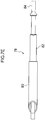
Fig. 6A is a front view illustrating a coupling member of a mouthpiece according to a fifth exemplary embodiment of the first aspect. -
Fig. 6B is a plan view of a coupling member of a mouthpiece according to the fifth exemplary embodiment of the first aspect. -
Fig. 6C is cross-section taken on line C-C inFig. 6A . -
Fig. 6D is a cross-section taken on line D-D inFig. 6B . -
Fig. 6E is an enlarged partial view illustrating an axial direction lower end portion of a sleeve ofFig. 6D . -
Fig. 6F is a side view illustrating a coupling member of a mouthpiece according to the fifth exemplary embodiment of the first aspect as viewed from the rod side. -
Fig. 6G is a side view illustrating a coupling member of a mouthpiece according to the fifth exemplary embodiment of the first aspect as viewed from the sleeve side. -
Fig. 6H is a bottom view illustrating a coupling member of a mouthpiece according to the fifth exemplary embodiment of the first aspect. -
Fig. 7A is a front view illustrating a coupling member of a mouthpiece according to the fifth exemplary embodiment of the first aspect in an extended state. -
Fig. 7B is a plan view illustrating a coupling member of a mouthpiece according to the fifth exemplary embodiment of the first aspect in an extended state. -
Fig. 7C is a cross-section taken on line E-E ofFig. 7A . -
Fig. 7D is a cross-section taken on line F-F ofFig. 7B . -
Fig. 7E is a bottom view illustrating a coupling member of a mouthpiece according to the fifth exemplary embodiment of the first aspect in an extended state. - In the present specification "a posterior side" indicates a back teeth (for example, tooth positions 4 to 8) side when the mouthpiece is being worn, namely, the palatal side. Moreover, "left and right sides" indicates the left and right sides when looking face-on to a center of dentition, namely tooth position 1.
- Explanation follows regarding examples of a first aspect and a second aspect of the present disclosure, with reference to the drawings. However, the present disclosure is not limited to the aspects illustrated in the drawings. Note that sizes of members in each of the drawings are only schematic, and relative size relationships between members are not limited thereto.
- A coupling member according to a first aspect of the present disclosure includes a sliding member having one axial direction end portion coupled to a first attachment portion, that is provided at a first attachment that is mounted to one of a maxilla or a mandible, and a sleeve having one axial direction end portion coupled to a second attachment portion, that is provided at a second attachment that is mounted to the other of the maxilla and the mandible. The sliding member is inserted into the sleeve so as to be capable of sliding, and a restricting section is formed at the sleeve between two axial direction end portions of the sleeve so as to restrict the sliding member from sliding in both directions along an axial direction of the sleeve.
- According to the first aspect, due to the sliding member of the coupling member being provided inside the sleeve, the coupling member can be made more compact than configurations in which an engagement member such as a nut is provided at an outer portion of the sleeve.
- Explanation follows regarding a mouthpiece according to a first exemplary embodiment of the first aspect, with reference to
Fig. 1 to Fig. 3C . - A
mouthpiece 10 of the present exemplary embodiment is, for example, a mouthpiece employed for sleep apnea syndrome that is utilized to reduce or prevent snoring and bruxism, and breathing interruptions or the like while sleeping. As illustrated inFig. 1 , themouthpiece 10 includes a maxillary attachment 12 (an example of a second attachment) that is mounted to maxillary dentition, and a mandibular attachment 14 (an example of a first attachment) that is mounted to mandibular dentition. - The
maxillary attachment 12 and themandibular attachment 14 are, for example, configured from an acrylic resin. However, they may be configured from a single hard material having a bending elastic modulus of from 2000 MPa to 3000 MPa, or from a combination of materials combining a soft material having a bending elastic modulus of from 10 MPa to 300 MPa, and a hard material having a bending elastic modulus of from 1000 MPa to 3000 MPa. - Note that the
maxillary attachment 12 and themandibular attachment 14 may be configured from a comparatively soft material having a tensile strength of 150 N or greater but less than 2000 N, or in particular from 150 N to 500 N. In such cases, themaxillary attachment 12 and themandibular attachment 14 have a high ability to conform to the teeth when themouthpiece 10 is being worn. - Note that tensile strength refers to a breaking strength when a stretch test is performed in the direction of the molars (namely, the posterior direction in the dentition) with a hole of 1.5 mm diameter opened at tooth position 6 of the maxillary attachment of a mouthpiece (of thickness 3 mm) manufactured using a Nissin standard model.
- Examples of materials having a tensile strength of 150 N or greater but less than 2000 N include olefin-based resins, polyester-based resins, urethane-based resins, polyamide-based resins, and acrylic-based rubber resins, and among these olefin-based resins are preferable.
- Olefin-based resins are polymers produced by polymerizing a single olefin, or copolymers produced by polymerizing an olefin with another monomer. Such olefins are preferably olefins with 2 to 6 carbons such as, for example, ethylene, propylene, butene, methylpentene, and hexane. Examples of other monomers include vinyl acetate.
- Preferable examples of olefin-based resins include polyethylene (PE), polyethylene-based resins, polypropylene (PP), polypropylene-based resins, ethylene-vinyl acetate copolymers (EVA). Polyethylene (PE), polyethylene-based resins, polypropylene (PP), and polypropylene-based resins are particularly preferable.
- Examples of polyester-based resins include condensation polymers of a polyvalent carboxylic acid (dicarboxylic acid) and a polyalcohol (diol), and a specific example thereof is polyethylene terephthalate (PET). Moreover, examples of urethane-based resins include condensation polymers of a compound including an isocyanate group and a compound including a hydroxide group, such as a thermoplastic polyurethane (TPU).
- Examples of polyamide-based resins include polymers of plural monomers bonded together by amide bonds, such as NYLON, para-amides, and meta-amides. Moreover, acrylic-based rubber resins are resins in which a main component is an acrylic-based rubber, and examples thereof include block-copolymers of methyl methacrylate and butyl acrylate.
- Commercially available materials may be employed as the material having a tensile strength of 150 N or greater but less than 2000 N, and, for example, F327 or the like manufactured by Prime Polymer Co., Ltd. may be employed as a polypropylene resin.
- Metal upper attachment portions 16 (examples of second attachment portions) are provided at an outer wall face 12A at left and right posterior sides of the maxillary attachment 12 (at tooth positions 6 to 7 in the present exemplary embodiment) as viewed from the center of dentition, so as to project out from the
outer wall face 12A. - Metal lower attachment portions 18 (examples of first attachment portions) are provided at an outer wall face 14A at left and right posterior sides of the mandibular attachment 14 (at tooth positions 3 to 4 in the present exemplary embodiment) as viewed from the center of dentition, so as to project out from the
outer wall face 14A. - The
upper attachment portions 16 each includes a circular bar shapedshaft portion 20 having one end fixed to theouter wall face 12A of themaxillary attachment 12, and aflange portion 22 provided at the other end (leading end) of theshaft portion 20. Note that theflange portion 22 has an ellipsoidal shape with a long axis and a short axis. Moreover, as illustrated inFig. 3B , an angle of the long axis of theflange portion 22 with respect to an opposingface 12B of themaxillary attachment 12 opposing themandibular attachment 14 is about 90 degrees. - Similarly, the
lower attachment portion 18 includes ashaft portion 24, and an ellipsoidal shapedflange portion 26 provided at a leading end of theshaft portion 24. Moreover, as illustrated inFig. 3B , an angle of the long axis of theflange portion 26 with respect to an opposingface 14B of themandibular attachment 14 opposing themaxillary attachment 12 is about 90 degrees. Note that the angles of the long axes of theflange portions - Moreover, the right
upper attachment portion 16 and the rightlower attachment portion 18, and the leftupper attachment portion 16 and the leftlower attachment portion 18, are coupled together by respectivemetal coupling members 28 so that thecoupling members 28 are rotatable about the axes of theupper attachment portions 16 and thelower attachment portions 18. Thecoupling members 28 couple themaxillary attachment 12 and themandibular attachment 14 together to enable opening and closing, and also position themandibular attachment 14 so that movement in a posterior side of the dentition does not occur with respect to themaxillary attachment 12. - In the
mouthpiece 10 of the present exemplary embodiment, theupper attachment portions 16 are disposed at a posterior side to (at a back teeth side of) thelower attachment portions 18 as viewed from the center of dentition. Namely, themouthpiece 10 is a push-type mouthpiece that, when being worn, pushes the mandibular attachment 14 (the mandible) forward using thecoupling members 28. - As illustrated in
Fig. 2A and Fig. 2B , thecoupling members 28 each includes a tube shapedsleeve 30 that is open at both axial direction end portions, a tube shapedengagement member 32 provided so as to be slidable inside thesleeve 30, and arod 34 engaged with theengagement member 32. Note that a sliding member is configured by theengagement member 32 and therod 34. - A
slit 30A (an example of a restricting section) is formed along the axial direction at an outer peripheral face of thesleeve 30 between the two axial direction end portions of thesleeve 30. An ellipsoidal shapedupper eyelet portion 30B is formed at thesleeve 30 at a position offset from the axial center of an axial direction upper end portion (left end portion inFig. 2A ) of thesleeve 30. Theupper eyelet portion 30B engages with theflange portion 22 of theupper attachment portions 16 ofFig. 1 . - The
upper eyelet portion 30B has a major diameter direction oriented in the same direction as the length direction of the coupling member 28 (namely, the axial direction of the sleeve 30), has a size that is slightly larger than theflange portion 22, and has a shape similar to that of theflange portion 22. Specifically, a major diameter length L1 of theupper eyelet portion 30B is longer than a long axis length R1 of theflange portion 22 illustrated inFig. 3B . - A minor diameter length L2 of the
upper eyelet portion 30B is longer than a short axis length R2 of theflange portion 22 illustrated inFig. 3B , and is shorter than the long axis length R1 of theflange portion 22. Thus theupper eyelet portion 30B is attachable to or detachable from theflange portion 22 only when positioned such that the major diameter direction of theupper eyelet portion 30B is aligned with the long axis direction of theflange portion 22. - A
projection 32A is formed so as to project out from an outer peripheral face at an axial direction upper end portion (left end portion inFig. 2A ) of theengagement member 32. Theprojection 32A has a diameter slightly smaller than a width of theslit 30A of thesleeve 30, and is inserted so as to be capable of sliding inside theslit 30A. Moreover, a female threadedportion 32B is formed on an inner peripheral face of an axial direction lower end portion (the right end portion inFig. 2B ) of theengagement member 32, and anopening 32C is formed at the outer peripheral face of theengagement member 32 at the axial direction lower end portion thereof. - A male threaded
portion 34A is formed at an axial direction upper end portion (left end portion inFig. 2A ) of therod 34, and the male threadedportion 34A is screwed into the female threadedportion 32B of theengagement member 32. A thread-free portion 36 is provided at a portion along the axial direction of the male threadedportion 34A, and ascale 36A is formed at the thread-free portion 36. - An ellipsoidal shaped
lower eyelet portion 34B is formed at an axial direction lower end portion (right end portion inFig. 2A ) of therod 34. Thelower eyelet portion 34B engages with theflange portion 26 of thelower attachment portions 18 illustrated inFig. 1 . Thelower eyelet portion 34B is, for example, formed at the center axis of therod 34, with a major diameter direction oriented in the same direction as the length direction of the coupling member 28 (namely, as the axial direction of the rod 34). - Moreover, similarly to the
upper eyelet portion 30B, thelower eyelet portion 34B has a size that is slightly larger than theflange portion 26, and has a shape similar to that of theflange portion 26. Specifically, a major diameter length L1 of thelower eyelet portion 34B is longer than a long axis length R1 of theflange portion 26 illustrated inFig. 3B . - Moreover, a minor diameter length L2 of the
lower eyelet portion 34B is longer than a short axis length R2 of theflange portion 26 illustrated inFig. 3B , and shorter than the long axis length R1 of theflange portion 26. Thus thelower eyelet portion 34B is attachable to or detachable from theflange portion 26 only when positioned such that the major diameter direction of thelower eyelet portion 34B is aligned with the long axis direction of theflange portion 26. - The
coupling member 28 has a length that is adjustable in a continuous manner by axially rotating therod 34 to adjust the amount of the male threadedportion 34A screwed into the female threadedportion 32B of theengagement member 32. Moreover, thecoupling member 28 follows movement of themaxillary attachment 12 and themandibular attachment 14 by theengagement member 32 sliding inside thesleeve 30. - When this occurs, the
engagement members 32 are restricted from sliding in both directions along the axial direction of theengagement members 32 by theprojections 32A of therespective engagement members 32 abutting the two end portions (left and right end portions inFig. 2A ) of theslits 30A of thesleeves 30. Note that respective distances (distances between centers) between theupper attachment portions 16 and thelower attachment portions 18 are adjustable using thecoupling members 28 over a range from about 18 mm to about 50 mm. - As illustrated in
Fig. 1 , themouthpiece 10 is mounted to dentition in a state in which themaxillary attachment 12 and themandibular attachment 14 are coupled together by thecoupling members 28 by hooking theupper eyelet portions 30B onto theshaft portions 20 and hooking thelower eyelet portions 34B onto theshaft portions 24. - The position of the
mandibular attachment 14 is adjusted in this state by adjusting the amount of the male threadedportion 34A ofFig. 2A and Fig. 2B screwed into the female threadedportion 32B, such that themandibular attachment 14 is positioned so that movement to the posterior side of the dentition does not occur with respect to themaxillary attachment 12. Note the amount by which the male threadedportion 34A is screwed in is confirmed by looking at thescale 36A formed at the thread-free portion 36 of therod 34 through theopening 32C of theengagement member 32. - In a closed mouth state, as illustrated in
Fig. 3A , posterior side movement (toward the right inFig. 3A ) of themandibular attachment 14 is restricted by theprojection 32A of theengagement member 32 abutting the upper end portion (the right end portion inFig. 3A ) of theslit 30A of thesleeve 30. - Moreover, in a closed mouth state, the attachment angle M of the
coupling member 28, namely, the angle of the major diameter of theupper eyelet portion 30B with respect to the opposingface 12B of themaxillary attachment 12, and the angle of the major diameter of thelower eyelet portion 34B with respect to the opposingface 14B of themandibular attachment 14, are about 10 degrees. - Due to the respective angles of the long axes of the
flange portions face 12B or the opposingface 14B being about 90 degrees in this state, the angles of the long axes of theflange portions upper eyelet portion 30B and thelower eyelet portion 34B. - Thus in a closed mouth state, the
flange portions upper eyelet portion 30B and thelower eyelet portion 34B. Namely, thecoupling members 28 are substantially irremovable from theupper attachment portions 16 and thelower attachment portions 18, maintaining the coupled state between themaxillary attachment 12 and themandibular attachment 14. - Similarly, in an open mouth state, as illustrated in
Fig. 3B , an attachment angle N of thecoupling member 28, namely, an angle of the major diameter of theupper eyelet portion 30B to the opposingface 12B of themaxillary attachment 12, and an angle of the major diameter of thelower eyelet portion 34B to the opposingface 14B of themandibular attachment 14, is from about 40 degrees to about 60 degrees. - Due to the respective angles of the long axes of the
flange portions face 12B or the opposingface 14B being about 90 degrees, the angles of the long axes of theflange portions upper eyelet portion 30B and thelower eyelet portion 34B. - Thus in an open mouth state, the
flange portions upper eyelet portion 30B and thelower eyelet portion 34B. Namely, thecoupling members 28 are substantially irremovable from theupper attachment portions 16 and thelower attachment portions 18, maintaining the coupled state between themaxillary attachment 12 and themandibular attachment 14. - Note that in an open mouth state, the
coupling members 28 follow movement of themaxillary attachment 12 and themandibular attachment 14 by theengagement members 32 sliding inside thesleeves 30. When this occurs, theprojections 32A of theengagement members 32 move downward (toward the left inFig. 3B ) from an upper end portion of theslit 30A of thesleeve 30 and abut a lower end portion (left end portion inFig. 3B ) of theslit 30A. - In order to attach or detach the
coupling members 28 to or from themaxillary attachment 12 and the mandibular attachment 14 (to or from theupper attachment portions 16 and the lower attachment portions 18), first themouthpiece 10 is removed from the dentition. Then, as illustrated inFig. 3C , themaxillary attachment 12 and themandibular attachment 14 are separated from each other so as to lie in a substantially horizontal direction such that the attachment angles of thecoupling members 28 are about 90 degrees. - When this is performed, the angle of the major diameter of the
upper eyelet portion 30B to the opposingface 12B of themaxillary attachment 12, and the angle of the major diameter of thelower eyelet portion 34B to the opposingface 14B of themandibular attachment 14, also become about 90 degrees. - Namely, the angles of the long axes of the
flange portions upper eyelet portion 30B and thelower eyelet portion 34B are aligned with each other, and theflange portions upper eyelet portion 30B and thelower eyelet portion 34B. This enables thecoupling members 28 to be removed from theupper attachment portions 16 and thelower attachment portions 18. - In the present exemplary embodiment, the amount by which the male threaded
portion 34A is screwed into the female threadedportion 32B is adjusted by axially rotating therod 34. Therods 34 are substantially non-axially-rotatable in a state in which thelower eyelet portion 34B is engaged with theflange portion 26. Thus therods 34 can be prevented from unintentionally rotating and changing the length of thecoupling members 28 while themouthpiece 10 is being worn on the dentition. - Moreover, in the present exemplary embodiment the
engagement members 32 are restricted from sliding in both directions along the axial direction of theengagement members 32 by theprojections 32A of theengagement members 32, that are provided inside the respective sleeves 3, abutting the two end portions of theslits 30A formed between the two axial direction end portions of thesleeves 30. - This enables the
coupling members 28 and themouthpiece 10 to be made more compact than configurations in which engagement members such as nuts are provided at outer portions of thesleeves 30, or theengagement members 32 and therods 34 abut at outside end portions of thesleeves 30. - Note that the
projections 32A of theengagement members 32 move along the axial direction inside theslits 30A of thesleeves 30. Thus when theengagement members 32 are sliding inside thesleeves 30, theengagement members 32 can be suppressed from axially rotating with respect to thesleeves 30. - Moreover, in the present exemplary embodiment, the
scales 36A formed at the thread-free portions 36 of therods 34 are visible through theopenings 32C of theengagement members 32. This enables the amount that the male threadedportions 34A have been screwed in to be confirmed while the male threadedportions 34A of therods 34 have been screwed into the female threadedportions 32B of theengagement members 32. - Moreover, in the present exemplary embodiment, the ellipsoidal shaped
flange portions upper attachment portions 16 and thelower attachment portions 18, and theupper eyelet portions 30B and thelower eyelet portions 34B of thecoupling members 28 are formed with ellipsoidal shapes that are slightly larger than those of theflange portions 22, 26 (namely, are formed in similar shapes thereto). - Furthermore, the angles of the long axes of the
flange portions maxillary attachment 12 or themandibular attachment 14 are about 90 degrees, i.e. lie outside the attachment angle range of thecoupling members 28. - This means that in a mounted state of the
mouthpiece 10 to dentition, theupper eyelet portions 30B and thelower eyelet portions 34B are suppressed such that theupper eyelet portions 30B and thelower eyelet portions 34B are substantially unable to be attached to or detached from theflange portions maxillary attachment 12 and themandibular attachment 14 to be maintained. - Moreover, in a non-mounted state of the
mouthpiece 10 to the dentition, theupper eyelet portion 30B of thelower eyelet portion 34B are easily attachable to or detachable from theflange portions coupling members 28 can be easily switched between an attachable-detachable state and an attachment-detachment suppressed state by changing the attachment angle of thecoupling members 28 with respect to themouthpiece 10. - Thus the
maxillary attachment 12 and themandibular attachment 14 can be more easily separated than configurations such as those in which theupper eyelet portion 30B and thelower eyelet portion 34B are bonded or screwed to theflange portions - Moreover, due to the
upper eyelet portion 30B and thelower eyelet portion 34B being ellipsoidal shaped, when themouthpiece 10 is being worn at the dentition, gaps are formed between theshaft portions 20 of theupper attachment portions 16 and theupper eyelet portion 30B, and between theshaft portions 24 of thelower attachment portions 18 and thelower eyelet portions 34B. This enables thecoupling members 28 to more readily follow movements of themaxillary attachment 12 and themandibular attachment 14 by theshaft portions - Next, explanation follows regarding
coupling members 38 of a mouthpiece according to a second exemplary embodiment of the first aspect, with reference toFig. 4A . Note that explanation will be omitted of configuration similar to that of thecoupling members 28 of the first exemplary embodiment. - As illustrated in
Fig. 4A , each of thecoupling members 38 includes a tube shapedsleeve 40 that is open at both axial direction end portions, a tube shapedengagement member 42 provided so as to be slidable inside thesleeve 40, and arod 44 engaged with theengagement member 42. Note that a sliding member is configured by theengagement member 42 and therod 44. - A pair of
slits 40A (an example of a restricting section) is formed at an outer peripheral face of each of thesleeves 40 between the two axial direction end portions thereof. The pair ofslits 40A are each formed along the axial direction of thesleeves 40 at positions opposing each other. A circular pillar shapedpin 46 is attached to an axial direction upper end portion (left end portion inFig. 4A ) of each of theengagement members 42 so as to pass through theengagement member 42 along a radial direction thereof. - A diameter of the
pins 46 is slightly smaller than the width of theslits 40A of thesleeves 40. Two end portions of thepins 46 project out from the outer peripheral faces of theengagement members 42, and are inserted inside the pairs ofslits 40A so as to be capable of sliding along theslits 40A. - The
coupling members 38 have lengths that are variable by theengagement members 42 sliding inside thesleeves 40. When this occurs, sliding of theengagement members 42 is restricted in both directions along the axial direction of theengagement members 42 by thepins 46, attached to theengagement members 42, abutting the two end portions of theslits 40A of the sleeves 40 (the left and right end portions inFig. 4A ). - In the present exemplary embodiment, sliding of the
engagement members 42 inside thesleeves 40 are restricted in both directions along the axial direction thereof by thepins 46, attached to theengagement members 42, abutting the two end portions of theslits 40A formed between the two axial direction end portions of thesleeves 40. Thus thecoupling members 38 can be made more compact than configurations in which engagement members such as nuts are provided at outer sides of thesleeves 40, or theengagement members 42 and therods 44 respectively abut at outer side end portions of thesleeves 40. - Moreover, due to the two end portions of the
pins 46 being respectively inserted into the pair ofslits 40A, provided at the outer peripheral face of each of thesleeves 40, theengagement members 42 can be suppressed from axially rotating with respect to thesleeves 40 when theengagement members 42 are sliding inside thesleeves 40. - Next, explanation follows regarding
coupling members 48 of a mouthpiece according to a third exemplary embodiment of the first aspect, with reference toFig. 4B . Note that explanation will be omitted of configuration similar to that of thecoupling members - As illustrated in
Fig. 4B , thecoupling members 48 each includes a tube shapedsleeve 50 that is open at both axial direction end portions, a tube shapedengagement member 52 provided so as to be slidable inside thesleeve 50, and arod 54 engaged with theengagement member 52. Note that a sliding member is configured by theengagement member 52 and therod 54. - A pair of
stoppers sleeves 50. Thestoppers sleeve 50. Note that the shape of thestoppers portions engagement members 52, described later. - An axial direction length of each of the
engagement members 52 is shorter than a length between thestoppers stopper 56A at the upper end portion side (the left end portion side inFig. 4B ) to an upper end portion of thestopper 56B at the lower end portion side (the right end portion side inFig. 4B ). Theengagement members 52 are each inserted inside therespective sleeve 50 between thestoppers - Note that the axial direction upper end portion of the
engagement member 52 configures the abuttingportion 52B that abuts the lower end portion of thestopper 56A, and the axial direction lower end portion of theengagement member 52 configures the abuttingportion 52C that abuts the upper end portion of thestopper 56B. - Moreover, a
lower eyelet portion 54B at the axial direction lower end portion (right end portion inFig. 4B ) of each of therods 54 is exposed from thesleeve 50. A male threadedportion 54A at an axial direction upper end portion (left end portion inFig. 4B ) of therod 54 is inserted through the hollow portion of thestopper 56B into thesleeve 50, and is screwed into a female threadedportion 52A of theengagement member 52. - The
coupling members 48 each has a length that is variable by theengagement members 52 sliding inside thesleeves 50 between thestoppers engagement members 52 are restricted in both directions along the axial direction of theengagement members 52 by the abuttingportions engagement members 52 respectively abutting thestoppers - According to the present exemplary embodiment, sliding of the
engagement members 52 inside thesleeves 50 are restricted in both directions along the axial direction of theengagement members 52 by thestoppers sleeves 50. This enables thecoupling members 48 to be made more compact than configurations in which engagement members and stoppers are provided at outer sides of thesleeves 50. - Explanation follows regarding
coupling members 58 of a mouthpiece according to a fourth exemplary embodiment of the first aspect, with reference toFig. 5 . Note that explanation will be omitted of configuration similar to that of thecoupling members - As illustrated in
Fig. 5 , thecoupling members 58 each includes a tube shapedsleeve 60 that is open at both axial direction end portions, a tube shapedengagement member 62 provided so as to be slidable inside thesleeve 60, and arod 64 engaged with theengagement member 62. Note that a sliding member is configured by theengagement member 62 and therod 64. -
Narrow diameter portions sleeves 60 are formed at inner peripheral faces of thesleeves 60 between the two axial direction end portions thereof. Note that thenarrow diameter portion 66A formed further to a lower end side (left end portion side inFig. 5 ) from an axial direction upper end face of each of thesleeves 60 is formed by increasing a thickness of wall of thesleeve 60, and thenarrow diameter portion 66B formed at an upper end side (right end portion side inFig. 5 ) of the axial direction lower end face of thesleeve 60 is formed by crimping a lower end portion of thesleeve 60. - A
wider diameter portion 68 having an external diameter that is larger than an external diameter of other portions of theengagement member 62 is integrally formed at an axial direction upper end portion (left end portion inFig. 5 ) of each of theengagement members 62. Thewider diameter portions 68 of theengagement members 62 are slidable between thenarrow diameter portions sleeves 60. - Moreover, an
insertion space 68A is formed at a central portion of an end face of thewider diameter portion 68 at the axial direction upper end portion side of each of theengagement members 62. Theinsertion space 68A is configured with grooves in a hexagonal shape that enable a tool such as a hex wrench to be inserted therein. - A male threaded
portion 64A formed at an axial direction upper end portion (left end portion inFig. 5 ) of each of therods 64 is screwed into a female threadedportion 62A formed at an inner peripheral face of each of theengagement members 62. Note that an abuttingportion 70 that abuts to an end face at the axial direction lower end portion side of thewider diameter portion 68 of theengagement member 62 is provided at an end face at the axial direction upper end portion side of each of therods 64. - The
coupling members 58 have lengths that are variable by theengagement members 62 sliding inside thesleeves 60. When theengagement members 62 are sliding, sliding of theengagement members 62 are restricted in both directions along the axial direction of theengagement members 62 by thewider diameter portion 68 of each of theengagement members 62 respectively abutting a lower end portion (right end portion inFig. 5 ) of thenarrow diameter portions 66A of thesleeves 60, and abutting an upper end portion (left end portion inFig. 5 ) of thenarrow diameter portion 66B thereof. - Moreover, in order to adjust the position of the
rods 64 with respect to theengagement members 62, a hex wrench is inserted into theinsertion space 68A of thewider diameter portion 68 of each of theengagement members 62 through the open axial direction upper end portion of thesleeve 60. Theengagement members 62 are axially rotated by axially rotating the hex wrench, so as to adjust an amount by which the male threadedportion 64A of each of therods 64 is screwed into the female threadedportion 62A of each of theengagement members 62. - In the present exemplary embodiment, sliding of the
engagement members 62 inside thesleeves 60 are restricted in both directions along the axial direction of theengagement members 62 by thenarrow diameter portions sleeves 60. - This enables the
coupling members 58 to be made more compact than configurations in which engagement members such as nuts are provided at an outer side of thesleeves 60, or theengagement members 62 androds 64 abut at the outer side end portions of thesleeves 60. - Moreover, in the present exemplary embodiment, the axial direction position of the
rods 64 can be adjusted with respect to theengagement members 62 by axial rotation of theengagement members 62, while not axially rotating therods 64. This enables simple adjustment to be made to the length of thecoupling members 58 in a state in which thelower eyelet portion 64B of each of therods 64 is engaged with theflange portion 26 ofFig. 1 . - Explanation follows regarding
coupling members 78 of a mouthpiece according to a fifth exemplary embodiment of the first aspect, with reference toFig. 6A to Fig. 7E . Note that explanation will be omitted of configuration similar to that of thecoupling members - As illustrated in
Fig. 6A to Fig. 7E , thecoupling members 78 each includes a tube shapedsleeve 80 that is open at both axial direction end portions, a tube shapedengagement member 82 provided so as to be slidable inside thesleeve 80, and arod 84 engaged with theengagement member 82. Note that a sliding member is configured by theengagement member 82 and therod 84. - As illustrated in
Fig. 6A andFig. 7A , anupper eyelet portion 80A having a perfect circle shape is formed at a position offset from an axial center of an axial direction upper end portion (lower end portion inFig. 6A andFig. 7A ) of thesleeve 80. Theupper eyelet portion 80A engages with a flange portion at an upper attachment portion of a non-illustrated mouthpiece. As illustrated inFig. 6D andFig. 7D ,narrow diameter portions sleeve 80 are formed at an inner peripheral face of each of thesleeves 80 between the two axial direction end portions thereof. - Note that the
narrow diameter portions 86A formed at a lower end side of an axial direction upper end face of each of the sleeves 80 (i.e. at the lower end portion side of thesleeves 80 inFig. 6D andFig. 7D ) are formed by an increased thickness of wall of thesleeves 80. Thenarrow diameter portions 86B formed at an upper end side of an axial direction lower end face of each of the sleeves 80 (i.e. at the upper end portion side of thesleeves 80 inFig. 6D andFig. 7D ) are formed by crimping the axial direction lower end portions of thesleeves 80, as illustrated inFig. 6E . - As illustrated in
Fig. 6D andFig. 7D , awider diameter portion 88 having an external diameter that is larger than an external diameter of other portions of theengagement member 82 is integrally formed at an axial direction upper end portion (lower end portion inFig. 6D andFig. 7D ) of each of theengagement members 82. Thewider diameter portions 88 of theengagement members 82 are slidable between thenarrow diameter portions sleeves 80. - Moreover, an
insertion space 88A is formed at a central portion of an end face of thewider diameter portion 88 at the axial direction upper end portion side of each of theengagement members 82. Theinsertion space 88A is configured with grooves in a hexagonal shape that enable a tool such as a hex wrench to be inserted therein. - A male threaded
portion 84A formed at an axial direction upper end portion (lower end portion inFig. 6D andFig. 7D ) of each of therods 84 is screwed into a female threadedportion 82A formed at an inner peripheral face of theengagement members 82. Moreover, alower eyelet portion 84B having a perfect circle shape is formed at a center axis of the axial direction lower end portion (upper end portion inFig. 6D andFig. 7D ) of each of therods 84. Thelower eyelet portions 84B each engage with a flange portion at a lower attachment portion of a non-illustrated mouthpiece. - The
coupling members 78 have lengths that are variable by theengagement members 82 sliding inside thesleeves 80. When this occurs, sliding of theengagement members 82 are restricted in both directions along the axial direction of theengagement members 82 by thewider diameter portion 88 of each of theengagement members 82 respectively abutting the lower end portion (lower end portion side inFig. 6D andFig. 7D ) of thenarrow diameter portion 86A of thesleeve 80, and abutting the upper end portion (the upper end portion side inFig. 6D andFig. 7D ) of thenarrow diameter portion 86B of thesleeve 80 in each of theengagement members 82. - Moreover, in order to adjust the position of the
rods 84 with respect to theengagement members 82, a hex wrench is inserted into theinsertion space 88A of thewider diameter portion 88 of each of theengagement members 82 through the open axial direction upper end portion of each of thesleeves 80. The amount that the male threadedportion 84A of each of therods 84 is screwed into the female threadedportion 82A of each of theengagement members 82 is adjusted by axial rotation of theengagement members 82 by axially rotating the hex wrench. - In the present exemplary embodiment, similarly to in the fourth exemplary embodiment, sliding of the
engagement members 82 inside thesleeves 80 can be restricted in both directions along the axial direction of theengagement members 82 by thenarrow diameter portions sleeves 80. - Moreover, the axial direction position of the
rods 84 can be adjusted with respect to theengagement members 82 by axial rotation of theengagement members 82, while not axially rotating therods 84. This enables simple adjustment to be made to the length of thecoupling members 78 in a state in which thelower eyelet portions 84B of therods 84 are engaged with the flange portions of the non-illustrated mouthpiece. - Note that the first aspect is not limited to the exemplary embodiments described above, and various other exemplary embodiments are possible within the scope of the present disclosure.
- For example, in the first exemplary embodiment, in a non-mounted state of the
mouthpiece 10 to the dentition, theupper eyelet portions 30B and thelower eyelet portions 34B are attachable to or detachable from theflange portions upper attachment portions 16 and thelower attachment portions 18. However, theupper eyelet portion 30B and thelower eyelet portions 34B may be attached by bonding, screwing, or the like to theflange portions - Moreover, in the first exemplary embodiment, the
upper attachment portions 16 and thelower attachment portions 18 are formed so as to respectively project out from the outer wall faces 12A, 14A of themaxillary attachment 12 and themandibular attachment 14. However, theupper attachment portions 16 and thelower attachment portions 18 do not necessarily project from the outer wall faces 12A, 14A of themaxillary attachment 12 and themandibular attachment 14, and may be provided at inner wall faces of themaxillary attachment 12 and themandibular attachment 14. - Moreover, in the first exemplary embodiment, the
maxillary attachment 12 and themandibular attachment 14 are respectively mounted to maxillary and mandibular dentition. However, themaxillary attachment 12 and themandibular attachment 14 may be mounted to maxillary and mandibular gums instead of the maxillary and mandibular dentition, or may be mounted to a separate member such as a dental brace that has been mounted to the dentition. - Moreover, although the
upper eyelet portions 30B are each formed at a position offset from the axial center of therespective sleeve 30, theupper eyelet portion 30B may be formed at the central axis of thesleeve 30. Similarly, although thelower eyelet portions 34B are each formed on the center axis of therespective rods 34, thelower eyelet portion 34B may be formed at a position offset from the axial center of therod 34. Furthermore, a configuration may be adopted in which the amount by which the male threadedportion 34A is screwed in is confirmed by looking at the position of the upper end of the male threadedportion 34A through theopening 32C of theengagement member 32, without forming thescale 36A on each of therods 34. - Moreover, although in the first to the fourth exemplary embodiments the
upper eyelet portions lower eyelet portions upper eyelet portion 80A and thelower eyelet portion 84B of the fifth exemplary embodiment. - Similarly, although in the first exemplary embodiment the
flange portions upper attachment portions 16 and thelower attachment portions 18 are configured with ellipsoidal shapes, they may be configured with perfect circle shapes. Moreover, theupper attachment portions 16 and thelower attachment portions 18 may be respectively attachable to or detachable from themaxillary attachment 12 and themandibular attachment 14. - Specifically, for example, part of nuts that include female threaded portions may be embedded in outer wall faces 12A, 14A of the
maxillary attachment 12 and themandibular attachment 14. An upper attachment portion and a lower attachment portion are then configured by bolts that include a shaft portion formed with a male threaded portion and a head portion (namely, flange portion) that has a perfect circle shape and is provided at the leading end of the shaft portion. This enables the upper attachment portion and the lower attachment portion to be attached to themaxillary attachment 12 and themandibular attachment 14 by screwing the male threaded portions of these bolts into the female threaded portions of the nuts. - Moreover, in the fourth exemplary embodiment, the
narrow diameter portions 66A are formed by increasing the thickness of the wall of thesleeves 60, and thenarrow diameter portions 66B are formed by crimping the lower end portions of thesleeves 60. However, the methods of forming thenarrow diameter portions narrow diameter portions wider diameter portions 68 are integrally formed at theengagement members 62, a configuration may be adopted in whichwider diameter portions 68 that are separate members are joined to axial direction upper end portions of theengagement members 62. - Moreover, in the exemplary embodiments described above, the restricting section is configured by the
slits stoppers narrow diameter portions sleeves - Moreover, in the first to the fifth exemplary embodiments, the male threaded
portions rods portions engagement members rods engagement members - Moreover, in the first to the fifth exemplary embodiments, the sliding members are configured by separate members of the
engagement members rods - Moreover, the materials for configuring the
maxillary attachment 12 and themandibular attachment 14, theupper attachment portions 16, thelower attachment portions 18, and thecoupling members 28 are not limited to the examples of materials given in the exemplary embodiments described above. For example, although theupper attachment portions 16, thelower attachment portions 18, and thecoupling members 28 are made of metal, they may be configured from a plastic from the perspectives of enabling application to patients with metal allergies, achieving a saving in weight while also retaining the strength of members, or reducing any feeling of discomfort inside the oral cavity. - A mouthpiece according to a second aspect of the present disclosure includes a maxillary attachment that mounts to a maxilla, a mandibular attachment that mounts to a mandible, an upper attachment portion provided at the maxillary attachment, a lower attachment portion provided at the mandibular attachment, and a coupling member that is attached to the upper attachment portion and the lower attachment portion. In the second aspect, at an attachment angle of the coupling member in a mounted state of the maxillary attachment and the mandibular attachment to the maxilla and the mandible, the coupling member is suppressed from attaching to or detaching from the upper attachment portion and the lower attachment portion. Further, is disposed at an attachment angle of the coupling member in a non-mounted state of the maxillary attachment and the mandibular attachment to the maxilla and the mandible, the coupling member is attachable to or detachable from at least one of the upper attachment portion or the lower attachment portion.
- The second aspect enables the maxillary attachment and the mandibular attachment to be easily separated from each other due to the coupling member being attachable to or detachable from at least one of the upper attachment portion or the lower attachment portion at the attachment angle in the non-mounted state of the maxillary attachment and the mandibular attachment to the maxilla and the mandible.
- The mouthpiece according to an exemplary embodiment of the second aspect is configured similarly to the
mouthpiece 10 of the first exemplary embodiment of the first aspect as illustrated inFig. 1 to Fig. 3C , and so explanation will be omitted thereof. - Note that the second aspect is not limited to the exemplary embodiments described above, and various other exemplary embodiments may be implemented within the scope of the present disclosure.
- For example, in the exemplary embodiments described above, as illustrated in
Fig. 1 to Fig. 3C , theflange portions upper eyelet portions 30B, and thelower eyelet portions 34B are formed in similar ellipsoidal shapes to each other. However, theflange portions upper eyelet portions 30B, and thelower eyelet portions 34B may be formed in any shape that suppress attaching or detaching of thecoupling members 28 when themouthpiece 10 is in a mounted state to the dentition, and that enables thecoupling members 28 to be easily attachable or detachable in the non-mounted state of themouthpiece 10. - Moreover, both the
upper eyelet portions 30B and thelower eyelet portions 34B are attachable to or detachable from theflange portions mouthpiece 10 is in the non-mounted state to the dentition. However, only one of theupper eyelet portions 30B and thelower eyelet portions 34B needs to be attachable and detachable, and the other may be attached by bonding, screwing, or the like to theupper attachment portions 16 or thelower attachment portions 18 so as to be substantially non-detachable therefrom. - Moreover, in the above exemplary embodiments the
upper attachment portions 16 and thelower attachment portions 18 are formed so as to project out from the outer wall faces 12A, 14A of themaxillary attachment 12 and themandibular attachment 14. However, theupper attachment portions 16 and thelower attachment portions 18 do not necessary project out from the outer wall faces 12A, 14A of themaxillary attachment 12 and themandibular attachment 14, and may be provided at the inner wall faces of themaxillary attachment 12 and themandibular attachment 14. - Moreover, although the
upper eyelet portions 30B are formed at positions offset from the axial center of thesleeves 30, theupper eyelet portions 30B may each be formed at the center axis of therespective sleeve 30. Furthermore, although the directions of the major diameter of in theupper eyelet portions 30B and thelower eyelet portions 34B are oriented in the same direction as the length directions of thecoupling members 28, a configuration may be adopted in which the major diameter directions are directions orthogonal to the length directions of thecoupling members 28, or the like. - Moreover, the method of adjusting the length of the
coupling members 28 is not limited to that of the exemplary embodiments described above. Furthermore, a configuration may be adopted in which the amount by which the male threadedportion 34A is screwed in is confirmed by looking at the position of the upper end of the male threadedportion 34A through theopening 32C of theengagement member 32, without forming thescale 36A on each of therods 34. - The entire disclosures of Japanese Patent Application Nos.
2016-141424 2016-141425 filed July 19, 2016 - All publications, patent applications and technical standards mentioned in the present specification are incorporated by reference in the present specification to the same extent as if each individual publication, patent application, or technical standard was specifically and individually indicated to be incorporated by reference.
Claims (17)
- A coupling member comprising:a sliding member having one axial direction end portion that is configured to be coupled to a first attachment portion provided at a first attachment that is adapted to be mounted to one of a maxilla or a mandible; anda sleeve having one axial direction end portion that is configured to be coupled to a second attachment portion provided at a second attachment that is adapted to be mounted to the other of the maxilla and the mandible, the sliding member being inserted into the sleeve so as to be slidable, and a restricting section being formed at the sleeve between two axial direction end portions of the sleeve so as to restrict sliding of the sliding member in both directions along an axial direction of the sliding member.
- The coupling member of claim 1, wherein:the first attachment portion is formed projecting out from an outer wall face of the first attachment;the second attachment portion is formed projecting out from an outer wall face of the second attachment; andthe sliding member is configured by a rod and a tube shaped engagement member, the rod having one axial direction end portion coupled to the first attachment portion and being formed with a screw portion at another axial direction end portion, and the tube shaped engagement member having a screw receiving portion, formed at an inner peripheral face of one axial direction end portion of the engagement member, into which the screw portion of the rod is screwed.
- The coupling member of claim 2, wherein the restricting section is configured by a slit formed at an outer peripheral face of the sleeve along the axial direction of the sleeve, a projection is formed at an outer peripheral face at another axial direction end portion of the engagement member, and the projection is inserted into the slit.
- The coupling member of claim 3, wherein a pair of slits are formed at opposing positions at the outer peripheral face of the sleeve.
- The coupling member of claim 2, wherein the restricting section is configured by a pair of stoppers provided inside the sleeve, and the engagement member is inserted between the pair of stoppers of the sleeve.
- The coupling member of claim 2, wherein the restricting section is configured by narrow diameter portions formed at an inner peripheral face of the sleeve, and a wider diameter portion is formed at the engagement member so as to abut the narrow diameter portions.
- The coupling member of any one of claims 2, 5, or 6, wherein the engagement member is rotatable about an axis, and an amount that the screw portion of the rod is screwed into the screw receiving portion of the engagement member is adjustable by rotation about the axis of the engagement member.
- The coupling member of any one of claims 2, or 5 to 7, wherein one axial direction end portion of the sleeve is open, and an insertion space is formed at another axial direction end portion of the engagement member for inserting a tool therein.
- The coupling member of any one of claims 2 to 8, wherein:the screw portion of the rod is a male threaded portion having a scale formed thereon;the screw receiving portion of the engagement member is a female threaded portion; andan opening is formed at an outer peripheral face of the engagement member at the one axial direction end portion of the engagement member.
- A mouthpiece comprising:the coupling member of any one of claims 1 to 9;a mandibular attachment serving as the first attachment;a maxillary attachment serving as the second attachment;the first attachment portion projecting from an outer wall face of the mandibular attachment; andthe second attachment portion projecting from an outer wall face of the maxillary attachment.
- A mouthpiece comprising:a maxillary attachment adapted to be mounted to a maxilla;a mandibular attachment adapted to be mounted to a mandible;an upper attachment portion provided at the maxillary attachment;a lower attachment portion provided at the mandibular attachment; anda coupling member, wherein:the coupling member is attached to the upper attachment portion and the lower attachment portion,at an attachment angle of the coupling member in a mounted state of the maxillary attachment and the mandibular attachment to the maxilla and the mandible, the coupling member is suppressed from attaching to or detaching from the upper attachment portion and the lower attachment portion, andat an attachment angle of the coupling member in a non-mounted state of the maxillary attachment and the mandibular attachment to the maxilla and the mandible, the coupling member is attachable to or detachable from at least one of the upper attachment portion or the lower attachment portion.
- The mouthpiece of claim 11, wherein the upper attachment portion is formed projecting out from an outer wall face of the maxillary attachment, and the lower attachment portion is formed projecting out from an outer wall face of the mandibular attachment.
- The mouthpiece of claim 11 or claim 12, wherein:at least one of the upper attachment portion or the lower attachment portion includes a shaft portion provided with a flange portion having a long axis and a short axis and provided in a vicinity of a leading end of the shaft portion; andthe coupling member includes an eyelet portion that is engaged with the flange portion, the eyelet portion having a major diameter that is longer than a length of the long axis of the flange portion and having a minor diameter that is longer than a length of the short axis of the flange portion and that is shorter than the length of the long axis of the flange portion.
- The mouthpiece of claim 13, wherein the flange portion is able to pass through the eyelet portion when a long axis direction of the flange portion is aligned with a major diameter direction of the eyelet portion.
- The mouthpiece of claim 13 or claim 14, wherein the flange portion is formed in a similar shape to a shape of the eyelet portion.
- The mouthpiece of claim 15, wherein the flange portion and the eyelet portion are formed with ellipsoidal shapes.
- The mouthpiece of any one of claims 13 to 16, wherein:a major diameter direction of the eyelet portion is configured along a length direction of the coupling member; andthe flange portion is configured such that an angle of the long axis of the flange portion with respect to an opposing face of the maxillary attachment, opposing the mandibular attachment, or with respect to an opposing face of the mandibular attachment, opposing the maxillary attachment, is outside of a range of from 10 degrees to 60 degrees.
Applications Claiming Priority (3)
| Application Number | Priority Date | Filing Date | Title |
|---|---|---|---|
| JP2016141424 | 2016-07-19 | ||
| JP2016141425 | 2016-07-19 | ||
| PCT/JP2017/022917 WO2018016258A1 (en) | 2016-07-19 | 2017-06-21 | Link member, and mouthpiece equipped with link member |
Publications (3)
| Publication Number | Publication Date |
|---|---|
| EP3488832A1 true EP3488832A1 (en) | 2019-05-29 |
| EP3488832A4 EP3488832A4 (en) | 2020-07-22 |
| EP3488832B1 EP3488832B1 (en) | 2022-08-03 |
Family
ID=60992142
Family Applications (1)
| Application Number | Title | Priority Date | Filing Date |
|---|---|---|---|
| EP17830778.1A Active EP3488832B1 (en) | 2016-07-19 | 2017-06-21 | Link member, and mouthpiece equipped with link member |
Country Status (5)
| Country | Link |
|---|---|
| US (1) | US11648088B2 (en) |
| EP (1) | EP3488832B1 (en) |
| JP (1) | JP6688889B2 (en) |
| CN (2) | CN109069286B (en) |
| WO (1) | WO2018016258A1 (en) |
Families Citing this family (18)
| Publication number | Priority date | Publication date | Assignee | Title |
|---|---|---|---|---|
| US12213907B2 (en) * | 2017-11-13 | 2025-02-04 | Achaemenid, Llc | Provisional oral sleep appliance |
| US12409060B2 (en) | 2017-11-13 | 2025-09-09 | Achaemenid, Llc | Strut assembly for oral appliance |
| CN111954507B (en) * | 2018-01-31 | 2023-03-24 | 奥丁睡眠有限责任公司 | Sleep apnea oral appliance with connector |
| CN108478297A (en) * | 2018-03-12 | 2018-09-04 | 哈尔滨医科大学 | Bouncing plate module activities appliance |
| US20210212801A1 (en) * | 2018-06-01 | 2021-07-15 | Mitsui Chemicals, Inc. | Dental coupling member and oral appliance |
| JP2019208735A (en) * | 2018-06-01 | 2019-12-12 | 三井化学株式会社 | Dental connection member, and mouth piece |
| AU2019278071B2 (en) | 2018-06-01 | 2022-03-24 | Mitsui Chemicals, Inc. | Dental coupling member and oral appliance |
| JPWO2021054133A1 (en) * | 2019-09-19 | 2021-03-25 | ||
| CN211750174U (en) * | 2019-11-04 | 2020-10-27 | 上海交通大学医学院附属第九人民医院 | Force application device for medical use in oral cavity and dental instrument for applying forward force to lower jaw |
| USD950066S1 (en) * | 2020-02-27 | 2022-04-26 | Mitsui Chemicals, Inc. | Hinge for oral sleep appliance |
| USD1042848S1 (en) | 2020-12-23 | 2024-09-17 | James R. Glidewell Dental Ceramics, Inc. | Dental appliance connecting arm |
| USD995781S1 (en) | 2021-05-28 | 2023-08-15 | Achaemenid, Llc | Strut assembly |
| USD980984S1 (en) | 2021-09-27 | 2023-03-14 | Yau Yau Cecilia Young | Orthodontic appliance |
| USD1059598S1 (en) | 2021-12-20 | 2025-01-28 | Achaemenid, Llc | Strut assembly |
| US20240016582A1 (en) * | 2022-07-14 | 2024-01-18 | World Class Technology Corporation | Orthodontic appliance for correcting misalignment of teeth |
| CN116158883A (en) * | 2023-04-06 | 2023-05-26 | 深圳市速航科技发展有限公司 | A cleaning component, cleaning device and dental equipment |
| AU2024376175A1 (en) * | 2023-11-09 | 2026-04-09 | World Class Technology Corporation | Orthodontic appliance for correcting misalignment of teeth |
| CN117898848B (en) * | 2024-03-20 | 2024-05-28 | 泉州医学高等专科学校 | Oral cavity appliance convenient to disassemble and assemble |
Family Cites Families (19)
| Publication number | Priority date | Publication date | Assignee | Title |
|---|---|---|---|---|
| NO891420D0 (en) * | 1989-04-06 | 1989-04-06 | Swadesh Kumar | ORTHODONTIC HANGING. |
| DE29619489U1 (en) * | 1996-11-09 | 1997-04-30 | Scheu-Dental, Inhaber Christian Scheu, 58642 Iserlohn | Modified autumn hinge |
| US6877982B2 (en) * | 1998-04-23 | 2005-04-12 | Michael O. Williams | Mandibular and maxillary arch expander having polygonal or ovoid rod and tube expanding elements |
| US6719557B1 (en) * | 1998-04-23 | 2004-04-13 | Michael O. Williams | Orthodontic appliance contraction connector |
| US6547560B1 (en) * | 2001-10-01 | 2003-04-15 | Juan F. Vazquez | Orthodontic bite jumping device with a telescoping limiting assembly |
| US20070224567A1 (en) | 2006-01-06 | 2007-09-27 | Robson Farrand C | Dental orthotic and methods of using the same |
| EP1976450B1 (en) * | 2006-01-11 | 2013-11-06 | Ormco Corporation | Orthodontic device for treating malocclusions |
| FR2933603B1 (en) | 2008-07-10 | 2012-03-16 | Gerard Vincent | ROD FOR DENTAL ARCADES AND ROD CONNECTING DEVICES |
| EP2269543B8 (en) | 2009-07-02 | 2013-02-13 | Somnowell Ltd. | Device for mandibular advancement |
| US20120070797A1 (en) * | 2010-09-22 | 2012-03-22 | Rmo, Inc. | Orthodontic Appliance and Method for Class II and Class III Malocclusion and Dental Asymmetric Correction |
| FR2974725B1 (en) * | 2011-05-03 | 2013-12-27 | Pul Concept | ORTHODONTIC APPARATUS WITH SLIDING RODS |
| US9237941B2 (en) * | 2011-12-22 | 2016-01-19 | Andrew Hayes | Orthodontic appliance and system |
| DE202012005525U1 (en) | 2012-06-06 | 2012-08-08 | Scheu-Dental Gmbh | Orthodontic device |
| TWI505843B (en) * | 2012-12-28 | 2015-11-01 | Univ Nat Cheng Kung | Oral snoring device |
| US20140224257A1 (en) * | 2013-02-12 | 2014-08-14 | Mark Abramson | Adjustable telescopic hinge system for relative positioning of the upper and lower jaw |
| US9144474B2 (en) * | 2013-03-11 | 2015-09-29 | American Orthodontics Corporation | Telescopic orthodontic appliance |
| CA2850988A1 (en) * | 2013-05-03 | 2014-11-03 | Resmed Sas | Improved mandibular repositioning device |
| US11877907B2 (en) * | 2014-03-13 | 2024-01-23 | Terry G. Dischinger | Method and apparatus for treating malocclusions and teeth alignment |
| DE202015000051U1 (en) * | 2015-01-12 | 2015-02-19 | Winfried Toussaint | Two-piece lower jaw protrusion splint |
-
2017
- 2017-06-21 CN CN201780022614.1A patent/CN109069286B/en not_active Expired - Fee Related
- 2017-06-21 CN CN202110310570.0A patent/CN113057748A/en active Pending
- 2017-06-21 JP JP2018528456A patent/JP6688889B2/en not_active Expired - Fee Related
- 2017-06-21 US US16/083,923 patent/US11648088B2/en active Active
- 2017-06-21 WO PCT/JP2017/022917 patent/WO2018016258A1/en not_active Ceased
- 2017-06-21 EP EP17830778.1A patent/EP3488832B1/en active Active
Also Published As
| Publication number | Publication date |
|---|---|
| CN109069286A (en) | 2018-12-21 |
| EP3488832B1 (en) | 2022-08-03 |
| CN113057748A (en) | 2021-07-02 |
| US11648088B2 (en) | 2023-05-16 |
| WO2018016258A1 (en) | 2018-01-25 |
| EP3488832A4 (en) | 2020-07-22 |
| US20190110866A1 (en) | 2019-04-18 |
| JP6688889B2 (en) | 2020-04-28 |
| CN109069286B (en) | 2021-07-20 |
| JPWO2018016258A1 (en) | 2018-10-11 |
Similar Documents
| Publication | Publication Date | Title |
|---|---|---|
| EP3488832B1 (en) | Link member, and mouthpiece equipped with link member | |
| JP6786619B2 (en) | Dental connecting members, mouthpieces and orthodontic appliances | |
| CN110087590B (en) | Tooth protector | |
| US20080176185A1 (en) | Jaw advancer connected to bone | |
| US9237941B2 (en) | Orthodontic appliance and system | |
| US9636192B2 (en) | Telescopic orthodontic appliance | |
| JP7211581B2 (en) | mouthpiece | |
| US20130052605A1 (en) | Buccal fixture for orthodontic use | |
| US20100190126A1 (en) | Nasal and maxillary growth enhancer | |
| WO2018126150A1 (en) | Polymer dental dam clamp and related assemblies and methods | |
| EP3811895B1 (en) | Dental coupling member and oral appliance | |
| US10258433B2 (en) | Device for intra-oral applications to reposition mandibular jaw | |
| US20150313751A1 (en) | Mandibular advancement device | |
| US20210212801A1 (en) | Dental coupling member and oral appliance | |
| US20100266976A1 (en) | Orthodontic functional appliance | |
| KR20200053901A (en) | System for clear aligner | |
| US20160074207A1 (en) | Oral appliance | |
| JP2020000829A (en) | Dental connecting member and mouth piece | |
| KR20170031739A (en) | An orthodontic ligature | |
| KR101501197B1 (en) | Self-ligating orthodontic bracket and bracket set | |
| CN210872263U (en) | Multifunctional bite-block | |
| CN107789080A (en) | A kind of anchorage base station for tooth implant | |
| US20200289309A1 (en) | Oral appliance | |
| JP2008161433A (en) | Release device of intermaxillary fixation |
Legal Events
| Date | Code | Title | Description |
|---|---|---|---|
| STAA | Information on the status of an ep patent application or granted ep patent |
Free format text: STATUS: THE INTERNATIONAL PUBLICATION HAS BEEN MADE |
|
| PUAI | Public reference made under article 153(3) epc to a published international application that has entered the european phase |
Free format text: ORIGINAL CODE: 0009012 |
|
| STAA | Information on the status of an ep patent application or granted ep patent |
Free format text: STATUS: REQUEST FOR EXAMINATION WAS MADE |
|
| 17P | Request for examination filed |
Effective date: 20181018 |
|
| AK | Designated contracting states |
Kind code of ref document: A1 Designated state(s): AL AT BE BG CH CY CZ DE DK EE ES FI FR GB GR HR HU IE IS IT LI LT LU LV MC MK MT NL NO PL PT RO RS SE SI SK SM TR |
|
| AX | Request for extension of the european patent |
Extension state: BA ME |
|
| DAV | Request for validation of the european patent (deleted) | ||
| DAX | Request for extension of the european patent (deleted) | ||
| RIC1 | Information provided on ipc code assigned before grant |
Ipc: A61C 7/36 20060101ALI20200206BHEP Ipc: A61M 16/06 20060101ALI20200206BHEP Ipc: A61F 5/56 20060101AFI20200206BHEP |
|
| A4 | Supplementary search report drawn up and despatched |
Effective date: 20200624 |
|
| RIC1 | Information provided on ipc code assigned before grant |
Ipc: A61C 7/36 20060101ALI20200618BHEP Ipc: A61M 16/06 20060101ALI20200618BHEP Ipc: A61F 5/56 20060101AFI20200618BHEP |
|
| STAA | Information on the status of an ep patent application or granted ep patent |
Free format text: STATUS: EXAMINATION IS IN PROGRESS |
|
| 17Q | First examination report despatched |
Effective date: 20210629 |
|
| GRAP | Despatch of communication of intention to grant a patent |
Free format text: ORIGINAL CODE: EPIDOSNIGR1 |
|
| STAA | Information on the status of an ep patent application or granted ep patent |
Free format text: STATUS: GRANT OF PATENT IS INTENDED |
|
| INTG | Intention to grant announced |
Effective date: 20220506 |
|
| GRAS | Grant fee paid |
Free format text: ORIGINAL CODE: EPIDOSNIGR3 |
|
| GRAA | (expected) grant |
Free format text: ORIGINAL CODE: 0009210 |
|
| STAA | Information on the status of an ep patent application or granted ep patent |
Free format text: STATUS: THE PATENT HAS BEEN GRANTED |
|
| AK | Designated contracting states |
Kind code of ref document: B1 Designated state(s): AL AT BE BG CH CY CZ DE DK EE ES FI FR GB GR HR HU IE IS IT LI LT LU LV MC MK MT NL NO PL PT RO RS SE SI SK SM TR |
|
| REG | Reference to a national code |
Ref country code: AT Ref legal event code: REF Ref document number: 1508161 Country of ref document: AT Kind code of ref document: T Effective date: 20220815 Ref country code: CH Ref legal event code: EP |
|
| REG | Reference to a national code |
Ref country code: DE Ref legal event code: R096 Ref document number: 602017060287 Country of ref document: DE |
|
| REG | Reference to a national code |
Ref country code: IE Ref legal event code: FG4D |
|
| REG | Reference to a national code |
Ref country code: LT Ref legal event code: MG9D |
|
| REG | Reference to a national code |
Ref country code: NL Ref legal event code: MP Effective date: 20220803 |
|
| REG | Reference to a national code |
Ref country code: DE Ref legal event code: R081 Ref document number: 602017060287 Country of ref document: DE Owner name: RESPIRE MEDICAL HOLDINGS LLC, NEW YORK, US Free format text: FORMER OWNER: MITSUI CHEMICALS, INC., TOKYO, JP Ref country code: DE Ref legal event code: R081 Ref document number: 602017060287 Country of ref document: DE Owner name: ORTHO SOLUTIONS, LC D/B/A DYNAFLEX, O FALLON, US Free format text: FORMER OWNER: MITSUI CHEMICALS, INC., TOKYO, JP |
|
| PG25 | Lapsed in a contracting state [announced via postgrant information from national office to epo] |
Ref country code: SE Free format text: LAPSE BECAUSE OF FAILURE TO SUBMIT A TRANSLATION OF THE DESCRIPTION OR TO PAY THE FEE WITHIN THE PRESCRIBED TIME-LIMIT Effective date: 20220803 Ref country code: RS Free format text: LAPSE BECAUSE OF FAILURE TO SUBMIT A TRANSLATION OF THE DESCRIPTION OR TO PAY THE FEE WITHIN THE PRESCRIBED TIME-LIMIT Effective date: 20220803 Ref country code: PT Free format text: LAPSE BECAUSE OF FAILURE TO SUBMIT A TRANSLATION OF THE DESCRIPTION OR TO PAY THE FEE WITHIN THE PRESCRIBED TIME-LIMIT Effective date: 20221205 Ref country code: NO Free format text: LAPSE BECAUSE OF FAILURE TO SUBMIT A TRANSLATION OF THE DESCRIPTION OR TO PAY THE FEE WITHIN THE PRESCRIBED TIME-LIMIT Effective date: 20221103 Ref country code: NL Free format text: LAPSE BECAUSE OF FAILURE TO SUBMIT A TRANSLATION OF THE DESCRIPTION OR TO PAY THE FEE WITHIN THE PRESCRIBED TIME-LIMIT Effective date: 20220803 Ref country code: LV Free format text: LAPSE BECAUSE OF FAILURE TO SUBMIT A TRANSLATION OF THE DESCRIPTION OR TO PAY THE FEE WITHIN THE PRESCRIBED TIME-LIMIT Effective date: 20220803 Ref country code: LT Free format text: LAPSE BECAUSE OF FAILURE TO SUBMIT A TRANSLATION OF THE DESCRIPTION OR TO PAY THE FEE WITHIN THE PRESCRIBED TIME-LIMIT Effective date: 20220803 Ref country code: FI Free format text: LAPSE BECAUSE OF FAILURE TO SUBMIT A TRANSLATION OF THE DESCRIPTION OR TO PAY THE FEE WITHIN THE PRESCRIBED TIME-LIMIT Effective date: 20220803 Ref country code: ES Free format text: LAPSE BECAUSE OF FAILURE TO SUBMIT A TRANSLATION OF THE DESCRIPTION OR TO PAY THE FEE WITHIN THE PRESCRIBED TIME-LIMIT Effective date: 20220803 |
|
| REG | Reference to a national code |
Ref country code: GB Ref legal event code: 732E Free format text: REGISTERED BETWEEN 20230112 AND 20230118 |
|
| REG | Reference to a national code |
Ref country code: AT Ref legal event code: MK05 Ref document number: 1508161 Country of ref document: AT Kind code of ref document: T Effective date: 20220803 |
|
| PG25 | Lapsed in a contracting state [announced via postgrant information from national office to epo] |
Ref country code: PL Free format text: LAPSE BECAUSE OF FAILURE TO SUBMIT A TRANSLATION OF THE DESCRIPTION OR TO PAY THE FEE WITHIN THE PRESCRIBED TIME-LIMIT Effective date: 20220803 Ref country code: IS Free format text: LAPSE BECAUSE OF FAILURE TO SUBMIT A TRANSLATION OF THE DESCRIPTION OR TO PAY THE FEE WITHIN THE PRESCRIBED TIME-LIMIT Effective date: 20221203 Ref country code: HR Free format text: LAPSE BECAUSE OF FAILURE TO SUBMIT A TRANSLATION OF THE DESCRIPTION OR TO PAY THE FEE WITHIN THE PRESCRIBED TIME-LIMIT Effective date: 20220803 Ref country code: GR Free format text: LAPSE BECAUSE OF FAILURE TO SUBMIT A TRANSLATION OF THE DESCRIPTION OR TO PAY THE FEE WITHIN THE PRESCRIBED TIME-LIMIT Effective date: 20221104 |
|
| PG25 | Lapsed in a contracting state [announced via postgrant information from national office to epo] |
Ref country code: SM Free format text: LAPSE BECAUSE OF FAILURE TO SUBMIT A TRANSLATION OF THE DESCRIPTION OR TO PAY THE FEE WITHIN THE PRESCRIBED TIME-LIMIT Effective date: 20220803 Ref country code: RO Free format text: LAPSE BECAUSE OF FAILURE TO SUBMIT A TRANSLATION OF THE DESCRIPTION OR TO PAY THE FEE WITHIN THE PRESCRIBED TIME-LIMIT Effective date: 20220803 Ref country code: DK Free format text: LAPSE BECAUSE OF FAILURE TO SUBMIT A TRANSLATION OF THE DESCRIPTION OR TO PAY THE FEE WITHIN THE PRESCRIBED TIME-LIMIT Effective date: 20220803 Ref country code: CZ Free format text: LAPSE BECAUSE OF FAILURE TO SUBMIT A TRANSLATION OF THE DESCRIPTION OR TO PAY THE FEE WITHIN THE PRESCRIBED TIME-LIMIT Effective date: 20220803 Ref country code: AT Free format text: LAPSE BECAUSE OF FAILURE TO SUBMIT A TRANSLATION OF THE DESCRIPTION OR TO PAY THE FEE WITHIN THE PRESCRIBED TIME-LIMIT Effective date: 20220803 |
|
| RAP4 | Party data changed (patent owner data changed or rights of a patent transferred) |
Owner name: MITSUI CHEMICALS, INC. |
|
| REG | Reference to a national code |
Ref country code: DE Ref legal event code: R097 Ref document number: 602017060287 Country of ref document: DE |
|
| PG25 | Lapsed in a contracting state [announced via postgrant information from national office to epo] |
Ref country code: SK Free format text: LAPSE BECAUSE OF FAILURE TO SUBMIT A TRANSLATION OF THE DESCRIPTION OR TO PAY THE FEE WITHIN THE PRESCRIBED TIME-LIMIT Effective date: 20220803 Ref country code: EE Free format text: LAPSE BECAUSE OF FAILURE TO SUBMIT A TRANSLATION OF THE DESCRIPTION OR TO PAY THE FEE WITHIN THE PRESCRIBED TIME-LIMIT Effective date: 20220803 |
|
| PLBE | No opposition filed within time limit |
Free format text: ORIGINAL CODE: 0009261 |
|
| STAA | Information on the status of an ep patent application or granted ep patent |
Free format text: STATUS: NO OPPOSITION FILED WITHIN TIME LIMIT |
|
| PG25 | Lapsed in a contracting state [announced via postgrant information from national office to epo] |
Ref country code: AL Free format text: LAPSE BECAUSE OF FAILURE TO SUBMIT A TRANSLATION OF THE DESCRIPTION OR TO PAY THE FEE WITHIN THE PRESCRIBED TIME-LIMIT Effective date: 20220803 |
|
| 26N | No opposition filed |
Effective date: 20230504 |
|
| PG25 | Lapsed in a contracting state [announced via postgrant information from national office to epo] |
Ref country code: SI Free format text: LAPSE BECAUSE OF FAILURE TO SUBMIT A TRANSLATION OF THE DESCRIPTION OR TO PAY THE FEE WITHIN THE PRESCRIBED TIME-LIMIT Effective date: 20220803 |
|
| REG | Reference to a national code |
Ref country code: GB Ref legal event code: 732E Free format text: REGISTERED BETWEEN 20231214 AND 20231220 |
|
| PG25 | Lapsed in a contracting state [announced via postgrant information from national office to epo] |
Ref country code: MC Free format text: LAPSE BECAUSE OF FAILURE TO SUBMIT A TRANSLATION OF THE DESCRIPTION OR TO PAY THE FEE WITHIN THE PRESCRIBED TIME-LIMIT Effective date: 20220803 |
|
| REG | Reference to a national code |
Ref country code: DE Ref legal event code: R082 Ref document number: 602017060287 Country of ref document: DE Representative=s name: DF-MP PATENTANWAELTE RECHTSANWAELTE PARTG MBB, DE Ref country code: DE Ref legal event code: R082 Ref document number: 602017060287 Country of ref document: DE Representative=s name: DF-MP DOERRIES FRANK-MOLNIA & POHLMAN PATENTAN, DE Ref country code: DE Ref legal event code: R081 Ref document number: 602017060287 Country of ref document: DE Owner name: ORTHO SOLUTIONS, LC D/B/A DYNAFLEX, O FALLON, US Free format text: FORMER OWNER: RESPIRE MEDICAL HOLDINGS LLC, NEW YORK, NY, US |
|
| PG25 | Lapsed in a contracting state [announced via postgrant information from national office to epo] |
Ref country code: MC Free format text: LAPSE BECAUSE OF FAILURE TO SUBMIT A TRANSLATION OF THE DESCRIPTION OR TO PAY THE FEE WITHIN THE PRESCRIBED TIME-LIMIT Effective date: 20220803 |
|
| REG | Reference to a national code |
Ref country code: CH Ref legal event code: PL |
|
| REG | Reference to a national code |
Ref country code: BE Ref legal event code: MM Effective date: 20230630 |
|
| PG25 | Lapsed in a contracting state [announced via postgrant information from national office to epo] |
Ref country code: LU Free format text: LAPSE BECAUSE OF NON-PAYMENT OF DUE FEES Effective date: 20230621 |
|
| REG | Reference to a national code |
Ref country code: IE Ref legal event code: MM4A |
|
| PG25 | Lapsed in a contracting state [announced via postgrant information from national office to epo] |
Ref country code: LU Free format text: LAPSE BECAUSE OF NON-PAYMENT OF DUE FEES Effective date: 20230621 |
|
| PG25 | Lapsed in a contracting state [announced via postgrant information from national office to epo] |
Ref country code: IE Free format text: LAPSE BECAUSE OF NON-PAYMENT OF DUE FEES Effective date: 20230621 |
|
| PG25 | Lapsed in a contracting state [announced via postgrant information from national office to epo] |
Ref country code: IE Free format text: LAPSE BECAUSE OF NON-PAYMENT OF DUE FEES Effective date: 20230621 Ref country code: CH Free format text: LAPSE BECAUSE OF NON-PAYMENT OF DUE FEES Effective date: 20230630 |
|
| PG25 | Lapsed in a contracting state [announced via postgrant information from national office to epo] |
Ref country code: IT Free format text: LAPSE BECAUSE OF FAILURE TO SUBMIT A TRANSLATION OF THE DESCRIPTION OR TO PAY THE FEE WITHIN THE PRESCRIBED TIME-LIMIT Effective date: 20220803 Ref country code: FR Free format text: LAPSE BECAUSE OF NON-PAYMENT OF DUE FEES Effective date: 20230630 Ref country code: BE Free format text: LAPSE BECAUSE OF NON-PAYMENT OF DUE FEES Effective date: 20230630 |
|
| PG25 | Lapsed in a contracting state [announced via postgrant information from national office to epo] |
Ref country code: BG Free format text: LAPSE BECAUSE OF FAILURE TO SUBMIT A TRANSLATION OF THE DESCRIPTION OR TO PAY THE FEE WITHIN THE PRESCRIBED TIME-LIMIT Effective date: 20220803 |
|
| PG25 | Lapsed in a contracting state [announced via postgrant information from national office to epo] |
Ref country code: BG Free format text: LAPSE BECAUSE OF FAILURE TO SUBMIT A TRANSLATION OF THE DESCRIPTION OR TO PAY THE FEE WITHIN THE PRESCRIBED TIME-LIMIT Effective date: 20220803 |
|
| PGFP | Annual fee paid to national office [announced via postgrant information from national office to epo] |
Ref country code: DE Payment date: 20250520 Year of fee payment: 9 |
|
| PGFP | Annual fee paid to national office [announced via postgrant information from national office to epo] |
Ref country code: GB Payment date: 20250520 Year of fee payment: 9 |
|
| PG25 | Lapsed in a contracting state [announced via postgrant information from national office to epo] |
Ref country code: CY Free format text: LAPSE BECAUSE OF FAILURE TO SUBMIT A TRANSLATION OF THE DESCRIPTION OR TO PAY THE FEE WITHIN THE PRESCRIBED TIME-LIMIT; INVALID AB INITIO Effective date: 20170621 |
|
| PG25 | Lapsed in a contracting state [announced via postgrant information from national office to epo] |
Ref country code: HU Free format text: LAPSE BECAUSE OF FAILURE TO SUBMIT A TRANSLATION OF THE DESCRIPTION OR TO PAY THE FEE WITHIN THE PRESCRIBED TIME-LIMIT; INVALID AB INITIO Effective date: 20170621 |
|
| PG25 | Lapsed in a contracting state [announced via postgrant information from national office to epo] |
Ref country code: TR Free format text: LAPSE BECAUSE OF FAILURE TO SUBMIT A TRANSLATION OF THE DESCRIPTION OR TO PAY THE FEE WITHIN THE PRESCRIBED TIME-LIMIT Effective date: 20220803 |