EP3488809B1 - Robotic surgical tools with latching mechanism - Google Patents
Robotic surgical tools with latching mechanism Download PDFInfo
- Publication number
- EP3488809B1 EP3488809B1 EP18208564.7A EP18208564A EP3488809B1 EP 3488809 B1 EP3488809 B1 EP 3488809B1 EP 18208564 A EP18208564 A EP 18208564A EP 3488809 B1 EP3488809 B1 EP 3488809B1
- Authority
- EP
- European Patent Office
- Prior art keywords
- retention tabs
- elongate shaft
- robotic surgical
- surgical tool
- tool
- Prior art date
- Legal status (The legal status is an assumption and is not a legal conclusion. Google has not performed a legal analysis and makes no representation as to the accuracy of the status listed.)
- Active
Links
- 230000007246 mechanism Effects 0.000 title claims description 80
- 230000014759 maintenance of location Effects 0.000 claims description 144
- 239000012636 effector Substances 0.000 claims description 63
- 238000000034 method Methods 0.000 claims description 22
- 230000006835 compression Effects 0.000 claims description 5
- 238000007906 compression Methods 0.000 claims description 5
- 230000007704 transition Effects 0.000 claims 1
- 230000008878 coupling Effects 0.000 description 27
- 238000010168 coupling process Methods 0.000 description 27
- 238000005859 coupling reaction Methods 0.000 description 27
- 210000000707 wrist Anatomy 0.000 description 27
- 230000033001 locomotion Effects 0.000 description 26
- 238000010586 diagram Methods 0.000 description 21
- 238000001356 surgical procedure Methods 0.000 description 18
- 230000004888 barrier function Effects 0.000 description 9
- 239000000463 material Substances 0.000 description 6
- 210000001015 abdomen Anatomy 0.000 description 5
- 230000013011 mating Effects 0.000 description 5
- 230000008901 benefit Effects 0.000 description 4
- 238000013459 approach Methods 0.000 description 2
- 230000000295 complement effect Effects 0.000 description 2
- 238000005520 cutting process Methods 0.000 description 2
- 230000000694 effects Effects 0.000 description 2
- 230000002262 irrigation Effects 0.000 description 2
- 238000003973 irrigation Methods 0.000 description 2
- 238000002357 laparoscopic surgery Methods 0.000 description 2
- 229920000642 polymer Polymers 0.000 description 2
- 238000012545 processing Methods 0.000 description 2
- 238000002432 robotic surgery Methods 0.000 description 2
- 238000003466 welding Methods 0.000 description 2
- AWYMFBJJKFTCFO-UHFFFAOYSA-N C(C1)C2C1CCC2 Chemical compound C(C1)C2C1CCC2 AWYMFBJJKFTCFO-UHFFFAOYSA-N 0.000 description 1
- 210000000683 abdominal cavity Anatomy 0.000 description 1
- 238000004026 adhesive bonding Methods 0.000 description 1
- 230000004075 alteration Effects 0.000 description 1
- 230000015572 biosynthetic process Effects 0.000 description 1
- 238000005219 brazing Methods 0.000 description 1
- 238000004891 communication Methods 0.000 description 1
- 238000010276 construction Methods 0.000 description 1
- 238000007796 conventional method Methods 0.000 description 1
- 230000003111 delayed effect Effects 0.000 description 1
- 230000001419 dependent effect Effects 0.000 description 1
- 238000013461 design Methods 0.000 description 1
- 238000011161 development Methods 0.000 description 1
- 238000010304 firing Methods 0.000 description 1
- 231100001261 hazardous Toxicity 0.000 description 1
- 238000003384 imaging method Methods 0.000 description 1
- 238000003780 insertion Methods 0.000 description 1
- 230000037431 insertion Effects 0.000 description 1
- 238000012830 laparoscopic surgical procedure Methods 0.000 description 1
- 238000004519 manufacturing process Methods 0.000 description 1
- 238000005259 measurement Methods 0.000 description 1
- 229910052751 metal Inorganic materials 0.000 description 1
- 239000002184 metal Substances 0.000 description 1
- 238000012986 modification Methods 0.000 description 1
- 230000004048 modification Effects 0.000 description 1
- 230000037361 pathway Effects 0.000 description 1
- 230000002980 postoperative effect Effects 0.000 description 1
- 238000011084 recovery Methods 0.000 description 1
- 239000000523 sample Substances 0.000 description 1
- 230000037390 scarring Effects 0.000 description 1
- 229920002379 silicone rubber Polymers 0.000 description 1
- 239000004945 silicone rubber Substances 0.000 description 1
- 238000005476 soldering Methods 0.000 description 1
- 229910001220 stainless steel Inorganic materials 0.000 description 1
- 239000010935 stainless steel Substances 0.000 description 1
- 239000013589 supplement Substances 0.000 description 1
- 230000001225 therapeutic effect Effects 0.000 description 1
- 238000013519 translation Methods 0.000 description 1
- WFKWXMTUELFFGS-UHFFFAOYSA-N tungsten Chemical compound [W] WFKWXMTUELFFGS-UHFFFAOYSA-N 0.000 description 1
- 229910052721 tungsten Inorganic materials 0.000 description 1
- 239000010937 tungsten Substances 0.000 description 1
Images


Classifications
-
- A—HUMAN NECESSITIES
- A61—MEDICAL OR VETERINARY SCIENCE; HYGIENE
- A61B—DIAGNOSIS; SURGERY; IDENTIFICATION
- A61B34/00—Computer-aided surgery; Manipulators or robots specially adapted for use in surgery
- A61B34/30—Surgical robots
-
- A—HUMAN NECESSITIES
- A61—MEDICAL OR VETERINARY SCIENCE; HYGIENE
- A61B—DIAGNOSIS; SURGERY; IDENTIFICATION
- A61B17/00—Surgical instruments, devices or methods, e.g. tourniquets
- A61B17/28—Surgical forceps
- A61B17/29—Forceps for use in minimally invasive surgery
-
- A—HUMAN NECESSITIES
- A61—MEDICAL OR VETERINARY SCIENCE; HYGIENE
- A61B—DIAGNOSIS; SURGERY; IDENTIFICATION
- A61B17/00—Surgical instruments, devices or methods, e.g. tourniquets
- A61B2017/00477—Coupling
-
- A—HUMAN NECESSITIES
- A61—MEDICAL OR VETERINARY SCIENCE; HYGIENE
- A61B—DIAGNOSIS; SURGERY; IDENTIFICATION
- A61B34/00—Computer-aided surgery; Manipulators or robots specially adapted for use in surgery
- A61B34/30—Surgical robots
- A61B2034/302—Surgical robots specifically adapted for manipulations within body cavities, e.g. within abdominal or thoracic cavities
-
- A—HUMAN NECESSITIES
- A61—MEDICAL OR VETERINARY SCIENCE; HYGIENE
- A61B—DIAGNOSIS; SURGERY; IDENTIFICATION
- A61B34/00—Computer-aided surgery; Manipulators or robots specially adapted for use in surgery
- A61B34/30—Surgical robots
- A61B2034/305—Details of wrist mechanisms at distal ends of robotic arms
Landscapes
- Health & Medical Sciences (AREA)
- Surgery (AREA)
- Life Sciences & Earth Sciences (AREA)
- Engineering & Computer Science (AREA)
- Medical Informatics (AREA)
- Biomedical Technology (AREA)
- Heart & Thoracic Surgery (AREA)
- Nuclear Medicine, Radiotherapy & Molecular Imaging (AREA)
- Molecular Biology (AREA)
- Animal Behavior & Ethology (AREA)
- General Health & Medical Sciences (AREA)
- Public Health (AREA)
- Veterinary Medicine (AREA)
- Robotics (AREA)
- Ophthalmology & Optometry (AREA)
- Surgical Instruments (AREA)
Description
-
US 6,451,027 B1 describes an endoscope locating formation that is typically releasably secured on an endoscope and includes diametrically opposed latches. - Minimally invasive surgical (MIS) tools and procedures can often be preferred over traditional open surgical techniques due to their ability to decrease post-operative recovery time and to leave minimal scarring. Laparoscopic surgery is one type of MIS procedure in which one or more small incisions are formed in the abdomen of a patient and a trocar is inserted through each incision to provide a surgical access pathway for an appropriate surgical tool. Trocars can additionally provide an internal seal assembly used for maintaining insufflation of the abdomen during a surgical procedure.
- A variety of MIS tools can be inserted into the abdominal cavity of a patient via a trocar and maneuvered from outside the abdomen. Laparoscopic surgical tools, for example, are often similar to those used in traditional surgical procedures, with the exception that laparoscopic surgical tools possess an elongate shaft extending from an end effector to a location outside the abdomen. The end effector is the surgically functional part of the surgical tool. The elongate shaft protrudes externally through a trocar when the surgical tool is inserted in the abdomen of a patient, and an external portion of the surgical tool provides a means for manipulating and communicating with the end effector. Once inserted in a patient's body, the end effector can engage and/or treat tissue in a number of ways to achieve a desired diagnostic or therapeutic effect. Illustrative end effectors of laparoscopic and similar surgical tools include, but are not limited to, scissors, graspers, needle drivers, clamps, staplers, cauterizers, suction tools, irrigation tools, clip appliers, and the like.
- Robotic surgery represents a specialized class of laparoscopic surgical procedures. Instead of directly engaging a surgical tool, as in traditional laparoscopic surgery, a surgeon instead manipulates and engages the surgical tool using an electronic interface communicatively coupled to a robotic manipulator. Manipulation and engagement of a surgical tool under robotic control can allow much more precise surgical procedures to be performed in many instances. In some instances, a surgeon need not even be in the operating room with the patient. Advantageously, robotic surgical systems can allow intuitive hand movements to be realized by maintaining a natural eye-hand axis. In addition, robotic surgical systems can incorporate a "wrist" coupling the end effector to the elongate shaft to provide natural, hand-like articulation during a robotic surgical procedure. The wrist can also facilitate an expanded and more complex range of motion than is possible with a human wrist, which can allow highly elaborate and precise surgical procedures to be performed.
- In robotic surgery procedures and systems, a surgical tool is removably coupled via a mounting fixture (also referred to as a tool driver) to an arm of a robotic manipulator, and the surgical tool is then manipulated and engaged via the robotic manipulator under a surgeon's direction. Mounting the surgical tool to the robotic manipulator may take place using mating techniques such as, for example, snap or press fitting, slidable coupling, complementary part coupling, mechanical attachment, magnetic coupling and the like. In many instances, such mating techniques can be sufficient to hold a surgical tool in place throughout a surgical procedure.
- Although these mating techniques are usually sufficient to maintain coupling to the mounting fixture, elevated tensile loads within the robotic surgical tool during use can result in inadvertent and unplanned tool decoupling from the robotic manipulator. Additional factors that may lead to unplanned tool decoupling include, for example, internal loading of the robotic surgical tool or external loading arising from biasing against a patient or another surgical tool. Rotational loading and impact loading may also occur in some instances and likewise promote unplanned tool decoupling. Unplanned tool decoupling can be hazardous to both a patient and operating room personnel, as well as potentially damaging the robotic surgical tool and/or the robotic manipulator.
- The following figures are included to illustrate certain aspects of the present disclosure, and should not be viewed as exclusive embodiments. The subject matter disclosed is capable of considerable modifications, alterations, combinations, and equivalents in form and function, without departing from the scope of this disclosure.
-
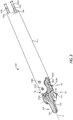
FIG. 1 shows a diagram of an illustrative robotic surgical tool that may incorporate certain principles of the present disclosure. -
FIG. 2 shows a diagram illustrating the degrees of freedom through which a wrist of a robotic surgical tool may articulate. -
FIGS. 3-5 show various views of an illustrative robotic surgical tool containing an end effector. -
FIG. 6 shows a diagram of an illustrative manner of coupling between a robotic surgical tool and a robotic manipulator. -
FIGS. 7 and 8 show diagrams illustrating more details of the releasable coupling between a robotic surgical tool and a mounting fixture of a robotic manipulator, which may incorporate certain principles of the present disclosure. -
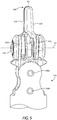
FIG. 9 shows a diagram of a first latching mechanism configuration of the present disclosure in engagement with a mounting fixture of a robotic manipulator. -
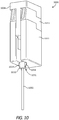
FIG. 10 shows a diagram of a second latching mechanism configuration of the present disclosure in engagement with a mounting fixture of a robotic manipulator. -
FIGS. 11 and 12 show diagrams illustrating further details of a first latching mechanism configuration, in which retention tabs are in a deployed state and a non-deployed state, respectively. -
FIGS. 13-16 show diagrams illustrating how retention tabs of a first latching mechanism configuration are deployed upon passage through a mounting fixture, optionally with cable engagement when the retention tabs are in a deployed state or a non-deployed state. -
FIGS. 17 and 18 show diagrams illustrating a first latching mechanism configuration in which a biasing force is supplied by spring-loaded cams. -
FIGS. 19 and 20 show diagrams illustrating further details of a second latching mechanism configuration, in which retention tabs are in a deployed state and a non-deployed state, respectively. -
FIGS. 21 and 22 show diagrams illustrating how a removal tool with a chamfered surface may facilitate retraction of retention tabs in a latching mechanism. - The present invention is defined in independent claims 1, 2, 14 and 15, and further embodiments are defined in the dependent claims. The present disclosure generally describes robotic surgical tools and, more specifically, systems and methods for securing a robotic surgical tool to a mounting fixture of a robotic manipulator.
- As discussed above, robotic surgical tools can be subject to extreme forces, including high tensile loads, under certain circumstances during a surgical procedure. In some instances, such forces can be significant enough to promote unwanted tool decoupling from the mounting fixture of a robotic manipulator.
- The present disclosure describes systems and methods that employ a latching mechanism as a secondary fastener for more robustly coupling a robotic surgical tool to the mounting fixture of a robotic manipulator. The latching mechanisms disclosed herein aid in avoiding inadvertent tool decoupling during a surgical procedure. The latching mechanisms can be deployed automatically under the influence of a biasing force once the robotic surgical tool has been coupled to the mounting fixture.
- At least some configurations of the latching mechanisms disclosed herein can perform an additional function of engaging cables or similar elongate members that are used for operating the end effector of the robotic surgical tool. In particularly advantageous configurations, cable engagement may occur when the latching mechanism is non-deployed, such as when loading or unloading the robotic surgical tool from the mounting fixture, as discussed in further detail herein. Cable engagement may lock the cables into place in this configuration, which can advantageously prevent unwanted movement of the end effector, except when desired during a surgical procedure. In other suitable configurations, cable engagement may occur when the latching mechanism is deployed, which may aid in maintaining the cables in a tensioned state to promote accurate articulation of the end effector during a robotic surgical procedure.
- Before discussing the latching mechanisms of the present disclosure, a brief overview of robotic surgical tools and robotic surgical systems will be provided hereinafter in order for the embodiments of the present disclosure to be better understood. Many of the concepts and features discussed hereinafter are also applicable to the tools, systems and methods described in the present disclosure, as will be appreciated by one having ordinary skill in the art.
- The terms "proximal" and "distal" are defined herein relative to the location of tool engagement by a robotic manipulator. The term "proximal" refers to a position closer to the location of tool engagement with the robotic manipulator (i.e., further away from a patient), and the term "distal" refers to a position more removed from the location of tool engagement with the robotic manipulator (i.e., nearer to a patient). Moreover, directional terms such as above, below, upper, lower, upward, downward, left, right, and the like are used to describe relative position in the figures and thus should not be considered limiting.
-
FIG. 1 shows a diagram of an illustrative roboticsurgical tool 100 that may incorporate certain principles of the present disclosure. Roboticsurgical tool 100 includeselongate shaft 102,end effector 104 located at a distal end ofelongate shaft 102, andtool housing 108 located at a proximal end ofelongate shaft 102.Wrist 106 is also located at a distal end ofelongate shaft 102 andcouples end effector 104 thereto.Tool housing 108 is configured for releasable coupling with a mounting fixture of a robotic manipulator (seeFIGS. 6-11 ), alternately referred to as a "robot" or "surgical robot."Tool housing 108 contains various mechanisms (obscured inFIG. 1 ) which may be actuated through a mechanical interface with the surgical robot to produce one or more resultant motions inend effector 104. A surgeon may interface with the surgical robot to control the various actuations occurring intool housing 108 and thereby direct operation ofend effector 104. More particularly, actuation withintool housing 108 controls operation ofend effector 104 via retraction and extension of cables or similar elongate members (obscured inFIG. 1 ) that are operably engaged withend effector 104. -
Tool housing 108 may be releasably coupled with the mounting fixture of a robotic manipulator in a variety of ways, such as by clamping or clipping thereto, or slidably mating therewith. Illustrative mechanisms for releasablycoupling tool housing 108 to a mounting fixture are described in more detail inU.S. Patent Application Publications 2015/0209965 ,2015/0025549 and2017/0252096 . Illustrative robotic surgical systems are also described in these references as well as inU.S. Patent 8,831,782 . - Continuing with
FIG. 1 ,end effector 104 is configured to move relative to elongateshaft 102 atwrist 106, such as by pivoting atwrist 106, to positionend effector 104 at a desired orientation and location relative to a surgical site during a surgical procedure.Tool housing 108 includes various components designed to position and operate various features of end effector 104 (e.g., one or more of clamping, cutting, firing, rotation, articulation, energy delivery, and the like). In illustrative embodiments, one or more elongate members can extend fromtool housing 108 throughwrist 106 to facilitate movement ofend effector 104, as discussed in more detail hereinbelow. In at least some embodiments,elongate shaft 102 andend effector 104 coupled distally thereto are configured to rotate about longitudinal axis A1. In some embodiments, various components oftool housing 108 can be configured to facilitate rotational motion ofelongate shaft 102 andend effector 104 about longitudinal axis A1. In other embodiments,elongate shaft 102 may be fixed totool housing 108, in which case roboticsurgical tool 100 may be rotated by the robotic manipulator to repositionelongate shaft 102 andend effector 104. - Robotic
surgical tool 100, particularly atend effector 104, can be configured to perform at least one surgical function. The choice ofend effector 104 can determine which surgical function roboticsurgical tool 100 is able to perform. Illustrative configurations ofend effector 104 that may be present in roboticsurgical tool 100 include, for example, forceps, graspers, needle drivers, scissors, electrocauterization tools that apply energy to tissue, staplers, clip appliers, suctioning tools, hooks, spatulas, irrigation tools, imaging devices (e.g., endoscopes or ultrasonic probes), and any combination thereof. In at least one embodiment, roboticsurgical tool 100 may be configured to apply mechanical force to a tissue. The mechanical force can be conveyed to endeffector 104 via the cables or similar elongate members extending throughelongate shaft 102. -
Elongate shaft 102 extends distally fromtool housing 108 and has at least one lumen (seeFIG. 3 ) extending internally therethrough.Elongate shaft 102 may be affixed totool housing 108, but alternately may be releasably coupled so as to be interchangeable with other types of elongate shafts, such as elongate shafts have a differing diameter. In at least some embodiments,elongate shaft 102 may be rotatably coupled totool housing 108. -
End effector 104 can have a variety of sizes, shapes and configurations. In the illustrative configuration ofFIG. 1 ,end effector 104 comprises a tissue grasper or needle driver having opposingjaws end effector 104 may pivot relative to elongateshaft 102 atwrist 106. Pivoting may placeend effector 104 in a better position to engage tissue during a surgical procedure. Other suitable configurations forend effector 104 include, but are not limited to, scissors including a pair of opposed cutting jaws, babcocks including a pair of opposed grasping jaws, retractors, and the like. Additional configurations suitable forend effector 104 are also provided hereinabove. -
Wrist 106 can likewise have a variety of configurations. In the illustrative configuration ofFIG. 1 ,wrist 106 includes a joint configured to allow movement ofend effector 104 relative to elongateshaft 102, such as a pivot joint at whichjaws wrist 106 and are suitable for use in the embodiments of the present disclosure include those described inU.S. Patent Application Publications 2015/0209965 ,2015/0025549 and2017/0252096 . -
FIG. 2 shows a diagram illustrating the degrees of freedom through whichwrist 106 may articulate. More specifically, the degrees of freedom available towrist 106 are represented by three translational or position variables (e.g., surge, heave and sway) and three rotational or orientation variables (e.g., Euler angles or roll, pitch and yaw). The translational and rotational variables collectively describe the position and orientation of one or more components of a surgical system (e.g.,wrist 106 and associated end effector 104) with respect to a given frame of reference, such as a Cartesian coordinate system or spherical coordinate system. As illustrated inFIG. 2 , the term "surge" refers to forward and backward movement, the term "heave" refers to up and down movement, and the term "sway" refers to left and right movement. With regard to the rotational terms inFIG. 2 , "roll" refers to side-to-side tilting, "pitch" refers to forward and backward tilting, and "yaw" refers to left and right turning. - In some embodiments, a pivoting motion can include pitch movement about a first axis of wrist 106 (e.g., X-axis), yaw movement about a second axis of wrist 106 (e.g., Y-axis), and combinations thereof to allow for 360° rotational movement of
end effector 104 aboutwrist 106. In other embodiments, a pivoting motion can be limited to movement in a single plane such thatend effector 104 rotates only in a single plane (e.g., only pitch movement about a first axis ofwrist 106 or only yaw movement about a second axis of wrist 106). -
FIGS. 3-5 show enlarged views of the distal end of roboticsurgical tool 100. As illustrated, roboticsurgical tool 100 includes a plurality of cables or similar elongate members (referred to as "cables" hereinafter), which are depicted aselongate members lumen 304.Elongate members 302a-d further extend into tool housing 108 (not shown inFIGS. 3-5 ) and are configured to impart movement to endeffector 104 relative to elongateshaft 102. Illustrative forms of theelongate members 302a-d include, for example, cables, bands, lines, cords, wires, ropes, strings, twisted strings and the like.Elongate members 302a-d can be formed from any of a variety of high-durability materials, such as a metal (e.g., tungsten, stainless steel, and like materials) or a polymer. In at least one embodiment, one or more of theelongate members 302a-d may be made of a flexible material. Illustrative cables and similar elongate members are described inU.S. Patent Application Publications 2015/0209965 and2015/0025549 . - Although robotic
surgical tool 100 is depicted inFIGS. 3-5 as including fourelongate members 302a-d, one pair being operatively coupled to each ofjaws -
Elongate members 302a-d extend longitudinally withinlumen 304 ofelongate shaft 102 throughwrist 106 and operably engageend effector 104, as described hereinafter. The proximal ends ofelongate members 302a-d are similarly operably engaged with components in tool housing 108 (not shown inFIG. 3 ). The components intool housing 108 are, in turn, configured for actuation by one or more drive inputs received from a surgical robot. One or more ofelongate members 302a-d may be selectively translated longitudinally to causeend effector 104 to move (e.g., pivot in one or more locations) relative to elongateshaft 102. Depending on the required motion, one or more ofelongate members 302a-d may translate longitudinally to articulate end effector 104 (e.g., to movejaws jaws jaws - Although a
single lumen 304 is depicted inFIG. 3 , multiple lumens can be present in alternative embodiments, such that one or more ofelongate members 302a-d is housed within each of the multiple lumens. In further alternative embodiments, one or more ofelongate members 302a-d can extend along the exterior ofelongate shaft 102, such as in longitudinal channels formed in an exterior surface ofelongate shaft 102. - Referring still to
FIG. 3 , and with further reference toFIGS. 4 and5 ,wrist 106 includes multiple pulleys for engaging and redirectingelongate members 302a-d during their longitudinal translation. Specifically,wrist 106 includes distal plurality of pulleys 316a, 316b, 318a and 318b, and proximal plurality of pulleys 320a, 320b, 322a and 322b. A small gap (best shown inFIG. 4 ) is defined between corresponding pulleys in the distal and proximal pluralities of pulleys, which is sized for passage ofelongate members 302a-d therethrough.Pulleys distal wrist axle 308a, andpulleys proximal wrist axle 308b.End effector 104 is operably coupled towrist 106 such thatdistal wrist axle 308a defines first pivot axis P1 during operation thereof. - Robotic
surgical tool 100 further includes second pivot axis P2 alongend effector axle 303, about whichjaws end effector 104 are configured to pivot relative to each other (in tandem or separately) between extremes of open and closed positions, and/or about whichjaws end effector 104. As illustrated, second pivot axis P2 is substantially perpendicular to longitudinal axis A1. A person having ordinary skill in the art will appreciate that axes A1 and P2 may not be precisely perpendicular to one another but nevertheless be considered to be substantially perpendicular due to any number of factors, such as manufacturing tolerance and precision of measurement devices. - Robotic
surgical tool 100 has two joints at second pivot axis P2, one joint for each ofjaws elongate members 302a-d causes movement ofjaw 110 and/orjaw 112 at the associated joint(s) along second pivot axis P2. In an exemplary embodiment,jaws jaws jaws jaws jaws - Robotic
surgical tool 100 is configured for releasable coupling to a robotic manipulator.FIG. 6 shows a diagram of an illustrative manner of coupling between a robotic surgical tool and a robotic manipulator. It is to be understood that the manner of coupling depicted inFIG. 6 is illustrative in nature only so that the embodiments of the present disclosure can be better understood. In nonlimiting variations, the type of robotic surgical tool and/or robotic manipulator, and/or the manner of coupling, for example, may differ based upon considerations that will be familiar to one having ordinary skill in the art. As depicted inFIG. 6 , roboticsurgical tool 600 is coupled toarm 602 ofrobotic manipulator 604.Robotic manipulator 604 and roboticsurgical tool 600 releasably coupled thereto are positioned adjacent topatient 606 in order to conduct a surgical procedure thereon.Robotic manipulator 604 is in electronic communication withcontrol system 610, through which a surgeon may movearm 602 and/or actuate roboticsurgical tool 600 according to one or more embodiments. AlthoughFIG. 6 has depicted a wired connection between roboticsurgical tool 600 andcontrol system 610, wireless configurations also reside within the scope of the present disclosure. In one or more embodiments,control system 610 may include vision control, processing control, or any combination thereof, using any combination of software and hardware processing. -
FIGS. 7 and 8 show diagrams illustrating more details of the releasable coupling between a robotic surgical tool and a mounting fixture of a robotic manipulator, which may incorporate certain principles of the present disclosure.FIG. 7 shows roboticsurgical tool 700 and mounting fixture 711 (remainder of the robotic manipulator not shown) prior to coupling therebetween. Roboticsurgical tool 700 is similar in many respects to roboticsurgical tool 100 and may be better understood by reference toFIGS. 1 and3-5 and their accompanying description. Similar to roboticsurgical tool 100, roboticsurgical tool 700 likewise includeselongate shaft 702 andtool housing 708. Mountingfixture 711 includeschannel 715, which is sized to receiveelongate shaft 702. Interior motors (not shown inFIG. 7 ) within mountingfixture 711 allow an end effector coupled toelongate shaft 702 to be actuated.Elongate shaft 702 may pass throughchannel 715 when releasablycoupling tool housing 708 to mountingfixture 711 in the course of readying roboticsurgical tool 700 for a surgical procedure. AlthoughFIG. 7 has depictedchannel 715 as being hemispherical or similarly open-faced (i.e., open on one longitudinal side), closed-face (i.e., fully enclosed or tube-like) mounting fixture configurations are also within the scope of the present disclosure. - A sterile barrier may be interposed between a robotic surgical tool and a mounting fixture of a robotic manipulator, as shown in
FIG. 8. FIG. 8 showstool housing 808 of robotic surgical tool 800 coupled to mountingfixture 811 withsterile barrier 813 interposed in between. Robotic surgical tool 800 is similar in many respects to roboticsurgical tools FIGS. 1 ,3-5 and7 and their accompanying description.Elongate shaft 802 similarly passes throughchannel 815 of mountingfixture 811 oncetool housing 808 is coupled to mountingfixture 811 viasterile barrier 813.Sterile barrier 813 may aid in maintaining a sterile surgical field during use of robotic surgical tool 800. Surgical drapes, shrouds or similar barrier-like structures may be present as integral components ofsterile barrier 813 and further aid in maintaining a sterile surgical field in the vicinity of mountingfixture 811. Illustrative sterile barriers having an incorporated sterile drape, for example, are described inU.S. Patent 8,220,468 . - As indicated previously, robotic surgical tools, such as those discussed hereinabove, may be susceptible to decoupling from the mounting fixture of a robotic manipulator and/or a sterile barrier under certain excessive force conditions, such as excessive tensile loads, impact loads, internal or external loading, rotational loading, and biasing forces. Upwardly directed forces in excess of a certain magnitude may particularly promote decoupling of a robotic surgical tool from its mounting fixture by overcoming the releasable coupling force otherwise holding the tool and the mounting fixture together. As used herein, the term "upwardly directed force" refers to a directed force that tends to urge a robotic surgical tool out of the channel within a robotic manipulator. That is, a sufficiently strong upwardly directed force may push the robotic surgical tool longitudinally off the mounting fixture. Tensile loads assumed by the elongate members within the robotic surgical tool may approach 530 Newtons (120 pounds of force) during use and provide a sufficient upwardly directed force to promote tool decoupling. Biasing against a patient or another surface or impact loads of sufficient force may similarly promote unplanned tool decoupling.
- Robotic surgical tools according to the present disclosure further include a latching mechanism that can provide a secondary coupling mechanism to supplement the coupling force ordinarily present when releasably coupling a tool housing to a mounting fixture and/or a sterile barrier. The latching mechanisms disclosed herein may be particularly adapted to resist upwardly directed forces, such as excessive tensile loads, that may otherwise promote tool decoupling. Advantageously, the latching mechanisms of the present disclosure are compatible with conventional techniques for releasably coupling a robotic surgical tool to a mounting fixture, such as those discussed hereinabove. As such, the latching mechanisms may provide compatibility with existing equipment and are not necessarily intended to replace conventional tool coupling approaches.
- More specifically, the latching mechanisms may be located upon or within the elongate shaft of the robotic surgical tools and contain one or more biased retention tabs that are radially movable with respect to the elongate shaft between retracted (stowed) and deployed states. As discussed herein, the retention tabs may be in the retracted state at least at some point prior to coupling the robotic surgical tool to the mounting fixture of a robotic manipulator and then deploy radially under the influence of a biasing force in the course of tool coupling once the robotic surgical tool has been properly seated in the mounting fixture. Once the retention tabs are deployed and engage an exterior surface of the mounting fixture, such as on the underside of the mounting fixture, the robotic surgical tool cannot be withdrawn therefrom until the retention tabs are subsequently retracted. Retraction of the retention tabs may occur, either manually or using an appropriate tool, once removal of the robotic surgical tool is desired.
- Some configurations of the latching mechanisms described herein may promote engagement with the cables or similar elongate members extending within the elongate shaft of the robotic surgical tool. In particular configurations, a component of latching mechanisms may be adapted to engage the cables when the retention tabs are retracted and to disengage from the cables when the retention tabs are deployed. In especially advantageous configurations, cable engagement with a component of the latching mechanisms may lock the cables in place when inserting or removing the robotic surgical tool from the mounting fixture. Cable locking during insertion and removal of the robotic surgical tool can be desirable to prevent unwanted articulation of the end effector or other tool components. Cable engagement may also occur such that the cables are tensioned without rigorously locking the cables into place. Secondary calibration of the cable tension may also take place at this juncture. In other advantageous configurations, the latching mechanisms may be configured to engage one or more of the cables when the retention tabs are deployed and the robotic surgical tool is secured in place within a mounting fixture. Cable engagement that takes place when the robotic surgical tool is secured in a mounting fixture may advantageously place a tensile load on the cables to promote accurate articulation of an end effector.
-
FIG. 9 shows a diagram of a robotic surgical tool coupled to a mounting fixture of a robotic manipulator, where the robotic surgical tool includes a first configuration of a latching mechanism of the present disclosure. As shown inFIG. 9 ,housing 1008 of roboticsurgical tool 1000 is removably coupled to mountingfixture 1011 viasterile barrier 1013. AlthoughFIG. 9 has shown a tool configuration similar to that ofFIG. 8 , it is to be recognized that a tool configuration similar toFIG. 7 may be employed similarly without departing from the principles of the present disclosure. -
Latching mechanism 1030 includesretention tabs 1034. As discussed in further detail herein,retention tabs 1034 are configured for radial deployment under the influence of an internal radial biasing force. Inlatching mechanism 1030,retention tabs 1034 extend directly fromelongate shaft 1002 when deployed under influence of the biasing force and are housed withinelongate shaft 1002 when non-deployed (stowed or retracted).Retention tabs 1034 may engage an exterior surface of mountingfixture 1011 according to one or more embodiments of the present disclosure to aid in preventing tool decoupling, as discussed in further detail herein. -
FIG. 10 shows a diagram of a robotic surgical tool coupled to a mounting fixture, where the robotic surgical tool includes a second configuration of a latching mechanism of the present disclosure.FIG. 10 differs fromFIG. 9 primarily in the latching mechanism configuration, and common reference characters are used to annotate and describe elements otherwise having similar structure and function. Again, althoughFIG. 10 has shown a tool configuration similar to that ofFIG. 8 , it is to be recognized that a tool configuration similar toFIG. 7 may be employed similarly without departing from the principles of the present disclosure. - Robotic
surgical tool 1000 inFIG. 10 containslatching mechanism 1031, in whichretention tabs 1034 extend radially fromlatch body 1032, rather than directly fromelongate shaft 1002, as inFIG. 9 .Latching mechanism 1031 and its associatedlatch body 1032 may provide certain advantages compared tolatching mechanism 1030. Specifically,latch body 1032 may provide additional space for mechanical components such as, for example, pulleys, springs, latches and the like. As depicted,latch body 1032 is in the form of a sleeve, collar or similar structure, and it is to be understood thatlatch body 1032 is not necessarily drawn to scale.Latch body 1032 is fixedly coupled to the exterior ofelongate shaft 1002. In general,latch body 1032 may be sized such that it can still pass through mountingfixture 1011, in a manner similar to that described above, after whichretention tabs 1034 may then deploy.FIG. 10 likewise showsretention tabs 1034 engaging an exterior surface of mountingfixture 1011 to aid in preventing tool decoupling or rocking during use. -
Latch body 1032 may be fixedly coupled to elongateshaft 1002 using any suitable technique. Suitable techniques for fixedly couplinglatch body 1032 to elongateshaft 1002 include, but are not limited to, welding, brazing, soldering, adhesive bonding, mechanical fastening, laser welding, interference fitting, and the like. In some embodiments,latch body 1032 may be fabricated integrally withelongate shaft 1002. That is, in such embodiments,elongate shaft 1002 and latchbody 1032 may define a one-piece construct instead of being fabricated from two separate pieces. Additional details directed to latchbody 1032 and the disposition ofretention tabs 1034 therein are provided hereinbelow. - Although
FIGS. 8 and9 , have shown latchingmechanisms retention tabs 1034, it is to be recognized the differing numbers ofretention tabs 1034 may be present in alternative embodiments. In general, latchingmechanisms more retention tabs 1034. For example, in various embodiments, between one and about ten or between two and about four retention tabs may be present in eitherlatching mechanism 1030 orlatching mechanism 1031. Considerations as to howmany retention tabs 1034 and related elements to include in a particular configurations reside within the purview of a person having ordinary skill in the art. - Similarly, in some embodiments, one or more biasing members may extend between two opposing retention tabs (i.e., a first retention tab and a second retention tab). In other embodiments, each retention tab may be separately biased by a single biasing member.
-
FIGS. 11 and 12 show diagrams illustrating further details oflatching mechanism 1030, in whichretention tabs 1034 are in a deployed state and a retracted (stowed) state, respectively. As shown,retention tabs 1034 are biased radially outward with one ormore biasing members 1038 located withinlumen 1004 ofelongate shaft 1002. In some embodiments, biasingmembers 1038 may also operablycouple retention tabs 1034 together such that movement of oneretention tab 1034 places a radial biasing load on theother retention tab 1034. -
Biasing members 1038 may be configured to autonomously deployretention tabs 1034 at a desired time, unless the supplied biasing force is overcome to preclude deployment. Although compression springs have been shown inFIGS. 11 and 12 asillustrative biasing members 1038, it is to be understood that other types of biasing devices capable of deployingretention tabs 1034 may be employed similarly. For example, in alternative embodiments, a hydraulic or pneumatic piston, or a series of Belleville washers may be suitable for use as biasingmember 1038. Othersuitable biasing members 1038 may include, for example, leaf springs, magnets or electromagnets, and a vertically inserted wedge. In still other alternative embodiments, spring-loaded cams may be suitable biasing members for supplying an outward radial biasing force (seeFIGS. 15 and 16 ). - In general,
retention tabs 1034 include at least one flat (planar)surface 1017 configured for engaging a corresponding flat surface upon the exterior of mountingfixture 1011, such as the bottom surface of mountingfixture 1011, when deployed. Otherwise, the shape ofretention tabs 1034 is not considered to be particularly limited. As depicted,retention tabs 1034 may also have one or moreangled edges 1045 to facilitate retraction thereof.Angled edges 1045 may also afford reduced-friction engagement with a complementary mating component, such as a retraction tool, for example, as discussed below. - In the depicted configuration,
elongate shaft 1002 includesslots 1039 located on an outer diameter thereof, through whichretention tabs 1034 may deploy and retract fromlumen 1004. As depicted inFIG. 11 , the biasing force (i.e., the spring force or other similar opposing force) supplied by each biasingmember 1038 is sufficient to at least partially extendretention tabs 1034 from eachslot 1039. Deployment ofretention tabs 1034 can occur autonomously when the exterior space proximal toslots 1039 is unoccupied, such as after latchingmechanism 1030 clears mountingfixture 1011 in the course of tool coupling. - In contrast, in
FIG. 12 ,retention tabs 1034 are stowed interiorly withinlumen 1004, such as after overcoming the biasing force to ready roboticsurgical tool 1000 for removal from mountingfixture 1011. Any suitable technique can be used to overcome the biasing force for retractingretention tabs 1034 interiorly. In some embodiments, a user can retractretention tabs 1034 withinlumen 1004 simply by squeezing with using one's fingers. In alternative embodiments, a specialized tool can promote inward retraction of retention tabs 1034 (seeFIGS. 21 and 22 ). In some embodiments, a human can directly supply the necessary force for overcoming the biasing force. In other embodiments, a machine, such as a surgical robot, can be operated by a user to supply the necessary force for overcoming the biasing force. The interior of mountingfixture 1011 may also maintainretention tabs 1034 in a retracted state, according to some embodiments. - As depicted in
FIGS. 11 and 12 , no engagement occurs betweencables 1049 andretention tabs 1034 or any component thereof. As shown in subsequent FIGS., and described hereinbelow, engagement ofcables 1049 many occur in other various configurations whenretention tabs 1034 are retracted or deployed. -
FIGS. 13-16 show diagrams illustrating howretention tabs 1034 deploy upon passinglatching mechanism 1030 throughchannel 1015 of mountingfixture 1011. As shown inFIGS. 13 and15 ,retention tabs 1034 are stowed or partially stowed withinlumen 1004 when latchingmechanism 1030 is located withinchannel 1015. In particular, engagement betweenretention tabs 1034 and the perimeter (inner) walls ofchannel 1015 may forceretention tabs 1034 to the retracted state, thereby allowingelongate shaft 1002 to pass through mountingfixture 1011. Oncelatching mechanism 1030 clears mounting fixture 1011 (i.e., exits channel 1015), as shown inFIGS. 14 and16 ,retention tabs 1034 may deploy to the deployed state at the urging of the biasing force, at whichpoint retention tabs 1034 can engageexterior surface 1046, such as on the underside of mountingfixture 1011. Afterretention tabs 1034 have been deployed and engageexterior surface 1046,elongate shaft 1002 may not be withdrawn from mountingfixture 1011 without first movingretention tabs 1034 back to the stowed position. Althoughexterior surface 1046 may be on the underside of mountingfixture 1011 according to some embodiments, it is to be appreciated that the position ofexterior surface 1046 may vary with the tool orientation. As such, the term "underside" is not limited to locations on the bottom of mountingfixture 1011. - As shown in
FIG. 13 , whenretention tabs 1034 are at least partially retracted, a component ofretention tabs 1034 or biasingmembers 1038 may engagecables 1049 withinelongate shaft 1002. Engagement ofcables 1049 whenretention tabs 1034 are at least partially retracted may preclude unwanted articulation of an end effector when removing the surgical tool from mountingfixture 1011. As shown inFIG. 14 , disengagement ofcables 1049 occurs whenretention tabs 1034 are deployed in the depicted configuration oflatching mechanism 1030. - In alternative configurations of
latching mechanism 1030, a component ofretention tabs 1034 or biasingmembers 1038 may engagecables 1049 withinelongate shaft 1002 whenretention tabs 1034 are deployed. Such an alternative configuration oflatching mechanism 1030 is shown inFIGS. 15 and 16 . The alternative configuration oflatching mechanism 1030 depicted inFIGS. 15 and 16 differs primarily in how engagement ofcables 1049 occurs, and elements having similar function are not described again in detail in the interest of brevity. In brief,internal posts 1047 uponretention tabs 1034 engagecables 1049 during tab deployment to affect cable tensioning. Engagement ofcables 1049 whenretention tabs 1034 are deployed may provide advantageous tensioning effects during use that may allow more accurate articulation of an end effector to be realized. As shown inFIG. 15 , disengagement ofcables 1049 frominternal posts 1047 occurs whenretention tabs 1034 are at least partially retracted. - In still other alternative configurations of
latching mechanism 1030, engagement ofcables 1049 need not necessarily occur at all whenretention tabs 1034 are either deployed or retracted, such as shown inFIGS. 10 and11 . - An alternative configuration of
latching mechanism 1030 may include embodiments in whichbiasing members 1038 are spring-loaded cams, as shown inFIGS. 17 and 18 . Specifically, inFIGS. 17 and 18 ,latching mechanism 1030 includesretention tabs 1034 that are configured to interact withcams 1041. Cams 1041 are configured to pivot (rotate) under increasing force supplied by torsion springs 1042. Torsion springs 1042 may be operably connected to each other, as depicted, or eachtorsion spring 1042 may be configured to supply a biasing force independently to eachcam 1041. Operable connection oftorsion springs 1042 to each other may aid in balancing the force applied by latchingmechanism 1030 and promote substantially equal movement ofretention tabs 1034 or substantially equal tensioning ofcables 1049. - In
FIG. 17 ,retention tabs 1034 are outwardly biased to the deployed state withtorsion springs 1042 acting oncams 1041 and supplying an outward radial force. In contrast, inFIG. 18 , application of a sufficient inward force uponretention tabs 1034 may overcome the biasing force, thereby rotatingcams 1041 and allowingretention tabs 1034 to become at least partially stowed withinlumen 1004. Whenretention tabs 1034 are at least partially retracted, as inFIG. 18 ,cams 1041 may engagecables 1049 withinlumen 1004, as depicted, or cable engagement may not occur in other embodiments. In still other alternative configurations that are not depicted herein in the interest of brevity,cams 1041 may engagecables 1049 whenretention tabs 1034 are deployed, in a manner similar to that shown inFIGS. 15 and 16 . -
FIGS. 19 and 20 show diagrams illustrating further details oflatching mechanism 1031, in whichretention tabs 1034 are in a deployed state and a retracted (stowed) state, respectively. As discussed above,latching mechanism 1031 includeslatch body 1032 that is operably coupled to the exterior ofelongate shaft 1002.Latch body 1032 includespockets 1036, from whichretention tabs 1034 may deploy radially at the urging of a biasing force supplied by biasingmember 1038, such as the depicted compression spring. As withlatching mechanism 1030, other structures capable of supplying a biasing force may also be employed inlatching mechanism 1031, and the depicted compression spring should not be considered limiting. For example, in alternative embodiments, a camsupplied biasing force, such as that shown inFIGS. 17 and 18 , or a hydraulic or pneumatic piston may be used. Other structures suitable for applying a biasing force also include those listed above. - Likewise, the outer diameter of
latch body 1032 may be sized for transit throughchannel 1015 of mountingfixture 1011, as described above in more detail for latchingmechanism 1030. More particularly,latch body 1032 may be sized such thatretention tabs 1034 engage the perimeter walls ofchannel 1015 to promote at least partial retraction ofretention tabs 1034 and facilitate passage through mountingfixture 1011. In the interest of brevity, further details of the deployment and engagement ofretention tabs 1034 inlatching mechanism 1031 are not provided herein, but it is to be understood that such details bear significant similarity to those associated withlatching mechanism 1030, as can be appreciated by one having ordinary skill in the art. Additionally, it is to be recognized thatlatch body 1032 may be further configured, according to some embodiments, to provide for cable engagement whenretention tabs 1034 are stowed or retracted. - When
retention tabs 1034 are at least partially stowed withinlumen 1004, as shown inFIGS. 13 and18 ,retention tabs 1034 or a component thereof may engage one ormore cables 1049 passing throughlumen 1004 and extending to an end effector. Alternately, engagement ofcables 1049 may occur whenretention tabs 1034 are deployed, as shown inFIG. 16 . Similar cable engagement may also occur for various configurations oflatching mechanism 1031, according to some embodiments. In some embodiments, such engagement may occur with sufficient force to lockcables 1049 against further longitudinal movement. Cable locking may be desirable to preclude unwanted movement of the end effector, for example, such as when removing roboticsurgical tool 1000 from mountingfixture 1011. In other embodiments, engagement ofcables 1049 may provide advantageous tensioning effects without lockingcables 1049 into a fixed position. - In some embodiments, one or more components of the biasing members may comprise a compliant material to increase the frictional force during cable engagement. Suitable compliant materials may include polymers such as silicone rubber, for example. In illustrative embodiments, the compliant material may be coupled to a biasing member in a suitable manner to move under the urging of an applied biasing force.
- When deployed and engaged against
exterior surface 1046 on the underside of mountingfixture 1011,retention tabs 1034 aid in precluding an accidental tool release. When disengagement ofhousing 1008 from mountingfixture 1011 is subsequently desired,retention tabs 1034 can be squeezed inwardly to overcome the outward radial biasing force supplied by biasingmembers 1038. In some embodiments, a user can inwardly retractretention tabs 1034 simply by squeezing with one's fingers. In alternative embodiments, a removal tool can be used to engageretention tabs 1034 in order to promote retraction thereof. Onceretention tabs 1034 have been stowed or retracted, tool removal from mountingfixture 1011 may take place. - When used, a removal tool used for retracting
retention tabs 1034 may be operated manually or with a robotic manipulator. In addition, the removal tool may be operably coupled to elongateshaft 1002 and movable to a position suitable for engagingretention tabs 1034, according to some embodiments, or the removal tool may be placed uponelongate shaft 1002 only when tool decoupling is desired, according to other embodiments. Placement of the removal tool uponelongate shaft 1002 may take place before or after conducting a surgical procedure. In still other embodiments, a retention tool need not engageelongate shaft 1002 at all when affecting removal of the robotic surgical tool. - Regardless of how removal tool positioning takes place, the removal tool may be positioned adjacent to
retention tabs 1034 and undergo subsequent engagement therewith once tool removal is desired. In some embodiments, the removal tool may be positioned after withdrawing the robotic surgical tool from a patient upon completion of a surgical procedure. In such embodiments, the removal tool may pass over the end effector and a distal end ofelongate shaft 1002, particularly when the removal tool circumferentially surroundselongate shaft 1002. Alternately, the removal tool may be assembled in-place around elongate shaft 1002 (e.g., by operably connecting two halves of a toroid-shaped or other closed geometric shape) and then engagingretention tabs 1034. In still other embodiments, the removal tool need not necessarily surroundelongate shaft 1002 in order for retraction ofretention tabs 1034 to take place. For example, some configurations of a suitable removal tool may have a cutout allowing for the removal tool to be placed aroundelongate shaft 1002 and positioned for retractingretention tabs 1034, but without passing over the end effector. - In some embodiments, the removal tool may comprise a chamfered surface that is shaped to engage
retention tabs 1034 and push them inward. Other suitable configurations for a removal tool may include structures that may be ratcheted, pivoted, constricted (e.g., with a belt or hydraulic piston), or inflated, for example, to engageretention tabs 1034 and provide a sufficient force to push them inward. -
FIGS. 21 and 22 show diagrams illustrating howremoval tool 1050 withchamfered surfaces 1052 may facilitate retraction ofretention tabs 1034. As shown inFIG. 21 ,removal tool 1050 may be positioned aroundelongate shaft 1002 belowretention tabs 1034, which are engaged with the underside of mountingfixture 1011. Once it is desired to retractretention tabs 1034,removal tool 1050 may be raised and/or the mountingfixture 1011 may be lowered such thatchamfered surfaces 1052 engageretention tabs 1034, as shown inFIG. 22 . Engagement betweenchamfered surfaces 1052 andretention tabs 1034 may overcome the biasing force supplied by biasingmembers 1032 and pushretention tabs 1034 inwardly, thereby allowing the robotic surgical tool to be withdrawn through mountingfixture 1011, as discussed in more detail above. AlthoughFIGS. 21 and 22 have shownremoval tool 1050 engagingretention tabs 1034 within a latching mechanism configuration similar to that oflatching mechanism 1031, it is to be appreciated that similar removal concepts may apply for any of the latching mechanisms disclosed herein. More specifically, a latching mechanism similar to that oflatching mechanism 1030 may be manipulated similarly to the latching mechanism shown inFIGS. 21 and 22 without departing from the scope of the present disclosure. - When used,
removal tool 1050 may be positioned aroundelongate shaft 1002 prior to performing a surgical procedure, according to some embodiments. In other embodiments, positioning ofremoval tool 1050 aroundelongate shaft 1002 may be delayed until removal of the robotic surgical tool is desired. For example, in some embodiments,removal tool 1050 may be positioned aroundelongate shaft 1002 after the robotic surgical tool has completed its intended function, either before or after being removed from the patient's body. When being positioned after tool removal from the patient's body,removal tool 1050 may pass over the end effector before becoming situated on or aroundelongate shaft 1002. In still other alternative embodiments,removal tool 1050 need not necessarily be disposed upon or aroundelongate shaft 1002 at all. For example, in some embodiments, the robotic surgical tool may be moved to a separate location to affect engagement ofretention tabs 1034 withremoval tool 1050. - In addition to those described above and shown in
FIGS. 21 and 22 , suitable configurations forremoval tool 1050 may also include those that are configured to engageretention tabs 1034 without having to pass over the end effector of the robotic surgical tool. Suitable configurations may include U-shaped or similarly shaped tools having a cutout or recess, and hinged or unhinged removal having two or more pieces that are configured to work cooperatively together to provide appropriate surfaces for engagingretention tabs 1034 to affect tool removal. Any of theseremoval tools 1050 may likewise be positioned and operated manually or with a robotic manipulator. - Unless otherwise indicated, all numbers expressing quantities and the like in the present specification and associated claims are to be understood as being modified in all instances by the term "about." Accordingly, unless indicated to the contrary, the numerical parameters set forth in the following specification and attached claims are approximations that may vary depending upon the desired properties sought to be obtained by the embodiments of the present invention. At the very least, and not as an attempt to limit the application of the doctrine of equivalents to the scope of the claim, each numerical parameter should at least be construed in light of the number of reported significant digits and by applying ordinary rounding techniques.
- One or more illustrative embodiments incorporating various features are presented herein. Not all features of a physical implementation are described or shown in this application for the sake of clarity. It is understood that in the development of a physical embodiment incorporating the embodiments of the present invention, numerous implementation-specific decisions must be made to achieve the developer's goals, such as compliance with system-related, business-related, government-related and other constraints, which vary by implementation and from time to time. While a developer's efforts might be time-consuming, such efforts would be, nevertheless, a routine undertaking for those of ordinary skill in the art and having benefit of this disclosure.
- While various systems, tools and methods are described herein in terms of "comprising" various components or steps, the systems, tools and methods can also "consist essentially of" or "consist of" the various components and steps.
- As used herein, the phrase "at least one of" preceding a series of items, with the terms "and" or "or" to separate any of the items, modifies the list as a whole, rather than each member of the list (i.e., each item). The phrase "at least one of" allows a meaning that includes at least one of any one of the items, and/or at least one of any combination of the items, and/or at least one of each of the items. By way of example, the phrases "at least one of A, B, and C" or "at least one of A, B, or C" each refer to only A, only B, or only C; any combination of A, B, and C; and/or at least one of each of A, B, and C.
- Therefore, the disclosed systems, tools and methods are well adapted to attain the ends and advantages mentioned as well as those that are inherent therein. The particular embodiments disclosed above are illustrative only, as the teachings of the present disclosure may be modified and practiced in different but equivalent manners apparent to those skilled in the art having the benefit of the teachings herein. Furthermore, no limitations are intended to the details of construction or design herein shown, other than as described in the claims below. It is therefore evident that the particular illustrative embodiments disclosed above may be altered, combined, or modified and all such variations are considered within the scope of the present disclosure. The systems, tools and methods illustratively disclosed herein may suitably be practiced in the absence of any element that is not specifically disclosed herein and/or any optional element disclosed herein. While systems, tools and methods are described in terms of "comprising," "containing," or "including" various components or steps, the systems, tools and methods can also "consist essentially of" or "consist of" the various components and steps. All numbers and ranges disclosed above may vary by some amount. Whenever a numerical range with a lower limit and an upper limit is disclosed, any number and any included range falling within the range is specifically disclosed. In particular, every range of values (of the form, "from about a to about b," or, equivalently, "from approximately a to b," or, equivalently, "from approximately a-b") disclosed herein is to be understood to set forth every number and range encompassed within the broader range of values. Also, the terms in the claims have their plain, ordinary meaning unless otherwise explicitly and clearly defined by the patentee. Moreover, the indefinite articles "a" or "an," as used in the claims, are defined herein to mean one or more than one of the elements that it introduces.
Claims (16)
- A robotic surgical tool (1000) comprising:a tool housing (1008);an elongate shaft (1002) coupled to and extending from the tool housing, the elongate shaft further defining a lumen (1004) that extends between a proximal end and a distal end of the elongate shaft; anda latching mechanism (1030) arranged on the elongate shaft and comprising one or more retention tabs (1034) that are biased radially outward with one or more biasing members;wherein the one or more retention tabs are movable between a deployed state, in which the one or more retention tabs extend radially outward from the elongate shaft and are positioned to engage an exterior surface of a mounting fixture of a robotic manipulator, and a retracted state, in which the one or more retention tabs are urged radially inward and are positioned to disengage the exterior surface of the mounting fixture;characterised in that the robotic surgical tool further comprises a plurality of elongate members (1049) extending through the lumen and operably engaging an end effector coupled to the distal end of the elongate shaft; wherein a component of the one or more biasing members or the one or more retention tabs is configured to engage one or more of the elongate members when the one or more retention tabs are in the retracted state.
- A robotic surgical tool (1000) comprising:a tool housing (1008);an elongate shaft (1002) coupled to and extending from the tool housing, the elongate shaft further defining a lumen (1004) that extends between a proximal end and a distal end of the elongate shaft; anda latching mechanism (1030) arranged on the elongate shaft and comprising one or more retention tabs (1034) that are biased radially outward with one or more biasing members;wherein the one or more retention tabs are movable between a deployed state, in which the one or more retention tabs extend radially outward from the elongate shaft and are positioned to engage an exterior surface of a mounting fixture of a robotic manipulator, and a retracted state, in which the one or more retention tabs are urged radially inward and are positioned to disengage the exterior surface of the mounting fixture;characterised in that the robotic surgical tool further comprises a plurality of elongate members (1049) extending through the lumen and operably engaging an end effector coupled to the distal end of the elongate shaft; wherein a component of the one or more biasing members or the one or more retention tabs is configured to engage one or more of the elongate members when the one or more retention tabs are in the deployed state.
- The robotic surgical tool of claim 1 or claim 2, wherein the one or more biasing members are located within the lumen.
- The robotic surgical tool of claim 3, wherein the one or more retention tabs comprise a first retention tab and a second retention tab, and the one or more biasing members extend between the first retention tab and the second retention tab.
- The robotic surgical tool of claim 1 or claim 2, wherein the latching mechanism comprises a latch body that is operably coupled to an exterior of the elongate shaft, the latch body comprising one or more pockets extending to an outer radial surface of the latch body, and each pocket housing a biasing member.
- The robotic surgical tool of claim 1 or claim 2, wherein the one or more biasing members comprise one or more compression springs.
- The robotic surgical tool of claim 1 or claim 2, wherein the one or more biasing members comprise one or more spring-loaded cams.
- The robotic surgical tool of claim 1 or claim 2, wherein the latching mechanism is configured to retract the one or more retention tabs when passing at least a portion of the elongate shaft through a channel in the mounting fixture, the portion of the elongate shaft containing the latching mechanism.
- The robotic surgical tool of claim 1 or claim 2, wherein the robotic surgical tool is configured to engage the latching mechanism with a removal tool, the removal tool being adapted to transition the one or more retention tabs to the retracted state.
- A robotic surgical system comprising:a robotic manipulator comprising a mounting fixture;a robotic surgical tool of claim 1 or claim 2, the robotic surgical tool being removably coupled to the mounting fixture.
- The robotic surgical system of claim 10, wherein the one or more biasing members are located within the lumen.
- The robotic surgical system of claim 11, wherein the one or more retention tabs comprise a first retention tab and a second retention tab, and the one or more biasing members extend between the first retention tab and the second retention tab.
- The robotic surgical system of claim 11, wherein the one or more biasing members comprise one or more compression springs or spring-loaded cams.
- A method comprising:inserting an elongate shaft (1002) of a robotic surgical tool (1000) through a channel defined in a mounting fixture of a robotic manipulator, the robotic surgical tool comprising a latching mechanism (1030) arranged on the elongate shaft, a tool housing (1008) coupled to a proximal end of the elongate shaft, and an end effector coupled to a distal end of the elongate shaft, a lumen (1004) being defined in the elongate shaft and extending between the proximal end and the distal end;passing the latching mechanism through the channel while inserting the elongate shaft;deploying one or more retention tabs (1034) radially outward from the latching mechanism once the latching mechanism passes through the channel;wherein the one or more retention tabs are biased radially outward with one or more biasing members;engaging the one or more retention tabs against an exterior surface of the mounting fixture once deployed; andengaging one or more elongate members (1049) extending within the lumen with a component of the one or more biasing members or the one or more retention tabs when the one or more retention tabs are retracted.
- A method comprising:inserting an elongate shaft (1002) of a robotic surgical tool (1000) through a channel defined in a mounting fixture of a robotic manipulator, the robotic surgical tool comprising a latching mechanism (1030) arranged on the elongate shaft, a tool housing (1008) coupled to a proximal end of the elongate shaft, and an end effector coupled to a distal end of the elongate shaft, a lumen (1004) being defined in the elongate shaft and extending between the proximal end and the distal end;passing the latching mechanism through the channel while inserting the elongate shaft;deploying one or more retention tabs (1034) radially outward from the latching mechanism once the latching mechanism passes through the channel;wherein the one or more retention tabs are biased radially outward with one or more biasing members;engaging the one or more retention tabs against an exterior surface of the mounting fixture once deployed; andengaging one or more elongate members (1049) extending within the lumen with a component of the one or more biasing members or the one or more retention tabs when the one or more retention tabs are deployed.
- The method of claim 14 or claim 15, further comprising:applying an inward radial force to the one or more retention tabs, the inward radial force being sufficient to overcome an outward radial biasing force supplied by the one or more biasing members and thereby retracting the one or more retention tabs; andwithdrawing the robotic surgical tool from the mounting fixture.
Applications Claiming Priority (1)
| Application Number | Priority Date | Filing Date | Title |
|---|---|---|---|
| US15/823,851 US10786316B2 (en) | 2017-11-28 | 2017-11-28 | Robotic surgical tools with latching mechanism |
Publications (2)
| Publication Number | Publication Date |
|---|---|
| EP3488809A1 EP3488809A1 (en) | 2019-05-29 |
| EP3488809B1 true EP3488809B1 (en) | 2021-09-15 |
Family
ID=64500249
Family Applications (1)
| Application Number | Title | Priority Date | Filing Date |
|---|---|---|---|
| EP18208564.7A Active EP3488809B1 (en) | 2017-11-28 | 2018-11-27 | Robotic surgical tools with latching mechanism |
Country Status (3)
| Country | Link |
|---|---|
| US (2) | US10786316B2 (en) |
| EP (1) | EP3488809B1 (en) |
| WO (1) | WO2019106486A1 (en) |
Families Citing this family (6)
| Publication number | Priority date | Publication date | Assignee | Title |
|---|---|---|---|---|
| US10357321B2 (en) | 2017-02-24 | 2019-07-23 | Intuitive Surgical Operations, Inc. | Splayed cable guide for a medical instrument |
| US11076926B2 (en) | 2017-03-21 | 2021-08-03 | Intuitive Surgical Operations, Inc. | Manual release for medical device drive system |
| US10786316B2 (en) * | 2017-11-28 | 2020-09-29 | Ethicon Llc | Robotic surgical tools with latching mechanism |
| US11497567B2 (en) * | 2018-02-08 | 2022-11-15 | Intuitive Surgical Operations, Inc. | Jointed control platform |
| US11118661B2 (en) | 2018-02-12 | 2021-09-14 | Intuitive Surgical Operations, Inc. | Instrument transmission converting roll to linear actuation |
| US11439376B2 (en) | 2018-03-07 | 2022-09-13 | Intuitive Surgical Operations, Inc. | Low-friction, small profile medical tools having easy-to-assemble components |
Family Cites Families (14)
| Publication number | Priority date | Publication date | Assignee | Title |
|---|---|---|---|---|
| US6231565B1 (en) * | 1997-06-18 | 2001-05-15 | United States Surgical Corporation | Robotic arm DLUs for performing surgical tasks |
| US6451027B1 (en) | 1998-12-16 | 2002-09-17 | Intuitive Surgical, Inc. | Devices and methods for moving an image capture device in telesurgical systems |
| US7367973B2 (en) * | 2003-06-30 | 2008-05-06 | Intuitive Surgical, Inc. | Electro-surgical instrument with replaceable end-effectors and inhibited surface conduction |
| DE10155734C1 (en) | 2001-11-07 | 2003-04-17 | Aesculap Ag & Co Kg | Surgical instrument, for the manipulation of tweezers/cutter through an endoscope, has a mounting system at the proximal end of the shaft to give a positive lock/release action at the holder with an additional safety locking bolt |
| US7886743B2 (en) | 2008-03-31 | 2011-02-15 | Intuitive Surgical Operations, Inc. | Sterile drape interface for robotic surgical instrument |
| US8521331B2 (en) | 2009-11-13 | 2013-08-27 | Intuitive Surgical Operations, Inc. | Patient-side surgeon interface for a minimally invasive, teleoperated surgical instrument |
| PL2768418T3 (en) | 2011-10-19 | 2017-12-29 | Ethicon Endo-Surgery, Inc. | Clip applier adapted for use with a surgical robot |
| US20150313676A1 (en) | 2012-08-21 | 2015-11-05 | Chinmay Deodhar | Wristed surgical instrument capable of multiple functions, without requiring extra inputs |
| KR20160008169A (en) | 2013-03-14 | 2016-01-21 | 에스알아이 인터내셔널 | Compact robotic wrist |
| KR102257034B1 (en) | 2013-03-15 | 2021-05-28 | 에스알아이 인터내셔널 | Hyperdexterous surgical system |
| CN108937827B (en) * | 2013-09-06 | 2021-09-10 | 柯惠有限合伙公司 | Handle (CN) |
| WO2017155931A1 (en) | 2016-03-07 | 2017-09-14 | Ethicon Llc | Robotic bi-polar instruments |
| JP7051903B2 (en) * | 2017-05-12 | 2022-04-11 | デビコー・メディカル・プロダクツ・インコーポレイテッド | Biopsy device with tip protection and mounting device |
| US10786316B2 (en) * | 2017-11-28 | 2020-09-29 | Ethicon Llc | Robotic surgical tools with latching mechanism |
-
2017
- 2017-11-28 US US15/823,851 patent/US10786316B2/en active Active
-
2018
- 2018-11-20 WO PCT/IB2018/059136 patent/WO2019106486A1/en active Application Filing
- 2018-11-27 EP EP18208564.7A patent/EP3488809B1/en active Active
-
2020
- 2020-09-28 US US17/034,827 patent/US11786321B2/en active Active
Also Published As
| Publication number | Publication date |
|---|---|
| US20190159846A1 (en) | 2019-05-30 |
| US20210007813A1 (en) | 2021-01-14 |
| EP3488809A1 (en) | 2019-05-29 |
| WO2019106486A1 (en) | 2019-06-06 |
| US10786316B2 (en) | 2020-09-29 |
| US11786321B2 (en) | 2023-10-17 |
Similar Documents
| Publication | Publication Date | Title |
|---|---|---|
| EP3488809B1 (en) | Robotic surgical tools with latching mechanism | |
| KR102596581B1 (en) | Powered axle list for robotic surgical tools | |
| US20200289111A1 (en) | Stitching device with long needle | |
| EP3473201B1 (en) | Distally replaceable cable systems in surgical tools | |
| US11717282B2 (en) | Surgical tools with occluded blade | |
| US10881476B2 (en) | Drive cable capstans for robotic surgical tools | |
| JP2022500162A (en) | Deployment of joint blades | |
| EP3476353B1 (en) | Drive cable brake assembly for robotic surgical tools | |
| US11172949B2 (en) | Tissue specimen retrieval devices | |
| US11439474B2 (en) | Surgical tools with opposing translating gears | |
| US20240108397A1 (en) | Surgical tools with nested pulleys | |
| US20200405334A1 (en) | Tissue specimen retrieval devices |
Legal Events
| Date | Code | Title | Description |
|---|---|---|---|
| PUAI | Public reference made under article 153(3) epc to a published international application that has entered the european phase |
Free format text: ORIGINAL CODE: 0009012 |
|
| STAA | Information on the status of an ep patent application or granted ep patent |
Free format text: STATUS: THE APPLICATION HAS BEEN PUBLISHED |
|
| AK | Designated contracting states |
Kind code of ref document: A1 Designated state(s): AL AT BE BG CH CY CZ DE DK EE ES FI FR GB GR HR HU IE IS IT LI LT LU LV MC MK MT NL NO PL PT RO RS SE SI SK SM TR |
|
| AX | Request for extension of the european patent |
Extension state: BA ME |
|
| STAA | Information on the status of an ep patent application or granted ep patent |
Free format text: STATUS: REQUEST FOR EXAMINATION WAS MADE |
|
| 17P | Request for examination filed |
Effective date: 20191129 |
|
| RBV | Designated contracting states (corrected) |
Designated state(s): AL AT BE BG CH CY CZ DE DK EE ES FI FR GB GR HR HU IE IS IT LI LT LU LV MC MK MT NL NO PL PT RO RS SE SI SK SM TR |
|
| GRAP | Despatch of communication of intention to grant a patent |
Free format text: ORIGINAL CODE: EPIDOSNIGR1 |
|
| STAA | Information on the status of an ep patent application or granted ep patent |
Free format text: STATUS: GRANT OF PATENT IS INTENDED |
|
| RIC1 | Information provided on ipc code assigned before grant |
Ipc: A61B 34/30 20160101AFI20200520BHEP |
|
| INTG | Intention to grant announced |
Effective date: 20200616 |
|
| GRAJ | Information related to disapproval of communication of intention to grant by the applicant or resumption of examination proceedings by the epo deleted |
Free format text: ORIGINAL CODE: EPIDOSDIGR1 |
|
| STAA | Information on the status of an ep patent application or granted ep patent |
Free format text: STATUS: REQUEST FOR EXAMINATION WAS MADE |
|
| INTC | Intention to grant announced (deleted) | ||
| GRAP | Despatch of communication of intention to grant a patent |
Free format text: ORIGINAL CODE: EPIDOSNIGR1 |
|
| STAA | Information on the status of an ep patent application or granted ep patent |
Free format text: STATUS: GRANT OF PATENT IS INTENDED |
|
| INTG | Intention to grant announced |
Effective date: 20210330 |
|
| GRAS | Grant fee paid |
Free format text: ORIGINAL CODE: EPIDOSNIGR3 |
|
| GRAA | (expected) grant |
Free format text: ORIGINAL CODE: 0009210 |
|
| STAA | Information on the status of an ep patent application or granted ep patent |
Free format text: STATUS: THE PATENT HAS BEEN GRANTED |
|
| RAP1 | Party data changed (applicant data changed or rights of an application transferred) |
Owner name: CILAG GMBH INTERNATIONAL |
|
| AK | Designated contracting states |
Kind code of ref document: B1 Designated state(s): AL AT BE BG CH CY CZ DE DK EE ES FI FR GB GR HR HU IE IS IT LI LT LU LV MC MK MT NL NO PL PT RO RS SE SI SK SM TR |
|
| REG | Reference to a national code |
Ref country code: CH Ref legal event code: EP |
|
| REG | Reference to a national code |
Ref country code: DE Ref legal event code: R096 Ref document number: 602018023527 Country of ref document: DE |
|
| REG | Reference to a national code |
Ref country code: IE Ref legal event code: FG4D |
|
| REG | Reference to a national code |
Ref country code: AT Ref legal event code: REF Ref document number: 1429921 Country of ref document: AT Kind code of ref document: T Effective date: 20211015 |
|
| REG | Reference to a national code |
Ref country code: LT Ref legal event code: MG9D |
|
| REG | Reference to a national code |
Ref country code: NL Ref legal event code: MP Effective date: 20210915 |
|
| PG25 | Lapsed in a contracting state [announced via postgrant information from national office to epo] |
Ref country code: FI Free format text: LAPSE BECAUSE OF FAILURE TO SUBMIT A TRANSLATION OF THE DESCRIPTION OR TO PAY THE FEE WITHIN THE PRESCRIBED TIME-LIMIT Effective date: 20210915 Ref country code: HR Free format text: LAPSE BECAUSE OF FAILURE TO SUBMIT A TRANSLATION OF THE DESCRIPTION OR TO PAY THE FEE WITHIN THE PRESCRIBED TIME-LIMIT Effective date: 20210915 Ref country code: RS Free format text: LAPSE BECAUSE OF FAILURE TO SUBMIT A TRANSLATION OF THE DESCRIPTION OR TO PAY THE FEE WITHIN THE PRESCRIBED TIME-LIMIT Effective date: 20210915 Ref country code: SE Free format text: LAPSE BECAUSE OF FAILURE TO SUBMIT A TRANSLATION OF THE DESCRIPTION OR TO PAY THE FEE WITHIN THE PRESCRIBED TIME-LIMIT Effective date: 20210915 Ref country code: NO Free format text: LAPSE BECAUSE OF FAILURE TO SUBMIT A TRANSLATION OF THE DESCRIPTION OR TO PAY THE FEE WITHIN THE PRESCRIBED TIME-LIMIT Effective date: 20211215 Ref country code: BG Free format text: LAPSE BECAUSE OF FAILURE TO SUBMIT A TRANSLATION OF THE DESCRIPTION OR TO PAY THE FEE WITHIN THE PRESCRIBED TIME-LIMIT Effective date: 20211215 Ref country code: LT Free format text: LAPSE BECAUSE OF FAILURE TO SUBMIT A TRANSLATION OF THE DESCRIPTION OR TO PAY THE FEE WITHIN THE PRESCRIBED TIME-LIMIT Effective date: 20210915 |
|
| REG | Reference to a national code |
Ref country code: AT Ref legal event code: MK05 Ref document number: 1429921 Country of ref document: AT Kind code of ref document: T Effective date: 20210915 |
|
| PG25 | Lapsed in a contracting state [announced via postgrant information from national office to epo] |
Ref country code: LV Free format text: LAPSE BECAUSE OF FAILURE TO SUBMIT A TRANSLATION OF THE DESCRIPTION OR TO PAY THE FEE WITHIN THE PRESCRIBED TIME-LIMIT Effective date: 20210915 Ref country code: GR Free format text: LAPSE BECAUSE OF FAILURE TO SUBMIT A TRANSLATION OF THE DESCRIPTION OR TO PAY THE FEE WITHIN THE PRESCRIBED TIME-LIMIT Effective date: 20211216 |
|
| PG25 | Lapsed in a contracting state [announced via postgrant information from national office to epo] |
Ref country code: AT Free format text: LAPSE BECAUSE OF FAILURE TO SUBMIT A TRANSLATION OF THE DESCRIPTION OR TO PAY THE FEE WITHIN THE PRESCRIBED TIME-LIMIT Effective date: 20210915 |
|
| PG25 | Lapsed in a contracting state [announced via postgrant information from national office to epo] |
Ref country code: IS Free format text: LAPSE BECAUSE OF FAILURE TO SUBMIT A TRANSLATION OF THE DESCRIPTION OR TO PAY THE FEE WITHIN THE PRESCRIBED TIME-LIMIT Effective date: 20220115 Ref country code: SM Free format text: LAPSE BECAUSE OF FAILURE TO SUBMIT A TRANSLATION OF THE DESCRIPTION OR TO PAY THE FEE WITHIN THE PRESCRIBED TIME-LIMIT Effective date: 20210915 Ref country code: SK Free format text: LAPSE BECAUSE OF FAILURE TO SUBMIT A TRANSLATION OF THE DESCRIPTION OR TO PAY THE FEE WITHIN THE PRESCRIBED TIME-LIMIT Effective date: 20210915 Ref country code: RO Free format text: LAPSE BECAUSE OF FAILURE TO SUBMIT A TRANSLATION OF THE DESCRIPTION OR TO PAY THE FEE WITHIN THE PRESCRIBED TIME-LIMIT Effective date: 20210915 Ref country code: PT Free format text: LAPSE BECAUSE OF FAILURE TO SUBMIT A TRANSLATION OF THE DESCRIPTION OR TO PAY THE FEE WITHIN THE PRESCRIBED TIME-LIMIT Effective date: 20220117 Ref country code: PL Free format text: LAPSE BECAUSE OF FAILURE TO SUBMIT A TRANSLATION OF THE DESCRIPTION OR TO PAY THE FEE WITHIN THE PRESCRIBED TIME-LIMIT Effective date: 20210915 Ref country code: NL Free format text: LAPSE BECAUSE OF FAILURE TO SUBMIT A TRANSLATION OF THE DESCRIPTION OR TO PAY THE FEE WITHIN THE PRESCRIBED TIME-LIMIT Effective date: 20210915 Ref country code: ES Free format text: LAPSE BECAUSE OF FAILURE TO SUBMIT A TRANSLATION OF THE DESCRIPTION OR TO PAY THE FEE WITHIN THE PRESCRIBED TIME-LIMIT Effective date: 20210915 Ref country code: EE Free format text: LAPSE BECAUSE OF FAILURE TO SUBMIT A TRANSLATION OF THE DESCRIPTION OR TO PAY THE FEE WITHIN THE PRESCRIBED TIME-LIMIT Effective date: 20210915 Ref country code: CZ Free format text: LAPSE BECAUSE OF FAILURE TO SUBMIT A TRANSLATION OF THE DESCRIPTION OR TO PAY THE FEE WITHIN THE PRESCRIBED TIME-LIMIT Effective date: 20210915 Ref country code: AL Free format text: LAPSE BECAUSE OF FAILURE TO SUBMIT A TRANSLATION OF THE DESCRIPTION OR TO PAY THE FEE WITHIN THE PRESCRIBED TIME-LIMIT Effective date: 20210915 |
|
| REG | Reference to a national code |
Ref country code: DE Ref legal event code: R097 Ref document number: 602018023527 Country of ref document: DE |
|
| PG25 | Lapsed in a contracting state [announced via postgrant information from national office to epo] |
Ref country code: MC Free format text: LAPSE BECAUSE OF FAILURE TO SUBMIT A TRANSLATION OF THE DESCRIPTION OR TO PAY THE FEE WITHIN THE PRESCRIBED TIME-LIMIT Effective date: 20210915 |
|
| REG | Reference to a national code |
Ref country code: CH Ref legal event code: PL |
|
| PLBE | No opposition filed within time limit |
Free format text: ORIGINAL CODE: 0009261 |
|
| STAA | Information on the status of an ep patent application or granted ep patent |
Free format text: STATUS: NO OPPOSITION FILED WITHIN TIME LIMIT |
|
| PG25 | Lapsed in a contracting state [announced via postgrant information from national office to epo] |
Ref country code: LU Free format text: LAPSE BECAUSE OF NON-PAYMENT OF DUE FEES Effective date: 20211127 Ref country code: DK Free format text: LAPSE BECAUSE OF FAILURE TO SUBMIT A TRANSLATION OF THE DESCRIPTION OR TO PAY THE FEE WITHIN THE PRESCRIBED TIME-LIMIT Effective date: 20210915 Ref country code: BE Free format text: LAPSE BECAUSE OF NON-PAYMENT OF DUE FEES Effective date: 20211130 |
|
| REG | Reference to a national code |
Ref country code: BE Ref legal event code: MM Effective date: 20211130 |
|
| 26N | No opposition filed |
Effective date: 20220616 |
|
| PG25 | Lapsed in a contracting state [announced via postgrant information from national office to epo] |
Ref country code: SI Free format text: LAPSE BECAUSE OF FAILURE TO SUBMIT A TRANSLATION OF THE DESCRIPTION OR TO PAY THE FEE WITHIN THE PRESCRIBED TIME-LIMIT Effective date: 20210915 Ref country code: LI Free format text: LAPSE BECAUSE OF NON-PAYMENT OF DUE FEES Effective date: 20211130 Ref country code: CH Free format text: LAPSE BECAUSE OF NON-PAYMENT OF DUE FEES Effective date: 20211130 |
|
| PG25 | Lapsed in a contracting state [announced via postgrant information from national office to epo] |
Ref country code: IE Free format text: LAPSE BECAUSE OF NON-PAYMENT OF DUE FEES Effective date: 20211127 |
|
| PGFP | Annual fee paid to national office [announced via postgrant information from national office to epo] |
Ref country code: FR Payment date: 20221010 Year of fee payment: 5 |
|
| PGFP | Annual fee paid to national office [announced via postgrant information from national office to epo] |
Ref country code: IT Payment date: 20221011 Year of fee payment: 5 Ref country code: GB Payment date: 20221006 Year of fee payment: 5 Ref country code: DE Payment date: 20220621 Year of fee payment: 5 |
|
| PG25 | Lapsed in a contracting state [announced via postgrant information from national office to epo] |
Ref country code: CY Free format text: LAPSE BECAUSE OF FAILURE TO SUBMIT A TRANSLATION OF THE DESCRIPTION OR TO PAY THE FEE WITHIN THE PRESCRIBED TIME-LIMIT Effective date: 20210915 |
|
| PG25 | Lapsed in a contracting state [announced via postgrant information from national office to epo] |
Ref country code: HU Free format text: LAPSE BECAUSE OF FAILURE TO SUBMIT A TRANSLATION OF THE DESCRIPTION OR TO PAY THE FEE WITHIN THE PRESCRIBED TIME-LIMIT; INVALID AB INITIO Effective date: 20181127 |
|
| PG25 | Lapsed in a contracting state [announced via postgrant information from national office to epo] |
Ref country code: MK Free format text: LAPSE BECAUSE OF FAILURE TO SUBMIT A TRANSLATION OF THE DESCRIPTION OR TO PAY THE FEE WITHIN THE PRESCRIBED TIME-LIMIT Effective date: 20210915 |