EP3488724A1 - Footwear - Google Patents
Footwear Download PDFInfo
- Publication number
- EP3488724A1 EP3488724A1 EP17830901.9A EP17830901A EP3488724A1 EP 3488724 A1 EP3488724 A1 EP 3488724A1 EP 17830901 A EP17830901 A EP 17830901A EP 3488724 A1 EP3488724 A1 EP 3488724A1
- Authority
- EP
- European Patent Office
- Prior art keywords
- lateral
- medial
- sole
- counter
- heel
- Prior art date
- Legal status (The legal status is an assumption and is not a legal conclusion. Google has not performed a legal analysis and makes no representation as to the accuracy of the status listed.)
- Granted
Links
Images










Classifications
-
- A—HUMAN NECESSITIES
- A43—FOOTWEAR
- A43B—CHARACTERISTIC FEATURES OF FOOTWEAR; PARTS OF FOOTWEAR
- A43B13/00—Soles; Sole-and-heel integral units
- A43B13/38—Built-in insoles joined to uppers during the manufacturing process, e.g. structural insoles; Insoles glued to shoes during the manufacturing process
- A43B13/41—Built-in insoles joined to uppers during the manufacturing process, e.g. structural insoles; Insoles glued to shoes during the manufacturing process combined with heel stiffener, toe stiffener, or shank stiffener
-
- A—HUMAN NECESSITIES
- A43—FOOTWEAR
- A43B—CHARACTERISTIC FEATURES OF FOOTWEAR; PARTS OF FOOTWEAR
- A43B23/00—Uppers; Boot legs; Stiffeners; Other single parts of footwear
- A43B23/08—Heel stiffeners; Toe stiffeners
-
- A—HUMAN NECESSITIES
- A43—FOOTWEAR
- A43B—CHARACTERISTIC FEATURES OF FOOTWEAR; PARTS OF FOOTWEAR
- A43B23/00—Uppers; Boot legs; Stiffeners; Other single parts of footwear
- A43B23/08—Heel stiffeners; Toe stiffeners
- A43B23/088—Heel stiffeners
-
- A—HUMAN NECESSITIES
- A43—FOOTWEAR
- A43B—CHARACTERISTIC FEATURES OF FOOTWEAR; PARTS OF FOOTWEAR
- A43B23/00—Uppers; Boot legs; Stiffeners; Other single parts of footwear
- A43B23/08—Heel stiffeners; Toe stiffeners
- A43B23/16—Heel stiffeners; Toe stiffeners made of impregnated fabrics, plastics or the like
- A43B23/17—Heel stiffeners; Toe stiffeners made of impregnated fabrics, plastics or the like made of plastics
-
- A—HUMAN NECESSITIES
- A43—FOOTWEAR
- A43B—CHARACTERISTIC FEATURES OF FOOTWEAR; PARTS OF FOOTWEAR
- A43B7/00—Footwear with health or hygienic arrangements
- A43B7/14—Footwear with health or hygienic arrangements with foot-supporting parts
- A43B7/18—Joint supports, e.g. instep supports
- A43B7/20—Ankle-joint supports or holders
-
- A—HUMAN NECESSITIES
- A43—FOOTWEAR
- A43B—CHARACTERISTIC FEATURES OF FOOTWEAR; PARTS OF FOOTWEAR
- A43B7/00—Footwear with health or hygienic arrangements
- A43B7/14—Footwear with health or hygienic arrangements with foot-supporting parts
- A43B7/24—Insertions or other supports preventing the foot canting to one side , preventing supination or pronation
Definitions
- the present invention relates to a shoe including a reinforcement device reinforcing a heel portion of an upper.
- a heel counter which is an example of a reinforcement device, covers the opposite side surfaces and the rear surface of the heel and maintains the shape of the heel portion of the upper.
- the heel portion of the upper has a high rigidity, but it inhibits the deformation of the upper in conformity with the shape of the heel of the wearer. That is, the fitting property of the heel portion deteriorates.
- heel counters formed in lattice shapes are known in the art, as described in the patent documents identified below.
- heel counters having different shapes on the lateral side and on the medial side are known in the art.
- a shoe in one aspect of the present invention includes: an upper 1, a reinforcement device 4 reinforcing the upper 1, and a sole 2 attached to the upper 1, wherein:
- a resin-made or resin-impregnated member called a heel counter
- a heel counter maintains the shape of the shoe, and suppresses the pronation of the subtalar joint that occurs during the support period after landing.
- the flexural rigidity of the medial side of the heel counter substantially contributes to the suppression of the pronation, and it serves to support, by means of the medial side of the upper, the foot being urged to collapse toward the medial side.
- the medial first portion M1 and the medial side boundary portion 110 which are less flexurally deformable than the lateral first portion L1, will serve to suppress the pronation and improve the stability property.
- the foot which lands starting from the lateral side of the heel portion, exhibits pronation thereafter.
- the lateral side boundary portion 120 is more flexurally deformable and more compressively deformable than the medial side boundary portion 110, thereby increasing the amount of deformation of the lateral side boundary portion 120 upon heel contact. As a result, it is expected to suppress the speed at which the foot collapses toward the medial side and decrease the pronation to be exhibited thereafter.
- the heel rises entailing the weight transfer, the forefoot portion of the sole dorsiflexes, and a restoring force occurs in the sole in such a direction that urges the rearfoot portion of the sole away from the foot.
- the upper is required to have a good foot fitting property, and particularly, the heel portion of the sole and that of the upper are required to have a good foot following property during the latter half of the support period.
- the force that acts upon the upper from the foot is a force that pushes the back side (the rear end portion) of the heel portion of the upper in the direction normal to the upper surface. Therefore, there is a demand for the back side of the heel portion of the shoe to have a structure that suppresses the deformation against such a force.
- the rear first portion and the rear second portion placed on the rear end portion of the upper increase the rigidity of the back side of the heel portion, thereby suppressing the deformation of the heel portion. This will improve the following property.
- the lateral first portion L1 which is more flexurally deformable than the medial first portion M1, extends from the rear first portion B1 toward the sole 2. Therefore, the lateral first portion L1 suppresses the stretch of the heel portion lateral side in the direction that connects between the lower portion of the upper below the ankle and the rear first portion B1 without excessively increasing the flexural rigidity of the heel portion lateral side. This suppresses the deformation due to a force that pushes the back side (the rear end portion) of the heel portion of the upper in the direction normal to the upper surface. This as a result will improve the following property.
- the present invention is expected to improve the stability property and the foot following property during the support period.
- the rear first portion and the rear second portion increase the rigidity of the back side of the upper.
- the rear end portion of the upper where the rear first portion and the rear second portion are placed, means an extent of 20% or less extending from the rear end of the upper with respect to the entire length (the length of the shoe in the longitudinal direction) 100% of the upper on the sagittal plane. This is because when the reinforcement device is placed in such an extent, it is possible to increase the rigidity of the back side of the upper. Therefore, it is preferred that at least a portion of the rear first portion and the rear second portion is placed in the rear end portion, which is the 20% extending from the rear end of the upper.
- At least a portion of the rear first portion is placed in an extent of 10% or less from the rear end of the upper and at least a portion of the rear second portion is placed in an extent of 20% or less. It is more preferred that at least a portion of the rear first portion is placed in an extent of 10% or less from the rear end of the upper and at least a portion of the rear second portion is placed in an extent of 15% or less. It is particularly preferred that at least a portion of the rear first portion and at least a portion of the rear second portion are both placed in an extent of 10% or less from the rear end of the upper.
- the medial side refers to the side that is closer to the median on the frontal plane of the body, and is commonly referred to often as the inner side or the inner side of the foot.
- the lateral side refers to the side that is farther away from the median on the frontal plane of the body, and is commonly referred to often as the outer side or the outer side of the foot.
- Being less flexural deformable includes cases where the flexural rigidity fEIz is higher, and also cases where the reinforcement device is formed in a loop shape and has less deformation due to bending moment.
- the flexural rigidity means the integral value ⁇ EIz of the Young's modulus (longitudinal elastic modulus) E and the moment of inertia of area Iz of the member.
- Each first portion and the corresponding second portion may be vertically continuous with each other or vertically separated from each other.
- the medial first portion and the medial second portion may have a window (through hole) therebetween, or may be continuous with each other in a flat plate shape.
- a lateral second portion having a thin plate shape may be provided also on the lateral side.
- FIG. 10A to FIG. 13A , FIG. 17 to FIG. 20A , FIG. 25A and FIG. 25B heel counter areas are dotted.
- the lateral first portion L1 extends toward the sole 2 and toward the anterior direction reaching the sole 2, the lateral first portion L1 (the reinforcement device 4) further including a lateral tucked end portion LE tucked between the sole 2 and the upper 1.
- the lateral tucked end portion of the lateral first portion is tucked between the sole and the upper, and the lateral first portion increases the tensile rigidity between the lower end of the upper and the rear end portion of the upper below the lateral malleolus of the heel portion. This will improve the following property.
- the reinforcement device 4 includes a heel counter 4 made of a thermoplastic resin; and the heel counter 4 includes the rear first portion B1, the rear second portion B2, the medial first portion M1 and the medial second portion M2, which are integrally continuous with each other.
- the heel counter 4 further integrally (and seamlessly) includes the lateral first portion L1.
- a moment of inertia of area of the medial first portion M1 is greater than a moment of inertia of area of the lateral first portion L1.
- the moment of inertia of area Iz of the lateral first portion L1 is smaller than the moment of inertia of area Iz of the medial first portion M1. Therefore, it is easy to lower the flexural rigidity of the upper on the lateral side of the heel portion. As a result, the pronation will be decreased as described above.
- the lateral first portion L1 is formed from a tape material separate from the heel counter 4.
- the tape material has a lower flexural rigidity than the heel counter, and gives a high tensile rigidity. Therefore, the upper on the lateral side of the heel portion has a low flexural rigidity, thereby decreasing the pronation. Since the tensile rigidity is high, a high following property will be exhibited.
- the heel counter 4 is absent (not provided) in the lateral side boundary portion 120 of the upper 1.
- the flexural rigidity on the lateral side of the heel portion is low.
- a shoe in another aspect of the present invention includes: an upper 1, a reinforcement device 4 reinforcing the upper 1, and a sole 2 attached to the upper 1, wherein:
- the medial second portion M2 extending along the medial side boundary portion 110 includes the medial tucked end portion ME that connects between the rear second portion B2 and the lower end portion of the medial first portion M1, and is therefore less flexural deformable as compared with the lateral side.
- the reinforcement device 4 having such a structure maintains the shape of the shoe, and suppresses the pronation of the subtalar joint that occurs during the support period after landing. Therefore, it serves to support, by means of the medial side of the upper, the foot being urged to collapse toward the medial side.
- the foot which lands starting from the lateral side of the heel portion, exhibits pronation thereafter.
- the upper on the lateral side having the lateral tucked end portion LE is more flexurally deformable as compared with the upper on the medial side having the medial tucked end portion ME that connects together the rear second portion B2 and the lower end portion of the medial first portion M1.
- the lateral side boundary portion 120 is more flexurally deformable than the medial side boundary portion 110, thereby increasing the amount of deformation of the lateral side boundary portion 120 upon heel contact. As a result, it is expected to suppress the speed at which the foot collapses toward the medial side and decrease the pronation to be exhibited thereafter.
- the rear first portion B1 and the rear second portion B2 placed in the rear end portion of the upper increase the rigidity on the back side of the heel portion, thereby suppressing the deformation of the heel portion. This will improve the following property.
- the lateral first portion L1 is more flexurally deformable as compared with the medial side having the medial tucked end portion ME.
- the lateral first portion L1 suppresses the stretch of the heel portion lateral side in the direction that connects between the lower portion of the upper and the rear first portion B1 below the ankle without excessively increasing the flexural rigidity of the heel portion lateral side. This suppresses the deformation due to a force that pushes the back side (the rear end portion) of the heel portion of the upper in the direction normal to the upper surface. This as a result will improve the following property.
- the present invention is expected to improve the stability property and the foot following property during the support period.
- the reinforcement device 4 includes a heel counter 4 made of a thermoplastic resin; the heel counter 4 is attached to an outer surface of the upper 1; and the heel counter 4 includes a rear first portion B1, a rear second portion B2, a lateral first portion L1, a medial first portion M1 and a medial second portion M2, which are integrally and seamlessly continuous with each other.
- a rear end of the lateral tucked end portion LE and a front end of the rear tucked end portion BE are unconnected and separated from each other in an anterior-posterior direction.
- the upper on the lateral side has a lower flexural rigidity as compared with the upper on the medial side having the medial tucked end portion ME.
- the pronation will be decreased as described above.
- the heel counter 4 includes a lateral bridge 42 that extends toward a diagonal anterior-upward direction from the rear second portion B2 to the lateral first portion L1; and a low-rigidity portion is provided between the lateral bridge 42 and the sole 2, the low-rigidity portion having a rigidity lower than that of the lateral bridge 42.
- the heel counter 4 includes a lateral bridge 42 that extends toward a diagonal anterior-upward direction from the rear second portion B2 to the lateral first portion L1; and an exposed portion 121 is provided between the lateral bridge 42 and the sole 2, and the lateral side boundary portion 120 of the upper 1 is exposed through the exposed portion 121.
- the lateral side boundary portion 120 includes the exposed portion 121, it is easy to lower the flexural rigidity of the lateral side boundary portion 120. Therefore, with such a structure, it is easy to decrease the pronation.
- the lateral first portion L1, the lateral bridge 42, the rear second portion B2 and the sole 2 define a closed lower area ⁇ 1; and the exposed portion 121 is placed in the lower area ⁇ 1.
- the lower area ⁇ 1 and the exposed portion 121 are shaped so as to protrude upward.
- the lower area ⁇ 1 and the exposed portion 121 are shaped so as to protrude upward, it is easy to increase the size of the exposed portion 121. Particularly, it is easy to increase the size of the exposed portion 121 near the lateral side boundary portion 120. Therefore, with such a structure, it is easy to lower the flexural rigidity of the lateral side boundary portion 120 and decrease the pronation.
- the lateral first portion L1, the lateral bridge 42, the rear first portion B1 and the rear second portion B2 define a closed window area a2; and in the window area ⁇ 2, the heel counter 4 defines a rear through hole Bh running through the heel counter 4.
- the reinforcement device 4 includes a heel counter 4 made of a thermoplastic resin;
- the upper 1 includes an inner skin (14) placed on a side that comes into contact with a foot, and an outer skin (13) on an opposite side of the inner skin 14;
- the heel counter 4 is a built-in counter 4 that is built in between the inner skin and the outer skin; and
- the built-in counter 4 includes the rear first portion B1, the rear second portion B2, the lateral first portion L1, the medial first portion M1 and the medial second portion M2, which are integrally and seamlessly continuous with each other.
- the built-in heel counter is sandwiched between the inner skin and the outer skin of the upper and functions as the core of the upper, and the built-in heel counter will easily serve as a heel counter despite being thin.
- the built-in counter 4 is plate-shaped as a whole and further includes a low-rigidity portion LW whose rigidity is lower than that of the medial first portion M1 and the medial second portion M2, wherein the low-rigidity portion LW is surrounded by (is bordered on) the rear first portion B1, the rear second portion B2 and the lateral first portion L1.
- the low-rigidity portion LW on the lateral side which is a surrounded area, lowers the flexural rigidity of the upper on the lateral side of the heel portion. Therefore, the pronation will be decreased as described above.
- the built-in counter 4 is plate-shaped as a whole and further includes a lateral second portion L2, the lateral second portion L2 being continuous with the rear second portion B2, and extending on the lateral side 12 of the upper along the lateral side boundary portion 120 from the rear second portion B2 toward the anterior direction;
- the built-in counter 4 includes a lateral central portion LC surrounded by the rear first portion B1, the rear second portion B2, the lateral first portion L1 and the lateral second portion L2; and the lateral central portion LC defines a thin portion having a smaller thickness than surrounding portions, one or more slits, or one or more through holes.
- the lateral central portion LC forms the low-rigidity portion LW, lowering the flexural rigidity of the upper on the lateral side of the heel portion. Therefore, the pronation will be decreased as described above.
- the built-in counter 4 is plate-shaped as a whole and further includes a lateral second portion L2, the lateral second portion L2 being continuous with the rear second portion B2, and extending on the lateral side 12 of the upper along the lateral side boundary portion 120 from the rear second portion B2 toward the anterior direction;
- the built-in counter 4 includes a lateral central portion LC surrounded by the rear first portion B1, the rear second portion B2, the lateral first portion L1 and the lateral second portion L2;
- the built-in counter 4 includes a medial central portion MC surrounded by the rear first portion B1, the rear second portion B2, the medial first portion M1 and the medial second portion M2; and a thickness of the lateral central portion LC is smaller than a thickness of the medial central portion MC.
- the flexural rigidity of the lateral central portion LC is lower than the flexural rigidity of the medial central portion MC. Therefore, such a structure will lower the flexural rigidity of the upper on the lateral side of the heel portion and decrease the pronation as described above.
- the built-in counter 4 is plate-shaped as a whole and includes a medial portion 4M placed on a medial side and a lateral portion 4L placed on a lateral side, which are seamlessly continuous with each other; and an average thickness of the lateral portion 4L is smaller than an average thickness of the medial portion 4M.
- the flexural rigidity of the lateral portion 4L is lower than the flexural rigidity of the medial portion 4M. Therefore, such a structure will lower the flexural rigidity of the upper on the lateral side of the heel portion and decrease the pronation as described above.
- the lateral central portion LC includes a plurality of through holes arranged in a scattered pattern.
- the lateral central portion LC having a plurality of through holes forms the low-rigidity portion LW, lowering the flexural rigidity of the upper on the lateral side of the heel portion. Therefore, the pronation will be decreased as described above.
- the lateral central portion LC defines a plurality of slits extending in an anterior-posterior direction.
- the lateral central portion LC defining a plurality of slits forms the low-rigidity portion LW, lowering the flexural rigidity of the upper on the lateral side of the heel portion. Therefore, the pronation will be decreased as described above.
- the built-in counter 4 is plate-shaped as a whole with a lower edge; and the lower edge is formed in an upward arch shape between the lateral tucked end portion LE and the rear tucked end portion BE.
- the lateral side boundary portion 120 is more flexurally deformable than the medial side boundary portion 110. Therefore, the pronation will be decreased as described above.
- the shoe further includes an external counter attached to an outer surface of a rearfoot portion of the upper 1.
- FIG. 1 to FIG. 5 show Embodiment 1.
- the present athletic shoe includes an upper 1, a midsole 2, an outsole 3 and a heel counter (reinforcement device) 4.
- the upper 1 includes a cushioning material 18 made of a foamed resin between a quarter 13 and a quarter lining 14.
- the quarter 13 and the quarter lining 14 may be formed from a plurality of layers of fabric.
- the upper 1 of FIG. 1 includes a top line 20 through which the leg extends upward and through which the foot is inserted.
- the upper 1 includes a fastening means such as a shoelace (not shown).
- the shoelace fastens the upper 1 so that a medial side 11 of the upper 1 and a lateral side 12 of FIG. 2 are brought into close contact with the foot in the vicinity of the top line 20.
- the reference numeral 16 denotes a tongue provided in front of the top line 20.
- the medial side 11 of the upper 1 covers the medial surface of the foot.
- the lateral side 12 of the upper 1 covers the lateral surface of the foot.
- a rear end portion 15 of the upper 1 covers the back surface of the foot.
- the medial side 11, the lateral side 12 and the rear end portion 15 of the upper 1 together form the top line 20.
- the medial side 11 of the upper 1 of FIG. 1 covers the front end portion B8f of the talus bone B8 and the front end portion J8f of the subtalar joint J8.
- the lateral side 12 of the upper 1 of FIG. 2 covers the front end portion B8f of the talus bone B8 and the front end portion J8f of the subtalar joint J8.
- a part of the lateral malleolus Ml and the medial malleolus Mm of FIG. 1 may each be exposed above the top line 20.
- the heel counter 4 is bonded and secured with no gap to the outer surface of the upper 1 on the medial side 11 and the lateral side 12 of the upper 1.
- the upper 1 with the heel counter 4 bonded to the outer surface thereof as described above has a high flexural rigidity and serves to suppress the pronation.
- the midsole 2 and the outsole 3 of FIG. 1 are stacked together below the heel counter 4 and the insole 6.
- the heel counter 4 which is a reinforcement device, will be described.
- the heel counter 4 is dotted.
- the heel counter 4 shown in FIGS. 1 to 3 is bonded to, and partially exposed on, the outer surface of the fabric of the upper 1 to maintain the shape of a heel portion 17 of the soft upper 1, which includes a plurality of layers of fabric and is soft.
- the counter 4 includes the medial portion 4M placed on the medial side and the lateral portion 4L placed on the lateral side, which are integrally and seamlessly continuous with each other.
- the heel counter 4 is formed integrally from a material that includes a thermoplastic resin component.
- the medial portion and the lateral portion of the heel counter 4 are formed asymmetric with each other.
- the heel counter 4 forms a part or whole of the reinforcement device.
- the heel counter 4 includes a lateral tucked end portion LE, a rear tucked end portion BE and a medial tucked end portion ME to be described later.
- the heel counter 4 of FIG. 3 is made of a thermoplastic resin, and includes a rear first portion B1, a rear second portion B2, a lateral first portion L1, a medial first portion M1 and a medial second portion M2, which are formed integrally continuous with each other.
- the heel counter 4 integrally includes three bridges 40 to 42, for example.
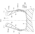
- the rear first portion B1 is placed between the midsole 2 and the top line 20 of the upper 1.
- the second portion B2 is placed along the boundary portion 10 between the rear end portion 15 of the upper 1 and the midsole 2.
- the rear second portion B2 extends to the midsole 2, and includes the rear tucked end portion BE that is tucked between the midsole 2 and the upper 1.
- the bridge 40 on the rear center portion of FIG. 3 vertically connects between the center of the rear first portion B1 and the center of the rear second portion B2. That is, the bridge 40 is placed directly behind the calcaneal bone B9 of FIG. 1 .
- the rear end portion 15 of the upper 1 is an extent of 20%, preferably 10%, extending from a rear end 1E of the upper with respect to the entire length 100% of the upper on the sagittal plane.
- the rear first portion B1 and the rear second portion B2 of FIG. 3 extend in the lateral direction while being curved along the upper.
- the medial bridge 41 diagonally connects between the rear first portion B1 and the rear second portion B2.
- the lateral bridge 42 diagonally connects between the rear first portion B1 and the rear second portion B2.
- a rear through hole Bh which appears to be a window, may be provided between the three bridges 40 to 42, as shown in FIG. 3 .
- the lateral first portion L1, the lateral bridge 42, the rear first portion B1 and the rear second portion B2 define a closed window area ⁇ 2, and the heel counter 4 defines the rear through hole Bh running through the heel counter 4 in the window area ⁇ 2.
- the lateral first portion L1 extends toward the midsole 2 below and toward the diagonal anterior direction reaching the midsole 2.
- the heel counter 4 includes the lateral tucked end portion LE that is tucked between the midsole 2 and the upper 1.
- the lateral tucked end portion LE is formed by the lateral first portion L1 extending toward the midsole 2 and toward the anterior direction X1 reaching the midsole 2 so as to be tucked between the midsole 2 and the upper 1.
- the heel counter 4 is not placed in the lateral side boundary portion 120 of the upper 1.
- the lateral side boundary portion 120 includes an exposed portion 121 that is exposed and not covered by the heel counter 4.
- the lateral first portion L1, the lateral bridge 42, the rear second portion B2 and the midsole 2 define a closed lower area ⁇ 1, and the exposed portion 121 is placed in the lower area ⁇ 1.
- lateral side boundary portion 120 means the vicinity of the boundary between the lateral side 12 of the upper 1 and the midsole 2.
- the medial first portion M1 extends toward the midsole 2 below and toward the diagonal anterior direction reaching the midsole 2, and is continuous with the medial second portion M2.
- the medial second portion M2 extends toward the anterior direction from the rear second portion B2 along the medial side boundary portion 110 to be continuous with the medial first portion M1.
- a medial through hole Mh which appears to be a window, may be provided between the medial first portion M1 and the medial second portion M2 which are arranged in the vertical direction.
- medial side boundary portion 110 means the vicinity of the boundary between the medial side 11 of the upper 1 and the midsole 2.
- the medial tucked end portion ME which generally is a lower half of the medial second portion M2, is tucked between the midsole 2 and the upper 1.
- the tucked end portion ME is the medial second portion M2 tucked between the sole 2 and the upper 1, and connects together the rear second portion B2 and the lower end portion of the medial first portion M1.
- an exposed portion M21 which generally is an upper half of the medial second portion M2 of FIG. 1 , covers the medial side boundary portion 110 of the upper 1 and is exposed.
- the value of the flexural rigidity fEIz of the medial first portion M1 is greater than the value of the flexural rigidity fEIz of the lateral first portion L1.
- the value of the moment of inertia of area Iz of the medial first portion M1 is greater than the value of the moment of inertia of area Iz of the lateral first portion L1.
- the thickness of the medial first portion M1 of FIG. 5 is greater than the thickness of the lateral first portion L1.
- the moment of inertia of area Iz has such a correlation that it is in proportion to the cube of the thickness.
- the medial first portion M1 and the lateral first portion L1 of FIG. 3 are formed from the same material. Therefore, the medial first portion M1 and the lateral first portion L1 have an equal Young's modulus (longitudinal elastic modulus) E.
- the medial second portion M2 is placed on the medial side boundary portion 110 of FIG. 1 , whereas a member that corresponds to the medial second portion M2 ( FIG. 1 ) is not placed on the lateral side boundary portion 120 of FIG. 2 . That is, the medial second portion M2 is placed on the medial side boundary portion 110 of FIG. 1 so that the medial side boundary portion 110 of FIG. 1 is less flexural deformable than the lateral side boundary portion 120 of FIG. 2 .
- the medial first portion M1, the medial second portion M2 and the bridge 41 are formed to be continuous with each other in a loop shape.
- the loop-shaped portion increases the average flexural rigidity of the lower portion of the upper from the rear end of the talus bone B8 to the front end of the lateral malleolus Ml ( FIG. 2 ).
- the loop-shaped heel counter 4 of FIG. 1 makes the medial first portion M1 less flexurally deformable than the lateral first portion L1 of FIG. 2 .
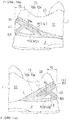
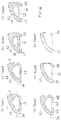
- the shoe of Type 1 of FIG. 6 includes a heel counter that has generally the same shape on the medial side and on the lateral side.
- the lateral side and the medial side of Type 1 have a similar structure to that of the medial side of the heel counter of Embodiment 1. That is, the rigidity of the heel portion of the upper of Type 1 is generally the same on the medial side and on the lateral side.
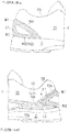
- the shoes of Types 2 to 5 were made by partially cutting off the lateral portion and the back portion of the heel counter of Type 1. Note that the medial portions of the shoes of Types 2 to 5 are similar to those of the heel counter of Type 1.
- the heel counter of Type 2 is obtained by being cut off at the lateral side boundary portion 120 ( FIG. 2 ) between the upper of the heel portion lateral side and the midsole 2.
- the heel counter of Type 3 is obtained by partially cutting off the lateral side while leaving at the lateral side boundary portion 120 ( FIG. 2 ), the rear first portion and the rear second portion.
- the heel counter of Type 4 is obtained by cutting off most of the lateral side while leaving the rear first portion and the rear second portion.
- the heel counter of Type 5 is obtained by cutting off most of the rear first portion and the entire lateral side.
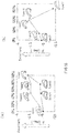
- the pronation (the heel portion eversion angle ⁇ and the lower leg internal rotation angle ⁇ ) and the heel portion holding property (the evaluation value Disp.Z of the foot following property during the latter half of the support period) were measured while actually running. The results are shown in FIG. 7 to FIG. 9 .
- the evaluation value Disp.Z of the following property is the vertical displacement of the foot with respect to the shoe. Therefore, the maximum value of Disp.Z, which is observed during heel rise, is measured as the evaluation value Disp.Zmax, wherein the value being smaller means a better following property and a higher heel portion holding property.
- Type 2 and Type 5 have smaller absolute values than Type 1
- Type 2 and Type 5 have smaller absolute values than Type 1
- Type 4 and Type 5 have smaller absolute values than Type 1, i.e., an improvement in the stability property.
- the heel counter is present in the lateral side boundary portion 120 ( FIG. 2 ) of the heel portion lateral side, where the sole first comes into contact with the ground.
- the samples of Types 2, 4 and 5 with an improved stability property described above are obtained by the heel counter being cut off at the lateral side boundary portion 120 ( FIG. 2 ).
- the low rigidity of the lateral side boundary portion 120 ( FIG. 2 ) increases the deformation of the sole upon landing. It is believed that this suppresses the speed at which the foot collapses toward the medial side and decreases the pronation to be exhibited thereafter. That is, it is believed that the absolute value of the heel portion eversion angle ⁇ of FIG. 7 and the absolute value of the lower leg internal rotation angle ⁇ of FIG. 8 are small, thereby improving the stability property.
- the counter is cut off not only on the lateral side but also on the back side, thereby lowering the flexural rigidity of an area upon which a force acts directly. It is believed that the heel portion deformation is thus greater as compared with Type 3 and Type 4, resulting in the lowest heel portion holding property among all the samples.
- FIG. 14 shows the lateral side of the heel counter.
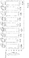
- the heel counters of Type 21 of FIG. 14(a) and Type 22 of FIG. 14(b) are provided with a lateral through hole Lh that is larger than the medial through hole Mh ( FIG. 1 ).
- the lower end of the lateral through hole Lh is set to be generally at the midsole upper edge 2e.
- the lower end of the lateral through hole Lh is set to be below the midsole upper edge 2e.
- the heel counters of Types 23 and 24 of FIGS. 14(c) and 14(d) have the lateral second portion L2 that connect together the lateral tucked end portion LE and the rear tucked end portion BE.
- the lower end of the lateral second portion L2 is set to be around the midsole upper edge 2e.
- the lower edge of the lateral second portion L2 is set to be above the midsole upper edge 2e.
- the heel counter of Type 25 of FIG. 14(e) is obtained by cutting off about 1/3 of the central portion of the lateral second portion L2 of the heel counter of Type 21 of FIG. 14(a) .
- the heel counter of Type 26 of FIG. 14(f) has a structure obtained by cutting off a rear upper portion on the lateral side of the heel counter of Type 2 of FIG. 6 .
- the heel counter of Type 27 of FIG. 14(g) has a structure obtained by partially cutting off a rear upper portion and a rear second portion on the lateral side of the heel counter of Type 2 of FIG. 6 .
- the heel portion eversion angle ⁇ was measured while actually running. The results are shown in FIG. 15 and FIG. 16 .
- FIGS. 16(a) and 16(b) show the heel portion eversion angle ⁇ for the various samples, wherein the horizontal axis of the graphs represents the cut-off percentage in the vertical direction and the foot longitudinal direction, respectively, of the lateral second portion L2 ( FIG. 14 ).
- FIG. 10A and FIG. 10B show Embodiment 2.
- the quarter 13 of the upper includes a main member 13a and a reinforcement member 13b.
- the main member 13a is placed over more than a half or most of the quarter 13, covering the medial side and the lateral side of the foot.
- the reinforcement member 13b is provided in the hatched area of the quarter 13, for example, and may be stacked on the surface of the main member 13a or may be provided by impregnating the main member 13a with a resin.
- the main member 13a may be, for example, a mesh material having a lattice structure (mesh structure), a knit fabric, a woven fabric, or the like. These materials are more stretchable than the reinforcement member 13b.
- the reinforcement member 13b of the medial side 11 of FIG. 10A is placed along the medial first portion M1 of the heel counter 4.
- the reinforcement member 13b of the lateral side 12 of FIG. 10B forms a part of the reinforcement device, and forms the lateral first portion L1 together with the heel counter 4.
- the reinforcement member 13b of the lateral side 12 is placed on the lateral side boundary portion 120.
- the reinforcement member 13b of the lateral side boundary portion 120 forms the lateral second portion L2. Therefore, the lateral side boundary portion 120 has a higher tensile rigidity than a portion where only the main member 13a is placed, and has a lower flexural rigidity than the medial side boundary portion 110 of FIG. 10A .
- the heel counter 4 of FIG. 10A and FIG. 10B is not provided with a bridge on the rear center portion.
- the lateral first portion L1 of the heel counter 4 extends toward the midsole 2 toward the anterior direction, but does not extend up to the midsole 2.
- the width W L of the lateral first portion L1 of the heel counter 4 is greater than the width W M of the medial first portion M1.
- the lateral first portion L1 of the heel counter 4 has a free end on the front side of the rear end portion 15. Therefore, on the front side of the rear end portion 15, the lateral first portion L1 of the heel counter 4 is more flexurally deformable than the medial first portion M1 of FIG. 10A .
- the bridges 41 and 42 of the medial side 11 and the lateral side 12 support the rear first portion B1, and therefore the compressive rigidity of the rear end portion 15 of the upper is high.
- FIG. 11A and FIG. 11B show Embodiment 3.
- the reinforcement member 13b may be provided only on the lateral side 12.
- the heel counter 4 is formed in a loop shape on the medial side 11 and the lateral side 12.
- the lateral first portion L1 is formed by the heel counter 4 and the reinforcement member 13b.
- the lower portion of the lateral first portion L1 and the lateral side boundary portion 120 are formed from the reinforcement member 13b of the upper, and therefore the lateral first portion L1 is more flexurally deformable than the medial first portion M1.
- FIG. 12A to FIG. 12C show Embodiment 4.
- the heel counter 4 of the present embodiment is formed from a tape material.
- the heel counter 4 of the tape material may be bonded and sewn onto the main member of the quarter 13.
- the tape material has a greater Young's modulus than the main member of the quarter 13, and is therefore less stretchable and less bendable than the main member.
- the rear second portion B2 may not be provided on the rear center portion, and may be provided only on the medial side 11 of FIG. 12A .
- the rear second portion B2 is provided in the rear end portion 15, which is a 20% area of the medial side 11 extending from the rear end 1E.
- FIG. 13A and FIG. 13B show Embodiment 5.
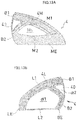
- This embodiment is provided with the lateral second portion L2 that connects together the tucked end portion LE of the lateral first portion L1 and the rear second portion B2 of the heel counter 4 of Embodiment 1.
- the lateral second portion L2 will slightly reinforce a part of the lateral side boundary portion 120 of FIG. 2 , and slightly reinforce the midsole 2 directly under the lateral side boundary portion 120.
- the lateral second portion L2 of the heel counter 4 of FIG. 13B is tucked between the upper 1 and the midsole 2 of FIG. 2 and not exposed to the outside.
- a part or whole of the heel counter 4 may be exposed on the upper 1 or may be buried in the upper 1. Where a part or whole of the heel counter 4 is exposed on the upper 1, it is expected to further improve the stability property and the following property, and is expected to ensure the safety of the upper as a whole.
- FIG. 17 to FIG. 21 show Embodiment 6.
- the shoe includes the upper 1, the midsole 2, the outsole 3 and the heel counter 4.
- the upper 1 includes the lateral side boundary portion 120 between the upper 1 and the sole 2 on the lateral side 12 of the upper of FIG. 18 , the medial side boundary portion 110 between the upper 1 and the sole 2 on the medial side 11 of the upper of FIG. 17 , and the rear boundary portion 10 between the upper 1 and the sole 2 in the rear end portion 15 of the upper of FIG. 19 .
- the medial side boundary portion 110 ( FIG. 17 ) and the lateral side boundary portion 120 ( FIG. 18 ) are continuous with each other with the rear boundary portion 10 interposed therebetween, as shown in FIG. 19 .
- the heel counter 4 made of a thermoplastic resin is attached to the outer surface of the upper 1, as shown in FIG. 20A and FIG. 20B . As shown in FIG. 21 , the heel counter 4 includes the rear first portion B1, the rear second portion B2, the lateral first portion L1, the medial first portion M1 and the medial second portion M2, which are integrally and seamlessly continuous with each other.
- the rear first portion B1 of FIG. 18 is placed between the sole 2 and the top line 20 of the upper 1, in the rear end portion 15 of the upper.
- the rear second portion B2 is placed in the rear boundary portion 10. As shown in FIG. 19 , the rear first portion B1 and the rear second portion B2 of the present embodiment are vertically continuous with each other on the back surface of the upper.
- the lateral first portion L1 is continuous with the rear first portion B1, and is formed in a strip shape extending on the lateral side 12 of the upper toward the sole 2 and toward the diagonal anterior-downward direction.
- the medial first portion M1 of FIG. 17 is continuous with the rear first portion B1, and extends toward the sole 2 on the medial side 11 of the upper.
- the medial second portion M2 is continuous with the rear second portion B2, and extends on the medial side 11 of the upper along the medial side boundary portion 110 from the rear second portion B2 toward the anterior direction X1.
- the medial first portion M1, the medial second portion M2, the rear second portion B2 and the rear first portion B1 are continuous with each other, with no through holes or cutouts provided therebetween.
- the lateral first portion L1 of FIG. 18 extends toward the sole 2 and toward the anterior direction X1 reaching the sole 2, and includes the lateral tucked end portion LE that is tucked between the sole 2 and the upper 1.
- the rear end of the lateral tucked end portion LE and the front end of the rear tucked end portion BE are unconnected and separated from each other in the anterior-posterior direction X. That is, in the case of the present embodiment, the lateral tucked end portion LE and the rear tucked end portion BE are continuous with each other by the strip-shaped lateral first portion L1 and the strip-shaped lateral bridge 42, but are not continuous with each other below these strip-shaped members.
- the rear second portion B2 of FIG. 19 extends to the sole 2, and includes the rear tucked end portion BE that is tucked between the sole 2 and the upper 1.
- the medial second portion M2 of FIG. 17 includes the medial tucked end portion ME that is tucked between the sole 2 and the upper 1 and connects together the rear second portion B2 and the lower end portion of the medial first portion M1.
- the heel counter 4 includes the lateral bridge 42 that extends toward the diagonal anterior-upward direction from the rear second portion B2 to the lateral first portion L1. Between the lateral bridge 42 and the lateral first portion L1 and the sole 2, the exposed portion 121 is provided where the lateral side boundary portion 120 of the upper 1 is exposed.
- the lateral first portion L1, the lateral bridge 42, the rear second portion B2 and the sole 2 of FIG. 18 define the closed lower area ⁇ 1.
- the lower area ⁇ 1 is formed as a cutout of the heel counter 4.
- the exposed portion 121 is placed in the lower area ⁇ 1.
- the lower area ⁇ 1 and the exposed portion 121 are shaped so as to protrude upward.
- Examples of the structure in which the flexural rigidity lowers gradually toward the lateral side boundary portion include, in addition to the upwardly-protruding exposed portion of the present embodiment, structures where the volume of a low-rigidity portion, such as an exposed portion or a thin portion having a small thickness, increases gradually downward.
- the lateral first portion L1, the lateral bridge 42, the rear first portion B1 and the rear second portion B2 define the closed window area ⁇ 2.
- the heel counter 4 defines the rear through hole Bh running through the heel counter 4.
- the areas ⁇ 1 and ⁇ 2, which are through holes, are not provided in the medial portion 4M of FIG. 17 .
- the heel counter 4 may include a projecting portion 49 in the medial portion 4M of FIG. 17 and the lateral portion 4L of FIG. 18 .
- the projecting portion 49 extends on the lateral portion 4L in the diagonal anterior-upward direction from the lateral bridge 42 toward the top line 20 to intersect with the lateral first portion L1.
- FIG. 22 to FIG. 26 show Embodiment 7.
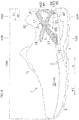
- the reinforcement device includes both a built-in heel counter 4 and an external heel counter 400.
- the built-in heel counter 4 has a functional feature, and the external heel counter 400 has a design feature.
- the external heel counter 400 is attached to the outer surface of the rearfoot portion of the upper 1.
- the upper 1 includes an inner skin 14 placed on the side that comes into contact with the foot, and an outer skin 13 on the opposite side.
- the built-in heel counter 4 is built in between the inner skin 14 and the outer skin 13.
- FIG. 25A and FIG. 25B are cross sections as seen from the front side of the shoe.
- the midsole 2 of FIG. 22 and FIG. 23 is not shown.
- the built-in heel counter 4 is sandwiched between the upper 1 (the inner skin 14 ) and the midsole 2.
- the built-in counter 4 includes the rear first portion B1, the rear second portion B2, the lateral first portion L1, the medial first portion M1 and the medial second portion M2, which are integrally and seamlessly continuous with each other.
- the built-in counter 4 is plate-shaped as a whole and further includes a low-rigidity portion LW whose rigidity is lower than that of the medial first portion M1 and the medial second portion M2, wherein the low-rigidity portion LW is surrounded by the rear first portion B1, the rear second portion B2 and the lateral first portion L1.
- the built-in counter 4 of FIG. 23 is plate-shaped as a whole and includes the lateral second portion L2.
- the lateral second portion L2 is continuous with the rear second portion B2, and extends on the lateral side 12 of the upper along the lateral side boundary portion 120 from the rear second portion B2 toward the anterior direction X1.
- the built-in counter 4 includes a lateral central portion LC surrounded by the rear first portion B1, the rear second portion B2, the lateral first portion L1 and the lateral second portion L2.
- the lateral central portion LC defines a thin portion having a smaller thickness than the surrounding portions, one or more slits, or one or more through holes.
- the lateral central portion LC is shown to be a thin portion having a smaller thickness than the surrounding portions. Examples where the lateral central portion LC defines one or more slits or one or more through holes will be described later.
- the built-in counter 4 includes a medial central portion MC surrounded by the rear first portion B1, the rear second portion B2, the medial first portion M1 and the medial second portion M2.
- the built-in counter 4 is plate-shaped as a whole and includes the medial portion 4M placed on the medial side and the lateral portion 4L placed on the lateral side, which are seamlessly continuous with each other.
- the thickness of the lateral central portion LC is smaller than the thickness of the medial central portion MC.
- the average thickness of the lateral portion 4L is smaller than the average thickness of the medial portion 4M.
- the lateral central portion LC of the lateral portion 4L of FIGS. 26(c) and 26(f) is a thin portion as shown in FIG. 26(g) , and the thin portion further includes a plurality of closed grooves extending in the anterior-posterior direction of the foot.
- the low-rigidity portion LW is formed.
- FIG. 27 shows another example of the structure of the lateral portion 4L of the built-in heel counter 4 of FIG. 26(c) .
- the lateral portion 4L of the heel counter 4 may include one through hole 4H or a plurality of through holes 4H arranged in a scattered pattern provided in the lateral central portion LC.
- the built-in counter 4 may be plate-shaped as a whole with a lower edge, and the lower edge may be formed in an upward arch shape between the lateral tucked end portion LE and the rear tucked end portion BE.
- the through holes 4H may be groove-shaped extending in the anterior-posterior direction in the lateral central portion LC.
- the grooves may have the same length or different lengths.
- the direction in which the slits extend may be inclined, and there is no limitation on the direction of inclination.
- the number of groove-shaped through holes 4H may be one, though it is not shown in the figures.
- the through holes 4H may be triangular or polygonal.
- the through hole 4H may be a thin portion that is thin and recessed, thereby forming the low-rigidity portion LW.
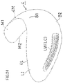
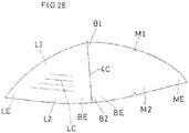
- FIG. 28 shows another example of a built-in heel counter.
- the heel counter 4 has a flat plate shape, and is built in the rearfoot portion of the upper while being bent along a center line 4C into a generally U-letter shape.
- the counter 4 may include a low-rigidity portion LW formed in the lateral central portion LC by providing a plurality of slits in the lateral central portion LC.
- the slits may extend in the anterior-posterior direction in the lateral central portion LC. Also in this case, there may be one slit or a plurality of slits.
- no external heel counter may be provided.
- FIG. 29 shows, together with a part of the upper 1, another example of an external heel counter 4.
- a thin portion 400 is provided to extend from the rear end of the external heel counter 4 toward the medial side and the lateral side.
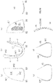
- the distance 40M from the rear end to the front end of the thin portion 400 in the medial portion 4M of FIG. 29(a) is shorter than the distance 40L in the lateral portion 4L of FIG. 29(b).
- the external heel counter 4 is dotted, and the thin portion 400 are densely dotted.
- a pattern of small protrusions/depressions may be provided in a portion of the external heel counter 4.
- the external heel counter 4 is provided with eyelets 401 through which shoelaces are passed.
- a through hole 402 may be provided in the vicinity of the eyelets 401.
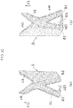
- FIG. 30 shows still another example of the external heel counter 4.
- a bridge 404 forming a through hole 403 is provided to extend from the rear end of the external heel counter 4 to the lateral side and the medial side.
- the lateral portion 4L of FIG. 30(a) has a lower rigidity than the medial portion 4M of FIG. 30(b) .
- the sole placed under the upper may include only a so-called "outsole".
- the heel counter When the heel counter is a built-in heel counter, the heel counter may be a thick cardboard or a cardboard impregnated with a resin, as well as a thermoplastic resin.
- the present invention is applicable to athletic shoes such as running shoes and also to various other types of shoes such as walking shoes.
Landscapes
- Health & Medical Sciences (AREA)
- Epidemiology (AREA)
- General Health & Medical Sciences (AREA)
- Public Health (AREA)
- Footwear And Its Accessory, Manufacturing Method And Apparatuses (AREA)
Abstract
Description
- The present invention relates to a shoe including a reinforcement device reinforcing a heel portion of an upper.
- A heel counter, which is an example of a reinforcement device, covers the opposite side surfaces and the rear surface of the heel and maintains the shape of the heel portion of the upper. When the entire heel is wrapped around by the heel counter formed from a resin part, the heel portion of the upper has a high rigidity, but it inhibits the deformation of the upper in conformity with the shape of the heel of the wearer. That is, the fitting property of the heel portion deteriorates.
- For example, heel counters formed in lattice shapes are known in the art, as described in the patent documents identified below. Moreover, heel counters having different shapes on the lateral side and on the medial side are known in the art.
-
- First Patent Document:
WO2010/038267 A1 (FIGS. 1 and2 ) - Second Patent Document:
JP2005-296101/A1 FIG. 3 ) - It is an object of the present invention to provide a reinforcement device of an upper of a shoe that improves the stability property and the following property (the conforming property) of the shoe from landing to takeoff while running.
- A shoe in one aspect of the present invention includes: an upper 1, a
reinforcement device 4 reinforcing the upper 1, and a sole 2 attached to the upper 1, wherein: - the upper 1 includes a lateral
side boundary portion 120 between the upper and the sole 2 on alateral side 12 of the upper, a medialside boundary portion 110 between the upper and thesole 2 on amedial side 11 of the upper, and arear boundary portion 10 between the upper and the sole 2 in arear end portion 15 of the upper; - the medial
side boundary portion 110 and the lateralside boundary portion 120 are continuous with each other via therear boundary portion 10; and - the
reinforcement device 4 includes:- a rear first portion B1 placed between the sole 2 and a top line (a collar or a wearing opening) 20 of the upper 1 in a
rear end portion 15 of the upper; - a rear second portion B2 placed in the
rear boundary portion 10; - a lateral first portion L1 being continuous with the rear first portion B1 and extending toward the sole 2 on the
lateral side 12 of the upper; - a medial first portion M1 being continuous with the rear first portion B1 and extending toward the sole 2 on the
medial side 11 of the upper, the medial first portion M1 being less flexurally deformable than the lateral first portion L1; and - a medial second portion M2 being continuous with the rear second portion B2 and extending toward an anterior direction from the rear second portion B2 along the medial
side boundary portion 110 on themedial side 11 of the upper so that the medialside boundary portion 110 is less flexurally deformable than the lateralside boundary portion 120.
- a rear first portion B1 placed between the sole 2 and a top line (a collar or a wearing opening) 20 of the upper 1 in a
- With ordinary athletic shoes, a resin-made or resin-impregnated member, called a heel counter, is arranged on the medial and lateral sides of the heel portion. A heel counter maintains the shape of the shoe, and suppresses the pronation of the subtalar joint that occurs during the support period after landing. The flexural rigidity of the medial side of the heel counter substantially contributes to the suppression of the pronation, and it serves to support, by means of the medial side of the upper, the foot being urged to collapse toward the medial side. The medial first portion M1 and the medial
side boundary portion 110, which are less flexurally deformable than the lateral first portion L1, will serve to suppress the pronation and improve the stability property. - The foot, which lands starting from the lateral side of the heel portion, exhibits pronation thereafter. The lateral
side boundary portion 120 is more flexurally deformable and more compressively deformable than the medialside boundary portion 110, thereby increasing the amount of deformation of the lateralside boundary portion 120 upon heel contact. As a result, it is expected to suppress the speed at which the foot collapses toward the medial side and decrease the pronation to be exhibited thereafter. - In the latter half of the support period, the heel rises entailing the weight transfer, the forefoot portion of the sole dorsiflexes, and a restoring force occurs in the sole in such a direction that urges the rearfoot portion of the sole away from the foot. At this point, the upper is required to have a good foot fitting property, and particularly, the heel portion of the sole and that of the upper are required to have a good foot following property during the latter half of the support period. At this point, the force that acts upon the upper from the foot is a force that pushes the back side (the rear end portion) of the heel portion of the upper in the direction normal to the upper surface. Therefore, there is a demand for the back side of the heel portion of the shoe to have a structure that suppresses the deformation against such a force.
- In view of this demand, in the present invention, the rear first portion and the rear second portion placed on the rear end portion of the upper increase the rigidity of the back side of the heel portion, thereby suppressing the deformation of the heel portion. This will improve the following property.
- The lateral first portion L1, which is more flexurally deformable than the medial first portion M1, extends from the rear first portion B1 toward the sole 2. Therefore, the lateral first portion L1 suppresses the stretch of the heel portion lateral side in the direction that connects between the lower portion of the upper below the ankle and the rear first portion B1 without excessively increasing the flexural rigidity of the heel portion lateral side. This suppresses the deformation due to a force that pushes the back side (the rear end portion) of the heel portion of the upper in the direction normal to the upper surface. This as a result will improve the following property.
- As described above, the present invention is expected to improve the stability property and the foot following property during the support period.
- The rear first portion and the rear second portion increase the rigidity of the back side of the upper. In view of this, "the rear end portion of the upper", where the rear first portion and the rear second portion are placed, means an extent of 20% or less extending from the rear end of the upper with respect to the entire length (the length of the shoe in the longitudinal direction) 100% of the upper on the sagittal plane. This is because when the reinforcement device is placed in such an extent, it is possible to increase the rigidity of the back side of the upper. Therefore, it is preferred that at least a portion of the rear first portion and the rear second portion is placed in the rear end portion, which is the 20% extending from the rear end of the upper. It is preferred that at least a portion of the rear first portion is placed in an extent of 10% or less from the rear end of the upper and at least a portion of the rear second portion is placed in an extent of 20% or less. It is more preferred that at least a portion of the rear first portion is placed in an extent of 10% or less from the rear end of the upper and at least a portion of the rear second portion is placed in an extent of 15% or less. It is particularly preferred that at least a portion of the rear first portion and at least a portion of the rear second portion are both placed in an extent of 10% or less from the rear end of the upper.
- The medial side refers to the side that is closer to the median on the frontal plane of the body, and is commonly referred to often as the inner side or the inner side of the foot. The lateral side refers to the side that is farther away from the median on the frontal plane of the body, and is commonly referred to often as the outer side or the outer side of the foot.
- Being less flexural deformable includes cases where the flexural rigidity fEIz is higher, and also cases where the reinforcement device is formed in a loop shape and has less deformation due to bending moment.
- The flexural rigidity means the integral value ∫EIz of the Young's modulus (longitudinal elastic modulus) E and the moment of inertia of area Iz of the member.
- Each first portion and the corresponding second portion may be vertically continuous with each other or vertically separated from each other. The medial first portion and the medial second portion may have a window (through hole) therebetween, or may be continuous with each other in a flat plate shape. A lateral second portion having a thin plate shape may be provided also on the lateral side.
-
-
FIG. 1 is a schematic side view of the medial side showing an athletic shoe ofEmbodiment 1 of the present invention. -
FIG. 2 is a schematic side view of the lateral side showing the athletic shoe ofEmbodiment 1. -
FIG. 3 is a back view showing the athletic shoe of Embodiment 1. -
FIG. 4 is a IV-IV cross section of an upper according toEmbodiment 1. -
FIG. 5 is a V-V cross section of the upper according toEmbodiment 1. -
FIG. 6 is a side view and a back view of the lateral side showing 5 types of shoes used in a test. -
FIG. 7 is a bar graph showing the measurement result of the heel eversion angle β after landing. -
FIG. 8 is a bar graph showing the measurement result of the lower leg internal rotation angle (the lower leg inversion angle) γ after landing. -
FIG. 9 is graphs showing the measurement method and the measurement result of the displacement of the heel with respect to the shoe. -
FIG. 10A is a side view of the medial side of the rearfoot portion of a shoe according toEmbodiment 2, andFIG. 10B is a side view of the lateral side of the rearfoot portion of the shoe according toEmbodiment 2. -
FIG. 11A is a side view of the medial side of the rearfoot portion of a shoe according toEmbodiment 3, andFIG. 11B is a side view of the lateral side of the rearfoot portion of the shoe according toEmbodiment 3. -
FIG. 12A is a side view of the medial side of the rearfoot portion of a shoe according toEmbodiment 4,FIG. 12B is a back view of the shoe according toEmbodiment 4, andFIG. 12C is a side view of the medial side of the rearfoot portion of the shoe according toEmbodiment 4. -
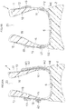
FIG. 13A and FIG. 13B are side views of the medial side and the lateral side, respectively, showing another example of a heel counter. -
FIG. 14 is a side view of the lateral side showing other seven types of heel counters used in a test. -
FIG. 15 is a bar graph showing the measurement result of the heel eversion angle β after landing from the test. -
FIG. 16 shows the relationship between the cut-off percentage in the vertical direction or the foot longitudinal direction and the angle β. -
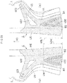
FIG. 17 is a schematic side view of the medial side showing an athletic shoe ofEmbodiment 6 of the present invention. -
FIG. 18 is a schematic side view of the lateral side showing the athletic shoe ofEmbodiment 6. -
FIG. 19 is a back view showing the athletic shoe ofEmbodiment 6. -
FIG. 20A is a XXA-XXA cross section of an upper according toEmbodiment 6, andFIG. 20B is a XXB-XXB cross section of the upper according toEmbodiment 6. -
FIG. 21 is a perspective view of a heel counter according toEmbodiment 6 as seen from the medial side. -
FIG. 22 is a schematic side view of the medial side showing an athletic shoe ofEmbodiment 7 of the present invention. -
FIG. 23 is a schematic side view of the lateral side showing the athletic shoe ofEmbodiment 7. -
FIG. 24 is a perspective view showing a heel counter ofEmbodiment 7. -
FIG. 25A is a XXVA-XXVA cross section of an upper according toEmbodiment 7, andFIG. 25B is a XXVB-XXVB cross section of the upper according toEmbodiment 7. -
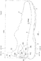
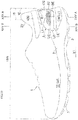
FIG. 26 shows a medial side view, a bottom view, a lateral side view, a vertical section, an e-e cross section, an f-f cross section and an enlarged cross section showing the heel counter ofEmbodiment 7. -
FIG. 27 relates to another example of a built-in heel counter, and is a lateral side view showing the structure of a low-rigidity portion of the lateral side. -
FIG. 28 relates to another example of a built-in heel counter, and is a plan view showing an unmolded state. -
FIG. 29 is a medial side view and a lateral side view showing another example of an external heel counter. -
FIG. 30 is a lateral side view and a medial side view showing still another example of an external heel counter. - In
FIG. 1 to FIG. 6 ,FIG. 10A to FIG. 13A ,FIG. 17 to FIG. 20A ,FIG. 25A and FIG. 25B , heel counter areas are dotted. - Preferably, the lateral first portion L1 extends toward the sole 2 and toward the anterior direction reaching the sole 2, the lateral first portion L1 (the reinforcement device 4) further including a lateral tucked end portion LE tucked between the sole 2 and the upper 1.
- The lateral tucked end portion of the lateral first portion is tucked between the sole and the upper, and the lateral first portion increases the tensile rigidity between the lower end of the upper and the rear end portion of the upper below the lateral malleolus of the heel portion. This will improve the following property.
- Preferably, the
reinforcement device 4 includes aheel counter 4 made of a thermoplastic resin; and
theheel counter 4 includes the rear first portion B1, the rear second portion B2, the medial first portion M1 and the medial second portion M2, which are integrally continuous with each other. - In this case, it is easy to manufacture the reinforcement device.
- Preferably, the
heel counter 4 further integrally (and seamlessly) includes the lateral first portion L1. - In this case, it is even easier to manufacture the reinforcement device.
- Preferably, a moment of inertia of area of the medial first portion M1 is greater than a moment of inertia of area of the lateral first portion L1.
- The moment of inertia of area Iz of the lateral first portion L1 is smaller than the moment of inertia of area Iz of the medial first portion M1. Therefore, it is easy to lower the flexural rigidity of the upper on the lateral side of the heel portion. As a result, the pronation will be decreased as described above.
- Preferably, the lateral first portion L1 is formed from a tape material separate from the
heel counter 4. - The tape material has a lower flexural rigidity than the heel counter, and gives a high tensile rigidity. Therefore, the upper on the lateral side of the heel portion has a low flexural rigidity, thereby decreasing the pronation. Since the tensile rigidity is high, a high following property will be exhibited.
- Preferably, the
heel counter 4 is absent (not provided) in the lateralside boundary portion 120 of the upper 1. - In this case, the flexural rigidity on the lateral side of the heel portion is low.
- A shoe in another aspect of the present invention includes: an upper 1, a
reinforcement device 4 reinforcing the upper 1, and a sole 2 attached to the upper 1, wherein: - the upper 1 includes a lateral
side boundary portion 120 between the upper and the sole 2 on alateral side 12 of the upper, a medialside boundary portion 110 between the upper and the sole 2 on amedial side 11 of the upper, and arear boundary portion 10 between the upper and the sole 2 in arear end portion 15 of the upper; - the medial
side boundary portion 110 and the lateralside boundary portion 120 are continuous with each other via therear boundary portion 10; and - the
reinforcement device 4 includes:- a rear first portion B1 placed between the sole 2 and a top line (a collar) 20 of the upper 1 in a
rear end portion 15 of the upper; - a rear second portion B2 placed in the
rear boundary portion 10; - a lateral first portion L1 being continuous with the rear first portion B1 and extending toward the sole 2 on the
lateral side 12 of the upper; - a medial first portion M1 being continuous with the rear first portion B1 and extending toward the sole 2 on the
medial side 11 of the upper; and - a medial second portion M2 being continuous with the rear second portion B2 and extending toward an anterior direction from the rear second portion B2 along the medial
side boundary portion 110 on themedial side 11 of the upper, wherein:- the lateral first portion L1 extends toward the sole 2 and toward the anterior direction reaching the sole 2, the lateral first portion L1 including a lateral tucked end portion LE tucked between the sole 2 and the upper 1;
the medial second portion M2 includes a medial tucked end portion ME that is tucked between the sole 2 and the upper 1 and connects together the rear second portion B2 and a lower end portion of the medial first portion M1.
- a rear first portion B1 placed between the sole 2 and a top line (a collar) 20 of the upper 1 in a
- In this aspect, the medial second portion M2 extending along the medial
side boundary portion 110 includes the medial tucked end portion ME that connects between the rear second portion B2 and the lower end portion of the medial first portion M1, and is therefore less flexural deformable as compared with the lateral side. - The
reinforcement device 4 having such a structure maintains the shape of the shoe, and suppresses the pronation of the subtalar joint that occurs during the support period after landing. Therefore, it serves to support, by means of the medial side of the upper, the foot being urged to collapse toward the medial side. - The foot, which lands starting from the lateral side of the heel portion, exhibits pronation thereafter. The upper on the lateral side having the lateral tucked end portion LE is more flexurally deformable as compared with the upper on the medial side having the medial tucked end portion ME that connects together the rear second portion B2 and the lower end portion of the medial first portion M1.
- That is, the lateral
side boundary portion 120 is more flexurally deformable than the medialside boundary portion 110, thereby increasing the amount of deformation of the lateralside boundary portion 120 upon heel contact. As a result, it is expected to suppress the speed at which the foot collapses toward the medial side and decrease the pronation to be exhibited thereafter. - As described above, in the latter half of the support period, the rear first portion B1 and the rear second portion B2 placed in the rear end portion of the upper increase the rigidity on the back side of the heel portion, thereby suppressing the deformation of the heel portion. This will improve the following property.
- The lateral first portion L1 is more flexurally deformable as compared with the medial side having the medial tucked end portion ME. The lateral first portion L1 suppresses the stretch of the heel portion lateral side in the direction that connects between the lower portion of the upper and the rear first portion B1 below the ankle without excessively increasing the flexural rigidity of the heel portion lateral side. This suppresses the deformation due to a force that pushes the back side (the rear end portion) of the heel portion of the upper in the direction normal to the upper surface. This as a result will improve the following property.
- As described above, the present invention is expected to improve the stability property and the foot following property during the support period.
- Preferably, the
reinforcement device 4 includes aheel counter 4 made of a thermoplastic resin;
theheel counter 4 is attached to an outer surface of the upper 1; and
theheel counter 4 includes a rear first portion B1, a rear second portion B2, a lateral first portion L1, a medial first portion M1 and a medial second portion M2, which are integrally and seamlessly continuous with each other. - In this case, it is easy to manufacture the
reinforcement device 4. - Preferably, a rear end of the lateral tucked end portion LE and a front end of the rear tucked end portion BE are unconnected and separated from each other in an anterior-posterior direction.
- In this case, the upper on the lateral side has a lower flexural rigidity as compared with the upper on the medial side having the medial tucked end portion ME. As a result, the pronation will be decreased as described above.
- Preferably, the
heel counter 4 includes alateral bridge 42 that extends toward a diagonal anterior-upward direction from the rear second portion B2 to the lateral first portion L1; and
a low-rigidity portion is provided between thelateral bridge 42 and the sole 2, the low-rigidity portion having a rigidity lower than that of thelateral bridge 42. - With the structure that includes a low-rigidity portion between the
lateral bridge 42 and the sole 2, it is easy to lower the flexural rigidity of the lateralside boundary portion 120. Therefore, with such a structure, it is easy to decrease the pronation. - Preferably, the
heel counter 4 includes alateral bridge 42 that extends toward a diagonal anterior-upward direction from the rear second portion B2 to the lateral first portion L1; and
an exposedportion 121 is provided between thelateral bridge 42 and the sole 2, and the lateralside boundary portion 120 of the upper 1 is exposed through the exposedportion 121. - With the structure in which the lateral
side boundary portion 120 includes the exposedportion 121, it is easy to lower the flexural rigidity of the lateralside boundary portion 120. Therefore, with such a structure, it is easy to decrease the pronation. - Preferably, the lateral first portion L1, the
lateral bridge 42, the rear second portion B2 and the sole 2 define a closed lower area α1; and
the exposedportion 121 is placed in the lower area α1. - With the structure including the lateral
side boundary portion 120 where the lower area α1 includes the exposedportion 121, it is easy to lower the flexural rigidity of the lower area α1. Therefore, with such a structure, it is easy to decrease the pronation. - Preferably, the lower area α1 and the exposed
portion 121 are shaped so as to protrude upward. - With the structure in which the lower area α1 and the exposed
portion 121 are shaped so as to protrude upward, it is easy to increase the size of the exposedportion 121. Particularly, it is easy to increase the size of the exposedportion 121 near the lateralside boundary portion 120. Therefore, with such a structure, it is easy to lower the flexural rigidity of the lateralside boundary portion 120 and decrease the pronation. - Preferably, the lateral first portion L1, the
lateral bridge 42, the rear first portion B1 and the rear second portion B2 define a closed window area a2; and
in the window area α2, theheel counter 4 defines a rear through hole Bh running through theheel counter 4. - With the
heel counter 4 that defines the rear through hole Bh in the window area α2 on the lateral side, it is easy to lower the flexural rigidity of the upper on the lateral side of the heel portion. Therefore, the pronation will be decreased. - Preferably, the
reinforcement device 4 includes aheel counter 4 made of a thermoplastic resin;
the upper 1 includes an inner skin (14) placed on a side that comes into contact with a foot, and an outer skin (13) on an opposite side of theinner skin 14;
theheel counter 4 is a built-incounter 4 that is built in between the inner skin and the outer skin; and
the built-incounter 4 includes the rear first portion B1, the rear second portion B2, the lateral first portion L1, the medial first portion M1 and the medial second portion M2, which are integrally and seamlessly continuous with each other. - The built-in heel counter is sandwiched between the inner skin and the outer skin of the upper and functions as the core of the upper, and the built-in heel counter will easily serve as a heel counter despite being thin.
- Preferably, the built-in
counter 4 is plate-shaped as a whole and further includes a low-rigidity portion LW whose rigidity is lower than that of the medial first portion M1 and the medial second portion M2, wherein the low-rigidity portion LW is surrounded by (is bordered on) the rear first portion B1, the rear second portion B2 and the lateral first portion L1. - In this case, the low-rigidity portion LW on the lateral side, which is a surrounded area, lowers the flexural rigidity of the upper on the lateral side of the heel portion. Therefore, the pronation will be decreased as described above.
- Preferably, the built-in
counter 4 is plate-shaped as a whole and further includes a lateral second portion L2, the lateral second portion L2 being continuous with the rear second portion B2, and extending on thelateral side 12 of the upper along the lateralside boundary portion 120 from the rear second portion B2 toward the anterior direction;
the built-incounter 4 includes a lateral central portion LC surrounded by the rear first portion B1, the rear second portion B2, the lateral first portion L1 and the lateral second portion L2; and
the lateral central portion LC defines a thin portion having a smaller thickness than surrounding portions, one or more slits, or one or more through holes. - In this case, the lateral central portion LC forms the low-rigidity portion LW, lowering the flexural rigidity of the upper on the lateral side of the heel portion. Therefore, the pronation will be decreased as described above.
- Preferably, the built-in
counter 4 is plate-shaped as a whole and further includes a lateral second portion L2, the lateral second portion L2 being continuous with the rear second portion B2, and extending on thelateral side 12 of the upper along the lateralside boundary portion 120 from the rear second portion B2 toward the anterior direction;
the built-incounter 4 includes a lateral central portion LC surrounded by the rear first portion B1, the rear second portion B2, the lateral first portion L1 and the lateral second portion L2;
the built-incounter 4 includes a medial central portion MC surrounded by the rear first portion B1, the rear second portion B2, the medial first portion M1 and the medial second portion M2; and a thickness of the lateral central portion LC is smaller than a thickness of the medial central portion MC. - With the structure in which the thickness of the lateral central portion LC is smaller than the thickness of the medial central portion MC as described above, the flexural rigidity of the lateral central portion LC is lower than the flexural rigidity of the medial central portion MC. Therefore, such a structure will lower the flexural rigidity of the upper on the lateral side of the heel portion and decrease the pronation as described above.
- Preferably, the built-in
counter 4 is plate-shaped as a whole and includes amedial portion 4M placed on a medial side and alateral portion 4L placed on a lateral side, which are seamlessly continuous with each other; and
an average thickness of thelateral portion 4L is smaller than an average thickness of themedial portion 4M. - With the thin structure, the flexural rigidity of the
lateral portion 4L is lower than the flexural rigidity of themedial portion 4M. Therefore, such a structure will lower the flexural rigidity of the upper on the lateral side of the heel portion and decrease the pronation as described above. - Preferably, the lateral central portion LC includes a plurality of through holes arranged in a scattered pattern.
- The lateral central portion LC having a plurality of through holes forms the low-rigidity portion LW, lowering the flexural rigidity of the upper on the lateral side of the heel portion. Therefore, the pronation will be decreased as described above.
- Preferably, the lateral central portion LC defines a plurality of slits extending in an anterior-posterior direction.
- The lateral central portion LC defining a plurality of slits forms the low-rigidity portion LW, lowering the flexural rigidity of the upper on the lateral side of the heel portion. Therefore, the pronation will be decreased as described above.
- Preferably, the built-in
counter 4 is plate-shaped as a whole with a lower edge; and
the lower edge is formed in an upward arch shape between the lateral tucked end portion LE and the rear tucked end portion BE. - With the structure in which the lower edge of the built-in counter is formed in an upward arch shape on the lateral side, the lateral
side boundary portion 120 is more flexurally deformable than the medialside boundary portion 110. Therefore, the pronation will be decreased as described above. - Preferably, the shoe further includes an external counter attached to an outer surface of a rearfoot portion of the upper 1.
- When an additional external counter is provided in addition to the built-in
counter 4 having the function as described above, it is possible to realize the function-oriented structure of the built-incounter 4 and the design-oriented structure of the external counter. Therefore, it will be advantageous in two ways, i.e., for the function and for the design. - Any feature illustrated and/or depicted in conjunction with one of the aforementioned aspects or the following embodiments may be used in the same or similar form in one or more of the other aspects or other embodiments, and/or may be used in combination with, or in place of, any feature of the other aspects or embodiments.
- The present invention will be understood more clearly from the following description of preferred embodiments taken in conjunction with the accompanying drawings. Note however that the embodiments and the drawings are merely illustrative and should not be taken to define the scope of the present invention. The scope of the present invention shall be defined only by the appended claims. In the accompanying drawings, like reference numerals denote like components throughout the plurality of figures.
- Embodiments of the present invention will now be described with reference to the drawings.
-
FIG. 1 to FIG. 5 show Embodiment 1. - As shown in
FIG. 1 to FIG. 3 , the present athletic shoe includes an upper 1, amidsole 2, anoutsole 3 and a heel counter (reinforcement device) 4. - As shown in
FIG. 4 , the upper 1 includes acushioning material 18 made of a foamed resin between aquarter 13 and a quarter lining 14. Note that thequarter 13 and the quarter lining 14 may be formed from a plurality of layers of fabric. - An
insole 6 is sewn onto the upper 1. On the other hand, the upper 1 ofFIG. 1 includes atop line 20 through which the leg extends upward and through which the foot is inserted. - The upper 1 includes a fastening means such as a shoelace (not shown). The shoelace fastens the upper 1 so that a
medial side 11 of the upper 1 and alateral side 12 ofFIG. 2 are brought into close contact with the foot in the vicinity of thetop line 20. Thereference numeral 16 denotes a tongue provided in front of thetop line 20. - The
medial side 11 of the upper 1 covers the medial surface of the foot. Thelateral side 12 of the upper 1 covers the lateral surface of the foot. Arear end portion 15 of the upper 1 covers the back surface of the foot. Themedial side 11, thelateral side 12 and therear end portion 15 of the upper 1 together form thetop line 20. - In the vicinity of the
top line 20 of the upper 1, themedial side 11 of the upper 1 ofFIG. 1 covers the front end portion B8f of the talus bone B8 and the front end portion J8f of the subtalar joint J8. On the other hand, thelateral side 12 of the upper 1 ofFIG. 2 covers the front end portion B8f of the talus bone B8 and the front end portion J8f of the subtalar joint J8. In the present embodiment, a part of the lateral malleolus Ml and the medial malleolus Mm ofFIG. 1 may each be exposed above thetop line 20. - As shown in
FIG. 4A , theheel counter 4 is bonded and secured with no gap to the outer surface of the upper 1 on themedial side 11 and thelateral side 12 of the upper 1. The upper 1 with theheel counter 4 bonded to the outer surface thereof as described above has a high flexural rigidity and serves to suppress the pronation. - The
midsole 2 and theoutsole 3 ofFIG. 1 are stacked together below theheel counter 4 and theinsole 6. - Next, the
heel counter 4, which is a reinforcement device, will be described. InFIG. 1 to FIG. 5 , theheel counter 4 is dotted. - The
heel counter 4 shown inFIGS. 1 to 3 is bonded to, and partially exposed on, the outer surface of the fabric of the upper 1 to maintain the shape of aheel portion 17 of the soft upper 1, which includes a plurality of layers of fabric and is soft. Thecounter 4 includes themedial portion 4M placed on the medial side and thelateral portion 4L placed on the lateral side, which are integrally and seamlessly continuous with each other. - The
heel counter 4 is formed integrally from a material that includes a thermoplastic resin component. - As shown in
FIG. 1 to FIG. 3 , the medial portion and the lateral portion of theheel counter 4 are formed asymmetric with each other. Theheel counter 4 forms a part or whole of the reinforcement device. Theheel counter 4 includes a lateral tucked end portion LE, a rear tucked end portion BE and a medial tucked end portion ME to be described later. - The
heel counter 4 ofFIG. 3 is made of a thermoplastic resin, and includes a rear first portion B1, a rear second portion B2, a lateral first portion L1, a medial first portion M1 and a medial second portion M2, which are formed integrally continuous with each other. Theheel counter 4 integrally includes threebridges 40 to 42, for example. - As clearly shown in
FIG. 1 andFIG. 3 , in therear end portion 15 of the upper, the rear first portion B1 is placed between themidsole 2 and thetop line 20 of the upper 1. The second portion B2 is placed along theboundary portion 10 between therear end portion 15 of the upper 1 and themidsole 2. Moreover, the rear second portion B2 extends to themidsole 2, and includes the rear tucked end portion BE that is tucked between themidsole 2 and the upper 1. Thebridge 40 on the rear center portion ofFIG. 3 vertically connects between the center of the rear first portion B1 and the center of the rear second portion B2. That is, thebridge 40 is placed directly behind the calcaneal bone B9 ofFIG. 1 . - As shown in
FIG. 1 andFIG. 2 , therear end portion 15 of the upper 1 is an extent of 20%, preferably 10%, extending from arear end 1E of the upper with respect to theentire length 100% of the upper on the sagittal plane. In therear end portion 15, the rear first portion B1 and the rear second portion B2 ofFIG. 3 extend in the lateral direction while being curved along the upper. - In the
rear end portion 15 on the medial side ofFIG. 1 , themedial bridge 41 diagonally connects between the rear first portion B1 and the rear second portion B2. On the other hand, in therear end portion 15 on the lateral side ofFIG. 2 , thelateral bridge 42 diagonally connects between the rear first portion B1 and the rear second portion B2. A rear through hole Bh, which appears to be a window, may be provided between the threebridges 40 to 42, as shown inFIG. 3 . - The lateral first portion L1, the
lateral bridge 42, the rear first portion B1 and the rear second portion B2 define a closed window area α2, and theheel counter 4 defines the rear through hole Bh running through theheel counter 4 in the window area α2. - On the
lateral side 12 ofFIG. 2 , the lateral first portion L1 extends toward themidsole 2 below and toward the diagonal anterior direction reaching themidsole 2. Theheel counter 4 includes the lateral tucked end portion LE that is tucked between themidsole 2 and the upper 1. - The lateral tucked end portion LE is formed by the lateral first portion L1 extending toward the
midsole 2 and toward the anterior direction X1 reaching themidsole 2 so as to be tucked between themidsole 2 and the upper 1. - On the
lateral side 12, theheel counter 4 is not placed in the lateralside boundary portion 120 of the upper 1. In the case of the present embodiment, the lateralside boundary portion 120 includes an exposedportion 121 that is exposed and not covered by theheel counter 4. - The lateral first portion L1, the
lateral bridge 42, the rear second portion B2 and themidsole 2 define a closed lower area α1, and the exposedportion 121 is placed in the lower area α1. - Note that the lateral
side boundary portion 120 means the vicinity of the boundary between thelateral side 12 of the upper 1 and themidsole 2. - On the
medial side 11 ofFIG. 1 , the medial first portion M1 extends toward themidsole 2 below and toward the diagonal anterior direction reaching themidsole 2, and is continuous with the medial second portion M2. On themedial side 11 of the upper, the medial second portion M2 extends toward the anterior direction from the rear second portion B2 along the medialside boundary portion 110 to be continuous with the medial first portion M1. - A medial through hole Mh, which appears to be a window, may be provided between the medial first portion M1 and the medial second portion M2 which are arranged in the vertical direction.
- Note that the medial
side boundary portion 110 means the vicinity of the boundary between themedial side 11 of the upper 1 and themidsole 2. - As shown in the cross sections of
FIG. 4 andFIG. 5 , the medial tucked end portion ME, which generally is a lower half of the medial second portion M2, is tucked between themidsole 2 and the upper 1. The tucked end portion ME is the medial second portion M2 tucked between the sole 2 and the upper 1, and connects together the rear second portion B2 and the lower end portion of the medial first portion M1. On the other hand, an exposed portion M21, which generally is an upper half of the medial second portion M2 ofFIG. 1 , covers the medialside boundary portion 110 of the upper 1 and is exposed. - Regarding the flexural deformation that occurs when the upper collapses in the arrow directions of
FIG. 4 andFIG. 5 , the value of the flexural rigidity fEIz of the medial first portion M1 is greater than the value of the flexural rigidity fEIz of the lateral first portion L1. In the case of the present embodiment, regarding the flexural deformation, the value of the moment of inertia of area Iz of the medial first portion M1 is greater than the value of the moment of inertia of area Iz of the lateral first portion L1. For example, the thickness of the medial first portion M1 ofFIG. 5 is greater than the thickness of the lateral first portion L1. - With such flexural deformation, the moment of inertia of area Iz has such a correlation that it is in proportion to the cube of the thickness.
- In the case of the present embodiment, the medial first portion M1 and the lateral first portion L1 of
FIG. 3 are formed from the same material. Therefore, the medial first portion M1 and the lateral first portion L1 have an equal Young's modulus (longitudinal elastic modulus) E. - The medial second portion M2 is placed on the medial
side boundary portion 110 ofFIG. 1 , whereas a member that corresponds to the medial second portion M2 (FIG. 1 ) is not placed on the lateralside boundary portion 120 ofFIG. 2 . That is, the medial second portion M2 is placed on the medialside boundary portion 110 ofFIG. 1 so that the medialside boundary portion 110 ofFIG. 1 is less flexural deformable than the lateralside boundary portion 120 ofFIG. 2 . - On the
medial side 11 ofFIG. 1 , the medial first portion M1, the medial second portion M2 and thebridge 41 are formed to be continuous with each other in a loop shape. The loop-shaped portion increases the average flexural rigidity of the lower portion of the upper from the rear end of the talus bone B8 to the front end of the lateral malleolus Ml (FIG. 2 ). The loop-shapedheel counter 4 ofFIG. 1 makes the medial first portion M1 less flexurally deformable than the lateral first portion L1 ofFIG. 2 . - Next, a test that was conducted to verify the validity of the present invention will be described. For this purpose, first, samples of
Types 1 to 5 shown inFIG. 6 were prepared. - The shoe of
Type 1 ofFIG. 6 includes a heel counter that has generally the same shape on the medial side and on the lateral side. The lateral side and the medial side ofType 1 have a similar structure to that of the medial side of the heel counter ofEmbodiment 1. That is, the rigidity of the heel portion of the upper ofType 1 is generally the same on the medial side and on the lateral side. - The shoes of
Types 2 to 5 were made by partially cutting off the lateral portion and the back portion of the heel counter ofType 1. Note that the medial portions of the shoes ofTypes 2 to 5 are similar to those of the heel counter ofType 1. - The heel counter of
Type 2 is obtained by being cut off at the lateral side boundary portion 120 (FIG. 2 ) between the upper of the heel portion lateral side and themidsole 2. - The heel counter of
Type 3 is obtained by partially cutting off the lateral side while leaving at the lateral side boundary portion 120 (FIG. 2 ), the rear first portion and the rear second portion. - The heel counter of
Type 4 is obtained by cutting off most of the lateral side while leaving the rear first portion and the rear second portion. - The heel counter of
Type 5 is obtained by cutting off most of the rear first portion and the entire lateral side. - The pronation (the heel portion eversion angle β and the lower leg internal rotation angle γ) and the heel portion holding property (the evaluation value Disp.Z of the foot following property during the latter half of the support period) were measured while actually running. The results are shown in
FIG. 7 to FIG. 9 . - The evaluation value Disp.Z of the following property is the vertical displacement of the foot with respect to the shoe. Therefore, the maximum value of Disp.Z, which is observed during heel rise, is measured as the evaluation value Disp.Zmax, wherein the value being smaller means a better following property and a higher heel portion holding property.
- It was confirmed that for the heel portion eversion angle β of
FIG. 7 ,Type 2 andType 5 have smaller absolute values thanType 1, and for the lower leg internal rotation angle γ ofFIG. 8 ,Type 2,Type 4 andType 5 have smaller absolute values thanType 1, i.e., an improvement in the stability property. - With the shoe of
Type 1 ofFIG. 6 , the heel counter is present in the lateral side boundary portion 120 (FIG. 2 ) of the heel portion lateral side, where the sole first comes into contact with the ground. - In contrast, the samples of
Types FIG. 2 ). The low rigidity of the lateral side boundary portion 120 (FIG. 2 ) increases the deformation of the sole upon landing. It is believed that this suppresses the speed at which the foot collapses toward the medial side and decreases the pronation to be exhibited thereafter. That is, it is believed that the absolute value of the heel portion eversion angle β ofFIG. 7 and the absolute value of the lower leg internal rotation angle γ ofFIG. 8 are small, thereby improving the stability property. - As described above, it can be seen that in order to improve the stability property, it is important to lower the rigidity of the lateral
side boundary portion 120 ofFIG. 2 . - For the following property of
FIG. 9 , i.e., the heel portion holding property, it can be seen that the evaluation value Disp.Zmax of the following property forType 3,Type 4 andType 5 is increased as compared withType 1, thereby resulting in a poor heel portion holding property. - With the shoes of
Type 3,Type 4 andType 5 ofFIG. 6 , most of the heel counter is cut off on the lateral side, thereby lowering the tensile rigidity of the heel portion lateral side. During the dorsiflex phase of the upper, a force that pushes the heel portion of the upper acts in the direction normal to the upper surface, thereby causing a stretch deformation in the area of the heel portion lateral side. It is believed that with the shoes ofType 3,Type 4 andType 5, the heel portion holding property is lowered because the cut-off allows the deformation. - Moreover, with the shoe of
Type 5, the counter is cut off not only on the lateral side but also on the back side, thereby lowering the flexural rigidity of an area upon which a force acts directly. It is believed that the heel portion deformation is thus greater as compared withType 3 andType 4, resulting in the lowest heel portion holding property among all the samples. - As described above, it can be seen that in order to improve the heel portion holding property, it is important to increase the tensile rigidity of an area that connects together the lateral side and the back portion of the heel portion and the rigidity of the back portion of the heel portion.
- Next, another test that was conducted to verify the validity of the present invention will be described. For this purpose, samples of Types 21 to 27 shown in
FIG. 14 were prepared. These samples have similar medial sides to those of the samples ofFIG. 6 .FIG. 14 shows the lateral side of the heel counter. - The heel counters of Type 21 of
FIG. 14(a) and Type 22 ofFIG. 14(b) are provided with a lateral through hole Lh that is larger than the medial through hole Mh (FIG. 1 ). - With the sample of Type 21 of
FIG. 14(a) , the lower end of the lateral through hole Lh is set to be generally at the midsoleupper edge 2e. - With the sample of Type 22 of
FIG. 14(b) , the lower end of the lateral through hole Lh is set to be below the midsoleupper edge 2e. - The heel counters of Types 23 and 24 of
FIGS. 14(c) and 14(d) have the lateral second portion L2 that connect together the lateral tucked end portion LE and the rear tucked end portion BE. - With the heel counter of Type 23, the lower end of the lateral second portion L2 is set to be around the midsole
upper edge 2e. - With the heel counter of Type 24, the lower edge of the lateral second portion L2 is set to be above the midsole
upper edge 2e. - The heel counter of Type 25 of
FIG. 14(e) is obtained by cutting off about 1/3 of the central portion of the lateral second portion L2 of the heel counter of Type 21 ofFIG. 14(a) . - The heel counter of Type 26 of
FIG. 14(f) has a structure obtained by cutting off a rear upper portion on the lateral side of the heel counter ofType 2 ofFIG. 6 . - The heel counter of Type 27 of
FIG. 14(g) has a structure obtained by partially cutting off a rear upper portion and a rear second portion on the lateral side of the heel counter ofType 2 ofFIG. 6 . - The heel portion eversion angle β was measured while actually running. The results are shown in
FIG. 15 andFIG. 16 . - In
FIG. 15 , it can be understood that with Types 21 to 26, excluding Type 27, the heel portion eversion angle β is smaller thanType 1, as withType 2. -
FIGS. 16(a) and 16(b) show the heel portion eversion angle β for the various samples, wherein the horizontal axis of the graphs represents the cut-off percentage in the vertical direction and the foot longitudinal direction, respectively, of the lateral second portion L2 (FIG. 14 ). - In the graph of
FIG. 16(a) , it can be seen that the heel counters of Types 23 and 24, where even though the lateral second portion L2 (FIG. 14 ) is provided, the lateral second portion L2 is not tucked by the midsole, have generally the same heel portion eversion angle β as that of the heel counter ofType 2. That is, also with Types 23 and 24, the stability property will improve, as withType 2. - In the graph of
FIG. 16(b) , it can be seen that from a comparison between Types 25 and 26 andTypes FIG. 14 ) is greater, the absolute value of the heel portion eversion angle β is smaller, thereby improving the stability property. - However, it can be seen that when a large portion of the rear tucked end portion BE (
FIG. 14 ) is cut off, as with Type 27 ofFIG. 16(b) , the absolute value of the heel portion eversion angle β will be greater than Type 21, lowering the stability property. - Next, other embodiments will be described.
-
FIG. 10A and FIG. 10B show Embodiment 2. - In
FIG. 10A and FIG. 10B , thequarter 13 of the upper includes amain member 13a and areinforcement member 13b. Themain member 13a is placed over more than a half or most of thequarter 13, covering the medial side and the lateral side of the foot. Thereinforcement member 13b is provided in the hatched area of thequarter 13, for example, and may be stacked on the surface of themain member 13a or may be provided by impregnating themain member 13a with a resin. - The
main member 13a may be, for example, a mesh material having a lattice structure (mesh structure), a knit fabric, a woven fabric, or the like. These materials are more stretchable than thereinforcement member 13b. - The
reinforcement member 13b of themedial side 11 ofFIG. 10A is placed along the medial first portion M1 of theheel counter 4. On the other hand, thereinforcement member 13b of thelateral side 12 ofFIG. 10B forms a part of the reinforcement device, and forms the lateral first portion L1 together with theheel counter 4. - In
FIG. 10B , thereinforcement member 13b of thelateral side 12 is placed on the lateralside boundary portion 120. Thereinforcement member 13b of the lateralside boundary portion 120 forms the lateral second portion L2. Therefore, the lateralside boundary portion 120 has a higher tensile rigidity than a portion where only themain member 13a is placed, and has a lower flexural rigidity than the medialside boundary portion 110 ofFIG. 10A . - The
heel counter 4 ofFIG. 10A and FIG. 10B is not provided with a bridge on the rear center portion. The lateral first portion L1 of theheel counter 4 extends toward themidsole 2 toward the anterior direction, but does not extend up to themidsole 2. - The width WL of the lateral first portion L1 of the
heel counter 4 is greater than the width WM of the medial first portion M1. However, the lateral first portion L1 of theheel counter 4 has a free end on the front side of therear end portion 15. Therefore, on the front side of therear end portion 15, the lateral first portion L1 of theheel counter 4 is more flexurally deformable than the medial first portion M1 ofFIG. 10A . - The
bridges medial side 11 and thelateral side 12 support the rear first portion B1, and therefore the compressive rigidity of therear end portion 15 of the upper is high. -
FIG. 11A and FIG. 11B show Embodiment 3. - As in the present embodiment, the
reinforcement member 13b may be provided only on thelateral side 12. - In the present embodiment, the
heel counter 4 is formed in a loop shape on themedial side 11 and thelateral side 12. Also in the present embodiment, the lateral first portion L1 is formed by theheel counter 4 and thereinforcement member 13b. The lower portion of the lateral first portion L1 and the lateralside boundary portion 120 are formed from thereinforcement member 13b of the upper, and therefore the lateral first portion L1 is more flexurally deformable than the medial first portion M1. -
FIG. 12A to FIG. 12C show Embodiment 4. - The
heel counter 4 of the present embodiment is formed from a tape material. Theheel counter 4 of the tape material may be bonded and sewn onto the main member of thequarter 13. - The tape material has a greater Young's modulus than the main member of the
quarter 13, and is therefore less stretchable and less bendable than the main member. - On the
heel counter 4 of the present embodiment, the rear second portion B2 may not be provided on the rear center portion, and may be provided only on themedial side 11 ofFIG. 12A . However, the rear second portion B2 is provided in therear end portion 15, which is a 20% area of themedial side 11 extending from therear end 1E. -
FIG. 13A and FIG. 13B show Embodiment 5. - This embodiment is provided with the lateral second portion L2 that connects together the tucked end portion LE of the lateral first portion L1 and the rear second portion B2 of the
heel counter 4 ofEmbodiment 1. The lateral second portion L2 will slightly reinforce a part of the lateralside boundary portion 120 ofFIG. 2 , and slightly reinforce themidsole 2 directly under the lateralside boundary portion 120. - In this case, it is preferred that the lateral second portion L2 of the
heel counter 4 ofFIG. 13B is tucked between the upper 1 and themidsole 2 ofFIG. 2 and not exposed to the outside. - A part or whole of the
heel counter 4 may be exposed on the upper 1 or may be buried in the upper 1. Where a part or whole of theheel counter 4 is exposed on the upper 1, it is expected to further improve the stability property and the following property, and is expected to ensure the safety of the upper as a whole. -
FIG. 17 to FIG. 21 show Embodiment 6. - In
FIG. 17 , the shoe includes the upper 1, themidsole 2, theoutsole 3 and theheel counter 4. - The upper 1 includes the lateral
side boundary portion 120 between the upper 1 and the sole 2 on thelateral side 12 of the upper ofFIG. 18 , the medialside boundary portion 110 between the upper 1 and the sole 2 on themedial side 11 of the upper ofFIG. 17 , and therear boundary portion 10 between the upper 1 and the sole 2 in therear end portion 15 of the upper ofFIG. 19 . The medial side boundary portion 110 (FIG. 17 ) and the lateral side boundary portion 120 (FIG. 18 ) are continuous with each other with therear boundary portion 10 interposed therebetween, as shown inFIG. 19 . - The
heel counter 4 made of a thermoplastic resin is attached to the outer surface of the upper 1, as shown inFIG. 20A and FIG. 20B . As shown inFIG. 21 , theheel counter 4 includes the rear first portion B1, the rear second portion B2, the lateral first portion L1, the medial first portion M1 and the medial second portion M2, which are integrally and seamlessly continuous with each other. - The rear first portion B1 of
FIG. 18 is placed between the sole 2 and thetop line 20 of the upper 1, in therear end portion 15 of the upper. The rear second portion B2 is placed in therear boundary portion 10. As shown inFIG. 19 , the rear first portion B1 and the rear second portion B2 of the present embodiment are vertically continuous with each other on the back surface of the upper. - In the example of
FIG. 18 , the lateral first portion L1 is continuous with the rear first portion B1, and is formed in a strip shape extending on thelateral side 12 of the upper toward the sole 2 and toward the diagonal anterior-downward direction. - The medial first portion M1 of
FIG. 17 is continuous with the rear first portion B1, and extends toward the sole 2 on themedial side 11 of the upper. The medial second portion M2 is continuous with the rear second portion B2, and extends on themedial side 11 of the upper along the medialside boundary portion 110 from the rear second portion B2 toward the anterior direction X1. In the case of the present embodiment, the medial first portion M1, the medial second portion M2, the rear second portion B2 and the rear first portion B1 are continuous with each other, with no through holes or cutouts provided therebetween. - The lateral first portion L1 of
FIG. 18 extends toward the sole 2 and toward the anterior direction X1 reaching the sole 2, and includes the lateral tucked end portion LE that is tucked between the sole 2 and the upper 1. The rear end of the lateral tucked end portion LE and the front end of the rear tucked end portion BE are unconnected and separated from each other in the anterior-posterior direction X. That is, in the case of the present embodiment, the lateral tucked end portion LE and the rear tucked end portion BE are continuous with each other by the strip-shaped lateral first portion L1 and the strip-shapedlateral bridge 42, but are not continuous with each other below these strip-shaped members. - The rear second portion B2 of
FIG. 19 extends to the sole 2, and includes the rear tucked end portion BE that is tucked between the sole 2 and the upper 1. The medial second portion M2 ofFIG. 17 includes the medial tucked end portion ME that is tucked between the sole 2 and the upper 1 and connects together the rear second portion B2 and the lower end portion of the medial first portion M1. - In
FIG. 18 , theheel counter 4 includes thelateral bridge 42 that extends toward the diagonal anterior-upward direction from the rear second portion B2 to the lateral first portion L1. Between thelateral bridge 42 and the lateral first portion L1 and the sole 2, the exposedportion 121 is provided where the lateralside boundary portion 120 of the upper 1 is exposed. - The lateral first portion L1, the
lateral bridge 42, the rear second portion B2 and the sole 2 ofFIG. 18 define the closed lower area α1. The lower area α1 is formed as a cutout of theheel counter 4. The exposedportion 121 is placed in the lower area α1. The lower area α1 and the exposedportion 121 are shaped so as to protrude upward. - With the structure where the lower area α1 and the exposed
portion 121 are shaped so as to protrude upward, it is easy to lower the flexural rigidity gradually toward the lateralside boundary portion 120. Therefore, with such a structure, the amount of deformation of the lateralside boundary portion 120 upon heel contact is likely to increase, and it is easy to decrease the pronation. - Examples of the structure in which the flexural rigidity lowers gradually toward the lateral side boundary portion include, in addition to the upwardly-protruding exposed portion of the present embodiment, structures where the volume of a low-rigidity portion, such as an exposed portion or a thin portion having a small thickness, increases gradually downward.
- In
FIG. 18 , the lateral first portion L1, thelateral bridge 42, the rear first portion B1 and the rear second portion B2 define the closed window area α2. In the window area α2, theheel counter 4 defines the rear through hole Bh running through theheel counter 4. - Note that in the case of the present embodiment, the areas α1 and α2, which are through holes, are not provided in the
medial portion 4M ofFIG. 17 . - As in the present embodiment, the
heel counter 4 may include a projectingportion 49 in themedial portion 4M ofFIG. 17 and thelateral portion 4L ofFIG. 18 . The projectingportion 49 extends on thelateral portion 4L in the diagonal anterior-upward direction from thelateral bridge 42 toward thetop line 20 to intersect with the lateral first portion L1. - The other structures of the present embodiment are similar to those of
Embodiment 1 ofFIG. 1 to FIG. 5 described above, and like members are denoted by like reference signs and will not be further described below. -
FIG. 22 to FIG. 26 show Embodiment 7. - In the case of the present embodiment, the reinforcement device includes both a built-in
heel counter 4 and anexternal heel counter 400. - The built-in
heel counter 4 has a functional feature, and theexternal heel counter 400 has a design feature. Theexternal heel counter 400 is attached to the outer surface of the rearfoot portion of the upper 1. - As shown in
FIG. 25A and FIG. 25B , the upper 1 includes aninner skin 14 placed on the side that comes into contact with the foot, and anouter skin 13 on the opposite side. The built-inheel counter 4 is built in between theinner skin 14 and theouter skin 13. - Note that
FIG. 25A and FIG. 25B are cross sections as seen from the front side of the shoe. InFIG. 25A and FIG. 25B , themidsole 2 ofFIG. 22 andFIG. 23 is not shown. The built-inheel counter 4 is sandwiched between the upper 1 (the inner skin 14) and themidsole 2. - As shown in
FIG. 24 , the built-incounter 4 includes the rear first portion B1, the rear second portion B2, the lateral first portion L1, the medial first portion M1 and the medial second portion M2, which are integrally and seamlessly continuous with each other. - As shown in
FIG. 24 andFIG. 26 , the built-incounter 4 is plate-shaped as a whole and further includes a low-rigidity portion LW whose rigidity is lower than that of the medial first portion M1 and the medial second portion M2, wherein the low-rigidity portion LW is surrounded by the rear first portion B1, the rear second portion B2 and the lateral first portion L1. - The built-in
counter 4 ofFIG. 23 is plate-shaped as a whole and includes the lateral second portion L2. The lateral second portion L2 is continuous with the rear second portion B2, and extends on thelateral side 12 of the upper along the lateralside boundary portion 120 from the rear second portion B2 toward the anterior direction X1. - The built-in
counter 4 includes a lateral central portion LC surrounded by the rear first portion B1, the rear second portion B2, the lateral first portion L1 and the lateral second portion L2. The lateral central portion LC defines a thin portion having a smaller thickness than the surrounding portions, one or more slits, or one or more through holes. - As shown in
FIG. 26(g) , in the case of the present embodiment, the lateral central portion LC is shown to be a thin portion having a smaller thickness than the surrounding portions. Examples where the lateral central portion LC defines one or more slits or one or more through holes will be described later. - As shown in
FIGS. 26(a) to 26(g) , the built-incounter 4 includes a medial central portion MC surrounded by the rear first portion B1, the rear second portion B2, the medial first portion M1 and the medial second portion M2. The built-incounter 4 is plate-shaped as a whole and includes themedial portion 4M placed on the medial side and thelateral portion 4L placed on the lateral side, which are seamlessly continuous with each other. - The thickness of the lateral central portion LC is smaller than the thickness of the medial central portion MC. In the case of the present embodiment, the average thickness of the
lateral portion 4L is smaller than the average thickness of themedial portion 4M. For example, the lateral central portion LC of thelateral portion 4L ofFIGS. 26(c) and 26(f) is a thin portion as shown inFIG. 26(g) , and the thin portion further includes a plurality of closed grooves extending in the anterior-posterior direction of the foot. Thus, the low-rigidity portion LW is formed. -
FIG. 27 shows another example of the structure of thelateral portion 4L of the built-inheel counter 4 ofFIG. 26(c) . - As shown in
FIGS. 27(a) and 27(d) , thelateral portion 4L of theheel counter 4 may include one throughhole 4H or a plurality of throughholes 4H arranged in a scattered pattern provided in the lateral central portion LC. - As shown in
FIGS. 27(b) and 27(c) , the built-incounter 4 may be plate-shaped as a whole with a lower edge, and the lower edge may be formed in an upward arch shape between the lateral tucked end portion LE and the rear tucked end portion BE. - As shown in
FIGS. 27(e) and 27(f) , the throughholes 4H may be groove-shaped extending in the anterior-posterior direction in the lateral central portion LC. The grooves may have the same length or different lengths. The direction in which the slits extend may be inclined, and there is no limitation on the direction of inclination. - Moreover, the number of groove-shaped through
holes 4H may be one, though it is not shown in the figures. - As shown in
FIGS. 27(g) and 27(h) , the throughholes 4H may be triangular or polygonal. - In the case of
FIGS. 27(a) to 27(h) , the throughhole 4H may be a thin portion that is thin and recessed, thereby forming the low-rigidity portion LW. -
FIG. 28 shows another example of a built-in heel counter. - In this example, the
heel counter 4 has a flat plate shape, and is built in the rearfoot portion of the upper while being bent along a center line 4C into a generally U-letter shape. - In
FIG. 28 , thecounter 4 may include a low-rigidity portion LW formed in the lateral central portion LC by providing a plurality of slits in the lateral central portion LC. The slits may extend in the anterior-posterior direction in the lateral central portion LC. Also in this case, there may be one slit or a plurality of slits. - When the built-in heel counter is installed in the upper, no external heel counter may be provided.
-
FIG. 29 shows, together with a part of the upper 1, another example of anexternal heel counter 4. - In
FIG. 29 , athin portion 400 is provided to extend from the rear end of theexternal heel counter 4 toward the medial side and the lateral side. Thedistance 40M from the rear end to the front end of thethin portion 400 in themedial portion 4M ofFIG. 29(a) is shorter than thedistance 40L in thelateral portion 4L ofFIG. 29(b). Theexternal heel counter 4 is dotted, and thethin portion 400 are densely dotted. - Note that the two-dot-chain line denotes the upper edge line of the midsole.
- A pattern of small protrusions/depressions may be provided in a portion of the
external heel counter 4. - In the present embodiment, the
external heel counter 4 is provided witheyelets 401 through which shoelaces are passed. A throughhole 402 may be provided in the vicinity of theeyelets 401. - Note that the
external heel counter 4 of the present embodiment will allow the upper to be in close contact with the heel. -
FIG. 30 shows still another example of theexternal heel counter 4. - In the present embodiment, a
bridge 404 forming a throughhole 403 is provided to extend from the rear end of theexternal heel counter 4 to the lateral side and the medial side. In the case of the present embodiment, because of the bridge of the rear end portion, thelateral portion 4L ofFIG. 30(a) has a lower rigidity than themedial portion 4M ofFIG. 30(b) . - While preferred embodiments have been described above with reference to the drawings, various obvious changes and modifications will readily occur to those skilled in the art upon reading the present specification.
- The sole placed under the upper may include only a so-called "outsole".
- When the heel counter is a built-in heel counter, the heel counter may be a thick cardboard or a cardboard impregnated with a resin, as well as a thermoplastic resin.
- Thus, such changes and modifications are deemed to fall within the scope of the present invention, which is defined by the appended claims.
- The present invention is applicable to athletic shoes such as running shoes and also to various other types of shoes such as walking shoes.
-
- 1: Upper, 1E: Rear end, 10: Boundary portion, 11: Medial side of upper, 110: Medial side boundary portion, 12: Lateral side of upper, 120: Lateral side boundary portion, 121: Exposed portion, 13: Quarter, 14: Quarter lining, 15: Rear end portion, 16: Tongue, 17: Heel portion, 18: Cushioning material
- 2: Midsole, 20: Top line, 3: Outsole, 6: Insole
- 4: Heel counter (reinforcement device), 40 to 42: Bridges, 49: Projecting portion, 4C: Center line, 4H: Through hole, 4L: Lateral portion, 4M: Medial portion, 400: External heel counter
- B1: Rear first portion, B2: Rear second portion, Bh: Rear through hole, BE: Rear tucked end portion
- L1: Lateral first portion, L2: Lateral second portion, LE: Lateral tucked end portion, LC: Lateral central portion
- LW: Low-rigidity portion
- M1: Medial first portion, M2: Medial second portion, M21: Exposed portion, MC: Medial central portion, ME: Medial tucked end portion
- Mh: Medial through hole
- B8: Talus bone, B9: Calcaneal bone, J8: Subtalar joint
- Ml: Lateral malleolus, Mm: Medial malleolus
- α1: Lower area, a2: Window area, X: Anterior-posterior direction, X1: Anterior
- WL, WM: Width
Claims (24)
- A shoe comprising:
an upper 1, a reinforcement device 4 reinforcing the upper 1, and a sole 2 attached to the upper 1, wherein:the upper 1 includes a lateral side boundary portion 120 between the upper and the sole 2 on a lateral side 12 of the upper, a medial side boundary portion 110 between the upper and the sole 2 on a medial side 11 of the upper, and a rear boundary portion 10 between the upper and the sole 2 in a rear end portion 15 of the upper;the medial side boundary portion 110 and the lateral side boundary portion 120 are continuous with each other with the rear boundary portion 10 therebetween; andthe reinforcement device 4 comprises:a rear first portion B1 placed between the sole 2 and a top line 20 of the upper 1 in a rear end portion 15 of the upper;a rear second portion B2 placed in the rear boundary portion 10;a lateral first portion L1 being continuous with the rear first portion B1 and extending toward the sole 2 on the lateral side 12 of the upper;a medial first portion M1 being continuous with the rear first portion B1 and extending toward the sole 2 on the medial side 11 of the upper, the medial first portion M1 being less flexurally deformable than the lateral first portion L1; anda medial second portion M2 being continuous with the rear second portion B2 and extending toward an anterior direction X1 from the rear second portion B2 along the medial side boundary portion 110 on the medial side 11 of the upper so that the medial side boundary portion 110 is less flexurally deformable than the lateral side boundary portion 120. - The shoe according to claim 1, wherein the lateral first portion L1 extends toward the sole 2 and toward the anterior direction reaching the sole 2, the lateral first portion L1 further including a lateral tucked end portion LE tucked between the sole 2 and the upper 1.
- The shoe according to claim 1, wherein:the reinforcement device 4 includes a heel counter 4 made of a thermoplastic resin; andthe heel counter 4 includes the rear first portion B1, the rear second portion B2, the medial first portion M1 and the medial second portion M2, which are integrally and seamlessly continuous with each other.
- The shoe according to claim 3, wherein the heel counter 4 further integrally includes the lateral first portion L1.
- The shoe according to claim 3, wherein the lateral first portion L1 is formed from a tape material separate from the heel counter 4.
- The shoe according to claim 3, wherein the heel counter 4 is absent in the lateral side boundary portion 120 of the upper 1.
- A shoe comprising:
an upper 1, a reinforcement device 4 reinforcing the upper 1, and a sole 2 attached to the upper 1, wherein:the upper 1 includes a lateral side boundary portion 120 between the upper and the sole 2 on a lateral side 12 of the upper, a medial side boundary portion 110 between the upper and the sole 2 on a medial side 11 of the upper, and a rear boundary portion 10 between the upper and the sole 2 in a rear end portion 15 of the upper;the medial side boundary portion 110 and the lateral side boundary portion 120 are continuous with each other with the rear boundary portion 10 therebetween; andthe reinforcement device 4 comprises:a rear first portion B1 placed between the sole 2 and a top line 20 of the upper 1 in a rear end portion 15 of the upper;a rear second portion B2 placed in the rear boundary portion 10;a lateral first portion L1 being continuous with the rear first portion B1 and extending toward the sole 2 on the lateral side 12 of the upper;a medial first portion M1 being continuous with the rear first portion B1 and extending toward the sole 2 on the medial side 11 of the upper; anda medial second portion M2 being continuous with the rear second portion B2 and extending toward an anterior direction from the rear second portion B2 along the medial side boundary portion 110 on the medial side 11 of the upper, wherein:the lateral first portion L1 extends toward the sole 2 and toward the anterior direction X1 reaching the sole 2, the lateral first portion L1 including a lateral tucked end portion LE tucked between the sole 2 and the upper 1;the rear second portion B2 extends to the sole 2, the rear second portion B2 including a rear tucked end portion BE tucked between the sole 2 and the upper 1; andthe medial second portion M2 includes a medial tucked end portion ME that is tucked between the sole 2 and the upper 1 and connects together the rear second portion B2 and a lower end portion of the medial first portion M1. - The shoe according to claim 7, wherein:the reinforcement device 4 includes a heel counter 4 made of a thermoplastic resin;the heel counter 4 is attached to an outer surface of the upper 1; andthe heel counter 4 includes the rear first portion B1, the rear second portion B2, the lateral first portion L1, the medial first portion M1 and the medial second portion M2, which are integrally and seamlessly continuous with each other.
- The shoe according to claim 8, wherein a rear end of the lateral tucked end portion LE and a front end of the rear tucked end portion BE are unconnected and separated from each other in an anterior-posterior direction.
- The shoe according to claim 8 or 9, wherein:the heel counter 4 includes a lateral bridge 42 that extends toward a diagonal anterior-upward direction from the rear second portion B2 to the lateral first portion L1; andan exposed portion 121 is provided between the lateral bridge 42 and the sole 2, through which the lateral side boundary portion 120 of the upper 1 is exposed.
- The shoe according to claim 10, wherein:the lateral first portion L1, the lateral bridge 42, the rear second portion B2 and the sole 2 define a closed lower area α1; andthe exposed portion 121 is placed in the lower area α1.
- The shoe according to claim 11, wherein the lower area α1 and the exposed portion 121 are shaped so as to protrude upward.
- The shoe according to claim 10, wherein:the lateral first portion L1, the lateral bridge 42, the rear first portion B1 and the rear second portion B2 define a closed window area α2; andin the window area α2, the heel counter 4 defines a rear through hole Bh running through the heel counter 4.
- The shoe according to claim 7, wherein:the reinforcement device 4 includes a heel counter 4 made of a thermoplastic resin;the upper 1 includes an inner skin (14) placed on a side that comes into contact with a foot, and an outer skin (13) on an opposite side;the heel counter 4 is a built-in counter 4 that is built in between the inner skin and the outer skin; andthe built-in counter 4 includes the rear first portion B1, the rear second portion B2, the lateral first portion L1, the medial first portion M1 and the medial second portion M2, which are integrally and seamlessly continuous with each other.
- The shoe according to claim 14, wherein the built-in counter 4 is plate-shaped as a whole and further includes a low-rigidity portion LW whose rigidity is lower than a rigidity of the medial first portion M1 and lower than a rigidity of the medial second portion M2, wherein the low-rigidity portion LW is surrounded by the rear first portion B1, the rear second portion B2 and the lateral first portion L1.
- The shoe according to claim 14, wherein:the built-in counter 4 is plate-shaped as a whole and further includes a lateral second portion L2, the lateral second portion L2 being continuous with the rear second portion B2, and extending on the lateral side 12 of the upper along the lateral side boundary portion 120 from the rear second portion B2 toward the anterior direction X1;the built-in counter 4 includes a lateral central portion LC surrounded by the rear first portion B1, the rear second portion B2, the lateral first portion L1 and the lateral second portion L2; andthe lateral central portion LC defines a thin portion having a smaller thickness than surrounding portions, one or more slits, or one or more through holes.
- The shoe according to claim 14, wherein:the built-in counter 4 is plate-shaped as a whole and further includes a lateral second portion L2, the lateral second portion L2 being continuous with the rear second portion B2, and extending on the lateral side 12 of the upper along the lateral side boundary portion 120 from the rear second portion B2 toward the anterior direction X1;the built-in counter 4 includes a lateral central portion LC surrounded by the rear first portion B1, the rear second portion B2, the lateral first portion L1 and the lateral second portion L2;the built-in counter 4 includes a medial central portion MC surrounded by the rear first portion B1, the rear second portion B2, the medial first portion M1 and the medial second portion M2; anda thickness of the lateral central portion LC is smaller than a thickness of the medial central portion MC.
- The shoe according to claim 14, wherein:the built-in counter 4 is plate-shaped as a whole and includes a medial portion 4M placed on a medial side and a lateral portion 4L placed on a lateral side, the medial portion 4M and the lateral portion 4L are seamlessly continuous with each other; andan average thickness of the lateral portion 4L is smaller than an average thickness of the medial portion 4M.
- The shoe according to claim 16, wherein the lateral central portion LC includes a plurality of through holes arranged in a scattered pattern.
- The shoe according to claim 16, wherein the lateral central portion LC defines a plurality of slits extending in an anterior-posterior direction.
- The shoe according to claim 14, wherein:the built-in counter 4 is plate-shaped as a whole with a lower edge; andthe lower edge is formed in an upward arch shape between the lateral tucked end portion LE and the rear tucked end portion BE,
- The shoe according to any one of claims 14 to 21, further comprising an external counter attached to an outer surface of a rearfoot portion of the upper 1.
- The shoe according to claim 8 or 9, wherein:the heel counter 4 includes a lateral bridge 42 that extends toward a diagonal anterior-upward direction from the rear second portion B2 to the lateral first portion L1; anda low-rigidity portion is provided between the lateral bridge 42 and the sole 2, the low-rigidity portion having a rigidity lower than a rigidity of the lateral bridge 42.
- The shoe according to claim 1, wherein a moment of inertia of area of the medial first portion M1 is greater than a moment of inertia of area of the lateral first portion L1.
Applications Claiming Priority (2)
| Application Number | Priority Date | Filing Date | Title |
|---|---|---|---|
| JP2016141556 | 2016-07-19 | ||
| PCT/JP2017/025264 WO2018016382A1 (en) | 2016-07-19 | 2017-07-11 | Footwear |
Publications (3)
| Publication Number | Publication Date |
|---|---|
| EP3488724A1 true EP3488724A1 (en) | 2019-05-29 |
| EP3488724A4 EP3488724A4 (en) | 2020-03-25 |
| EP3488724B1 EP3488724B1 (en) | 2021-01-27 |
Family
ID=60992032
Family Applications (1)
| Application Number | Title | Priority Date | Filing Date |
|---|---|---|---|
| EP17830901.9A Active EP3488724B1 (en) | 2016-07-19 | 2017-07-11 | Footwear |
Country Status (5)
| Country | Link |
|---|---|
| US (1) | US11388952B2 (en) |
| EP (1) | EP3488724B1 (en) |
| JP (1) | JP6529206B2 (en) |
| CN (1) | CN109414091B (en) |
| WO (1) | WO2018016382A1 (en) |
Cited By (1)
| Publication number | Priority date | Publication date | Assignee | Title |
|---|---|---|---|---|
| FR3125393A1 (en) * | 2021-07-22 | 2023-01-27 | Lemaitre Securite | Ankle protection device |
Families Citing this family (40)
| Publication number | Priority date | Publication date | Assignee | Title |
|---|---|---|---|---|
| EP3445198B1 (en) | 2016-04-22 | 2022-12-14 | Fast IP, LLC | Rapid-entry footwear with rebounding fit system |
| US10743616B2 (en) | 2016-10-26 | 2020-08-18 | Nike, Inc. | Footwear heel spring device |
| EP4578323A3 (en) * | 2016-10-26 | 2025-09-10 | Nike Innovate C.V. | Footwear heel spring device |
| US11583033B1 (en) * | 2017-07-25 | 2023-02-21 | Blauer Manufacturing Company, Inc. | Footwear with a reflective heel |
| WO2020006490A1 (en) | 2018-06-28 | 2020-01-02 | Fast Ip, Llc | Rapid-entry footwear having an actuator arm |
| US10455898B1 (en) | 2018-12-21 | 2019-10-29 | Nike, Inc. | Footwear article with tongue reinforcer |
| US10617174B1 (en) * | 2018-12-21 | 2020-04-14 | Nike, Inc. | Footwear article with doffing ledge |
| CN113260271B (en) * | 2018-12-28 | 2022-08-19 | 耐克创新有限合伙公司 | Footwear with vertically extending heel counter |
| US10721994B2 (en) | 2018-12-28 | 2020-07-28 | Nike, Inc. | Heel structure with locating pegs and method of manufacturing an article of footwear |
| US11464287B2 (en) | 2018-12-28 | 2022-10-11 | Nike, Inc. | Footwear element with locating pegs and method of manufacturing an article of footwear |
| US20200205518A1 (en) * | 2018-12-28 | 2020-07-02 | Nike, Inc. | Footwear article with collar elevator |
| US11344077B2 (en) | 2018-12-28 | 2022-05-31 | Nike, Inc. | Footwear article with collar elevator |
| WO2020146113A1 (en) | 2019-01-07 | 2020-07-16 | Fast Ip, Llc | Rapid-entry footwear having a compressible lattice structure |
| WO2020152821A1 (en) * | 2019-01-24 | 2020-07-30 | 株式会社アシックス | Shoe with counter |
| EP4559348A3 (en) | 2019-02-13 | 2025-08-20 | Nike Innovate C.V. | Footwear heel support device |
| EP3930527B1 (en) | 2019-02-26 | 2025-09-24 | Fast IP, LLC | Rapid-entry footwear having a heel arm and a resilient member |
| EP4640101A3 (en) | 2019-07-29 | 2025-12-24 | Fast IP, LLC | Rapid-entry footwear having a stabilizer and an elastic element |
| US10905192B1 (en) | 2019-09-03 | 2021-02-02 | Fast Ip, Llc | Rapid-entry footwear having a pocket for a compressed medium |
| AU2020344538B2 (en) | 2019-09-09 | 2024-01-11 | Fast Ip, Llc | Rapid-entry footwear having an arm for expanding an opening |
| WO2021077098A1 (en) | 2019-10-17 | 2021-04-22 | Fast Ip, Llc | Rapid-entry footwear comprised of a unified material |
| CA3165989A1 (en) | 2020-01-28 | 2021-08-05 | Fast Ip, Llc | Rapid-entry footwear having rotatable straps |
| WO2022081735A1 (en) | 2020-10-13 | 2022-04-21 | Fast Ip, Llc | Rapid-entry footwear having a rotating rear portion and a fulcrum |
| CN116507235A (en) | 2020-11-20 | 2023-07-28 | 飞思特知识产权有限责任公司 | Quick-entry footwear with split rear |
| CN116847752A (en) | 2021-02-17 | 2023-10-03 | 飞思特知识产权有限责任公司 | Quick entry footwear with convertible footbed |
| WO2022204444A1 (en) | 2021-03-24 | 2022-09-29 | Fast Ip, Llc | Rapid-entry footwear having a rotating tongue |
| USD1100432S1 (en) | 2021-07-16 | 2025-11-04 | Walmart Apollo, Llc | Heel counter |
| USD1087583S1 (en) * | 2021-07-16 | 2025-08-12 | Walmart Apollo, Llc | Footwear heel |
| WO2023049414A1 (en) * | 2021-09-23 | 2023-03-30 | Fast Ip, Llc | Rapid-entry footwear having a multi-action counter |
| FIU20254017U1 (en) * | 2021-10-15 | 2025-03-04 | Skechers Usa Inc Ii | Footwear counter for easier entry and removal |
| US12089695B2 (en) * | 2021-11-18 | 2024-09-17 | Acushnet Company | Asymmetrical heel pad |
| DE102022201465B4 (en) * | 2022-02-11 | 2026-06-25 | Adidas Ag | Stabilizing element for a shoe upper |
| US11910867B2 (en) | 2022-03-28 | 2024-02-27 | Nike, Inc. | Article of footwear with heel entry device |
| CN114869011A (en) * | 2022-04-27 | 2022-08-09 | 四川大学华西医院 | Orthopedic shoes for foot valgus, flat foot and healthy people |
| EP4531621A1 (en) | 2022-05-27 | 2025-04-09 | NIKE Innovate C.V. | Article of footwear with device for ease of entry |
| CN223886363U (en) | 2022-10-19 | 2026-02-10 | 耐克创新有限合伙公司 | Article of footwear, heel clip and sole structure |
| CN116349983B (en) * | 2023-04-18 | 2026-05-26 | 泉州寰球鞋服有限公司 | Bridge guy cable linkage parcel anti-toppling shoes |
| US20260060375A1 (en) * | 2024-08-28 | 2026-03-05 | Nike, Inc. | Footwear with asymmetrical collar |
| JP2026082696A (en) * | 2024-11-07 | 2026-05-19 | 株式会社Good One | Shoes equipped with heel guard members |
| JP7703291B1 (en) | 2024-12-21 | 2025-07-07 | 株式会社ダブルエー | Moon-shaped soles and footwear |
| JP1821354S (en) * | 2025-06-09 | 2026-03-12 | Shoe heel cover |
Family Cites Families (113)
| Publication number | Priority date | Publication date | Assignee | Title |
|---|---|---|---|---|
| US1465233A (en) * | 1921-08-19 | 1923-08-14 | Posner Abraham | Fashioned ankle and arch support |
| US1446034A (en) * | 1922-03-25 | 1923-02-20 | Constantine D Conion | Counter stiffener for shoes |
| US1585049A (en) * | 1924-06-28 | 1926-05-18 | Joseph A Skoglund | Heel lining |
| US1686175A (en) * | 1924-08-11 | 1928-10-02 | David Y Read | Footwear retainer |
| US1636982A (en) * | 1926-05-03 | 1927-07-26 | Louis H Harriman | Shoe counter |
| US2080959A (en) * | 1936-11-25 | 1937-05-18 | Salem N Baskin | Shoe |
| US2207699A (en) * | 1939-09-14 | 1940-07-16 | Pliskoff Philip | Shoe |
| US2261453A (en) * | 1940-12-30 | 1941-11-04 | Trimfoot Company | Shoe |
| US2293245A (en) * | 1941-06-06 | 1942-08-18 | United Shoe Machinery Corp | Method of assembling insoles and back parts of shoes |
| US2319356A (en) * | 1941-09-19 | 1943-05-18 | Michael F Sullivan | Shoe counter |
| US2348300A (en) * | 1943-04-03 | 1944-05-09 | Calvin C Klaus | Shoe |
| US2447590A (en) * | 1945-12-01 | 1948-08-24 | Meltzer Jack | Shoe construction having stitchedin insole and pressure-covered molded heel counter |
| US2523221A (en) * | 1948-05-03 | 1950-09-19 | Maloy Sarah Craven | Heel protector |
| US2661549A (en) * | 1951-09-17 | 1953-12-08 | Lindner Edward | Plastic heel guard |
| US2738600A (en) * | 1953-06-18 | 1956-03-20 | Endicott Johnson Corp | Multiple size polyethylene shoe shaping counter |
| US2867920A (en) * | 1955-11-07 | 1959-01-13 | Oscar J Dube | Shoe counters |
| US3100902A (en) * | 1961-10-06 | 1963-08-20 | Gould & Scammon Inc | Manufacturing preformed counters |
| US3203117A (en) * | 1964-11-02 | 1965-08-31 | William R Shelton | Heel guard for inside work shoes |
| US3425075A (en) * | 1965-06-24 | 1969-02-04 | Alan E Murray | Method of making leather footwear |
| US3496585A (en) * | 1968-04-29 | 1970-02-24 | Brauer Bros Shoe Co | Method of making a shoe upper |
| US3780454A (en) * | 1972-06-09 | 1973-12-25 | E Godwin | Heel enlarger |
| US4287675A (en) * | 1980-01-17 | 1981-09-08 | New Balance Athletic Shoe, Inc. | Counter for athletic shoe |
| SE8007953L (en) * | 1980-11-12 | 1982-05-13 | Kjell Erik Lindh | ANKLE BAND PROTECTION |
| US4506460A (en) * | 1982-06-18 | 1985-03-26 | Rudy Marion F | Spring moderator for articles of footwear |
| US4625435A (en) * | 1983-09-01 | 1986-12-02 | Nippon Rubber Co., Ltd. | Sports shoe |
| DE3629264A1 (en) * | 1986-08-28 | 1988-03-10 | Dassler Puma Sportschuh | HEEL CAP FOR A SHOE, ESPECIALLY SPORTSHOE |
| JPH024573Y2 (en) * | 1986-09-05 | 1990-02-02 | ||
| DE8707691U1 (en) * | 1987-05-06 | 1987-07-30 | adidas Sportschuhfabriken Adi Dassler Stiftung & Co KG, 8522 Herzogenaurach | Sports shoe with elastic heel cap |
| JPS648904A (en) * | 1987-06-30 | 1989-01-12 | Toyo Tire & Rubber Co | Shoes equipped with external heel counter member also used as arch supporter |
| US5316545A (en) * | 1991-09-06 | 1994-05-31 | Nicole A. | Polymeric orthotic devices and method of formation |
| US5152082A (en) * | 1991-12-16 | 1992-10-06 | Culpepper Thomas C | Shoe and ankle support therefor |
| US5279051A (en) * | 1992-01-31 | 1994-01-18 | Ian Whatley | Footwear cushioning spring |
| US5317820A (en) * | 1992-08-21 | 1994-06-07 | Oansh Designs, Ltd. | Multi-application ankle support footwear |
| CA2084829C (en) * | 1992-12-08 | 1999-04-20 | T. Blaine Hoshizaki | Skate boot with moulded plastic overlay |
| US5625963A (en) * | 1994-11-01 | 1997-05-06 | American Sporting Goods Corp. | Sole construction for footwear |
| USD383513S (en) * | 1995-12-26 | 1997-09-09 | Sport Maska, Inc. | Heel wedge design for a skate |
| FR2745691B1 (en) * | 1996-03-06 | 1998-05-29 | Salomon Sa | FLEXIBLE ROD BAT WITH A REINFORCEMENT FRAME, PARTICULARLY FOR SNOW SURFING |
| FR2753350B1 (en) * | 1996-09-13 | 1998-11-06 | Salomon Sa | SPORTS SHOE COMPRISING ENERGY MEANS |
| WO1998031247A1 (en) * | 1997-01-17 | 1998-07-23 | Switch Manufacturing | Improved snowboard boot ankle support assembly |
| US5896683A (en) * | 1997-05-30 | 1999-04-27 | Nike, Inc. | Inversion/eversion limiting support |
| FR2765083B1 (en) * | 1997-06-27 | 1999-08-27 | Salomon Sa | MULTILAYERED SOLE COUPLED TO SHOE UPPER REINFORCEMENT |
| JPH11313704A (en) * | 1998-03-16 | 1999-11-16 | Shimano Inc | Footwear products |
| US6170175B1 (en) * | 1998-12-08 | 2001-01-09 | Douglas Funk | Footwear with internal reinforcement structure |
| DE29903764U1 (en) * | 1999-03-02 | 1999-06-02 | Adidas International B.V., Amsterdam | shoe |
| US6401366B2 (en) * | 1999-04-16 | 2002-06-11 | Nike, Inc. | Athletic shoe with stabilizing frame |
| US6543793B1 (en) * | 2000-10-03 | 2003-04-08 | The Burton Corporation | Highback formed of multiple materials |
| JP3089802U (en) * | 2000-01-06 | 2002-11-15 | ザ・バートン・コーポレイション | High back made of many materials |
| AUPQ872000A0 (en) * | 2000-07-11 | 2000-08-03 | Jensen, Clint Stanley Scott | Footwear brace |
| IT1316508B1 (en) * | 2000-07-25 | 2003-04-22 | Benetton Spa | SPORTS FOOTWEAR STRUCTURE. |
| ITVR20010019A1 (en) * | 2001-02-16 | 2002-08-16 | Lotto Sport Italia Spa | "FOOTWEAR FOR FOOTWEAR" |
| US6557271B1 (en) * | 2001-06-08 | 2003-05-06 | Weaver, Iii Robert B. | Shoe with improved cushioning and support |
| US20030136026A1 (en) * | 2002-01-23 | 2003-07-24 | Ll International Shoe Company, Inc. | Injection molded article |
| US6715218B2 (en) * | 2002-02-12 | 2004-04-06 | Adidas International B.V. | Unidirectional support device |
| US6732456B2 (en) * | 2002-03-20 | 2004-05-11 | Shakil Hussain | Shoe inserts with built-in step indicating device |
| US6871424B2 (en) * | 2002-07-26 | 2005-03-29 | Bauer Nike Hockey Inc. | Skate boot |
| ES1053061Y (en) * | 2002-10-28 | 2003-06-16 | Francis Raluy | FOOTWEAR WITH AUTOMATIC CLOSURE. |
| US7178270B2 (en) * | 2003-10-21 | 2007-02-20 | Nike, Inc. | Engaging element useful for securing objects, such as footwear and other foot-receiving devices |
| US20050138846A1 (en) * | 2003-12-31 | 2005-06-30 | O'connor Michael J. | Shoe heel protector |
| CA2459016A1 (en) * | 2004-02-26 | 2005-08-26 | Sport Maska Inc. | Skate boot construction with 3-d heel pocket |
| JP4020880B2 (en) | 2004-04-07 | 2007-12-12 | 株式会社アシックス | shoes |
| US20060201032A1 (en) * | 2004-05-14 | 2006-09-14 | Ramsey Makray D | Uni-sex multi-sport footwear accessory |
| US20060075661A1 (en) * | 2004-05-14 | 2006-04-13 | Ramsey Makray D | Uni-sex multi-sport footwear accessory |
| US7168188B2 (en) * | 2004-07-15 | 2007-01-30 | Nike, Inc. | Article footwear with removable heel pad |
| US20060222820A1 (en) * | 2005-03-29 | 2006-10-05 | Wen-Chung Liu | Bonding sheet made of hot-melt adhesive, and method producing and using the same |
| US20060248752A1 (en) * | 2005-05-05 | 2006-11-09 | Pony International,Llc | Pressure dissipating heel counter and method of making same |
| US20070130800A1 (en) * | 2005-12-12 | 2007-06-14 | Twomey Donna G | Shoe retention strap |
| DE102006015649B4 (en) * | 2006-04-04 | 2008-02-28 | Adidas International Marketing B.V. | shoe |
| US7587841B2 (en) * | 2006-07-03 | 2009-09-15 | Culpepper Thomas C | Shoe and ankle support with artificial spider web silk |
| US8020317B1 (en) * | 2007-04-05 | 2011-09-20 | Nike, Inc. | Footwear with integrated biased heel fit device |
| DE102007040147B4 (en) * | 2007-08-24 | 2009-07-09 | Powerslide Sportartikelvertriebs Gmbh | Sports Shoe |
| US9554621B2 (en) * | 2008-02-27 | 2017-01-31 | Ecco Sko A/S | Midsole for a running shoe |
| US7918811B2 (en) * | 2008-08-05 | 2011-04-05 | Adidas International Marketing B.V. | Support device for a joint |
| EP2332433B1 (en) * | 2008-09-30 | 2015-06-10 | ASICS Corporation | Athletic shoe with heel counter for maintaining shape of heel section |
| US8245419B2 (en) * | 2009-06-19 | 2012-08-21 | Tony Ryan Echols | Integral ankle support for a shoe |
| WO2011019129A1 (en) * | 2009-08-11 | 2011-02-17 | Shim Sang-Ok | Heel-supporting piece for a shoe |
| US8302329B2 (en) * | 2009-11-18 | 2012-11-06 | Nike, Inc. | Footwear with counter-supplementing strap |
| IT1401244B1 (en) * | 2010-07-15 | 2013-07-12 | Selle Royal Spa | CYCLING SHOE STRUCTURE EQUIPPED WITH A COMPOSITE SOLE AND METHOD TO REALIZE THIS STRUCTURE. |
| US9095188B2 (en) * | 2011-02-09 | 2015-08-04 | Nike, Inc. | Adjustable heel support member for article of footwear |
| US9775736B2 (en) * | 2012-11-12 | 2017-10-03 | Terry M. Nayfa | Ankle brace |
| US9635905B2 (en) * | 2012-12-10 | 2017-05-02 | Nike, Inc. | Upper having bonded differentially-oriented inner and outer reinforcing strips |
| US9259049B2 (en) * | 2013-01-22 | 2016-02-16 | Nike, Inc. | Ultralightweight adaptive heel member |
| TWM458848U (en) * | 2013-04-16 | 2013-08-11 | New Internat Corp | Heel counter |
| WO2015019451A1 (en) * | 2013-08-07 | 2015-02-12 | 株式会社アシックス | Shoes |
| US20170273404A1 (en) * | 2013-08-13 | 2017-09-28 | Under Armour, Inc. | Footwear upper with molded geometry |
| WO2015023755A1 (en) * | 2013-08-13 | 2015-02-19 | Under Armour, Inc | Performance footwear |
| EP3056106B1 (en) * | 2013-10-09 | 2018-05-30 | ASICS Corporation | Exercise shoe |
| US9693604B2 (en) * | 2014-05-30 | 2017-07-04 | Nike, Inc. | Article of footwear with inner and outer midsole layers |
| US9655406B2 (en) * | 2014-08-01 | 2017-05-23 | Nike, Inc. | Article of footwear having an adjustable heel system |
| WO2016054737A1 (en) * | 2014-10-08 | 2016-04-14 | Correct Motion Inc. | Sport footwear |
| JP5875168B1 (en) * | 2015-03-23 | 2016-03-02 | 株式会社アシックス | Shoes with stabilizer |
| US11234482B2 (en) * | 2018-07-11 | 2022-02-01 | Mark Costin Roser | Human locomotion assisting shoe |
| JP6665313B2 (en) * | 2016-03-15 | 2020-03-13 | ミズノ・ユー・エス・エイ・インコーポレイテッドMizuno Usa, Inc. | Footwear with adjustable heel mechanism |
| EP3445198B1 (en) * | 2016-04-22 | 2022-12-14 | Fast IP, LLC | Rapid-entry footwear with rebounding fit system |
| US10588378B2 (en) * | 2016-06-01 | 2020-03-17 | Adidas Ag | Articles of footwear with stabilizing rails |
| CN109219363B (en) * | 2016-06-23 | 2021-01-12 | 达科国际股份有限公司 | Medical shoe with multiple outsole protrusions |
| US20180103722A1 (en) * | 2016-10-17 | 2018-04-19 | Leif M. Jensen | Heel insert |
| US10912348B2 (en) * | 2016-10-26 | 2021-02-09 | Nike, Inc. | Easy access articles of footwear |
| EP4578323A3 (en) * | 2016-10-26 | 2025-09-10 | Nike Innovate C.V. | Footwear heel spring device |
| US10159310B2 (en) * | 2017-05-25 | 2018-12-25 | Nike, Inc. | Rear closing upper for an article of footwear with front zipper to rear cord connection |
| US10772382B2 (en) * | 2018-06-04 | 2020-09-15 | Cole Haan Llc | Shoe having stiffening features |
| US10897956B2 (en) * | 2018-12-21 | 2021-01-26 | Nike, Inc. | Footwear article with asymmetric ankle collar |
| US10617174B1 (en) * | 2018-12-21 | 2020-04-14 | Nike, Inc. | Footwear article with doffing ledge |
| US10455898B1 (en) * | 2018-12-21 | 2019-10-29 | Nike, Inc. | Footwear article with tongue reinforcer |
| US10721994B2 (en) * | 2018-12-28 | 2020-07-28 | Nike, Inc. | Heel structure with locating pegs and method of manufacturing an article of footwear |
| US11344077B2 (en) * | 2018-12-28 | 2022-05-31 | Nike, Inc. | Footwear article with collar elevator |
| US11464287B2 (en) * | 2018-12-28 | 2022-10-11 | Nike, Inc. | Footwear element with locating pegs and method of manufacturing an article of footwear |
| CN113260271B (en) * | 2018-12-28 | 2022-08-19 | 耐克创新有限合伙公司 | Footwear with vertically extending heel counter |
| US20200205518A1 (en) * | 2018-12-28 | 2020-07-02 | Nike, Inc. | Footwear article with collar elevator |
| WO2020146113A1 (en) * | 2019-01-07 | 2020-07-16 | Fast Ip, Llc | Rapid-entry footwear having a compressible lattice structure |
| EP4559348A3 (en) * | 2019-02-13 | 2025-08-20 | Nike Innovate C.V. | Footwear heel support device |
| US11122861B2 (en) * | 2019-05-16 | 2021-09-21 | Under Armour, Inc. | Heel counter |
| US10905192B1 (en) * | 2019-09-03 | 2021-02-02 | Fast Ip, Llc | Rapid-entry footwear having a pocket for a compressed medium |
| US20210112916A1 (en) * | 2019-10-18 | 2021-04-22 | Wolverine Outdoors, Inc. | Footwear |
-
2017
- 2017-07-11 JP JP2018528499A patent/JP6529206B2/en active Active
- 2017-07-11 CN CN201780041279.XA patent/CN109414091B/en active Active
- 2017-07-11 EP EP17830901.9A patent/EP3488724B1/en active Active
- 2017-07-11 WO PCT/JP2017/025264 patent/WO2018016382A1/en not_active Ceased
- 2017-07-11 US US16/317,327 patent/US11388952B2/en active Active
Cited By (1)
| Publication number | Priority date | Publication date | Assignee | Title |
|---|---|---|---|---|
| FR3125393A1 (en) * | 2021-07-22 | 2023-01-27 | Lemaitre Securite | Ankle protection device |
Also Published As
| Publication number | Publication date |
|---|---|
| US20190297999A1 (en) | 2019-10-03 |
| EP3488724A4 (en) | 2020-03-25 |
| CN109414091A (en) | 2019-03-01 |
| JPWO2018016382A1 (en) | 2019-04-18 |
| CN109414091B (en) | 2020-07-31 |
| US11388952B2 (en) | 2022-07-19 |
| WO2018016382A1 (en) | 2018-01-25 |
| EP3488724B1 (en) | 2021-01-27 |
| JP6529206B2 (en) | 2019-06-12 |
Similar Documents
| Publication | Publication Date | Title |
|---|---|---|
| EP3488724B1 (en) | Footwear | |
| JP7203126B2 (en) | shoes with counter | |
| US12127628B2 (en) | Article of footwear with multiple durometer outsole | |
| EP2332433B1 (en) | Athletic shoe with heel counter for maintaining shape of heel section | |
| US10966485B2 (en) | Article of footwear incorporating an impact absorber and having an upper decoupled from its sole in a midfoot region | |
| JPWO2022215203A5 (en) | ||
| AU2017435644B2 (en) | Shoe sole structure with reinforcement device | |
| AU2013383835B2 (en) | Shoe having mobile cleats | |
| CN103167812B (en) | Footwear | |
| JPWO2022215202A5 (en) | ||
| WO2017139189A1 (en) | Sole structure for an article of footwear with side wall notch and nonlinear bending stiffness | |
| US12089694B2 (en) | Shoe | |
| EP4088610A1 (en) | Sole and shoe | |
| JP7490673B2 (en) | Tongue construction, shoes | |
| JP2026066122A (en) | shoes | |
| EP3981282A1 (en) | Shoe | |
| JP6436555B2 (en) | Upper structure of shoes |
Legal Events
| Date | Code | Title | Description |
|---|---|---|---|
| STAA | Information on the status of an ep patent application or granted ep patent |
Free format text: STATUS: THE INTERNATIONAL PUBLICATION HAS BEEN MADE |
|
| PUAI | Public reference made under article 153(3) epc to a published international application that has entered the european phase |
Free format text: ORIGINAL CODE: 0009012 |
|
| STAA | Information on the status of an ep patent application or granted ep patent |
Free format text: STATUS: REQUEST FOR EXAMINATION WAS MADE |
|
| 17P | Request for examination filed |
Effective date: 20190114 |
|
| AK | Designated contracting states |
Kind code of ref document: A1 Designated state(s): AL AT BE BG CH CY CZ DE DK EE ES FI FR GB GR HR HU IE IS IT LI LT LU LV MC MK MT NL NO PL PT RO RS SE SI SK SM TR |
|
| AX | Request for extension of the european patent |
Extension state: BA ME |
|
| DAV | Request for validation of the european patent (deleted) | ||
| DAX | Request for extension of the european patent (deleted) | ||
| A4 | Supplementary search report drawn up and despatched |
Effective date: 20200224 |
|
| RIC1 | Information provided on ipc code assigned before grant |
Ipc: A43B 23/17 20060101AFI20200218BHEP Ipc: A43B 7/24 20060101ALI20200218BHEP Ipc: A43B 13/41 20060101ALI20200218BHEP Ipc: A43B 7/20 20060101ALI20200218BHEP Ipc: A43B 23/08 20060101ALI20200218BHEP |
|
| GRAP | Despatch of communication of intention to grant a patent |
Free format text: ORIGINAL CODE: EPIDOSNIGR1 |
|
| STAA | Information on the status of an ep patent application or granted ep patent |
Free format text: STATUS: GRANT OF PATENT IS INTENDED |
|
| INTG | Intention to grant announced |
Effective date: 20201016 |
|
| GRAS | Grant fee paid |
Free format text: ORIGINAL CODE: EPIDOSNIGR3 |
|
| GRAA | (expected) grant |
Free format text: ORIGINAL CODE: 0009210 |
|
| STAA | Information on the status of an ep patent application or granted ep patent |
Free format text: STATUS: THE PATENT HAS BEEN GRANTED |
|
| AK | Designated contracting states |
Kind code of ref document: B1 Designated state(s): AL AT BE BG CH CY CZ DE DK EE ES FI FR GB GR HR HU IE IS IT LI LT LU LV MC MK MT NL NO PL PT RO RS SE SI SK SM TR |
|
| REG | Reference to a national code |
Ref country code: GB Ref legal event code: FG4D |
|
| REG | Reference to a national code |
Ref country code: CH Ref legal event code: EP |
|
| REG | Reference to a national code |
Ref country code: AT Ref legal event code: REF Ref document number: 1357557 Country of ref document: AT Kind code of ref document: T Effective date: 20210215 |
|
| REG | Reference to a national code |
Ref country code: IE Ref legal event code: FG4D |
|
| REG | Reference to a national code |
Ref country code: DE Ref legal event code: R096 Ref document number: 602017032243 Country of ref document: DE |
|
| REG | Reference to a national code |
Ref country code: NL Ref legal event code: MP Effective date: 20210127 |
|
| REG | Reference to a national code |
Ref country code: LT Ref legal event code: MG9D |
|
| REG | Reference to a national code |
Ref country code: AT Ref legal event code: MK05 Ref document number: 1357557 Country of ref document: AT Kind code of ref document: T Effective date: 20210127 |
|
| PG25 | Lapsed in a contracting state [announced via postgrant information from national office to epo] |
Ref country code: BG Free format text: LAPSE BECAUSE OF FAILURE TO SUBMIT A TRANSLATION OF THE DESCRIPTION OR TO PAY THE FEE WITHIN THE PRESCRIBED TIME-LIMIT Effective date: 20210427 Ref country code: LT Free format text: LAPSE BECAUSE OF FAILURE TO SUBMIT A TRANSLATION OF THE DESCRIPTION OR TO PAY THE FEE WITHIN THE PRESCRIBED TIME-LIMIT Effective date: 20210127 Ref country code: HR Free format text: LAPSE BECAUSE OF FAILURE TO SUBMIT A TRANSLATION OF THE DESCRIPTION OR TO PAY THE FEE WITHIN THE PRESCRIBED TIME-LIMIT Effective date: 20210127 Ref country code: GR Free format text: LAPSE BECAUSE OF FAILURE TO SUBMIT A TRANSLATION OF THE DESCRIPTION OR TO PAY THE FEE WITHIN THE PRESCRIBED TIME-LIMIT Effective date: 20210428 Ref country code: FI Free format text: LAPSE BECAUSE OF FAILURE TO SUBMIT A TRANSLATION OF THE DESCRIPTION OR TO PAY THE FEE WITHIN THE PRESCRIBED TIME-LIMIT Effective date: 20210127 Ref country code: PT Free format text: LAPSE BECAUSE OF FAILURE TO SUBMIT A TRANSLATION OF THE DESCRIPTION OR TO PAY THE FEE WITHIN THE PRESCRIBED TIME-LIMIT Effective date: 20210527 Ref country code: NO Free format text: LAPSE BECAUSE OF FAILURE TO SUBMIT A TRANSLATION OF THE DESCRIPTION OR TO PAY THE FEE WITHIN THE PRESCRIBED TIME-LIMIT Effective date: 20210427 |
|
| PG25 | Lapsed in a contracting state [announced via postgrant information from national office to epo] |
Ref country code: LV Free format text: LAPSE BECAUSE OF FAILURE TO SUBMIT A TRANSLATION OF THE DESCRIPTION OR TO PAY THE FEE WITHIN THE PRESCRIBED TIME-LIMIT Effective date: 20210127 Ref country code: PL Free format text: LAPSE BECAUSE OF FAILURE TO SUBMIT A TRANSLATION OF THE DESCRIPTION OR TO PAY THE FEE WITHIN THE PRESCRIBED TIME-LIMIT Effective date: 20210127 Ref country code: RS Free format text: LAPSE BECAUSE OF FAILURE TO SUBMIT A TRANSLATION OF THE DESCRIPTION OR TO PAY THE FEE WITHIN THE PRESCRIBED TIME-LIMIT Effective date: 20210127 Ref country code: AT Free format text: LAPSE BECAUSE OF FAILURE TO SUBMIT A TRANSLATION OF THE DESCRIPTION OR TO PAY THE FEE WITHIN THE PRESCRIBED TIME-LIMIT Effective date: 20210127 Ref country code: SE Free format text: LAPSE BECAUSE OF FAILURE TO SUBMIT A TRANSLATION OF THE DESCRIPTION OR TO PAY THE FEE WITHIN THE PRESCRIBED TIME-LIMIT Effective date: 20210127 |
|
| PG25 | Lapsed in a contracting state [announced via postgrant information from national office to epo] |
Ref country code: IS Free format text: LAPSE BECAUSE OF FAILURE TO SUBMIT A TRANSLATION OF THE DESCRIPTION OR TO PAY THE FEE WITHIN THE PRESCRIBED TIME-LIMIT Effective date: 20210527 |
|
| REG | Reference to a national code |
Ref country code: DE Ref legal event code: R097 Ref document number: 602017032243 Country of ref document: DE |
|
| PG25 | Lapsed in a contracting state [announced via postgrant information from national office to epo] |
Ref country code: CZ Free format text: LAPSE BECAUSE OF FAILURE TO SUBMIT A TRANSLATION OF THE DESCRIPTION OR TO PAY THE FEE WITHIN THE PRESCRIBED TIME-LIMIT Effective date: 20210127 Ref country code: EE Free format text: LAPSE BECAUSE OF FAILURE TO SUBMIT A TRANSLATION OF THE DESCRIPTION OR TO PAY THE FEE WITHIN THE PRESCRIBED TIME-LIMIT Effective date: 20210127 Ref country code: SM Free format text: LAPSE BECAUSE OF FAILURE TO SUBMIT A TRANSLATION OF THE DESCRIPTION OR TO PAY THE FEE WITHIN THE PRESCRIBED TIME-LIMIT Effective date: 20210127 |
|
| PG25 | Lapsed in a contracting state [announced via postgrant information from national office to epo] |
Ref country code: RO Free format text: LAPSE BECAUSE OF FAILURE TO SUBMIT A TRANSLATION OF THE DESCRIPTION OR TO PAY THE FEE WITHIN THE PRESCRIBED TIME-LIMIT Effective date: 20210127 Ref country code: DK Free format text: LAPSE BECAUSE OF FAILURE TO SUBMIT A TRANSLATION OF THE DESCRIPTION OR TO PAY THE FEE WITHIN THE PRESCRIBED TIME-LIMIT Effective date: 20210127 Ref country code: SK Free format text: LAPSE BECAUSE OF FAILURE TO SUBMIT A TRANSLATION OF THE DESCRIPTION OR TO PAY THE FEE WITHIN THE PRESCRIBED TIME-LIMIT Effective date: 20210127 |
|
| PLBE | No opposition filed within time limit |
Free format text: ORIGINAL CODE: 0009261 |
|
| STAA | Information on the status of an ep patent application or granted ep patent |
Free format text: STATUS: NO OPPOSITION FILED WITHIN TIME LIMIT |
|
| 26N | No opposition filed |
Effective date: 20211028 |
|
| PG25 | Lapsed in a contracting state [announced via postgrant information from national office to epo] |
Ref country code: AL Free format text: LAPSE BECAUSE OF FAILURE TO SUBMIT A TRANSLATION OF THE DESCRIPTION OR TO PAY THE FEE WITHIN THE PRESCRIBED TIME-LIMIT Effective date: 20210127 Ref country code: ES Free format text: LAPSE BECAUSE OF FAILURE TO SUBMIT A TRANSLATION OF THE DESCRIPTION OR TO PAY THE FEE WITHIN THE PRESCRIBED TIME-LIMIT Effective date: 20210127 |
|
| PG25 | Lapsed in a contracting state [announced via postgrant information from national office to epo] |
Ref country code: SI Free format text: LAPSE BECAUSE OF FAILURE TO SUBMIT A TRANSLATION OF THE DESCRIPTION OR TO PAY THE FEE WITHIN THE PRESCRIBED TIME-LIMIT Effective date: 20210127 |
|
| REG | Reference to a national code |
Ref country code: CH Ref legal event code: PL |
|
| PG25 | Lapsed in a contracting state [announced via postgrant information from national office to epo] |
Ref country code: MC Free format text: LAPSE BECAUSE OF FAILURE TO SUBMIT A TRANSLATION OF THE DESCRIPTION OR TO PAY THE FEE WITHIN THE PRESCRIBED TIME-LIMIT Effective date: 20210127 |
|
| REG | Reference to a national code |
Ref country code: BE Ref legal event code: MM Effective date: 20210731 |
|
| PG25 | Lapsed in a contracting state [announced via postgrant information from national office to epo] |
Ref country code: LI Free format text: LAPSE BECAUSE OF NON-PAYMENT OF DUE FEES Effective date: 20210731 Ref country code: IT Free format text: LAPSE BECAUSE OF FAILURE TO SUBMIT A TRANSLATION OF THE DESCRIPTION OR TO PAY THE FEE WITHIN THE PRESCRIBED TIME-LIMIT Effective date: 20210127 Ref country code: CH Free format text: LAPSE BECAUSE OF NON-PAYMENT OF DUE FEES Effective date: 20210731 |
|
| PG25 | Lapsed in a contracting state [announced via postgrant information from national office to epo] |
Ref country code: IS Free format text: LAPSE BECAUSE OF FAILURE TO SUBMIT A TRANSLATION OF THE DESCRIPTION OR TO PAY THE FEE WITHIN THE PRESCRIBED TIME-LIMIT Effective date: 20210527 Ref country code: LU Free format text: LAPSE BECAUSE OF NON-PAYMENT OF DUE FEES Effective date: 20210711 |
|
| PG25 | Lapsed in a contracting state [announced via postgrant information from national office to epo] |
Ref country code: IE Free format text: LAPSE BECAUSE OF NON-PAYMENT OF DUE FEES Effective date: 20210711 Ref country code: BE Free format text: LAPSE BECAUSE OF NON-PAYMENT OF DUE FEES Effective date: 20210731 |
|
| PG25 | Lapsed in a contracting state [announced via postgrant information from national office to epo] |
Ref country code: NL Free format text: LAPSE BECAUSE OF NON-PAYMENT OF DUE FEES Effective date: 20210127 Ref country code: CY Free format text: LAPSE BECAUSE OF FAILURE TO SUBMIT A TRANSLATION OF THE DESCRIPTION OR TO PAY THE FEE WITHIN THE PRESCRIBED TIME-LIMIT Effective date: 20210127 |
|
| PG25 | Lapsed in a contracting state [announced via postgrant information from national office to epo] |
Ref country code: HU Free format text: LAPSE BECAUSE OF FAILURE TO SUBMIT A TRANSLATION OF THE DESCRIPTION OR TO PAY THE FEE WITHIN THE PRESCRIBED TIME-LIMIT; INVALID AB INITIO Effective date: 20170711 |
|
| PG25 | Lapsed in a contracting state [announced via postgrant information from national office to epo] |
Ref country code: MK Free format text: LAPSE BECAUSE OF FAILURE TO SUBMIT A TRANSLATION OF THE DESCRIPTION OR TO PAY THE FEE WITHIN THE PRESCRIBED TIME-LIMIT Effective date: 20210127 |
|
| PG25 | Lapsed in a contracting state [announced via postgrant information from national office to epo] |
Ref country code: TR Free format text: LAPSE BECAUSE OF FAILURE TO SUBMIT A TRANSLATION OF THE DESCRIPTION OR TO PAY THE FEE WITHIN THE PRESCRIBED TIME-LIMIT Effective date: 20210127 |
|
| PG25 | Lapsed in a contracting state [announced via postgrant information from national office to epo] |
Ref country code: MT Free format text: LAPSE BECAUSE OF FAILURE TO SUBMIT A TRANSLATION OF THE DESCRIPTION OR TO PAY THE FEE WITHIN THE PRESCRIBED TIME-LIMIT Effective date: 20210127 |
|
| PGFP | Annual fee paid to national office [announced via postgrant information from national office to epo] |
Ref country code: DE Payment date: 20250528 Year of fee payment: 9 |
|
| PGFP | Annual fee paid to national office [announced via postgrant information from national office to epo] |
Ref country code: GB Payment date: 20260601 Year of fee payment: 10 |
|
| PGFP | Annual fee paid to national office [announced via postgrant information from national office to epo] |
Ref country code: FR Payment date: 20260608 Year of fee payment: 10 |