WO2020152821A1 - Shoe with counter - Google Patents
Shoe with counter Download PDFInfo
- Publication number
- WO2020152821A1 WO2020152821A1 PCT/JP2019/002246 JP2019002246W WO2020152821A1 WO 2020152821 A1 WO2020152821 A1 WO 2020152821A1 JP 2019002246 W JP2019002246 W JP 2019002246W WO 2020152821 A1 WO2020152821 A1 WO 2020152821A1
- Authority
- WO
- WIPO (PCT)
- Prior art keywords
- foot
- point
- counter
- line
- shoe
- Prior art date
Links
Images


Classifications
-
- A—HUMAN NECESSITIES
- A43—FOOTWEAR
- A43B—CHARACTERISTIC FEATURES OF FOOTWEAR; PARTS OF FOOTWEAR
- A43B23/00—Uppers; Boot legs; Stiffeners; Other single parts of footwear
- A43B23/08—Heel stiffeners; Toe stiffeners
- A43B23/088—Heel stiffeners
-
- A—HUMAN NECESSITIES
- A43—FOOTWEAR
- A43B—CHARACTERISTIC FEATURES OF FOOTWEAR; PARTS OF FOOTWEAR
- A43B23/00—Uppers; Boot legs; Stiffeners; Other single parts of footwear
- A43B23/08—Heel stiffeners; Toe stiffeners
-
- A—HUMAN NECESSITIES
- A43—FOOTWEAR
- A43B—CHARACTERISTIC FEATURES OF FOOTWEAR; PARTS OF FOOTWEAR
- A43B23/00—Uppers; Boot legs; Stiffeners; Other single parts of footwear
- A43B23/02—Uppers; Boot legs
- A43B23/0245—Uppers; Boot legs characterised by the constructive form
- A43B23/0265—Uppers; Boot legs characterised by the constructive form having different properties in different directions
- A43B23/0275—Uppers; Boot legs characterised by the constructive form having different properties in different directions with a part of the upper particularly rigid, e.g. resisting articulation or torsion
-
- A—HUMAN NECESSITIES
- A43—FOOTWEAR
- A43B—CHARACTERISTIC FEATURES OF FOOTWEAR; PARTS OF FOOTWEAR
- A43B7/00—Footwear with health or hygienic arrangements
- A43B7/14—Footwear with health or hygienic arrangements with foot-supporting parts
- A43B7/18—Joint supports, e.g. instep supports
- A43B7/20—Ankle-joint supports or holders
Definitions
- the present invention relates to shoes having a counter.
- the counter increases the rigidity of the upper. Therefore, there is a possibility that the foot of the upper is lowered with respect to the heel of the foot.
- an object of the present invention is to provide a shoe having a counter capable of improving the stability performance, the pronation suppression function and the hold function, and improving the foot alignment of the upper with respect to the heel.
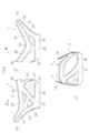
- FIG. 6A is a perspective view of the right foot seen from one obliquely rearward angle
- FIG. 6B is a perspective view of the right foot and the skeleton seen from another obliquely rearward angle
- 6C and 6D are perspective views of the right foot as seen obliquely from the front.
- Ankle foot towards the outer ankle A L of the outer leg side of the inner malleolus A M of the inner foot side is positioned below.
- the inner leg side of the heel shown in FIG. 6 (b) include projections called calcaneal No ⁇ projections A B, there are some overhanging portion F1 on the inner leg side of FIG. 6 (a).
- the outer leg side of the heel of FIGS. 6 (a) at diagonally behind the outer ankle A L, there is a constricted portion F2 was Batch (neck) between the outer ankle A L and foot. From the sole to the constricted portion F2, the outer foot side of the heel tapers upward.
- the shoe according to the present invention includes, in the first aspect, an upper 2 in which an upper edge of the shoe opening 20 is defined by an inner foot line 21 and an outer foot line 22, and a counter 1.
- the upper edge of the counter 1 is defined by a first counter line 11 on the inner foot side and a second counter line 12 on the outer foot side that are convex toward the lower side D at a position below the upper edge of the shoe opening 20. ..
- the inner foot height difference H M is defined by the difference in the height direction between the lowermost first point O1 on the inner foot line 21 and the lowermost second point O2 on the first counter line 11.
- the outer foot height difference H L is defined by the difference in the height direction between the lowermost third point O3 on the outer foot line 22 and the lowermost fourth point O4 on the second counter line 12.
- the outer foot height difference H L is larger than the inner foot height difference H M.
- the outer foot height difference H L is larger than the inner foot height difference H M , and therefore, the second foot counter line 12 on the outer foot side is lower than the first counter line 11 on the inner foot side. Will be placed in.
- the counter on the outer foot side, in which the second counter line 12 is arranged on the lower side easily comes into contact with a portion below the constricted portion F2 on the outer foot side, and the upper is fitted to the outer foot side of the heel. Will make it easier.
- the inner foot line and the outer foot line mean lines on the inner foot side and the outer foot side of the top line that defines the mouthpiece 20, and both are connected to each other on the rear end side of the upper.
- the inner foot side and the outer foot side respectively mean the portions that cover the inner foot and the outer foot of the foot and are visually recognized in the inner and outer side views of the upper.
- the first counter line 11 and the second counter line 12 that define the upper edge of the counter mean a line in which the uppermost points in the cross section of the inner and outer counters are connected to the front and back. Therefore, there is a counter portion directly below each counter line, and no counter portion directly above each counter line.
- the shoe according to the present invention includes an upper 2, a sole joined to the upper 2, and a counter 1.
- the upper 2 has an inner foot line 21 and an outer foot line 22 that define the upper edge of the shoe opening 20 and are convex toward the lower side D on the inner foot side and the outer foot side, respectively.
- the counter 1 has a heel portion 15 that extends upward from the sole 4 at a lower position of a rear portion of the shoe opening 20 and is arranged on the inner foot side, the back side, and the outer foot side of the upper 2.
- the counter 1 is a movable portion on the inner foot side and the outer foot side that extends obliquely forward and upward from the heel portion 15 at a position below the front portion of the shoe opening 20 on the inner foot side and the outer foot side, respectively.
- the upper edge of the counter 1 is a first counter line 11 and a second counter line 12 which are convex toward the lower side D along the inner foot line 21 and the outer foot line 22 on the inner foot side and the outer foot side, respectively. Is defined.
- the inner foot height difference H M is defined by the difference in the height direction between the lowermost first point O1 on the inner foot line 21 and the lowermost second point O2 on the first counter line 11.
- the outer foot height difference H L is defined by the difference in the height direction between the lowermost third point O3 on the outer foot line 22 and the lowermost fourth point O4 on the second counter line 12.
- the lowermost third point O3 is disposed below the lowermost first point O1 by D.
- the outer foot height difference H L is larger than the inner foot height difference H M.
- the heel part will help the state of grasping the heel with the upper, and will exhibit the above-mentioned stability performance and the above-mentioned hold function.
- the movable parts that extend diagonally forward and upward from the heel part will be pulled closer to each other along the sides of the foot due to shoe laces, etc., which will improve the foot's upper foot by the counter.
- a general adult man has the outer ankle located 7 mm or more below the inner ankle and 12 mm or more behind the inner ankle.
- the third point O3 is arranged below the first point O1 by D, so that the outer foot line 22 can be prevented from interfering with the outer ankle located at a position lower than the inner ankle.
- the inner foot height difference H M is smaller than the outer foot height difference H L , the function of supporting the side surface of the foot of the counter 1 on the inner foot side is larger than that on the outer foot side. Therefore, the function of suppressing the pronation in which the foot falls inward will be enhanced.
- the fourth point O4 of the counter is arranged further below the third point O3 arranged below the first point O1. Will be done. Therefore, the height from the outer ankle to the second counter line 12 on the outer foot side becomes large. Therefore, the counter does not face the bulge of the outer ankle, and therefore, the counter is more likely to come into contact with a portion below the constricted portion F2 on the outer foot side of the lower position of the outer ankle. As a result, on the outer foot side, the foot of the counter 1 will be even better.
- the inside and the outside are formed to have substantially the same shape and size. Therefore, when the known counter is applied to sports shoes, the inner foot height difference H M becomes large and the outer foot height difference H L becomes small. With such a structure, on the inner foot side, the portion supported by the counter 1 is insufficient, and it may not be possible to sufficiently suppress the foot from falling to the inner foot side. On the outer foot side, the second counter line 12 may be too close to the outer ankle, and the foot of the counter 1 may not be along the foot.
- the shoe according to the present invention comprises, in the third aspect, an upper 2 defining a mouth opening 20 and a counter 1.
- the upper edge of the counter 1 is defined by a first counter line 11 on the inner foot side and a second counter line 12 on the outer foot side that are convex toward the lower side D at a position below the upper edge of the shoe opening 20. ..
- the lowermost fourth point O4 on the second counter line 12 is disposed below the lowermost second point O2 on the first counter line 11.
- the fourth point O4 is arranged at a position within 15% from the rear end 24 of the inside of the upper 2 with respect to the entire length of the insole 7 accommodated in the upper.
- the lowermost fourth point O4 of the counter line 12 on the outer foot side is located within 15% from the rear end, so that when the foot is inserted into the shoe, the fourth point O4 is positioned more than the ankle. Located behind. Therefore, the part of the upper located posterior to the ankle will be more likely to follow the foot on the outer foot side.
- FIG. 1(a) and 1(b) are respectively an inner side view and an outer side view of a shoe showing a first embodiment of the present invention
- FIG. 1(c) is a partial longitudinal sectional view of the shoe showing an insole.
- the dot pattern is attached to the counter in FIG. 2(a) and 2(b) are an inner side view and an outer side view, respectively, showing the rear foot portion of the shoe.
- 3(a) and 3(b) are an inner side view and an outer side view, respectively, showing the rear foot portion of the shoe.
- 4(a) and 4(b) are an inner side view and an outer side view, respectively, showing the rear foot portion of the shoe.
- 5A, 5B and 5C are an inner side view, an outer side view and a rear view showing the counter, respectively.
- 6(a) and 6(b) are perspective views of the foot as viewed from different angles obliquely rearward, respectively, and FIGS. 6(c) and 6(d) are respectively different angles obliquely forward as the foot is respectively illustrated. It is a perspective view of the foot seen from. 7(a) and 7(b) are an inner side view and an outer side view, respectively, showing the rear foot portion of the shoe of the second embodiment.
- 8A and 8B are an inner side view and an outer side view, respectively, showing a rear foot portion of the shoe of the third embodiment.
- FIGS. 10A and 10B are an inner side view and an outer side view of the shoe of the fourth embodiment, respectively.
- FIGS. 10A and 10B are an inner side view and an outer side view of the shoe of the fifth embodiment, respectively.
- 11A and 11B are an inner side view and an outer side view of the shoe of the sixth embodiment, respectively.
- Implementations of the disclosure may include one or more of the following optional features.
- the third point O3 is disposed below the first point 01.
- the first height difference H1 is defined by the difference in the height direction from the uppermost point O on the rear end side on the inner foot line 21 to the first point O1.
- the second height difference H2 is defined by the difference in the height direction from the fifth point O5 at the rear end of the first counter line 11 and the second counter line 12 to the second point O2.
- a third height difference H3 is defined by a difference in the height direction from the fifth point O5 to the fourth point O4 on the outer foot side. This example satisfies the following formula (100). H3>H1>H2 (100)
- the size S of the shoe in the front-rear direction means the size of the wearer's foot displayed on the shoes or tags to be sold.
- the fourth point O4 of the counter 1 is arranged behind the third point O3 of the upper 2 in the front and rear direction B of the shoe.
- the first distance D M is defined by the distance in the front-rear direction from the first point O1 to the second point O2.
- the second distance D L is defined by the distance in the front-rear direction from the third point O3 to the fourth point O4. In this example, the second distance D L is larger than the first distance D M.
- the counter 1 is defined by an inner front end line 13 extending obliquely forward and upward from an inner foot lower end point O6 which is the frontmost end of the counter 1 at the upper edge of the sole on the inner foot side. .. Further, the counter 1 is defined by an outer front end line 14 extending obliquely forward and upward from an outer foot lower end point O7 which is the frontmost end of the counter 1 at the upper edge of the sole on the outer foot side.
- the lower end point O7 of the outer foot is arranged rearward B in the front-rear direction of the shoe rather than the lower end point O6 of the inner foot.
- the first width W M is defined by the distance from the second point O2 on the inner foot side to the lower end point O6 of the inner foot.
- the second width W L is defined by the distance from the fourth point O4 on the outer foot side to the outer foot lower end point O7.
- the first width W M is larger than the second width W L.
- the counter 1 further comprises a sole joined to the upper 2.
- the counter 1 has a heel portion 15 that extends upward from the sole at a lower position of a rear portion of the shoe opening 20 and is arranged on the inner foot side, the back side, and the outer foot side of the upper 2. ..
- the counter 1 is a movable part on the inner foot side and an outer foot side that extends obliquely forward and upward from the heel portion 15 at a position below the front part of the shoe opening 20 on the inner foot side and the outer foot side, respectively.
- the back side of the upper includes at least the rearmost end portion of the upper, and includes the rear end portions of the inner foot side and the outer foot side, but the boundary with the inner and outer foot sides does not matter.
- the fourth point O4 is located rearward B of the shoe in the front-rear direction with respect to the second point O2.
- the shoe further includes shoelaces 5 that draw the inner foot 2M and the outer foot 2L of the upper 2 together.
- the inner foot portion 2M and the outer foot portion 2L define a plurality of eyelets H with which the shoe laces are engaged.
- the movable parts 16 on the inner foot side and the outer foot side extend toward the rearmost eyelet H N of the eyelets of the inner foot portion 2M and the outer foot portion 2L, respectively.
- the first length L M is defined by the length in the front-rear direction from the second point O2 to the tip of the movable portion 16 on the inner foot side.
- the second length L L is defined by the length in the front-rear direction from the fourth point O4 to the tip of the movable portion 16 on the outer foot side. In this example, the second length L L is longer than the first length L M.
- (Embodiment 1) 1 to 5 show the first embodiment.
- the present athletic shoe includes an upper 2, a sole 4, and a counter 1.
- the upper 1 may be provided with a cushion material made of resin foam between the outer upper material (outer skin) and the waist lining material (inner skin).
- a well-known insole may be sewn to the upper 2.
- the upper 2 of FIG. 2 has legs extending upward and a shoe opening 20 for inserting a foot.
- An insole 7 shown in FIG. 1C is arranged on the insole in the upper 2.
- the upper 2 is provided with a fastener such as a shoelace 5.
- the shoe lace 5 draws the inner foot portion 2M and the outer foot portion 2L toward each other so that the inner foot portion 2M and the outer foot portion 2L of the upper 2 come into close contact with the foot and tightens the upper 2.
- the inner foot portion 2M and the outer foot portion 2L define a plurality of eyelets H with which the shoe lace 5 engages.
- Reference numeral 6 is a tongue provided in front of the shoe opening 20.
- the inner foot portion 2M of the upper 2 covers the inner foot surface of the foot.
- the outer foot portion 2L of the upper 2 covers the outer foot surface of the foot.
- the inner foot portion 2M and the outer foot portion 2L of the upper 2 are connected to each other on the back side 2B of the upper 2.
- the outer ankle A L and Uchikurubushi A M, respectively, are exposed above the Shaft 20.
- the counter 1 is adhered and fixed to the outer surface of the upper 2 at the inner foot portion 2M and the outer foot portion 2L of the upper 2.
- the upper 2 having the counter 1 bonded to the outer surface thereof has a high bending rigidity, and easily contributes to the suppression of valgus (falling of the foot toward the inner foot).
- the counter 1 is integrally formed of, for example, a non-foamed material containing a thermoplastic resin component.
- the counter 1 may be made of other material such as artificial leather.
- a sole 4 is laminated below the counter 1 and the insole.
- FIG. 1 a dot pattern is attached to the counter 1 for the sake of explanation.
- the counter 1 shown in FIGS. 1 to 4 is adhered to the outer surface of the cloth forming the upper 2, and retains the heel portion 23 of the flexible upper 2 formed of a plurality of layers of cloth.
- the inner foot side arranged on the inner foot portion 2M and the outer foot side arranged on the outer foot portion 2L are integrally formed as shown in FIG. 5(c).
- the counter 1 has a frame shape (loop shape) formed by an inner foot beam 34, an outer foot beam 35, an inner foot arm 36, an outer foot arm 37, an inner foot base 38, and an outer foot base 39 on each of the inner foot side and the outer foot side. Is formed in.
- the frame-shaped counter 1 is provided with a plurality of through holes 19 (FIG. 1). A sheet-shaped resin or the like may be attached to the portion of the through hole 19 to protect the heel portion 23.
- the inner foot beam 34 and the outer foot beam 35 extend downward in a convex band shape inside and outside (inner foot side and outer foot side), respectively.
- the inner foot base 38 and the outer foot base 39 extend in the front-rear direction of the shoe, with some of the inner foot base 38 and the outer foot base 39 being sandwiched between the upper 2 and the winding portion 40 of the sole 4.
- the inner foot beam 34 and the outer foot beam 35 of FIG. 5 are arranged at the top of the counter 1 and are connected to each other on the back side.
- the inner foot base 38 and the outer foot base 39 are connected to each other on the back side.
- the inner foot beam 34 and the inner foot base 38 are connected to each other by the first and second bridges 31 and 32.
- the inner foot beam 34 and the outer foot base 39 are connected to each other by a third bridge 33 on the back side.
- the outer foot beam 35 and the outer foot base 39 are connected to each other by the fourth bridge 34B.
- the first bridge 31 and the fourth bridge 34B are formed thinner than the second bridge.
- the counter 1 of FIG. 2 has a heel portion 15 and a movable portion 16.
- the heel portion 15 extends upward from the sole 4 at a position D below the rear portion of the shoe opening 20 and is arranged on the inner foot side, the back side, and the outer foot side of the upper 2.
- the movable portion 16 extends obliquely forward and upward from the heel portion 15 at a position D below the front portion of the shoe opening 20 on the inner foot side and the outer foot side.
- Eyelet pieces 8 are provided on the two rear end eyelets including the eyelets H N.
- the eyelet piece 8 is formed in an oval shape, and is arranged in an oblique direction such that the extending direction of the movable portion 16 and the extending direction of the long axis of the eyelet piece 8 are aligned.
- the shoe opening 20 of the upper 2 is defined by an inner foot line 21 on the inner foot side and an outer foot line 22 on the outer foot side.
- both the inner foot line 21 and the outer foot line 22 are formed by downwardly convex lines, and each has a first point O1 and a third point O3 at the lowest end on the line.
- the inner foot line 21 and the outer foot line 22 are not limited to be convex downward, and may be linear or curved with an inclination in the front-rear direction, or may be linear without an inclination. ..
- the third point O3 on the outer foot side is arranged below the first point O1 on the inner foot side.
- the upper edge of the counter 1 in FIG. 2 is defined by a first counter line 11 on the inner foot side and a second counter line 12 on the outer foot side.
- the first counter line 11 and the second counter line 12 are lines at the upper edges of the inner foot beam 34 and the outer foot beam 35, respectively, which are arranged above the counter.
- the first counter line 11 in FIG. 2 is a line that is convex downward along the inner foot line 21 of the upper.
- the second counter line 12 is a line that is convex downward along the outer foot line 22 of the upper.
- the slope of the first counter line 11 from the rear end to the front is formed more gently than the slope of the second counter line 12 from the rear end to the front.
- the second counter line 12 is curved more downward than the first counter line 11. Further, the second counter line 12 has a portion including a smaller radius of curvature than the first counter line 11.
- the first counter line 11 and the second counter line 12 in FIG. 2 have a second point O2 and a fourth point O4, which are the lowest points on the line, respectively. Therefore, the first counter line 11 and the second counter line 12 extend diagonally forward and forward in front of the second point O2 and the fourth point O4, respectively, while extending more than the second point O2 and the fourth point O4. At the rear, it extends obliquely upward and rearward.
- the distance between the inner foot line 21 and the first counter line 11 is substantially constant, but the distance between the outer foot line 22 and the second counter line 12 is different before and after the fourth point O4.
- the distance between the fourth point O4 and the rear end of the second counter line 12 is greater than the distance between the front end of the second counter line 12 and the fourth point O4. large. As a result, the region where the upper is exposed without being covered by the counter becomes larger behind the fourth point O4.
- the inner foot height difference H M and the outer foot height difference H L shown in FIGS. 3A and 3B are defined as follows.
- Inner foot height difference H M the difference in the height direction between the lowermost first point O1 on the inner foot line 21 and the lowermost second point O2 on the first counter line 11.
- Outer foot height difference H L The difference in the height direction between the lowermost third point O3 on the outer foot line 22 and the lowermost fourth point O4 on the second counter line 12.
- the inner foot height difference H M and the outer foot height difference H L are also the heights of the regions where the upper is exposed without being covered by the counter in each of the inside and outside.
- the outer leg height difference H L is larger than the inner foot height difference H M. Therefore, the second counter line 12 on the outer foot side is arranged at a position lower than the first counter line 11 on the inner foot side by lowering.
- the first height difference H1, the second height difference H2, and the third height difference H3 in FIG. 3 are defined as follows.
- First height difference H1 difference in height direction from the highest point O on the rear end side on the inner foot line 21 to the first point O1.
- Second height difference H2 difference in the height direction from the fifth point O5 to the second point O2 at the rear end of the first counter line 11 and the second counter line 12 on the inner foot side.
- Third height difference H3 difference in the height direction from the fifth point O5 to the fourth point O4 on the outer foot side.
- the first to third height differences H1 to H3 satisfy the following formula (100). H3>H1>H2 (100)
- the second height difference H2 of the heel portion 15 of the first counter line 11 is smaller than the first height difference H1 of the heel portion of the upper 2. Therefore, the second point O2 on the first counter line 11 is arranged at a position near the first point O1 on the inner leg line 21.
- the third height difference H3 of the heel portion 15 of the second counter line 12 is larger than the first height difference H1 on the inner foot side in FIG. 3(a). Therefore, the fourth point O4 on the second counter line 12 is arranged at a position apart from the third point O3 on the outer foot line 22.
- S / 100 ⁇ H L -H M ⁇ S / 10 > (110)
- the value obtained by subtracting the inner leg height difference H M from the outer leg height difference H L (H L -H M) may be set to about 1.0 cm. If the difference between the outer foot height difference H L and the inner foot height difference H M is too small, there may be cases where the above-mentioned functions are not sufficiently improved.
- the outer foot height difference H L may preferably satisfy the following formula (120) with respect to the size S. S/27 ⁇ HL ⁇ S/6 (120) For example, when the shoe size S is 27 cm, the outer foot height difference H L may be set to 1.0 to 4.5 cm.
- the reason for setting such a range is that if the outer foot height difference H L is too large, the original function of the counter is deteriorated. On the other hand, if the outer foot height difference H L is too small, along the upper foot of the counter part. This is because it is difficult to obtain the improvement effect.
- the fourth point O4 of the counter 1 is arranged behind the third point O3 of the upper 2 in the front-back direction B of the shoe.
- the second point O2 of the counter 1 is arranged at a position substantially directly below the first point O1 of the upper 2.
- the fourth point O4 is located behind the second point O2.
- the fourth point O4 is located rear B with respect to the center of the entire length of the counter 1 in the front-rear direction.
- the second point O2 may be located in front F with respect to the center of the entire length of the counter 1 in the front-rear direction.
- the second distance D L in FIG. 2 is larger than the first distance D M.
- the first distance D M and the second distance D L are defined as follows.
- First distance D M Distance in the front-rear direction (horizontal direction) from the first point O1 to the second point O2.
- Second distance D L Distance in the front-rear direction (horizontal direction) from the third point O3 to the fourth point O4.
- the inner leg arm 36 and the outer leg arm 37 of the counter 1 define an inner front end line 13 and an outer front end line 14, respectively.
- the inner front end line 13 extends obliquely forward and upward from a lower end point O6 of the inner foot which is the frontmost end of the counter 1 at the upper edge of the sole on the inner foot side.
- the outer front end line 14 extends obliquely forward and upward from the outer foot lower end point O7, which is the frontmost end of the counter 1 at the upper edge of the sole on the outer foot side.
- the inner front end line 13 and the outer front end line 14 are each formed in a curved shape having a gentle convex shape toward the rear. Note that these points O6 and O7 are the intersections of the front end lines and the upper edge of the winding portion 40 of the sole 4.
- the lower end point O7 of the outer foot is arranged rearward B in the front-rear direction of the shoe than the lower end point O6 of the inner foot.
- the inner leg arm 36 extends obliquely upward from the front end of the inner leg base 38 so as to connect to the front end of the inner leg beam 34.
- the outer foot arm 37 extends obliquely upward from the front end of the outer foot base 39 so as to connect to the front end of the outer foot beam 35. That is, the arm and the beam of each of the inner foot portion and the outer foot portion are connected to each other at the front end portion, and the angle between them is an acute angle. As a result, the region surrounded by the upper edge line of the counter (beam) and the front end line of the arm is formed so that the width becomes narrower toward the front.
- the first width W M which is the base end portion of the inner foot movable portion 16 in FIG. 4A
- the second width W M which is the base end portion of the outer foot movable portion 16 in FIG. 4B.
- width W L the widths W M and W L are defined as follows. First width W M : Distance from the second point O2 on the inner foot side to the lower end point O6 of the inner foot. Second width W L : Distance from the fourth point O4 on the outer foot side to the lower end point O7 of the outer foot.
- each length L M , L L is defined as follows.
- First length L M length in the front-rear direction from the second point O2 to the tip of the movable portion 16 on the inner foot side.
- Second length L L The length in the front-rear direction from the fourth point O4 to the tip of the movable portion 16 on the outer foot side.
- the fourth point O4 on the outer foot side of FIG. 1(c) is preferably the rear end of the inside of the upper 2 (the rear end of the insole arranged inside the shoe).
- the length L4 in the front-rear direction from the corresponding position 24 to the fourth point O4 is arranged at a position within 15% of the total length. More preferably, it may be arranged at a position of 5% to 15%.
- the total length of the inner size of the insole or the shoe can be substituted.
- the lowermost third point O3 on the outer foot line 22 is arranged below the lowermost first point O1 on the inner foot line 21. Is preferred. By arranging the first point O1 and the third point O3 in this way, it is possible to prevent the outer foot line 22 from interfering with the outer ankle located at a position lower than the inner ankle.
- the fourth point O4 of the counter is arranged further below the third point O3 arranged below the first point O1. Therefore, the height from the outer ankle to the second counter line 12 on the outer foot side becomes large. Further, the second counter line has a downwardly convex shape so as to cover the periphery of the outer ankle. Therefore, on the outer foot side, the counter will easily follow the outer foot surface of the heel that is tapered and slender upward. Further, the height of the region where the upper is exposed without being covered by the counter is large. As a result, the fit of the upper on the outer foot side will be improved.
- the heel portion 15 is interposed via the movable portion 16 that is pulled toward the shoe lace 5. It is easy to follow the lower side surface of the constricted portion F2 of the outer foot. Therefore, the foot along the upper will be improved.
- the second point O2 of the counter is arranged at a position close to the first point O1 arranged above the third point O3 in FIG. Therefore, the height from the inner ankle to the first counter line 11 on the inner foot side becomes small. Therefore, such a counter covers the inner foot calcaneal No ⁇ projections A overhanging the side B, it would be highly function of suppressing pronation to fall on the foot inner foot side.
- the foot in the inner foot portion 2M in which the first counter line 11 of FIG. 3 is arranged at a high position, the foot is moved to the inner foot side by the movable portion 16 and the heel portion 15 that are pulled toward the shoe laces 5. It is easy to suppress falling down.
- the second height difference H2 on the inner foot side of the counter is smaller than the first height difference H1 of the upper. Therefore, on the inner foot side, the first counter line 11 can be brought close to the first point O1 at the lowermost end of the inner foot line 21 of the upper. Therefore, it will be easier to further suppress the pronation where the foot falls to the inner foot side.
- the third height difference H3 on the outer foot side of the counter is larger than the first height difference H1 of the upper. Therefore, on the outer foot side, the second counter line 12 can be kept away from the third point O3 at the lowermost end of the outer foot line 22 of the upper.
- the fourth point O4 on the second counter line 12 is arranged at a position apart from the third point O3 on the outer foot line 22. Therefore, the counter easily follows the outer surface of the heel below the constricted portion F2 on the outer foot side.
- the fourth point O4 is located behind the third point O3. Further, the second distance D L is larger than the first distance D M. Therefore, the foot along the upper on the outer foot side will be further improved.
- the counter 1 has front end lines extending diagonally forward and upward.
- each base 38 of the counter 1 is formed. , 39, and the upper is easily pulled up by shoe laces.
- the feet of the counter will be improved and the above-mentioned functions of the counter will be improved.
- the inner front end line 13 and the outer front end line 14 are each formed in a curved shape having a gentle convex shape toward the rear, local deformation of each arm 36, 37 when the shoe is worn. It's unlikely to happen.
- the base portion that supports the counter on the inner foot side becomes longer, and the counter moves to the inner foot. It is easy to suppress falling to the side. Further, if a part of the base portion is sandwiched between the upper 2 and the winding portion 40 of the sole 4, the collapse of the inner foot side can be suppressed more effectively. Therefore, the function of suppressing pronation will be further enhanced.
- the base portion supporting the counter on the outer foot side becomes shorter. Therefore, the counter easily follows the foot on the outer foot side. Therefore, the feet along the upper will be further increased.
- the first width W M is larger than the second width W L. Therefore, the counter portion (movable portion 16) extending obliquely forward and upward along the front end lines 13 and 14 is movable on the inner foot side from the second point O2 to the sixth point O6 as a base end, On the other hand, on the outer foot side, it is movable with the fourth point O4 to the seventh point O7 as the base end.
- the first width W M on the inner foot side is larger than the second width W L on the outer foot side, and the movable portion 16 on the inner foot side is difficult to move. Therefore, when the foot tries to fall to the inner foot side, the fall of the foot may be easily suppressed.
- the heel portion 15 of the first width W M is larger inner foot side in FIG. 4 (a), supporting the inner leg to above, it would be easy to suppress the inclination of the foot to the inner foot side.
- the first bridge 31 and the second bridge 32 are arranged in the X shape, the deformation of the counter 1 on the inner foot side will be suppressed. In this case, if the first bridge 31 is made thinner than the second bridge 32, it will be possible to reduce the weight of the counter 1 while suppressing deformation.
- the second width W L on the outer foot side is smaller than the first width W M on the inner foot side, and the movable portion 16 on the outer foot side is easily movable. Therefore, the movable portion 16 is easily attracted by shoelaces, and the counter easily follows the foot.
- the movable portion 16 on the outer foot side having a small second width W L in FIG. 4B has a small bending rigidity, and is likely to be deformed to the center of the inside and outside of the foot as shown by the arrow in FIG. 5C. Therefore, the foot along the upper will be improved.
- the fourth bridge 34B of FIG. 2B extends from the vicinity of the fourth point O4 toward the outer foot base 39, and improves the foot along the outer foot portion while ensuring the strength near the fourth point. I'm sure In this case, if the fourth bridge 34B is formed thinner than the other bridges, the weight of the counter 1 can be reduced while ensuring the strength.
- the heel portion 15 will exhibit the above-mentioned stability performance and hold function.
- the movable part 16 will improve the upper foot along the heel. Further, the heel portion 15 and the movable portion 16 will cooperate to exert the function of suppressing pronation.
- the inner and outer movable parts 16 extending toward the rearmost eyelet are attracted to the shoe laces 5 so that the upper can follow the foot in front of the ankle. Let's do it.
- the direction in which the movable portion 16 extends and the direction in which the major axis of the eyelet piece 8 extends are along the legs of the movable portion inside and outside of the foot will be further improved.
- each movable part 16 in FIG. 4 is larger than the first length L M , the outer foot-side movable part 16 is larger than the inner foot-side movable part 16. It is also long in the diagonal direction.
- the movable part 16 on the outer foot side is easy to follow the shape of the outer foot in combination with the small bending rigidity as described above, and will further improve the foot along the upper foot on the outer foot side.
- the fourth point O4 is set from the rear end of the length of the insole in a position within 15% from the rear end of the outer ankle A L of the foot inserted in the shoe
- the 4th point O4 will be located in the back B, and the leg
- FIG. 7 shows the second embodiment. Note that, here, the points different from the first embodiment will be mainly described, and the description of the overlapping points will not be repeated.
- the lowermost second point O2 and the fourth point O4 on the counter lines 11 and 12 are represented by lines.
- the value of the second height difference H2 (FIG. 3) is zero.
- the first counter line 11 that is, the upper edge of the inner foot beam 34 is at the same height from the second point O2 to the rear end fifth point O5.
- the upper edge of the outer foot beam 35 of the second counter line 12 has the same height between the two fourth points O4 and O4.
- the position in the front-rear direction of the second point O2 in FIG. 7A may be understood to be any position from the second point O2 to the fifth point O5 shown in FIG.
- the position of the fourth point O4 in the front-rear direction in FIG. 7B is understood to be any position from one fourth point O4 to another fourth point O4 shown in FIG. However, it is preferable to understand that it is the most forward position in the second counter line 12. The reason is that the fourth point O4 is arranged at a lower position on the outer foot side, and this counter aims to improve the foot along the upper rear end portion on the outer foot side. In the present embodiment, since the range of the lowest points of the first and second counter lines 11 and 12 can be widened, it is possible to provide shoes corresponding to various users having different heel positions.
- the third height difference H3 in FIG. 7B is smaller than the first height difference H1 in FIG. 7A.
- FIG. 8 shows the third embodiment.
- the heel portion 15 of the counter 1 is built in the upper 2, and the exterior counter 1 in which the movable portion 16 of the counter 1 and the like are formed is provided.
- the upper edge line of the exterior counter 1 is provided in an inclined shape so that the height becomes lower from the front to the rear.
- the built-in counter 1A forming the heel portion 15 is formed in a hemispherical shape in rear view so as to descend from the fifth point O5 at the rear end toward the front.
- the second point O2 in FIG. 8A is defined by the intersection of the built-in counter 1A and the exterior counter 1M on the inner foot side.
- the fourth point O4 in FIG. 8B is defined by the intersection of the built-in counter 1A and the outer foot side exterior counter 1L.
- the exterior counter and the built-in counter may be combined in opposite shapes, and both members may be exteriorly packaged in the upper. In this embodiment, the shape of the counter can be simplified.
- FIG. 9 shows the fourth embodiment.
- the points different from the first to third embodiments will be mainly described, and the description of the overlapping points will not be repeated.
- the outer foot base 39 is shorter in the front-rear direction than in each of the above-described embodiments.
- the outer foot base 39 may not be provided.
- the front end lines 13 and 14 of the inner leg and outer leg arms 36 and 37 may linearly extend obliquely in the front-rear direction.
- the first bridge 31 may be vertically installed between the inner foot beam 34 and the inner foot base 38.
- the first bridge 31 may be formed thinner than the inner foot beam 34 and the inner foot base 38.
- the fourth bridge 34B may be vertically installed between the outer foot arm 35 and the outer foot base 39.
- the fourth bridge 34B may be formed to have the same thickness as the outer leg arm 35 and the outer leg base 39. Note that each through hole 19 may not be provided.
- the strength of the heel portion 15 can be set to be weaker than that in the other embodiments, so that the cushioning property at the time of landing can be imparted to the shoe.
- FIG. 10 shows the fifth embodiment.
- the counter 1 has the same shape and structure on the inner foot side and the outer foot side, except that the inner foot beam 34 and the outer foot beam 35 have different shapes.
- the present embodiment can be applied to a shoe or the like having an upper that is stronger than the other embodiments.
- the inner and outer through holes 19 may be formed so as to be continuous on the back side. This is because the upper itself has strength.
- the movable portion 16 is shorter than the movable portion of each of the above-described embodiments. Furthermore, if each of the counter lines 11 and 12 is convex downward, the movable part 16 may not be provided. Further, the sixth point O6 and the seventh point O7 may be at the same position in the front-rear direction. In the present embodiment, the cushioning property at the time of landing can be imparted to the shoe more than in the fourth embodiment.
- FIG. 11 shows the sixth embodiment.
- the upper 2 is a middle-cut or high-cut type
- the inner foot portion 2M covers the inner ankle
- the outer portion 2L covers the outer ankle.
- the inner foot line 21 and the outer foot line 22 extend in the horizontal direction. Therefore, the first point O1 and the third point O3 may be set at any points on the lines 21 and 22.
- the first point O1 of the inner foot line 21 and the third point O3 of the outer foot line 22 may be set at the same height, or one of them may be set higher than the other. May be. According to the present embodiment, an effect similar to that of the other embodiments can be obtained even in a middle-cut or high-cut type shoe.
- the counter 1 is externally mounted on the upper 2 in the above-described first, second, and fourth to sixth embodiments
- the counter may be built in the upper.
- the counter may be arranged between the outer shell material (exterior material) and the waist lining material (interior material) of the upper.
- the counter may be divided into two parts on the inner foot side and the outer foot side at the rear end of the upper.
- the counter 1 may be divided into three, a built-in counter 1A, an exterior counter 1M, and an exterior counter 1L.
- the divided counters may be made of different materials. There may be a gap in the width direction of the foot between the counters divided into the inside and the outside at the heel center.
- the counter of FIG. 2 may have a shape having only the arms 36 and 37 and the beams 34 and 35 without providing the bases 38 and 39 and/or the bridges 31 to 33 and 34B.
- each arm and each beam may not be integrally formed with each other seamlessly, but may have some breaks between the beams 34 and 35 and the movable portions 16 and 16.
- the movable part 16 may be formed thinner than the other parts of the counter.
- the length of the movable portion may be the same on the inner foot side and the outer foot side, or may be different.
- Portions other than the first counter line 11 and the second counter line 12 may have symmetrical shapes on the inner and outer foot sides.
- the eyelet H N at the rearmost end may be formed integrally with the movable portion 16.
- the sole arranged below the upper may have a so-called outsole and/or midsole.
- the counter When the counter is of a built-in type, the counter may be a cardboard or a paperboard impregnated with the resin, in addition to the thermo
- the counter can stably support and hold the inner foot and the outer foot. Also, the counter on the inner foot side will suppress the fall of the inner foot, and the function of suppressing the pronation will be enhanced. In addition, a counter on the outer foot side will allow the upper to easily follow the outer foot, improving the foot's alignment with the heel.
- the present invention can be applied to sports shoes for running, etc., as well as shoes for various uses such as walking.
Abstract
Description
図6(a)は右足を斜め後方の1つの角度から見た斜視図、図6(b)は右足および骨格を斜め後方の別の角度から見た斜視図である。図6(c)および(d)はそれぞれ、右足を斜め前方から見た斜視図である。 The principle of the present invention will be described with reference to FIG.
FIG. 6A is a perspective view of the right foot seen from one obliquely rearward angle, and FIG. 6B is a perspective view of the right foot and the skeleton seen from another obliquely rearward angle. 6C and 6D are perspective views of the right foot as seen obliquely from the front.
本発明を実施するための形態において、一部の例では、前記第3点O3が前記第1点01よりも下方Dに配置されている。 Implementations of the disclosure may include one or more of the following optional features.
In some of the exemplary embodiments of the present invention, the third point O3 is disposed below the
H3>H1>H2 ……(100) In some examples, the first height difference H1 is defined by the difference in the height direction from the uppermost point O on the rear end side on the
H3>H1>H2 (100)
S/100<HL-HM<S/10 ……(110) In some examples, the following formula (110) is satisfied, where S is the size of the shoe in the front-rear direction.
S / 100 <H L -H M <S / 10 ...... (110)
図1~図5は実施形態1を示す。図1に示すように、本運動靴は、アッパー2、ソール4およびカウンタ1を備える。 (Embodiment 1)
1 to 5 show the first embodiment. As shown in FIG. 1, the present athletic shoe includes an upper 2, a sole 4, and a
カウンタ1および中底の下方には、ソール4が積層されている。 The
A sole 4 is laminated below the
図1~図4に示すカウンタ1は、アッパー2を形成する生地の外表面に接着されており、複数層の生地で形成された柔軟なアッパー2の踵部23を保形する。図1のカウンタ1は内足部2Mに配置された内足側と、外足部2Lに配置された外足側とが、図5(c)のように一体に形成されている。 Next, an example of a specific structure of the
The
内足高低差HM:内足ライン21上の最下端の第1点O1と第1カウンタライン11上の最下端の第2点O2との高さ方向の差。
外足高低差HL:外足ライン22上の最下端の第3点O3と第2カウンタライン12上の最下端の第4点O4との高さ方向の差。
なお、内足高低差HMおよび外足高低差HLは、内外のそれぞれにおいて、カウンタに覆われずにアッパーが露出する領域の高さでもある。 The inner foot height difference H M and the outer foot height difference H L shown in FIGS. 3A and 3B are defined as follows.
Inner foot height difference H M : the difference in the height direction between the lowermost first point O1 on the
Outer foot height difference H L : The difference in the height direction between the lowermost third point O3 on the
The inner foot height difference H M and the outer foot height difference H L are also the heights of the regions where the upper is exposed without being covered by the counter in each of the inside and outside.
第1高低差H1:内足ライン21上の後端側の最上点Oから第1点O1までの高さ方向の差。
第2高低差H2:内足側において、第1カウンタライン11および第2カウンタライン12における後端の第5点O5から第2点O2までの高さ方向の差。
第3高低差H3:外足側において、第5点O5から第4点O4までの高さ方向の差。 The first height difference H1, the second height difference H2, and the third height difference H3 in FIG. 3 are defined as follows.
First height difference H1: difference in height direction from the highest point O on the rear end side on the
Second height difference H2: difference in the height direction from the fifth point O5 to the second point O2 at the rear end of the
Third height difference H3: difference in the height direction from the fifth point O5 to the fourth point O4 on the outer foot side.
H3>H1>H2 ……(100) The first to third height differences H1 to H3 satisfy the following formula (100).
H3>H1>H2 (100)
S/100<HL-HM<S/10 ……(110)
例えば靴のサイズSが27cmである場合、外足高低差HLから内足高低差HMを減算した値(HL-HM)は1.0cm程度に設定されてもよい。
外足高低差HLと内足高低差HMとの差が小さすぎると、前記各機能の向上が十分でない場合が生じるかもしれない。 Inner foot height difference H M and outer leg height difference H L in FIG. 3, when the front-rear direction size of the shoe is S, satisfies the equation (110) below.
S / 100 <H L -H M <S / 10 ...... (110)
For example, if the size of the shoe S is 27cm, the value obtained by subtracting the inner leg height difference H M from the outer leg height difference H L (H L -H M) may be set to about 1.0 cm.
If the difference between the outer foot height difference H L and the inner foot height difference H M is too small, there may be cases where the above-mentioned functions are not sufficiently improved.
S/27<HL<S/6 ……(120)
例えば靴のサイズSが27cmである場合、外足高低差HLは1.0~4.5cmに設定されてもよい。 The outer foot height difference H L may preferably satisfy the following formula (120) with respect to the size S.
S/27< HL <S/6 (120)
For example, when the shoe size S is 27 cm, the outer foot height difference H L may be set to 1.0 to 4.5 cm.
第2距離DL:第3点O3から第4点O4までの前後方向(水平方向)の距離。 First distance D M : Distance in the front-rear direction (horizontal direction) from the first point O1 to the second point O2.
Second distance D L : Distance in the front-rear direction (horizontal direction) from the third point O3 to the fourth point O4.
ここで、各幅WM,WLは以下のように定義される。
第1幅WM:内足側における第2点O2から内足下端点O6までの距離。
第2幅WL:外足側における第4点O4から外足下端点O7までの距離。 In the present embodiment, the first width W M, which is the base end portion of the inner foot
Here, the widths W M and W L are defined as follows.
First width W M : Distance from the second point O2 on the inner foot side to the lower end point O6 of the inner foot.
Second width W L : Distance from the fourth point O4 on the outer foot side to the lower end point O7 of the outer foot.
ここで、各長さLM,LLは以下のように定義される。
第1長さLM:第2点O2から内足側の可動部16の先端までの前後方向の長さ。
第2長さLL:第4点O4から外足側の可動部16の先端までの前後方向の長さ。 In FIG. 4, the second length L L of the outer foot of FIG. 4( b) is longer than the first length L M of the inner foot of FIG. 4( a ).
Here, each length L M , L L is defined as follows.
First length L M : length in the front-rear direction from the second point O2 to the tip of the
Second length L L : The length in the front-rear direction from the fourth point O4 to the tip of the
走行機能を重視した運動靴では、図3に示すように、外足ライン22上の最下端の第3点O3が内足ライン21上の最下端の第1点O1よりも下方に配置されていることが好ましい。このように第1点O1と第3点O3を配置することで、内踝よりも低い位置にある外踝に対して外足ライン22が干渉しないようにすることができる。 Next, the operation of this embodiment will be described.
In an athletic shoe emphasizing the running function, as shown in FIG. 3, the lowermost third point O3 on the
図7は実施形態2を示す。なお、ここでは上記の実施形態1と異なる点について主に説明し、重複する点については説明を繰り返さない。本実施形態においては、各カウンタライン11,12上の最下端の第2点O2および第4点O4がライン状に表われている。なお、本実施形態の場合、第2高低差H2(図3)の値はゼロである。 (Embodiment 2)
FIG. 7 shows the second embodiment. Note that, here, the points different from the first embodiment will be mainly described, and the description of the overlapping points will not be repeated. In the present embodiment, the lowermost second point O2 and the fourth point O4 on the counter lines 11 and 12 are represented by lines. In the case of this embodiment, the value of the second height difference H2 (FIG. 3) is zero.
本実施形態においては、第1および第2カウンタライン11,12の最下点の範囲を広くとれるので、踵の位置が異なる様々な使用者に対応する靴を提供できる。 In the case of the present embodiment, the position of the fourth point O4 in the front-rear direction in FIG. 7B is understood to be any position from one fourth point O4 to another fourth point O4 shown in FIG. However, it is preferable to understand that it is the most forward position in the
In the present embodiment, since the range of the lowest points of the first and
図8は実施形態3を示す。なお、ここでは上記の実施形態1、2と異なる点について主に説明し、重複する点については説明を繰り返さない。本実施形態においては、カウンタ1のヒール部15がアッパー2に内蔵され、カウンタ1の可動部16等が形成された外装カウンタ1が設けられている。外装カウンタ1の上縁ラインは、前方から後方に向かうにつれて高さが低くなるように傾斜状に設けられている。
ヒール部15を構成する内蔵カウンタ1Aは、後端の第5点O5から前方に向かうにつれて下降するように背面視で半球状に形成されている。 (Embodiment 3)
FIG. 8 shows the third embodiment. Here, the points different from the first and second embodiments will be mainly described, and the description of the overlapping points will not be repeated. In this embodiment, the
The built-in
なお、外装カウンタと内蔵カウンタの形状が逆の組合せでもよく、両部材が共にアッパーに外装されていてもよい。本実施形態においては、カウンタの形状をシンプルにできる。 In the present embodiment, the second point O2 in FIG. 8A is defined by the intersection of the built-in
It should be noted that the exterior counter and the built-in counter may be combined in opposite shapes, and both members may be exteriorly packaged in the upper. In this embodiment, the shape of the counter can be simplified.
図9は実施形態4を示す。なお、ここでは上記の実施形態1~3と異なる点について主に説明し、重複する点については説明を繰り返さない。本実施形態においては、外足ベース39が前述の各実施形態に比べ前後方向に短い。なお、外足ベース39は設けられていなくてもよい。 (Embodiment 4)
FIG. 9 shows the fourth embodiment. Here, the points different from the first to third embodiments will be mainly described, and the description of the overlapping points will not be repeated. In this embodiment, the
一方、外足側において、第4ブリッジ34Bは外足アーム35と外足ベース39との間に上下に架設されていてもよい。第4ブリッジ34Bは外足アーム35および外足ベース39と同じ厚さに形成されていてもよい。
なお、各貫通孔19は設けられていなくてもよい。
本実施形態においては、ヒール部15の強度を他の実施形態より弱く設定することができるので、着地時のクッション性を靴に付与することができる。 There may be one internal bridge and one external bridge. For example, on the inner foot side, the
On the other hand, on the outer foot side, the
Note that each through
In the present embodiment, the strength of the
図10は実施形態5を示す。なお、ここでは上記の実施形態1~4と異なる点について主に説明し、重複する点については説明を繰り返さない。本実施形態においては、内足ビーム34と外足ビーム35の形状が互いに異なっている以外は、カウンタ1は内足側と外足側とが同じ形状および構造である。本実施形態は、他の実施形態よりも強度が強いアッパーを備えた靴などに適用できる。 (Embodiment 5)
FIG. 10 shows the fifth embodiment. Here, the points different from the above-described first to fourth embodiments will be mainly described, and the description of the overlapping points will not be repeated. In the present embodiment, the
また、第6点O6と第7点O7とが前後方向に同じ位置であってもよい。
本実施形態においては、実施形態4よりさらに着地時のクッション性を靴に付与することができる。 Further, the
Further, the sixth point O6 and the seventh point O7 may be at the same position in the front-rear direction.
In the present embodiment, the cushioning property at the time of landing can be imparted to the shoe more than in the fourth embodiment.
図11は実施形態6を示す。なお、ここでは上記の実施形態1~5と異なる点について主に説明し、重複する点については説明を繰り返さない。本実施形態においては、アッパー2はミドルカットないしハイカットタイプで、内足部2Mが内踝を覆い、外側部2Lが外踝を覆う。 (Embodiment 6)
FIG. 11 shows the sixth embodiment. Here, the points different from the above-described first to fifth embodiments will be mainly described, and the description of the overlapping points will not be repeated. In the present embodiment, the upper 2 is a middle-cut or high-cut type, the
アッパーの下に配置されるソールは、いわゆるアウトソールおよび/またはミッドソールを有していてもよい。
カウンタが内蔵式である場合、カウンタは熱可塑性の樹脂の他、厚板紙や板紙に樹脂が含浸されたものであってもよい。 Further, for example, the counter of FIG. 2 may have a shape having only the
The sole arranged below the upper may have a so-called outsole and/or midsole.
When the counter is of a built-in type, the counter may be a cardboard or a paperboard impregnated with the resin, in addition to the thermoplastic resin.
上記の実施形態において、個数、量などに言及したものについては、特に記載がある場合を除き、本発明の範囲は必ずしもその個数、量などに限定されない。また、実施形態において、各々の構成要素は、特に記載がある場合を除き、本発明にとって必ずしも必須のものではない。したがって、そのような変更および修正は請求の範囲から定まる本発明の範囲のものと解釈される。 As described above, the preferred embodiments have been described with reference to the drawings, but those skilled in the art will easily think of various changes and modifications within the obvious range by viewing the present specification.
In the above embodiments, the reference to the number, the amount, etc. does not necessarily limit the scope of the present invention to the number, the amount, etc., unless otherwise specified. Further, in the embodiments, each component is not necessarily essential to the present invention unless otherwise specified. Therefore, such changes and modifications are construed as being within the scope of the present invention as defined by the claims.
以上、本実施の形態によると、カウンタにより内足および外足を安定して支持すると共にホールドすることができる。
また、内足側のカウンタにより内足の倒れを抑制し、プロネーションの抑制機能が高まるだろう。
更に、外足側のカウンタにより外足にアッパーが沿い易く、踵に対するアッパーの足沿いが向上するだろう。 (Effects of the embodiment)
As described above, according to this embodiment, the counter can stably support and hold the inner foot and the outer foot.
Also, the counter on the inner foot side will suppress the fall of the inner foot, and the function of suppressing the pronation will be enhanced.
In addition, a counter on the outer foot side will allow the upper to easily follow the outer foot, improving the foot's alignment with the heel.
2:アッパー 2M:内足部 2L:外足部 2B:背側
20履き口 21:内足ライン 22:外足ライン 23:踵部 24:後端
31~33,34B:第1~第4ブリッジ 34:内足ビーム 35:外足ビーム
36:内足アーム 37:外足アーム 38:内足ベース 39:外足ベース
4:ソール 40:巻上部
5:シューレース 6:舌片 7:中敷き 8:ハトメピース
O1~O7:第1点~第7点
AB:踵骨載距突起 AM:内踝 AL:外踝 F1:部分 F2:括れ部
DM:第1距離 DL:第2距離
WM:第1幅 WL:第2幅
HM:内足高低差 HL:外足高低差
LM:第1長さ LL:第2長さ
B:後方 D:下方 F:前方
1:
36: Inner foot arm 37: Outer foot arm 38: Inner foot base 39: Outer foot base 4: Sole 40: Winding top 5: Shoe lace 6: Tongue piece 7: Insole 8: Eyelet piece O1 to O7: 1st to
Claims (15)
- 内足ライン21および外足ライン22により履き口20の上縁が定義されるアッパー2と、
前記履き口20の前記上縁の下方位置において、下方Dに向かって凸の内足側の第1カウンタライン11および外足側の第2カウンタライン12で上縁が定義されたカウンタ1とを備え、
前記内足ライン21上の最下端の第1点O1と前記第1カウンタライン11上の最下端の第2点O2との高さ方向の差で内足高低差HMが定義され、
前記外足ライン22上の最下端の第3点O3と前記第2カウンタライン12上の最下端の第4点O4との高さ方向の差で外足高低差HLが定義され、
前記外足高低差HLが前記内足高低差HMよりも大きい、靴。 An upper 2 whose upper edge is defined by an inner foot line 21 and an outer foot line 22;
A counter 1 having an upper edge defined by a first counter line 11 on the inner foot side and a second counter line 12 on the outer foot side, which are convex toward the lower side D, at a position below the upper edge of the shoe opening 20. Prepare,
An inner foot height difference H M is defined by a difference in height direction between a lowermost first point O1 on the inner foot line 21 and a lowermost second point O2 on the first counter line 11.
An outer foot height difference H L is defined by a height direction difference between a lowermost third point O3 on the outer foot line 22 and a lowermost fourth point O4 on the second counter line 12,
The shoe, wherein the outer foot height difference H L is larger than the inner foot height difference H M. - 請求項1において、
前記第3点O3が前記第1点01よりも下方Dに配置されている、靴。 In claim 1,
The shoe in which the third point O3 is disposed below the first point 01. - 請求項1もしくは2において、
前記内足ライン21上の後端側の最上点Oから前記第1点O1までの高さ方向の差で第1高低差H1が定義され、
内足側において、前記第1カウンタライン11および第2カウンタライン12における後端の第5点O5から前記第2点O2までの高さ方向の差で第2高低差H2が定義され、
外足側において、前記第5点O5から前記第4点O4までの高さ方向の差で第3高低差H3が定義され、
下記の式(100)を満たす靴
H3>H1>H2 ……(100)。 In claim 1 or 2,
The first height difference H1 is defined by the difference in the height direction from the uppermost point O on the rear end side on the inner foot line 21 to the first point O1,
On the inner foot side, the second height difference H2 is defined by the difference in the height direction from the fifth point O5 at the rear end of the first counter line 11 and the second counter line 12 to the second point O2,
On the outer foot side, the third height difference H3 is defined by the difference in the height direction from the fifth point O5 to the fourth point O4,
Shoes satisfying the following expression (100) H3>H1>H2 (100). - 請求項1~3のいずれか1項において、
靴の前後方向のサイズをSとしたとき、下記の式(110)を満たす
S/100<HL-HM<S/10 ……(110)。 In any one of claims 1 to 3,
When the front-rear direction size of the shoe and S, S / 100 satisfying the equation (110) below <H L -H M <S / 10 ...... (110). - 請求項1~4のいずれか1項において、
前記カウンタ1の前記第4点O4が、前記アッパー2の前記第3点O3よりも靴の前後方向の後方Bに配置されている、靴。 In any one of claims 1 to 4,
The shoe in which the fourth point O4 of the counter 1 is arranged more rearward B in the front-rear direction of the shoe than the third point O3 of the upper 2. - 請求項1~5のいずれか1項において、
前記第1点O1から前記第2点O2までの前後方向の距離で第1距離DMが定義され、
前記第3点O3から前記第4点O4までの前後方向の距離で第2距離DLが定義され、
前記第2距離DLが前記第1距離DMよりも大きい、靴。 In any one of claims 1 to 5,
A first distance D M is defined by a distance in the front-rear direction from the first point O1 to the second point O2,
A second distance D L is defined as a distance in the front-rear direction from the third point O3 to the fourth point O4,
The shoe, wherein the second distance D L is greater than the first distance D M. - 請求項1~6のいずれか1項において、前記カウンタ1は、
前記内足側のソール上縁における前記カウンタ1の最前端となる内足下端点O6から斜め前方の上方に向かって延びる内前端ライン13と、
前記外足側のソール上縁における前記カウンタ1の最前端となる外足下端点O7から斜め前方の上方に向かって延びる外前端ライン14とを定義する、靴。 The counter 1 according to any one of claims 1 to 6,
An inner front end line 13 extending obliquely forward and upward from a lower end point O6 of the inner foot, which is the frontmost end of the counter 1 at the upper edge of the sole on the inner foot side,
A shoe that defines an outer front end line 14 that extends obliquely forward and upward from an outer foot lower end point O7, which is the foremost end of the counter 1 at the upper edge of the outer foot side sole. - 請求項7において、前記外足下端点O7が前記内足下端点O6よりも前記靴の前後方向の後方Bに配置されている、靴。 The shoe according to claim 7, wherein the lower end point O7 of the outer foot is arranged rearward B of the lower end point O6 of the inner foot in the front-rear direction of the shoe.
- 請求項7において、
前記内足側における前記第2点O2から前記内足下端点O6までの距離で第1幅WMが定義され、
前記外足側における前記第4点O4から前記外足下端点O7までの距離で第2幅WLが定義され、前記第1幅WMが前記第2幅WLよりも大きい、靴。 In claim 7,
A first width W M is defined by a distance from the second point O2 on the inner foot side to the inner foot lower end point O6,
A shoe in which a second width W L is defined by a distance from the fourth point O4 on the outer foot side to the outer foot lower end point O7, and the first width W M is larger than the second width W L. - 請求項1~6のいずれか1項において、前記アッパー2に接合されたソール4を更に備え、前記カウンタ1は、
前記履き口20の後部の下方位置において前記ソールから上方に延び前記アッパー2の前記内足側、背側および前記外足側に配置されたヒール部15と、
前記内足側および前記外足側の前記履き口20の前部の下方位置において、各々、前記ヒール部15から斜め前方の上方に延びる内足側および外足側の可動部16とを有する、靴。 The counter 1 according to any one of claims 1 to 6, further comprising a sole 4 joined to the upper 2.
A heel portion 15 extending upward from the sole at a lower position of a rear portion of the shoe opening 20 and arranged on the inner foot side, the back side, and the outer foot side of the upper 2,
At the lower position of the front part of the shoe opening 20 on the inner foot side and the outer foot side, there are inner and outer foot side movable parts 16 extending obliquely forward and upward from the heel part 15, respectively. shoes. - 内足側および外足側において各々、履き口20の上縁を定義し、下方Dに向かって凸の内足ライン21および外足ライン22を有するアッパー2と、
前記アッパー2に接合されたソール4と、
前記履き口20の後部の下方位置において前記ソール4から上方に延びアッパー2の前記内足側、背側および前記外足側に配置されたヒール部15と、前記内足側および前記外足側の前記履き口20の前部の下方位置において、各々、前記ヒール部15から斜め前方の上方に延びる内足側および外足側の可動部16を有するカウンタ1とを備え、
前記カウンタ1の上縁は前記内足側および前記外足側において前記内足ライン21および前記外足ライン22のそれぞれに沿い下方Dに向かって凸の第1カウンタライン11および第2カウンタライン12で定義され、
前記内足ライン21上の最下端の第1点O1と前記第1カウンタライン11上の最下端の第2点O2との高さ方向の差で内足高低差HMが定義され、
前記外足ライン22上の最下端の第3点O3と前記第2カウンタライン12上の最下端の第4点O4との高さ方向の差で外足高低差HLが定義され、
前記最下端の第3点O3が前記最下端の第1点O1よりも下方Dに配置され、前記外足高低差HLが前記内足高低差HMよりも大きい、靴。 An upper 2 having an inner foot line 21 and an outer foot line 22 that define the upper edge of the mouth opening 20 on each of the inner foot side and the outer foot side and are convex toward the lower side D;
A sole 4 joined to the upper 2,
A heel portion 15 extending upward from the sole 4 at a lower position of a rear portion of the shoe opening 20 and arranged on the inner foot side, the back side, and the outer foot side of the upper 2, and the inner foot side and the outer foot side. A counter 1 having movable parts 16 on the inner foot side and the outer foot side, which extend obliquely forward and upward from the heel part 15, respectively, at a position below the front part of the shoe opening 20;
The upper edge of the counter 1 has a first counter line 11 and a second counter line 12 that are convex toward the lower side D along the inner foot line 21 and the outer foot line 22 on the inner foot side and the outer foot side, respectively. Defined by
An inner foot height difference H M is defined by a difference in height direction between a lowermost first point O1 on the inner foot line 21 and a lowermost second point O2 on the first counter line 11.
An outer foot height difference H L is defined by a height direction difference between a lowermost third point O3 on the outer foot line 22 and a lowermost fourth point O4 on the second counter line 12,
The shoe in which the lowermost third point O3 is disposed below the lowermost first point O1 and the outer foot height difference H L is larger than the inner foot height difference H M. - 請求項11において、
前記第4点O4が前記第2点O2よりも後方Bに配置されている、靴。 In claim 11,
The shoe in which the fourth point O4 is arranged rearward of the second point O2. - 請求項10もしくは11において、
前記靴は、前記アッパー2の内足部2Mと外足部2Lとを互いに引き寄せるシューレース5を更に備え、
前記内足部2Mおよび外足部2Lは、前記シューレースが係合する複数のハトメHを定義し、
前記内足側および外足側の可動部16は、前記内足部2Mおよび外足部2Lのハトメのうち、各々、最後端のハトメHNに向かって延びている、靴。 In Claim 10 or 11,
The shoe further includes shoe laces 5 that draw the inner foot portion 2M and the outer foot portion 2L of the upper 2 toward each other,
The inner foot portion 2M and the outer foot portion 2L define a plurality of eyelets H with which the shoe laces are engaged,
The shoe in which the movable portions 16 on the inner foot side and the outer foot side extend toward the rearmost eyelet H N of the eyelets of the inner foot portion 2M and the outer foot portion 2L, respectively. - 請求項10もしくは11において、
前記第2点O2から前記内足側の前記可動部16の先端までの前後方向の長さで第1長さLMが定義され、
前記第4点O4から前記外足側の前記可動部16の先端までの前後方向の長さで第2長さLLが定義され、前記第2長さLLが前記第1長さLMよりも長い、靴。 In Claim 10 or 11,
The first length L M is defined by the length in the front-rear direction from the second point O2 to the tip of the movable portion 16 on the inner foot side,
A second length L L is defined by the length in the front-rear direction from the fourth point O4 to the tip of the movable portion 16 on the outer foot side, and the second length L L is the first length L M. Longer, shoes. - 履き口20を定義するアッパー2と、
前記履き口20の上縁の下方位置において、下方Dに向かって凸の内足側の第1カウンタライン11および外足側の第2カウンタライン12で上縁が定義されたカウンタ1とを備え、
前記第2カウンタライン12上の最下端の第4点O4が前記第1カウンタライン11上の最下端の第2点O2よりも下方に配置され、
前記第4点O4が前記アッパーに収容された中敷7の全長に対して、前記アッパー2の内部の後端24から15%以内の位置に配置されている、靴。
An upper 2 that defines the mouthpiece 20,
A counter 1 having an upper edge defined by a first counter line 11 on the inner foot side and a second counter line 12 on the outer foot side, which are convex toward the lower side D, is provided below the upper edge of the shoe opening 20. ,
The lowermost fourth point O4 on the second counter line 12 is disposed below the lowermost second point O2 on the first counter line 11,
The shoe in which the fourth point O4 is arranged at a position within 15% from the rear end 24 of the inside of the upper 2 with respect to the entire length of the insole 7 accommodated in the upper.
Priority Applications (7)
| Application Number | Priority Date | Filing Date | Title |
|---|---|---|---|
| EP19911469.5A EP3799758A4 (en) | 2019-01-24 | 2019-01-24 | Shoe with counter |
| CN201980041416.9A CN112334035B (en) | 2019-01-24 | 2019-01-24 | Shoe comprising a counter |
| AU2019424137A AU2019424137A1 (en) | 2019-01-24 | 2019-01-24 | Shoe having counter |
| US17/253,345 US11490691B2 (en) | 2019-01-24 | 2019-01-24 | Shoe having counter |
| PCT/JP2019/002246 WO2020152821A1 (en) | 2019-01-24 | 2019-01-24 | Shoe with counter |
| JP2020567312A JP7203126B2 (en) | 2019-01-24 | 2019-01-24 | shoes with counter |
| JP2022179552A JP7425275B2 (en) | 2019-01-24 | 2022-11-09 | shoes with counters |
Applications Claiming Priority (1)
| Application Number | Priority Date | Filing Date | Title |
|---|---|---|---|
| PCT/JP2019/002246 WO2020152821A1 (en) | 2019-01-24 | 2019-01-24 | Shoe with counter |
Publications (1)
| Publication Number | Publication Date |
|---|---|
| WO2020152821A1 true WO2020152821A1 (en) | 2020-07-30 |
Family
ID=71736879
Family Applications (1)
| Application Number | Title | Priority Date | Filing Date |
|---|---|---|---|
| PCT/JP2019/002246 WO2020152821A1 (en) | 2019-01-24 | 2019-01-24 | Shoe with counter |
Country Status (6)
| Country | Link |
|---|---|
| US (1) | US11490691B2 (en) |
| EP (1) | EP3799758A4 (en) |
| JP (2) | JP7203126B2 (en) |
| CN (1) | CN112334035B (en) |
| AU (1) | AU2019424137A1 (en) |
| WO (1) | WO2020152821A1 (en) |
Families Citing this family (6)
| Publication number | Priority date | Publication date | Assignee | Title |
|---|---|---|---|---|
| US11497271B2 (en) * | 2020-02-05 | 2022-11-15 | Se-Ho OH | Shoes |
| US20230148709A1 (en) * | 2021-11-18 | 2023-05-18 | Acushnet Company | Asymmetrical heel pad |
| USD972284S1 (en) * | 2021-12-16 | 2022-12-13 | Nike, Inc. | Shoe |
| USD995991S1 (en) * | 2021-12-17 | 2023-08-22 | Nike, Inc. | Shoe |
| WO2023170512A1 (en) | 2022-03-07 | 2023-09-14 | Ricoh Company, Ltd. | Positioning adjusting mechanism and positioning adjusting system |
| USD997538S1 (en) * | 2022-12-06 | 2023-09-05 | Nike, Inc. | Shoe |
Citations (6)
| Publication number | Priority date | Publication date | Assignee | Title |
|---|---|---|---|---|
| JP2008132227A (en) * | 2006-11-29 | 2008-06-12 | Mizuno Corp | Upper structure of shoe |
| JP2008206629A (en) | 2007-02-26 | 2008-09-11 | Mizuno Corp | Shoes equipped with heel counter |
| US20100307025A1 (en) * | 2008-02-27 | 2010-12-09 | Ecco Sko A/S | Midsole for a shoe, in particular a running shoe |
| US8677656B2 (en) | 2008-09-30 | 2014-03-25 | Asics Corporation | Athletic shoe with heel counter for maintaining shape of heel section |
| US20160007687A1 (en) * | 2014-07-09 | 2016-01-14 | Adidas Ag | Shoe with a heel cap and/or ankle collar |
| WO2018016382A1 (en) * | 2016-07-19 | 2018-01-25 | 株式会社アシックス | Footwear |
Family Cites Families (17)
| Publication number | Priority date | Publication date | Assignee | Title |
|---|---|---|---|---|
| US2156086A (en) * | 1935-03-30 | 1939-04-25 | Hack Shoe Co | Orthopedic shoe |
| US2203157A (en) * | 1939-02-23 | 1940-06-04 | Calvin C Klaus | Shoe |
| US2403442A (en) * | 1945-01-01 | 1946-07-09 | Calvin C Klaus | Shoe |
| DE29607422U1 (en) * | 1996-04-26 | 1996-07-25 | Meindl Lukas Gmbh Co Kg | Asymmetrical heel fixation with built-in abrasion and ankle protection |
| JP3462807B2 (en) * | 1999-08-06 | 2003-11-05 | 株式会社アシックス | Hard soles |
| JP2003339406A (en) * | 2002-05-29 | 2003-12-02 | Mizuno Corp | Midsole structure of shoe for sports |
| US8590178B2 (en) * | 2009-01-26 | 2013-11-26 | Nike, Inc. | Stability and comfort system for an article of footwear |
| CN201375096Y (en) * | 2009-02-04 | 2010-01-06 | 北京探路者户外用品股份有限公司 | Shoe heel protection structure |
| US8171655B2 (en) * | 2009-03-18 | 2012-05-08 | Wolverine World Wide, Inc. | Sole construction and related method of manufacture |
| US8302329B2 (en) * | 2009-11-18 | 2012-11-06 | Nike, Inc. | Footwear with counter-supplementing strap |
| FR2976161B1 (en) * | 2011-06-09 | 2015-07-31 | Salomon Sas | SHOE WITH IMPROVED SHAFT. |
| CN202760292U (en) * | 2012-09-05 | 2013-03-06 | 艾迪宝体育用品(深圳)有限公司 | Sports shoe |
| US9259049B2 (en) * | 2013-01-22 | 2016-02-16 | Nike, Inc. | Ultralightweight adaptive heel member |
| CN105491905B (en) * | 2013-08-13 | 2017-08-15 | 安德阿默有限公司 | Functional footwear |
| JP5875168B1 (en) * | 2015-03-23 | 2016-03-02 | 株式会社アシックス | Shoes with stabilizer |
| US10485302B2 (en) * | 2017-07-07 | 2019-11-26 | Reebok International Limited | Method of making an upper |
| CN107232689B (en) * | 2017-08-02 | 2023-03-24 | 安踏(中国)有限公司 | Shoe and rear sleeve component thereof |
-
2019
- 2019-01-24 CN CN201980041416.9A patent/CN112334035B/en active Active
- 2019-01-24 WO PCT/JP2019/002246 patent/WO2020152821A1/en unknown
- 2019-01-24 US US17/253,345 patent/US11490691B2/en active Active
- 2019-01-24 AU AU2019424137A patent/AU2019424137A1/en active Pending
- 2019-01-24 JP JP2020567312A patent/JP7203126B2/en active Active
- 2019-01-24 EP EP19911469.5A patent/EP3799758A4/en active Pending
-
2022
- 2022-11-09 JP JP2022179552A patent/JP7425275B2/en active Active
Patent Citations (6)
| Publication number | Priority date | Publication date | Assignee | Title |
|---|---|---|---|---|
| JP2008132227A (en) * | 2006-11-29 | 2008-06-12 | Mizuno Corp | Upper structure of shoe |
| JP2008206629A (en) | 2007-02-26 | 2008-09-11 | Mizuno Corp | Shoes equipped with heel counter |
| US20100307025A1 (en) * | 2008-02-27 | 2010-12-09 | Ecco Sko A/S | Midsole for a shoe, in particular a running shoe |
| US8677656B2 (en) | 2008-09-30 | 2014-03-25 | Asics Corporation | Athletic shoe with heel counter for maintaining shape of heel section |
| US20160007687A1 (en) * | 2014-07-09 | 2016-01-14 | Adidas Ag | Shoe with a heel cap and/or ankle collar |
| WO2018016382A1 (en) * | 2016-07-19 | 2018-01-25 | 株式会社アシックス | Footwear |
Also Published As
| Publication number | Publication date |
|---|---|
| US11490691B2 (en) | 2022-11-08 |
| EP3799758A4 (en) | 2021-06-23 |
| US20210259364A1 (en) | 2021-08-26 |
| JP2023001295A (en) | 2023-01-04 |
| JPWO2020152821A1 (en) | 2021-12-02 |
| CN112334035A (en) | 2021-02-05 |
| EP3799758A1 (en) | 2021-04-07 |
| CN112334035B (en) | 2023-03-10 |
| JP7425275B2 (en) | 2024-01-31 |
| JP7203126B2 (en) | 2023-01-12 |
| AU2019424137A1 (en) | 2021-01-07 |
Similar Documents
| Publication | Publication Date | Title |
|---|---|---|
| WO2020152821A1 (en) | Shoe with counter | |
| JP6126697B2 (en) | Footwear products | |
| EP3488724B1 (en) | Footwear | |
| JP4219591B2 (en) | Footwear tightening structure | |
| EP1985195B1 (en) | Shoe | |
| EP2559352B1 (en) | Structure for forefoot section of shoe upper part | |
| EP3351125B1 (en) | Sole assembly including a central support structure for an article of footwear | |
| US5921004A (en) | Footwear with stabilizers | |
| JP2008206629A (en) | Shoes equipped with heel counter | |
| US8745901B2 (en) | Article of footwear with tongue and heel openings | |
| US20190045884A1 (en) | Shoes | |
| WO2015151195A1 (en) | Shoe upper | |
| JP5366869B2 (en) | Insole for shoes | |
| JP3936946B2 (en) | Insole, footwear bottom and midsole | |
| JP7376776B2 (en) | heeled shoes | |
| WO2020261562A9 (en) | Shoe | |
| EP3954244A1 (en) | Shoe | |
| JP5324629B2 (en) | Shoe sole suitable for training | |
| US20240000184A1 (en) | Sole structure and shoe with a plurality of concave and convex shapes | |
| WO2021130955A1 (en) | Shoe tongue structure and shoe | |
| JP2022175847A (en) | Sole and shoe | |
| JP2023072712A (en) | Sole structure of footwear, and footwear | |
| JPWO2022215203A5 (en) | ||
| JP5133180B2 (en) | Footwear and supporting parts used for footwear | |
| JP2020080884A (en) | Inner sole for footwear and footwear |
Legal Events
| Date | Code | Title | Description |
|---|---|---|---|
| 121 | Ep: the epo has been informed by wipo that ep was designated in this application |
Ref document number: 19911469 Country of ref document: EP Kind code of ref document: A1 |
|
| ENP | Entry into the national phase |
Ref document number: 2020567312 Country of ref document: JP Kind code of ref document: A |
|
| ENP | Entry into the national phase |
Ref document number: 2019911469 Country of ref document: EP Effective date: 20201204 |
|
| ENP | Entry into the national phase |
Ref document number: 2019424137 Country of ref document: AU Date of ref document: 20190124 Kind code of ref document: A |
|
| NENP | Non-entry into the national phase |
Ref country code: DE |