US10772382B2 - Shoe having stiffening features - Google Patents
Shoe having stiffening features Download PDFInfo
- Publication number
- US10772382B2 US10772382B2 US15/996,684 US201815996684A US10772382B2 US 10772382 B2 US10772382 B2 US 10772382B2 US 201815996684 A US201815996684 A US 201815996684A US 10772382 B2 US10772382 B2 US 10772382B2
- Authority
- US
- United States
- Prior art keywords
- region
- sole
- medial
- lateral
- shoe
- Prior art date
- Legal status (The legal status is an assumption and is not a legal conclusion. Google has not performed a legal analysis and makes no representation as to the accuracy of the status listed.)
- Active, expires
Links
- 210000000452 mid-foot Anatomy 0.000 claims abstract description 97
- 238000009940 knitting Methods 0.000 claims abstract description 10
- 238000000034 method Methods 0.000 claims abstract description 8
- 238000010276 construction Methods 0.000 claims abstract description 7
- 230000003014 reinforcing effect Effects 0.000 claims description 43
- 239000000463 material Substances 0.000 description 6
- 239000010985 leather Substances 0.000 description 5
- 229920003023 plastic Polymers 0.000 description 4
- 239000000853 adhesive Substances 0.000 description 3
- 230000001070 adhesive effect Effects 0.000 description 3
- 210000002683 foot Anatomy 0.000 description 3
- 210000001361 achilles tendon Anatomy 0.000 description 1
- 230000007423 decrease Effects 0.000 description 1
- 238000012986 modification Methods 0.000 description 1
- 230000004048 modification Effects 0.000 description 1
- 229920000642 polymer Polymers 0.000 description 1
Images


Classifications
-
- A—HUMAN NECESSITIES
- A43—FOOTWEAR
- A43B—CHARACTERISTIC FEATURES OF FOOTWEAR; PARTS OF FOOTWEAR
- A43B1/00—Footwear characterised by the material
- A43B1/02—Footwear characterised by the material made of fibres or fabrics made therefrom
- A43B1/04—Footwear characterised by the material made of fibres or fabrics made therefrom braided, knotted, knitted or crocheted
-
- A—HUMAN NECESSITIES
- A43—FOOTWEAR
- A43B—CHARACTERISTIC FEATURES OF FOOTWEAR; PARTS OF FOOTWEAR
- A43B13/00—Soles; Sole-and-heel integral units
- A43B13/14—Soles; Sole-and-heel integral units characterised by the constructive form
- A43B13/16—Pieced soles
-
- A—HUMAN NECESSITIES
- A43—FOOTWEAR
- A43B—CHARACTERISTIC FEATURES OF FOOTWEAR; PARTS OF FOOTWEAR
- A43B23/00—Uppers; Boot legs; Stiffeners; Other single parts of footwear
- A43B23/02—Uppers; Boot legs
- A43B23/0245—Uppers; Boot legs characterised by the constructive form
- A43B23/0265—Uppers; Boot legs characterised by the constructive form having different properties in different directions
- A43B23/027—Uppers; Boot legs characterised by the constructive form having different properties in different directions with a part of the upper particularly flexible, e.g. permitting articulation or torsion
-
- A—HUMAN NECESSITIES
- A43—FOOTWEAR
- A43B—CHARACTERISTIC FEATURES OF FOOTWEAR; PARTS OF FOOTWEAR
- A43B23/00—Uppers; Boot legs; Stiffeners; Other single parts of footwear
- A43B23/02—Uppers; Boot legs
- A43B23/0245—Uppers; Boot legs characterised by the constructive form
- A43B23/0265—Uppers; Boot legs characterised by the constructive form having different properties in different directions
- A43B23/0275—Uppers; Boot legs characterised by the constructive form having different properties in different directions with a part of the upper particularly rigid, e.g. resisting articulation or torsion
-
- A—HUMAN NECESSITIES
- A43—FOOTWEAR
- A43B—CHARACTERISTIC FEATURES OF FOOTWEAR; PARTS OF FOOTWEAR
- A43B23/00—Uppers; Boot legs; Stiffeners; Other single parts of footwear
- A43B23/02—Uppers; Boot legs
- A43B23/04—Uppers made of one piece; Uppers with inserted gussets
- A43B23/042—Uppers made of one piece
-
- A—HUMAN NECESSITIES
- A43—FOOTWEAR
- A43B—CHARACTERISTIC FEATURES OF FOOTWEAR; PARTS OF FOOTWEAR
- A43B23/00—Uppers; Boot legs; Stiffeners; Other single parts of footwear
- A43B23/08—Heel stiffeners; Toe stiffeners
- A43B23/088—Heel stiffeners
-
- A—HUMAN NECESSITIES
- A43—FOOTWEAR
- A43B—CHARACTERISTIC FEATURES OF FOOTWEAR; PARTS OF FOOTWEAR
- A43B23/00—Uppers; Boot legs; Stiffeners; Other single parts of footwear
- A43B23/08—Heel stiffeners; Toe stiffeners
- A43B23/16—Heel stiffeners; Toe stiffeners made of impregnated fabrics, plastics or the like
Definitions
- This disclosure pertains to shoes having stiffening features.
- One aspect of the disclosure pertains to a shoe having a sole and an upper.
- the upper is secured to the sole.
- the upper has a knitted element being formed of a unitary one-piece construction during a knitting process on a knitting machine.
- the upper has a toe region, a vamp region having a lateral vamp region and a medial vamp region, a throat region, and a quarter region.
- the toe region extends longitudinally to the vamp region
- the vamp region extends longitudinally and laterally to the throat region
- the lateral vamp region extends laterally and in a lateral direction from the throat region
- the medial vamp region extends laterally and in a medial direction from the throat region
- the vamp region extends to the quarter region.
- the shoe further includes a lateral stiffening member coupled to the upper in the lateral vamp region.
- the lateral stiffening member is adapted and configured to stiffen the upper.
- the shoe further includes a medial stiffening member coupled to the upper in the medial vamp region.
- the medial stiffening member is adapted and configured to stiffen the upper.
- the sole extends longitudinally from a sole heel end to a sole toe end and extends transversely from a sole lateral edge to a sole medial edge.
- the sole includes a heel region, a midfoot region, a ball region and a toe region.
- the heel region extends longitudinally from the sole heel end to the midfoot region, and the midfoot region extends longitudinally from the heel region to the ball region and has a lateral midfoot region and a medial midfoot region.
- the lateral midfoot region extends transversely from the lateral edge to the medial midfoot region
- the medial midfoot region extends transversely from the medial edge to the lateral midfoot region
- the ball region of the sole extends longitudinally from the midfoot region to the toe region
- the toe region extends longitudinally from the ball region to the sole toe end.
- the sole has a sole member and a molded chassis.
- the sole member extends from the sole heel end to the sole toe end.
- the molded chassis is coupled to the sole member.
- the molded chassis has at least a midfoot region, the midfoot region extending upwardly above a portion of the upper.
- the midfoot region of the molded chassis member is in the midfoot region of the sole.
- the lateral stiffening member is spaced from the molded chassis and is spaced from the sole member.
- the lateral stiffening member is operatively connected to the molded chassis in the midfoot region, and the lateral stiffening member defines at least one opening adapted and configured to receive a shoe lace.
- the medial stiffening member is spaced from the molded chassis and is spaced from the sole member.
- the medial stiffening member is operatively connected to the molded chassis in the midfoot region, and the medial stiffening member defines at least one opening adapted and configured to receive a shoe lace.
- the upper is secured to the sole.
- the upper has a knitted element being formed of a unitary one-piece construction during a knitting process on a knitting machine.
- the upper has a toe region, a vamp region having a lateral vamp region and a medial vamp region, a throat region, and a quarter region.
- the toe region extends longitudinally to the vamp region
- the vamp region extends longitudinally and laterally to the throat region
- the lateral vamp region extends laterally and in a lateral direction from the throat region
- the medial vamp region extends laterally and in a medial direction from the throat region
- the vamp region extends to the quarter region.
- the shoe further includes a unitary one-piece stiffening member having a bottom portion, a lateral side portion, and a medial side portion.
- the bottom portion extends laterally between a first end and a second end, the second opposite the first end.
- the lateral side portion extends upwardly from the first end of bottom portion, and the medial side portion extends upwardly from the second end of the bottom portion.
- the sole extends longitudinally from a sole heel end to a sole toe end and extends transversely from a sole lateral edge to a sole medial edge.
- the sole includes a heel region, a midfoot region, a ball region and a toe region.
- the heel region extends longitudinally from the sole heel end to the midfoot region, and the midfoot region extends longitudinally from the heel region to the ball region and has a lateral midfoot region and a medial midfoot region.
- the lateral midfoot region extends transversely from the lateral edge to the medial midfoot region
- the medial midfoot region extends transversely from the medial edge to the lateral midfoot region
- the ball region of the sole extends longitudinally from the midfoot region to the toe region
- the toe region extends longitudinally from the ball region to the sole toe end.
- the sole has a sole member and a molded chassis.
- the sole member extends from the sole heel end to the sole toe end.
- the molded chassis is coupled to the sole member.
- the molded chassis has at least a midfoot region, the midfoot region extending upwardly above a portion of the upper.
- the midfoot region of the molded chassis member is in the midfoot region of the sole.
- the stiffening member is coupled to one or more of the sole member and the molded chassis member in the midfoot region.
- the lateral side portion of the stiffening member extends upwardly above the lateral midfoot region of the sole.
- the lateral side portion of the stiffening member overlaps a portion of the lateral vamp region of the upper.
- the medial side portion of the stiffening member extends upwardly above the medial midfoot region of the sole.
- the medial side portion of the stiffening member overlaps a portion of the medial vamp region of the upper.
- the lateral side of the stiffening member has at least one opening adapted and configured to receive a shoe lace, and the medial side of the stiffening member has at least one opening adapted and configured to receive a shoe lace.
- FIG. 1 is a perspective view of an embodiment of a shoe, the shoe including stiffening members.
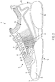
- FIG. 2 is a medial side view of the shoe shown in FIG. 1 .
- FIG. 3 is a lateral side view of the shoe shown in FIG. 1
- FIG. 4 is a top view of the shoe shown in FIG. 1 .
- FIG. 5 is an exploded view of the shoe shown in FIG. 1 .
- FIG. 6 is a medial side view of the sole of the shoe shown in FIG. 1 .
- FIG. 7 is a lateral side view of the sole of the shoe shown in FIG. 1 .
- FIG. 8 is a top view of the midsole of the shoe shown in FIG. 1 .
- FIG. 9 is a front view of the midsole and the outsole of the shoe shown in FIG. 1 .
- FIG. 10 is a rear view of the sole of the shoe shown in FIG. 1 .
- FIG. 11 is a bottom view of the midsole and outsole of the shoe shown in FIG. 1 .
- FIG. 12 is a cross-sectional view taken along the line 12 - 12 .
- FIG. 13 is a perspective view of an embodiment of a shoe, the shoe including a stiffening member.
- FIG. 14 is a lateral view of the shoe shown in FIG. 13 .
- FIG. 15 is a medial view of the shoe shown in FIG. 13 .
- FIG. 16 is a top view of the shoe shown in FIG. 13 .
- FIG. 17 is an exploded view of the shoe shown in FIG. 13 .
- the shoe 10 includes a sole, generally indicated at 12 , and a knit upper, generally indicated at 14 .
- the sole 12 is secured to the upper 14 .
- the upper 14 is stitched, glued, or otherwise suitably secured to the sole 12 .
- the shoe 10 extends forward from a heel end 18 to a toe end 19 .
- the knit upper 14 has a knitted element 20 .
- the knitted element 20 is formed of a unitary one-piece construction during a knitting process on a knitting machine (not shown).
- the upper 14 including the knitted element 20 , includes a toe region 22 , a vamp region 24 , a throat region 26 , and a quarter region 28 .
- the vamp region includes a lateral vamp region 30 and a medial vamp region 32 .
- the toe region 22 extends longitudinally to the vamp region 24 .
- the vamp region 24 extends longitudinally and laterally to the throat region 26 .
- the lateral vamp region 30 extends laterally and in a lateral direction from the throat region 26 .
- the medial vamp region 32 extends laterally and in a medial direction from the throat region 26 .
- the vamp region extends longitudinally to the quarter region 28 .
- the knitted element 20 includes an integral tongue 27 within the throat region 26 .
- the integral tongue 27 is seamlessly connected with adjacent regions of the knitted element 20 .
- the integral tongue 27 is seamlessly connected with the lateral vamp region 30 and the medial vamp region 32 .
- the integrated tongue 27 makes the upper 14 a sock-like upper.
- the sole 12 extends longitudinally from a sole heel end 34 to a sole toe end 36 .
- the sole 12 further extends transversely from a sole lateral edge 38 to a sole medial edge 40 .
- the sole includes a heel region 42 , a midfoot region 44 , a ball region 46 and a toe region 48 .
- the heel region 42 extends longitudinally from the sole heel end 34 to the midfoot region 44 .
- the midfoot region 44 extends longitudinally from the heel region 42 to the ball region 46 .
- the midfoot region 44 has a lateral midfoot region 50 and a medial midfoot region 52 .
- the lateral midfoot region 50 extends transversely from the lateral edge 38 to the medial midfoot region 52 .
- the medial midfoot region 52 extends transversely from the medial edge 40 to the lateral midfoot region 50 .
- the ball region 46 of the sole 12 extends longitudinally from the midfoot region 44 to the toe region 48 .
- the toe region 48 extends longitudinally from the ball region 46 to the sole toe end 36 .
- the sole 12 includes a sole member 54 and a molded chassis 56 .
- the sole member 54 extends from the sole heel end 34 to the sole toe end 36 .
- the molded chassis 56 is coupled to the sole member 54 .
- the molded chassis 56 is coupled to the sole member 54 with one or more of adhesive, stitching, or other suitable material or technique.
- the molded chassis 56 has at least a midfoot region 58 .
- the midfoot region 58 extends upwardly above a portion of the upper 14 .
- the midfoot region 58 of the molded chassis member 56 is in the midfoot region of the sole 44 .
- the shoe 10 further includes a lateral stiffening member 60 and a medial stiffening member 62 .
- Both the lateral stiffening member 60 and the medial stiffening member 62 are adapted and configured to stiffen the upper 14 .
- the stiffening members are coupled to the knitted element 20 (e.g., using stitching, adhesive, or the like) such that stretching between adjacent rows and/or columns of stitches is limited.
- the stiffening members are constructed of a material that has a higher resistance to stretching (e.g., a higher Young's Modulus) than that of the knitted element 20 .
- the stiffening members are coupled to the upper 14 , the overall stretchiness of the upper 14 is limited in one or more directions by the stiffening members.
- the stiffening members are constructed of leather, imitation leather, plastic, or other suitable materials. As a result of the interlinking of rows and/or columns of stitches and/or the higher stretch resistance of the stiffening members, stretching of the upper 14 in one or more directions is limited by the stiffening members coupled to the upper 14 .
- the lateral stiffening member 60 is coupled to the upper 14 in the lateral vamp region 30 .
- the lower edge of the lateral stiffening member 60 is stitched to the knitted element 20 in the lateral vamp region 30 .
- the lateral stiffening member 60 is adhered to the knitted element 20 .
- the lateral stiffening member 60 is coupled to the knitted element 20 adjacent the throat region 26 .
- the medial stiffening member 62 is coupled to the upper 14 in the medial vamp region 32 .
- the lower edge of the medial stiffening member 62 is stitched to the knitted element 20 in the medial vamp region 32 .
- the medial stiffening member 62 is adhered to the knitted element 20 .
- the medial stiffening member 62 is coupled to the knitted element 20 adjacent the throat region 26 .
- Both the medial stiffening member 62 and the lateral stiffening member 60 are spaced from the molded chassis member 56 .
- the lateral stiffening member 60 and the medial stiffening member 62 are also spaced from the sole member 54 .
- the lateral stiffening member 60 is operatively connected to the molded chassis 56 in at least the lateral midfoot region 50 .
- the lateral stiffening member 60 may also be operatively connected to the sole member 54 in the lateral midfoot region 50 .
- the lateral stiffening member 60 is further operatively coupled to the sole member 54 in the ball region 46 .
- the lateral stiffening member 60 is operatively coupled to the molded chassis 56 and/or the sole member 54 by a plurality of lateral reinforcing threads 64 .
- the lateral reinforcing threads 64 extend downwardly from the throat region 26 of the upper 14 and toward the sole member 54 .
- the plurality of lateral reinforcing threads 64 are adapted and configured to limit stretching of the knit upper 14 in at least one direction by securing adjacent rows of knit stitches.
- the plurality of lateral reinforcing threads 64 limits stretching of the knit upper 14 in a direction parallel with one or more of the plurality of lateral reinforcing threads 64 .
- Each reinforcing thread interlinks adjacent rows of stitches by passing through the stitches.
- the reinforcing threads may interlock adjacent columns.
- some of the lateral reinforcing threads may extend diagonally from the lateral stiffening member 60 to the molded chassis 56 and/or the sole member 54 .
- the lateral stiffening member 60 overlaps at least a portion of at least some of the plurality of lateral reinforcing threads 64 where the lateral stiffening member 60 is coupled to the upper 14 .
- the plurality of lateral reinforcing threads 64 limits stretching of the knit upper 14 in one or more of an upward direction, a lateral direction, and a longitudinal direction.
- the medial stiffening member 62 is operatively connected to the molded chassis 56 in at least the medial midfoot region 52 .
- the medial stiffening member 62 may also be operatively connected to the sole member 54 in the medial midfoot region 20 .
- the medial stiffening member 62 is further operatively coupled to the sole member 54 in the ball region 46 .
- the medial stiffening member 62 is operatively coupled to the molded chassis 56 and/or the sole member 54 by a plurality of medial reinforcing threads 66 .
- the medial reinforcing threads 66 extend downwardly from the throat region 26 of the upper 14 and toward the sole member 54 .
- the plurality of medial reinforcing threads 66 are adapted and configured to limit stretching of the knit upper 14 in at least one direction by securing adjacent rows of knit stitches.
- the plurality of medial reinforcing threads 66 limits stretching of the knit upper 14 in a direction parallel with one or more of the plurality of medial reinforcing threads 66 .
- Each reinforcing thread interlinks adjacent rows of stitches by passing through the stitches. This ties the adjacent rows of stitches together to limit stretching.
- the reinforcing threads may interlock adjacent columns.
- some of the medial reinforcing threads may extend diagonally from the medial stiffening member 62 to the molded chassis 56 and/or the sole member 54 .
- the medial stiffening member 62 overlaps at least a portion of at least some of the plurality of medial reinforcing threads 66 where the medial stiffening member 62 is coupled to the upper 14 .
- the plurality of medial reinforcing threads 66 limits stretching of the knit upper 14 in one or more of an upward direction, a lateral direction, and a longitudinal direction.
- the lateral stiffening member 60 and the medial stiffening member 62 each define at least one opening 68 adapted and configured to receive a shoe lace. With a lace passing through the openings 68 of the lateral and medial stiffening members 60 , 62 , the midfoot of the shoe 10 is able to be securely laced around a user's foot. By securing the two stiffening members together with the lacing, the overall stiffness of the shoe 10 is further increased. In this way, the looseness and high stretchiness of the knit construction of the upper 14 can be mitigated while retaining the benefits of a knit upper (e.g., breathability).
- a knit upper e.g., breathability
- the shoe 10 further includes a toe stiffening member 70 .
- the toe stiffening member 70 is coupled to the knitted element 20 in the toe region 22 .
- the toe stiffening member 70 is adhered to the knitted element 20 in the toe region 22 such that adjacent rows and/or columns of stitches are secured to one another thereby increasing the stiffness and limiting stretching of the knitted element 20 in the toe region 22 .
- the toe stiffening member 70 may be any suitable material, such as leather, plastic, transparent or semi-transparent plastic or polymer, or the like.
- the toe stiffening member 70 may also be attached to the knitted upper using any suitable method such as stitching, adhesive, or the like.
- the molded chassis 56 may also further stiffen the shoe 10 and/or otherwise provide support to a user's foot.
- the molded chassis 56 includes, in addition to the midfoot region 58 , a heel region 72 and a heel end region 74 .
- the heel region 72 and the heel end region 74 extend upwardly above a portion of the upper 14 .
- the heel end region 74 extends longitudinally from the sole heel end 34 to the heel region 72 of the molded chassis 56 .
- the heel region 72 of the molded chassis 56 extends longitudinally from the heel end region 74 of the molded chassis 56 to the midfoot region of the molded chassis 58 .
- the midfoot region 58 of the molded chassis 56 extends longitudinally from the heel region 72 of the molded chassis 56 toward the sole toe end 36 .
- the molded chassis member 56 generally decreases in height from the sole member 54 as the molded chassis member 56 extends from the heel end region 74 . At least a portion of the heel end region 74 of the molded chassis 56 extends vertically from the sole member 54 a first length. At least a portion of the heel region 72 of the molded chassis 56 extends vertically from the sole member 54 a second length, the second length being lesser than the first length. At least a portion of the midfoot region 58 of the molded chassis 56 extends vertically from the sole member 54 a third length, the third length being lesser than the second length.
- the molded chassis 56 includes a notched portion 76 in the heel region 72 .
- the notched portion 76 is concave and extends downwardly toward the sole member 54 .
- the notched portion 76 may increase flexibility of the molded chassis 56 in the heel region 72 , while the molded chassis 56 increases rigidity in other areas of the shoe 10 (e.g., to support the Achilles tendon, midfoot, etc.).
- the sole member 54 has a heel portion 78 , a midfoot portion 80 , a ball portion 82 , and a toe portion 84 .
- the heel portion 78 extends from the sole heel end 34 toward the midfoot region 44 and from the sole medial edge 40 to the sole lateral edge 38 .
- the midfoot portion 80 extends from the heel portion 78 to the ball portion 82 and being only in the lateral midfoot region 50 .
- the medial midfoot region 52 of the sole 12 is devoid of the midfoot portion 80 of the sole member 54 such that the chassis member 56 is visible as viewed in a bottom plan view.
- the ball portion 82 of the sole member 54 extends from the midfoot portion 80 toward the sole toe end 36 and from the sole medial edge 40 to the sole lateral edge 38 .
- the toe portion 84 of the sole member 54 extending from the ball portion 82 to the sole toe end 36 and from the sole medial edge 40 to the sole lateral edge 38 .
- the heel portion 78 of the sole member 54 curves inward and convexly from the sole medial edge 40 toward the sole toe end 36 and to a first apex 86 .
- the first apex 86 faces toward the sole toe end 36 .
- the heel portion 78 of the sole member 54 curves inward and convexly from the first apex 86 toward an inflection point 88 and a second apex 90 .
- the inflection point is positioned longitudinally between the first apex 86 and the second apex 90 .
- the heel portion 78 of the sole member 54 curves inward and concavely from the inflection point 88 to the second apex 90 .
- the second apex faces toward the sole heel end 34 .
- the heel portion 78 of the sole member 54 curves inward and concavely away from the second apex 90 toward the sole lateral edge 38 and tapers toward the sole lateral edge 38 as the heel portion 78 extends toward the sole toe 36 .
- the ball portion 82 of the sole member 54 curves inward and convexly from the sole medial edge 40 toward the sole heel end 34 and to a third apex 91 .
- the third apex faces toward the sole heel end 34 .
- the ball portion 82 curves inward and convexly from the third apex 91 toward the sole lateral edge 38 .
- the heel portion 78 of the sole member 54 is thicker than the ball portion 82 of the sole member 54 and thicker than the toe portion 84 of the sole member 54 .
- the sole member 54 is generally cup shaped defining a cavity 92 .
- the molded chassis 56 is positioned within the cavity 92 such that the sole member 54 extends upwardly above a portion of the molded chassis 56 .
- the shoe 10 further includes an outsole 93 .
- the outsole 93 is adapted and configured to engage with the ground.
- the outsole 93 extends from the sole heel end 34 to the sole toe end 36 and is coupled to the sole member 54 .
- the outsole includes a first outsole member 94 and a second outsole member 95 .
- the first outsole member 94 extends longitudinally from the sole heel end 34 to the midfoot region 44 .
- the second outsole member 95 extends longitudinally from the sole toe end 36 to the midfoot region 44 .
- the first outsole member 94 is separated from the second outsole member 95 . This increases flexibility of the sole 12 in the midfoot region 44 .
- the shoe 10 further includes an insole 96 and a shank 97 .
- the insole 96 is positioned within the upper 14 and extends from the toe end 19 to the heel end 18 .
- the insole further extends laterally between the lateral edge and medial edge of the shoe 10 .
- the insole includes a cutout 98 in the ball region, the midfoot region, and the heel region. The cutout is adapted and configured to receive the shank 97 such that the shank 97 is flush with the toe region of the insole 96 when positioned within the cutout 98 .
- the shank is coupled to the insole 96 and extends longitudinally and continuously from the heel end 78 to within the ball region of the shoe 10 .
- the shank 97 has a medial portion 99 and a lateral portion 100 .
- the medial portion of the shank 99 extends closer to toe end 19 than the lateral portion 100 of the shank 97 .
- this non-symmetrical configuration compensates for the shape of the sole member 54 which is not present in the medial midfoot region 52 of the sole 12 .
- the shank 97 stiffens the sole 12 and supports a user's foot within the shoe 10 .
- FIGS. 13-17 another embodiment of the shoe 10 is shown and is generally indicated with reference numeral 110 .
- the shoe 10 includes a molded chassis 56 and the shoe 110 includes a molded chassis 156 .
- the components of the shoe 110 are further described below.
- the shoe 110 does not include lateral or medial reinforcing threads.
- the shoe 110 has a single piece outsole 193 that may include several through openings.
- the molded chassis member 156 includes a through opening 201 in the heel region 172 .
- the shoe 110 includes a unitary one-piece stiffening member 203 . This is in contrast to the two separate stiffening members of the shoe 10 .
- the one-piece stiffening member 203 has a bottom portion 205 , a lateral side portion 207 , and a medial side portion 209 .
- the bottom portion 205 extending laterally between a first end 211 and a second end 213 , the second opposite the first end.
- the lateral side portion 207 extends upwardly from the first end 211 of the bottom portion 205 .
- the medial side portion 209 extends upwardly from the second end 213 of the bottom portion 205 .
- the stiffening member 203 is positioned between the molded chassis 156 and the upper 114 .
- the bottom portion 205 is in contact with the midfoot region 158 of the molded chassis member 156 (e.g., the bottom portio 205 is stitched, glued or otherwise attached to the molded chassis member 156 in the midfoot region 158 ).
- the upper 114 is positioned over the bottom portion 205 and between the lateral side portion 207 and the medial side portion 209 .
- the upper 114 may be secured to the stiffening member 203 .
- the upper 114 may be stitched or glued to the bottom portion 205 .
- the lateral side portion 207 and the medial side portion 209 are not coupled to the upper 114 but are capable of moving independently from the upper 114 .
- the stiffening 203 stiffens the upper 114 when the shoe 110 is laced, as the laces pass through openings 168 in the stiffening member 203 .
- the stiffening member 203 is constructed of a stiffer material than the knit upper 114 .
- the stiffening member 203 is constructed of leather, imitation leather, rubber, plastic, or any other suitable material.
- the lateral side portion 207 and/or medial side portion 209 are coupled to the upper (e.g., stitched or glued to the upper).
- the wedge shoe may be any type of wedge shoe, such as a wedge sandal, a wedge pump, an open-toe wedge, a platform wedge, etc.
- the breadth and scope of the present disclosure should not be limited by any of the above-described exemplary embodiments, but should be defined only in accordance with the following claims appended hereto and their equivalents
Landscapes
- Footwear And Its Accessory, Manufacturing Method And Apparatuses (AREA)
Abstract
Description
Claims (18)
Priority Applications (1)
| Application Number | Priority Date | Filing Date | Title |
|---|---|---|---|
| US15/996,684 US10772382B2 (en) | 2018-06-04 | 2018-06-04 | Shoe having stiffening features |
Applications Claiming Priority (1)
| Application Number | Priority Date | Filing Date | Title |
|---|---|---|---|
| US15/996,684 US10772382B2 (en) | 2018-06-04 | 2018-06-04 | Shoe having stiffening features |
Publications (2)
| Publication Number | Publication Date |
|---|---|
| US20190365048A1 US20190365048A1 (en) | 2019-12-05 |
| US10772382B2 true US10772382B2 (en) | 2020-09-15 |
Family
ID=68694759
Family Applications (1)
| Application Number | Title | Priority Date | Filing Date |
|---|---|---|---|
| US15/996,684 Active 2038-08-22 US10772382B2 (en) | 2018-06-04 | 2018-06-04 | Shoe having stiffening features |
Country Status (1)
| Country | Link |
|---|---|
| US (1) | US10772382B2 (en) |
Cited By (20)
| Publication number | Priority date | Publication date | Assignee | Title |
|---|---|---|---|---|
| USD914351S1 (en) * | 2020-07-24 | 2021-03-30 | Nike, Inc. | Shoe |
| USD928466S1 (en) * | 2020-07-21 | 2021-08-24 | Qinshan Xie | Shoe |
| USD932174S1 (en) * | 2020-12-14 | 2021-10-05 | Nike, Inc. | Shoe |
| USD938711S1 (en) * | 2019-04-10 | 2021-12-21 | Brooks Sports, Inc. | Shoe upper |
| USD943907S1 (en) * | 2020-01-21 | 2022-02-22 | Cole Haan Llc | Shoe |
| USD955702S1 (en) * | 2020-02-10 | 2022-06-28 | Keekoo Inc | Shoe |
| USD959810S1 (en) * | 2020-10-22 | 2022-08-09 | Brooks Sports, Inc. | Shoe |
| USD964002S1 (en) * | 2020-12-22 | 2022-09-20 | Nicholas Andrew Oxley | Shoe |
| USD964724S1 (en) * | 2021-09-01 | 2022-09-27 | Nike, Inc. | Shoe |
| USD980587S1 (en) * | 2021-06-11 | 2023-03-14 | Mounttech Hk Limited | Pair of running shoes |
| USD982891S1 (en) * | 2022-03-31 | 2023-04-11 | Nike, Inc. | Shoe |
| USD988707S1 (en) * | 2022-10-07 | 2023-06-13 | Nike, Inc. | Shoe |
| USD988642S1 (en) * | 2020-10-23 | 2023-06-13 | Columbia Sportswear North America, Inc. | Article of footwear |
| USD998291S1 (en) * | 2019-10-08 | 2023-09-12 | Sorel Corporation | Article of footwear |
| USD1000082S1 (en) * | 2022-02-28 | 2023-10-03 | leguano GmbH | Shoe |
| USD1002155S1 (en) * | 2020-03-13 | 2023-10-24 | Hero Gmbh & Co. Kg | Shoe |
| USD1007135S1 (en) * | 2023-03-22 | 2023-12-12 | Nike, Inc. | Shoe |
| USD1010281S1 (en) * | 2019-12-27 | 2024-01-09 | Columbia Sportswear North America, Inc. | Article of footwear |
| EP4324354A1 (en) * | 2022-08-18 | 2024-02-21 | ASICS Corporation | Shoe and method of manufacturing shoe |
| USD1018005S1 (en) * | 2022-03-21 | 2024-03-19 | Adidas Ag | Shoe |
Families Citing this family (47)
| Publication number | Priority date | Publication date | Assignee | Title |
|---|---|---|---|---|
| EP3488724B1 (en) * | 2016-07-19 | 2021-01-27 | ASICS Corporation | Footwear |
| USD862855S1 (en) * | 2018-05-18 | 2019-10-15 | Nike, Inc. | Shoe |
| USD900458S1 (en) * | 2018-05-31 | 2020-11-03 | Cole Haan Llc | Shoe |
| USD885729S1 (en) * | 2018-06-01 | 2020-06-02 | Cole Haan Llc | Shoe sole |
| USD893151S1 (en) * | 2018-06-04 | 2020-08-18 | Cole Haan Llc | Shoe sole |
| USD892481S1 (en) * | 2018-06-04 | 2020-08-11 | Cole Haan Llc | Shoe sole |
| USD879438S1 (en) * | 2018-08-09 | 2020-03-31 | Reebok International Limited | Shoe |
| EP3797632A4 (en) * | 2018-12-11 | 2022-01-12 | ASICS Corporation | Shoe |
| USD903257S1 (en) * | 2019-04-08 | 2020-12-01 | Cole Haan Llc | Shoe |
| USD917139S1 (en) * | 2019-05-06 | 2021-04-27 | Iw Apparel, Llc | Footwear tread |
| USD959101S1 (en) * | 2019-09-24 | 2022-08-02 | Adidas Ag | Shoe |
| USD1010282S1 (en) * | 2019-10-08 | 2024-01-09 | Columbia Sportswear North America, Inc. | Article of footwear |
| USD899047S1 (en) * | 2019-11-27 | 2020-10-20 | Nike, Inc. | Shoe |
| USD899044S1 (en) * | 2019-11-27 | 2020-10-20 | Nike, Inc. | Shoe |
| USD899042S1 (en) * | 2019-11-27 | 2020-10-20 | Nike, Inc. | Shoe |
| USD899039S1 (en) * | 2019-11-27 | 2020-10-20 | Nike, Inc. | Shoe |
| USD899041S1 (en) * | 2019-11-27 | 2020-10-20 | Nike, Inc. | Shoe |
| USD899046S1 (en) * | 2019-11-27 | 2020-10-20 | Nike, Inc. | Shoe |
| USD971574S1 (en) * | 2019-11-27 | 2022-12-06 | Cole Haan Llc | Shoe |
| USD899040S1 (en) * | 2019-11-27 | 2020-10-20 | Nike, Inc. | Shoe |
| USD899045S1 (en) * | 2019-11-27 | 2020-10-20 | Nike, Inc. | Shoe |
| USD899043S1 (en) * | 2019-11-27 | 2020-10-20 | Nike, Inc. | Shoe |
| USD929102S1 (en) * | 2019-12-04 | 2021-08-31 | Nike, Inc. | Shoe |
| USD929099S1 (en) * | 2019-12-04 | 2021-08-31 | Nike, Inc. | Shoe |
| USD929101S1 (en) * | 2019-12-04 | 2021-08-31 | Nike, Inc. | Shoe |
| USD925199S1 (en) * | 2020-03-31 | 2021-07-20 | Nike, Inc. | Shoe |
| MX2022014396A (en) * | 2020-05-18 | 2023-02-22 | Satyajit Mittal | Improved expandable shoe capable to grow with a wearer/user's feet for more than three sizes. |
| USD947508S1 (en) * | 2020-06-10 | 2022-04-05 | Nike, Inc. | Shoe |
| USD946870S1 (en) * | 2020-06-10 | 2022-03-29 | Nike, Inc. | Shoe |
| USD955717S1 (en) * | 2020-08-25 | 2022-06-28 | Nike, Inc. | Shoe |
| USD1003017S1 (en) * | 2020-09-24 | 2023-10-31 | Puma SE | Shoe |
| USD932157S1 (en) * | 2020-09-29 | 2021-10-05 | Nike, Inc. | Shoe |
| USD938149S1 (en) * | 2020-09-29 | 2021-12-14 | Nike, Inc. | Shoe |
| USD929725S1 (en) * | 2021-01-13 | 2021-09-07 | Nike, Inc. | Cushioning device for footwear |
| USD929100S1 (en) * | 2021-01-13 | 2021-08-31 | Nike, Inc. | Cushioning device for footwear |
| USD929726S1 (en) * | 2021-01-13 | 2021-09-07 | Nike, Inc. | Cushioning device for footwear |
| USD929723S1 (en) * | 2021-01-13 | 2021-09-07 | Nike, Inc. | Cushioning device for footwear |
| USD929724S1 (en) * | 2021-01-13 | 2021-09-07 | Nike, Inc. | Cushioning device for footwear |
| USD984792S1 (en) * | 2021-05-06 | 2023-05-02 | Veja Fair Trade Sarl | Footwear |
| USD1035233S1 (en) | 2021-10-05 | 2024-07-16 | Puma SE | Shoe |
| USD1041830S1 (en) | 2021-11-11 | 2024-09-17 | Puma SE | Shoe |
| USD1041142S1 (en) | 2022-03-04 | 2024-09-10 | Puma SE | Shoe |
| USD1014945S1 (en) * | 2022-03-18 | 2024-02-20 | Nike, Inc. | Shoe |
| USD1023542S1 (en) * | 2022-05-31 | 2024-04-23 | Nike, Inc. | Shoe |
| USD1028432S1 (en) * | 2022-10-07 | 2024-05-28 | Salomon, S.A.S. | Footwear article |
| USD1036067S1 (en) * | 2023-09-29 | 2024-07-23 | Nike, Inc. | Shoe |
| USD1033024S1 (en) * | 2023-09-29 | 2024-07-02 | Nike, Inc. | Shoe |
Citations (61)
| Publication number | Priority date | Publication date | Assignee | Title |
|---|---|---|---|---|
| US4468870A (en) | 1983-01-24 | 1984-09-04 | Sternberg Joseph E | Bowling shoe |
| US4584783A (en) | 1982-05-10 | 1986-04-29 | Kaepa, Inc. | Shoe tongue holder assembly |
| USD325464S (en) | 1991-02-01 | 1992-04-21 | Nike, Inc. | Midsole profile |
| USD330973S (en) | 1991-12-13 | 1992-11-17 | Nike, Inc. | Shoe sole bottom |
| USD335385S (en) | 1989-03-17 | 1993-05-11 | Kanechika Co., Ltd. | Sport shoe |
| USD348561S (en) | 1993-10-13 | 1994-07-12 | Nike, Inc. | Shoe upper |
| US6108943A (en) | 1998-01-30 | 2000-08-29 | Nike, Inc. | Article of footwear having medial and lateral sides with differing characteristics |
| USD449426S1 (en) | 2000-10-02 | 2001-10-23 | Tod's S.P.A. | Footwear |
| USD542018S1 (en) | 2005-11-14 | 2007-05-08 | Wolverine World Wide, Inc. | Footwear upper |
| USD550933S1 (en) | 2005-06-22 | 2007-09-18 | Lacoste Alligator S.A. | Shoe |
| USD556979S1 (en) | 2005-08-04 | 2007-12-11 | Vibram S.P.A. | Footwear |
| USD565283S1 (en) | 2006-06-15 | 2008-04-01 | Nike, Inc. | Shoe |
| US7444763B2 (en) | 2003-01-21 | 2008-11-04 | Nike, Inc. | Footwear with separable upper and sole structure |
| USD583141S1 (en) | 2008-09-11 | 2008-12-23 | Nike, Inc. | Shoe upper |
| USD595046S1 (en) | 2009-04-14 | 2009-06-30 | Nike, Inc. | Shoe upper |
| USD604480S1 (en) | 2008-02-27 | 2009-11-24 | Tod's S.P.A. | Shoe |
| USD614387S1 (en) | 2010-01-20 | 2010-04-27 | Nike, Inc. | Shoe upper |
| US20100154256A1 (en) * | 2008-12-18 | 2010-06-24 | Nike, Inc. | Article Of Footwear Having An Upper Incorporating A Knitted Component |
| USD623841S1 (en) | 2010-07-16 | 2010-09-21 | Nike, Inc. | Shoe upper |
| US20110119959A1 (en) * | 2009-11-25 | 2011-05-26 | Keith Bodner | External stabilizing structure for work boots |
| USD643204S1 (en) | 2011-05-31 | 2011-08-16 | Nike, Inc. | Shoe upper |
| USD643206S1 (en) | 2011-05-31 | 2011-08-16 | Nike, Inc. | Shoe upper |
| USD653442S1 (en) | 2011-11-09 | 2012-02-07 | Nike, Inc. | Shoe upper |
| US20120233882A1 (en) * | 2011-03-15 | 2012-09-20 | NIKE. Inc. | Article Of Footwear Incorporating A Knitted Component |
| USD683130S1 (en) | 2012-11-30 | 2013-05-28 | Nike, Inc. | Shoe upper |
| USD701036S1 (en) | 2013-11-27 | 2014-03-18 | Nike, Inc. | Shoe upper |
| USD707032S1 (en) | 2013-08-30 | 2014-06-17 | Nike, Inc. | Shoe upper |
| USD707027S1 (en) | 2012-05-07 | 2014-06-17 | Nike, Inc. | Shoe upper |
| USD714034S1 (en) | 2012-09-20 | 2014-09-30 | Tod's S.P.A. | Shoe |
| USD716540S1 (en) | 2014-05-31 | 2014-11-04 | Nike, Inc. | Shoe upper |
| USD720522S1 (en) | 2014-05-31 | 2015-01-06 | Nike, Inc. | Shoe upper |
| USD722225S1 (en) | 2014-08-29 | 2015-02-10 | Nike, Inc. | Shoe upper |
| USD722224S1 (en) | 2014-08-29 | 2015-02-10 | Nike, Inc. | Shoe upper |
| USD728205S1 (en) | 2013-05-20 | 2015-05-05 | Acushnet Company | Golf shoe |
| USD745771S1 (en) | 2014-04-11 | 2015-12-22 | Nike, Inc. | Shoe upper |
| USD752332S1 (en) | 2015-05-29 | 2016-03-29 | Nike, Inc. | Shoe upper |
| USD756621S1 (en) | 2014-11-26 | 2016-05-24 | Acushnet Company | Golf shoe upper |
| US20160286903A1 (en) * | 2015-04-02 | 2016-10-06 | Boa Technology, Inc. | Methods and systems for lace to lace coupling |
| USD778569S1 (en) | 2015-12-29 | 2017-02-14 | Nike, Inc. | Shoe upper |
| USD780431S1 (en) | 2015-11-16 | 2017-03-07 | Nike, Inc. | Shoe upper |
| US20170071291A1 (en) * | 2015-09-11 | 2017-03-16 | Nike, Inc. | Method Of Manufacturing Article Of Footwear With Graduated Projections |
| USD781556S1 (en) | 2015-08-18 | 2017-03-21 | Nike, Inc. | Shoe upper |
| USD783975S1 (en) | 2015-08-17 | 2017-04-18 | Nike, Inc. | Shoe |
| USD783992S1 (en) | 2016-01-06 | 2017-04-18 | Nike, Inc. | Shoe upper |
| USD783986S1 (en) | 2013-03-15 | 2017-04-18 | Nike, Inc. | Shoe upper |
| USD784679S1 (en) | 2015-12-29 | 2017-04-25 | Nike, Inc. | Shoe upper |
| USD796819S1 (en) | 2016-01-21 | 2017-09-12 | Nike, Inc. | Shoe upper |
| USD801664S1 (en) | 2017-02-20 | 2017-11-07 | Nike, Inc. | Shoe upper |
| US20170370027A1 (en) * | 2016-06-27 | 2017-12-28 | Nike, Inc. | Textile including bulking yarn |
| USD809270S1 (en) | 2016-07-29 | 2018-02-06 | Nike, Inc. | Shoe upper |
| USD809749S1 (en) | 2016-07-18 | 2018-02-13 | Grendene S.A. | Shoe |
| USD809768S1 (en) | 2016-11-16 | 2018-02-13 | Nike, Inc. | Shoe upper |
| USD817609S1 (en) | 2016-07-08 | 2018-05-15 | Cole Haan Llc | Shoe |
| USD821712S1 (en) | 2017-10-20 | 2018-07-03 | Nike, Inc. | Shoe midsole |
| USD822354S1 (en) | 2016-03-23 | 2018-07-10 | Adidas Ag | Shoe |
| USD833731S1 (en) | 2018-05-25 | 2018-11-20 | Nike, Inc. | Shoe |
| USD834294S1 (en) | 2016-11-12 | 2018-11-27 | Nike, Inc. | Shoe |
| USD840664S1 (en) | 2017-08-11 | 2019-02-19 | Nike, Inc. | Shoe |
| USD841973S1 (en) | 2017-08-11 | 2019-03-05 | Nike, Inc. | Shoe |
| USD845591S1 (en) | 2017-07-14 | 2019-04-16 | Ara Shoes Ag | Shoe |
| USD849374S1 (en) | 2018-02-26 | 2019-05-28 | Hermes Sellier (Société par Actions Simplifiée) | Sports shoe |
Family Cites Families (2)
| Publication number | Priority date | Publication date | Assignee | Title |
|---|---|---|---|---|
| US4676010A (en) * | 1985-06-10 | 1987-06-30 | Quabaug Corporation | Vulcanized composite sole for footwear |
| US8973410B1 (en) * | 2014-02-03 | 2015-03-10 | Nike, Inc. | Method of knitting a gusseted tongue for a knitted component |
-
2018
- 2018-06-04 US US15/996,684 patent/US10772382B2/en active Active
Patent Citations (62)
| Publication number | Priority date | Publication date | Assignee | Title |
|---|---|---|---|---|
| US4584783A (en) | 1982-05-10 | 1986-04-29 | Kaepa, Inc. | Shoe tongue holder assembly |
| US4468870A (en) | 1983-01-24 | 1984-09-04 | Sternberg Joseph E | Bowling shoe |
| USD335385S (en) | 1989-03-17 | 1993-05-11 | Kanechika Co., Ltd. | Sport shoe |
| USD325464S (en) | 1991-02-01 | 1992-04-21 | Nike, Inc. | Midsole profile |
| USD330973S (en) | 1991-12-13 | 1992-11-17 | Nike, Inc. | Shoe sole bottom |
| USD348561S (en) | 1993-10-13 | 1994-07-12 | Nike, Inc. | Shoe upper |
| US6108943A (en) | 1998-01-30 | 2000-08-29 | Nike, Inc. | Article of footwear having medial and lateral sides with differing characteristics |
| USD449426S1 (en) | 2000-10-02 | 2001-10-23 | Tod's S.P.A. | Footwear |
| US7444763B2 (en) | 2003-01-21 | 2008-11-04 | Nike, Inc. | Footwear with separable upper and sole structure |
| USD550933S1 (en) | 2005-06-22 | 2007-09-18 | Lacoste Alligator S.A. | Shoe |
| USD556979S1 (en) | 2005-08-04 | 2007-12-11 | Vibram S.P.A. | Footwear |
| USD542018S1 (en) | 2005-11-14 | 2007-05-08 | Wolverine World Wide, Inc. | Footwear upper |
| USD565283S1 (en) | 2006-06-15 | 2008-04-01 | Nike, Inc. | Shoe |
| USD604480S1 (en) | 2008-02-27 | 2009-11-24 | Tod's S.P.A. | Shoe |
| USD583141S1 (en) | 2008-09-11 | 2008-12-23 | Nike, Inc. | Shoe upper |
| US20100154256A1 (en) * | 2008-12-18 | 2010-06-24 | Nike, Inc. | Article Of Footwear Having An Upper Incorporating A Knitted Component |
| USD595046S1 (en) | 2009-04-14 | 2009-06-30 | Nike, Inc. | Shoe upper |
| US20110119959A1 (en) * | 2009-11-25 | 2011-05-26 | Keith Bodner | External stabilizing structure for work boots |
| USD614387S1 (en) | 2010-01-20 | 2010-04-27 | Nike, Inc. | Shoe upper |
| USD623841S1 (en) | 2010-07-16 | 2010-09-21 | Nike, Inc. | Shoe upper |
| US20120233882A1 (en) * | 2011-03-15 | 2012-09-20 | NIKE. Inc. | Article Of Footwear Incorporating A Knitted Component |
| USD643204S1 (en) | 2011-05-31 | 2011-08-16 | Nike, Inc. | Shoe upper |
| USD643206S1 (en) | 2011-05-31 | 2011-08-16 | Nike, Inc. | Shoe upper |
| USD653442S1 (en) | 2011-11-09 | 2012-02-07 | Nike, Inc. | Shoe upper |
| USD709280S1 (en) | 2012-05-07 | 2014-07-22 | Nike, Inc. | Shoe upper |
| USD707027S1 (en) | 2012-05-07 | 2014-06-17 | Nike, Inc. | Shoe upper |
| USD714034S1 (en) | 2012-09-20 | 2014-09-30 | Tod's S.P.A. | Shoe |
| USD683130S1 (en) | 2012-11-30 | 2013-05-28 | Nike, Inc. | Shoe upper |
| USD783986S1 (en) | 2013-03-15 | 2017-04-18 | Nike, Inc. | Shoe upper |
| USD728205S1 (en) | 2013-05-20 | 2015-05-05 | Acushnet Company | Golf shoe |
| USD707032S1 (en) | 2013-08-30 | 2014-06-17 | Nike, Inc. | Shoe upper |
| USD701036S1 (en) | 2013-11-27 | 2014-03-18 | Nike, Inc. | Shoe upper |
| USD745771S1 (en) | 2014-04-11 | 2015-12-22 | Nike, Inc. | Shoe upper |
| USD716540S1 (en) | 2014-05-31 | 2014-11-04 | Nike, Inc. | Shoe upper |
| USD720522S1 (en) | 2014-05-31 | 2015-01-06 | Nike, Inc. | Shoe upper |
| USD722224S1 (en) | 2014-08-29 | 2015-02-10 | Nike, Inc. | Shoe upper |
| USD722225S1 (en) | 2014-08-29 | 2015-02-10 | Nike, Inc. | Shoe upper |
| USD756621S1 (en) | 2014-11-26 | 2016-05-24 | Acushnet Company | Golf shoe upper |
| US20160286903A1 (en) * | 2015-04-02 | 2016-10-06 | Boa Technology, Inc. | Methods and systems for lace to lace coupling |
| USD752332S1 (en) | 2015-05-29 | 2016-03-29 | Nike, Inc. | Shoe upper |
| USD783975S1 (en) | 2015-08-17 | 2017-04-18 | Nike, Inc. | Shoe |
| USD781556S1 (en) | 2015-08-18 | 2017-03-21 | Nike, Inc. | Shoe upper |
| US20170071291A1 (en) * | 2015-09-11 | 2017-03-16 | Nike, Inc. | Method Of Manufacturing Article Of Footwear With Graduated Projections |
| USD780431S1 (en) | 2015-11-16 | 2017-03-07 | Nike, Inc. | Shoe upper |
| USD778569S1 (en) | 2015-12-29 | 2017-02-14 | Nike, Inc. | Shoe upper |
| USD784679S1 (en) | 2015-12-29 | 2017-04-25 | Nike, Inc. | Shoe upper |
| USD783992S1 (en) | 2016-01-06 | 2017-04-18 | Nike, Inc. | Shoe upper |
| USD796819S1 (en) | 2016-01-21 | 2017-09-12 | Nike, Inc. | Shoe upper |
| USD822354S1 (en) | 2016-03-23 | 2018-07-10 | Adidas Ag | Shoe |
| US20170370027A1 (en) * | 2016-06-27 | 2017-12-28 | Nike, Inc. | Textile including bulking yarn |
| USD817609S1 (en) | 2016-07-08 | 2018-05-15 | Cole Haan Llc | Shoe |
| USD809749S1 (en) | 2016-07-18 | 2018-02-13 | Grendene S.A. | Shoe |
| USD809270S1 (en) | 2016-07-29 | 2018-02-06 | Nike, Inc. | Shoe upper |
| USD834294S1 (en) | 2016-11-12 | 2018-11-27 | Nike, Inc. | Shoe |
| USD809768S1 (en) | 2016-11-16 | 2018-02-13 | Nike, Inc. | Shoe upper |
| USD801664S1 (en) | 2017-02-20 | 2017-11-07 | Nike, Inc. | Shoe upper |
| USD845591S1 (en) | 2017-07-14 | 2019-04-16 | Ara Shoes Ag | Shoe |
| USD840664S1 (en) | 2017-08-11 | 2019-02-19 | Nike, Inc. | Shoe |
| USD841973S1 (en) | 2017-08-11 | 2019-03-05 | Nike, Inc. | Shoe |
| USD821712S1 (en) | 2017-10-20 | 2018-07-03 | Nike, Inc. | Shoe midsole |
| USD849374S1 (en) | 2018-02-26 | 2019-05-28 | Hermes Sellier (Société par Actions Simplifiée) | Sports shoe |
| USD833731S1 (en) | 2018-05-25 | 2018-11-20 | Nike, Inc. | Shoe |
Cited By (22)
| Publication number | Priority date | Publication date | Assignee | Title |
|---|---|---|---|---|
| USD938711S1 (en) * | 2019-04-10 | 2021-12-21 | Brooks Sports, Inc. | Shoe upper |
| USD998291S1 (en) * | 2019-10-08 | 2023-09-12 | Sorel Corporation | Article of footwear |
| USD1010281S1 (en) * | 2019-12-27 | 2024-01-09 | Columbia Sportswear North America, Inc. | Article of footwear |
| USD943907S1 (en) * | 2020-01-21 | 2022-02-22 | Cole Haan Llc | Shoe |
| USD955702S1 (en) * | 2020-02-10 | 2022-06-28 | Keekoo Inc | Shoe |
| USD1002155S1 (en) * | 2020-03-13 | 2023-10-24 | Hero Gmbh & Co. Kg | Shoe |
| USD928466S1 (en) * | 2020-07-21 | 2021-08-24 | Qinshan Xie | Shoe |
| USD914351S1 (en) * | 2020-07-24 | 2021-03-30 | Nike, Inc. | Shoe |
| USD959810S1 (en) * | 2020-10-22 | 2022-08-09 | Brooks Sports, Inc. | Shoe |
| USD987240S1 (en) | 2020-10-22 | 2023-05-30 | Brooks Sports, Inc. | Shoe sole |
| USD988642S1 (en) * | 2020-10-23 | 2023-06-13 | Columbia Sportswear North America, Inc. | Article of footwear |
| USD932174S1 (en) * | 2020-12-14 | 2021-10-05 | Nike, Inc. | Shoe |
| USD964002S1 (en) * | 2020-12-22 | 2022-09-20 | Nicholas Andrew Oxley | Shoe |
| USD980587S1 (en) * | 2021-06-11 | 2023-03-14 | Mounttech Hk Limited | Pair of running shoes |
| USD964724S1 (en) * | 2021-09-01 | 2022-09-27 | Nike, Inc. | Shoe |
| USD1000082S1 (en) * | 2022-02-28 | 2023-10-03 | leguano GmbH | Shoe |
| USD1018005S1 (en) * | 2022-03-21 | 2024-03-19 | Adidas Ag | Shoe |
| USD1035255S1 (en) | 2022-03-21 | 2024-07-16 | Adidas Ag | Shoe |
| USD982891S1 (en) * | 2022-03-31 | 2023-04-11 | Nike, Inc. | Shoe |
| EP4324354A1 (en) * | 2022-08-18 | 2024-02-21 | ASICS Corporation | Shoe and method of manufacturing shoe |
| USD988707S1 (en) * | 2022-10-07 | 2023-06-13 | Nike, Inc. | Shoe |
| USD1007135S1 (en) * | 2023-03-22 | 2023-12-12 | Nike, Inc. | Shoe |
Also Published As
| Publication number | Publication date |
|---|---|
| US20190365048A1 (en) | 2019-12-05 |
Similar Documents
| Publication | Publication Date | Title |
|---|---|---|
| US10772382B2 (en) | Shoe having stiffening features | |
| CN113260268B (en) | Tongue-less upper with lacing system | |
| WO2019236188A1 (en) | Shoe having a structural knit region | |
| US12011058B2 (en) | Hinged footwear sole structure for foot entry and method of manufacturing | |
| US11058176B2 (en) | Sole structure with progressively angled traction elements | |
| US20200375320A1 (en) | Sole structure for article of footwear | |
| US10271614B2 (en) | Sole assembly for article of footwear | |
| US11129436B2 (en) | Golf shoe with natural motion structures | |
| US10342288B2 (en) | Shoe upper structure and shoe | |
| US8595957B2 (en) | Unitary upper and midsole | |
| US8677656B2 (en) | Athletic shoe with heel counter for maintaining shape of heel section | |
| US10292451B2 (en) | Sole plate for an article of footwear | |
| CN108135317A (en) | Footwear, particularly sport footwear | |
| US9930930B2 (en) | Shoe having a split welt | |
| US12070096B2 (en) | Article of footwear with midsole having varying hardness | |
| US20200170330A1 (en) | Shoe with Knit Upper | |
| US20170251762A1 (en) | Footwear Upper With Ribbed Panels | |
| US20230404211A1 (en) | Sole structures and articles of footwear having conformable heel counter structures | |
| US11937662B1 (en) | Upper for article of footwear incorporating a knitted butterfly workpiece | |
| US20230404215A1 (en) | Sole structures and articles of footwear having separate outsole and midsole components | |
| JP2021145686A (en) | Shoe | |
| US20240041164A1 (en) | Sole structures and articles of footwear having separate outsole and midsole components | |
| US20240023674A1 (en) | Article of footwear including a support flap | |
| JPS6244644Y2 (en) | ||
| CN118526045A (en) | Sole of shoe |
Legal Events
| Date | Code | Title | Description |
|---|---|---|---|
| FEPP | Fee payment procedure |
Free format text: ENTITY STATUS SET TO UNDISCOUNTED (ORIGINAL EVENT CODE: BIG.); ENTITY STATUS OF PATENT OWNER: LARGE ENTITY |
|
| AS | Assignment |
Owner name: COLE HAAN LLC, NEW YORK Free format text: ASSIGNMENT OF ASSIGNORS INTEREST;ASSIGNOR:FONTAINE, JONATHAN;REEL/FRAME:046726/0969 Effective date: 20180724 |
|
| AS | Assignment |
Owner name: JPMORGAN CHASE BANK, N.A., ILLINOIS Free format text: SECURITY INTEREST;ASSIGNOR:COLE HAAN LLC;REEL/FRAME:048355/0667 Effective date: 20190212 |
|
| STPP | Information on status: patent application and granting procedure in general |
Free format text: NON FINAL ACTION MAILED |
|
| STPP | Information on status: patent application and granting procedure in general |
Free format text: RESPONSE TO NON-FINAL OFFICE ACTION ENTERED AND FORWARDED TO EXAMINER |
|
| STPP | Information on status: patent application and granting procedure in general |
Free format text: NON FINAL ACTION MAILED |
|
| STPP | Information on status: patent application and granting procedure in general |
Free format text: NOTICE OF ALLOWANCE MAILED -- APPLICATION RECEIVED IN OFFICE OF PUBLICATIONS |
|
| AS | Assignment |
Owner name: ALTER DOMUS (US) LLC, AS COLLATERAL AGENT, ILLINOIS Free format text: PATENT SECURITY AGREEMENT;ASSIGNOR:COLE HAAN LLC;REEL/FRAME:053100/0028 Effective date: 20200630 |
|
| STPP | Information on status: patent application and granting procedure in general |
Free format text: PUBLICATIONS -- ISSUE FEE PAYMENT VERIFIED |
|
| STCF | Information on status: patent grant |
Free format text: PATENTED CASE |
|
| AS | Assignment |
Owner name: BANK OF AMERICA, N.A., MASSACHUSETTS Free format text: SECURITY AGREEMENT;ASSIGNOR:COLE HAAN LLC;REEL/FRAME:053770/0204 Effective date: 20200914 |
|
| AS | Assignment |
Owner name: COLE HAAN LLC, NEW HAMPSHIRE Free format text: RELEASE BY SECURED PARTY;ASSIGNOR:ALTER DOMUS (US) LLC, AS COLLATERAL AGENT;REEL/FRAME:064599/0780 Effective date: 20230815 Owner name: ACQUIOM AGENCY SERVICES LLC, AS COLLATERAL AGENT, COLORADO Free format text: SECURITY INTEREST;ASSIGNOR:COLE HAAN LLC;REEL/FRAME:064599/0077 Effective date: 20230815 |
|
| AS | Assignment |
Owner name: COLE HAAN LLC, NEW HAMPSHIRE Free format text: RELEASE OF SECURITY INTEREST RECORDED FEBRUARY 15, 2019, AT REEL 048355 AND FRAME 0667;ASSIGNOR:JPMORGAN CHASE BANK, N.A.;REEL/FRAME:064602/0407 Effective date: 20230815 |
|
| FEPP | Fee payment procedure |
Free format text: MAINTENANCE FEE REMINDER MAILED (ORIGINAL EVENT CODE: REM.); ENTITY STATUS OF PATENT OWNER: LARGE ENTITY |