EP3488711A1 - Filter manufacturing device and filter manufacturing method - Google Patents
Filter manufacturing device and filter manufacturing method Download PDFInfo
- Publication number
- EP3488711A1 EP3488711A1 EP16910479.1A EP16910479A EP3488711A1 EP 3488711 A1 EP3488711 A1 EP 3488711A1 EP 16910479 A EP16910479 A EP 16910479A EP 3488711 A1 EP3488711 A1 EP 3488711A1
- Authority
- EP
- European Patent Office
- Prior art keywords
- additive
- filter elements
- feeding
- filter
- air
- Prior art date
- Legal status (The legal status is an assumption and is not a legal conclusion. Google has not performed a legal analysis and makes no representation as to the accuracy of the status listed.)
- Granted
Links
Images


Classifications
-
- A—HUMAN NECESSITIES
- A24—TOBACCO; CIGARS; CIGARETTES; SIMULATED SMOKING DEVICES; SMOKERS' REQUISITES
- A24D—CIGARS; CIGARETTES; TOBACCO SMOKE FILTERS; MOUTHPIECES OF CIGARS OR CIGARETTES; MANUFACTURE OF TOBACCO SMOKE FILTERS OR MOUTHPIECES
- A24D3/00—Tobacco smoke filters, e.g. filter tips or filtering inserts; Filters specially adapted for simulated smoking devices; Mouthpieces of cigars or cigarettes
- A24D3/02—Manufacture of tobacco smoke filters
- A24D3/0204—Preliminary operations before the filter rod forming process, e.g. crimping, blooming
- A24D3/0212—Applying additives to filter materials
- A24D3/0225—Applying additives to filter materials with solid additives, e.g. incorporation of a granular product
-
- A—HUMAN NECESSITIES
- A24—TOBACCO; CIGARS; CIGARETTES; SIMULATED SMOKING DEVICES; SMOKERS' REQUISITES
- A24D—CIGARS; CIGARETTES; TOBACCO SMOKE FILTERS; MOUTHPIECES OF CIGARS OR CIGARETTES; MANUFACTURE OF TOBACCO SMOKE FILTERS OR MOUTHPIECES
- A24D3/00—Tobacco smoke filters, e.g. filter tips or filtering inserts; Filters specially adapted for simulated smoking devices; Mouthpieces of cigars or cigarettes
- A24D3/02—Manufacture of tobacco smoke filters
-
- A—HUMAN NECESSITIES
- A24—TOBACCO; CIGARS; CIGARETTES; SIMULATED SMOKING DEVICES; SMOKERS' REQUISITES
- A24D—CIGARS; CIGARETTES; TOBACCO SMOKE FILTERS; MOUTHPIECES OF CIGARS OR CIGARETTES; MANUFACTURE OF TOBACCO SMOKE FILTERS OR MOUTHPIECES
- A24D3/00—Tobacco smoke filters, e.g. filter tips or filtering inserts; Filters specially adapted for simulated smoking devices; Mouthpieces of cigars or cigarettes
- A24D3/02—Manufacture of tobacco smoke filters
- A24D3/0204—Preliminary operations before the filter rod forming process, e.g. crimping, blooming
- A24D3/0212—Applying additives to filter materials
- A24D3/0216—Applying additives to filter materials the additive being in the form of capsules, beads or the like
Definitions
- the present invention relates to a filter manufacturing apparatus and a filter manufacturing method.
- the additive is, for example, menthol crystals, perfume capsules, sepiolite, activated carbon, hydrotalcite, or silica grains.
- the additive is fed to each filter element or among filter elements mainly to modify components of mainstream smoke of a smoking article or possibly to characterize the appearance of the smoking article.
- fine grains fine powder resulting from crushing or powdering of a granular additive may scatter to surroundings.
- Many of such fine grains are collected and removed by suction air from a ventilation unit arranged in an additive feeding section of the filter manufacturing apparatus.
- suction air from a ventilation unit arranged in an additive feeding section of the filter manufacturing apparatus.
- some of the fine grains are suspended in the air, fall at a low speed, and thus reach not only the additive feeding section of the filter manufacturing apparatus but also other sections of the filter manufacturing apparatus. These fine grains adhere to and contaminate devices included in the filter manufacturing apparatus.
- the fine grains of the additive are likely to adhere to a discharge port for a plasticizer provided in a plasticizer feeding section of the filter manufacturing apparatus.
- a deposit of the fine grains having adhered to and accumulated on the discharge port grow and fall off the discharge port, disadvantageously significantly contaminating the devices included in the filter manufacturing apparatus.
- an object of the present invention is to provide a filter manufacturing apparatus and a filter manufacturing method capable of suppressing scatter of fine grains included in an additive to inhibit contamination of the apparatus.
- an aspect of the present invention is directed to a filter manufacturing apparatus including a transfer path through which filter elements for a smoking article is transferred and an additive feeding unit provided immediately above the transfer path to feed a granular additive to each of the filter elements or among the filter elements on the transfer path, wherein the additive feeding unit includes a classifier classifying the additive into coarse grains and fine grains based on granularity to remove the fine grains immediately before feeding the additive to each of the filter elements or among the filter elements.
- Another aspect of the present invention is directed to a filter manufacturing method including an additive feeding step of feeding, during transfer of filter elements for a smoking article along a transfer path, a granular additive from immediately above the transfer path to each of the filter elements or among the filter elements, wherein the additive feeding step includes a classifying process of classifying the additive into coarse grains and fine grains based on granularity to remove the fine grains immediately before feeding the additive to each of the filter elements or among the filter elements.
- a filter manufacturing apparatus 1 includes, as sections for manufacturing a filter rod, a tow treating section 2, an additive feeding section 4, a shaping section 6, and a wrapping section 8.
- the tow treating section 2 includes a bale 10 (not illustrated in the drawings) housing, for example, a filter material of cellulose acetate fibers, that is, a tow T.
- a tow path 12 for the tow T extends from the bale 10.
- the tow path 12 includes a primary banding jet 14, a guide 16, a secondary banding jet 18, a pair of pretension rollers 20, a pair of blooming rollers 22, a tertiary banding jet 24, a plasticizer feeding unit 26, and a pair of delivery rollers 28 sequentially arranged along the path 12 from the bale 10 side.
- the primary banding jet 14 jets compressed air from the bale 10 side toward the tow T.
- the jetted compressed air opens the tow T and appropriately stretches crimps in the tow T.
- the guide 16 When the tow T reaches the guide 16, the guide 16 orients a feeding direction for the tow T toward the secondary banding jet 18.
- the tow T subsequently passes through the secondary banding jet 18.
- the secondary banding jet 18 jets compressed air onto the tow T to further open the tow T to further stretch the crimps in the tow T.
- the tow T subsequently passes between the pair of pretension rollers 20.
- the pretension rollers 20 presses the opened tow T and applies a predetermined tension to the tow T in cooperation with the pair of blooming rollers 22, thus further stretching the crimps in the tow T.
- the blooming rollers 22 divide the opened tow T into a plurality of bundles and feed the bundles toward the tertiary banding jet 24.
- the tertiary banding jet 24 jets compressed air toward the division bundles, and the compressed air opens the division bundles.
- the division bundles spread in a width direction of the tow path 12 to form a flat filter web (filter element) WF.
- the filter web WF subsequently reaches the plasticizer feeding unit 26 provided immediately above a transfer path 30 for the filter web WF.
- the plasticizer feeding unit 26 includes a chamber 26A storing a plasticizer (triacetin) and a brush roll (not illustrated in the drawings) that rotates in the chamber 26A.
- the brush roll rotates in the chamber 26A to splash and make the liquid plasticizer misty.
- the misty plasticizer is discharged through a discharge port of the chamber 26A and adheres to the filter web WF (plasticizer feeding step).
- the filter web WF to which the plasticizer has been added is provided with tackiness as a result of a melting effect of the plasticizer on cellulose acetate fibers.
- the adjacent cellulose acetate fibers are combined with each other at a plurality of combination points due to the tackiness. These firm combination points of the filter web WF apply, when a filter is later shaped, sufficient hardness to the filter.
- the filter web WF subsequently passes between the pair of delivery rollers 28 and is fed from the delivery rollers 28 to the additive feeding section 4.
- the additive feeding section 4 includes the transfer path 30 for the filter web WF, and the transfer path 30 extends from the delivery rollers 28 to a trumpet guide 32 of a shaping section 6.
- the transfer path 30 includes a pair of nip rollers 34 and an additive feeding unit 36 sequentially arranged from the delivery roller 28 side.
- the nip rollers 34 apply a predetermined tension to the filter web WF in cooperation with the trumpet guide 32 to define the transfer path 30.
- the nip rollers 34 feed the filter web WF toward the additive feeding unit 36.
- the additive feeding unit 36 is provided immediately above the transfer path 30 to uniformly spray a granular additive, for example, granular activated carbon AC, onto the filter web WF on the transfer path 30 to feed the additive to the filter web WF.
- a granular additive for example, granular activated carbon AC
- the additive feeding unit 36 includes a classifier 38 classifying the activated carbon AC into coarse grains CG and fine grains FG based on granularity to remove the fine grains FG immediately before feeding the activated carbon AC to the filter web WF.
- the additive feeding unit 36 includes a feeder 40 and the classifier 38 sequentially arranged from an upper side.
- the feeder 40 includes a hopper 40A in which the activated carbon AC is stored and a vibrating conveyor 40B transferring, toward the classifier 38, the activated carbon AC falling through an outlet formed at a lower end of the hopper 40A.
- the classifier 38 includes a hopper 42 receiving the activated carbon AC conveyed along the vibrating conveyor 40B, a body 44 of the classifier 38 connected to a lower portion of the hopper 42, a discharge unit 46 connected to a lower portion of the body 44, a spraying unit (feeding means) 48 connected to a lower portion of the discharge unit 46, a high-pressure air blower (dispersed air feeding means) 50 connected to a side portion of the discharge unit 46, and a dust collector (recovery means) 52 and a forced air blower (forced air feeding means) 54 connected to the body 44.
- the body 44 is shaped like a cylinder for which an up-down direction corresponds to a radial direction.
- a dispersion chamber 56 and a trapping chamber 58 are adjacently formed in the body 44.
- the activated carbon AC is fed through an outlet formed at a lower end of the hopper 42.
- a line 50A extending from the high-pressure air blower 50 is connected to the discharge unit 46.
- the high-pressure air blower 50 feeds, to the dispersion chamber 56, dispersed air having pressure increased sequentially through the line 50A and the discharge unit 46.
- the dispersed air having flowed into the discharge unit 46 forms a rising air current, while the dispersed air having flowed into the dispersion chamber 56 forms a swirling air current swirling in the up-down direction to suitably disperse, into particles, the activated carbon AC present in the dispersion chamber 56.
- a screen 60 is arranged that separates the inside of the body 44 into the dispersion chamber 56 and the trapping chamber 58.
- the screen 60 is circular wire mesh formed of metal such as stainless steel and including fine meshes.
- the screen 60 has a large mesh size that inhibits the coarse grains CG of the activated carbon AC from passing from the dispersion chamber 56 to the trapping chamber 58 while permitting the fine grains FG of the activated carbon AC to pass from the dispersion chamber 56 to the trapping chamber 58.
- the dust collector 52 includes a body 52A, a dust collecting material 52B incorporated in the body 52A, a suction pump 52C connected to the body 52A above the dust collecting material 52B in the body 52A, a rotary valve 52D provided on an underside of the body 52A, a recovery box 52E arranged immediately below the rotary valve 52D, and a line 52F extending from a position of the body 52A below the dust collecting material 52B to the trapping chamber 58 of the body 44.
- the suction pump 52C sucks air in the dispersion chamber 56 in the body 44 from the trapping chamber 58 side sequentially through the body 52A, the dust collecting material 52B and the line 52F.
- the dust collector 52 recovers, on the trapping chamber 58 side, the fine grains FG having passed through the screen 60 in the dispersion chamber 56.
- the dust collector 52 further recovers the recovered fine grains FG in the recovery box 52E sequentially through the line 52F, the body 52A and the rotary valve 52D.
- the coarse grains CG may fall from the dispersion chamber 56 into the discharge unit 46 against the swirling air current of the dispersed air and fall from the discharge unit 46 against the rising air current of the dispersed air. These coarse grains CG are fed to the spraying unit 48 of the classifier 38.
- the spraying unit 48 includes a hopper 48A in which the coarse grains CG are stored.
- the hopper 48A includes an outlet at a lower end of the hopper 48A.
- the outlet is shaped like a slit that is open downward and that extends in a width direction of the filter web WF.
- a spraying roller 48B is arranged immediately below the outlet of the hopper 48A.
- the spraying roller 48B rotates to receive, on an outer peripheral surface of the spraying roller 48B, the coarse grains CG discharged from the hopper 48A and uniformly sprays the coarse grains CG onto the filter web WF.
- the classifier 38 further includes a cleaner 62 that cleans the screen 60.
- the cleaner 62 includes an air brush 62A, a motor 62B, and the above-described forced air blower 54.
- the air brush 62A is shaped like a rectangular parallelepiped as viewed from front and arranged to be movable along a rear surface 60A of the screen 60 corresponding to the trapping chamber 58 side.
- the motor 62B is coupled to a longitudinal center of the air brush 62A to rotationally drive the air brush 62A along the rear surface 60A in the direction of dashed arrows in FIG. 3 .
- a line 54A extending from the forced air blower 54 is in communication with a plurality of air jetting holes 62C (see FIG. 3 ) open on the rear surface 60A side of the air brush 62A.
- the forced air blower 54 jets forced air toward the rear surface 60A of the screen 60 through the air jetting holes 62C.
- the forced air is intermittently blown against every area of the screen 60 as a result of rotation of the air brush 62A. This prevents inhibition of the capability of the screen 60 of recovering the fine grains FG.
- the classifier 38 integrally includes the body 44 filtering the fine grains FG using the screen 60 while dispersing the activated carbon AC using the swirling dispersed air, and the above-described spraying unit 48 feeding the coarse grains CG having fallen against the dispersed air, to the filter web WF via the discharge unit 46.
- This implements the additive feeding unit 36 capable of executing a classifying process of classifying the activated carbon AC into the coarse grains CG and the fine grains FG based on granularity to remove the fine grains FG immediately before feeding the activated carbon AC to the filter web WF (additive feeding step).
- the filter web WF to which the coarse grains CG have been fed is transferred toward the trumpet guide 32 of the shaping section 6, and passes through the trumpet guide 32. At this time, the filter web WF is squeezed into a rod shape by the trumpet guide 32 and thus formed into a rod member WR.
- the trumpet guide 32 feeds the rod member WR to the wrapping section 8.
- a paper web WP is fed onto a stringer tape (not illustrated in the drawings), and the rod member WR fed from the trumpet guide 32 is laid on top of the paper web WP and bonded to the paper web WP.
- the rod member WR and the paper web WP subsequently travel over a shaping bed (not illustrated in the drawings) along with the stringer tape, while sequentially passing through a tongue, a wrapping former, a heater, a cooler, and the like (none of which are illustrated in the drawings).
- a continuous body of a charcoal filter rod is thus formed.
- the continuous body of the charcoal filter rod is then cut into individual charcoal filter rods using a rotary knife (not illustrated in the drawings) to complete manufacture of filters as final products.
- a sucker 66 used to collect the fine grains FG in the experiments was formed by utilizing a handy vacuum cleaner and fixedly abutting a suction tube 70 on a suction surface 66A of the vacuum cleaner via filter paper 68.
- Specifications of the sucker 66, the suction tube 70, and the filter paper 68 and additives (three types) used in the experiments are as follows.
- Table 1 indicates results for physical properties of the additives A to C.
- Additive A B C Median diameter (D50) um 705 330 337 Particle size distribution on % 0.05 0.00 0.00 1400 um pass % 0.93 - - 850 um pass % 46.99 - - 710 um pass % 50.54 - - 600 um pass % 1.40 0.02 0.07 500 um pass % 0.08 9.32 15.98 425 um pass % 0.01 31.77 33.77 355 um pass % 0.01 33.16 26.52 300 um pass % - 20.57 17.41 250 um pass % - 0.90 1.85 212 um pass % - 4.26 4.41 Apparent density Bulk density g/cm 3 0.527 0.397 0.385 Tapped density g/cm 3 0.554 0.423 0.414 Compressibility % 4.9 6.2 7.0 Angle of repose ° 31.0 34.2 33.6 Angle of spatula ° 26.1 29.2 28.5 Uniformity 1.2
- the medium diameter and the particle size distribution in Table 1 were measured using a dry sieving method.
- a vertical list of items in Table 1 from the apparent density to the floodability index was measured using Powder Tester, PT-X, Hosokawa Micron Corporation.
- the activated carbon test method hardness in Table 1 was measured based on JIS K1474 7.6.
- Table 2 indicates results of two measurement processes for the classifying capability for each of the additives A to C with a weight of approximately 13 to 20 kg when the additives were classified using the classifier 38 according to the present embodiment.
- [Table 2] Coarse grains Fine grains Remark on classification stat kg % g % A (first time) 20.25 99.928 14.52 0.072 Acceptable A (second time) 20.25 99.907 18.89 0.093 Acceptable B (first time) 12.98 98.632 7.39 0.056 Acceptable B (second time) 13.04 00.088 7.08 0.054 Acceptable C (first time) 13.02 99.541 14.36 0.110 Acceptable C (second time) 13.02 99.541 15.34 0.117 Acceptable
- Table 3 below indicates results of calculation of a reduction ratio of the amount of dust collected according to the present embodiment to the amount of dust collected according to the related art.
- the sucker 66 was fixedly installed at a distance of 20 cm from an area where the additive was added to the filter web WF by the additive feeding unit. The sucker 66 was activated for two minutes, and the amount of dust collected corresponding to the fine grains FG sucked onto the filter paper 68 was measured.
- Comparative Examples 1 to 3 represent measurement results obtained when the additives A to C were added using an additive feeding unit according to the related art which does not execute the fine-grain removing process.
- Examples 1 to 3 represent measurement results obtained when the additives A to C were added using the additive feeding unit according to the present embodiment which executes the fine-grain removing process.
- [Table 3] Additive Amount of dust collected (mg/2min) Reduction ratio (%) Comparative Example 1 A 51.2 41 Example 1 30.3 Comparative Example 2 B 40.7 73 Example 2 11 Comparative Example 3 C 27.3 67 Example 3 7.8
- the additive feeding unit 36 includes the classifier 38 classifying the activated carbon AC and removing the fine grains FG immediately before feeding the activated carbon AC to the filter web WF. This allows scatter of the fine grains FG to be suppressed, inhibiting contamination of the filter manufacturing apparatus 1 and surroundings of the apparatus 1.
- the classifier 38 filters the fine grains FG using the screen 60 to classify the activated carbon AC into the coarse grains CG and the fine grains FG while dispersing the activated carbon AC using the swirling dispersed air.
- the present embodiment allows the activated carbon AC to be efficiently classified into the coarse grains CG and the fine grains FG while inhibiting crushing of particles of the activated carbon AC and generation of new fine grains FG due to mechanical vibration. This is apparent from Table 2. Additionally, as is apparent from Table 3, scatter of the fine grains FG can be significantly reduced during filter manufacture. This allows the filter manufacturing apparatus 1 and the surroundings of the apparatus 1 to be further effectively restrained from being contaminated with the scattered fine grains FG.
- the classifier 38 includes the cleaner 62 that cleans the screen 60, and the cleaner 62 includes the air brush 62A that jets forced air while rotating.
- the forced air allows the activated carbon AC stuck in the meshes of the screen 60 to be removed to suppress clogging of the screen 60. This enables further improvement of the capability of the screen 60 of recovering the fine grains FG.
- the forced air is fed from the air brush 62A to the rear surface 60A of the screen 60 and then forced into the dispersion chamber 56. This promotes further dispersion of particles of the activated carbon AC in the dispersion chamber 56 to allow further improvement of the dispersion capability and dispersion accuracy of the classifier 38.
- the filter manufacturing apparatus 1 includes the plasticizer feeding unit 26.
- the plasticizer adheres to the discharge port of the chamber 26A of the plasticizer feeding unit 26
- the fine grains FG scattering to the discharge port may adhere to and accumulate on the port and then grow and fall off the port, significantly contaminating the filter manufacturing apparatus 1.
- the fine grains FG are removed immediately before the activated carbon AC is fed to the filter web WF, allowing scatter of the fine grains FG to be suppressed, as described above. This allows suppression of generation of deposits of the fine grains FG and contamination of the filter manufacturing apparatus 1 and the surroundings of the apparatus 1 resulting from growth and fall-off of the deposits as described above.
- the classifier 38 described above in the embodiment is not strictly limited to the above-described configuration.
- the dispersed air flowing into the dispersion chamber 56 forms a swirling air current swirling in the up-down direction.
- the present invention is not limited to this, and the dispersed air may form a swirling air current in the horizontal direction.
- the filter manufacturing apparatus 1 feeds the activated carbon AC to the flat filter web WF shaped from the tow T to form a filter.
- the present invention is not limited to this, and the present invention is applicable to formation of a filter including feeding the activated carbon AC among filter portions (filter elements) formed by cutting a filter rod.
- the additive usable for the filter manufacturing apparatus 1 according to the present embodiment is not limited to the above-described activated carbon AC or hydrotalcite.
- the present invention allows assumption of various additives for modifying components of mainstream smoke of a smoking article or characterizing appearance of the smoking article, for example, menthol crystals, perfume capsules, sepiolite, or silica granules.
Landscapes
- Cigarettes, Filters, And Manufacturing Of Filters (AREA)
Abstract
Description
- The present invention relates to a filter manufacturing apparatus and a filter manufacturing method.
- Among filter manufacturing apparatuses for manufacturing filters for smoking articles such as cigarettes, known apparatuses feed a plasticizer or an additive to a flat filter web (filter element) shaped from a tow to manufacture filters (see, for example, Patent Document 1).
- Other known apparatuses feed an additive among filter portions (filter elements) formed by cutting a filter rod, to manufacture filters (see, for example, Patent Document 2) .
- The additive is, for example, menthol crystals, perfume capsules, sepiolite, activated carbon, hydrotalcite, or silica grains. The additive is fed to each filter element or among filter elements mainly to modify components of mainstream smoke of a smoking article or possibly to characterize the appearance of the smoking article.
-
- Patent Document 1: Japanese Patent Laid-Open No.
6-327455 - Patent Document 2: Japanese Patent Laid-Open No.
2014-36661 - In manufacture of filters including an additive, when the additive is fed to each filter element or among filter elements, fine grains (fine powder) resulting from crushing or powdering of a granular additive may scatter to surroundings. Many of such fine grains are collected and removed by suction air from a ventilation unit arranged in an additive feeding section of the filter manufacturing apparatus. However, some of the fine grains are suspended in the air, fall at a low speed, and thus reach not only the additive feeding section of the filter manufacturing apparatus but also other sections of the filter manufacturing apparatus. These fine grains adhere to and contaminate devices included in the filter manufacturing apparatus.
- Specifically, the fine grains of the additive are likely to adhere to a discharge port for a plasticizer provided in a plasticizer feeding section of the filter manufacturing apparatus. A deposit of the fine grains having adhered to and accumulated on the discharge port grow and fall off the discharge port, disadvantageously significantly contaminating the devices included in the filter manufacturing apparatus.
- In view of these circumstances, an object of the present invention is to provide a filter manufacturing apparatus and a filter manufacturing method capable of suppressing scatter of fine grains included in an additive to inhibit contamination of the apparatus.
- In order to achieve the above-described object, an aspect of the present invention is directed to a filter manufacturing apparatus including a transfer path through which filter elements for a smoking article is transferred and an additive feeding unit provided immediately above the transfer path to feed a granular additive to each of the filter elements or among the filter elements on the transfer path, wherein the additive feeding unit includes a classifier classifying the additive into coarse grains and fine grains based on granularity to remove the fine grains immediately before feeding the additive to each of the filter elements or among the filter elements.
- Another aspect of the present invention is directed to a filter manufacturing method including an additive feeding step of feeding, during transfer of filter elements for a smoking article along a transfer path, a granular additive from immediately above the transfer path to each of the filter elements or among the filter elements, wherein the additive feeding step includes a classifying process of classifying the additive into coarse grains and fine grains based on granularity to remove the fine grains immediately before feeding the additive to each of the filter elements or among the filter elements.
- According to the filter manufacturing apparatus and the filter manufacturing method in the present invention, scatter of the fine grains included in the adhesive can be suppressed, allowing inhibition of contamination of the apparatus.
-
-
FIG. 1 is a schematic diagram of a filter manufacturing apparatus according to an embodiment of the present invention. -
FIG. 2 is a cross-sectional view of an additive feeding unit inFIG. 1 as viewed from a side of the additive feeding unit. -
FIG. 3 is a front view of a screen inFIG. 2 . -
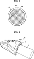
FIG. 4 is a photograph of a sucker used for experiments for verifying advantageous effects of the present invention. - A filter manufacturing apparatus according to an embodiment of the present invention will be described based on the drawings.
- As illustrated in
FIG. 1 , a filter manufacturing apparatus 1 according to the present embodiment includes, as sections for manufacturing a filter rod, atow treating section 2, anadditive feeding section 4, ashaping section 6, and awrapping section 8. - The
tow treating section 2 includes a bale 10 (not illustrated in the drawings) housing, for example, a filter material of cellulose acetate fibers, that is, a tow T.A tow path 12 for the tow T extends from thebale 10. Thetow path 12 includes aprimary banding jet 14, aguide 16, asecondary banding jet 18, a pair ofpretension rollers 20, a pair ofblooming rollers 22, atertiary banding jet 24, aplasticizer feeding unit 26, and a pair ofdelivery rollers 28 sequentially arranged along thepath 12 from thebale 10 side. - When the tow T passes through the
primary banding jet 14, theprimary banding jet 14 jets compressed air from thebale 10 side toward the tow T. The jetted compressed air opens the tow T and appropriately stretches crimps in the tow T. - When the tow T reaches the
guide 16, theguide 16 orients a feeding direction for the tow T toward thesecondary banding jet 18. The tow T subsequently passes through thesecondary banding jet 18. Like theprimary banding jet 14, thesecondary banding jet 18 jets compressed air onto the tow T to further open the tow T to further stretch the crimps in the tow T. The tow T subsequently passes between the pair ofpretension rollers 20. At this time, thepretension rollers 20 presses the opened tow T and applies a predetermined tension to the tow T in cooperation with the pair ofblooming rollers 22, thus further stretching the crimps in the tow T. - When the tow T subsequently passes between the pair of
blooming rollers 22, theblooming rollers 22 divide the opened tow T into a plurality of bundles and feed the bundles toward thetertiary banding jet 24. - When the division bundles of the tow T passes through the
tertiary banding jet 24, the tertiary bandingjet 24 jets compressed air toward the division bundles, and the compressed air opens the division bundles. As a result, the division bundles spread in a width direction of thetow path 12 to form a flat filter web (filter element) WF. The filter web WF subsequently reaches theplasticizer feeding unit 26 provided immediately above atransfer path 30 for the filter web WF. - The
plasticizer feeding unit 26 includes achamber 26A storing a plasticizer (triacetin) and a brush roll (not illustrated in the drawings) that rotates in thechamber 26A. The brush roll rotates in thechamber 26A to splash and make the liquid plasticizer misty. The misty plasticizer is discharged through a discharge port of thechamber 26A and adheres to the filter web WF (plasticizer feeding step). The filter web WF to which the plasticizer has been added is provided with tackiness as a result of a melting effect of the plasticizer on cellulose acetate fibers. - The adjacent cellulose acetate fibers are combined with each other at a plurality of combination points due to the tackiness. These firm combination points of the filter web WF apply, when a filter is later shaped, sufficient hardness to the filter. The filter web WF subsequently passes between the pair of
delivery rollers 28 and is fed from thedelivery rollers 28 to theadditive feeding section 4. - The
additive feeding section 4 includes thetransfer path 30 for the filter web WF, and thetransfer path 30 extends from thedelivery rollers 28 to atrumpet guide 32 of ashaping section 6. - The
transfer path 30 includes a pair ofnip rollers 34 and anadditive feeding unit 36 sequentially arranged from thedelivery roller 28 side. - When the filter web WF passes between the pair of
nip rollers 34, thenip rollers 34 apply a predetermined tension to the filter web WF in cooperation with thetrumpet guide 32 to define thetransfer path 30. Thenip rollers 34 feed the filter web WF toward theadditive feeding unit 36. - The
additive feeding unit 36 is provided immediately above thetransfer path 30 to uniformly spray a granular additive, for example, granular activated carbon AC, onto the filter web WF on thetransfer path 30 to feed the additive to the filter web WF. - The
additive feeding unit 36 according to the present embodiment includes aclassifier 38 classifying the activated carbon AC into coarse grains CG and fine grains FG based on granularity to remove the fine grains FG immediately before feeding the activated carbon AC to the filter web WF. - Specifically, the
additive feeding unit 36 includes afeeder 40 and theclassifier 38 sequentially arranged from an upper side. - The
feeder 40 includes ahopper 40A in which the activated carbon AC is stored and a vibratingconveyor 40B transferring, toward theclassifier 38, the activated carbon AC falling through an outlet formed at a lower end of thehopper 40A. - The
classifier 38 includes ahopper 42 receiving the activated carbon AC conveyed along the vibratingconveyor 40B, abody 44 of theclassifier 38 connected to a lower portion of thehopper 42, adischarge unit 46 connected to a lower portion of thebody 44, a spraying unit (feeding means) 48 connected to a lower portion of thedischarge unit 46, a high-pressure air blower (dispersed air feeding means) 50 connected to a side portion of thedischarge unit 46, and a dust collector (recovery means) 52 and a forced air blower (forced air feeding means) 54 connected to thebody 44. Thebody 44 is shaped like a cylinder for which an up-down direction corresponds to a radial direction. - As illustrated in
FIG. 2 , adispersion chamber 56 and atrapping chamber 58 are adjacently formed in thebody 44. Into thedispersion chamber 56, the activated carbon AC is fed through an outlet formed at a lower end of thehopper 42. Aline 50A extending from the high-pressure air blower 50 is connected to thedischarge unit 46. The high-pressure air blower 50 feeds, to thedispersion chamber 56, dispersed air having pressure increased sequentially through theline 50A and thedischarge unit 46. The dispersed air having flowed into thedischarge unit 46 forms a rising air current, while the dispersed air having flowed into thedispersion chamber 56 forms a swirling air current swirling in the up-down direction to suitably disperse, into particles, the activated carbon AC present in thedispersion chamber 56. - In the
body 44, ascreen 60 is arranged that separates the inside of thebody 44 into thedispersion chamber 56 and the trappingchamber 58. Thescreen 60 is circular wire mesh formed of metal such as stainless steel and including fine meshes. Thescreen 60 has a large mesh size that inhibits the coarse grains CG of the activated carbon AC from passing from thedispersion chamber 56 to the trappingchamber 58 while permitting the fine grains FG of the activated carbon AC to pass from thedispersion chamber 56 to the trappingchamber 58. - As illustrated in
FIG. 1 , thedust collector 52 includes abody 52A, adust collecting material 52B incorporated in thebody 52A, asuction pump 52C connected to thebody 52A above thedust collecting material 52B in thebody 52A, arotary valve 52D provided on an underside of thebody 52A, arecovery box 52E arranged immediately below therotary valve 52D, and aline 52F extending from a position of thebody 52A below thedust collecting material 52B to the trappingchamber 58 of thebody 44. - The
suction pump 52C sucks air in thedispersion chamber 56 in thebody 44 from the trappingchamber 58 side sequentially through thebody 52A, thedust collecting material 52B and theline 52F. Thus, thedust collector 52 recovers, on the trappingchamber 58 side, the fine grains FG having passed through thescreen 60 in thedispersion chamber 56. Thedust collector 52 further recovers the recovered fine grains FG in therecovery box 52E sequentially through theline 52F, thebody 52A and therotary valve 52D. - On the other hand, the coarse grains CG may fall from the
dispersion chamber 56 into thedischarge unit 46 against the swirling air current of the dispersed air and fall from thedischarge unit 46 against the rising air current of the dispersed air. These coarse grains CG are fed to thespraying unit 48 of theclassifier 38. - As illustrated in
FIG. 1 , the sprayingunit 48 includes ahopper 48A in which the coarse grains CG are stored. Thehopper 48A includes an outlet at a lower end of thehopper 48A. The outlet is shaped like a slit that is open downward and that extends in a width direction of the filter web WF. - A spraying
roller 48B is arranged immediately below the outlet of thehopper 48A. The sprayingroller 48B rotates to receive, on an outer peripheral surface of the sprayingroller 48B, the coarse grains CG discharged from thehopper 48A and uniformly sprays the coarse grains CG onto the filter web WF. - Furthermore, as illustrated in
FIG. 2 , theclassifier 38 according to the present embodiment further includes a cleaner 62 that cleans thescreen 60. The cleaner 62 includes anair brush 62A, amotor 62B, and the above-described forcedair blower 54. - ] As also illustrated in
FIG. 3 , theair brush 62A is shaped like a rectangular parallelepiped as viewed from front and arranged to be movable along arear surface 60A of thescreen 60 corresponding to the trappingchamber 58 side. Themotor 62B is coupled to a longitudinal center of theair brush 62A to rotationally drive theair brush 62A along therear surface 60A in the direction of dashed arrows inFIG. 3 . - As illustrated in
FIG. 2 , aline 54A extending from the forcedair blower 54 is in communication with a plurality ofair jetting holes 62C (seeFIG. 3 ) open on therear surface 60A side of theair brush 62A. The forcedair blower 54 jets forced air toward therear surface 60A of thescreen 60 through theair jetting holes 62C. The forced air is intermittently blown against every area of thescreen 60 as a result of rotation of theair brush 62A. This prevents inhibition of the capability of thescreen 60 of recovering the fine grains FG. - As described above, the
classifier 38 according to the present embodiment integrally includes thebody 44 filtering the fine grains FG using thescreen 60 while dispersing the activated carbon AC using the swirling dispersed air, and the above-describedspraying unit 48 feeding the coarse grains CG having fallen against the dispersed air, to the filter web WF via thedischarge unit 46. This implements theadditive feeding unit 36 capable of executing a classifying process of classifying the activated carbon AC into the coarse grains CG and the fine grains FG based on granularity to remove the fine grains FG immediately before feeding the activated carbon AC to the filter web WF (additive feeding step). - As illustrated in
FIG. 1 , the filter web WF to which the coarse grains CG have been fed is transferred toward thetrumpet guide 32 of theshaping section 6, and passes through thetrumpet guide 32. At this time, the filter web WF is squeezed into a rod shape by thetrumpet guide 32 and thus formed into a rod member WR. Thetrumpet guide 32 feeds the rod member WR to thewrapping section 8. - In the
wrapping section 8, a paper web WP is fed onto a stringer tape (not illustrated in the drawings), and the rod member WR fed from thetrumpet guide 32 is laid on top of the paper web WP and bonded to the paper web WP. The rod member WR and the paper web WP subsequently travel over a shaping bed (not illustrated in the drawings) along with the stringer tape, while sequentially passing through a tongue, a wrapping former, a heater, a cooler, and the like (none of which are illustrated in the drawings). A continuous body of a charcoal filter rod is thus formed. The continuous body of the charcoal filter rod is then cut into individual charcoal filter rods using a rotary knife (not illustrated in the drawings) to complete manufacture of filters as final products. - Now, with reference to
FIG. 4 and Tables 1 to 3, for actual filter manufacture to which the present embodiment was applied, results of calculation of a reduction ratio for the amount of dust collected for the scattered fine grains FG will be described. A sucker was used to measure the amount of dust collected for the fine grains FG suspended in the surroundings when an additive feeding unit was used that does not execute a known fine-grain removing process and the amount of dust collected for the fine grains FG suspended in the surroundings when the additive feeding unit according to the present embodiment was used that executes the fine-grain removing process. The reduction ratio for the amount of dust collected was then calculated. - As illustrated in
FIG. 4 , asucker 66 used to collect the fine grains FG in the experiments was formed by utilizing a handy vacuum cleaner and fixedly abutting asuction tube 70 on asuction surface 66A of the vacuum cleaner viafilter paper 68. Specifications of thesucker 66, thesuction tube 70, and thefilter paper 68 and additives (three types) used in the experiments are as follows. -
- suction capability: 10 liters/sec.
- suction surface: circular surface with a diameter of 60 mm
-
- size: tube length of 120 mm, inner diameter of 75 mm
-
- size: length of 100 mm, width of 100 mm, thickness of 0.17 mm
- weight: 0.5 g
- air permeability: 15,000 cu (Coresta unit)
-
- additive A: granular hydrotalcite
- additive B: granular coconut shell activated carbon (in a final manufacturing step, the process of removing the fine grains was executed by washing the filters in water and then drying the filters)
- additive C: granular coconut shell activated carbon (no washing)
- Table 1 indicates results for physical properties of the additives A to C.
[Table 1] Additive A B C Median diameter (D50) um 705 330 337 Particle size distribution on % 0.05 0.00 0.00 1400 um pass % 0.93 - - 850 um pass % 46.99 - - 710 um pass % 50.54 - - 600 um pass % 1.40 0.02 0.07 500 um pass % 0.08 9.32 15.98 425 um pass % 0.01 31.77 33.77 355 um pass % 0.01 33.16 26.52 300 um pass % - 20.57 17.41 250 um pass % - 0.90 1.85 212 um pass % - 4.26 4.41 Apparent density Bulk density g/cm3 0.527 0.397 0.385 Tapped density g/cm3 0.554 0.423 0.414 Compressibility % 4.9 6.2 7.0 Angle of repose ° 31.0 34.2 33.6 Angle of spatula ° 26.1 29.2 28.5 Uniformity 1.2 1.4 1.4 Flowability index 96.0 93.0 93.0 Angle of fall ° 13.5 15.3 17.0 Angle of difference ° 17.5 18.9 16.6 Dispersibility % 8.6 28.9 31.7 Floodability index 75.5 84.5 83.0 Activated carbon test method JIS K1474 7.6 HARDNESS % 97.0 98.2 97.4 Sieving upper limit 1.4400mm Sieving upper limit 0.600mm Sieving upper limit 0.600mm Sieving lower limit 0.355mm Sieving lower limit 0.212mm Sieving lower limit 0.212mm - The medium diameter and the particle size distribution in Table 1 were measured using a dry sieving method. A vertical list of items in Table 1 from the apparent density to the floodability index was measured using Powder Tester, PT-X, Hosokawa Micron Corporation. Furthermore, the activated carbon test method hardness in Table 1 was measured based on JIS K1474 7.6.
- Table 2 below indicates results of two measurement processes for the classifying capability for each of the additives A to C with a weight of approximately 13 to 20 kg when the additives were classified using the
classifier 38 according to the present embodiment.[Table 2] Coarse grains Fine grains Remark on classification stat kg % g % A (first time) 20.25 99.928 14.52 0.072 Acceptable A (second time) 20.25 99.907 18.89 0.093 Acceptable B (first time) 12.98 98.632 7.39 0.056 Acceptable B (second time) 13.04 00.088 7.08 0.054 Acceptable C (first time) 13.02 99.541 14.36 0.110 Acceptable C (second time) 13.02 99.541 15.34 0.117 Acceptable - As is apparent from Table 2, the acceptable classification state was determined regardless of whichever of the additives A to C was classified.
- Table 3 below indicates results of calculation of a reduction ratio of the amount of dust collected according to the present embodiment to the amount of dust collected according to the related art. In this case, during filter manufacture, the
sucker 66 was fixedly installed at a distance of 20 cm from an area where the additive was added to the filter web WF by the additive feeding unit. Thesucker 66 was activated for two minutes, and the amount of dust collected corresponding to the fine grains FG sucked onto thefilter paper 68 was measured. In Table 3, Comparative Examples 1 to 3 represent measurement results obtained when the additives A to C were added using an additive feeding unit according to the related art which does not execute the fine-grain removing process. Examples 1 to 3 represent measurement results obtained when the additives A to C were added using the additive feeding unit according to the present embodiment which executes the fine-grain removing process.[Table 3] Additive Amount of dust collected (mg/2min) Reduction ratio (%) Comparative Example 1 A 51.2 41 Example 1 30.3 Comparative Example 2 B 40.7 73 Example 2 11 Comparative Example 3 C 27.3 67 Example 3 7.8 - As described above, according to the filter manufacturing apparatus 1 in the present embodiment, the
additive feeding unit 36 includes theclassifier 38 classifying the activated carbon AC and removing the fine grains FG immediately before feeding the activated carbon AC to the filter web WF. This allows scatter of the fine grains FG to be suppressed, inhibiting contamination of the filter manufacturing apparatus 1 and surroundings of the apparatus 1. - Furthermore, the
classifier 38 filters the fine grains FG using thescreen 60 to classify the activated carbon AC into the coarse grains CG and the fine grains FG while dispersing the activated carbon AC using the swirling dispersed air. Compared to a case where the activated carbon AC is classified, for example, using a vibrating sieve, the present embodiment allows the activated carbon AC to be efficiently classified into the coarse grains CG and the fine grains FG while inhibiting crushing of particles of the activated carbon AC and generation of new fine grains FG due to mechanical vibration. This is apparent from Table 2. Additionally, as is apparent from Table 3, scatter of the fine grains FG can be significantly reduced during filter manufacture. This allows the filter manufacturing apparatus 1 and the surroundings of the apparatus 1 to be further effectively restrained from being contaminated with the scattered fine grains FG. - Furthermore, the
classifier 38 includes the cleaner 62 that cleans thescreen 60, and the cleaner 62 includes theair brush 62A that jets forced air while rotating. Thus, the forced air allows the activated carbon AC stuck in the meshes of thescreen 60 to be removed to suppress clogging of thescreen 60. This enables further improvement of the capability of thescreen 60 of recovering the fine grains FG. - Furthermore, the forced air is fed from the
air brush 62A to therear surface 60A of thescreen 60 and then forced into thedispersion chamber 56. This promotes further dispersion of particles of the activated carbon AC in thedispersion chamber 56 to allow further improvement of the dispersion capability and dispersion accuracy of theclassifier 38. - Additionally, the filter manufacturing apparatus 1 includes the
plasticizer feeding unit 26. In a case where the plasticizer adheres to the discharge port of thechamber 26A of theplasticizer feeding unit 26, the fine grains FG scattering to the discharge port may adhere to and accumulate on the port and then grow and fall off the port, significantly contaminating the filter manufacturing apparatus 1. - However, in the filter manufacturing apparatus 1 according to the present embodiment, the fine grains FG are removed immediately before the activated carbon AC is fed to the filter web WF, allowing scatter of the fine grains FG to be suppressed, as described above. This allows suppression of generation of deposits of the fine grains FG and contamination of the filter manufacturing apparatus 1 and the surroundings of the apparatus 1 resulting from growth and fall-off of the deposits as described above.
- The embodiment of the present invention has been described. The present invention is not limited to this but various changes may be made to the embodiment without departing the spirits of the present invention.
- For example, the
classifier 38 described above in the embodiment is not strictly limited to the above-described configuration. For example, the dispersed air flowing into thedispersion chamber 56 forms a swirling air current swirling in the up-down direction. However, the present invention is not limited to this, and the dispersed air may form a swirling air current in the horizontal direction. - Furthermore, in the above-described embodiment, the filter manufacturing apparatus 1 feeds the activated carbon AC to the flat filter web WF shaped from the tow T to form a filter. However, the present invention is not limited to this, and the present invention is applicable to formation of a filter including feeding the activated carbon AC among filter portions (filter elements) formed by cutting a filter rod.
- Furthermore, the additive usable for the filter manufacturing apparatus 1 according to the present embodiment is not limited to the above-described activated carbon AC or hydrotalcite. The present invention allows assumption of various additives for modifying components of mainstream smoke of a smoking article or characterizing appearance of the smoking article, for example, menthol crystals, perfume capsules, sepiolite, or silica granules.
-
- 1 Filter manufacturing apparatus
- 26 Plasticizer feeding unit
- 30 Transfer path
- 36 Additive feeding unit
- 38 Classifier
- 48 Spraying unit (feeding means)
- 50 High-pressure air blower (dispersed air feeding means)
- 52 Dust collector (recovery means)
- 54 Forced air blower (forced air feeding means) 56 Dispersion chamber
- 58 Trapping chamber
- 60 Screen
- 60A Rear surface
- 62 Cleaner
- 62A Air brush
- 62B Motor
- 62C Air jetting hole
- AC Activated carbon (additive)
- CG Coarse grain
- FG Fine grain
- WF Filter web (filter element)
Claims (8)
- A filter manufacturing apparatus comprising:a transfer path through which filter elements for a smoking article is transferred; andan additive feeding unit provided immediately above the transfer path to feed a granular additive to each of the filter elements or among the filter elements on the transfer path, whereinthe additive feeding unit includes a classifier classifying the additive into coarse grains and fine grains based on granularity to remove the fine grains immediately before feeding the additive to each of the filter elements or among the filter elements.
- The filter manufacturing apparatus according to claim 1, wherein the classifier filters the fine grains while dispersing the additive using swirling dispersed air, and feeds, to each of the filter elements or among the filter elements, the coarse grains having fallen against the dispersed air.
- The filter manufacturing apparatus according to claim 2, wherein
the classifier includes:a dispersion chamber into which the additive is introduced;dispersed air feeding means feeding the dispersed air into the dispersion chamber;a screen defining a trapping chamber adjacent to the dispersion chamber to inhibit passage of the coarse grains from the dispersion chamber to the trapping chamber while permitting passage of the fine grains;recovery means for sucking air in the dispersion chamber from the trapping chamber side to recover, through the trapping chamber, the fine grains having passed from the dispersion chamber through the screen; andfeeding means for receiving, in the dispersion chamber, the coarse grains having fallen against the dispersed air and feeding the coarse grains to each of the filter elements or among the filter elements. - The filter manufacturing apparatus according to claim 3, wherein
the classifier further includes:a cleaner cleaning the screen, andthe cleaner includes:an air brush arranged to be movable along a rear surface of the screen corresponding to the trapping chamber;a motor coupled to a longitudinal center of the air brush to rotationally drive the air brush along the rear surface;forced air feeding means for feeding forced air from the air brush toward the rear surface; anda plurality of air jetting holes open in the air brush and through which the forced air is jetted. - The filter manufacturing apparatus according to any one of claims 1 to 4, further comprising:
a plasticizer feeding unit feeding a plasticizer to each of the filter elements on the transfer path. - A filter manufacturing method comprising an additive feeding step of feeding, during transfer of filter elements for a smoking article along a transfer path, a granular additive from immediately above the transfer path to each of the filter elements or among the filter elements, wherein
the additive feeding step comprises a classifying process of classifying the additive into coarse grains and fine grains based on granularity to remove the fine grains immediately before feeding the additive to each of the filter elements or among the filter elements. - The filter manufacturing method according to claim 6, wherein
the classifying process includes filtering the fine grains while dispersing the additive using swirling dispersed air and feeding, to each of the filter elements or among the filter elements, the coarse grains having fallen against the dispersed air. - The filter manufacturing method according to claim 6 or 7, further comprising a plasticizer feeding step of feeding a plasticizer to each of the filter elements on the transfer path.
Priority Applications (1)
| Application Number | Priority Date | Filing Date | Title |
|---|---|---|---|
| PL16910479T PL3488711T3 (en) | 2016-07-26 | 2016-07-26 | Filter manufacturing device and filter manufacturing method |
Applications Claiming Priority (1)
| Application Number | Priority Date | Filing Date | Title |
|---|---|---|---|
| PCT/JP2016/071864 WO2018020576A1 (en) | 2016-07-26 | 2016-07-26 | Filter manufacturing device and filter manufacturing method |
Publications (3)
| Publication Number | Publication Date |
|---|---|
| EP3488711A1 true EP3488711A1 (en) | 2019-05-29 |
| EP3488711A4 EP3488711A4 (en) | 2020-03-18 |
| EP3488711B1 EP3488711B1 (en) | 2021-03-10 |
Family
ID=61016926
Family Applications (1)
| Application Number | Title | Priority Date | Filing Date |
|---|---|---|---|
| EP16910479.1A Active EP3488711B1 (en) | 2016-07-26 | 2016-07-26 | Filter manufacturing device and filter manufacturing method |
Country Status (5)
| Country | Link |
|---|---|
| EP (1) | EP3488711B1 (en) |
| JP (1) | JP6754837B2 (en) |
| PL (1) | PL3488711T3 (en) |
| TW (1) | TWI629940B (en) |
| WO (1) | WO2018020576A1 (en) |
Families Citing this family (1)
| Publication number | Priority date | Publication date | Assignee | Title |
|---|---|---|---|---|
| CN114680375A (en) * | 2022-04-11 | 2022-07-01 | 云南中烟工业有限责任公司 | One-step forming device and one-step forming method for filter stick with binary composite structure |
Family Cites Families (10)
| Publication number | Priority date | Publication date | Assignee | Title |
|---|---|---|---|---|
| US3837264A (en) * | 1973-05-07 | 1974-09-24 | Brown & Williamson Tobacco Corp | Intermittent process for manufacture of a multiple filter rod having spaced pockets containing particulate material |
| JPH06327455A (en) * | 1993-05-26 | 1994-11-29 | Japan Tobacco Inc | Tobacco filter production unit having netty guide pipe |
| TW241198B (en) * | 1993-09-06 | 1995-02-21 | Daicel Chem | A tobacco filter material and a method of producing the same |
| US7479098B2 (en) * | 2005-09-23 | 2009-01-20 | R. J. Reynolds Tobacco Company | Equipment for insertion of objects into smoking articles |
| KR100984681B1 (en) * | 2008-04-18 | 2010-10-01 | 주식회사 케이티앤지 | Cigarette Filter Added Herbal Granules and Tobacco |
| JP4889663B2 (en) * | 2008-02-07 | 2012-03-07 | 株式会社セイシン企業 | Airflow screening method and apparatus |
| WO2011070639A1 (en) * | 2009-12-07 | 2011-06-16 | 日本たばこ産業株式会社 | Powder adding device and adding method thereof |
| WO2011117982A1 (en) * | 2010-03-24 | 2011-09-29 | 日本たばこ産業株式会社 | Powder-adding device and adding method thereof |
| EA033296B1 (en) * | 2014-07-18 | 2019-09-30 | Джапан Тобакко Инк. | Apparatus and method for producing cigarette filter |
| JP2017038894A (en) * | 2015-08-23 | 2017-02-23 | 日本電産コパル株式会社 | Cleaning robot |
-
2016
- 2016-07-26 EP EP16910479.1A patent/EP3488711B1/en active Active
- 2016-07-26 PL PL16910479T patent/PL3488711T3/en unknown
- 2016-07-26 WO PCT/JP2016/071864 patent/WO2018020576A1/en not_active Ceased
- 2016-07-26 JP JP2018530232A patent/JP6754837B2/en not_active Expired - Fee Related
- 2016-08-25 TW TW105127235A patent/TWI629940B/en not_active IP Right Cessation
Also Published As
| Publication number | Publication date |
|---|---|
| TWI629940B (en) | 2018-07-21 |
| EP3488711B1 (en) | 2021-03-10 |
| JP6754837B2 (en) | 2020-09-16 |
| JPWO2018020576A1 (en) | 2019-04-11 |
| WO2018020576A1 (en) | 2018-02-01 |
| EP3488711A4 (en) | 2020-03-18 |
| PL3488711T3 (en) | 2021-06-28 |
| TW201803465A (en) | 2018-02-01 |
Similar Documents
| Publication | Publication Date | Title |
|---|---|---|
| TWI653097B (en) | Manufacturing device for purifying polycrystalline crucible broken pieces and method for producing and purifying polycrystalline crucible broken pieces by using the same | |
| US6371126B1 (en) | Tobacco recovery system | |
| EP3208236B1 (en) | Polycrystalline silicon fragment, method for manufacturing polycrystalline silicon fragment, and polycrystalline silicon block fracture device | |
| JP5300511B2 (en) | System for removing impurities in cut tobacco collected from defective cigarettes | |
| CN102119783A (en) | Multifunctional tobacco leaf air separation impurity removing method and equipment | |
| CN201911279U (en) | Multifunctional tobacco leaf winnowing and impurity removing equipment | |
| EP3488711B1 (en) | Filter manufacturing device and filter manufacturing method | |
| JP4822462B2 (en) | Cigarette production machine | |
| DE2506839A1 (en) | METHOD AND DEVICE FOR FORMING A TOBACCO FLOW | |
| CN102700929A (en) | Uniform feeding device with vibrating screen | |
| CN112403682A (en) | White tea electrostatic impurity removal and dust reduction device | |
| CN101953509A (en) | Comprehensive impurity eliminating and screening equipment for tobacco stems | |
| CN104013099A (en) | Cleaning of a machine for the tobacco processing industry | |
| JPS63188376A (en) | Method and apparatus for feeding tobacco to tobacco manufacturing machine | |
| CN212139281U (en) | Threshing and discharging sorting vibrating screen with hemp removing function | |
| EP3232827B1 (en) | Tobacco rod maker with tobacco return | |
| US20040060570A1 (en) | Method of and apparatus for making a tobacco rod | |
| JP5524710B2 (en) | Preparation of filter strips for the tobacco processing industry | |
| CN103521443A (en) | Blowing type device for recovering cut tobacco in rejected stem slivers | |
| CN203862529U (en) | Dust removing device of tobacco cutter | |
| CN103519346A (en) | Multistage separating type recovery device for cut tobaccos in stick stem removal objects | |
| CN105692126A (en) | Cleaning device for air-cushioned belt conveyor | |
| CN211677923U (en) | Cosmetics three-roller rubbing crusher | |
| JP3430266B2 (en) | Powder addition device for noodle strings | |
| CN221166848U (en) | Silicon seed crystal preparation system |
Legal Events
| Date | Code | Title | Description |
|---|---|---|---|
| STAA | Information on the status of an ep patent application or granted ep patent |
Free format text: STATUS: THE INTERNATIONAL PUBLICATION HAS BEEN MADE |
|
| PUAI | Public reference made under article 153(3) epc to a published international application that has entered the european phase |
Free format text: ORIGINAL CODE: 0009012 |
|
| STAA | Information on the status of an ep patent application or granted ep patent |
Free format text: STATUS: REQUEST FOR EXAMINATION WAS MADE |
|
| 17P | Request for examination filed |
Effective date: 20190220 |
|
| AK | Designated contracting states |
Kind code of ref document: A1 Designated state(s): AL AT BE BG CH CY CZ DE DK EE ES FI FR GB GR HR HU IE IS IT LI LT LU LV MC MK MT NL NO PL PT RO RS SE SI SK SM TR |
|
| AX | Request for extension of the european patent |
Extension state: BA ME |
|
| DAV | Request for validation of the european patent (deleted) | ||
| DAX | Request for extension of the european patent (deleted) | ||
| A4 | Supplementary search report drawn up and despatched |
Effective date: 20200214 |
|
| RIC1 | Information provided on ipc code assigned before grant |
Ipc: A24D 3/02 20060101AFI20200210BHEP |
|
| GRAP | Despatch of communication of intention to grant a patent |
Free format text: ORIGINAL CODE: EPIDOSNIGR1 |
|
| STAA | Information on the status of an ep patent application or granted ep patent |
Free format text: STATUS: GRANT OF PATENT IS INTENDED |
|
| INTG | Intention to grant announced |
Effective date: 20200928 |
|
| GRAS | Grant fee paid |
Free format text: ORIGINAL CODE: EPIDOSNIGR3 |
|
| GRAA | (expected) grant |
Free format text: ORIGINAL CODE: 0009210 |
|
| STAA | Information on the status of an ep patent application or granted ep patent |
Free format text: STATUS: THE PATENT HAS BEEN GRANTED |
|
| AK | Designated contracting states |
Kind code of ref document: B1 Designated state(s): AL AT BE BG CH CY CZ DE DK EE ES FI FR GB GR HR HU IE IS IT LI LT LU LV MC MK MT NL NO PL PT RO RS SE SI SK SM TR |
|
| REG | Reference to a national code |
Ref country code: GB Ref legal event code: FG4D |
|
| REG | Reference to a national code |
Ref country code: AT Ref legal event code: REF Ref document number: 1368788 Country of ref document: AT Kind code of ref document: T Effective date: 20210315 Ref country code: CH Ref legal event code: EP |
|
| REG | Reference to a national code |
Ref country code: IE Ref legal event code: FG4D |
|
| REG | Reference to a national code |
Ref country code: DE Ref legal event code: R096 Ref document number: 602016054269 Country of ref document: DE |
|
| REG | Reference to a national code |
Ref country code: LT Ref legal event code: MG9D |
|
| PG25 | Lapsed in a contracting state [announced via postgrant information from national office to epo] |
Ref country code: LT Free format text: LAPSE BECAUSE OF FAILURE TO SUBMIT A TRANSLATION OF THE DESCRIPTION OR TO PAY THE FEE WITHIN THE PRESCRIBED TIME-LIMIT Effective date: 20210310 Ref country code: BG Free format text: LAPSE BECAUSE OF FAILURE TO SUBMIT A TRANSLATION OF THE DESCRIPTION OR TO PAY THE FEE WITHIN THE PRESCRIBED TIME-LIMIT Effective date: 20210610 Ref country code: GR Free format text: LAPSE BECAUSE OF FAILURE TO SUBMIT A TRANSLATION OF THE DESCRIPTION OR TO PAY THE FEE WITHIN THE PRESCRIBED TIME-LIMIT Effective date: 20210611 Ref country code: FI Free format text: LAPSE BECAUSE OF FAILURE TO SUBMIT A TRANSLATION OF THE DESCRIPTION OR TO PAY THE FEE WITHIN THE PRESCRIBED TIME-LIMIT Effective date: 20210310 Ref country code: HR Free format text: LAPSE BECAUSE OF FAILURE TO SUBMIT A TRANSLATION OF THE DESCRIPTION OR TO PAY THE FEE WITHIN THE PRESCRIBED TIME-LIMIT Effective date: 20210310 Ref country code: NO Free format text: LAPSE BECAUSE OF FAILURE TO SUBMIT A TRANSLATION OF THE DESCRIPTION OR TO PAY THE FEE WITHIN THE PRESCRIBED TIME-LIMIT Effective date: 20210610 |
|
| REG | Reference to a national code |
Ref country code: AT Ref legal event code: MK05 Ref document number: 1368788 Country of ref document: AT Kind code of ref document: T Effective date: 20210310 |
|
| REG | Reference to a national code |
Ref country code: NL Ref legal event code: MP Effective date: 20210310 |
|
| PG25 | Lapsed in a contracting state [announced via postgrant information from national office to epo] |
Ref country code: SE Free format text: LAPSE BECAUSE OF FAILURE TO SUBMIT A TRANSLATION OF THE DESCRIPTION OR TO PAY THE FEE WITHIN THE PRESCRIBED TIME-LIMIT Effective date: 20210310 Ref country code: LV Free format text: LAPSE BECAUSE OF FAILURE TO SUBMIT A TRANSLATION OF THE DESCRIPTION OR TO PAY THE FEE WITHIN THE PRESCRIBED TIME-LIMIT Effective date: 20210310 Ref country code: RS Free format text: LAPSE BECAUSE OF FAILURE TO SUBMIT A TRANSLATION OF THE DESCRIPTION OR TO PAY THE FEE WITHIN THE PRESCRIBED TIME-LIMIT Effective date: 20210310 |
|
| PG25 | Lapsed in a contracting state [announced via postgrant information from national office to epo] |
Ref country code: NL Free format text: LAPSE BECAUSE OF FAILURE TO SUBMIT A TRANSLATION OF THE DESCRIPTION OR TO PAY THE FEE WITHIN THE PRESCRIBED TIME-LIMIT Effective date: 20210310 |
|
| PG25 | Lapsed in a contracting state [announced via postgrant information from national office to epo] |
Ref country code: SM Free format text: LAPSE BECAUSE OF FAILURE TO SUBMIT A TRANSLATION OF THE DESCRIPTION OR TO PAY THE FEE WITHIN THE PRESCRIBED TIME-LIMIT Effective date: 20210310 Ref country code: AT Free format text: LAPSE BECAUSE OF FAILURE TO SUBMIT A TRANSLATION OF THE DESCRIPTION OR TO PAY THE FEE WITHIN THE PRESCRIBED TIME-LIMIT Effective date: 20210310 Ref country code: EE Free format text: LAPSE BECAUSE OF FAILURE TO SUBMIT A TRANSLATION OF THE DESCRIPTION OR TO PAY THE FEE WITHIN THE PRESCRIBED TIME-LIMIT Effective date: 20210310 Ref country code: CZ Free format text: LAPSE BECAUSE OF FAILURE TO SUBMIT A TRANSLATION OF THE DESCRIPTION OR TO PAY THE FEE WITHIN THE PRESCRIBED TIME-LIMIT Effective date: 20210310 |
|
| PG25 | Lapsed in a contracting state [announced via postgrant information from national office to epo] |
Ref country code: SK Free format text: LAPSE BECAUSE OF FAILURE TO SUBMIT A TRANSLATION OF THE DESCRIPTION OR TO PAY THE FEE WITHIN THE PRESCRIBED TIME-LIMIT Effective date: 20210310 Ref country code: RO Free format text: LAPSE BECAUSE OF FAILURE TO SUBMIT A TRANSLATION OF THE DESCRIPTION OR TO PAY THE FEE WITHIN THE PRESCRIBED TIME-LIMIT Effective date: 20210310 Ref country code: PT Free format text: LAPSE BECAUSE OF FAILURE TO SUBMIT A TRANSLATION OF THE DESCRIPTION OR TO PAY THE FEE WITHIN THE PRESCRIBED TIME-LIMIT Effective date: 20210712 Ref country code: IS Free format text: LAPSE BECAUSE OF FAILURE TO SUBMIT A TRANSLATION OF THE DESCRIPTION OR TO PAY THE FEE WITHIN THE PRESCRIBED TIME-LIMIT Effective date: 20210710 |
|
| REG | Reference to a national code |
Ref country code: DE Ref legal event code: R097 Ref document number: 602016054269 Country of ref document: DE |
|
| PLBE | No opposition filed within time limit |
Free format text: ORIGINAL CODE: 0009261 |
|
| STAA | Information on the status of an ep patent application or granted ep patent |
Free format text: STATUS: NO OPPOSITION FILED WITHIN TIME LIMIT |
|
| PG25 | Lapsed in a contracting state [announced via postgrant information from national office to epo] |
Ref country code: DK Free format text: LAPSE BECAUSE OF FAILURE TO SUBMIT A TRANSLATION OF THE DESCRIPTION OR TO PAY THE FEE WITHIN THE PRESCRIBED TIME-LIMIT Effective date: 20210310 Ref country code: AL Free format text: LAPSE BECAUSE OF FAILURE TO SUBMIT A TRANSLATION OF THE DESCRIPTION OR TO PAY THE FEE WITHIN THE PRESCRIBED TIME-LIMIT Effective date: 20210310 Ref country code: ES Free format text: LAPSE BECAUSE OF FAILURE TO SUBMIT A TRANSLATION OF THE DESCRIPTION OR TO PAY THE FEE WITHIN THE PRESCRIBED TIME-LIMIT Effective date: 20210310 |
|
| 26N | No opposition filed |
Effective date: 20211213 |
|
| PG25 | Lapsed in a contracting state [announced via postgrant information from national office to epo] |
Ref country code: SI Free format text: LAPSE BECAUSE OF FAILURE TO SUBMIT A TRANSLATION OF THE DESCRIPTION OR TO PAY THE FEE WITHIN THE PRESCRIBED TIME-LIMIT Effective date: 20210310 |
|
| REG | Reference to a national code |
Ref country code: CH Ref legal event code: PL |
|
| PG25 | Lapsed in a contracting state [announced via postgrant information from national office to epo] |
Ref country code: MC Free format text: LAPSE BECAUSE OF FAILURE TO SUBMIT A TRANSLATION OF THE DESCRIPTION OR TO PAY THE FEE WITHIN THE PRESCRIBED TIME-LIMIT Effective date: 20210310 |
|
| REG | Reference to a national code |
Ref country code: BE Ref legal event code: MM Effective date: 20210731 |
|
| PG25 | Lapsed in a contracting state [announced via postgrant information from national office to epo] |
Ref country code: LI Free format text: LAPSE BECAUSE OF NON-PAYMENT OF DUE FEES Effective date: 20210731 Ref country code: CH Free format text: LAPSE BECAUSE OF NON-PAYMENT OF DUE FEES Effective date: 20210731 |
|
| PG25 | Lapsed in a contracting state [announced via postgrant information from national office to epo] |
Ref country code: IS Free format text: LAPSE BECAUSE OF FAILURE TO SUBMIT A TRANSLATION OF THE DESCRIPTION OR TO PAY THE FEE WITHIN THE PRESCRIBED TIME-LIMIT Effective date: 20210710 Ref country code: LU Free format text: LAPSE BECAUSE OF NON-PAYMENT OF DUE FEES Effective date: 20210726 |
|
| PG25 | Lapsed in a contracting state [announced via postgrant information from national office to epo] |
Ref country code: IE Free format text: LAPSE BECAUSE OF NON-PAYMENT OF DUE FEES Effective date: 20210726 Ref country code: BE Free format text: LAPSE BECAUSE OF NON-PAYMENT OF DUE FEES Effective date: 20210731 |
|
| PG25 | Lapsed in a contracting state [announced via postgrant information from national office to epo] |
Ref country code: CY Free format text: LAPSE BECAUSE OF FAILURE TO SUBMIT A TRANSLATION OF THE DESCRIPTION OR TO PAY THE FEE WITHIN THE PRESCRIBED TIME-LIMIT Effective date: 20210310 |
|
| P01 | Opt-out of the competence of the unified patent court (upc) registered |
Effective date: 20230530 |
|
| PG25 | Lapsed in a contracting state [announced via postgrant information from national office to epo] |
Ref country code: HU Free format text: LAPSE BECAUSE OF FAILURE TO SUBMIT A TRANSLATION OF THE DESCRIPTION OR TO PAY THE FEE WITHIN THE PRESCRIBED TIME-LIMIT; INVALID AB INITIO Effective date: 20160726 |
|
| PG25 | Lapsed in a contracting state [announced via postgrant information from national office to epo] |
Ref country code: MK Free format text: LAPSE BECAUSE OF FAILURE TO SUBMIT A TRANSLATION OF THE DESCRIPTION OR TO PAY THE FEE WITHIN THE PRESCRIBED TIME-LIMIT Effective date: 20210310 |
|
| PG25 | Lapsed in a contracting state [announced via postgrant information from national office to epo] |
Ref country code: MT Free format text: LAPSE BECAUSE OF FAILURE TO SUBMIT A TRANSLATION OF THE DESCRIPTION OR TO PAY THE FEE WITHIN THE PRESCRIBED TIME-LIMIT Effective date: 20210310 |
|
| PGFP | Annual fee paid to national office [announced via postgrant information from national office to epo] |
Ref country code: PL Payment date: 20240722 Year of fee payment: 9 |
|
| PGFP | Annual fee paid to national office [announced via postgrant information from national office to epo] |
Ref country code: DE Payment date: 20250722 Year of fee payment: 10 |
|
| PGFP | Annual fee paid to national office [announced via postgrant information from national office to epo] |
Ref country code: IT Payment date: 20250724 Year of fee payment: 10 |
|
| PGFP | Annual fee paid to national office [announced via postgrant information from national office to epo] |
Ref country code: GB Payment date: 20250722 Year of fee payment: 10 |
|
| PGFP | Annual fee paid to national office [announced via postgrant information from national office to epo] |
Ref country code: FR Payment date: 20250725 Year of fee payment: 10 |
|
| PG25 | Lapsed in a contracting state [announced via postgrant information from national office to epo] |
Ref country code: TR Free format text: LAPSE BECAUSE OF FAILURE TO SUBMIT A TRANSLATION OF THE DESCRIPTION OR TO PAY THE FEE WITHIN THE PRESCRIBED TIME-LIMIT Effective date: 20210310 |