EP3488692B1 - Rückgewinnungsplatte von pflanzenschutzmitteln, und sprühgerät - Google Patents
Rückgewinnungsplatte von pflanzenschutzmitteln, und sprühgerät Download PDFInfo
- Publication number
- EP3488692B1 EP3488692B1 EP18208269.3A EP18208269A EP3488692B1 EP 3488692 B1 EP3488692 B1 EP 3488692B1 EP 18208269 A EP18208269 A EP 18208269A EP 3488692 B1 EP3488692 B1 EP 3488692B1
- Authority
- EP
- European Patent Office
- Prior art keywords
- panel
- recovering
- fins
- machine
- recovery
- Prior art date
- Legal status (The legal status is an assumption and is not a legal conclusion. Google has not performed a legal analysis and makes no representation as to the accuracy of the status listed.)
- Active
Links
Images



Classifications
-
- A—HUMAN NECESSITIES
- A01—AGRICULTURE; FORESTRY; ANIMAL HUSBANDRY; HUNTING; TRAPPING; FISHING
- A01C—PLANTING; SOWING; FERTILISING
- A01C23/00—Distributing devices specially adapted for liquid manure or other fertilising liquid, including ammonia, e.g. transport tanks or sprinkling wagons
- A01C23/04—Distributing under pressure; Distributing mud; Adaptation of watering systems for fertilising-liquids
- A01C23/047—Spraying of liquid fertilisers
-
- A—HUMAN NECESSITIES
- A01—AGRICULTURE; FORESTRY; ANIMAL HUSBANDRY; HUNTING; TRAPPING; FISHING
- A01M—CATCHING, TRAPPING OR SCARING OF ANIMALS; APPARATUS FOR THE DESTRUCTION OF NOXIOUS ANIMALS OR NOXIOUS PLANTS
- A01M7/00—Special adaptations or arrangements of liquid-spraying apparatus for purposes covered by this subclass
- A01M7/0003—Atomisers or mist blowers
- A01M7/0014—Field atomisers, e.g. orchard atomisers, self-propelled, drawn or tractor-mounted
-
- A—HUMAN NECESSITIES
- A01—AGRICULTURE; FORESTRY; ANIMAL HUSBANDRY; HUNTING; TRAPPING; FISHING
- A01M—CATCHING, TRAPPING OR SCARING OF ANIMALS; APPARATUS FOR THE DESTRUCTION OF NOXIOUS ANIMALS OR NOXIOUS PLANTS
- A01M7/00—Special adaptations or arrangements of liquid-spraying apparatus for purposes covered by this subclass
- A01M7/005—Special arrangements or adaptations of the spraying or distributing parts, e.g. adaptations or mounting of the spray booms, mounting of the nozzles, protection shields
- A01M7/0064—Protection shields
- A01M7/0067—Protection shields with recovering of liquids
-
- B—PERFORMING OPERATIONS; TRANSPORTING
- B05—SPRAYING OR ATOMISING IN GENERAL; APPLYING FLUENT MATERIALS TO SURFACES, IN GENERAL
- B05B—SPRAYING APPARATUS; ATOMISING APPARATUS; NOZZLES
- B05B14/00—Arrangements for collecting, re-using or eliminating excess spraying material
Definitions
- the invention relates to a phytosanitary product recovery panel, as well as a machine for spraying phytosanitary product on a viticultural or arboricultural crop.
- recuperator panels which make it possible to partially recover the product that does not remain on the vine, have been created.
- the rebound phenomenon of the air projected on the bottom of the panel leads to lateral dispersions of air laden with phytosanitary product which adversely affects the rate of recovery of these recovery panels.
- the invention intends to remedy by proposing a new recuperator panel allowing an increased rate of recovery of phytosanitary product compared to the materials of the prior art.
- the invention relates to a phytosanitary product recovery panel, comprising the characteristics of claim 1.
- the flow of air does not cause a rebound effect on the panel and is guided, which avoids dispersion of the phytosanitary product around the panel and improves recovery.
- the invention also relates to a machine for spraying phytosanitary product in a wine crop, comprising at least one spraying device comprising at least one nozzle for spraying phytosanitary product adapted to spray the phytosanitary product on a first side of a vine, and at least one recuperator panel located on an opposite side of this vine facing the spray nozzle.
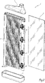
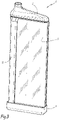
- the figure 1 represents a recovery panel 2 for phytosanitary product, comprising a recovery surface 4 extending along a main plane P, and a recovery tank 6 located on one edge of the recovery surface 4 so as to receive the phytosanitary product by flow on the recovery surface 4.
- the plan principal P is represented vertical. It can change orientation depending on the movement of a spraying machine 10 on which the recuperator panel 2 is installed.
- the machine 10 for spraying phytosanitary product in a wine crop comprises at least one spraying device 12, also called downpipe, comprising at least one projection nozzle 14 for phytosanitary product adapted to project the phytosanitary product onto a first side of a vine V, and at least one recovery panel 2 located on an opposite side of this vine V opposite the spray nozzle 14.
- the machine 10 moves between rows of vines V in a direction of advance X.
- the machine 10 can also be adapted to the treatment of tree crops.
- the nozzles 14 are combined with air diffusers which blow a flow of air F, which carries the phytosanitary product dispersed in the form of droplets towards the vines.
- An air inlet duct 3 is provided on an upper part of the panel 2.
- the devices 12 are combined with the recuperator panels 2.
- a first spray device 12A is provided on a first recuperator panel 2A and adapted to project phytosanitary product towards a second recuperator panel 2B located opposite with respect to the vine V.
- a second spraying device 12B provided on the second recuperator panel 2B and adapted to project phytosanitary product in the direction of the first recuperator panel 2A.
- the spray device 12A is located on the front side 16 of the panel 2A, relative to the direction of advance X of the machine 10, and the spray device 12B is located on the rear side 18 of the panel 2B, relative to the direction in advance X.
- the spray devices 12A and 12B are all arranged on the front side, or on the rear side. So as we can see on the figure 8 the spray devices 12A and 12B are arranged forward of the panels 2A and 2B.
- the blowing directions of the nozzles 14 can be modified and are oriented with respect to the main plane P.
- the blowing direction of the spray device 12A located at the front, is different from the blowing direction of the spray device 12B, located at the rear.
- the direction of the airflow F from the spraying device 12A forms an angle ⁇ 1 with respect to a direction perpendicular to the direction of advance X.
- the angle ⁇ 1 is between -15° and 15°, preferably between 0 and 10°, even more preferably equal to 5°.
- the direction of the airflow F from the spraying device 12B forms an angle ⁇ 2 with respect to a direction perpendicular to the direction of advance X.
- the angle ⁇ 2 is between 0° and 45°, preferably between 0 and 25 °, even more preferably equal to 15°.
- the positive values of the examples of angles given correspond to directions of air flow F directed rearward with respect to the direction of advance X of the machine 10.
- the panels 2 and the associated spraying devices 12 are carried by a supporting structure, not shown, and the machine 10 can be self-propelled, mounted on a vehicle, or else towed.
- the recovery surface 4 is formed by a plurality of fins 40 spaced apart from each other so that the air flow F can cross the recovery surface 4 by passing between the fins 40.
- the air carrying the droplets of phytosanitary product passes through a perforated surface, in which the air is guided, and the flow of air broken to reduce its energy and its dispersion.
- the fins 40 are inclined with respect to the main plane P according to an angie ⁇ so as to form a continuous obstacle in a direction perpendicular to the main plane P. As can be seen on the figure 4 , there is no space between the fins 40, so that the maximum phytosanitary product is recovered, while allowing air to pass. In general, the projected surface of the fins 40 along a direction parallel to the direction of the air flow F is continuous.
- the fins 40 can be orientable with respect to the plane P.
- the fins 40 can be rotatable around a longitudinal axis Z40 parallel to the direction Z and to the plane P, in such a way that the angle ⁇ can be amended.
- the orientation of the fins 40 is done manually or automatically, individually or in series.
- the fins 40 may have a non-rectilinear profile, as is visible on the figure 5 and 6 .
- the fins 40 have a curved shape.
- the fins 40 may have angles.
- the non-rectilinear shape makes it possible to guide the flow of air in a desired direction.
- the fins can be solid or perforated.
- the orientation of the fins 40 may be different over the width of the panels 2.
- the fins 40 located on the side of the front of the machine may have an angle with respect to the direction of advance X different with respect to the fins located on the rear side of the machine.
- the panels 2 can be inclined with respect to the vines V.
- the panels can present an open angle in the direction of the advance of the machine.
- the panels then have a funnel or "V" shape, as can be seen in the figure 8 .
- the panels 2A and 2B can form an angle ⁇ with respect to the direction of advance X.
- the panel 2 comprises an element 8 permeable to the passage of air, or net, the area of which is substantially equal to that of the recovery surface 4, and extending along the main plane P.
- the net 8 is located in rear of the recovery surface 4 in such a way that the air flow F passing through the panel 2 passes first through the fins 40 then through the net 8.
- the net 8 is called "rear net” .
- the rear net 8 can have mesh widths of between 0.5 and 2.5 mm 2 , preferably 1 mm 2 .
- the net can be characterized in Mesh and include values between 7 and 35.
- mesh an air-permeable, perforated element.
- the net may in particular be in the form of a mesh of stainless steel, plastic, plastic injected in one piece.
- the rear net 8 is placed against the fins 40 in a variant not shown, the rear net 8 can be moved away from the fins 40 by a distance of up to 150 mm, preferably between 10 and 20 mm.
- a second element 20 permeable to the passage of air can also be provided in front of the recovery surface 4.
- This element 20, which will be called “front net” can be in the form of a net having meshes of width greater than the width of the meshes of the rear net 8.
- the front net 20 preferably has meshes with a dimension of the order of 2.5 to 5 mm 2 .
- the objective of the front net 20 is to filter, by capturing plant elements before they enter the fins 40, while the rear net 8 aims to let the air pass while breaking the air flow F, and to recover the residual droplets carried by the air flow F.
- the panel 2 has a substantially vertical longitudinal direction Z, and a transverse direction substantially parallel to the ground and aligned with the direction of advance X of the machine 10.
- the fins 40 extend in the longitudinal direction Z of the panel 2.
- the width of the fins 40 is defined as being their dimension in a direction perpendicular to the longitudinal direction Z.
- the fins 40 can be oriented differently with respect to the longitudinal direction Z.
- the width of the fins 40 can be variable between the front side and the rear side of the panels 2A and 2B.
- the fins arranged on the front of the panel 2A or 2B being narrower than the fins arranged on the rear part of the panel 2A or 2B.
- the fins 40 arranged on the rear may have an equivalent width but a positioning on the panel which shifts the fins in the direction of the opposite panel (or towards the corresponding device 12).
- the recuperator panel 2 may comprise two planes of fins on either side of a central plane Pc, forming two recovery surfaces 4 making it possible to recover product on two opposite faces.
- the two fin planes can be separated by nets, or by a partition, or by a combination of nets and partitions.
- the orientation ⁇ of the fins 40 can be controlled by a servo according to the orientation of the nozzles of the devices 12 and/or the speed of advance of the machine 10.
- the servo can also be a function of the speed of the wind surrounding. This servo-control can be performed using air fin orientation sensors 40 and an electronic control unit.
- the forward speed of the machine can be between 5 and 10 km/h.
- panel 2 forms an assembly that is permeable to air, that is to say that air can pass through it from one side to the other, and there is no rebound phenomenon. on flat surfaces opposite to the direction of the airflow.
- the blown air flow F can have a width of the order of 30 cm on its arrival on the panel 2.
Landscapes
- Life Sciences & Earth Sciences (AREA)
- Engineering & Computer Science (AREA)
- Environmental Sciences (AREA)
- Pest Control & Pesticides (AREA)
- Wood Science & Technology (AREA)
- Zoology (AREA)
- Insects & Arthropods (AREA)
- Water Supply & Treatment (AREA)
- Soil Sciences (AREA)
- Catching Or Destruction (AREA)
- Agricultural Chemicals And Associated Chemicals (AREA)
- Details Or Accessories Of Spraying Plant Or Apparatus (AREA)
- Cultivation Of Plants (AREA)
Claims (14)
- Rückgewinnungsplatte (2) eines Pflanzenschutzmittels, umfassend eine Rückgewinnungsfläche (4), die sich gemäß einer Hauptebene (P) erstreckt, und einen Rückgewinnungsbehälter (6), der sich auf einem Rand der Rückgewinnungsfläche (4) derart befindet, dass das Pflanzenschutzmittel durch Fließen über die Rückgewinnungsfläche (4) aufgenommen wird, dadurch gekennzeichnet, dass die Rückgewinnungsfläche (4) von einer Vielzahl von Flügeln (40) gebildet ist, die voneinander derart beabstandet sind, dass ein Luftstrom (F) die Rückgewinnungsfläche (4) durchqueren kann, indem er zwischen den Flügeln (40) hindurchgeht, und dass die Flügel (40) im Verhältnis zur Hauptebene (P) derart geneigt sind, dass ein kontinuierliches Hindernis gemäß einer zur Hauptebene (P) senkrechten Richtung gebildet wird.
- Rückgewinnungsplatte nach Anspruch 1, dadurch gekennzeichnet, dass sie ein für den Durchgang der Luft durchlässiges Element (8) umfasst, dessen Bereich etwa gleich dem der Rückgewinnungsfläche (4) ist, das sich gemäß der Hauptebene (P) erstreckt und sich hinter der Rückgewinnungsfläche (4) befindet, so dass ein Luftstrom (F), der die Platte (2) durchquert, zunächst durch die Flügel (40) und dann durch das für den Durchgang der Luft durchlässige Element (8) verläuft.
- Rückgewinnungsplatte nach Anspruch 2, dadurch gekennzeichnet, dass das für den Durchgang der Luft durchlässige Element (8) Maschen aufweist, deren Größe zwischen 0,5 und 2,5 mm2 liegt und vorzugsweise gleich 1 mm2 beträgt.
- Rückgewinnungsplatte nach einem der Ansprüche 2 und 3, dadurch gekennzeichnet, dass das für Luft durchlässige Element (8) ein Netz ist.
- Rückgewinnungsplatte nach einem der Ansprüche 2 bis 4, dadurch gekennzeichnet, dass das für Luft durchlässige Element (8) in einem Abstand von den Flügeln (40) platziert ist, der zwischen 0 und 150 mm liegt.
- Rückgewinnungsplatte nach einem der Ansprüche 2 bis 5, dadurch gekennzeichnet, dass sie ein für den Durchgang der Luft durchlässiges Filterelement (20) umfasst, das sich vor der Rückgewinnungsfläche (4) erstreckt, wobei dieses Filterelement (20) Maschen hat, deren Abmessung größer als die Abmessung der Maschen des Elements (8) ist, das sich hinter der Rückgewinnungsfläche (4) befindet.
- Rückgewinnungsplatte nach einem der vorangehenden Ansprüche, dadurch gekennzeichnet, dass die Flügel (40) eine im Verhältnis zur Hauptebene (P) variable Ausrichtung (θ) haben.
- Rückgewinnungsplatte nach einem der vorangehenden Ansprüche, dadurch gekennzeichnet, dass sie zwei Rückgewinnungsflächen (4) umfasst, die von einer Vielzahl von Flügeln (40) gebildet sind, die derart voneinander beabstandet sind, dass ein Luftstrom (F) diese zwei Rückgewinnungsflächen (4) durchqueren kann, indem er zwischen den Flügeln (40) hindurchgeht, die sich auf zwei gegenüberliegenden Seiten der Platte (2) beiderseits einer zentralen Ebene (Pc) befinden.
- Maschine zum Sprühen (10) eines Pflanzenschutzmittels in einer Rebkultur, umfassend mindestens eine Sprühvorrichtung (12), die mindestens eine Sprühdüse (14) eines Pflanzenschutzmittels umfasst, die geeignet ist, das Pflanzenschutzmittel auf eine erste Seite eines Rebstocks (V) zu sprühen und mindestens Rückgewinnungsplatte (2) nach einem der vorangehenden Ansprüche, die sich auf einer diesem Rebstock (V) gegenüberliegenden Seite der Sprühdüse (14) zugewandt befindet.
- Sprühmaschine nach Anspruch 9, dadurch gekennzeichnet, dass die Sprühvorrichtung (12A) auf einer ersten Rückgewinnungsplatte (2A) vorgesehen ist und geeignet, Pflanzenschutzmittel in Richtung einer zweiten Rückgewinnungsplatte (2B) zu sprühen, die sich im Verhältnis zum Rebstock (V) zugewandt befindet, wobei die Maschine (10) ebenfalls eine zweite Sprühvorrichtung (12B) umfasst, die auf der zweiten Rückgewinnungsplatte (2B) vorgesehen ist und geeignet, Pflanzenschutzmittel in Richtung der ersten Rückgewinnungsplatte (2A) zu sprühen.
- Sprühmaschine nach Anspruch 10, dadurch gekennzeichnet, dass sich die Sprühvorrichtung (12A), die auf der ersten Rückgewinnungsplatte (2A) vorgesehen ist, im Verhältnis zur Fahrtrichtung (X) der Maschine (10) vor (16) dieser Platte (2A) befindet und sich die Sprühvorrichtung (12B), die auf der zweiten Rückgewinnungsplatte (2B) vorgesehen ist, im Verhältnis zur Fahrtrichtung (X) der Maschine (10) hinter (18) dieser Platte (2B) befindet.
- Sprühmaschine nach Anspruch 9, dadurch gekennzeichnet, dass die Flügel (40) der Rückgewinnungsplatten (2) eine im Verhältnis zur Hauptebene (P) variable Ausrichtung (θ) haben und dass die Maschine (10) geeignet ist, diese Ausrichtung (θ) in Abhängigkeit von mindestens einer Ausrichtung (α1, α2) der Sprühdüsen (14) und/oder einer Fahrgeschwindigkeit der Maschine (10) geregelt zu steuern.
- Sprühmaschine nach einem der Ansprüche 9 bis 12, dadurch gekennzeichnet, dass die Platten (2) eine etwa vertikale Längsrichtung (Z) und eine transversale Richtung aufweisen, die etwa parallel zum Boden ist und mit einer Fahrtrichtung (X) der Sprühmaschine (10) übereinstimmt.
- Sprühmaschine nach Anspruch 13, dadurch gekennzeichnet, dass sich die Flügel (40) gemäß der Längsrichtung (Z) der Platten (2) erstrecken.
Applications Claiming Priority (1)
| Application Number | Priority Date | Filing Date | Title |
|---|---|---|---|
| FR1761235A FR3074017B1 (fr) | 2017-11-27 | 2017-11-27 | Panneau recuperateur de produit phytosanitaire et machine de pulverisation |
Publications (2)
| Publication Number | Publication Date |
|---|---|
| EP3488692A1 EP3488692A1 (de) | 2019-05-29 |
| EP3488692B1 true EP3488692B1 (de) | 2023-01-11 |
Family
ID=61750258
Family Applications (1)
| Application Number | Title | Priority Date | Filing Date |
|---|---|---|---|
| EP18208269.3A Active EP3488692B1 (de) | 2017-11-27 | 2018-11-26 | Rückgewinnungsplatte von pflanzenschutzmitteln, und sprühgerät |
Country Status (5)
| Country | Link |
|---|---|
| US (1) | US20190159400A1 (de) |
| EP (1) | EP3488692B1 (de) |
| CN (1) | CN109964900A (de) |
| ES (1) | ES2939363T3 (de) |
| FR (1) | FR3074017B1 (de) |
Families Citing this family (2)
| Publication number | Priority date | Publication date | Assignee | Title |
|---|---|---|---|---|
| FR3110814B1 (fr) * | 2020-05-28 | 2022-06-10 | Exel Ind | Panneau recuperateur pour systeme de pulverisation agricole |
| CN119138394A (zh) * | 2024-09-12 | 2024-12-17 | 石河子大学 | 药液负压回收装置、实验用药液设备以及田间用药液设备 |
Family Cites Families (9)
| Publication number | Priority date | Publication date | Assignee | Title |
|---|---|---|---|---|
| US3827636A (en) * | 1973-02-15 | 1974-08-06 | American Standard Inc | Substantially leakless aerator |
| FR2598941B1 (fr) * | 1986-05-22 | 1988-09-09 | Dagnaud Motoculture Service Sa | Dispositif de recuperation d'aerosols |
| DE8906405U1 (de) * | 1989-05-24 | 1989-08-24 | Walter, Ernst, 6749 Pleisweiler-Oberhofen | Fahrbares Spritzgerät zum Ausbringen von Chemikalien auf in parallelen Reihen wachsende Pflanzen |
| CA2277243C (en) * | 1999-06-30 | 2007-08-07 | Bernard Panneton | Method and apparatus for spraying trees, plants and bushes |
| RU2197085C2 (ru) * | 2000-01-18 | 2003-01-27 | Кубанский государственный аграрный университет | Распылитель с управляемым факелом распыла |
| ITBO20100135U1 (it) * | 2010-12-29 | 2012-06-30 | Bertoni S R L | Scudo a doppio effetto, particolarmente per irroratrici a tunnel, schermate, aeroassistite e multifilare, atte ad operare su filari stretti. |
| CN102613160B (zh) * | 2012-03-22 | 2014-04-09 | 北京农业信息技术研究中心 | 用于葡萄园的自走变量喷药装置及其喷药方法 |
| FR3001159B1 (fr) * | 2013-01-21 | 2015-02-20 | Gregoire | Dispositif de recuperation d'un produit pulverise et appareil de pulverisation equipe dudit dispositif |
| CN105532622A (zh) * | 2016-02-16 | 2016-05-04 | 廖伟城 | 一种温室大棚农药喷施机 |
-
2017
- 2017-11-27 FR FR1761235A patent/FR3074017B1/fr active Active
-
2018
- 2018-11-18 US US16/194,382 patent/US20190159400A1/en not_active Abandoned
- 2018-11-26 ES ES18208269T patent/ES2939363T3/es active Active
- 2018-11-26 EP EP18208269.3A patent/EP3488692B1/de active Active
- 2018-11-27 CN CN201811425141.2A patent/CN109964900A/zh active Pending
Also Published As
| Publication number | Publication date |
|---|---|
| FR3074017B1 (fr) | 2019-12-20 |
| EP3488692A1 (de) | 2019-05-29 |
| US20190159400A1 (en) | 2019-05-30 |
| CN109964900A (zh) | 2019-07-05 |
| ES2939363T3 (es) | 2023-04-21 |
| FR3074017A1 (fr) | 2019-05-31 |
Similar Documents
| Publication | Publication Date | Title |
|---|---|---|
| EP3197613B1 (de) | Vorrichtung zum schutz eines optischen sensors | |
| EP3350067B1 (de) | Kraftfahrzeugspoiler mit reinigungsvorrichtung für heckscheibe | |
| EP0279729B1 (de) | Fahrzeug zum Reinigen durch Spritzen und Saugen von Flüssigkeit | |
| FR2925861A1 (fr) | Dispositif de pulverisation de produit de traitement dans les cultures | |
| US4159845A (en) | Airstream deflector for motor vehicles | |
| WO2015197952A2 (fr) | Face avant de vehicule automobile avec entree d'air centrale et sorties laterales | |
| EP3726980B1 (de) | System und verfahren zum versprühen eines produkts, insbesondere eines pflanzenschutzprodukts | |
| EP3488692A1 (de) | Rückgewinnungsplatte von pflanzenschutzmitteln, und sprühgerät | |
| EP0999947A1 (de) | Belüftungsvorrichtung in kraftfahrzeugen | |
| EP4535991B1 (de) | Abschnitt eines sprühauslegers für das sprühen eines produkts auf eine pflanze, sprühausleger und landwirtschaftliches sprühgerät | |
| EP2441523B1 (de) | Spritzvorrichtung für eine Behandlungsflüssigkeit, und Zerstäubungssystem einer Behandlungsflüssigkeit, das mindestens eine solche Vorrichtung enthält | |
| EP3694319B1 (de) | Sammelpaneel | |
| EP3838724B1 (de) | Kraftfahrzeug, einschliesslich eines aerodynamischen deflektorgeräts | |
| EP3060455B1 (de) | Kraftfahrzeugvorderstruktur mit einem unter dem stossfänger angeordneten beweglichen spoiler | |
| FR2795914A1 (fr) | Effeuilleuse mecanique a gaz comprime | |
| FR2949293A1 (fr) | Equipement agricole de pulverisation, notamment dans un vignoble | |
| FR2989250A1 (fr) | Dispositif pour la pulverisation ou la projection d'un produit, notamment d'un produit phytosanitaire pour la vigne | |
| EP0407321B1 (de) | Mähconditioner mit Mitteln zum Ändern des von den Schneidorganen erzeugten Luftstroms | |
| WO1998035103A1 (fr) | Dispositif pour le nettoyage sous un obstacle | |
| FR2854823A1 (fr) | Dispositif de recuperation de produits pulverises et pulverisateur equipe | |
| EP4376606A1 (de) | Vorrichtung zum spritzen von behandlungsmitteln für pflanzen | |
| FR2890569A1 (fr) | Ventilateur pour la lutte contre l'incendie incluant un redresseur du flux d'air | |
| WO2019223917A1 (fr) | Dispositif déflecteur aérodynamique situé à l'avant d'un véhicule automobile | |
| FR2641479A1 (fr) | Procede et dispositif pour envoyer un produit de traitement sur des plantes | |
| FR2893823A1 (fr) | Dispositif pour pulveriser des produits de traitement sur les feuillages de vegetaux cultives en lignes |
Legal Events
| Date | Code | Title | Description |
|---|---|---|---|
| PUAI | Public reference made under article 153(3) epc to a published international application that has entered the european phase |
Free format text: ORIGINAL CODE: 0009012 |
|
| STAA | Information on the status of an ep patent application or granted ep patent |
Free format text: STATUS: THE APPLICATION HAS BEEN PUBLISHED |
|
| AK | Designated contracting states |
Kind code of ref document: A1 Designated state(s): AL AT BE BG CH CY CZ DE DK EE ES FI FR GB GR HR HU IE IS IT LI LT LU LV MC MK MT NL NO PL PT RO RS SE SI SK SM TR |
|
| AX | Request for extension of the european patent |
Extension state: BA ME |
|
| STAA | Information on the status of an ep patent application or granted ep patent |
Free format text: STATUS: REQUEST FOR EXAMINATION WAS MADE |
|
| 17P | Request for examination filed |
Effective date: 20191127 |
|
| RBV | Designated contracting states (corrected) |
Designated state(s): AL AT BE BG CH CY CZ DE DK EE ES FI FR GB GR HR HU IE IS IT LI LT LU LV MC MK MT NL NO PL PT RO RS SE SI SK SM TR |
|
| GRAP | Despatch of communication of intention to grant a patent |
Free format text: ORIGINAL CODE: EPIDOSNIGR1 |
|
| STAA | Information on the status of an ep patent application or granted ep patent |
Free format text: STATUS: GRANT OF PATENT IS INTENDED |
|
| INTG | Intention to grant announced |
Effective date: 20211207 |
|
| GRAJ | Information related to disapproval of communication of intention to grant by the applicant or resumption of examination proceedings by the epo deleted |
Free format text: ORIGINAL CODE: EPIDOSDIGR1 |
|
| STAA | Information on the status of an ep patent application or granted ep patent |
Free format text: STATUS: REQUEST FOR EXAMINATION WAS MADE |
|
| INTC | Intention to grant announced (deleted) | ||
| GRAP | Despatch of communication of intention to grant a patent |
Free format text: ORIGINAL CODE: EPIDOSNIGR1 |
|
| STAA | Information on the status of an ep patent application or granted ep patent |
Free format text: STATUS: GRANT OF PATENT IS INTENDED |
|
| INTG | Intention to grant announced |
Effective date: 20220628 |
|
| GRAS | Grant fee paid |
Free format text: ORIGINAL CODE: EPIDOSNIGR3 |
|
| GRAA | (expected) grant |
Free format text: ORIGINAL CODE: 0009210 |
|
| STAA | Information on the status of an ep patent application or granted ep patent |
Free format text: STATUS: THE PATENT HAS BEEN GRANTED |
|
| AK | Designated contracting states |
Kind code of ref document: B1 Designated state(s): AL AT BE BG CH CY CZ DE DK EE ES FI FR GB GR HR HU IE IS IT LI LT LU LV MC MK MT NL NO PL PT RO RS SE SI SK SM TR |
|
| REG | Reference to a national code |
Ref country code: GB Ref legal event code: FG4D Free format text: NOT ENGLISH |
|
| REG | Reference to a national code |
Ref country code: CH Ref legal event code: EP |
|
| REG | Reference to a national code |
Ref country code: DE Ref legal event code: R096 Ref document number: 602018045255 Country of ref document: DE |
|
| REG | Reference to a national code |
Ref country code: IE Ref legal event code: FG4D Free format text: LANGUAGE OF EP DOCUMENT: FRENCH |
|
| REG | Reference to a national code |
Ref country code: AT Ref legal event code: REF Ref document number: 1542839 Country of ref document: AT Kind code of ref document: T Effective date: 20230215 |
|
| REG | Reference to a national code |
Ref country code: NL Ref legal event code: FP |
|
| REG | Reference to a national code |
Ref country code: ES Ref legal event code: FG2A Ref document number: 2939363 Country of ref document: ES Kind code of ref document: T3 Effective date: 20230421 |
|
| REG | Reference to a national code |
Ref country code: LT Ref legal event code: MG9D |
|
| REG | Reference to a national code |
Ref country code: AT Ref legal event code: MK05 Ref document number: 1542839 Country of ref document: AT Kind code of ref document: T Effective date: 20230111 |
|
| PG25 | Lapsed in a contracting state [announced via postgrant information from national office to epo] |
Ref country code: RS Free format text: LAPSE BECAUSE OF FAILURE TO SUBMIT A TRANSLATION OF THE DESCRIPTION OR TO PAY THE FEE WITHIN THE PRESCRIBED TIME-LIMIT Effective date: 20230111 Ref country code: PT Free format text: LAPSE BECAUSE OF FAILURE TO SUBMIT A TRANSLATION OF THE DESCRIPTION OR TO PAY THE FEE WITHIN THE PRESCRIBED TIME-LIMIT Effective date: 20230511 Ref country code: NO Free format text: LAPSE BECAUSE OF FAILURE TO SUBMIT A TRANSLATION OF THE DESCRIPTION OR TO PAY THE FEE WITHIN THE PRESCRIBED TIME-LIMIT Effective date: 20230411 Ref country code: LV Free format text: LAPSE BECAUSE OF FAILURE TO SUBMIT A TRANSLATION OF THE DESCRIPTION OR TO PAY THE FEE WITHIN THE PRESCRIBED TIME-LIMIT Effective date: 20230111 Ref country code: LT Free format text: LAPSE BECAUSE OF FAILURE TO SUBMIT A TRANSLATION OF THE DESCRIPTION OR TO PAY THE FEE WITHIN THE PRESCRIBED TIME-LIMIT Effective date: 20230111 Ref country code: HR Free format text: LAPSE BECAUSE OF FAILURE TO SUBMIT A TRANSLATION OF THE DESCRIPTION OR TO PAY THE FEE WITHIN THE PRESCRIBED TIME-LIMIT Effective date: 20230111 Ref country code: AT Free format text: LAPSE BECAUSE OF FAILURE TO SUBMIT A TRANSLATION OF THE DESCRIPTION OR TO PAY THE FEE WITHIN THE PRESCRIBED TIME-LIMIT Effective date: 20230111 |
|
| PG25 | Lapsed in a contracting state [announced via postgrant information from national office to epo] |
Ref country code: SE Free format text: LAPSE BECAUSE OF FAILURE TO SUBMIT A TRANSLATION OF THE DESCRIPTION OR TO PAY THE FEE WITHIN THE PRESCRIBED TIME-LIMIT Effective date: 20230111 Ref country code: PL Free format text: LAPSE BECAUSE OF FAILURE TO SUBMIT A TRANSLATION OF THE DESCRIPTION OR TO PAY THE FEE WITHIN THE PRESCRIBED TIME-LIMIT Effective date: 20230111 Ref country code: IS Free format text: LAPSE BECAUSE OF FAILURE TO SUBMIT A TRANSLATION OF THE DESCRIPTION OR TO PAY THE FEE WITHIN THE PRESCRIBED TIME-LIMIT Effective date: 20230511 Ref country code: GR Free format text: LAPSE BECAUSE OF FAILURE TO SUBMIT A TRANSLATION OF THE DESCRIPTION OR TO PAY THE FEE WITHIN THE PRESCRIBED TIME-LIMIT Effective date: 20230412 Ref country code: FI Free format text: LAPSE BECAUSE OF FAILURE TO SUBMIT A TRANSLATION OF THE DESCRIPTION OR TO PAY THE FEE WITHIN THE PRESCRIBED TIME-LIMIT Effective date: 20230111 |
|
| REG | Reference to a national code |
Ref country code: DE Ref legal event code: R097 Ref document number: 602018045255 Country of ref document: DE |
|
| PG25 | Lapsed in a contracting state [announced via postgrant information from national office to epo] |
Ref country code: SM Free format text: LAPSE BECAUSE OF FAILURE TO SUBMIT A TRANSLATION OF THE DESCRIPTION OR TO PAY THE FEE WITHIN THE PRESCRIBED TIME-LIMIT Effective date: 20230111 Ref country code: RO Free format text: LAPSE BECAUSE OF FAILURE TO SUBMIT A TRANSLATION OF THE DESCRIPTION OR TO PAY THE FEE WITHIN THE PRESCRIBED TIME-LIMIT Effective date: 20230111 Ref country code: EE Free format text: LAPSE BECAUSE OF FAILURE TO SUBMIT A TRANSLATION OF THE DESCRIPTION OR TO PAY THE FEE WITHIN THE PRESCRIBED TIME-LIMIT Effective date: 20230111 Ref country code: DK Free format text: LAPSE BECAUSE OF FAILURE TO SUBMIT A TRANSLATION OF THE DESCRIPTION OR TO PAY THE FEE WITHIN THE PRESCRIBED TIME-LIMIT Effective date: 20230111 Ref country code: CZ Free format text: LAPSE BECAUSE OF FAILURE TO SUBMIT A TRANSLATION OF THE DESCRIPTION OR TO PAY THE FEE WITHIN THE PRESCRIBED TIME-LIMIT Effective date: 20230111 |
|
| PLBE | No opposition filed within time limit |
Free format text: ORIGINAL CODE: 0009261 |
|
| STAA | Information on the status of an ep patent application or granted ep patent |
Free format text: STATUS: NO OPPOSITION FILED WITHIN TIME LIMIT |
|
| PG25 | Lapsed in a contracting state [announced via postgrant information from national office to epo] |
Ref country code: SK Free format text: LAPSE BECAUSE OF FAILURE TO SUBMIT A TRANSLATION OF THE DESCRIPTION OR TO PAY THE FEE WITHIN THE PRESCRIBED TIME-LIMIT Effective date: 20230111 |
|
| 26N | No opposition filed |
Effective date: 20231012 |
|
| PG25 | Lapsed in a contracting state [announced via postgrant information from national office to epo] |
Ref country code: SI Free format text: LAPSE BECAUSE OF FAILURE TO SUBMIT A TRANSLATION OF THE DESCRIPTION OR TO PAY THE FEE WITHIN THE PRESCRIBED TIME-LIMIT Effective date: 20230111 |
|
| REG | Reference to a national code |
Ref country code: DE Ref legal event code: R119 Ref document number: 602018045255 Country of ref document: DE |
|
| REG | Reference to a national code |
Ref country code: CH Ref legal event code: PL |
|
| PG25 | Lapsed in a contracting state [announced via postgrant information from national office to epo] |
Ref country code: MC Free format text: LAPSE BECAUSE OF FAILURE TO SUBMIT A TRANSLATION OF THE DESCRIPTION OR TO PAY THE FEE WITHIN THE PRESCRIBED TIME-LIMIT Effective date: 20230111 |
|
| PG25 | Lapsed in a contracting state [announced via postgrant information from national office to epo] |
Ref country code: LU Free format text: LAPSE BECAUSE OF NON-PAYMENT OF DUE FEES Effective date: 20231126 |
|
| PG25 | Lapsed in a contracting state [announced via postgrant information from national office to epo] |
Ref country code: CH Free format text: LAPSE BECAUSE OF NON-PAYMENT OF DUE FEES Effective date: 20231130 |
|
| GBPC | Gb: european patent ceased through non-payment of renewal fee |
Effective date: 20231126 |
|
| PG25 | Lapsed in a contracting state [announced via postgrant information from national office to epo] |
Ref country code: MC Free format text: LAPSE BECAUSE OF FAILURE TO SUBMIT A TRANSLATION OF THE DESCRIPTION OR TO PAY THE FEE WITHIN THE PRESCRIBED TIME-LIMIT Effective date: 20230111 Ref country code: LU Free format text: LAPSE BECAUSE OF NON-PAYMENT OF DUE FEES Effective date: 20231126 Ref country code: CH Free format text: LAPSE BECAUSE OF NON-PAYMENT OF DUE FEES Effective date: 20231130 |
|
| REG | Reference to a national code |
Ref country code: BE Ref legal event code: MM Effective date: 20231130 |
|
| REG | Reference to a national code |
Ref country code: IE Ref legal event code: MM4A |
|
| PG25 | Lapsed in a contracting state [announced via postgrant information from national office to epo] |
Ref country code: IE Free format text: LAPSE BECAUSE OF NON-PAYMENT OF DUE FEES Effective date: 20231126 Ref country code: DE Free format text: LAPSE BECAUSE OF NON-PAYMENT OF DUE FEES Effective date: 20240601 |
|
| PG25 | Lapsed in a contracting state [announced via postgrant information from national office to epo] |
Ref country code: GB Free format text: LAPSE BECAUSE OF NON-PAYMENT OF DUE FEES Effective date: 20231126 |
|
| PG25 | Lapsed in a contracting state [announced via postgrant information from national office to epo] |
Ref country code: BE Free format text: LAPSE BECAUSE OF NON-PAYMENT OF DUE FEES Effective date: 20231130 |
|
| PG25 | Lapsed in a contracting state [announced via postgrant information from national office to epo] |
Ref country code: IE Free format text: LAPSE BECAUSE OF NON-PAYMENT OF DUE FEES Effective date: 20231126 Ref country code: GB Free format text: LAPSE BECAUSE OF NON-PAYMENT OF DUE FEES Effective date: 20231126 Ref country code: DE Free format text: LAPSE BECAUSE OF NON-PAYMENT OF DUE FEES Effective date: 20240601 Ref country code: BE Free format text: LAPSE BECAUSE OF NON-PAYMENT OF DUE FEES Effective date: 20231130 |
|
| PG25 | Lapsed in a contracting state [announced via postgrant information from national office to epo] |
Ref country code: BG Free format text: LAPSE BECAUSE OF FAILURE TO SUBMIT A TRANSLATION OF THE DESCRIPTION OR TO PAY THE FEE WITHIN THE PRESCRIBED TIME-LIMIT Effective date: 20230111 |
|
| PG25 | Lapsed in a contracting state [announced via postgrant information from national office to epo] |
Ref country code: BG Free format text: LAPSE BECAUSE OF FAILURE TO SUBMIT A TRANSLATION OF THE DESCRIPTION OR TO PAY THE FEE WITHIN THE PRESCRIBED TIME-LIMIT Effective date: 20230111 |
|
| PG25 | Lapsed in a contracting state [announced via postgrant information from national office to epo] |
Ref country code: CY Free format text: LAPSE BECAUSE OF FAILURE TO SUBMIT A TRANSLATION OF THE DESCRIPTION OR TO PAY THE FEE WITHIN THE PRESCRIBED TIME-LIMIT; INVALID AB INITIO Effective date: 20181126 |
|
| PG25 | Lapsed in a contracting state [announced via postgrant information from national office to epo] |
Ref country code: HU Free format text: LAPSE BECAUSE OF FAILURE TO SUBMIT A TRANSLATION OF THE DESCRIPTION OR TO PAY THE FEE WITHIN THE PRESCRIBED TIME-LIMIT; INVALID AB INITIO Effective date: 20181126 |
|
| PGFP | Annual fee paid to national office [announced via postgrant information from national office to epo] |
Ref country code: NL Payment date: 20251028 Year of fee payment: 8 |
|
| PG25 | Lapsed in a contracting state [announced via postgrant information from national office to epo] |
Ref country code: TR Free format text: LAPSE BECAUSE OF FAILURE TO SUBMIT A TRANSLATION OF THE DESCRIPTION OR TO PAY THE FEE WITHIN THE PRESCRIBED TIME-LIMIT Effective date: 20230111 |
|
| PGFP | Annual fee paid to national office [announced via postgrant information from national office to epo] |
Ref country code: IT Payment date: 20251107 Year of fee payment: 8 |
|
| PGFP | Annual fee paid to national office [announced via postgrant information from national office to epo] |
Ref country code: FR Payment date: 20251127 Year of fee payment: 8 |
|
| PGFP | Annual fee paid to national office [announced via postgrant information from national office to epo] |
Ref country code: ES Payment date: 20251210 Year of fee payment: 8 |