EP3488651B1 - Methods and apparatuses for detecting control channels in wireless communication systems - Google Patents
Methods and apparatuses for detecting control channels in wireless communication systems Download PDFInfo
- Publication number
- EP3488651B1 EP3488651B1 EP18793890.7A EP18793890A EP3488651B1 EP 3488651 B1 EP3488651 B1 EP 3488651B1 EP 18793890 A EP18793890 A EP 18793890A EP 3488651 B1 EP3488651 B1 EP 3488651B1
- Authority
- EP
- European Patent Office
- Prior art keywords
- pdcch
- time duration
- resource set
- user device
- control
- Prior art date
- Legal status (The legal status is an assumption and is not a legal conclusion. Google has not performed a legal analysis and makes no representation as to the accuracy of the status listed.)
- Active
Links
- 238000000034 method Methods 0.000 title claims description 51
- 238000004891 communication Methods 0.000 title claims description 41
- 238000013507 mapping Methods 0.000 claims description 22
- 238000001514 detection method Methods 0.000 claims description 2
- 230000004044 response Effects 0.000 description 24
- 238000010586 diagram Methods 0.000 description 14
- 230000005540 biological transmission Effects 0.000 description 8
- 230000002776 aggregation Effects 0.000 description 6
- 238000004220 aggregation Methods 0.000 description 6
- 230000007774 longterm Effects 0.000 description 3
- 230000003287 optical effect Effects 0.000 description 3
- 239000004065 semiconductor Substances 0.000 description 3
- 230000010267 cellular communication Effects 0.000 description 2
- 238000004590 computer program Methods 0.000 description 2
- 238000010295 mobile communication Methods 0.000 description 2
- 230000003068 static effect Effects 0.000 description 2
- 238000012546 transfer Methods 0.000 description 2
- 238000004364 calculation method Methods 0.000 description 1
- 230000001413 cellular effect Effects 0.000 description 1
- 238000010276 construction Methods 0.000 description 1
- 238000004377 microelectronic Methods 0.000 description 1
- 238000012986 modification Methods 0.000 description 1
- 230000004048 modification Effects 0.000 description 1
- 238000013468 resource allocation Methods 0.000 description 1
- 230000011664 signaling Effects 0.000 description 1
Images


Classifications
-
- H—ELECTRICITY
- H04—ELECTRIC COMMUNICATION TECHNIQUE
- H04L—TRANSMISSION OF DIGITAL INFORMATION, e.g. TELEGRAPHIC COMMUNICATION
- H04L5/00—Arrangements affording multiple use of the transmission path
- H04L5/003—Arrangements for allocating sub-channels of the transmission path
- H04L5/0053—Allocation of signaling, i.e. of overhead other than pilot signals
-
- H—ELECTRICITY
- H04—ELECTRIC COMMUNICATION TECHNIQUE
- H04L—TRANSMISSION OF DIGITAL INFORMATION, e.g. TELEGRAPHIC COMMUNICATION
- H04L1/00—Arrangements for detecting or preventing errors in the information received
- H04L1/0001—Systems modifying transmission characteristics according to link quality, e.g. power backoff
- H04L1/0036—Systems modifying transmission characteristics according to link quality, e.g. power backoff arrangements specific to the receiver
- H04L1/0038—Blind format detection
-
- H—ELECTRICITY
- H04—ELECTRIC COMMUNICATION TECHNIQUE
- H04L—TRANSMISSION OF DIGITAL INFORMATION, e.g. TELEGRAPHIC COMMUNICATION
- H04L5/00—Arrangements affording multiple use of the transmission path
- H04L5/0001—Arrangements for dividing the transmission path
- H04L5/0014—Three-dimensional division
- H04L5/0023—Time-frequency-space
-
- H—ELECTRICITY
- H04—ELECTRIC COMMUNICATION TECHNIQUE
- H04W—WIRELESS COMMUNICATION NETWORKS
- H04W72/00—Local resource management
- H04W72/04—Wireless resource allocation
- H04W72/044—Wireless resource allocation based on the type of the allocated resource
- H04W72/0446—Resources in time domain, e.g. slots or frames
-
- H—ELECTRICITY
- H04—ELECTRIC COMMUNICATION TECHNIQUE
- H04W—WIRELESS COMMUNICATION NETWORKS
- H04W72/00—Local resource management
- H04W72/04—Wireless resource allocation
- H04W72/044—Wireless resource allocation based on the type of the allocated resource
- H04W72/0453—Resources in frequency domain, e.g. a carrier in FDMA
-
- H—ELECTRICITY
- H04—ELECTRIC COMMUNICATION TECHNIQUE
- H04W—WIRELESS COMMUNICATION NETWORKS
- H04W72/00—Local resource management
- H04W72/04—Wireless resource allocation
- H04W72/044—Wireless resource allocation based on the type of the allocated resource
- H04W72/046—Wireless resource allocation based on the type of the allocated resource the resource being in the space domain, e.g. beams
-
- H—ELECTRICITY
- H04—ELECTRIC COMMUNICATION TECHNIQUE
- H04W—WIRELESS COMMUNICATION NETWORKS
- H04W72/00—Local resource management
- H04W72/20—Control channels or signalling for resource management
- H04W72/23—Control channels or signalling for resource management in the downlink direction of a wireless link, i.e. towards a terminal
Landscapes
- Engineering & Computer Science (AREA)
- Signal Processing (AREA)
- Computer Networks & Wireless Communication (AREA)
- Quality & Reliability (AREA)
- Mobile Radio Communication Systems (AREA)
- Navigation (AREA)
Description
- The present application relates to a method and a terminal for detecting control channels in wireless communication systems.
- In a long term evolution (LTE) system, a control region spanning over several orthogonal frequency-division multiplexing (OFDM) symbols and several frequency subcarriers may be allocated for transmission of a physical downlink control channel (PDCCH). A resource element is defined as the smallest resource structure, covering one subcarrier over one OFDM symbol. Multiple resource elements form a resource element group (REG). PDCCH is carried by one or multiple control channel elements (CCE), each consisting of a number of REGs, depending on the size of payload and channel quality. The REGs of different PDCCHs may be interleaved and spread across the whole control region to achieve time and frequency gain. Because a user equipment (UE) may not know which REGs carry PDCCH information intended for it, the UE may need to blindly decode possible REGs to receive the UE's PDCCH before receiving the UE's user data in the same subframe. Blind decoding is highly complicated and requires a large amount of calculation.
- In a new radio system, such as the fifth generation (5G) new radio system, a similar channel structure may be used for PDCCH. A new radio system may be deployed at a higher frequency (e.g., above 6 GHz), at which wide bandwidths are available. Some new techniques, such as beamforming (BF), could be adopted in the new radio system. A PDCCH in a new radio system may likewise consist of CCEs, each CCE including a set of REGs. But mapping CCE or REG to the control region of time and frequency for PDCCH may become challenging. For example, analog BF may require all the REGs of a PDCCH transmitted by one beam to be on one OFDM symbol and those transmitted by different beams be on different OFDM symbols. These new techniques require flexible PDCCH time duration and mapping between CCEs, REGs, and PDCCH to reduce a UE's PDCCH blind decoding complexity.
- VIVO SAMSUNG ZTE ZTE MICROELECTRONICS INTERDIGITAL: "WF on blind decoding on CORESET", 3GPP DRAFT, R1-1706692 discloses WF on blind decoding on CORESET.
- The present invention is defined in the appended independent claims.
- In some aspects, the present application is directed to a method for a wireless communication device to detect a control channel. The method may include obtaining a time duration of a control region. The method may also include determining whether a first control resource set is within the time duration. In response to a determination that the first control resource set is within the time duration, the method may further include detecting a control channel in the first control resource set.
- In some aspects, the present application is directed to a method for a wireless communication apparatus. The method may include transmitting a time duration of a control region. The method may also include determining whether a first control resource set is within the time duration. In response to a determination that the first control resource set is within the time duration, the method may further include transmitting a control channel in the first control resource set.
- In some aspects, the present application is also directed to a user device. The user device may include a memory storing instructions. The user device may also include a processor communicatively coupled to the memory. The instructions, when executed by the processor, may cause the processor to perform operations including obtaining a time duration of a control region. The instructions, when executed by the processor, may also cause the processor to perform the operations including determining whether a first control resource set is within the time duration. In response to a determination that the first control resource set is within the time duration, the instructions, when executed by the processor, may further cause the processor to perform the operations including detecting a control channel in the first control resource set.
- In some aspects, the present application is also directed to a network apparatus. The network apparatus may include a memory storing instructions. The network apparatus may also include a processor communicatively coupled to the memory. The instructions, when executed by the processor, may cause the processor to perform operations including transmitting a time duration of a control region. The instructions, when executed by the processor, may also cause the processor to perform the operations including determining whether a first control resource set is within the time duration. In response to a determination that the first control resource set is within the time duration, the instructions, when executed by the processor, may further cause the processor to perform operations including transmitting a control channel in the first control resource set.
- In some aspects, the present application is also directed to a non-transitory computer-readable medium storing instructions that are executable by one or more processors of an apparatus to perform a method for a wireless communication device. The method may include obtaining a time duration of a control region. The method may also include determining whether a first control resource set is within the time duration. In response to a determination that the first control resource set is within the time duration, the method may further include detecting a control channel in the first control resource set.
- In some aspects, the present application is also directed to a non-transitory computer-readable medium storing instructions that are executable by one or more processors of an apparatus to perform a method for a wireless communication apparatus. The method may include transmitting a time duration of a control region. The method may also include determining whether a first control resource set is within the time duration. In response to a determination that the first control resource set is within the time duration, the method may further include transmitting a control channel in the first control resource set.
- It is to be understood that the foregoing general description and the following detailed description are exemplary and explanatory only, and are not restrictive of the invention, as claimed.
-
-
Fig. 1 illustrates an exemplary scenario of a wireless communication system, according to some embodiments of the present application. -
Fig. 2 is a schematic diagram of an exemplary control channel configuration in a wireless communication system, according to some embodiments of the present application. -
Fig. 3 is a schematic diagram of an exemplary control channel configuration in a wireless communication system, according to some embodiments of the present application. -
Fig. 4 is a schematic diagram of an exemplary control channel configuration in a wireless communication system, according to some embodiments of the present application. -
Fig. 5 is a schematic diagram of an exemplary method for detecting a control channel in a wireless communication system, according to some embodiments of the present application. -
Fig. 6 is a schematic diagram of an exemplary network apparatus for transmitting a control channel in a wireless communication system, according to some embodiments of the present application. -
Fig. 7 is a schematic diagram of an exemplary user device for detecting a control channel in a wireless communication system, according to some embodiments of the present application. -
Fig. 8 is a schematic diagram of an exemplary network apparatus for transmitting a control channel in a wireless communication system, according to some embodiments of the present application. - Reference will now be made in detail to exemplary embodiments, examples of which are illustrated in the accompanying drawings. The following description refers to the accompanying drawings in which the same numbers in different drawings represent the same or similar elements unless otherwise represented. The implementations set forth in the following description of exemplary embodiments do not represent all implementations consistent with the invention. Instead, they are merely examples of apparatuses and methods consistent with aspects related to the invention as recited in the appended claims.
-
Fig. 1 illustrates an exemplary scenario of a wireless communication system, consistent with embodiments of the present application. The wireless communication system may include abase station 120, a user device 140, and another user device 160.Base station 120 is an end node of a wireless communication network. For example,base station 120 may be an evolved node B (eNB) in an LTE system or a gNB in a 5G new radio system.Base station 120 may transmit radio signals carrying system information of the wireless communication system. A user device within acoverage 180 aroundbase station 120 may receive the system information. For example, user device 140 withincoverage 180 may receive the system information, and may access network services throughbase station 120. - User device 140 is a mobile terminal in the wireless communication network. For example, user device 140 may be a smart phone, a network interface card, or a machine type terminal. As another example, user device 140 may be a user equipment (UE) in the LTE system or the 5G new radio system. Both user device 140 and
base station 120 contain communication units that can transmit and receive radio signals. - When user device 140 intends to access network services through
base station 120, user device 140 may need to receive control signals frombase station 120 to collect system information withcoverage 180, such as synchronization and radio resource allocation and schedule. For example, user device 140 in the 5G new radio system may need to receive a PDCCH to learn whether any data in a physical downlink shared channel is transmitted to user device 140. Accordingly, user device 140 needs to detect a PDCCH among signals transmitted bybase station 120. -
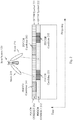
Fig. 2 is a schematic diagram of an exemplary control channel configuration in a wireless communication system, consistent with embodiments of the present application. A 5G new radio system, for example, uses OFDM waveform for the wireless communications. As in existing LTE cellular networks, communications are measured in time frames, each frame is divided into slots, and each slot may contain multiple OFDM symbols each spanning over the multiple frequency subcarriers. Resources are defined in time (OFDM symbols) and frequency (subcarriers). - A PDCCH search space is a set of resources that a user device, e.g., 140, may assume carrying its PDCCH candidates and attempt to search and decode to obtain control information. Without loss of generality, for a user device, the instances of resources where PDCCHs are configured to be transmitted (or the instances that the user device is configured to monitor its PDCCH) are called scheduling (or PDCCH) instances hereinafter. User device 140 may conduct blind decoding of all the PDCCH instances in its search space until it successfully decodes its PDCCH candidate. Once PDCCH is successfully decoded, user device 140 proceeds to receive and decode data transmitted from the base station on a data channel such as physical downlink shared channel (PDSCH). If, user device 140 fails to decode a PDCCH in its search space, user device 140 may assume no PDCCH is transmitted at that scheduling instance and may not decode its PDSCH.
- PDCCHs can be transmitted in a flexible manner, with the CORESETs configured at a symbol level, a slot level, or a multi-slot level. Consistent with embodiments of the present disclosure, a control resource set (CORESET) may be defined as the user device 140's PDCCH search space may be located and may be user-device specific, and may differ from user device to user device. For example, as shown in
Fig. 2 ,base station 120 may use twobeams 210 and 320 in the system to transmit PDCCH. Each beam may carry a different OFDM symbol. For example,beam 210 carriesOFDM symbol 231, andbeam 220 carriesOFDM symbol 232. Accordingly,base station 120 may configure PDCCH CORESET 261 onOFDM symbol 231 for the userdevice receiving beam 210 and PDCCH CORESET 262 onOFDM symbol 232 for the userdevice receiving beam 220. PDCCH CORESET 261 may includePDCCH candidates 241 and 242. PDCCH CORESET 262 may includePDCCH candidates devices receiving beams -
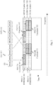
Fig. 3 is a schematic diagram of an exemplary control channel configuration in a wireless communication system, consistent with embodiments of the present application. As shown in the figure,base station 120 may configure two CORESETs,PDCCH CORESET 361 on oneOFDM symbol 331 and PDCCH CORESET 362 on twoOFDM symbols PDCCH CORESET 361 includes a PDCCH candidate 341. PDCCH CORESET 362 includes two PDCCH CORESETs 351 and 352. - A CORESET may include multiple CCEs (and therefore multiple REGs). For example, in
Fig. 3 , PDCCH CORESET 362 may include PDCCH candidates 351 and 352. PDCCH candidate 351 may be used to carryCCE 312, and PDCCH candidate 352 may be used to carry another CCE. Thus, PDCCH CORESET 362 may include at least 2 CCEs, where PDCCH candidate 351 may include 4 REGs and PDCCH candidate 352 may include another 4 REGs. Therefore, PDCCH CORESET 362 may include at least 8 REGs. PDCCH search space may be located on PDCCH candidate 351, PDCCH candidate 352, or both. - With PDCCH CORESET 362 occupying two OFDM symbols,
base station 120 may configure CORESETs with a time-first CCE-to-REG mapping, such that each CCE is mapped to REGs starting in the time domain (i.e., across the multiple OFDM symbols) and then in the frequency domain (i.e., across subcarriers) if available. As shown inFig. 3 , PDCCH candidate 351 is mapped in time domain first, and then in the frequency domain.REG# 1, #2, #3, and #4 ofCCE 312 are mapped to the four REGs of PDCCH candidate 351 acrossOFDM symbols - Alternatively,
base station 120 may configure CORESET with a frequency-first CCE-to-REG mapping, such that each CCE is mapped to REGs starting in the frequency domain (i.e., across subcarriers) and then in the time domain (i.e., across OFDM symbols) if available. As shown inFig. 3 , PDCCH candidate 352 is mapped in time domain first, and then in the frequency domain. -
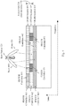
Figs. 2 and3 show that a user device is configured with one CORESET by the base station. Alternatively, a user device may be configured with multiple PDCCH CORESETs. As an example, inFig. 4 , which shows a schematic diagram of another exemplary control channel configuration,base station 120 configures one PDCCH CORESET 462 for user device 160 onOFDM symbol 432, but may configure two PDCCH CORESETs, 461 and 463, for user device 140 onOFDM symbols 431 and 433. - The base station may also configure CORESETs dynamically or semi-statically. For example, when the capacity of a user device is low, the base station may configure only one CORESET; otherwise the base station may configure multiple CORESETs for the user device. Even though multiple CORESETs on multiple OFDM symbols may be configured, not all CORESETs necessarily have to be used to transmit PDCCH. For example, the base station may configure 3 CORESETs, as in
Fig. 4 , for PDCCH transmission for all user devices in a cell. In some PDCCH scheduling instances,PDCCH CORESET 463 may not be used due to either capacity or other scheduling consideration, and onlyPDCCH CORESET 461 and 462 (i.e.,OFDM symbols 431 and 432) are used. Not knowing exactly which CORESETs are used, a user device may need to monitor the PDCCH control region and try to blind decode PDCCH candidates in all configured CORESETs. Alternatively, the base station may inform the user devices the instant PDCCH time duration, i.e., the duration of PDCCH transmission, such that the user device knows which PDCCH candidates to decode and blind decoding is unnecessary. - The instant PDCCH time duration is the total number of OFDM symbols used for PDCCH transmission. In other words, it is a combination of time duration of all CORESETs (not the configured ones) that are actually used by the base station for a PDCCH scheduling instance. For example, if all three OFDM symbols, i.e.
PDCCH CORESETs Fig. 4 , are used for PDCCH transmissions at a particular PDCCH scheduling instance, the instant number of OFDM symbols (or PDCCH time duration) is 3; if only the first two OFDM symbols, i.e.PDCCH CORESETs 461 and 462 shown inFig. 4 , are used for PDCCH transmissions, the instant total number of OFDM symbols (or PDCCH time duration) is 2. - In some examples,
base station 120 may signal this instant PDCCH time duration to all the user devices that are supposed to decode their PDCCHs at a scheduling instance. In some examples,base station 120 may dynamically send the PDCCH time duration prior to each scheduling instance on a common control channel. Alternatively,base station 120 may send the instant PDCCH time duration to all the user devices periodically over a certain time duration on a common control channel. In some examples, the base station may semi-statically send to the user devices by higher layer signaling. In the latter two cases, those user devices may assume the number of OFDM symbols that carry PDCCH does not change over the time duration before they receive the next signal. - In some examples, if a user device does not receive the PDCCH time duration from the base station, or if the received information may be inaccurate or outdated, it may choose to search for its PDCCH candidates over all the CORESETs that are configured for the user device.
- In some examples,
base station 120 may signal an instant PDCCH time duration to a group of user devices. For example,base station 120 may transmit a group's instant PDCCH time duration as described above. Those user devices in the group may receive the group's instant PDCCH time duration as described above. In some examples, if a user device in the group does not receive the PDCCH time duration from the base station, or if the received information may be inaccurate or outdated, it may choose to search for its PDCCH candidates over all the CORESETs that are configured for the user device. - In some examples,
base station 120 may signal an instant PDCCH time duration to a user device. For example,base station 120 may transmit an instant PDCCH time duration dedicated to a user device. The user device may receive its instant PDCCH time duration. In some examples, if the user device does not receive its PDCCH time duration from the base station, or if the received information may be inaccurate or outdated, it may choose to search for its PDCCH candidates over all the CORESETs that are configured for the user device. -
Base station 120 may also signal the PDCCH configuration, including frequency allocation and time duration of the CORESETs and PDCCH candidates, to user devices via higher layer signals in a semi-static manner. Each CORESET may contain the CCEs that are the user device's PDCCH candidates and may be a search space for a user device. The search space of the user device (CCEs that may carry its PDCCH candidates) may be determined by implicit/explicit manner. The user device may blind decode its PDCCH candidates in its search space in each CORESET. Alternatively, the number of PDCCH candidates as well as their CCE aggregation levels in each search space may be configured and signaled to the user device explicitly. A CCE aggregation level is a number of CCEs that a PDCCH is transmitted on. A base station may transmit different PDCCHs in different CCE aggregation levels, such as 1, 2, 4, and 8 CCEs. For example,base station 120 may transmit one PDCCH byCCE 311 inFig. 3 if the aggregation level is 1. If the aggregation level is 2,base station 120 may transmit one PDCCH by bothCCEs - Accordingly, a user device may only need to detect PDCCH on those PDCCH CORESETs within the time duration of the control region. The user device may not detect the other configured PDCCH CORESETs that are not within the instant PDCCH time duration. In other words, the user device may only need to search on a reduced number of CCEs. As a result, the complex blind detection of PDCCH is avoided or reduced.
-
Fig. 5 is a schematic diagram of anexemplary method 500 for detecting a control channel in a wireless communication system, consistent with embodiments of the present application.Method 500 includes obtaining a time duration of a control region (step 510), determining whether a first control resource set is within the time duration (step 520), and responsive to a determination that the first control resource set is within the time duration, detecting a control channel in the first control resource set (step 530). In some embodiments,method 500 may also include determining whether a second control resource set is within the time duration (step 560), and responsive to a determination that the second control resource set is within the time duration, detecting the control channel in the second control resource set (step 570). - Step 510 includes obtaining a time duration of a control region. For example, user device 140 may receive the time duration, i.e., the number of OFDM symbols for PDCCH transmission, from
base station 120. User device 140 may obtain the time duration of the control region intended for user device 140 instep 510. For example, user device 140 may receive instantPDCCH time duration 470 inFig. 4 from its previous PDCCHs periodically. Alternatively, user device 140 may obtain the time duration of the control region from a broadcast system information. For example, user device 140 may receive instantPDCCH time duration 470 from a broadcast channel transmitted bybase station 120. - Step 520 includes determining whether a control resource set is within the time duration. For example, user device 140 may obtain instant
PDCCH time duration 470 inFig. 4 as 2 symbols. When user device 140 is configured with PDCCH CORESET 462 inFig. 4 , user device 140 may determine its PDCCH CORESET 462 is withininstant PDCCH duration 470. - Step 530 includes responsive to a determination that the control resource set is within the time duration, detecting a control channel in the first control resource set. For example, user device 140 may determine its configured PDCCH CORESET 462 is within
instant PDCCH duration 470 instep 520. In response to the determination that its PDCCH CORESET 462 is within instantPDCCH time duration 470, user device 140 may detect its PDCCH onPDCCH candidates - Step 560 includes determining whether another control resource set is within the time duration. For example, user device 140 may obtain an instant PDCCH time duration as 3 symbols when user device 140 is configured with
PDCCH CORESETs PDCCH CORESET 461 is within the instant PDCCH time duration, user device 140 may determine thatPDCCH CORESET 463 is also within the instant PDCCH time duration instep 560. - Step 570 includes responsive to a determination that the another control resource set is within the time duration, detecting the control channel in the another control resource set. For example, user device 140 may determine its
PDCCH CORESET 463 is within the instant PDCCH time duration after determiningPDCCH CORESET 461 is within the instant PDCCH time duration. In response to the determination that its second configuredPDCCH CORESET 463 is within the instant PDCCH time duration, user device 140 may detect its PDCCH onPDCCH candidates 442 on OFDM symbol 433 instep 570. - In some embodiments,
method 500 may include responsive to a determination that the control resource set is not within the time duration, not detecting the control channel in the first control resource set. For example, user device 160 may obtain an instant PDCCH time duration as 1 symbol when user device 160 is configured with PDCCH CORESET 462. In response to a determination that PDCCH CORESET 462 is not within the instant PDCCH time duration, user device 160 may not detect its PDCCH onPDCCH candidates - In some embodiments,
method 500 may include responsive to a determination that the control resource set is partially within the time duration, detecting the control channel in the first control resource set. For example, user device 160 may obtain an instant PDCCH time duration as 1 symbol when user device 160 is configured with a PDCCH CORESET on bothOFDM symbol - In some embodiments,
method 500 may include responsive to a determination that the control resource set is partially within the time duration, not detecting the control channel in the first control resource set. For example, user device 160 may obtain an instant PDCCH time duration as 1 symbol when user device 160 is configured with a PDCCH CORESET on bothOFDM symbol - In some embodiments, obtaining the time duration of the control region in
step 510 may include receiving the time duration of the control region in the first symbol of a time slot or a scheduling instant. For example, whenOFDM symbol 431 inFig. 4 is the first symbol of a time slot or a scheduling instant, user device 140 may receiveinstant PDCCH duration 470 inOFDM symbol 431 . - In some embodiments, obtaining the time duration of the control region in
step 510 may include receiving the time duration of the control region periodically. For example, user device 140 may periodically receive an update of instantPDCCH time duration 470 frombase station 120 every 100 milliseconds (ms). - In some embodiments, obtaining the time duration of the control region in
step 510 may include receiving the time duration of the control region semi-statically. For example, user device 140 may receive instantPDCCH time duration 470 semi-statically transmitted bybase station 120.Base station 120 may transmit, for example, a radio resource control (RRC) configuration signal including the instant PDCCH time duration when an update of the instant PDCCH time duration is needed. Accordingly, user device 140 may receive an updated instant PDCCH time duration through the RRC configuration signal. Before receiving another updated one, user device 140 may continue to use the current one as its instant PDCCH time duration. - In some embodiments, obtaining the time duration of the control region in
step 510 may include obtaining the time duration of the control region based on a default time duration. For example, user device 140 may presume a default instant PDCCH time duration to be 3 OFDM symbols. Before each scheduling instant, user device 140 may use the default instant PDCCH time duration to compare with its configured PDCCH CORESETs. In some examples, user device 140 may obtain a default instant PDCCH time duration according to its system bandwidth or frequencies. For example, if user device 140 supports only 20 MHz or below, user device 140 may use 3 OFDM symbols as its default instant PDCCH time duration. - In some embodiments, obtaining the time duration of the control region in
step 510 may include obtaining the time duration of the control region by using a previous time duration. For example, user device 140 may receive an instant PDCCH time duration in the first OFDM symbol of each time slot. When user device 140 does not receive any instant PDCCH time duration in the first OFDM symbol of a certain time slot, use device 140 may reuse the previous instant PDCCH time duration. - In some embodiments, obtaining the time duration of the control region in
step 510 may include obtaining the time duration of the control region based on a whole control region of a cell. For example, whenbase station 120 signals multiple PDCCH CORESETs for user devices, user device 140 may presume that the instant PDCCH time duration includes OFDM symbols covering all the PDCCH CORESETs signaled bybase station 120. - In some embodiments, the control resource set may be configured on one or more symbols. For example, as shown in
Fig. 3 ,base station 120 may configure PDCCH CORESET 362 on twoOFDM symbols - In some embodiments, a first control resource set is configured on one or more symbols, and a second control resource set is configured on one or more symbols which could be different from those configured for the first control resource set. For example, as shown in
Fig. 3 ,base station 120 may respectively configurePDCCH CORESET 361 onOFDM symbol 331, and PDCCH CORESET 362 onsymbol OFDM symbol 331 is not overlapped withOFDM symbols - In some embodiments, a first control resource set and a second control resource set may be configured on at least a common symbol. For example,
base station 120 may configure a PDCCH CORESET on OFDM twosymbols # 1 and #2, and another PDCCH CORESET on twoOFDM symbols # 2 and #3. Thus, the two PDCCH CORESETs are configured on a commonOFDM symbol # 2. - In some embodiments, the first control resource set may be transmitted in a first beam, and the second control resource set may be transmitted in a second beam. For example,
base station 120 inFig. 4 may respectively transmit a PDCCH onPDCCH CORESET 461 inbeam 410, and another PDCCH on PDCCH CORESET 462 inbeam 220. - In some embodiments, the first control resource set may include a plurality of resource elements (REs), and the control channel is transmitted on at least a part of REs according to a frequency-first mapping, a time-first mapping, or a combination thereof. In
Fig. 3 , for example,base station 120 may configure PDCCH CORESET 362 including PDCCH candidates 351 and 352. PDCCH candidates 351 and 352 each include four REGs, and therefore include a plurality of REs. In other words, PDCCH CORESET 362 may include a plurality of REs. - When
base station 120 transmits a PDCCH on, for example, PDCCH candidate 351, the fourREGs # 1, #2, #3, and #4 of PDCCH candidate 351 are used to carry the PDCCH according to a time-first mapping. As shown inFig. 3 ,REG # 1 and #2 of PDCCH candidate 351 are mapped acrossOFDM symbols REG # 3 and #4 of PDCCH 351 are mapped, i.e., the time-first mapping. - Alternatively,
base station 120 may transmit a PDCCH on, for example, PDCCH candidate 352, the fourREGs # 1, #2, #3, and #4 of PDCCH candidate 352 are used to carry the PDCCH according to a frequency-first mapping. As shown inFig. 3 ,REG # 1 and #2 of PDCCH candidate 352 are first mapped to across subcarriers in the frequency domain onOFDM symbol 332, and then, across toOFDM symbol 333,REG # 3 and #4 of PDCCH 352 are mapped, i.e., the frequency-first mapping. - In another example,
base station 120 may transmit a PDCCH on both PDCCH candidates 351 and 352. According to the time-first and the frequency-first mappings described in the above two examples on PDCCH candidates 351 and 352, the PDCCH transmitted on both PDCCH candidates 351 and 352 are transmitted according to a combination of the time-first and the frequency-first mappings. - In some embodiments, detecting a control channel in
step 530 may include detecting on which part of REs the control channel is transmitted. For example, when user device 160 is configured with PDCCH CORESET 462,base station 120 may transmit a PDCCH on eitherPDCCH candidate PDCCH candidate 451 or REGs ofPDCCH candidate 452. -
Fig. 6 is a schematic diagram of anexemplary method 600 for transmitting a control channel in a wireless communication system, according to some embodiments of the present application.Method 600 includes transmitting a time duration of a control region (step 610), determining whether a first control resource set is within the time duration (step 620), and responsive to a determination that the first control resource set is within the time duration, transmitting a control channel in the first control resource set (step 630). In some examples,method 600 may also include determining whether a second control resource set is within the time duration (step 660), and responsive to a determination that the second control resource set is within the time duration, transmitting the control channel in the second control resource set (step 670). - Step 610 includes transmitting a time duration of a control region.
Base station 120 may transmit the time duration of the control region for all user devices, a group of user devices, or a user device incoverage 180. For example,base station 120 may transmit instantPDCCH time duration 470 inFig. 4 in user device 140's PDCCHs periodically. - Alternatively,
base station 120 may broadcast system information including the time duration of the control region for all user device incoverage 180. For example,base station 120 may transmit instantPDCCH time duration 470 in a broadcast channel (BCH). - Step 620 includes determining whether a first control resource set is within the time duration. For example,
base station 120 may transmit instantPDCCH time duration 470 as 2 symbols for all user devices, a group of user devices, or a user device.Base station 120 in any of these configurations may know that user device 140 has an instant PDCCH time duration of 2 symbols. - Moreover,
base station 120 may configure one or more PDCCH CORESETs for a user device. For example,base station 120 may configure user device 140 with PDCCH CORESET 462 inFig. 4 . Accordingly,base station 120 may determine that PDCCH CORESET 462 of user device 140 is within instantPDCCH time duration 470 whenbase station 120 intends to transmit a PDCCH to user device 140. - Step 630 includes responsive to a determination that the first control resource set is within the time duration, transmitting a control channel in the first control resource set. For example,
base station 120 may determine PDCCH CORESET 462 of user device 140 is within instantPDCCH time duration 470 obtained by user device 140. In response to the determination that PDCCH CORESET 462 of user device 140 is within instant PDCCH duration,base station 120 may transmit a PDCCH onPDCCH candidate 451 and/or 452 to user device 140. - Step 660 includes determining whether a second control resource set is within the time duration. For example,
base station 120 may transmit an instant PDCCH time duration of 3 symbols to user device 140.Base station 120 may also configure user device 140 withPDCCH CORESETs Fig. 4 . After determiningPDCCH CORESET 461 is within the instant PDCCH time duration,base station 120 may determine thatPDCCH CORESET 463 is also within the instant PDCCH time duration. - Step 670 includes responsive to a determination that the second control resource set is within the time duration, transmitting the control channel in the second control resource set. For example,
base station 120 may determinePDCCH CORESET 463 of user device 140 is within the instant PDCCH time duration of 3 symbols. In response to the determination that the second configuredPDCCH CORESET 463 is within the instant PDCCH time duration,base station 120 may transmit a PDCCH onPDCCH candidates 442 on OFDM symbol 433 to user device 140. - In some examples,
method 600 may include responsive to a determination that the first control resource set is not within the time duration, not transmitting the control channel in the first control resource set. For example,base station 120 may transmit to user device 160 an instant PDCCH time duration of 1 symbol.Base station 120 may also configure user device 160 with PDCCH CORESET 462. In response to a determination that PDCCH CORESET 462 is not within the instant PDCCH time duration,base station 120 may not transmit any PDCCH onPDCCH candidates - In some examples,
method 600 may include responsive to a determination that the first control resource set is partially within the time duration, transmitting the control channel in the first control resource set. For example,base station 120 may transmit user device 160 an instant PDCCH time duration as 1 symbol.Base station 120 may also configure user device 160 with a PDCCH CORESET on bothOFDM symbol base station 120 may transmit a PDCCH in the PDCCH CORESET of user device 160. - In some examples,
method 600 may include responsive to a determination that the first control resource set is partially within the time duration, not transmitting the control channel in the first control resource set. For example,base station 120 may transmit to user device 160 an instant PDCCH time duration as 1 symbol.Base station 120 may also configure user device 160 with a PDCCH CORESET on bothOFDM symbol base station 120 may not transmit any PDCCHs in the configured PDCCH CORESET to user device 160. - In some examples, transmitting the time duration of the control region in
step 610 may include transmitting the time duration of the control region in the first symbol of a time slot or a scheduling instant. For example,base station 120 may transmit instantPDCCH time duration 470 inOFDM symbol 431 to user device 140. - In some examples, transmitting the time duration of the control region in
step 610 may include transmitting the time duration of the control region periodically. For example,base station 120 may periodically transmit to use device 140 an updated instantPDCCH time duration 470 every 100 ms. - In some examples, transmitting the time duration of the control region in
step 610 may include receiving the time duration of the control region semi-statically. For example,base station 120 may semi-statically transmit to use device 140 instantPDCCH time duration 470.Base station 120 may transmit, for example, a radio resource control (RRC) configuration signal including instantPDCCH time duration 470 when an update of the instant PDCCH time duration is needed. - In some examples, transmitting the time duration of the control region in
step 610 may include transmitting the time duration of the control region based on a whole control region of a cell. For example,base station 120 may broadcast its instant PDCCH time duration in a BCH. All user devices may receivebase station 120's instant PDCCH time duration as a whole control region ofbase station 120. Any user device incoverage 180 may receive the BCH to obtain a size of a whole control region ofbase station 120. - In some examples,
base station 120 may signal multiple PDCCH CORESETs for a user device.Base station 120 may use an instant PDCCH time duration covering all of these PDCCH CORESETs of a user device as a whole control region. - In some examples,
base station 120 may configure the first control resource set on one or more symbols. InFig. 3 , for example,base station 120 may configure PDCCH CORESET 362 onOFDM symbol - In some examples, a first control resource set is configured on one or more symbols, and a second control resource set is configured on one or more symbols which could be different from those configured for the first control resource set. For example, as shown in
Fig. 3 ,base station 120 may respectively configurePDCCH CORESET 361 onOFDM symbol 331, and PDCCH CORESET 362 onsymbol OFDM symbol 331 is not overlapped withOFDM symbols - In some examples, a first control resource set and a second control resource set may be configured on at least a common symbol. For example,
base station 120 may configure a PDCCH CORESET on OFDM twosymbols # 1 and #2, and another PDCCH CORESET on twoOFDM symbols # 2 and #3. Thus, the two PDCCH CORESETs are configured on a commonOFDM symbol # 2. - In some examples, the first control resource set may be transmitted in a first beam, and the second control resource set may be transmitted in a second beam. For example,
base station 120 inFig. 4 may respectively transmit a PDCCH onPDCCH CORESET 461 inbeam 410, and another PDCCH on PDCCH CORESET 462 inbeam 420. - In some examples, the first control resource set may include a plurality of resource elements (REs), and the control channel is transmitted on at least a part of REs according to a frequency-first mapping, a time-first mapping, or a combination thereof. In
Fig. 3 , for example,base station 120 may configure PDCCH CORESET 362 including PDCCH candidates 351 and 352. PDCCH candidates 351 and 352 each include four REGs, and therefore include a plurality of REs, respectively. In other words, PDCCH CORESET 362 may include a plurality of REs. - When
base station 120 transmits a PDCCH on, for example, PDCCH candidate 351, the fourREGs # 1, #2, #3, and #4 of PDCCH candidate 351 are used to carry the PDCCH according to a time-first mapping. As shown inFig. 3 ,base station 120 may mapREG # 1 and #2 of PDCCH candidate 351 acrossOFDM symbols REG # 3 and #4 of PDCCH 351, i.e., the time-first mapping. - Alternatively,
base station 120 may transmit a PDCCH on, for example, PDCCH candidate 352, the fourREGs # 1, #2, #3, and #4 of PDCCH candidate 352 are used to carry the PDCCH according to a frequency-first mapping. As shown inFig. 3 ,base station 120 may mapREG # 1 and #2 of PDCCH candidate 352 first across subcarriers in the frequency domain onOFDM symbol 332, and then, across toOFDM symbol 333,REG # 3 and #4 of PDCCH 352, i.e., the frequency-first mapping. - In another example,
base station 120 may transmit a PDCCH on both PDCCH candidates 351 and 352. According to the time-first and the frequency-first mappings described in the above two examples on PDCCH candidates 351 and 352,base station 120 may transmit the PDCCH on both PDCCH candidates 351 and 352 according to a combination of the time-first and the frequency-first mappings. - In some examples, transmitting a control channel in
step 630 may include transmitting the control channel on a part of REs. For example, when user device 160 is configured with PDCCH CORESET 462,base station 120 may transmit a PDCCH to user device 160 on eitherPDCCH candidate Base station 120 may transmit the PDCCH on REGs ofPDCCH candidate 451 or REGs ofPDCCH candidate 452. -
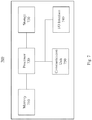
Fig. 7 is a schematic diagram of anexemplary user device 700 for detecting a control channel in a wireless communication system, according to some embodiments of the present application.User device 700 may include amemory 710, aprocessor 720, astorage 730, an I/O interface 740, and acommunication unit 750. One or more of the components ofuser device 700 may be included for detecting control channels in a wireless communication system. These units may be configured to transfer data and send or receive instructions between or among each other. -
Processor 720 may include any appropriate type of general-purpose or special-purpose microprocessor, digital signal processor, or microcontroller. For example,processor 720 may be configured to receive the time duration, i.e., the number of OFDM symbols for PDCCH transmission, frombase station 120. In some embodiments,processor 720 may be configured to obtain the time duration of the control region intended foruser device 700. For example,processor 720 may be configured to receive instantPDCCH time duration 470 inFig. 4 fromuser device 700's previous PDCCHs periodically. Alternatively,processor 720 may be configured to obtain the time duration of the control region from a broadcast system information. For example,processor 720 may be configured to receive instantPDCCH time duration 470 from a broadcast channel transmitted bybase station 120. -
Processor 720 may also be configured to determine whether a control resource set is within the time duration. For example,processor 720 may be configured to obtain instantPDCCH time duration 470 inFig. 4 as 2 symbols. Whenuser device 700 is configured with PDCCH CORESET 462 inFig. 4 ,processor 720 may be configured to determineuser device 700's PDCCH CORESET 462 is withininstant PDCCH duration 470. -
Processor 720 may further configured to, in response to a determination that the control resource set is within the time duration, detect a control channel in the first control resource set. For example,processor 720 may be configured to determineuser device 700's configured PDCCH CORESET 462 is withininstant PDCCH duration 470. In response to the determination that its PDCCH CORESET 462 is within instantPDCCH time duration 470,processor 720 may be configured to detect its PDCCH onPDCCH candidates - In some examples,
processor 720 may be configured to determine whether another control resource set is within the time duration. For example,user device 700 may obtain an instant PDCCH time duration as 3 symbols whenuser device 700 is configured withPDCCH CORESETs PDCCH CORESET 461 is within the instant PDCCH time duration,processor 720 may be configured to determine thatPDCCH CORESET 463 is also within the instant PDCCH time duration. -
Processor 720 may be configured to, in response to a determination that the another control resource set is within the time duration, detect the control channel in the another control resource set. For example,processor 720 may be configured to determine itsPDCCH CORESET 463 is within the instant PDCCH time duration after determiningPDCCH CORESET 461 is within the instant PDCCH time duration. In response to the determination that its second configuredPDCCH CORESET 463 is within the instant PDCCH time duration,processor 720 may be configured to detectuser device 700's PDCCH onPDCCH candidates 442 on OFDM symbol 433. - In some embodiments,
processor 720 may also be configured to perform one of those steps described above formethod 500. -
Memory 710 andstorage 730 may include any appropriate type of mass storage provided to store any type of information thatprocessor 720 may need to operate.Memory 710 andstorage 730 may be a volatile or non-volatile, magnetic, semiconductor, tape, optical, removable, non-removable, or other type of storage device or tangible (i.e., non-transitory) computer-readable medium including, but not limited to, a read-only memory (ROM), a flash memory, a dynamic random-access memory (RAM), and a static RAM.Memory 710 and/orstorage 730 may be configured to store one or more computer programs that may be executed byprocessor 720 to perform exemplary detecting control channels in a wireless communication system disclosed in this application. -
Memory 710 and/orstorage 730 may be further configured to store information and data used byprocessor 720. For instance,memory 710 and/orstorage 730 may be configured to store a received instant PDCCH time duration, a previous instant PDCCH time duration, a default instant PDCCH time duration, and PDCCH CORESETs. - I/
O interface 740 may be configured to facilitate the communication betweenuser device 700 and other apparatuses. For example, I/O interface 740 may receive a signal from another apparatus (e.g., a computer) that system configuration foruser device 700. I/O interface 740 may also output data of detecting statistics to other apparatuses. -
Communication unit 750 may include one or more cellular communication modules, including, for example, a 5G new radio system, a Long-Term Evolution (LTE), a High Speed Packet Access (HSPA), a Wideband Code-Division Multiple Access (WCDMA), and/or a Global System for Mobile communication (GSM) communication module. -
Fig. 8 is a schematic diagram of anexemplary network apparatus 800 for transmitting a control channel in a wireless communication system, according to some embodiments of the present application.Network apparatus 800 may include amemory 810, aprocessor 820, astorage 830, an I/O interface 840, and acommunication unit 850. One or more of the components ofnetwork apparatus 800 may be included for transmitting control channels in a wireless communication system. These units may be configured to transfer data and send or receive instructions between or among each other. -
Processor 820 may include any appropriate type of general-purpose or special-purpose microprocessor, digital signal processor, or microcontroller.Processor 820 may be configured to transmit a time duration of a control region.Processor 820 may be configured to transmit the time duration of the control region for all user devices, a group of user devices, or a user device incoverage 180. For example,processor 820 may be configured to transmit instantPDCCH time duration 470 inFig. 4 in user device 140's PDCCHs periodically. - Alternatively,
processor 820 may be configured to broadcast system information including the time duration of the control region for all user device incoverage 180. For example,processor 820 may be configured to transmit instantPDCCH time duration 470 in a broadcast channel (BCH) ofnetwork apparatus 800. -
Processor 820 may also be configured to determine whether a first control resource set is within the time duration. For example,processor 820 may be configured to transmit instantPDCCH time duration 470 as 2 symbols for all user devices, a group of user devices, or a user device.Base station 120 in any of these configurations may know that user device 140 has an instant PDCCH time duration of 2 symbols. - Moreover,
processor 820 may be configured to configure one or more PDCCH CORESETs for a user device. For example,processor 820 may be configured to configure user device 140 with PDCCH CORESET 462 inFig. 4 . Accordingly,processor 820 may be configured to determine that PDCCH CORESET 462 of user device 140 is within instantPDCCH time duration 470 whenbase station 120 intends to transmit a PDCCH to user device 140. -
Processor 820 may further be configured to, in response to a determination that the first control resource set is within the time duration, transmit a control channel in the first control resource set. For example,processor 820 may be configured to determine PDCCH CORESET 462 of user device 140 is within instantPDCCH time duration 470. In response to the determination that PDCCH CORESET 462 of user device 140 is within instant PDCCH duration,processor 820 may be configured to transmit a PDCCH onPDCCH candidate 451 and/or 452 to user device 140. -
Processor 820 may be configured to determine whether a second control resource set is within the time duration. For example,processor 820 may be configured to transmit an instant PDCCH time duration of 3 symbols to user device 140.Processor 820 may also be configured to configure user device 140 withPDCCH CORESETs Fig. 4 . After determiningPDCCH CORESET 461 is within the instant PDCCH time duration,processor 820 may be configured to determine thatPDCCH CORESET 463 is also within the instant PDCCH time duration. -
Processor 820 may be configured to, in response to a determination that the second control resource set is within the time duration, transmit the control channel in the second control resource set. For example,processor 820 may be configured to determinePDCCH CORESET 463 of user device 140 is within the instant PDCCH time duration of 3 symbols. In response to the determination that the second configuredPDCCH CORESET 463 is within the instant PDCCH time duration,processor 820 may be configured to transmit a PDCCH onPDCCH candidates 442 on OFDM symbol 433 to user device 140. - In some embodiments,
processor 820 may also be configured to perform one of those steps described above formethod 600. -
Memory 810 andstorage 830 may include any appropriate type of mass storage provided to store any type of information thatprocessor 820 may need to operate.Memory 810 andstorage 830 may be a volatile or non-volatile, magnetic, semiconductor, tape, optical, removable, non-removable, or other type of storage device or tangible (i.e., non-transitory) computer-readable medium including, but not limited to, a read-only memory (ROM), a flash memory, a dynamic random-access memory (RAM), and a static RAM.Memory 810 and/orstorage 830 may be configured to store one or more computer programs that may be executed byprocessor 820 to perform exemplary transmitting control channels in a wireless communication system disclosed in this application. -
Memory 810 and/orstorage 830 may be further configured to store information and data used byprocessor 820. For instance,memory 810 and/orstorage 830 may be configured to store system information, an instant PDCCH time duration for each user device, a previous instant PDCCH time duration, a default instant PDCCH time duration, and CORESETs for each user device. - I/
O interface 840 may be configured to facilitate the communication betweennetwork apparatus 800 and other apparatuses. For example, I/O interface 840 may receive a signal from another apparatus (e.g., a computer) that system configuration fornetwork apparatus 800. I/O interface 840 may also output data of transmitting statistics to other apparatuses. -
Communication unit 850 may include one or more cellular communication modules, including, for example, a 5G new radio system, a Long-Term Evolution (LTE), a High Speed Packet Access (HSPA), a Wideband Code-Division Multiple Access (WCDMA), and/or a Global System for Mobile communication (GSM) communication module. - In some aspects, the present application is directed to a non-transitory computer-readable medium storing instructions, which, when executed, cause one or more processors to perform the methods, as discussed above. The computer-readable medium may include volatile or non-volatile, magnetic, semiconductor, tape, optical, removable, non-removable, or other types of computer-readable medium or computer-readable storage devices. For example, the computer-readable medium may be the storage device or the memory module having the computer instructions stored thereon, as disclosed. In some embodiments, the computer-readable medium may be a disc or a flash drive having the computer instructions stored thereon.
- It will be appreciated that the present disclosure is not limited to the exact construction that has been described above and illustrated in the accompanying drawings, and that various modifications and changes can be made without departing from the scope thereof. It is intended that the scope of the application should only be limited by the appended claims.
Claims (14)
- A method of control channel detection (500) for a wireless communication device, comprising the following steps:obtaining (510) a time duration of a control region;determining (520) whether a first control resource set is within the time duration;responsive to a determination that the first control resource set is within the time duration, detecting (530) a control channel in the first control resource set, characterized by the subsequent steps of:determining (560) whether a second control resource set is within the time duration; andresponsive to a determination that the second control resource set is within the time duration, detecting (570) the control channel in the second control resource set.
- The method of claim 1, wherein the first control resource set is configured for a user device to detect the user device's control channel.
- The method of claim 1, further comprising:
responsive to a determination that the first control resource set is not within the time duration, not detecting the control channel in the first control resource set. - The method of claim 1, further comprising:
responsive to a determination that the first control resource set is partially within the time duration, detecting the control channel in the first control resource set. - The method of claim 1, further comprising:
responsive to a determination that the first control resource set is partially within the time duration, not detecting the control channel in the first control resource set. - The method of claim 1, wherein obtaining the time duration of the control region includes:receiving the time duration of the control region in the first symbol of a time slot or a scheduling instant;receiving the time duration of the control region periodically;receiving the time duration of the control region semi-statically;obtaining the time duration of the control region based on a default time duration;obtaining the time duration of the control region by using a previous time duration;obtaining the time duration of the control region based on a whole control region of a cell; orany combination thereof.
- The method of claim 1, wherein the first control resource set is configured on one or more symbols.
- The method of claim 1, wherein the second control resource set is configured for the user device to detect the user device's control channel.
- The method of claim 1, wherein:the first control resource set is configured on one or more symbols, andthe second control resource set is configured on one or more symbols.
- The method of claim 9, wherein the first control resource set and the second control resource set are configured on at least a common symbol.
- The method of claim 1, wherein:the first control resource set is transmitted in a first beam, andthe second control resource set is transmitted in a second beam.
- The method of claim 1, wherein:the first control resource set includes a plurality of resource elements, REs, andthe control channel is transmitted on at least a part of REs according to a frequency-first mapping, a time-first mapping, or a combination thereof.
- The method of claim 11, wherein detecting the control channel in the first control resource set includes detecting on which part of REs the control channel is transmitted.
- A user device, comprising:a memory storing instructions; anda processor communicatively coupled to the memory,wherein the instructions, when executed by the processor, cause the processor to perform the method according to any of claims 1 to 13.
Priority Applications (2)
| Application Number | Priority Date | Filing Date | Title |
|---|---|---|---|
| EP20176369.5A EP3720035A1 (en) | 2017-05-02 | 2018-04-18 | Monitoring multiple control channels in wireless communication systems |
| PL18793890T PL3488651T3 (en) | 2017-05-02 | 2018-04-18 | Methods and apparatuses for detecting control channels in wireless communication systems |
Applications Claiming Priority (2)
| Application Number | Priority Date | Filing Date | Title |
|---|---|---|---|
| US201762500151P | 2017-05-02 | 2017-05-02 | |
| PCT/CN2018/083520 WO2018201892A1 (en) | 2017-05-02 | 2018-04-18 | Methods and apparatuses for detecting control channels in wireless communication systems |
Related Child Applications (2)
| Application Number | Title | Priority Date | Filing Date |
|---|---|---|---|
| EP20176369.5A Division EP3720035A1 (en) | 2017-05-02 | 2018-04-18 | Monitoring multiple control channels in wireless communication systems |
| EP20176369.5A Division-Into EP3720035A1 (en) | 2017-05-02 | 2018-04-18 | Monitoring multiple control channels in wireless communication systems |
Publications (3)
| Publication Number | Publication Date |
|---|---|
| EP3488651A1 EP3488651A1 (en) | 2019-05-29 |
| EP3488651A4 EP3488651A4 (en) | 2019-07-03 |
| EP3488651B1 true EP3488651B1 (en) | 2020-07-15 |
Family
ID=64016393
Family Applications (2)
| Application Number | Title | Priority Date | Filing Date |
|---|---|---|---|
| EP20176369.5A Withdrawn EP3720035A1 (en) | 2017-05-02 | 2018-04-18 | Monitoring multiple control channels in wireless communication systems |
| EP18793890.7A Active EP3488651B1 (en) | 2017-05-02 | 2018-04-18 | Methods and apparatuses for detecting control channels in wireless communication systems |
Family Applications Before (1)
| Application Number | Title | Priority Date | Filing Date |
|---|---|---|---|
| EP20176369.5A Withdrawn EP3720035A1 (en) | 2017-05-02 | 2018-04-18 | Monitoring multiple control channels in wireless communication systems |
Country Status (18)
| Country | Link |
|---|---|
| US (2) | US11245506B2 (en) |
| EP (2) | EP3720035A1 (en) |
| JP (1) | JP7145878B2 (en) |
| KR (1) | KR20200003027A (en) |
| CN (2) | CN109792744B (en) |
| AU (1) | AU2018262868B2 (en) |
| BR (1) | BR112019023031A2 (en) |
| CA (1) | CA3061774C (en) |
| CL (1) | CL2019003132A1 (en) |
| ES (1) | ES2811510T3 (en) |
| IL (1) | IL270340B2 (en) |
| MX (1) | MX2019013073A (en) |
| PH (1) | PH12019502467A1 (en) |
| PL (1) | PL3488651T3 (en) |
| RU (1) | RU2760208C2 (en) |
| SG (1) | SG11201910087XA (en) |
| WO (1) | WO2018201892A1 (en) |
| ZA (1) | ZA201907451B (en) |
Families Citing this family (7)
| Publication number | Priority date | Publication date | Assignee | Title |
|---|---|---|---|---|
| EP3873020B1 (en) * | 2017-05-03 | 2024-05-01 | InterDigital Patent Holdings, Inc. | Beam-based pdcch transmission in nr |
| US10897753B2 (en) * | 2017-05-04 | 2021-01-19 | Sharp Kabushiki Kaisha | Systems and methods for supporting multiple allocations in UL/DL grant for a 5G NR UE and gNB |
| KR102435618B1 (en) * | 2017-06-15 | 2022-08-24 | 삼성전자주식회사 | Apparatus and method for transmitting downlink control channel in wireless communication system |
| KR20190070146A (en) * | 2017-12-12 | 2019-06-20 | 삼성전자주식회사 | Apparatus and method for transmitting or receiving signal using beamforming in wireless communication system |
| US11032824B2 (en) | 2018-11-02 | 2021-06-08 | Qualcomm Incorporated | Downlink control channel monitoring capabilities |
| US11051292B2 (en) | 2018-11-12 | 2021-06-29 | Qualcomm Incorporated | Control channel limitations for enhanced low latency processing |
| CN110786035B (en) * | 2019-09-26 | 2024-04-26 | 小米通讯技术有限公司 | Processing method and device for control resource set and computer storage medium |
Family Cites Families (42)
| Publication number | Priority date | Publication date | Assignee | Title |
|---|---|---|---|---|
| CN101578775B (en) | 2007-01-04 | 2013-08-28 | 高通股份有限公司 | Method and apparatus for utilizing other sector interference (OSI) indication |
| KR101650749B1 (en) * | 2009-08-18 | 2016-08-24 | 삼성전자주식회사 | Method and apparatus for allocation and indication of control channel in backhaul subframe for relay |
| CN102170703A (en) | 2011-05-11 | 2011-08-31 | 电信科学技术研究院 | Method for receiving and transmitting information on physical downlink control channel and equipment thereof |
| CN108551388B (en) * | 2011-08-11 | 2021-08-17 | 瑞典爱立信有限公司 | Radio network node, user equipment and method for extended control channel use |
| TW201322681A (en) * | 2011-09-26 | 2013-06-01 | Innovative Sonic Corp | Method and apparatus for processing Channel State Information in a wireless communication system |
| CN102395206B (en) | 2011-11-08 | 2015-07-15 | 电信科学技术研究院 | Transmission method and equipment for downside control information |
| WO2014067146A1 (en) * | 2012-11-02 | 2014-05-08 | 华为技术有限公司 | Control channel detection method and device |
| KR101942062B1 (en) | 2012-11-21 | 2019-01-24 | (주)테크윙 | Pick and place apparatus for test handler |
| WO2017023146A1 (en) * | 2015-08-06 | 2017-02-09 | Innovative Technology Lab Co., Ltd. | Apparatus and method for transmitting uplink control information through a physical uplink control channel |
| EP3131223B1 (en) | 2015-08-11 | 2018-06-27 | Panasonic Intellectual Property Corporation of America | Improved blind decoding of (e)pdcch for partial subframes |
| JP6153575B2 (en) * | 2015-08-13 | 2017-06-28 | 株式会社Nttドコモ | User terminal, radio base station, and radio communication method |
| US10321447B2 (en) * | 2015-10-26 | 2019-06-11 | Qualcomm Incorporated | Determining a DRX configuration parameter based in part on an M-PDCCH parameter |
| IL262783B (en) * | 2016-05-11 | 2022-08-01 | Idac Holdings Inc | Systems and methods for beamformed uplink transmission |
| JP6935426B2 (en) * | 2016-05-11 | 2021-09-15 | コンヴィーダ ワイヤレス, エルエルシー | New wireless downlink control channel |
| US10630410B2 (en) * | 2016-05-13 | 2020-04-21 | Telefonaktiebolaget Lm Ericsson (Publ) | Network architecture, methods, and devices for a wireless communications network |
| US10367677B2 (en) * | 2016-05-13 | 2019-07-30 | Telefonaktiebolaget Lm Ericsson (Publ) | Network architecture, methods, and devices for a wireless communications network |
| US10462739B2 (en) * | 2016-06-21 | 2019-10-29 | Samsung Electronics Co., Ltd. | Transmissions of physical downlink control channels in a communication system |
| KR102618292B1 (en) * | 2016-08-11 | 2023-12-28 | 삼성전자 주식회사 | Method and apparatus for data transmission in new radio cellular network |
| US10631329B2 (en) * | 2016-08-12 | 2020-04-21 | Qualcomm Incorporated | Non-coherent joint transmission techniques |
| CA3044953C (en) * | 2016-11-25 | 2021-11-02 | Lg Electronics Inc. | Method and apparatus for designing broadcast channel for nr in wireless communication system |
| US10674485B2 (en) * | 2016-12-22 | 2020-06-02 | Qualcomm Incorporated | Common control resource set with user equipment-specific resources |
| US20190349915A1 (en) * | 2017-01-03 | 2019-11-14 | Lg Electronics Inc. | Method for transmitting/receiving signals by using beams in wireless communication system, and device for same |
| US11523376B2 (en) * | 2017-01-05 | 2022-12-06 | Huawei Technologies Co., Ltd. | Method for downlink control channel design |
| US10440703B2 (en) | 2017-01-10 | 2019-10-08 | Mediatek Inc. | Physical downlink control channel design for 5G new radio |
| EP3579480B1 (en) * | 2017-02-02 | 2022-08-17 | LG Electronics Inc. | Method for reporting channel state information in wireless communication system and apparatus for same |
| WO2018141246A1 (en) * | 2017-02-03 | 2018-08-09 | Huawei Technologies Co., Ltd. | Downlink control information for network coordination schemes |
| CN110235407B (en) * | 2017-02-03 | 2022-09-02 | Idac控股公司 | Transmission and reception of physical downlink control channel |
| US10959219B2 (en) * | 2017-02-06 | 2021-03-23 | Lg Electronics Inc. | Method for receiving downlink control channel in wireless communication system and device therefor |
| EP4262129A1 (en) * | 2017-02-06 | 2023-10-18 | Telefonaktiebolaget LM Ericsson (publ) | Data transmissions in control regions |
| US10432441B2 (en) * | 2017-02-06 | 2019-10-01 | Samsung Electronics Co., Ltd. | Transmission structures and formats for DL control channels |
| WO2018151871A2 (en) * | 2017-02-17 | 2018-08-23 | Intel IP Corporation | Control resource block set search space design |
| EP4117377A1 (en) * | 2017-03-07 | 2023-01-11 | Apple Inc. | Monitoring control channels in control resource sets for new radio |
| US10932278B2 (en) * | 2017-03-20 | 2021-02-23 | Convida Wireless, Llc | Scheduling and control in new radio using preemption indication |
| US10757581B2 (en) * | 2017-03-22 | 2020-08-25 | Mediatek Inc. | Physical downlink control channel design for NR systems |
| EP3602943A1 (en) * | 2017-03-24 | 2020-02-05 | Intel IP Corporation | Techniques to enable physical downlink control channel communications |
| US10925048B2 (en) * | 2017-03-30 | 2021-02-16 | Qualcomm Incorporated | Control resource set for single-carrier waveform |
| EP3603030B1 (en) * | 2017-04-03 | 2021-05-26 | Guangdong Oppo Mobile Telecommunications Corp., Ltd. | Methods and apparatuses for configuring a control resource set in a wireless communication system |
| CN110476377B (en) * | 2017-04-05 | 2022-09-13 | 苹果公司 | Apparatus for configuring control resource sets and machine-readable storage medium |
| US10511399B2 (en) * | 2017-04-07 | 2019-12-17 | Qualcomm Incorporated | Techniques and apparatuses for downlink control channel design using a top to bottom search space |
| CN108738149B (en) * | 2017-04-21 | 2022-05-17 | 宏达国际电子股份有限公司 | Apparatus and method for processing common search space |
| EP3937403B1 (en) * | 2017-04-24 | 2023-01-18 | LG Electronics Inc. | Method and apparatus for transmitting or receiving signal in wireless communication system |
| JP6752362B2 (en) * | 2017-04-28 | 2020-09-09 | 株式会社Nttドコモ | Terminal, wireless communication method, and base station |
-
2018
- 2018-04-18 EP EP20176369.5A patent/EP3720035A1/en not_active Withdrawn
- 2018-04-18 WO PCT/CN2018/083520 patent/WO2018201892A1/en unknown
- 2018-04-18 BR BR112019023031-9A patent/BR112019023031A2/en unknown
- 2018-04-18 AU AU2018262868A patent/AU2018262868B2/en active Active
- 2018-04-18 EP EP18793890.7A patent/EP3488651B1/en active Active
- 2018-04-18 SG SG11201910087X patent/SG11201910087XA/en unknown
- 2018-04-18 MX MX2019013073A patent/MX2019013073A/en unknown
- 2018-04-18 KR KR1020197034915A patent/KR20200003027A/en not_active Application Discontinuation
- 2018-04-18 CN CN201880003116.7A patent/CN109792744B/en active Active
- 2018-04-18 PL PL18793890T patent/PL3488651T3/en unknown
- 2018-04-18 ES ES18793890T patent/ES2811510T3/en active Active
- 2018-04-18 RU RU2019138596A patent/RU2760208C2/en active
- 2018-04-18 US US16/336,442 patent/US11245506B2/en active Active
- 2018-04-18 JP JP2019559353A patent/JP7145878B2/en active Active
- 2018-04-18 CA CA3061774A patent/CA3061774C/en active Active
- 2018-04-18 CN CN202010227111.1A patent/CN111432493A/en not_active Withdrawn
-
2019
- 2019-10-30 CL CL2019003132A patent/CL2019003132A1/en unknown
- 2019-10-31 IL IL270340A patent/IL270340B2/en unknown
- 2019-10-31 PH PH12019502467A patent/PH12019502467A1/en unknown
- 2019-11-11 ZA ZA2019/07451A patent/ZA201907451B/en unknown
-
2021
- 2021-12-16 US US17/553,250 patent/US11902209B2/en active Active
Non-Patent Citations (9)
| Title |
|---|
| ANONYMOUS: "3rd Generation Partnership Project; Technical Specification Group Radio Access Network; Evolved Universal Terrestrial Radio Access (E-UTRA); Physical channels and modulation (Release 14)", 3GPP TS 36.211, 23 March 2017 (2017-03-23), XP051304119 |
| CATT: "Further details of group-common control", 3GPP DRAFT; R1-1704572, 3 April 2017 (2017-04-03), pages 1 - 5, XP051251342 |
| ETRI: "Search space design for NR-PDCCH", 3GPP DRAFT; R1-1704950 SEARCH SPACE DESIGN FOR NR-PDCCH - FINAL, 3 April 2017 (2017-04-03), pages 1 - 4, XP051243083 |
| GUANGDONG OPPO MOBILE TELECOM: "On NR PDCCH structure and CCE-REG mapping", 3GPP DRAFT; R1-1704615, 3 April 2017 (2017-04-03), pages 1 - 6, XP051242754 |
| INTERDIGITAL COMMUNICATIONS: "On NR-PDCCH Structure", 3GPP DRAFT; R1-1705516 ON NR-PDCCH STRUCTURE, 3 April 2017 (2017-04-03), pages 1 - 6, XP051243645 |
| MEDIATEK INC: "Design of Search Space", R1-1704444 DESIGN OF SEARCH SPACE_FINAL, 3 April 2017 (2017-04-03), pages 1 - 6, XP051242591 |
| MOTOROLA MOBILITY, LENOVO: "Further discussion on common control channel", R1-1703049, 13 February 2017 (2017-02-13), pages 1 - 4, XP055964872 |
| SAMSUNG: "Configurations for NR-PDCCH Monitoring", 3GPP DRAFT; R1-1705386 NR-PDCCH CONFIGURATION, 3 April 2017 (2017-04-03), pages 1 - 3, XP051243516 |
| VIVO, SAMSUNG, ZTE, ZTE MICROELECTRONICS, INTERDIGITAL: "WF on blind decoding on CORESET", R1-1706692, 3 April 2017 (2017-04-03), pages 1 - 4, XP051252907 |
Also Published As
| Publication number | Publication date |
|---|---|
| CA3061774A1 (en) | 2018-11-08 |
| EP3488651A4 (en) | 2019-07-03 |
| IL270340A (en) | 2019-12-31 |
| MX2019013073A (en) | 2019-12-16 |
| US11902209B2 (en) | 2024-02-13 |
| WO2018201892A1 (en) | 2018-11-08 |
| EP3720035A1 (en) | 2020-10-07 |
| IL270340B2 (en) | 2023-02-01 |
| CN111432493A (en) | 2020-07-17 |
| AU2018262868A1 (en) | 2019-12-05 |
| KR20200003027A (en) | 2020-01-08 |
| SG11201910087XA (en) | 2019-11-28 |
| PL3488651T3 (en) | 2020-11-16 |
| RU2019138596A3 (en) | 2021-06-02 |
| ES2811510T3 (en) | 2021-03-12 |
| CN109792744B (en) | 2020-04-24 |
| JP7145878B2 (en) | 2022-10-03 |
| US20200028651A1 (en) | 2020-01-23 |
| BR112019023031A2 (en) | 2020-06-30 |
| US11245506B2 (en) | 2022-02-08 |
| IL270340B (en) | 2022-10-01 |
| EP3488651A1 (en) | 2019-05-29 |
| CA3061774C (en) | 2023-10-31 |
| US20220109544A1 (en) | 2022-04-07 |
| PH12019502467A1 (en) | 2021-01-11 |
| ZA201907451B (en) | 2020-10-28 |
| RU2760208C2 (en) | 2021-11-22 |
| JP2020519114A (en) | 2020-06-25 |
| RU2019138596A (en) | 2021-06-02 |
| CL2019003132A1 (en) | 2020-03-20 |
| CN109792744A (en) | 2019-05-21 |
| AU2018262868B2 (en) | 2022-12-22 |
Similar Documents
| Publication | Publication Date | Title |
|---|---|---|
| US10945195B2 (en) | Method and apparatus for configuring bandwidth including direct current subcarrier for low cost user equipment in wireless communication system | |
| US11438209B2 (en) | Method and apparatus for wideband operation in NR communication system | |
| US10887069B2 (en) | Methods and apparatuses for configuring a control resource set in a wireless communication system | |
| EP3488651B1 (en) | Methods and apparatuses for detecting control channels in wireless communication systems | |
| US10536895B2 (en) | Method and apparatus for performing initial access procedure for low cost user equipment in wireless communication system | |
| US10880905B2 (en) | Methods and apparatuses for control resource bundling and mapping in wireless communication systems | |
| US10326568B2 (en) | Method and apparatus for supporting frequency hopping for low cost user equipment in wireless communication system |
Legal Events
| Date | Code | Title | Description |
|---|---|---|---|
| STAA | Information on the status of an ep patent application or granted ep patent |
Free format text: STATUS: THE INTERNATIONAL PUBLICATION HAS BEEN MADE |
|
| PUAI | Public reference made under article 153(3) epc to a published international application that has entered the european phase |
Free format text: ORIGINAL CODE: 0009012 |
|
| STAA | Information on the status of an ep patent application or granted ep patent |
Free format text: STATUS: REQUEST FOR EXAMINATION WAS MADE |
|
| REG | Reference to a national code |
Ref country code: DE Ref legal event code: R079 Ref document number: 602018006122 Country of ref document: DE Free format text: PREVIOUS MAIN CLASS: H04W0072040000 Ipc: H04L0005000000 |
|
| 17P | Request for examination filed |
Effective date: 20190225 |
|
| AK | Designated contracting states |
Kind code of ref document: A1 Designated state(s): AL AT BE BG CH CY CZ DE DK EE ES FI FR GB GR HR HU IE IS IT LI LT LU LV MC MK MT NL NO PL PT RO RS SE SI SK SM TR |
|
| AX | Request for extension of the european patent |
Extension state: BA ME |
|
| A4 | Supplementary search report drawn up and despatched |
Effective date: 20190531 |
|
| RIC1 | Information provided on ipc code assigned before grant |
Ipc: H04L 5/00 20060101AFI20190524BHEP |
|
| RAP1 | Party data changed (applicant data changed or rights of an application transferred) |
Owner name: GUANGDONG OPPO MOBILE TELECOMMUNICATIONS CORP., LT |
|
| GRAP | Despatch of communication of intention to grant a patent |
Free format text: ORIGINAL CODE: EPIDOSNIGR1 |
|
| STAA | Information on the status of an ep patent application or granted ep patent |
Free format text: STATUS: GRANT OF PATENT IS INTENDED |
|
| DAV | Request for validation of the european patent (deleted) | ||
| DAX | Request for extension of the european patent (deleted) | ||
| INTG | Intention to grant announced |
Effective date: 20200130 |
|
| GRAS | Grant fee paid |
Free format text: ORIGINAL CODE: EPIDOSNIGR3 |
|
| GRAA | (expected) grant |
Free format text: ORIGINAL CODE: 0009210 |
|
| STAA | Information on the status of an ep patent application or granted ep patent |
Free format text: STATUS: THE PATENT HAS BEEN GRANTED |
|
| AK | Designated contracting states |
Kind code of ref document: B1 Designated state(s): AL AT BE BG CH CY CZ DE DK EE ES FI FR GB GR HR HU IE IS IT LI LT LU LV MC MK MT NL NO PL PT RO RS SE SI SK SM TR |
|
| REG | Reference to a national code |
Ref country code: CH Ref legal event code: EP Ref country code: GB Ref legal event code: FG4D |
|
| REG | Reference to a national code |
Ref country code: IE Ref legal event code: FG4D |
|
| REG | Reference to a national code |
Ref country code: DE Ref legal event code: R096 Ref document number: 602018006122 Country of ref document: DE |
|
| REG | Reference to a national code |
Ref country code: AT Ref legal event code: REF Ref document number: 1292168 Country of ref document: AT Kind code of ref document: T Effective date: 20200815 |
|
| REG | Reference to a national code |
Ref country code: NL Ref legal event code: FP |
|
| REG | Reference to a national code |
Ref country code: SE Ref legal event code: TRGR |
|
| REG | Reference to a national code |
Ref country code: LT Ref legal event code: MG4D |
|
| REG | Reference to a national code |
Ref country code: AT Ref legal event code: MK05 Ref document number: 1292168 Country of ref document: AT Kind code of ref document: T Effective date: 20200715 |
|
| PG25 | Lapsed in a contracting state [announced via postgrant information from national office to epo] |
Ref country code: BG Free format text: LAPSE BECAUSE OF FAILURE TO SUBMIT A TRANSLATION OF THE DESCRIPTION OR TO PAY THE FEE WITHIN THE PRESCRIBED TIME-LIMIT Effective date: 20201015 Ref country code: PT Free format text: LAPSE BECAUSE OF FAILURE TO SUBMIT A TRANSLATION OF THE DESCRIPTION OR TO PAY THE FEE WITHIN THE PRESCRIBED TIME-LIMIT Effective date: 20201116 Ref country code: HR Free format text: LAPSE BECAUSE OF FAILURE TO SUBMIT A TRANSLATION OF THE DESCRIPTION OR TO PAY THE FEE WITHIN THE PRESCRIBED TIME-LIMIT Effective date: 20200715 Ref country code: LT Free format text: LAPSE BECAUSE OF FAILURE TO SUBMIT A TRANSLATION OF THE DESCRIPTION OR TO PAY THE FEE WITHIN THE PRESCRIBED TIME-LIMIT Effective date: 20200715 Ref country code: FI Free format text: LAPSE BECAUSE OF FAILURE TO SUBMIT A TRANSLATION OF THE DESCRIPTION OR TO PAY THE FEE WITHIN THE PRESCRIBED TIME-LIMIT Effective date: 20200715 Ref country code: AT Free format text: LAPSE BECAUSE OF FAILURE TO SUBMIT A TRANSLATION OF THE DESCRIPTION OR TO PAY THE FEE WITHIN THE PRESCRIBED TIME-LIMIT Effective date: 20200715 Ref country code: NO Free format text: LAPSE BECAUSE OF FAILURE TO SUBMIT A TRANSLATION OF THE DESCRIPTION OR TO PAY THE FEE WITHIN THE PRESCRIBED TIME-LIMIT Effective date: 20201015 Ref country code: GR Free format text: LAPSE BECAUSE OF FAILURE TO SUBMIT A TRANSLATION OF THE DESCRIPTION OR TO PAY THE FEE WITHIN THE PRESCRIBED TIME-LIMIT Effective date: 20201016 |
|
| PG25 | Lapsed in a contracting state [announced via postgrant information from national office to epo] |
Ref country code: RS Free format text: LAPSE BECAUSE OF FAILURE TO SUBMIT A TRANSLATION OF THE DESCRIPTION OR TO PAY THE FEE WITHIN THE PRESCRIBED TIME-LIMIT Effective date: 20200715 Ref country code: LV Free format text: LAPSE BECAUSE OF FAILURE TO SUBMIT A TRANSLATION OF THE DESCRIPTION OR TO PAY THE FEE WITHIN THE PRESCRIBED TIME-LIMIT Effective date: 20200715 Ref country code: IS Free format text: LAPSE BECAUSE OF FAILURE TO SUBMIT A TRANSLATION OF THE DESCRIPTION OR TO PAY THE FEE WITHIN THE PRESCRIBED TIME-LIMIT Effective date: 20201115 |
|
| REG | Reference to a national code |
Ref country code: ES Ref legal event code: FG2A Ref document number: 2811510 Country of ref document: ES Kind code of ref document: T3 Effective date: 20210312 |
|
| REG | Reference to a national code |
Ref country code: DE Ref legal event code: R026 Ref document number: 602018006122 Country of ref document: DE |
|
| PLBI | Opposition filed |
Free format text: ORIGINAL CODE: 0009260 |
|
| PLAX | Notice of opposition and request to file observation + time limit sent |
Free format text: ORIGINAL CODE: EPIDOSNOBS2 |
|
| PG25 | Lapsed in a contracting state [announced via postgrant information from national office to epo] |
Ref country code: SM Free format text: LAPSE BECAUSE OF FAILURE TO SUBMIT A TRANSLATION OF THE DESCRIPTION OR TO PAY THE FEE WITHIN THE PRESCRIBED TIME-LIMIT Effective date: 20200715 Ref country code: RO Free format text: LAPSE BECAUSE OF FAILURE TO SUBMIT A TRANSLATION OF THE DESCRIPTION OR TO PAY THE FEE WITHIN THE PRESCRIBED TIME-LIMIT Effective date: 20200715 Ref country code: CZ Free format text: LAPSE BECAUSE OF FAILURE TO SUBMIT A TRANSLATION OF THE DESCRIPTION OR TO PAY THE FEE WITHIN THE PRESCRIBED TIME-LIMIT Effective date: 20200715 Ref country code: DK Free format text: LAPSE BECAUSE OF FAILURE TO SUBMIT A TRANSLATION OF THE DESCRIPTION OR TO PAY THE FEE WITHIN THE PRESCRIBED TIME-LIMIT Effective date: 20200715 Ref country code: EE Free format text: LAPSE BECAUSE OF FAILURE TO SUBMIT A TRANSLATION OF THE DESCRIPTION OR TO PAY THE FEE WITHIN THE PRESCRIBED TIME-LIMIT Effective date: 20200715 |
|
| 26 | Opposition filed |
Opponent name: 3G LICENSING S.A. Effective date: 20210415 |
|
| PG25 | Lapsed in a contracting state [announced via postgrant information from national office to epo] |
Ref country code: AL Free format text: LAPSE BECAUSE OF FAILURE TO SUBMIT A TRANSLATION OF THE DESCRIPTION OR TO PAY THE FEE WITHIN THE PRESCRIBED TIME-LIMIT Effective date: 20200715 |
|
| PG25 | Lapsed in a contracting state [announced via postgrant information from national office to epo] |
Ref country code: SK Free format text: LAPSE BECAUSE OF FAILURE TO SUBMIT A TRANSLATION OF THE DESCRIPTION OR TO PAY THE FEE WITHIN THE PRESCRIBED TIME-LIMIT Effective date: 20200715 |
|
| REG | Reference to a national code |
Ref country code: DE Ref legal event code: R100 Ref document number: 602018006122 Country of ref document: DE |
|
| PLBP | Opposition withdrawn |
Free format text: ORIGINAL CODE: 0009264 |
|
| PLBB | Reply of patent proprietor to notice(s) of opposition received |
Free format text: ORIGINAL CODE: EPIDOSNOBS3 |
|
| PG25 | Lapsed in a contracting state [announced via postgrant information from national office to epo] |
Ref country code: SI Free format text: LAPSE BECAUSE OF FAILURE TO SUBMIT A TRANSLATION OF THE DESCRIPTION OR TO PAY THE FEE WITHIN THE PRESCRIBED TIME-LIMIT Effective date: 20200715 |
|
| PLBD | Termination of opposition procedure: decision despatched |
Free format text: ORIGINAL CODE: EPIDOSNOPC1 |
|
| PG25 | Lapsed in a contracting state [announced via postgrant information from national office to epo] |
Ref country code: MC Free format text: LAPSE BECAUSE OF FAILURE TO SUBMIT A TRANSLATION OF THE DESCRIPTION OR TO PAY THE FEE WITHIN THE PRESCRIBED TIME-LIMIT Effective date: 20200715 |
|
| PG25 | Lapsed in a contracting state [announced via postgrant information from national office to epo] |
Ref country code: LU Free format text: LAPSE BECAUSE OF NON-PAYMENT OF DUE FEES Effective date: 20210418 |
|
| PLBM | Termination of opposition procedure: date of legal effect published |
Free format text: ORIGINAL CODE: 0009276 |
|
| REG | Reference to a national code |
Ref country code: BE Ref legal event code: MM Effective date: 20210430 |
|
| PG25 | Lapsed in a contracting state [announced via postgrant information from national office to epo] |
Ref country code: LI Free format text: LAPSE BECAUSE OF NON-PAYMENT OF DUE FEES Effective date: 20210430 Ref country code: CH Free format text: LAPSE BECAUSE OF NON-PAYMENT OF DUE FEES Effective date: 20210430 |
|
| 27C | Opposition proceedings terminated |
Effective date: 20210721 |
|
| PG25 | Lapsed in a contracting state [announced via postgrant information from national office to epo] |
Ref country code: IE Free format text: LAPSE BECAUSE OF NON-PAYMENT OF DUE FEES Effective date: 20210418 |
|
| PG25 | Lapsed in a contracting state [announced via postgrant information from national office to epo] |
Ref country code: IS Free format text: LAPSE BECAUSE OF FAILURE TO SUBMIT A TRANSLATION OF THE DESCRIPTION OR TO PAY THE FEE WITHIN THE PRESCRIBED TIME-LIMIT Effective date: 20201115 |
|
| PG25 | Lapsed in a contracting state [announced via postgrant information from national office to epo] |
Ref country code: BE Free format text: LAPSE BECAUSE OF NON-PAYMENT OF DUE FEES Effective date: 20210430 |
|
| PGFP | Annual fee paid to national office [announced via postgrant information from national office to epo] |
Ref country code: SE Payment date: 20221228 Year of fee payment: 6 Ref country code: NL Payment date: 20221227 Year of fee payment: 6 Ref country code: FR Payment date: 20221223 Year of fee payment: 6 |
|
| PGFP | Annual fee paid to national office [announced via postgrant information from national office to epo] |
Ref country code: PL Payment date: 20221228 Year of fee payment: 6 |
|
| PGFP | Annual fee paid to national office [announced via postgrant information from national office to epo] |
Ref country code: IT Payment date: 20221227 Year of fee payment: 6 |
|
| P01 | Opt-out of the competence of the unified patent court (upc) registered |
Effective date: 20230412 |
|
| PG25 | Lapsed in a contracting state [announced via postgrant information from national office to epo] |
Ref country code: CY Free format text: LAPSE BECAUSE OF FAILURE TO SUBMIT A TRANSLATION OF THE DESCRIPTION OR TO PAY THE FEE WITHIN THE PRESCRIBED TIME-LIMIT Effective date: 20200715 |
|
| PG25 | Lapsed in a contracting state [announced via postgrant information from national office to epo] |
Ref country code: HU Free format text: LAPSE BECAUSE OF FAILURE TO SUBMIT A TRANSLATION OF THE DESCRIPTION OR TO PAY THE FEE WITHIN THE PRESCRIBED TIME-LIMIT; INVALID AB INITIO Effective date: 20180418 |
|
| PGFP | Annual fee paid to national office [announced via postgrant information from national office to epo] |
Ref country code: ES Payment date: 20230517 Year of fee payment: 6 Ref country code: DE Payment date: 20221222 Year of fee payment: 6 |
|
| PGFP | Annual fee paid to national office [announced via postgrant information from national office to epo] |
Ref country code: GB Payment date: 20230421 Year of fee payment: 6 |
|
| PG25 | Lapsed in a contracting state [announced via postgrant information from national office to epo] |
Ref country code: MK Free format text: LAPSE BECAUSE OF FAILURE TO SUBMIT A TRANSLATION OF THE DESCRIPTION OR TO PAY THE FEE WITHIN THE PRESCRIBED TIME-LIMIT Effective date: 20200715 |