EP3488488B1 - Mist elimination system for electrochemical cells - Google Patents
Mist elimination system for electrochemical cells Download PDFInfo
- Publication number
- EP3488488B1 EP3488488B1 EP17755578.6A EP17755578A EP3488488B1 EP 3488488 B1 EP3488488 B1 EP 3488488B1 EP 17755578 A EP17755578 A EP 17755578A EP 3488488 B1 EP3488488 B1 EP 3488488B1
- Authority
- EP
- European Patent Office
- Prior art keywords
- cell
- mist elimination
- electrochemical cell
- mist
- neutralizer
- Prior art date
- Legal status (The legal status is an assumption and is not a legal conclusion. Google has not performed a legal analysis and makes no representation as to the accuracy of the status listed.)
- Active
Links
- 239000003595 mist Substances 0.000 title claims description 89
- 230000008030 elimination Effects 0.000 title claims description 67
- 238000003379 elimination reaction Methods 0.000 title claims description 67
- 239000007788 liquid Substances 0.000 claims description 37
- 238000005215 recombination Methods 0.000 claims description 33
- 230000006798 recombination Effects 0.000 claims description 33
- 239000007789 gas Substances 0.000 claims description 31
- UFHFLCQGNIYNRP-UHFFFAOYSA-N Hydrogen Chemical compound [H][H] UFHFLCQGNIYNRP-UHFFFAOYSA-N 0.000 claims description 30
- 239000003792 electrolyte Substances 0.000 claims description 29
- 239000001257 hydrogen Substances 0.000 claims description 25
- 229910052739 hydrogen Inorganic materials 0.000 claims description 25
- 230000002209 hydrophobic effect Effects 0.000 claims description 25
- XLYOFNOQVPJJNP-UHFFFAOYSA-N water Substances O XLYOFNOQVPJJNP-UHFFFAOYSA-N 0.000 claims description 25
- 230000002265 prevention Effects 0.000 claims description 19
- 239000011244 liquid electrolyte Substances 0.000 claims description 17
- 239000003054 catalyst Substances 0.000 claims description 15
- 239000000446 fuel Substances 0.000 claims description 14
- 239000002253 acid Substances 0.000 claims description 13
- 229910052751 metal Inorganic materials 0.000 claims description 11
- 239000002184 metal Substances 0.000 claims description 11
- 239000007800 oxidant agent Substances 0.000 claims description 11
- 230000001590 oxidative effect Effects 0.000 claims description 11
- 238000007789 sealing Methods 0.000 claims description 11
- 238000006243 chemical reaction Methods 0.000 claims description 10
- 230000009467 reduction Effects 0.000 claims description 10
- PXHVJJICTQNCMI-UHFFFAOYSA-N Nickel Chemical compound [Ni] PXHVJJICTQNCMI-UHFFFAOYSA-N 0.000 claims description 6
- 229920002313 fluoropolymer Polymers 0.000 claims description 6
- 239000004811 fluoropolymer Substances 0.000 claims description 6
- 239000011148 porous material Substances 0.000 claims description 6
- QAOWNCQODCNURD-UHFFFAOYSA-N Sulfuric acid Chemical compound OS(O)(=O)=O QAOWNCQODCNURD-UHFFFAOYSA-N 0.000 claims description 5
- GRYLNZFGIOXLOG-UHFFFAOYSA-N Nitric acid Chemical compound O[N+]([O-])=O GRYLNZFGIOXLOG-UHFFFAOYSA-N 0.000 claims description 4
- KDLHZDBZIXYQEI-UHFFFAOYSA-N Palladium Chemical compound [Pd] KDLHZDBZIXYQEI-UHFFFAOYSA-N 0.000 claims description 4
- NUJOXMJBOLGQSY-UHFFFAOYSA-N manganese dioxide Chemical compound O=[Mn]=O NUJOXMJBOLGQSY-UHFFFAOYSA-N 0.000 claims description 4
- 229910017604 nitric acid Inorganic materials 0.000 claims description 4
- 239000011973 solid acid Substances 0.000 claims description 4
- PQMFVUNERGGBPG-UHFFFAOYSA-N (6-bromopyridin-2-yl)hydrazine Chemical compound NNC1=CC=CC(Br)=N1 PQMFVUNERGGBPG-UHFFFAOYSA-N 0.000 claims description 3
- VEXZGXHMUGYJMC-UHFFFAOYSA-N Hydrochloric acid Chemical compound Cl VEXZGXHMUGYJMC-UHFFFAOYSA-N 0.000 claims description 3
- WXBLLCUINBKULX-UHFFFAOYSA-N benzoic acid Chemical compound OC(=O)C1=CC=CC=C1.OC(=O)C1=CC=CC=C1 WXBLLCUINBKULX-UHFFFAOYSA-N 0.000 claims description 3
- 150000001735 carboxylic acids Chemical class 0.000 claims description 3
- LNOPIUAQISRISI-UHFFFAOYSA-N n'-hydroxy-2-propan-2-ylsulfonylethanimidamide Chemical compound CC(C)S(=O)(=O)CC(N)=NO LNOPIUAQISRISI-UHFFFAOYSA-N 0.000 claims description 3
- 229910052759 nickel Inorganic materials 0.000 claims description 3
- 229910052763 palladium Inorganic materials 0.000 claims description 2
- 229910052697 platinum Inorganic materials 0.000 claims description 2
- BASFCYQUMIYNBI-UHFFFAOYSA-N platinum Substances [Pt] BASFCYQUMIYNBI-UHFFFAOYSA-N 0.000 claims description 2
- 239000010970 precious metal Substances 0.000 claims description 2
- 229910052566 spinel group Inorganic materials 0.000 claims description 2
- 238000011144 upstream manufacturing Methods 0.000 claims description 2
- 230000000717 retained effect Effects 0.000 claims 2
- KWYUFKZDYYNOTN-UHFFFAOYSA-M Potassium hydroxide Chemical compound [OH-].[K+] KWYUFKZDYYNOTN-UHFFFAOYSA-M 0.000 description 28
- 239000003570 air Substances 0.000 description 21
- CURLTUGMZLYLDI-UHFFFAOYSA-N Carbon dioxide Chemical compound O=C=O CURLTUGMZLYLDI-UHFFFAOYSA-N 0.000 description 14
- 239000000463 material Substances 0.000 description 11
- 239000012528 membrane Substances 0.000 description 10
- 238000006722 reduction reaction Methods 0.000 description 9
- QVGXLLKOCUKJST-UHFFFAOYSA-N atomic oxygen Chemical compound [O] QVGXLLKOCUKJST-UHFFFAOYSA-N 0.000 description 7
- 239000001569 carbon dioxide Substances 0.000 description 7
- 229910002092 carbon dioxide Inorganic materials 0.000 description 7
- 239000001301 oxygen Substances 0.000 description 7
- 229910052760 oxygen Inorganic materials 0.000 description 7
- 238000000034 method Methods 0.000 description 6
- OKTJSMMVPCPJKN-UHFFFAOYSA-N Carbon Chemical compound [C] OKTJSMMVPCPJKN-UHFFFAOYSA-N 0.000 description 5
- -1 hydroxide ions Chemical class 0.000 description 4
- 238000012986 modification Methods 0.000 description 4
- 230000004048 modification Effects 0.000 description 4
- HEMHJVSKTPXQMS-UHFFFAOYSA-M Sodium hydroxide Chemical compound [OH-].[Na+] HEMHJVSKTPXQMS-UHFFFAOYSA-M 0.000 description 3
- 229910052799 carbon Inorganic materials 0.000 description 3
- 239000003518 caustics Substances 0.000 description 3
- 150000002500 ions Chemical class 0.000 description 3
- 230000029058 respiratory gaseous exchange Effects 0.000 description 3
- MYMOFIZGZYHOMD-UHFFFAOYSA-N Dioxygen Chemical compound O=O MYMOFIZGZYHOMD-UHFFFAOYSA-N 0.000 description 2
- NBIIXXVUZAFLBC-UHFFFAOYSA-N Phosphoric acid Chemical compound OP(O)(O)=O NBIIXXVUZAFLBC-UHFFFAOYSA-N 0.000 description 2
- 239000004743 Polypropylene Substances 0.000 description 2
- VYPSYNLAJGMNEJ-UHFFFAOYSA-N Silicium dioxide Chemical compound O=[Si]=O VYPSYNLAJGMNEJ-UHFFFAOYSA-N 0.000 description 2
- FAPWRFPIFSIZLT-UHFFFAOYSA-M Sodium chloride Chemical compound [Na+].[Cl-] FAPWRFPIFSIZLT-UHFFFAOYSA-M 0.000 description 2
- 230000002378 acidificating effect Effects 0.000 description 2
- 150000007513 acids Chemical class 0.000 description 2
- 239000000443 aerosol Substances 0.000 description 2
- 239000007864 aqueous solution Substances 0.000 description 2
- 230000007797 corrosion Effects 0.000 description 2
- 238000005260 corrosion Methods 0.000 description 2
- 238000010586 diagram Methods 0.000 description 2
- 229910001882 dioxygen Inorganic materials 0.000 description 2
- 238000007599 discharging Methods 0.000 description 2
- 238000003487 electrochemical reaction Methods 0.000 description 2
- KWGKDLIKAYFUFQ-UHFFFAOYSA-M lithium chloride Chemical compound [Li+].[Cl-] KWGKDLIKAYFUFQ-UHFFFAOYSA-M 0.000 description 2
- 238000006386 neutralization reaction Methods 0.000 description 2
- 229920001155 polypropylene Polymers 0.000 description 2
- FGIUAXJPYTZDNR-UHFFFAOYSA-N potassium nitrate Chemical compound [K+].[O-][N+]([O-])=O FGIUAXJPYTZDNR-UHFFFAOYSA-N 0.000 description 2
- 230000008569 process Effects 0.000 description 2
- 238000012546 transfer Methods 0.000 description 2
- 229910000906 Bronze Inorganic materials 0.000 description 1
- RYGMFSIKBFXOCR-UHFFFAOYSA-N Copper Chemical compound [Cu] RYGMFSIKBFXOCR-UHFFFAOYSA-N 0.000 description 1
- 239000004727 Noryl Substances 0.000 description 1
- 229920001207 Noryl Polymers 0.000 description 1
- 239000004698 Polyethylene Substances 0.000 description 1
- 229910000831 Steel Inorganic materials 0.000 description 1
- 239000002250 absorbent Substances 0.000 description 1
- 230000002745 absorbent Effects 0.000 description 1
- 239000004676 acrylonitrile butadiene styrene Substances 0.000 description 1
- 229910045601 alloy Inorganic materials 0.000 description 1
- 239000000956 alloy Substances 0.000 description 1
- 229910000147 aluminium phosphate Inorganic materials 0.000 description 1
- 239000012080 ambient air Substances 0.000 description 1
- 230000004888 barrier function Effects 0.000 description 1
- 230000008901 benefit Effects 0.000 description 1
- 239000010974 bronze Substances 0.000 description 1
- 230000005587 bubbling Effects 0.000 description 1
- 238000004581 coalescence Methods 0.000 description 1
- 239000011248 coating agent Substances 0.000 description 1
- 238000000576 coating method Methods 0.000 description 1
- 238000004891 communication Methods 0.000 description 1
- 239000002131 composite material Substances 0.000 description 1
- 238000009833 condensation Methods 0.000 description 1
- 230000005494 condensation Effects 0.000 description 1
- 229910052802 copper Inorganic materials 0.000 description 1
- 239000010949 copper Substances 0.000 description 1
- KUNSUQLRTQLHQQ-UHFFFAOYSA-N copper tin Chemical compound [Cu].[Sn] KUNSUQLRTQLHQQ-UHFFFAOYSA-N 0.000 description 1
- 230000008878 coupling Effects 0.000 description 1
- 238000010168 coupling process Methods 0.000 description 1
- 238000005859 coupling reaction Methods 0.000 description 1
- 230000001351 cycling effect Effects 0.000 description 1
- 230000001627 detrimental effect Effects 0.000 description 1
- 238000005868 electrolysis reaction Methods 0.000 description 1
- 230000007613 environmental effect Effects 0.000 description 1
- 230000008020 evaporation Effects 0.000 description 1
- 238000001704 evaporation Methods 0.000 description 1
- 229920000295 expanded polytetrafluoroethylene Polymers 0.000 description 1
- 239000000835 fiber Substances 0.000 description 1
- 239000012530 fluid Substances 0.000 description 1
- 239000006260 foam Substances 0.000 description 1
- 230000002706 hydrostatic effect Effects 0.000 description 1
- 239000006262 metallic foam Substances 0.000 description 1
- 150000002739 metals Chemical class 0.000 description 1
- 239000000203 mixture Substances 0.000 description 1
- 239000002808 molecular sieve Substances 0.000 description 1
- 230000007935 neutral effect Effects 0.000 description 1
- 230000003647 oxidation Effects 0.000 description 1
- 238000007254 oxidation reaction Methods 0.000 description 1
- 230000003071 parasitic effect Effects 0.000 description 1
- 239000002245 particle Substances 0.000 description 1
- 239000004033 plastic Substances 0.000 description 1
- 229920003023 plastic Polymers 0.000 description 1
- 229920000728 polyester Polymers 0.000 description 1
- 229920000573 polyethylene Polymers 0.000 description 1
- 239000005518 polymer electrolyte Substances 0.000 description 1
- 229920005597 polymer membrane Polymers 0.000 description 1
- 229920001955 polyphenylene ether Polymers 0.000 description 1
- 229920001343 polytetrafluoroethylene Polymers 0.000 description 1
- 239000004810 polytetrafluoroethylene Substances 0.000 description 1
- 239000004323 potassium nitrate Substances 0.000 description 1
- 235000010333 potassium nitrate Nutrition 0.000 description 1
- 239000000843 powder Substances 0.000 description 1
- 238000004080 punching Methods 0.000 description 1
- 239000011347 resin Substances 0.000 description 1
- 229920005989 resin Polymers 0.000 description 1
- 239000011829 room temperature ionic liquid solvent Substances 0.000 description 1
- 239000000377 silicon dioxide Substances 0.000 description 1
- URGAHOPLAPQHLN-UHFFFAOYSA-N sodium aluminosilicate Chemical compound [Na+].[Al+3].[O-][Si]([O-])=O.[O-][Si]([O-])=O URGAHOPLAPQHLN-UHFFFAOYSA-N 0.000 description 1
- 239000011780 sodium chloride Substances 0.000 description 1
- 239000007921 spray Substances 0.000 description 1
- 239000010935 stainless steel Substances 0.000 description 1
- 229910001220 stainless steel Inorganic materials 0.000 description 1
- 238000007655 standard test method Methods 0.000 description 1
- 239000010959 steel Substances 0.000 description 1
- 238000004381 surface treatment Methods 0.000 description 1
- 238000012360 testing method Methods 0.000 description 1
- 239000004753 textile Substances 0.000 description 1
- ITMCEJHCFYSIIV-UHFFFAOYSA-N triflic acid Chemical compound OS(=O)(=O)C(F)(F)F ITMCEJHCFYSIIV-UHFFFAOYSA-N 0.000 description 1
- 238000009423 ventilation Methods 0.000 description 1
- 229910021511 zinc hydroxide Inorganic materials 0.000 description 1
Images


Classifications
-
- H—ELECTRICITY
- H01—ELECTRIC ELEMENTS
- H01M—PROCESSES OR MEANS, e.g. BATTERIES, FOR THE DIRECT CONVERSION OF CHEMICAL ENERGY INTO ELECTRICAL ENERGY
- H01M4/00—Electrodes
- H01M4/02—Electrodes composed of, or comprising, active material
- H01M4/36—Selection of substances as active materials, active masses, active liquids
- H01M4/38—Selection of substances as active materials, active masses, active liquids of elements or alloys
-
- H—ELECTRICITY
- H01—ELECTRIC ELEMENTS
- H01M—PROCESSES OR MEANS, e.g. BATTERIES, FOR THE DIRECT CONVERSION OF CHEMICAL ENERGY INTO ELECTRICAL ENERGY
- H01M12/00—Hybrid cells; Manufacture thereof
- H01M12/02—Details
-
- H—ELECTRICITY
- H01—ELECTRIC ELEMENTS
- H01M—PROCESSES OR MEANS, e.g. BATTERIES, FOR THE DIRECT CONVERSION OF CHEMICAL ENERGY INTO ELECTRICAL ENERGY
- H01M12/00—Hybrid cells; Manufacture thereof
- H01M12/04—Hybrid cells; Manufacture thereof composed of a half-cell of the fuel-cell type and of a half-cell of the primary-cell type
- H01M12/06—Hybrid cells; Manufacture thereof composed of a half-cell of the fuel-cell type and of a half-cell of the primary-cell type with one metallic and one gaseous electrode
-
- H—ELECTRICITY
- H01—ELECTRIC ELEMENTS
- H01M—PROCESSES OR MEANS, e.g. BATTERIES, FOR THE DIRECT CONVERSION OF CHEMICAL ENERGY INTO ELECTRICAL ENERGY
- H01M12/00—Hybrid cells; Manufacture thereof
- H01M12/08—Hybrid cells; Manufacture thereof composed of a half-cell of a fuel-cell type and a half-cell of the secondary-cell type
-
- H—ELECTRICITY
- H01—ELECTRIC ELEMENTS
- H01M—PROCESSES OR MEANS, e.g. BATTERIES, FOR THE DIRECT CONVERSION OF CHEMICAL ENERGY INTO ELECTRICAL ENERGY
- H01M50/00—Constructional details or processes of manufacture of the non-active parts of electrochemical cells other than fuel cells, e.g. hybrid cells
- H01M50/30—Arrangements for facilitating escape of gases
- H01M50/35—Gas exhaust passages comprising elongated, tortuous or labyrinth-shaped exhaust passages
- H01M50/367—Internal gas exhaust passages forming part of the battery cover or case; Double cover vent systems
-
- H—ELECTRICITY
- H01—ELECTRIC ELEMENTS
- H01M—PROCESSES OR MEANS, e.g. BATTERIES, FOR THE DIRECT CONVERSION OF CHEMICAL ENERGY INTO ELECTRICAL ENERGY
- H01M50/00—Constructional details or processes of manufacture of the non-active parts of electrochemical cells other than fuel cells, e.g. hybrid cells
- H01M50/30—Arrangements for facilitating escape of gases
- H01M50/392—Arrangements for facilitating escape of gases with means for neutralising or absorbing electrolyte; with means for preventing leakage of electrolyte through vent holes
-
- H—ELECTRICITY
- H01—ELECTRIC ELEMENTS
- H01M—PROCESSES OR MEANS, e.g. BATTERIES, FOR THE DIRECT CONVERSION OF CHEMICAL ENERGY INTO ELECTRICAL ENERGY
- H01M50/00—Constructional details or processes of manufacture of the non-active parts of electrochemical cells other than fuel cells, e.g. hybrid cells
- H01M50/30—Arrangements for facilitating escape of gases
- H01M50/394—Gas-pervious parts or elements
-
- Y—GENERAL TAGGING OF NEW TECHNOLOGICAL DEVELOPMENTS; GENERAL TAGGING OF CROSS-SECTIONAL TECHNOLOGIES SPANNING OVER SEVERAL SECTIONS OF THE IPC; TECHNICAL SUBJECTS COVERED BY FORMER USPC CROSS-REFERENCE ART COLLECTIONS [XRACs] AND DIGESTS
- Y02—TECHNOLOGIES OR APPLICATIONS FOR MITIGATION OR ADAPTATION AGAINST CLIMATE CHANGE
- Y02E—REDUCTION OF GREENHOUSE GAS [GHG] EMISSIONS, RELATED TO ENERGY GENERATION, TRANSMISSION OR DISTRIBUTION
- Y02E60/00—Enabling technologies; Technologies with a potential or indirect contribution to GHG emissions mitigation
- Y02E60/10—Energy storage using batteries
-
- Y—GENERAL TAGGING OF NEW TECHNOLOGICAL DEVELOPMENTS; GENERAL TAGGING OF CROSS-SECTIONAL TECHNOLOGIES SPANNING OVER SEVERAL SECTIONS OF THE IPC; TECHNICAL SUBJECTS COVERED BY FORMER USPC CROSS-REFERENCE ART COLLECTIONS [XRACs] AND DIGESTS
- Y02—TECHNOLOGIES OR APPLICATIONS FOR MITIGATION OR ADAPTATION AGAINST CLIMATE CHANGE
- Y02E—REDUCTION OF GREENHOUSE GAS [GHG] EMISSIONS, RELATED TO ENERGY GENERATION, TRANSMISSION OR DISTRIBUTION
- Y02E60/00—Enabling technologies; Technologies with a potential or indirect contribution to GHG emissions mitigation
- Y02E60/30—Hydrogen technology
- Y02E60/50—Fuel cells
Definitions
- the present disclosure is directed to mist elimination and water management systems for electrochemical cells, and more particularly to electrochemical cells comprising air breathing cathodes and utilizing a liquid ionically conductive medium.
- Electrochemical cells utilize a liquid ionically conductive medium to support electrochemical reactions within the cell.
- Electrochemical cells may utilize an air breathing electrode coupled to a fuel electrode, comprising any suitable fuel.
- a metal-air electrochemical cell system may comprise a plurality of cells, each having a fuel electrode serving as an anode at which metal fuel is oxidized, and an air breathing oxidant reduction electrode at which oxygen from ambient air is reduced.
- the liquid ionically conductive medium in such cells may communicate the oxidized/reduced ions between the electrodes.
- evaporation, electrolysis e.g. water splitting on recharge or self-discharge, or other loss of moisture from the ionically conductive medium may be detrimental to the electrochemical cell, particularly for cells requiring water to operate.
- various gasses may evolve during the charging and/or discharging of the cell. Such gasses may be harmful to the cell, and may damage or impede performance of the cell.
- an electrochemical cell may be harmed due to the evolved gasses increasing pressure within a confined volume within the cell.
- the cell, and potentially its surroundings may be harmed due to the evolution of a potentially volatile gas or combination of gasses.
- some electrochemical cells are configured to disperse such gasses by including vents therein, so that gasses may escape into the ambient environment.
- U.S. patent application Ser. No. 13/566,948 now issued U.S. patent 9,214,708 to Fluidic Inc.
- U.S. patent application Ser. No. 13/666,864 now issued U.S. patent 9,269,996 to Fluidic Inc.
- a hydrophilic gas vent configured to disperse gases out of an electrochemical cell.
- Other electrochemical cells may be configured with pressure relief valves, which are typically closed under normal pressure condition but open when the pressure within the cell exceeds a threshold amount. A pressure relief valve may simply allow a short term flow of gas from the cell until the pressure is reduced below a threshold limit.
- the ionically conductive medium may be an aqueous solution.
- suitable mediums include aqueous solutions comprising sulfuric acid, phosphoric acid, triflic acid, nitric acid, potassium hydroxide, sodium hydroxide, sodium chloride, potassium nitrate, or lithium chloride.
- the ionically conductive medium is aqueous potassium hydroxide.
- the ionically conductive medium may comprise an electrolyte.
- a conventional liquid electrolyte solution may be used, or a room temperature ionic liquid may be used, as mentioned in U.S. patent application. Ser. No. 12/776,962 , now issued U.S. patent 8,895,197 to Arizona Board of Regents. Further examples of gas vents and alkaline electrolyte neutralisers are described in US 9,269,998 B2 , US 5,506,067 A and US 2011/0070481 A1 .
- various gases evolved may entrain small amounts of liquid electrolyte therein which may be harmful to the cell and surroundings due to the emission of the resulting mist, aerosol or spray.
- the present application endeavors to provide an effective and improved way of capturing mists or aerosols created by the generation of gas bubbles within a volume of liquid electrolyte in an electrochemical cell and returning the liquid portion of the mist back to the main volume of the liquid electrolyte while dispersing the gas portion of the mist into the ambient environment.
- Metal-air electrochemical cells are utilized in a wide variety of environmental conditions, including very hot and dry environments. Metal-air electrochemical cells in arid environments may have limited effectiveness and/or life as a result of the loss of moisture from the liquid ionically conductive medium. It is therefore particularly important to conserve moisture within the cells when operating in arid conditions.
- the disclosure is directed to an electrochemical cell, such as a metal-air electrochemical cell having a mist elimination system as defined in the appended claims.
- Metal-air electrochemical cells such as rechargeable metal-air batteries, produce a mist from the ionically conductive media, or electrolyte during normal cycling conditions.
- Self-discharge of the metal fuel electrode can generate hydrogen bubbles while charging of the metal fuel electrode by reducing metal fuel ions in the electrolyte is balanced by the evolution of oxygen gas on the positive electrode via the oxidation of water or hydroxide ions.
- the evolved gasses coalesce to form bubbles which will burst at the surface of the electrolyte and create a fine mist of electrolyte entrained in the gas effluent exiting the cell through the cell vent. Without a mist elimination system, the mist will be carried out of the cell through the exhaust vent and thereby decrease the volume of electrolyte.
- An exemplary mist elimination system in accordance with embodiments of this disclosure comprises a spill prevention device, a filter, a recombination portion, a neutralizer portion and a hydrophobic filter.
- An exemplary filter captures the mist and may return the mist to the cell.
- a spill prevention device such as a tortuous path vent or valve, is used to prevent or substantially prevent liquid electrolyte from freely flowing out of the cell in the event of an upset.
- An exemplary recombination portion comprises a recombination catalyst that reacts with the hydrogen gas to form water.
- An exemplary neutralizer portion reacts with an acidic or caustic electrolyte to neutralize it.
- An exemplary hydrophobic filter is configured on the outside of the mist elimination system and prevents or substantially prevents liquid water from entering the cell.
- the electrochemical cell of the present disclosure may, in accordance with embodiments, further comprise a moisture, i.e. water, and carbon dioxide management system, as describe in U.S. provisional patent application no. 62/365,866 .
- An exemplary moisture and carbon dioxide management system may be utilized in various electrochemical cells, including metal air cells having a liquid electrolyte, fuel cells, polymer electrolyte membrane (PEM), fuel cells and particularly alkaline fuel cells.
- An exemplary water and carbon dioxide system comprises a humidity exchange membrane (HEM), for transfer moisture from airflow from the electrochemical cell to air inflow to the cell.
- An exemplary water and carbon dioxide system may comprise a scrubber that removes carbon dioxide from the air inflow prior to it being deliver to the electrochemical cell.
- An exemplary water and carbon dioxide system may comprise a recirculation valve, wherein at least a portion of the air exiting the electrochemical cell is recirculated back into the air inflow to the cell.
- Many electrochemical cells produce heat and an exhaust flow that is high in humidity and therefore conserving this moisture through recirculation can effectively conserve the moisture in the system.
- the terms “comprises,” “comprising,” “includes,” “including,” “has,” “having” or any other variation thereof, are intended to cover a non-exclusive inclusion.
- a process, method, article, or apparatus that comprises a list of elements is not necessarily limited to only those elements but may include other elements not expressly listed or inherent to such process, method, article, or apparatus.
- use of "a” or “an” are employed to describe elements and components described herein. This is done merely for convenience and to give a general sense of the scope of the disclosure. This description should be read to include one or at least one and the singular also includes the plural unless it is obvious that it is meant otherwise.
- An exemplary mist elimination system in accordance with embodiments of this disclosure is configured to control the loss of liquid ionically conductive medium, such as an electrolyte, from the electrochemical cell, which may be in the form of a mist or cell gas or vapor.
- a mist elimination system may comprise a safety vent, baffle or valve, a filter, a hydrogen recombination catalyst, a neutralizer and a hydrophobic filter or any combination thereof, for example.
- An exemplary mist elimination system in accordance with embodiments of this disclosure prevents or substantially prevents leaks of a liquid ionically conductive medium, or electrolyte in the event of an upset of the cell, and conserves moisture by draining captured moisture as well as chemically formed water, back into the cell.
- a mist elimination system comprises a spill prevention device, such as a safety vent, baffle or valve, to prevent or substantially prevent liquid from leaking from the cell in the event of an upset.
- a safety valve includes a spherical stop that is free to move within a conduit having a sealing seat on at least the downstream side of the valve, whereby if the cell is upset, the liquid medium therein will flow into the conduit and force the spherical stop against the spherical seat and thereby plug and stop (or substantially stop) the flow of liquid from the cell. Under normal operation however, air flows around the spherical stop to vent the cell.
- a vent having a tortuous path conduit prevents or substantially prevents liquid electrolyte from directly leaking out of the cell and into the filter.
- the safety vent may comprise a conduit that spirals or otherwise traverses to prevent (or substantially prevent) and reduce any hydrostatic head on the filter and remainder of the mist elimination system in the event of an upset, wherein the cell falls and liquid electrolyte is in direct contact with the safety vent.
- an exemplary mist elimination system, or a spill prevention device of a mist elimination system may be closed and sealed during shipping, such as by being plugged or otherwise covered and sealed.
- a pressure relief valve may be configured to release pressure from within the cell during shipping as well as during operation and may be configured to open when the pressure within the cell exceeds a threshold value.
- An exemplary mist elimination system in accordance with embodiments of this disclosure comprises a filter, which may be configured downstream of the safety vent and may comprise a non-woven or woven filter media, or membrane.
- the filter is a concave filter as described in U.S. patent no. 9,269,998 , to Fluidic Inc., issued on February 23, 2016 and entitled Concave Gas Vent For Electrochemical Cell.
- An exemplary filter comprises a filter body portion comprised of at least one layer so as to absorb a portion of the ionically conductive liquid or mist.
- the body portion is formed in a concave shape with an apex positioned towards the top of the cell in its upright orientation, and with body surfaces extending downwardly from said apex so as to drain absorbed ionically conductive medium back into the interior chamber.
- the body portion contains pores so as to permit permeation of the gas therethrough.
- the filter may be highly efficient at removing mist and vapor that passes through the safety vent, such as more than about 80% efficient, more than about 90% efficient, more than about 95% efficient, more than about 99% efficient and any range between and including the efficiency values provided.
- the filter layer may be at least partially hydrophobic which may facilitate coalescence and liquid droplet drainage as discussed previously.
- the filter layer may comprise a polypropylene felt.
- Such a material may be a non-uniform mat of random fibers formed by needle punching, in accordance with terms known in the textile arts.
- the filter material may be in felt shape (i.e. flexible) or may be sintered to form a rigid porous layer, or be an arrangement of these materials.
- the filter layer 85 may comprise any suitable material.
- Non-limiting examples of such material include, but are not limited to: polypropylene, polyethylene, polyesters, fluoropolymers, acrylonitrile butadiene styrene (ABS), and Noryl (i.e. modified polyphenylene ether), combinations and derivatives thereof.
- ABS acrylonitrile butadiene styrene
- Noryl i.e. modified polyphenylene ether
- at least a portion of the material may be modified by surface treatments (e.g. modifying the hydrophobicity/hydrophilicity).
- the filter may comprise porous metal foams, including but not limited to comprising metals such as steel, stainless steel, bronze, and copper, and may in some embodiments be coated with a metal layer such as nickel and its alloys.
- An exemplary mist elimination system in accordance with embodiments of this disclosure comprises a hydrogen recombination portion comprising a recombination catalyst that reacts with hydrogen/oxygen that may be formed from self-discharging or overcharging of the cell.
- the hydrogen recombination catalyst may be any suitable catalyst that will react with hydrogen to form water in the presence of oxygen, or other support media.
- Exemplary recombination catalyst includes, but is not limited to, perovskites, spinels, precious metal based- platinum, palladium etc., MnO 2 , nickel or a combination of these.
- An exemplary recombination portion may be configured downstream of the spill prevention device and the filter to protect the recombination catalyst from direct exposure to the electrolyte liquid.
- An exemplary mist elimination system in accordance with embodiments of this disclosure comprises a neutralizer that reacts with any liquid ionically conductive medium in the gas that passes through the mist elimination system.
- Neutralize means to react the liquid ionically conductive medium, in mist or gas phase, with a neutralization media, produce products of the reaction that are near neutral pH, such as to between 4 and 10, and more preferably between 5 and 9, and even more preferably between 6 and 8, in some embodiments.
- neutralization media comprising an acid may be used to react with any caustic electrolyte, such as potassium hydroxide, KOH.
- a neutralizer may comprise a solid acid, or an acid supported on carbon or other support media.
- An acid may be coated onto a carbon or other support material, for example.
- a neutralizer may be configured with granulated or powder neutralizer media and may be in the form of a packed bed.
- the neutralizer may be configured in a neutralizer module that is replaceable, as the neutralizer media will be consumed in the reaction with the ionically conductive media, and therefore require replenishment.
- An exemplary neutralizer portion may be configured downstream of the spill prevention device, the filter and the recombination portion.
- An exemplary neutralizer may comprise one or more of the following acids: citric, oaxalic, carboxylic, sulfamic, benzoic, boric, sulfuric, hydrochloric, and nitric acid.
- An exemplary mist elimination system in accordance with embodiments of this disclosure comprises a hydrophobic filter that may be configured at the exit of the mist elimination system, to both keep any liquid from escaping the cell through the hydrophobic filter and to prevent or substantially prevent water from getting into the cell from the environment.
- a hydrophobic filter may comprise a fluoropolymer, such as a microporous fluoropolymer membrane, an expanded fluoropolymer membrane such as expanded polytetrafluoroethylene (PTFE) membrane, a polymer membrane, foam, woven media or non-woven media and the like.
- PTFE expanded polytetrafluoroethylene
- a microporous media or membrane may have a mean flow pore size, as measured by a Coulter porometer and/or according to ASTM F 316, Standard Test Methods for Pore Size Characteristics of Membrane Filters by Bubble Point and Mean Flow Pore Test, that is less than about 5um, less than about 2um, or less than 1um.
- These membranes may be inherently hydrophobic or may comprise a hydrophobic coating that reduces the surface energy of the media to prevent or substantially prevent liquid water wetout.
- a mist elimination system in accordance with embodiments of this disclosure may comprise multiple layers of one or more elements including the vent baffle or valve, a filter, a hydrogen recombination catalyst, a neutralizer and a hydrophobic filter, to ensure mist elimination and in some cases to provide a factor of safety.
- a filter for example, two or more layers of hydrophobic filter media may be incorporated into the mist elimination module.
- that entire composite stack, or portion thereof is replicated in a separate layer.
- the electrochemical cell 100 may be of any suitable structure or composition, including but not limited to being formed from plastic, metal, resin, or combinations thereof. Accordingly, the cell 100 may be assembled in any manner, including being formed from a plurality of elements, being integrally molded, or so on.
- the cell 100 and/or the housing 110 may include elements or arrangements from one or more of U.S. Patent Nos. 8,168,337 , 8,309,259 , 8,491,763 , 8,492,052 , 8,659,268 , 8,877,391 , 8,895,197 , 8,906,563 , 8,911,910 , 9,269,996 , 9,269,998 and U.S. Patent Application Publication Nos.
- 20100316935 20110070506 , 20110250512 , 20120015264 , 20120068667 , 20120202127 , 20120321969 , 20130095393 , 20130115523 , and 201301 15525 .
- FIG. 1 illustrates a schematic cross sectional view of an electrochemical cell 100.
- the components of the electrochemical cell 100 may be contained at least partially in an associated housing 110.
- the cell 100 utilizes a liquid ionically conductive medium 124, such as an electrolyte 126, that is contained within the housing 110, and is configured to circulate therein to conduct ions within the cell 100. While at times the ionically conductive medium may be generally stationary within the housing 110, such as in a stagnant zone, it may be appreciated that the cell 100 may be configured to create a convective flow of the ionically conductive medium.
- the flow of the ionically conductive medium may be a convective flow generated by bubbles of evolved gas in the cell 100, such as is described in U.S. Patent Application Ser. No. 13/532,374 . These bubbles may create a mist of the liquid ionically conductive medium that is carried to an exemplary mist elimination system, as described herein.
- FIG. 2 another embodiment of the cell 100 (specifically, cell 100*) is presented, whereby an oxidant reduction electrode 150* defines a boundary wall for the cell chamber 120, and is sealed to a portion of a housing 110* so as to prevent or substantially prevent seepage of ionically conductive medium therebetween.
- cell 100* another embodiment of the cell 100 (specifically, cell 100*) is presented, whereby an oxidant reduction electrode 150* defines a boundary wall for the cell chamber 120, and is sealed to a portion of a housing 110* so as to prevent or substantially prevent seepage of ionically conductive medium therebetween.
- Such a configuration is generally not preferred, however, due to concerns that a failure of the oxidant reduction electrode 150* would result in leakage of the ionically conductive medium out of the cell 100*.
- the convective flow of the ionically conductive medium in the cell chamber 120 may be in a direction upwards and away from the oxidant reduction electrode 150*, across the top of the fuel electrode 130.
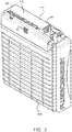
- an exemplary electrochemical cell 100 comprises a housing 110 for retaining a liquid electrolyte, an air inlet 40 and an exhaust or vent 45.
- the electrochemical cell also comprises terminals 44 for coupling to a load and/or power supply.
- a cover 111 extends over the cell.
- a mist elimination system 80 is configured to reduce and/or eliminate mist 128 that evolves from the surface of the ionically conductive medium 124, the electrolyte 126, within the cell chamber 120 due to bubbling of gasses to the surface, and to prevent or substantially prevent leakage of the electrolyte in the event of an upset.
- the mist elimination system conserves moisture within the interior chamber 122 of the electrochemical cell 100 by preventing or substantially preventing escape of the mist 128 and through reaction of hydrogen to produce water.
- a pressure relief valve 94 configured to relieve pressure from within the cell chamber 120 when required, such as when the pressure within the cell chamber exceeds a threshold pressure.
- the mist eliminator system comprises a spill prevention device 82, a safety vent 83, that is in communication with the interior chamber 122 of the cell housing 110, and therefore exposed to the ionically conductive medium 124 and/or gas space there above.
- the exemplary safety vent comprises a tortuous path conduit 99 that will slow the transfer of any liquid electrolyte to the downstream portions of the mist eliminator system.
- a tortuous path conduit may be a relatively small conduit that spirals or traverses back and forth to create an extended conduit length between the interior opening 95 and the exterior opening 96.
- a filter 85 is configured downstream of the safety vent and may be a concave shaped filter that will drain absorbed ionically conductive medium back into the anode chamber, as described in U.S. Patent No. 9,269,998 , Concave Gas Vent For Electrochemical Cell, to Fluidic Inc.
- the exemplary mist elimination system comprises a hydrogen recombination portion 86, with a hydrogen recombination catalyst 87 that reacts with any hydrogen to form water.
- the catalyst may be configured on a support material, such as particles or surfaces of the mist elimination system that are exposed to the gas exiting the cell housing from the anode space. Air may enter in to the mist elimination system through the hydrophobic filter to provide the oxygen used for the hydrogen recombination reaction.
- a parasitic corrosion reaction at the metal anode, or water reduction reaction may occur in the cell corresponding to the equation Zn+2H 2 O->Zn(OH) 2 +H 2 , or similar reaction depending on the type of metal used in a metal-air cell.
- While such hydrogen gas may be in a much smaller quantity than the evolved oxygen, it may be appreciated that the presence of hydrogen within the cell 100 is generally undesirable.
- the exemplary mist elimination system comprises a neutralizer portion 90 comprising a neutralizer media 91, such as an acid component 92, configured to neutralize the ionically conductive medium.
- the ionically conductive medium may comprise a potassium hydroxide solution that is caustic
- a neutralizer may be a solid acid or acid combined with a support material, such as acid incorporated into and/or carbon.
- the neutralizer is configured to eliminate any reactive electrolyte that may exhaust from the anode chamber or the chamber containing the ionically conductive medium that is not captured by the mist filter material 85.
- a neutralizer may comprise an absorbent that will absorb and entrain or absorb and react with the ionically conductive media, such as silica, or a molecular sieve.
- the neutralizer may also comprise a reactive material such as a solid acid or base or a liquid acid or base entrained in a porous media such as activated carbon.
- the ionically conductive media is a base, such as potassium hydroxide
- the neutralizer may comprise one or more of the following acids: citric, oaxalic, carboxylic, sulfamic, benzoic, boric, sulfuric, hydrochloric, and nitric acid.
- the mist elimination system 80 shown in FIG. 4 also comprises a hydrophobic filter 98 that prevents or substantially prevent moisture from outside of the cell from entering into the cell and may prevent or substantially prevent any liquid from exiting through the mist elimination system.
- the hydrophobic filter may also be concave or dome-shaped to facilitate the roll-off of liquid from the exterior surface and to promote roll-off of any condensation on the interior surface.
- FIG. 5 shows a block diagram of a mist elimination system.
- potassium hydroxide, (KOH), oxygen gas (O 2 ), as well as hydrogen gas, (H 2 ) may enter into the mist elimination system.
- a spill prevention device such as a safety valve, as shown, in FIGS. 6 and 7 prevents or substantially prevents liquid ionically conductive media from freely flowing out of the cell chamber.
- the safety valve prevents or substantially prevents liquid from passing out of the cell chamber through the safety valve in the event of an upset, such as the electrochemical cell being knocked over. Downstream of the safety valve is a filter for capturing any mist that may pass through the safety valve.
- a recombination portion comprising a recombination catalyst that reacts with the hydrogen to form water.
- Oxygen may be available from the ambient environment for this reaction and may enter through the hydrophobic filter.
- a neutralizer portion that reacts with any remaining electrolyte, such as KOH, to neutralize it.
- KOH is a base and the neutralizer media may comprise an acid component that reacts with this exemplary base to neutralize it, wherein the reaction produce products that are not acidic or basic, having a pH of between 4 and 10, for example and preferably between 5 and 9.
- the neutralizer media may comprise a base.
- a hydrophobic filter Downstream of the neutralizer portion is a hydrophobic filter that prevents or substantially prevents water from the ambient environment from entering into the mist elimination system.
- the hydrophobic filter may also prevent or substantially prevent liquid, such as electrolyte, from escaping through the mist elimination system.
- the neutralizer portion and recombination portion may be interchanged in terms of position.
- a recombination portion may be configured upstream of the filter and/or upset valve in some embodiments. It is preferred to protect the recombination portion from direct exposure to the liquid electrolyte however, as this may reduce the life and effectiveness of the recombination catalyst
- a spill prevention device 82 is a safety valve 300 having a ball 302 configured with a conduit 301 that floats or moves within the conduit to allow gas to pass around the ball from the inlet 305 to the outlet 306.
- the flow of gas up and around the ball may lift the ball to allow the gas to flow around the ball, as shown in FIG. 6 .
- the liquid will force the ball 302 up against sealing seat 304 to prevent or substantially prevent the liquid from passing out of the outlet 306.
- This safety valve is therefore self-regulating and is a spill prevention valve.
- an exemplary mist elimination system 80 comprises a first mist elimination stack 81 and a second mist elimination stack 81'.
- a mist elimination stack comprises two or more components of a mist elimination system including, a spill prevention device, a recombination portion, a filter, a neutralize portion and a hydrophobic filter.
- the first mist elimination stack comprises a hydrogen recombination portion 86, a spill prevention device comprising a safety valve 300, a filter 85, a neutralizer portion 90 and a hydrophobic filter 98.
- the second mist elimination stack 81' comprises a hydrogen recombination portion 86, a filter 85, a neutralizer portion 90 and a hydrophobic filter 98.
- the two layer mist elimination system better ensures that the exhaust from the cell chamber will have reduced moisture and will be neutralized. It should be appreciated that a mist elimination system may be constructed with fewer components. For example, in some embodiments, just a filter 85 may be used, or just a neutralizer 90 may be used. The number and type of mist elimination components used can be modified based on the application, use, and intended environment where the electrochemical cell will be used.
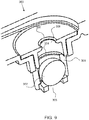
- an exemplary safety valve 300 has a ball 302 within a conduit 301 and a sealing seat 304 on a downstream end of the conduit. Fluid that condenses downstream 308 of the outlet 306 will flow down through the outlet opening, around the perimeter of the ball and through the inlet 305 back into the cell chamber, below the safety valve. Again, the ball will be forced against the sealing seat 304 and prevent (or substantially prevent) liquid from leaking from the cell chamber should the cell be tipped over.
- an exemplary safety valve 300 has a barrel 311 for retaining the ball, not shown, and a plurality of slots 312, 312', or openings from the interior of the barrel to the exterior of the barrier to allow liquid to flow freely from the downstream side back into the cell chamber.
- the slots shown extend down along a portion of the length of the barrel.
- One, two or more slots or openings may be configured in the barrel to allow liquid to flow therethrough.
- the barrel is a cylindrical member for retaining the ball and allowing the ball to move up and down or along the interior of the barrel as required for ventilation or to seal the valve when there is an upset.
Description
- This patent application claims priority to provisional patent application
62/365,924 filed on July 22, 2016 - The present disclosure is directed to mist elimination and water management systems for electrochemical cells, and more particularly to electrochemical cells comprising air breathing cathodes and utilizing a liquid ionically conductive medium.
- Many types of electrochemical cells utilize a liquid ionically conductive medium to support electrochemical reactions within the cell. Electrochemical cells may utilize an air breathing electrode coupled to a fuel electrode, comprising any suitable fuel. For example, a metal-air electrochemical cell system may comprise a plurality of cells, each having a fuel electrode serving as an anode at which metal fuel is oxidized, and an air breathing oxidant reduction electrode at which oxygen from ambient air is reduced. The liquid ionically conductive medium in such cells may communicate the oxidized/reduced ions between the electrodes.
- In various ionically conductive mediums, evaporation, electrolysis (e.g. water splitting on recharge or self-discharge, or other loss of moisture from the ionically conductive medium may be detrimental to the electrochemical cell, particularly for cells requiring water to operate. In some electrochemical cell systems, various gasses may evolve during the charging and/or discharging of the cell. Such gasses may be harmful to the cell, and may damage or impede performance of the cell. For example, an electrochemical cell may be harmed due to the evolved gasses increasing pressure within a confined volume within the cell. In some cases, the cell, and potentially its surroundings, may be harmed due to the evolution of a potentially volatile gas or combination of gasses. As such, some electrochemical cells are configured to disperse such gasses by including vents therein, so that gasses may escape into the ambient environment. For example,
U.S. patent application Ser. No. 13/566,948 , now issuedU.S. patent 9,214,708 U.S. patent application Ser. No. 13/666,864 , nowissued U.S. patent 9,269,996 - The ionically conductive medium may be an aqueous solution. Examples of suitable mediums include aqueous solutions comprising sulfuric acid, phosphoric acid, triflic acid, nitric acid, potassium hydroxide, sodium hydroxide, sodium chloride, potassium nitrate, or lithium chloride. In some embodiments, the ionically conductive medium is aqueous potassium hydroxide. In an embodiment, the ionically conductive medium may comprise an electrolyte. For example, a conventional liquid electrolyte solution may be used, or a room temperature ionic liquid may be used, as mentioned in
U.S. patent application. Ser. No. 12/776,962 , now issuedU.S. patent 8,895,197 to Arizona Board of Regents. Further examples of gas vents and alkaline electrolyte neutralisers are described inUS 9,269,998 B2 US 5,506,067 A andUS 2011/0070481 A1 . - In some electrochemical cell systems comprising liquid electrolytes, various gases evolved may entrain small amounts of liquid electrolyte therein which may be harmful to the cell and surroundings due to the emission of the resulting mist, aerosol or spray. The present application endeavors to provide an effective and improved way of capturing mists or aerosols created by the generation of gas bubbles within a volume of liquid electrolyte in an electrochemical cell and returning the liquid portion of the mist back to the main volume of the liquid electrolyte while dispersing the gas portion of the mist into the ambient environment.
- Metal-air electrochemical cells are utilized in a wide variety of environmental conditions, including very hot and dry environments. Metal-air electrochemical cells in arid environments may have limited effectiveness and/or life as a result of the loss of moisture from the liquid ionically conductive medium. It is therefore particularly important to conserve moisture within the cells when operating in arid conditions.
- The disclosure is directed to an electrochemical cell, such as a metal-air electrochemical cell having a mist elimination system as defined in the appended claims. Metal-air electrochemical cells, such as rechargeable metal-air batteries, produce a mist from the ionically conductive media, or electrolyte during normal cycling conditions. Self-discharge of the metal fuel electrode can generate hydrogen bubbles while charging of the metal fuel electrode by reducing metal fuel ions in the electrolyte is balanced by the evolution of oxygen gas on the positive electrode via the oxidation of water or hydroxide ions. The evolved gasses coalesce to form bubbles which will burst at the surface of the electrolyte and create a fine mist of electrolyte entrained in the gas effluent exiting the cell through the cell vent. Without a mist elimination system, the mist will be carried out of the cell through the exhaust vent and thereby decrease the volume of electrolyte.
- It is important to conserve the electrolyte within the cell, especially in arid environments. An exemplary mist elimination system in accordance with embodiments of this disclosure comprises a spill prevention device, a filter, a recombination portion, a neutralizer portion and a hydrophobic filter. An exemplary filter captures the mist and may return the mist to the cell. A spill prevention device, such as a tortuous path vent or valve, is used to prevent or substantially prevent liquid electrolyte from freely flowing out of the cell in the event of an upset. An exemplary recombination portion comprises a recombination catalyst that reacts with the hydrogen gas to form water. An exemplary neutralizer portion reacts with an acidic or caustic electrolyte to neutralize it. An exemplary hydrophobic filter is configured on the outside of the mist elimination system and prevents or substantially prevents liquid water from entering the cell.
- The electrochemical cell of the present disclosure may, in accordance with embodiments, further comprise a moisture, i.e. water, and carbon dioxide management system, as describe in
U.S. provisional patent application no. 62/365,866 - A variety of water management techniques are described herein.
U.S. patent application no. 15/077,341 , to Fluidic Inc., filed on March 22, 2016, entitled Water Management System In Electrochemical Cells with Vapor Return Comprising Air Electrodes describes some other water management systems and techniques. - The summary of the disclosure is provided as a general introduction to some of the embodiments of the disclosure, and is not intended to be limiting. Additional example embodiments including variations and alternative configurations of the disclosure are provided herein.
- The accompanying drawings are included to provide a further understanding of the disclosure and are incorporated in and constitute a part of this specification, illustrate embodiments of the disclosure, and together with the description serve to explain the principles of the disclosure.
-
Figure 1 depicts a schematic view of an electrochemical cell having an immersed oxidant reduction electrode. -
Figure 2 depicts a schematic view of an electrochemical cell having an oxidant reduction electrode which defines a boundary wall for the electrochemical cell. -
Figure 3 shows perspective view of an exemplary electrochemical cell. -
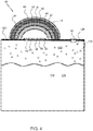
Figure 4 shows a cross-sectional schematic of an exemplary electrochemical cell having a mist elimination system. -
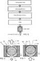
Figure 5 shows a block diagram of an exemplary mist elimination system. -
Figure 6 shows a cross-section view of an exemplary safety valve having a ball within a conduit and a sealing seat on a downstream end of the conduit. -
Figure 7 show the exemplary safety valve shown inFIG. 6 with the ball pressed against the sealing seat and preventing liquid within the conduit from passing therethrough. -
Figure 8 shows a cross-sectional view of an exemplary mist elimination system comprising a first mist elimination stack and a second mist elimination stack. -
Figure 9 shows a cross-section view of an exemplary safety valve having a ball within a conduit and a sealing seat on a downstream end of the conduit. -
Figure 10 shows a bottom, or inlet, view of an exemplary safety valve. - Corresponding reference characters indicate corresponding parts throughout the several views of the figures. The figures represent an illustration of some of the embodiments of the present disclosure and are not to be construed as limiting the scope of the disclosure in any manner. Further, the figures are not necessarily to scale, some features may be exaggerated to show details of particular components. Therefore, specific structural and functional details disclosed herein are not to be interpreted as limiting, but merely as a representative basis for teaching one skilled in the art to variously employ the present disclosure.
- As used herein, the terms "comprises," "comprising," "includes," "including," "has," "having" or any other variation thereof, are intended to cover a non-exclusive inclusion. For example, a process, method, article, or apparatus that comprises a list of elements is not necessarily limited to only those elements but may include other elements not expressly listed or inherent to such process, method, article, or apparatus. Also, use of "a" or "an" are employed to describe elements and components described herein. This is done merely for convenience and to give a general sense of the scope of the disclosure. This description should be read to include one or at least one and the singular also includes the plural unless it is obvious that it is meant otherwise.
- Certain exemplary embodiments of the present disclosure are described herein and are illustrated in the accompanying figures. The embodiments described are only for purposes of illustrating the present disclosure and should not be interpreted as limiting the scope of the disclosure. Other embodiments of the disclosure, and certain modifications, combinations and improvements of the described embodiments, will occur to those skilled in the art and all such alternate embodiments, combinations, modifications, improvements are within the scope of the appended claims. The present invention is defined in the appended claims.
- An exemplary mist elimination system in accordance with embodiments of this disclosure is configured to control the loss of liquid ionically conductive medium, such as an electrolyte, from the electrochemical cell, which may be in the form of a mist or cell gas or vapor. A mist elimination system may comprise a safety vent, baffle or valve, a filter, a hydrogen recombination catalyst, a neutralizer and a hydrophobic filter or any combination thereof, for example. An exemplary mist elimination system in accordance with embodiments of this disclosure prevents or substantially prevents leaks of a liquid ionically conductive medium, or electrolyte in the event of an upset of the cell, and conserves moisture by draining captured moisture as well as chemically formed water, back into the cell.
- In an exemplary embodiment, a mist elimination system comprises a spill prevention device, such as a safety vent, baffle or valve, to prevent or substantially prevent liquid from leaking from the cell in the event of an upset. In an exemplary embodiment, a safety valve includes a spherical stop that is free to move within a conduit having a sealing seat on at least the downstream side of the valve, whereby if the cell is upset, the liquid medium therein will flow into the conduit and force the spherical stop against the spherical seat and thereby plug and stop (or substantially stop) the flow of liquid from the cell. Under normal operation however, air flows around the spherical stop to vent the cell. In another exemplary embodiment, a vent having a tortuous path conduit prevents or substantially prevents liquid electrolyte from directly leaking out of the cell and into the filter. The safety vent may comprise a conduit that spirals or otherwise traverses to prevent (or substantially prevent) and reduce any hydrostatic head on the filter and remainder of the mist elimination system in the event of an upset, wherein the cell falls and liquid electrolyte is in direct contact with the safety vent. In an embodiment, an exemplary mist elimination system, or a spill prevention device of a mist elimination system, may be closed and sealed during shipping, such as by being plugged or otherwise covered and sealed. A pressure relief valve may be configured to release pressure from within the cell during shipping as well as during operation and may be configured to open when the pressure within the cell exceeds a threshold value.
- An exemplary mist elimination system in accordance with embodiments of this disclosure comprises a filter, which may be configured downstream of the safety vent and may comprise a non-woven or woven filter media, or membrane. In an exemplary embodiment, the filter is a concave filter as described in
U.S. patent no. 9,269,998 - An exemplary filter comprises a filter body portion comprised of at least one layer so as to absorb a portion of the ionically conductive liquid or mist. The body portion is formed in a concave shape with an apex positioned towards the top of the cell in its upright orientation, and with body surfaces extending downwardly from said apex so as to drain absorbed ionically conductive medium back into the interior chamber. The body portion contains pores so as to permit permeation of the gas therethrough. The filter may be highly efficient at removing mist and vapor that passes through the safety vent, such as more than about 80% efficient, more than about 90% efficient, more than about 95% efficient, more than about 99% efficient and any range between and including the efficiency values provided.
- In an embodiment, the filter layer may be at least partially hydrophobic which may facilitate coalescence and liquid droplet drainage as discussed previously. As a non-limiting example, the filter layer may comprise a polypropylene felt. Such a material may be a non-uniform mat of random fibers formed by needle punching, in accordance with terms known in the textile arts. In various embodiments, the filter material may be in felt shape (i.e. flexible) or may be sintered to form a rigid porous layer, or be an arrangement of these materials. The
filter layer 85 may comprise any suitable material. Non-limiting examples of such material include, but are not limited to: polypropylene, polyethylene, polyesters, fluoropolymers, acrylonitrile butadiene styrene (ABS), and Noryl (i.e. modified polyphenylene ether), combinations and derivatives thereof. In some embodiments, at least a portion of the material may be modified by surface treatments (e.g. modifying the hydrophobicity/hydrophilicity). In some embodiments the filter may comprise porous metal foams, including but not limited to comprising metals such as steel, stainless steel, bronze, and copper, and may in some embodiments be coated with a metal layer such as nickel and its alloys. - An exemplary mist elimination system in accordance with embodiments of this disclosure comprises a hydrogen recombination portion comprising a recombination catalyst that reacts with hydrogen/oxygen that may be formed from self-discharging or overcharging of the cell. The hydrogen recombination catalyst may be any suitable catalyst that will react with hydrogen to form water in the presence of oxygen, or other support media. Exemplary recombination catalyst includes, but is not limited to, perovskites, spinels, precious metal based- platinum, palladium etc., MnO2, nickel or a combination of these. An exemplary recombination portion may be configured downstream of the spill prevention device and the filter to protect the recombination catalyst from direct exposure to the electrolyte liquid.
- An exemplary mist elimination system in accordance with embodiments of this disclosure comprises a neutralizer that reacts with any liquid ionically conductive medium in the gas that passes through the mist elimination system. Neutralize, as used herein, means to react the liquid ionically conductive medium, in mist or gas phase, with a neutralization media, produce products of the reaction that are near neutral pH, such as to between 4 and 10, and more preferably between 5 and 9, and even more preferably between 6 and 8, in some embodiments. For example, neutralization media comprising an acid may be used to react with any caustic electrolyte, such as potassium hydroxide, KOH. A neutralizer may comprise a solid acid, or an acid supported on carbon or other support media. An acid may be coated onto a carbon or other support material, for example. A neutralizer may be configured with granulated or powder neutralizer media and may be in the form of a packed bed. The neutralizer may be configured in a neutralizer module that is replaceable, as the neutralizer media will be consumed in the reaction with the ionically conductive media, and therefore require replenishment. An exemplary neutralizer portion may be configured downstream of the spill prevention device, the filter and the recombination portion. An exemplary neutralizer may comprise one or more of the following acids: citric, oaxalic, carboxylic, sulfamic, benzoic, boric, sulfuric, hydrochloric, and nitric acid.
- An exemplary mist elimination system in accordance with embodiments of this disclosure comprises a hydrophobic filter that may be configured at the exit of the mist elimination system, to both keep any liquid from escaping the cell through the hydrophobic filter and to prevent or substantially prevent water from getting into the cell from the environment. A hydrophobic filter may comprise a fluoropolymer, such as a microporous fluoropolymer membrane, an expanded fluoropolymer membrane such as expanded polytetrafluoroethylene (PTFE) membrane, a polymer membrane, foam, woven media or non-woven media and the like. A microporous media or membrane may have a mean flow pore size, as measured by a Coulter porometer and/or according to ASTM F 316, Standard Test Methods for Pore Size Characteristics of Membrane Filters by Bubble Point and Mean Flow Pore Test, that is less than about 5um, less than about 2um, or less than 1um. These membranes may be inherently hydrophobic or may comprise a hydrophobic coating that reduces the surface energy of the media to prevent or substantially prevent liquid water wetout.
- A mist elimination system in accordance with embodiments of this disclosure may comprise multiple layers of one or more elements including the vent baffle or valve, a filter, a hydrogen recombination catalyst, a neutralizer and a hydrophobic filter, to ensure mist elimination and in some cases to provide a factor of safety. For example, two or more layers of hydrophobic filter media may be incorporated into the mist elimination module. In another embodiment, that entire composite stack, or portion thereof is replicated in a separate layer.
- Various portions of the
electrochemical cell 100 may be of any suitable structure or composition, including but not limited to being formed from plastic, metal, resin, or combinations thereof. Accordingly, thecell 100 may be assembled in any manner, including being formed from a plurality of elements, being integrally molded, or so on. In various embodiments thecell 100 and/or thehousing 110 may include elements or arrangements from one or more ofU.S. Patent Nos. 8,168,337 ,8,309,259 ,8,491,763 ,8,492,052 ,8,659,268 ,8,877,391 ,8,895,197 ,8,906,563 ,8,911,910 ,9,269,996 9,269,998 U.S. Patent Application Publication Nos. 20100316935 ,20110070506 ,20110250512 ,20120015264 ,20120068667 ,20120202127 ,20120321969 ,20130095393 ,20130115523 , and201301 15525 . -
FIG. 1 illustrates a schematic cross sectional view of anelectrochemical cell 100. As shown, the components of theelectrochemical cell 100 may be contained at least partially in an associatedhousing 110. Thecell 100 utilizes a liquid ionicallyconductive medium 124, such as anelectrolyte 126, that is contained within thehousing 110, and is configured to circulate therein to conduct ions within thecell 100. While at times the ionically conductive medium may be generally stationary within thehousing 110, such as in a stagnant zone, it may be appreciated that thecell 100 may be configured to create a convective flow of the ionically conductive medium. In some embodiments, the flow of the ionically conductive medium may be a convective flow generated by bubbles of evolved gas in thecell 100, such as is described inU.S. Patent Application Ser. No. 13/532,374 . These bubbles may create a mist of the liquid ionically conductive medium that is carried to an exemplary mist elimination system, as described herein. - Although in the illustrated embodiment of
FIG. 1 the cell housing is configured such that theoxidant reduction electrode 150 is immersed with the oxidantreduction electrode module 160 into thecell chamber 120, it may be appreciated that in various embodiments, other configurations or arrangements of thecell 100 are also possible. For example, inFIG. 2 , another embodiment of the cell 100 (specifically,cell 100*) is presented, whereby anoxidant reduction electrode 150* defines a boundary wall for thecell chamber 120, and is sealed to a portion of ahousing 110* so as to prevent or substantially prevent seepage of ionically conductive medium therebetween. Such a configuration is generally not preferred, however, due to concerns that a failure of theoxidant reduction electrode 150* would result in leakage of the ionically conductive medium out of thecell 100*. Regardless, in some such embodiments the convective flow of the ionically conductive medium in thecell chamber 120, described in greater detail below, may be in a direction upwards and away from theoxidant reduction electrode 150*, across the top of thefuel electrode 130. - As shown in
FIG. 3 , an exemplaryelectrochemical cell 100 comprises ahousing 110 for retaining a liquid electrolyte, anair inlet 40 and an exhaust or vent 45. The electrochemical cell also comprisesterminals 44 for coupling to a load and/or power supply. A cover 111 extends over the cell. - As shown in
FIG. 4 , amist elimination system 80 is configured to reduce and/or eliminatemist 128 that evolves from the surface of the ionicallyconductive medium 124, theelectrolyte 126, within thecell chamber 120 due to bubbling of gasses to the surface, and to prevent or substantially prevent leakage of the electrolyte in the event of an upset. The mist elimination system conserves moisture within theinterior chamber 122 of theelectrochemical cell 100 by preventing or substantially preventing escape of themist 128 and through reaction of hydrogen to produce water. Also shown inFIG. 4 is apressure relief valve 94, configured to relieve pressure from within thecell chamber 120 when required, such as when the pressure within the cell chamber exceeds a threshold pressure. - The mist eliminator system comprises a
spill prevention device 82, asafety vent 83, that is in communication with theinterior chamber 122 of thecell housing 110, and therefore exposed to the ionicallyconductive medium 124 and/or gas space there above. The exemplary safety vent comprises atortuous path conduit 99 that will slow the transfer of any liquid electrolyte to the downstream portions of the mist eliminator system. A tortuous path conduit may be a relatively small conduit that spirals or traverses back and forth to create an extended conduit length between theinterior opening 95 and theexterior opening 96. - A
filter 85 is configured downstream of the safety vent and may be a concave shaped filter that will drain absorbed ionically conductive medium back into the anode chamber, as described inU.S. Patent No. 9,269,998 - The exemplary mist elimination system comprises a
hydrogen recombination portion 86, with ahydrogen recombination catalyst 87 that reacts with any hydrogen to form water. The catalyst may be configured on a support material, such as particles or surfaces of the mist elimination system that are exposed to the gas exiting the cell housing from the anode space. Air may enter in to the mist elimination system through the hydrophobic filter to provide the oxygen used for the hydrogen recombination reaction. A parasitic corrosion reaction at the metal anode, or water reduction reaction, may occur in the cell corresponding to the equation Zn+2H2O->Zn(OH)2+H2, or similar reaction depending on the type of metal used in a metal-air cell. While such hydrogen gas may be in a much smaller quantity than the evolved oxygen, it may be appreciated that the presence of hydrogen within thecell 100 is generally undesirable. In addition, it is desirable to react the hydrogen gas out of the exhaust stream from the electrochemical cell, both to prevent (or substantially prevent) egress of hydrogen from the cell and to regenerate the water lost during the corrosion reaction and return it to the cell. - The exemplary mist elimination system comprises a
neutralizer portion 90 comprising aneutralizer media 91, such as anacid component 92, configured to neutralize the ionically conductive medium. For example, the ionically conductive medium may comprise a potassium hydroxide solution that is caustic, and a neutralizer may be a solid acid or acid combined with a support material, such as acid incorporated into and/or carbon. The neutralizer is configured to eliminate any reactive electrolyte that may exhaust from the anode chamber or the chamber containing the ionically conductive medium that is not captured by themist filter material 85. A neutralizer may comprise an absorbent that will absorb and entrain or absorb and react with the ionically conductive media, such as silica, or a molecular sieve. The neutralizer may also comprise a reactive material such as a solid acid or base or a liquid acid or base entrained in a porous media such as activated carbon. If the ionically conductive media is a base, such as potassium hydroxide, the neutralizer may comprise one or more of the following acids: citric, oaxalic, carboxylic, sulfamic, benzoic, boric, sulfuric, hydrochloric, and nitric acid. - The
mist elimination system 80 shown inFIG. 4 also comprises ahydrophobic filter 98 that prevents or substantially prevent moisture from outside of the cell from entering into the cell and may prevent or substantially prevent any liquid from exiting through the mist elimination system. The hydrophobic filter may also be concave or dome-shaped to facilitate the roll-off of liquid from the exterior surface and to promote roll-off of any condensation on the interior surface. -
FIG. 5 shows a block diagram of a mist elimination system. As shown, potassium hydroxide, (KOH), oxygen gas (O2), as well as hydrogen gas, (H2), may enter into the mist elimination system. A spill prevention device such as a safety valve, as shown, inFIGS. 6 and 7 prevents or substantially prevents liquid ionically conductive media from freely flowing out of the cell chamber. The safety valve prevents or substantially prevents liquid from passing out of the cell chamber through the safety valve in the event of an upset, such as the electrochemical cell being knocked over. Downstream of the safety valve is a filter for capturing any mist that may pass through the safety valve. Downstream of the filter is a recombination portion comprising a recombination catalyst that reacts with the hydrogen to form water. Oxygen may be available from the ambient environment for this reaction and may enter through the hydrophobic filter. Downstream of the recombination portion is a neutralizer portion that reacts with any remaining electrolyte, such as KOH, to neutralize it. KOH is a base and the neutralizer media may comprise an acid component that reacts with this exemplary base to neutralize it, wherein the reaction produce products that are not acidic or basic, having a pH of between 4 and 10, for example and preferably between 5 and 9. In the event that the electrolyte is an acid, the neutralizer media may comprise a base. Downstream of the neutralizer portion is a hydrophobic filter that prevents or substantially prevents water from the ambient environment from entering into the mist elimination system. The hydrophobic filter may also prevent or substantially prevent liquid, such as electrolyte, from escaping through the mist elimination system. It is to be understood that the neutralizer portion and recombination portion may be interchanged in terms of position. In addition, a recombination portion may be configured upstream of the filter and/or upset valve in some embodiments. It is preferred to protect the recombination portion from direct exposure to the liquid electrolyte however, as this may reduce the life and effectiveness of the recombination catalyst - As shown in
FIGS. 6 and 7 , aspill prevention device 82 is asafety valve 300 having aball 302 configured with aconduit 301 that floats or moves within the conduit to allow gas to pass around the ball from theinlet 305 to theoutlet 306. The flow of gas up and around the ball may lift the ball to allow the gas to flow around the ball, as shown inFIG. 6 . When a liquid enters the safety valve however, as shown inFIG. 7 , the liquid will force theball 302 up against sealingseat 304 to prevent or substantially prevent the liquid from passing out of theoutlet 306. This safety valve is therefore self-regulating and is a spill prevention valve. - As shown in
FIG. 8 , an exemplarymist elimination system 80 comprises a firstmist elimination stack 81 and a second mist elimination stack 81'. A mist elimination stack comprises two or more components of a mist elimination system including, a spill prevention device, a recombination portion, a filter, a neutralize portion and a hydrophobic filter. The first mist elimination stack comprises ahydrogen recombination portion 86, a spill prevention device comprising asafety valve 300, afilter 85, aneutralizer portion 90 and ahydrophobic filter 98. There is a gap, or space between the firstmist elimination stack 81 and second mist elimination stacks 81'. The second mist elimination stack 81' comprises ahydrogen recombination portion 86, afilter 85, aneutralizer portion 90 and ahydrophobic filter 98. The two layer mist elimination system better ensures that the exhaust from the cell chamber will have reduced moisture and will be neutralized. It should be appreciated that a mist elimination system may be constructed with fewer components. For example, in some embodiments, just afilter 85 may be used, or just aneutralizer 90 may be used. The number and type of mist elimination components used can be modified based on the application, use, and intended environment where the electrochemical cell will be used. - As shown in
FIG. 9 , anexemplary safety valve 300 has aball 302 within aconduit 301 and a sealingseat 304 on a downstream end of the conduit. Fluid that condenses downstream 308 of theoutlet 306 will flow down through the outlet opening, around the perimeter of the ball and through theinlet 305 back into the cell chamber, below the safety valve. Again, the ball will be forced against the sealingseat 304 and prevent (or substantially prevent) liquid from leaking from the cell chamber should the cell be tipped over. - As shown in
FIG. 10 , anexemplary safety valve 300 has abarrel 311 for retaining the ball, not shown, and a plurality ofslots 312, 312', or openings from the interior of the barrel to the exterior of the barrier to allow liquid to flow freely from the downstream side back into the cell chamber. The slots shown extend down along a portion of the length of the barrel. One, two or more slots or openings may be configured in the barrel to allow liquid to flow therethrough. The barrel is a cylindrical member for retaining the ball and allowing the ball to move up and down or along the interior of the barrel as required for ventilation or to seal the valve when there is an upset. - It will be apparent to those skilled in the art that various modifications, combinations and variations can be made in the present disclosure without departing from the scope of the disclosure. Specific embodiments, features and elements described herein may be modified, and/or combined in any suitable manner. Thus, it is intended that the present disclosure cover the modifications, combinations and variations of this disclosure provided they come within the scope of the appended claims.
Claims (15)
- An electrochemical cell comprising:a cell housing comprising:i) an air chamber;ii) an air chamber air inlet;iii) an air chamber air outlet;iv) an electrolyte chamber,
an ionically conductive liquid electrolyte in the electrolyte chamber, wherein a gas space is defined in the electrolyte chamber above the electrolyte and has a cell gas;an oxidant reduction electrode for reducing a gaseous oxidant between the air chamber and the electrolyte chamber,a fuel electrode comprising a metal fuel at least partially within the electrolyte chamber;a mist elimination system configured between the electrolyte chamber and an exhaust vent to separate the cell gas from a mist comprising the ionically conductive liquid electrolyte; wherein the mist elimination system is configured above the volume of ionically conductive liquid electrolyte; the mist elimination system comprising:a spill prevention device;a hydrogen recombination portion, comprising a hydrogen recombination catalyst configured to react with hydrogen gas within the cell gas and form water;a filter body portion comprised of at least one layer of filter media for capturing said mist;a neutralizer portion comprising a neutralizer media configured to react with and neutralize the ionically conductive liquid electrolyte contained within the mist; andwherein the filter body portion contains pores to permit permeation of said cell gas therethrough, and wherein the neutralizer portion is configured downstream of the hydrogen recombination portion, the filter body portion, and the spill prevention device. - The electrochemical cell of claim 1, wherein the spill prevention device comprising a tortuous path conduit, from an inlet to an outlet, for transferring cell gas therethrough;
wherein the tortuous path conduit inlet faces the electrolyte chamber for receiving cell gas. - The electrochemical cell of claim 1, wherein the spill prevention device comprises a safety valve.
- The electrochemical cell of claim 3, wherein the safety valve comprises a ball retained within a conduit having a sealing seat on a downstream side, wherein the ball is pressed against the sealing seat to prevent liquid passage through the safety valve when liquid enters the conduit.
- The electrochemical cell of claim 1, wherein the filter body portion is formed in a concave shape with an apex directed upwardly in the cell's upright orientation, and body surface extending downwardly from said apex so as to drain absorbed ionically conductive medium back into the electrolyte chamber.
- The electrochemical cell of claim 1, wherein the water from the reaction of hydrogen with the recombination catalyst is introduced back into the cell through the spill prevention device.
- The electrochemical cell of claim 1, wherein the hydrogen recombination catalyst is selected from the group consisting of: perovskites, spinels, precious metal based- platinum, palladium etc., MnO2, Nickel and a combination thereof.
- The electrochemical cell of claim 1, wherein the hydrogen recombination portion is configured upstream of the spill prevention device.
- The electrochemical cell of claim 1, wherein the neutralizer media comprises an acid component, which may be a solid acid component.
- The electrochemical cell of claim 9, wherein the neutralizer media comprises an acid component selected from the group consisting of: citric, oaxalic, carboxylic, sulfamic, benzoic, boric, sulfuric, hydrochloric, and nitric acid.
- The electrochemical cell of claim 1, wherein the mist elimination system further comprises a hydrophobic filter configured downstream of the neutralizer portion on an exhaust end of the mist elimination system.
- The electrochemical cell of claim 11, wherein the hydrophobic filter comprises a fluoropolymer filter media, which may be an expanded microporous fluoropolymer filter media.
- The electrochemical cell of claim 1, wherein the mist elimination system comprises a first mist elimination stack and a second mist elimination stack, wherein each of the first mist elimination stack and the second mist elimination stack comprises: a hydrogen recombination portion, a filter body portion, and a neutralizer portion, wherein each filter body portion contains pores to permit permeation of said cell gas therethrough, wherein each neutralizer portion is configured downstream of the hydrogen recombination portion and the filter body portion in their respective stack, and wherein the second mist elimination stack is stacked over the first mist elimination stack.
- The electrochemical cell according to claim 1, wherein the spill prevention device comprises a safety valve comprising:a ball retained within a conduit;a sealing seat on a downstream side of said conduit,wherein the ball is pressed against the sealing seat to prevent liquid passage through the safety valve when liquid enters the conduit; and wherein the mist elimination system further comprises:a hydrophobic filter,wherein the hydrophobic filter is configured on an exhaust end of the mist elimination system;and wherein the hydrophobic filter is configured downstream of the neutralizer portion and is on an exterior of a mist elimination system.
- The electrochemical cell of claim 1, wherein the fuel electrode is positioned apart from the oxidant reduction electrode, thereby defining a gap, and wherein said ionically conductive liquid electrolyte is in the gap.
Applications Claiming Priority (2)
| Application Number | Priority Date | Filing Date | Title |
|---|---|---|---|
| US201662365924P | 2016-07-22 | 2016-07-22 | |
| PCT/US2017/043500 WO2018018037A1 (en) | 2016-07-22 | 2017-07-24 | Mist elimination system for electrochemical cells |
Publications (2)
| Publication Number | Publication Date |
|---|---|
| EP3488488A1 EP3488488A1 (en) | 2019-05-29 |
| EP3488488B1 true EP3488488B1 (en) | 2020-06-03 |
Family
ID=59687005
Family Applications (1)
| Application Number | Title | Priority Date | Filing Date |
|---|---|---|---|
| EP17755578.6A Active EP3488488B1 (en) | 2016-07-22 | 2017-07-24 | Mist elimination system for electrochemical cells |
Country Status (9)
| Country | Link |
|---|---|
| US (2) | US11228066B2 (en) |
| EP (1) | EP3488488B1 (en) |
| JP (2) | JP2019517097A (en) |
| CN (2) | CN109565097A (en) |
| AU (1) | AU2017298995B2 (en) |
| BR (1) | BR112018074575B1 (en) |
| CA (1) | CA3019358A1 (en) |
| MX (1) | MX2019000905A (en) |
| WO (1) | WO2018018037A1 (en) |
Families Citing this family (4)
| Publication number | Priority date | Publication date | Assignee | Title |
|---|---|---|---|---|
| MX2019000912A (en) | 2016-07-22 | 2019-09-27 | Nantenergy Inc | Moisture and carbon dioxide management system in electrochemical cells. |
| WO2018018037A1 (en) * | 2016-07-22 | 2018-01-25 | Fluidic, Inc. | Mist elimination system for electrochemical cells |
| JP7437676B2 (en) | 2019-12-10 | 2024-02-26 | パナソニックIpマネジメント株式会社 | Battery packs for power tools and power tools |
| CN114522021B (en) * | 2022-04-21 | 2022-08-19 | 江苏江翔光电科技有限公司 | Antifog ventilation type becomes optical welding face guard |
Family Cites Families (30)
| Publication number | Priority date | Publication date | Assignee | Title |
|---|---|---|---|---|
| CA1309134C (en) | 1987-09-25 | 1992-10-20 | Wilfrid B. O'callaghan | Metal/air battery with recirculating electrolyte |
| US5506067A (en) * | 1995-04-04 | 1996-04-09 | Aer Energy Resources, Inc. | Rechargeable electrochemical cell and cell case therefor with vent for use in internal recombination of hydrogen and oxygen |
| US6500576B1 (en) | 2000-06-28 | 2002-12-31 | The Gillette Company | Hydrogen recombination catalyst |
| CN1543685B (en) | 2001-07-18 | 2010-04-28 | 特拉维夫大学未来技术发展有限合伙公司 | Fuel cell with proton conducting membrane and with improved water and fuel management |
| DE602005017825D1 (en) | 2005-03-10 | 2009-12-31 | Eveready Battery Inc | |
| US8168337B2 (en) | 2008-04-04 | 2012-05-01 | Arizona Board Of Regents For And On Behalf Of Arizona State University | Electrochemical cell, and particularly a metal fueled cell with non-parallel flow |
| US8309259B2 (en) | 2008-05-19 | 2012-11-13 | Arizona Board Of Regents For And On Behalf Of Arizona State University | Electrochemical cell, and particularly a cell with electrodeposited fuel |
| US8491763B2 (en) | 2008-08-28 | 2013-07-23 | Fluidic, Inc. | Oxygen recovery system and method for recovering oxygen in an electrochemical cell |
| WO2010065890A1 (en) | 2008-12-05 | 2010-06-10 | Fluidic, Llc | Electrochemical cells connected in fluid flow series |
| AU2010247863C1 (en) | 2009-05-11 | 2016-05-12 | Arizona Board Of Regents Acting For And On Behalf Of Arizona State University | Metal-air low temperature ionic liquid cell |
| US20110070481A1 (en) * | 2009-09-08 | 2011-03-24 | Delta Electronics, Inc. | Protective material and energy storage module using the same |
| IN2012DN01924A (en) | 2009-09-18 | 2015-07-24 | Fluidic Inc | |
| CN102549834B (en) | 2009-10-08 | 2015-03-11 | 流体公司 | Rechargeable metal-air cell with flow management system |
| EP2537205B1 (en) | 2010-02-16 | 2014-04-30 | Fluidic, Inc. | Electrochemical cell, and particularly a cell with electro deposited fuel |
| AU2011240840A1 (en) | 2010-04-13 | 2012-11-01 | Fluidic, Inc. | Metal-air electrocemical cell with high energy efficiency mode |
| CA2802532C (en) | 2010-06-24 | 2017-06-06 | Fluidic, Inc. | Electrochemical cell with stepped scaffold fuel anode |
| CN103081180B (en) | 2010-07-19 | 2016-08-17 | 流体公司 | There is the electrochemical cell of catch tray |
| CN102403525B (en) | 2010-09-16 | 2016-02-03 | 流体公司 | There is progressive electrochemical cell system of analysing oxygen electrode/fuel electrode |
| JP5908251B2 (en) | 2010-11-17 | 2016-04-26 | フルイディック,インク.Fluidic,Inc. | Multi-mode charging of hierarchical anode |
| CN202737060U (en) | 2011-02-04 | 2013-02-13 | 流体公司 | Dispersing system and electrochemical battery system and outer shell for ionic conduction media |
| EP2721686B1 (en) | 2011-06-17 | 2018-11-28 | NantEnergy, Inc. | Ionic liquid containing sulfonate ions |
| US9214708B2 (en) | 2011-08-05 | 2015-12-15 | Fluidic, Inc. | Gas vent for electrochemical cell |
| US9444105B2 (en) | 2011-11-04 | 2016-09-13 | Fluidic, Inc. | Immersible gaseous oxidant cathode for electrochemical cell system |
| US20130115525A1 (en) | 2011-11-04 | 2013-05-09 | Fluidic, Inc. | External ptfe layer reinforcement for oxidant electrode |
| CN203225320U (en) | 2011-11-04 | 2013-10-02 | 流体公司 | Electrochemical cell system |
| US8906563B2 (en) | 2011-11-04 | 2014-12-09 | Fluidic, Inc. | Internal convection cell |
| US9269998B2 (en) * | 2013-03-13 | 2016-02-23 | Fluidic, Inc. | Concave gas vent for electrochemical cell |
| CN103400947B (en) | 2013-08-02 | 2016-02-24 | 山东瑞宇蓄电池有限公司 | Maintenance-free lead accumulator closing cap and maintenance-free lead accumulator |
| CA3015439C (en) | 2015-03-30 | 2024-01-02 | Nantenergy, Inc. | Water management system in electrochemical cells with vapor return comprising air electrodes |
| WO2018018037A1 (en) * | 2016-07-22 | 2018-01-25 | Fluidic, Inc. | Mist elimination system for electrochemical cells |
-
2017
- 2017-07-24 WO PCT/US2017/043500 patent/WO2018018037A1/en active Search and Examination
- 2017-07-24 EP EP17755578.6A patent/EP3488488B1/en active Active
- 2017-07-24 BR BR112018074575-8A patent/BR112018074575B1/en active IP Right Grant
- 2017-07-24 JP JP2018550404A patent/JP2019517097A/en active Pending
- 2017-07-24 MX MX2019000905A patent/MX2019000905A/en unknown
- 2017-07-24 AU AU2017298995A patent/AU2017298995B2/en active Active
- 2017-07-24 US US16/318,560 patent/US11228066B2/en active Active
- 2017-07-24 CN CN201780034966.9A patent/CN109565097A/en active Pending
- 2017-07-24 CA CA3019358A patent/CA3019358A1/en not_active Abandoned
- 2017-07-24 CN CN202311284454.1A patent/CN117175083A/en active Pending
-
2020
- 2020-10-08 JP JP2020170564A patent/JP6974570B2/en active Active
-
2022
- 2022-01-10 US US17/572,054 patent/US20220131213A1/en active Pending
Non-Patent Citations (1)
| Title |
|---|
| None * |
Also Published As
| Publication number | Publication date |
|---|---|
| JP2019517097A (en) | 2019-06-20 |
| US20190221907A1 (en) | 2019-07-18 |
| JP6974570B2 (en) | 2021-12-01 |
| MX2019000905A (en) | 2019-10-02 |
| BR112018074575A2 (en) | 2019-03-12 |
| BR112018074575B1 (en) | 2023-01-17 |
| US20220131213A1 (en) | 2022-04-28 |
| US11228066B2 (en) | 2022-01-18 |
| CN109565097A (en) | 2019-04-02 |
| EP3488488A1 (en) | 2019-05-29 |
| CN117175083A (en) | 2023-12-05 |
| AU2017298995B2 (en) | 2019-08-29 |
| CA3019358A1 (en) | 2018-01-25 |
| WO2018018037A1 (en) | 2018-01-25 |
| AU2017298995A1 (en) | 2018-09-27 |
| JP2021009845A (en) | 2021-01-28 |
Similar Documents
| Publication | Publication Date | Title |
|---|---|---|
| US20220131213A1 (en) | Mist elimination system for electrochemical cells | |
| US9269998B2 (en) | Concave gas vent for electrochemical cell | |
| US11664547B2 (en) | Moisture and carbon dioxide management system in electrochemical cells | |
| US10218017B2 (en) | Water management system in electrochemical cells with vapor return comprising air electrodes | |
| JP5171781B2 (en) | Passive fuel cell assembly | |
| EP3891833B1 (en) | A direct alcohol fuel cell | |
| JP4321264B2 (en) | Fuel cell and fuel cell separator | |
| JP2005353492A (en) | Fuel cell | |
| JP2006216403A (en) | Fuel cell | |
| GB2511615A (en) | Fuel cell system | |
| JP2007305502A (en) | Direct type liquid fuel battery |
Legal Events
| Date | Code | Title | Description |
|---|---|---|---|
| STAA | Information on the status of an ep patent application or granted ep patent |
Free format text: STATUS: UNKNOWN |
|
| STAA | Information on the status of an ep patent application or granted ep patent |
Free format text: STATUS: THE INTERNATIONAL PUBLICATION HAS BEEN MADE |
|
| PUAI | Public reference made under article 153(3) epc to a published international application that has entered the european phase |
Free format text: ORIGINAL CODE: 0009012 |
|
| STAA | Information on the status of an ep patent application or granted ep patent |
Free format text: STATUS: REQUEST FOR EXAMINATION WAS MADE |
|
| 17P | Request for examination filed |
Effective date: 20180918 |
|
| AK | Designated contracting states |
Kind code of ref document: A1 Designated state(s): AL AT BE BG CH CY CZ DE DK EE ES FI FR GB GR HR HU IE IS IT LI LT LU LV MC MK MT NL NO PL PT RO RS SE SI SK SM TR |
|
| AX | Request for extension of the european patent |
Extension state: BA ME |
|
| RIN1 | Information on inventor provided before grant (corrected) |
Inventor name: KRISHNAN, RAMKUMAR Inventor name: TRZEBNY, CRAIG Inventor name: KLUG, SCOTT Inventor name: HAYES, JOEL Inventor name: SAMULESON, PATRICK |
|
| DAV | Request for validation of the european patent (deleted) | ||
| DAX | Request for extension of the european patent (deleted) | ||
| GRAP | Despatch of communication of intention to grant a patent |
Free format text: ORIGINAL CODE: EPIDOSNIGR1 |
|
| STAA | Information on the status of an ep patent application or granted ep patent |
Free format text: STATUS: GRANT OF PATENT IS INTENDED |
|
| INTG | Intention to grant announced |
Effective date: 20191212 |
|
| GRAS | Grant fee paid |
Free format text: ORIGINAL CODE: EPIDOSNIGR3 |
|
| GRAJ | Information related to disapproval of communication of intention to grant by the applicant or resumption of examination proceedings by the epo deleted |
Free format text: ORIGINAL CODE: EPIDOSDIGR1 |
|
| GRAL | Information related to payment of fee for publishing/printing deleted |
Free format text: ORIGINAL CODE: EPIDOSDIGR3 |
|
| STAA | Information on the status of an ep patent application or granted ep patent |
Free format text: STATUS: REQUEST FOR EXAMINATION WAS MADE |
|
| GRAR | Information related to intention to grant a patent recorded |
Free format text: ORIGINAL CODE: EPIDOSNIGR71 |
|
| STAA | Information on the status of an ep patent application or granted ep patent |
Free format text: STATUS: GRANT OF PATENT IS INTENDED |
|
| GRAA | (expected) grant |
Free format text: ORIGINAL CODE: 0009210 |
|
| STAA | Information on the status of an ep patent application or granted ep patent |
Free format text: STATUS: THE PATENT HAS BEEN GRANTED |
|
| INTC | Intention to grant announced (deleted) | ||
| AK | Designated contracting states |
Kind code of ref document: B1 Designated state(s): AL AT BE BG CH CY CZ DE DK EE ES FI FR GB GR HR HU IE IS IT LI LT LU LV MC MK MT NL NO PL PT RO RS SE SI SK SM TR |
|
| INTG | Intention to grant announced |
Effective date: 20200428 |
|
| REG | Reference to a national code |
Ref country code: GB Ref legal event code: FG4D |
|
| REG | Reference to a national code |
Ref country code: CH Ref legal event code: EP Ref country code: AT Ref legal event code: REF Ref document number: 1277983 Country of ref document: AT Kind code of ref document: T Effective date: 20200615 |
|
| REG | Reference to a national code |
Ref country code: DE Ref legal event code: R096 Ref document number: 602017017760 Country of ref document: DE |
|
| REG | Reference to a national code |
Ref country code: LT Ref legal event code: MG4D |
|
| PG25 | Lapsed in a contracting state [announced via postgrant information from national office to epo] |
Ref country code: GR Free format text: LAPSE BECAUSE OF FAILURE TO SUBMIT A TRANSLATION OF THE DESCRIPTION OR TO PAY THE FEE WITHIN THE PRESCRIBED TIME-LIMIT Effective date: 20200904 Ref country code: NO Free format text: LAPSE BECAUSE OF FAILURE TO SUBMIT A TRANSLATION OF THE DESCRIPTION OR TO PAY THE FEE WITHIN THE PRESCRIBED TIME-LIMIT Effective date: 20200903 Ref country code: FI Free format text: LAPSE BECAUSE OF FAILURE TO SUBMIT A TRANSLATION OF THE DESCRIPTION OR TO PAY THE FEE WITHIN THE PRESCRIBED TIME-LIMIT Effective date: 20200603 Ref country code: SE Free format text: LAPSE BECAUSE OF FAILURE TO SUBMIT A TRANSLATION OF THE DESCRIPTION OR TO PAY THE FEE WITHIN THE PRESCRIBED TIME-LIMIT Effective date: 20200603 Ref country code: LT Free format text: LAPSE BECAUSE OF FAILURE TO SUBMIT A TRANSLATION OF THE DESCRIPTION OR TO PAY THE FEE WITHIN THE PRESCRIBED TIME-LIMIT Effective date: 20200603 |
|
| REG | Reference to a national code |
Ref country code: NL Ref legal event code: MP Effective date: 20200603 |
|
| PG25 | Lapsed in a contracting state [announced via postgrant information from national office to epo] |
Ref country code: BG Free format text: LAPSE BECAUSE OF FAILURE TO SUBMIT A TRANSLATION OF THE DESCRIPTION OR TO PAY THE FEE WITHIN THE PRESCRIBED TIME-LIMIT Effective date: 20200903 Ref country code: RS Free format text: LAPSE BECAUSE OF FAILURE TO SUBMIT A TRANSLATION OF THE DESCRIPTION OR TO PAY THE FEE WITHIN THE PRESCRIBED TIME-LIMIT Effective date: 20200603 Ref country code: LV Free format text: LAPSE BECAUSE OF FAILURE TO SUBMIT A TRANSLATION OF THE DESCRIPTION OR TO PAY THE FEE WITHIN THE PRESCRIBED TIME-LIMIT Effective date: 20200603 Ref country code: HR Free format text: LAPSE BECAUSE OF FAILURE TO SUBMIT A TRANSLATION OF THE DESCRIPTION OR TO PAY THE FEE WITHIN THE PRESCRIBED TIME-LIMIT Effective date: 20200603 |
|
| REG | Reference to a national code |
Ref country code: AT Ref legal event code: MK05 Ref document number: 1277983 Country of ref document: AT Kind code of ref document: T Effective date: 20200603 |
|
| PG25 | Lapsed in a contracting state [announced via postgrant information from national office to epo] |
Ref country code: NL Free format text: LAPSE BECAUSE OF FAILURE TO SUBMIT A TRANSLATION OF THE DESCRIPTION OR TO PAY THE FEE WITHIN THE PRESCRIBED TIME-LIMIT Effective date: 20200603 Ref country code: AL Free format text: LAPSE BECAUSE OF FAILURE TO SUBMIT A TRANSLATION OF THE DESCRIPTION OR TO PAY THE FEE WITHIN THE PRESCRIBED TIME-LIMIT Effective date: 20200603 |
|
| PG25 | Lapsed in a contracting state [announced via postgrant information from national office to epo] |
Ref country code: ES Free format text: LAPSE BECAUSE OF FAILURE TO SUBMIT A TRANSLATION OF THE DESCRIPTION OR TO PAY THE FEE WITHIN THE PRESCRIBED TIME-LIMIT Effective date: 20200603 Ref country code: IT Free format text: LAPSE BECAUSE OF FAILURE TO SUBMIT A TRANSLATION OF THE DESCRIPTION OR TO PAY THE FEE WITHIN THE PRESCRIBED TIME-LIMIT Effective date: 20200603 Ref country code: EE Free format text: LAPSE BECAUSE OF FAILURE TO SUBMIT A TRANSLATION OF THE DESCRIPTION OR TO PAY THE FEE WITHIN THE PRESCRIBED TIME-LIMIT Effective date: 20200603 Ref country code: AT Free format text: LAPSE BECAUSE OF FAILURE TO SUBMIT A TRANSLATION OF THE DESCRIPTION OR TO PAY THE FEE WITHIN THE PRESCRIBED TIME-LIMIT Effective date: 20200603 Ref country code: SM Free format text: LAPSE BECAUSE OF FAILURE TO SUBMIT A TRANSLATION OF THE DESCRIPTION OR TO PAY THE FEE WITHIN THE PRESCRIBED TIME-LIMIT Effective date: 20200603 Ref country code: PT Free format text: LAPSE BECAUSE OF FAILURE TO SUBMIT A TRANSLATION OF THE DESCRIPTION OR TO PAY THE FEE WITHIN THE PRESCRIBED TIME-LIMIT Effective date: 20201006 Ref country code: RO Free format text: LAPSE BECAUSE OF FAILURE TO SUBMIT A TRANSLATION OF THE DESCRIPTION OR TO PAY THE FEE WITHIN THE PRESCRIBED TIME-LIMIT Effective date: 20200603 Ref country code: CZ Free format text: LAPSE BECAUSE OF FAILURE TO SUBMIT A TRANSLATION OF THE DESCRIPTION OR TO PAY THE FEE WITHIN THE PRESCRIBED TIME-LIMIT Effective date: 20200603 |
|
| PG25 | Lapsed in a contracting state [announced via postgrant information from national office to epo] |
Ref country code: SK Free format text: LAPSE BECAUSE OF FAILURE TO SUBMIT A TRANSLATION OF THE DESCRIPTION OR TO PAY THE FEE WITHIN THE PRESCRIBED TIME-LIMIT Effective date: 20200603 Ref country code: PL Free format text: LAPSE BECAUSE OF FAILURE TO SUBMIT A TRANSLATION OF THE DESCRIPTION OR TO PAY THE FEE WITHIN THE PRESCRIBED TIME-LIMIT Effective date: 20200603 Ref country code: IS Free format text: LAPSE BECAUSE OF FAILURE TO SUBMIT A TRANSLATION OF THE DESCRIPTION OR TO PAY THE FEE WITHIN THE PRESCRIBED TIME-LIMIT Effective date: 20201003 |
|
| REG | Reference to a national code |
Ref country code: CH Ref legal event code: PL |
|
| REG | Reference to a national code |
Ref country code: DE Ref legal event code: R097 Ref document number: 602017017760 Country of ref document: DE |
|
| PG25 | Lapsed in a contracting state [announced via postgrant information from national office to epo] |
Ref country code: MC Free format text: LAPSE BECAUSE OF FAILURE TO SUBMIT A TRANSLATION OF THE DESCRIPTION OR TO PAY THE FEE WITHIN THE PRESCRIBED TIME-LIMIT Effective date: 20200603 |
|
| PLBE | No opposition filed within time limit |
Free format text: ORIGINAL CODE: 0009261 |
|
| STAA | Information on the status of an ep patent application or granted ep patent |
Free format text: STATUS: NO OPPOSITION FILED WITHIN TIME LIMIT |
|
| REG | Reference to a national code |
Ref country code: BE Ref legal event code: MM Effective date: 20200731 |
|
| PG25 | Lapsed in a contracting state [announced via postgrant information from national office to epo] |
Ref country code: LU Free format text: LAPSE BECAUSE OF NON-PAYMENT OF DUE FEES Effective date: 20200724 Ref country code: LI Free format text: LAPSE BECAUSE OF NON-PAYMENT OF DUE FEES Effective date: 20200731 Ref country code: CH Free format text: LAPSE BECAUSE OF NON-PAYMENT OF DUE FEES Effective date: 20200731 Ref country code: DK Free format text: LAPSE BECAUSE OF FAILURE TO SUBMIT A TRANSLATION OF THE DESCRIPTION OR TO PAY THE FEE WITHIN THE PRESCRIBED TIME-LIMIT Effective date: 20200603 |
|
| 26N | No opposition filed |
Effective date: 20210304 |
|
| PG25 | Lapsed in a contracting state [announced via postgrant information from national office to epo] |
Ref country code: BE Free format text: LAPSE BECAUSE OF NON-PAYMENT OF DUE FEES Effective date: 20200731 Ref country code: SI Free format text: LAPSE BECAUSE OF FAILURE TO SUBMIT A TRANSLATION OF THE DESCRIPTION OR TO PAY THE FEE WITHIN THE PRESCRIBED TIME-LIMIT Effective date: 20200603 |
|
| PG25 | Lapsed in a contracting state [announced via postgrant information from national office to epo] |
Ref country code: IE Free format text: LAPSE BECAUSE OF NON-PAYMENT OF DUE FEES Effective date: 20200724 |
|
| PG25 | Lapsed in a contracting state [announced via postgrant information from national office to epo] |
Ref country code: TR Free format text: LAPSE BECAUSE OF FAILURE TO SUBMIT A TRANSLATION OF THE DESCRIPTION OR TO PAY THE FEE WITHIN THE PRESCRIBED TIME-LIMIT Effective date: 20200603 Ref country code: MT Free format text: LAPSE BECAUSE OF FAILURE TO SUBMIT A TRANSLATION OF THE DESCRIPTION OR TO PAY THE FEE WITHIN THE PRESCRIBED TIME-LIMIT Effective date: 20200603 Ref country code: CY Free format text: LAPSE BECAUSE OF FAILURE TO SUBMIT A TRANSLATION OF THE DESCRIPTION OR TO PAY THE FEE WITHIN THE PRESCRIBED TIME-LIMIT Effective date: 20200603 |
|
| PG25 | Lapsed in a contracting state [announced via postgrant information from national office to epo] |
Ref country code: MK Free format text: LAPSE BECAUSE OF FAILURE TO SUBMIT A TRANSLATION OF THE DESCRIPTION OR TO PAY THE FEE WITHIN THE PRESCRIBED TIME-LIMIT Effective date: 20200603 |
|
| PGFP | Annual fee paid to national office [announced via postgrant information from national office to epo] |
Ref country code: FR Payment date: 20230620 Year of fee payment: 7 |
|
| PGFP | Annual fee paid to national office [announced via postgrant information from national office to epo] |
Ref country code: GB Payment date: 20230601 Year of fee payment: 7 |
|
| PGFP | Annual fee paid to national office [announced via postgrant information from national office to epo] |
Ref country code: DE Payment date: 20230531 Year of fee payment: 7 |
|
| REG | Reference to a national code |
Ref country code: GB Ref legal event code: 732E Free format text: REGISTERED BETWEEN 20240201 AND 20240207 |