EP3488215B1 - Alignment system for cuvette segments on clinical chemistry instruments - Google Patents
Alignment system for cuvette segments on clinical chemistry instruments Download PDFInfo
- Publication number
- EP3488215B1 EP3488215B1 EP17831832.5A EP17831832A EP3488215B1 EP 3488215 B1 EP3488215 B1 EP 3488215B1 EP 17831832 A EP17831832 A EP 17831832A EP 3488215 B1 EP3488215 B1 EP 3488215B1
- Authority
- EP
- European Patent Office
- Prior art keywords
- gauge
- reaction ring
- light beam
- cuvette
- photometer
- Prior art date
- Legal status (The legal status is an assumption and is not a legal conclusion. Google has not performed a legal analysis and makes no representation as to the accuracy of the status listed.)
- Active
Links
Images





Classifications
-
- G—PHYSICS
- G01—MEASURING; TESTING
- G01N—INVESTIGATING OR ANALYSING MATERIALS BY DETERMINING THEIR CHEMICAL OR PHYSICAL PROPERTIES
- G01N35/00—Automatic analysis not limited to methods or materials provided for in any single one of groups G01N1/00 - G01N33/00; Handling materials therefor
- G01N35/02—Automatic analysis not limited to methods or materials provided for in any single one of groups G01N1/00 - G01N33/00; Handling materials therefor using a plurality of sample containers moved by a conveyor system past one or more treatment or analysis stations
- G01N35/04—Details of the conveyor system
-
- G—PHYSICS
- G01—MEASURING; TESTING
- G01N—INVESTIGATING OR ANALYSING MATERIALS BY DETERMINING THEIR CHEMICAL OR PHYSICAL PROPERTIES
- G01N35/00—Automatic analysis not limited to methods or materials provided for in any single one of groups G01N1/00 - G01N33/00; Handling materials therefor
- G01N35/02—Automatic analysis not limited to methods or materials provided for in any single one of groups G01N1/00 - G01N33/00; Handling materials therefor using a plurality of sample containers moved by a conveyor system past one or more treatment or analysis stations
- G01N35/025—Automatic analysis not limited to methods or materials provided for in any single one of groups G01N1/00 - G01N33/00; Handling materials therefor using a plurality of sample containers moved by a conveyor system past one or more treatment or analysis stations having a carousel or turntable for reaction cells or cuvettes
-
- G—PHYSICS
- G01—MEASURING; TESTING
- G01N—INVESTIGATING OR ANALYSING MATERIALS BY DETERMINING THEIR CHEMICAL OR PHYSICAL PROPERTIES
- G01N21/00—Investigating or analysing materials by the use of optical means, i.e. using sub-millimetre waves, infrared, visible or ultraviolet light
- G01N21/01—Arrangements or apparatus for facilitating the optical investigation
- G01N21/13—Moving of cuvettes or solid samples to or from the investigating station
-
- G—PHYSICS
- G01—MEASURING; TESTING
- G01N—INVESTIGATING OR ANALYSING MATERIALS BY DETERMINING THEIR CHEMICAL OR PHYSICAL PROPERTIES
- G01N21/00—Investigating or analysing materials by the use of optical means, i.e. using sub-millimetre waves, infrared, visible or ultraviolet light
- G01N21/17—Systems in which incident light is modified in accordance with the properties of the material investigated
- G01N21/25—Colour; Spectral properties, i.e. comparison of effect of material on the light at two or more different wavelengths or wavelength bands
- G01N21/251—Colorimeters; Construction thereof
- G01N21/253—Colorimeters; Construction thereof for batch operation, i.e. multisample apparatus
-
- G—PHYSICS
- G01—MEASURING; TESTING
- G01N—INVESTIGATING OR ANALYSING MATERIALS BY DETERMINING THEIR CHEMICAL OR PHYSICAL PROPERTIES
- G01N21/00—Investigating or analysing materials by the use of optical means, i.e. using sub-millimetre waves, infrared, visible or ultraviolet light
- G01N21/01—Arrangements or apparatus for facilitating the optical investigation
- G01N21/13—Moving of cuvettes or solid samples to or from the investigating station
- G01N2021/135—Sample holder displaceable
-
- G—PHYSICS
- G01—MEASURING; TESTING
- G01N—INVESTIGATING OR ANALYSING MATERIALS BY DETERMINING THEIR CHEMICAL OR PHYSICAL PROPERTIES
- G01N35/00—Automatic analysis not limited to methods or materials provided for in any single one of groups G01N1/00 - G01N33/00; Handling materials therefor
- G01N35/02—Automatic analysis not limited to methods or materials provided for in any single one of groups G01N1/00 - G01N33/00; Handling materials therefor using a plurality of sample containers moved by a conveyor system past one or more treatment or analysis stations
- G01N35/04—Details of the conveyor system
- G01N2035/0439—Rotary sample carriers, i.e. carousels
- G01N2035/0444—Rotary sample carriers, i.e. carousels for cuvettes or reaction vessels
-
- G—PHYSICS
- G01—MEASURING; TESTING
- G01N—INVESTIGATING OR ANALYSING MATERIALS BY DETERMINING THEIR CHEMICAL OR PHYSICAL PROPERTIES
- G01N35/00—Automatic analysis not limited to methods or materials provided for in any single one of groups G01N1/00 - G01N33/00; Handling materials therefor
- G01N35/02—Automatic analysis not limited to methods or materials provided for in any single one of groups G01N1/00 - G01N33/00; Handling materials therefor using a plurality of sample containers moved by a conveyor system past one or more treatment or analysis stations
- G01N35/04—Details of the conveyor system
- G01N2035/0474—Details of actuating means for conveyors or pipettes
- G01N2035/0491—Position sensing, encoding; closed-loop control
Definitions
- the present invention relates generally to methods, systems, and apparatuses for aligning cuvette segments on clinical chemistry instruments.
- the technology described herein may be integrated into, for example, automated in-vitro diagnostics (IVD) systems to ensure optimal cuvette placement for performing photometric measurements.
- IVD automated in-vitro diagnostics
- IVD allows labs to assist in the diagnosis of disease based on assays performed on patient fluid samples.
- IVD includes various types of analytical tests and assays related to patient diagnosis and therapy that can be performed by analysis of a liquid sample taken from a patient's bodily fluids, or abscesses. These assays are typically conducted with automated clinical chemistry analyzers ("analyzers") onto which fluid containers, such as tubes or vials, containing patient samples, have been loaded.
- analyzers automated clinical chemistry analyzers
- One component of the analyzer system is a reaction turntable that includes one or more reaction rings.
- Each reaction ring is arranged into multiple segments, with each segment containing multiple reaction vessels or "cuvettes.”
- Photometer readings are taken at uniform spacing to calculate absorbance measurement in each cuvette.
- the cuvette In order to acquire precise measurements, the cuvette must be properly aligned to the photometer light beam.
- cuvettes are adjusted vertically by adding shims to align with the top of the cuvette segment mounting ring surface with the screw head. This adjustment requires technique, and does not account for additional tolerances of the segment and cuvettes. Moreover, such adjustments are typically made by visual inspection of the beam on the cuvette window, which does not provide optimum positioning of the window.
- US4676952 A discloses a photometric analyzer comprising a rotor (7) with a plurality of guiding chambers (9) in which insert elements (11) are inserted. A cuvette (15) is included in each insert element. Horizontal/radial alignment of the cuvette (15) with the light beam path (17) of the photometer (95) is ensured by a positioning pin (57) and a positioning though (59).
- US3555284 A discloses a photometric analyzer where the cuvettes (9) with a transparent window are radially aligned with the light beam axis of the photometer (18-25).
- GB2083617 A discloses a photometric analyzer where the cuvettes (32) with a transparent window are radially aligned with the light beam axis (54) of the photometer (50, 52).
- Embodiments of the present invention address and overcome one or more of the above shortcomings and drawbacks by providing methods, systems, and apparatuses related to the alignment of cuvette segment on clinical chemistry analyzers.
- the reaction ring is part of the analyzer to which first the vertical gauge is applied to set the proper height by inserting the light beam gauge into the aperture and rotating the reaction ring to see if the light beam gauge will engage the end slot in the ends of the reaction ring gauge. Once that height is properly adjusted, the ring may be indexed with the light beam gauge retracted to make sure that it will still be able to insert into the holes equally spaced across the reaction ring gauge after each index.
- the reaction ring gauge is then removed and replaced with a production cuvette segment assembly which then is marked in the optical window areas by rotating the light beam gauge against the actual cuvette windows so it can be visually inspected upon removal to confirm proper alignment for performing measurements during production.
- a method for aligning a reaction ring in an analyzer system according to independent claim 1 is provided.
- a system for aligning a reaction ring in an analyzer system according to independent claim 5 is provided.
- the technology described herein provides a visual marking on the cuvette window to verify the light beam position.
- a lamp mounting bracket provides the location of the light beam used for photometric analysis. This lamp mounting bracket is utilized to hold a light beam gauge in position to provide marking on a cuvette window.
- the process described herein enhances IVD system results by ensuring that the reaction ring is set at the optimum height to be used with all future cuvette segments that are put on the instrument. This process may be performed, for example, during manufacturing to set the height of the reaction ring when the instrument is built or in the event that the radial drive motor needs to be replaced in the field.
- FIG. 1 illustrates a cross-section view of a system 100 that may be used to perform cuvette segment alignment, according to some embodiments.
- the system 100 adjusts cuvettes to proper vertical positioning for reading by an IVD detection system. This system 100 decreases the difficulty of precisely locating the cuvette window with the light beam, especially in configurations where the cuvettes cannot be clearly seen from above the reaction ring.
- Cuvette segment alignment is performed using a variety of components in the system 100. These components include a gauge vertical reaction ring 105 configured with openings that receive a light beam gauge 110. A more detailed view of the light beam gauge 110 is shown in FIG. 6B . As shown in FIG. 6B , the light beam gauge 110 is a cylindrical object with a sharp edge on the end. As described below, the sharp end may be used to create a circular spot on the cuvette window when manually rotated with a small force applied against the cuvette.
- the light beam gauge 110 may generally be constructed out of any material capable of scoring (i.e., cutting or scratching) the cuvette window to make the circular spot.
- the light beam gauge 110 resides in an aperture photometer 120 within a lamp mounting bracket 115.
- the aperture photometer 120 is secured to the lamp mounting bracket 115 using a ring lock aperture 125.
- the design of the lamp mounting bracket 115, the aperture photometer 120, and the ring lock aperture 125 are shown in further detail in FIGS. 6A, 6C, and 6D , respectively.
- the lamp mounting bracket 115 provides the location of the light beam used for photometric analysis.
- the lamp mounting bracket 115 holds the aperture photometer 120 at a height corresponding to the actual light source center axis 125 of the photometer. At this height, the aperture photometer 120 allows for the insertion and rotation of the light beam gauge 110 to create the circular spot on the cuvette window.
- FIG. 2A is a top down view of electromechanical systems for an exemplary analyzer module 260 for use with some embodiments.
- Sample arm 223 is responsible for aspirating a sample portion prepared by dilution mixer 221, moving above a reaction ring 225, and dispensing that sample portion into a cuvette.
- reaction ring 225 can include a plurality of concentric rings having cuvettes with samples and reagents. These rings can be moved relative to one another to allow reagents to be aspirated and dispensed into reaction vessels containing samples. In some embodiments, a single ring is used.
- the reaction ring may include cuvette segment assembly and/or a gauge vertical reaction ring, as described below with respect to FIGS. 2B - 2D .
- Reagents can be added before the sample arrives, or after the sample arrives via reagent arm 235 or reagent arm 255.
- Reagent servers 230 and 235 include a variety of different reagents, allowing a variety of tests to be performed by analyzer module 260.
- Reagent arms 253 and 255 move aliquots of reagents from reagent server 235 or reagent server 230, respectively. These aliquots are then dispensed into cuvettes in reaction ring 225.
- Reaction ring 225 moves cuvettes in a predetermined sequence such that each cuvette reaches reagent mixer 240 or sample mixer 245 for mixing. Once mixed, the reaction between the sample and reagent proceeds in the cuvette.
- Reaction ring 225 rotates to allow photometer 250 to take photometric measurements of the reaction at predetermined times.
- FIG. 2B shows a view cuvette segment assembly 200 with cuvettes installed (e.g., cuvettes 205).
- Each cuvette is a small tube designed to hold samples for spectroscopic experiments.
- Cuvettes are sealed at one end and have a circular cross-section or, as illustrated in FIG. 2B the cross section may be square or rectangular. Square or rectangular cross-sections are generally used to avoid refraction artefacts while making photometric measurements.
- Various materials may be used to construct cuvettes including, without limitation, optical glass, UV quartz, IR quartz, or sapphire.
- FIG. 2C shows an alternative view of the shown in FIG. 2B . The view provided in FIG.
- each cuvette includes a small window referred to herein as the "optical area” (e.g., optical area 210).
- optical area e.g., optical area 210.
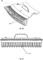
- FIG. 2D provides a gauge vertical reaction ring 210 that is designed to represent a cuvette segment assembly holding cuvettes (e.g., as shown in FIGS. 2A and 2B ).
- the gauge vertical reaction ring 210 includes a plurality of openings (e.g., openings 215) at positions corresponding to the optical areas of the cuvettes (see FIG. 2B ).
- the openings are located along a line at the front of the gauge vertical reaction ring 210.
- Each end of the line of openings includes a slot (i.e., end slots 220A and 220B).
- the light beam gauge (see FIGS. 1 and 6B ) is insertable into the openings of the gauge vertical reaction ring and each slot.
- these openings allow the light beam gauge to pass through the gauge vertical reaction ring when the reaction ring is adjusted to the proper height.
- the gauge vertical reaction ring 210 is rotated manually or automatically until the light beam gauge engages (i.e., enters) one of the end slots. At this point, the light beam gauge is retracted. Then, the gauge vertical reaction ring 210 is rotated by indexing the reaction ring by a predetermined amount stored in the software of the system 100. During this indexing, the light beam gauge is manually inserted into each of the openings. This assures that the light beam gauge enters the optical area of each individual cuvette in the cuvette segment assembly.
- the gauge vertical reaction ring 210 is removed from the reaction ring and replaced with a cuvette segment assembly holding cuvettes. Then, for each cuvette in the assembly, the light beam gauge is manually inserted into the aperture photometer and rotated against the optical area of the cuvette to create a visual marking (e.g., a small circle).
- a motor may be added to automate insertion as well as other actions performed with the light beam gauge (e.g. rotation).
- FIGS. 3 - 5 provide additional views of the IVD system with a gauge vertical reaction ring 320 installed, according to some embodiments.
- FIG. 3 shows a cross-section of a cuvette alignment system, according to some embodiments of the present invention.
- an aperture photometer 315 is attached to the lamp mounting bracket 307 to hold a light beam gauge 305 in place at the light source center axis (see FIG. 1 ).
- the ring lock aperture 310 shown in FIG. 3 holds the aperture photometer 315 in place, allowing the light beam gauge 305 to score cuvettes in the gauge vertical reaction ring 320 accordingly.
- One or more shims may be added, as needed, to provide proper alignment of the gauge vertical reaction ring 320 with the light beam gauge 305.
- the gauge vertical reaction ring 320 is properly aligned, the light beam gauge 305 is inserted into the openings and end slots (see FIG. 2D ) in the gauge vertical reaction ring 320.
- FIG. 4 shows the final configuration of the system after the cuvette segment assembly 500 has moved into the location where measurements will be performed.
- FIG. 7 shows a flowchart which describes a method of aligning a reaction ring in an analyzer system using a gauge vertical reaction ring at least one end slot, according to some embodiments.
- a light beam gauge is inserted into an aperture operable to hold the light beam gauge at a height corresponding to a photometer included in the analyzer system (e.g., the light source center axis of the photometer).
- the gauge vertical reaction ring is placed on the reaction ring of the analyzer.
- the gauge vertical reaction ring is rotated on the reaction ring until the light beam gauge engages the end slot to confirm alignment of the reaction ring with the photometer.
- the light beam gauge is retracted from the aperture, for example, by a user manually pulling the light beam gauge in a direction away from the reaction ring.
- the light gauge can be removed altogether or simply retracted until the gauge vertical reaction ring can freely rotate without contacting the light beam gauge.
- the gauge vertical reaction ring is rotated by indexing the reaction ring using the analyzer system software. During rotation of the gauge vertical reaction ring, as shown in step 730, the light beam gauge is inserted into each of the openings of the gauge vertical reaction ring to further confirm alignment of the reaction ring with the photometer during the indexing procedure.
- the vertical reaction ring is replaced on the reaction ring with a cuvette segments assembly comprising a plurality of cuvettes (see FIGS. 2A and 2B ).
- the sharp point of the light beam gauge is rotated against an optical area of the cuvette to create a visual marking on the optical area.
- the embodiments of the present disclosure may be implemented with a combination of hardware and software.
- functionality employed by the embodiments of the present disclosure may be included in an article of manufacture (e.g., one or more computer program products) having, for example, computer-readable, non-transitory media.
- the media has embodied therein, for instance, computer readable program code for providing and facilitating the mechanisms of the embodiments of the present disclosure.
- the article of manufacture can be included as part of a computer system or sold separately.
- An activity performed automatically is performed in response to one or more executable instructions or device operations without user direct initiation of the activity.
Landscapes
- Chemical & Material Sciences (AREA)
- Physics & Mathematics (AREA)
- General Physics & Mathematics (AREA)
- Immunology (AREA)
- Life Sciences & Earth Sciences (AREA)
- Analytical Chemistry (AREA)
- Biochemistry (AREA)
- General Health & Medical Sciences (AREA)
- Pathology (AREA)
- Health & Medical Sciences (AREA)
- Chemical Kinetics & Catalysis (AREA)
- Spectroscopy & Molecular Physics (AREA)
- Optical Measuring Cells (AREA)
- Automatic Analysis And Handling Materials Therefor (AREA)
- Investigating Or Analysing Materials By Optical Means (AREA)
- Investigating Or Analysing Materials By The Use Of Chemical Reactions (AREA)
Description
- This application claims the benefit of
U.S. Provisional Application Serial No. 62/365,298 filed July 21, 2016 - The present invention relates generally to methods, systems, and apparatuses for aligning cuvette segments on clinical chemistry instruments. The technology described herein may be integrated into, for example, automated in-vitro diagnostics (IVD) systems to ensure optimal cuvette placement for performing photometric measurements.
- IVD allows labs to assist in the diagnosis of disease based on assays performed on patient fluid samples. IVD includes various types of analytical tests and assays related to patient diagnosis and therapy that can be performed by analysis of a liquid sample taken from a patient's bodily fluids, or abscesses. These assays are typically conducted with automated clinical chemistry analyzers ("analyzers") onto which fluid containers, such as tubes or vials, containing patient samples, have been loaded.
- One component of the analyzer system is a reaction turntable that includes one or more reaction rings. Each reaction ring is arranged into multiple segments, with each segment containing multiple reaction vessels or "cuvettes." Photometer readings are taken at uniform spacing to calculate absorbance measurement in each cuvette. In order to acquire precise measurements, the cuvette must be properly aligned to the photometer light beam. In conventional systems, cuvettes are adjusted vertically by adding shims to align with the top of the cuvette segment mounting ring surface with the screw head. This adjustment requires technique, and does not account for additional tolerances of the segment and cuvettes. Moreover, such adjustments are typically made by visual inspection of the beam on the cuvette window, which does not provide optimum positioning of the window.
- Various techniques are known in the art for aligning cuvette segments on automated clinical chemistry analyzers.
US4676952 A discloses a photometric analyzer comprising a rotor (7) with a plurality of guiding chambers (9) in which insert elements (11) are inserted. A cuvette (15) is included in each insert element. Horizontal/radial alignment of the cuvette (15) with the light beam path (17) of the photometer (95) is ensured by a positioning pin (57) and a positioning though (59).US3555284 A discloses a photometric analyzer where the cuvettes (9) with a transparent window are radially aligned with the light beam axis of the photometer (18-25). Likewise,GB2083617 A - Embodiments of the present invention address and overcome one or more of the above shortcomings and drawbacks by providing methods, systems, and apparatuses related to the alignment of cuvette segment on clinical chemistry analyzers. The reaction ring is part of the analyzer to which first the vertical gauge is applied to set the proper height by inserting the light beam gauge into the aperture and rotating the reaction ring to see if the light beam gauge will engage the end slot in the ends of the reaction ring gauge. Once that height is properly adjusted, the ring may be indexed with the light beam gauge retracted to make sure that it will still be able to insert into the holes equally spaced across the reaction ring gauge after each index. The reaction ring gauge is then removed and replaced with a production cuvette segment assembly which then is marked in the optical window areas by rotating the light beam gauge against the actual cuvette windows so it can be visually inspected upon removal to confirm proper alignment for performing measurements during production.
- According to one aspect of the present invention, a method for aligning a reaction ring in an analyzer system according to independent claim 1 is provided.
- According to another aspect of the present invention, a system for aligning a reaction ring in an analyzer system according to independent claim 5 is provided.
- Advantageous embodiments of the present invention are put forward in the dependent claims 2-4 and 6-8.
- Additional features and advantages of the invention will be made apparent from the following detailed description of illustrative embodiments that proceeds with reference to the accompanying drawings.
- The foregoing and other aspects of the present invention are best understood from the following detailed description when read in connection with the accompanying drawing. For the purpose of illustrating the invention, there is shown in the drawing embodiments that are presently preferred, it being understood, however, that the invention is not limited to the specific instrumentalities disclosed. Included in the drawings are the following Figures.
-
FIG. 1 illustrates a system that may be used to perform cuvette segment alignment, according to some embodiments; -
FIG. 2A is a top down view of electromechanical systems for an exemplary analyzer module for use with some embodiments; -
FIG. 2B shows a view cuvette segment assembly with cuvettes installed; -
FIG. 2C shows an alternative view of the shown inFIG. 2B ; -
FIG. 2D provides a gauge vertical reaction ring that is designed to represent a cuvette segment assembly holding cuvettes; -
FIG. 3 shows a cross-section of a cuvette alignment system indicating placement of a light beam gauge, according to some embodiments of the present invention; -
FIG. 4 shows a cross-section of a cuvette alignment system indicating rotation of a light beam gauge against a cuvette, according to some embodiments of the present invention; -
FIG. 5 shows a cross-section of a cuvette alignment system indicating placement of a reaction ring segment assembly, according to some embodiments of the present invention; -
FIG. 6A provides an illustration of a bracket light source photo used in some embodiments of the present invention; -
FIG. 6B provides an illustration of a light beam gauge used in some embodiments of the present invention; -
FIG. 6C provides an illustration of an aperture photometer used in some embodiments of the present invention; -
FIG. 6D provides an illustration of a ring lock aperture used in some embodiments of the present invention; and -
FIG. 7 shows a flowchart which describes a method of aligning a reaction ring in an analyzer system using a gauge vertical reaction ring at least one end slot, according to some embodiments. - The following disclosure describes the present invention according to several embodiments directed at methods, systems, and apparatuses related to the alignment of cuvette segment on clinical chemistry instruments. Briefly, the technology described herein provides a visual marking on the cuvette window to verify the light beam position. A lamp mounting bracket provides the location of the light beam used for photometric analysis. This lamp mounting bracket is utilized to hold a light beam gauge in position to provide marking on a cuvette window. Thus, the process described herein enhances IVD system results by ensuring that the reaction ring is set at the optimum height to be used with all future cuvette segments that are put on the instrument. This process may be performed, for example, during manufacturing to set the height of the reaction ring when the instrument is built or in the event that the radial drive motor needs to be replaced in the field.
-
FIG. 1 illustrates a cross-section view of a system 100 that may be used to perform cuvette segment alignment, according to some embodiments. The system 100 adjusts cuvettes to proper vertical positioning for reading by an IVD detection system. This system 100 decreases the difficulty of precisely locating the cuvette window with the light beam, especially in configurations where the cuvettes cannot be clearly seen from above the reaction ring. - Cuvette segment alignment is performed using a variety of components in the system 100. These components include a gauge vertical reaction ring 105 configured with openings that receive a light beam gauge 110. A more detailed view of the light beam gauge 110 is shown in
FIG. 6B . As shown inFIG. 6B , the light beam gauge 110 is a cylindrical object with a sharp edge on the end. As described below, the sharp end may be used to create a circular spot on the cuvette window when manually rotated with a small force applied against the cuvette. The light beam gauge 110 may generally be constructed out of any material capable of scoring (i.e., cutting or scratching) the cuvette window to make the circular spot. - The light beam gauge 110 resides in an aperture photometer 120 within a lamp mounting bracket 115. The aperture photometer 120 is secured to the lamp mounting bracket 115 using a ring lock aperture 125. The design of the lamp mounting bracket 115, the aperture photometer 120, and the ring lock aperture 125 are shown in further detail in
FIGS. 6A, 6C, and 6D , respectively. In operation of the system 100 shown inFIG. 1 , the lamp mounting bracket 115 provides the location of the light beam used for photometric analysis. The lamp mounting bracket 115 holds the aperture photometer 120 at a height corresponding to the actual light source center axis 125 of the photometer. At this height, the aperture photometer 120 allows for the insertion and rotation of the light beam gauge 110 to create the circular spot on the cuvette window. -
FIG. 2A is a top down view of electromechanical systems for anexemplary analyzer module 260 for use with some embodiments.Sample arm 223 is responsible for aspirating a sample portion prepared bydilution mixer 221, moving above areaction ring 225, and dispensing that sample portion into a cuvette. In some embodiments,reaction ring 225 can include a plurality of concentric rings having cuvettes with samples and reagents. These rings can be moved relative to one another to allow reagents to be aspirated and dispensed into reaction vessels containing samples. In some embodiments, a single ring is used. The reaction ring may include cuvette segment assembly and/or a gauge vertical reaction ring, as described below with respect toFIGS. 2B - 2D . Reagents can be added before the sample arrives, or after the sample arrives viareagent arm 235 orreagent arm 255.Reagent servers analyzer module 260.Reagent arms reagent server 235 orreagent server 230, respectively. These aliquots are then dispensed into cuvettes inreaction ring 225.Reaction ring 225 moves cuvettes in a predetermined sequence such that each cuvette reachesreagent mixer 240 orsample mixer 245 for mixing. Once mixed, the reaction between the sample and reagent proceeds in the cuvette.Reaction ring 225 rotates to allowphotometer 250 to take photometric measurements of the reaction at predetermined times. -
FIG. 2B shows a viewcuvette segment assembly 200 with cuvettes installed (e.g., cuvettes 205). Each cuvette is a small tube designed to hold samples for spectroscopic experiments. Cuvettes are sealed at one end and have a circular cross-section or, as illustrated inFIG. 2B the cross section may be square or rectangular. Square or rectangular cross-sections are generally used to avoid refraction artefacts while making photometric measurements. Various materials may be used to construct cuvettes including, without limitation, optical glass, UV quartz, IR quartz, or sapphire.FIG. 2C shows an alternative view of the shown inFIG. 2B . The view provided inFIG. 2B illustrates that the lower portion of each cuvette includes a small window referred to herein as the "optical area" (e.g., optical area 210). During the photometric measurement, light emitted by the light beam gauge is directed to the optical area of the cuvette. -
FIG. 2D provides a gaugevertical reaction ring 210 that is designed to represent a cuvette segment assembly holding cuvettes (e.g., as shown inFIGS. 2A and2B ). As shown inFIG. 2D , the gaugevertical reaction ring 210 includes a plurality of openings (e.g., openings 215) at positions corresponding to the optical areas of the cuvettes (seeFIG. 2B ). As shown inFIG. 2D , the openings are located along a line at the front of the gaugevertical reaction ring 210. Each end of the line of openings includes a slot (i.e.,end slots FIGS. 1 and6B ) is insertable into the openings of the gauge vertical reaction ring and each slot. - Thus, these openings allow the light beam gauge to pass through the gauge vertical reaction ring when the reaction ring is adjusted to the proper height. In operation, the gauge
vertical reaction ring 210 is rotated manually or automatically until the light beam gauge engages (i.e., enters) one of the end slots. At this point, the light beam gauge is retracted. Then, the gaugevertical reaction ring 210 is rotated by indexing the reaction ring by a predetermined amount stored in the software of the system 100. During this indexing, the light beam gauge is manually inserted into each of the openings. This assures that the light beam gauge enters the optical area of each individual cuvette in the cuvette segment assembly. Next, the gaugevertical reaction ring 210 is removed from the reaction ring and replaced with a cuvette segment assembly holding cuvettes. Then, for each cuvette in the assembly, the light beam gauge is manually inserted into the aperture photometer and rotated against the optical area of the cuvette to create a visual marking (e.g., a small circle). As an alternative to manual insertion, in some embodiments, a motor may be added to automate insertion as well as other actions performed with the light beam gauge (e.g. rotation). -
FIGS. 3 - 5 provide additional views of the IVD system with a gauge vertical reaction ring 320 installed, according to some embodiments.FIG. 3 shows a cross-section of a cuvette alignment system, according to some embodiments of the present invention. In this example, an aperture photometer 315 is attached to thelamp mounting bracket 307 to hold alight beam gauge 305 in place at the light source center axis (seeFIG. 1 ). The ring lock aperture 310 shown inFIG. 3 holds the aperture photometer 315 in place, allowing thelight beam gauge 305 to score cuvettes in the gauge vertical reaction ring 320 accordingly. One or more shims may be added, as needed, to provide proper alignment of the gauge vertical reaction ring 320 with thelight beam gauge 305. Once the gauge vertical reaction ring 320 is properly aligned, thelight beam gauge 305 is inserted into the openings and end slots (seeFIG. 2D ) in the gauge vertical reaction ring 320. - Next, with the cuvette segment in place, the
light beam gauge 305 can be rotated against the cuvette to score the optical area. This rotation, along with the placement of the cuvette segment 405, is illustrated inFIG. 4 . As shown, the light 410 emitted by thelight beam gauge 305 travels through the optical area 415 of the cuvette that is currently aligned with thelight beam gauge 305. Finally,FIG. 5 shows the final configuration of the system after the cuvette segment assembly 500 has moved into the location where measurements will be performed. - To summarize the techniques described above,
FIG. 7 shows a flowchart which describes a method of aligning a reaction ring in an analyzer system using a gauge vertical reaction ring at least one end slot, according to some embodiments. Starting at step 705 a light beam gauge is inserted into an aperture operable to hold the light beam gauge at a height corresponding to a photometer included in the analyzer system (e.g., the light source center axis of the photometer). Atstep 710, the gauge vertical reaction ring is placed on the reaction ring of the analyzer. Next, atstep 715, the gauge vertical reaction ring is rotated on the reaction ring until the light beam gauge engages the end slot to confirm alignment of the reaction ring with the photometer. - Continuing with reference to
FIG. 7 , atstep 720, the light beam gauge is retracted from the aperture, for example, by a user manually pulling the light beam gauge in a direction away from the reaction ring. The light gauge can be removed altogether or simply retracted until the gauge vertical reaction ring can freely rotate without contacting the light beam gauge. Next, atstep 725, the gauge vertical reaction ring is rotated by indexing the reaction ring using the analyzer system software. During rotation of the gauge vertical reaction ring, as shown instep 730, the light beam gauge is inserted into each of the openings of the gauge vertical reaction ring to further confirm alignment of the reaction ring with the photometer during the indexing procedure. - At
step 735, the vertical reaction ring is replaced on the reaction ring with a cuvette segments assembly comprising a plurality of cuvettes (seeFIGS. 2A and2B ). Finally atstep 740, for each cuvette in the cuvette segments assembly, the sharp point of the light beam gauge is rotated against an optical area of the cuvette to create a visual marking on the optical area. - The embodiments of the present disclosure may be implemented with a combination of hardware and software. In addition, functionality employed by the embodiments of the present disclosure may be included in an article of manufacture (e.g., one or more computer program products) having, for example, computer-readable, non-transitory media. The media has embodied therein, for instance, computer readable program code for providing and facilitating the mechanisms of the embodiments of the present disclosure. The article of manufacture can be included as part of a computer system or sold separately.
- The functions and process steps herein may be performed automatically, or wholly, or partially in response to user command. An activity (including a step) performed automatically is performed in response to one or more executable instructions or device operations without user direct initiation of the activity.
Claims (8)
- A method of aligning a reaction ring (225) in an analyzer system using a gauge vertical reaction ring (210, 320) comprising at least one end slot (220A, 220B), the method comprising:inserting a light beam gauge (110, 305) into an aperture (125) operable to hold the light beam gauge (110, 305) at a height corresponding to a photometer (120, 250, 315) included in the analyzer system;rotating the gauge vertical reaction ring (210, 320) on the reaction ring (225) until the light beam gauge (110, 305) engages the end slot (220A, 220B) to confirm alignment of the reaction ring (225) with the photometer (120, 250, 315), wherein the gauge vertical reaction ring (210, 320) further comprises a plurality of openings (215);retracting the light beam gauge (110, 305) from the aperture (125);rotating the gauge vertical reaction ring (210, 320) by indexing the reaction ring (225);during rotation of the gauge vertical reaction ring (210, 320), inserting the light beam gauge (110, 305) into each of the openings (215) of the gauge vertical reaction ring (210, 320) to confirm alignment of the reaction ring (225) with the photometer (120, 250, 315), wherein the light beam gauge (110, 305) comprises a sharp point;replacing the gauge vertical reaction ring (210, 320) on the reaction ring (225) with a cuvette segment assembly (200, 500) comprising a plurality of cuvettes (205); andfor each cuvette (205) in the cuvette segment assembly (200, 500), rotating the sharp point of the light beam gauge (110, 305) against an optical area (210, 415) of the cuvette (205) to create a visual marking on the optical area (210, 415).
- The method of claim 1, wherein the light beam gauge (110, 305) is manually rotated against
the optical area (210, 415) of the cuvette (205) by a user. - The method of claim 1, wherein the indexing of the reaction ring (225) is performed automatically by the analyzer system.
- The method of claim 1, wherein the height corresponding to the photometer (120, 250, 315) corresponds to a light source center axis (125) of the photometer (120, 250, 315).
- A system (100) for aligning a reaction ring (225) in an analyzer system, the system (100) comprising:a gauge vertical reaction ring (210, 320) installable on the reaction ring (225), wherein the gauge vertical reaction ring (210, 320) comprises a plurality of openings (215) at positions corresponding to optical areas (210, 415) associated with the cuvettes (205) in a cuvette segment assembly (200, 500);a light beam gauge (110, 305) comprising an end portion insertable into the plurality of openings (215);a bracket light source photo configured to hold the light beam gauge (110, 305) at a height corresponding to a light source center axis (125) corresponding to a photometer (120, 250, 315) included in the analyzer system;an aperture photometer (120, 250, 315) configured to hold the light beam gauge (110, 305) in the bracket light source photo;wherein the gauge vertical reaction ring (210, 320) further comprises one or more end slots (220A, 220B) operable to engage the light beam gauge (110, 305) when the light beam gauge (110, 305) is placed in the bracket light source photo and the gauge vertical reaction ring (210, 320) is rotated on the reaction ring. (ring 225).
- The system (100) of claim 5, further comprising:
a ring lock aperture (125, 310) configured to secure the aperture photometer (120, 250, 315) within the bracket light source photo. - The system of claim 5, wherein the aperture photometer (120, 250, 315) is an aperture 1.5 mm photometer.
- The system of claim 5, wherein each of the plurality of openings (215) is circular.
Applications Claiming Priority (2)
| Application Number | Priority Date | Filing Date | Title |
|---|---|---|---|
| US201662365298P | 2016-07-21 | 2016-07-21 | |
| PCT/US2017/042936 WO2018017766A1 (en) | 2016-07-21 | 2017-07-19 | Alignment system for cuvette segments on clinical chemistry instruments |
Publications (3)
| Publication Number | Publication Date |
|---|---|
| EP3488215A1 EP3488215A1 (en) | 2019-05-29 |
| EP3488215A4 EP3488215A4 (en) | 2019-11-13 |
| EP3488215B1 true EP3488215B1 (en) | 2021-01-06 |
Family
ID=60992904
Family Applications (1)
| Application Number | Title | Priority Date | Filing Date |
|---|---|---|---|
| EP17831832.5A Active EP3488215B1 (en) | 2016-07-21 | 2017-07-19 | Alignment system for cuvette segments on clinical chemistry instruments |
Country Status (5)
| Country | Link |
|---|---|
| US (1) | US10545162B2 (en) |
| EP (1) | EP3488215B1 (en) |
| JP (1) | JP6749467B2 (en) |
| CN (1) | CN109477775B (en) |
| WO (1) | WO2018017766A1 (en) |
Families Citing this family (1)
| Publication number | Priority date | Publication date | Assignee | Title |
|---|---|---|---|---|
| JP7828764B2 (en) * | 2022-01-18 | 2026-03-12 | キヤノンメディカルシステムズ株式会社 | automatic analyzer |
Family Cites Families (16)
| Publication number | Priority date | Publication date | Assignee | Title |
|---|---|---|---|---|
| US3555284A (en) * | 1968-12-18 | 1971-01-12 | Norman G Anderson | Multistation, single channel analytical photometer and method of use |
| CH601791A5 (en) * | 1975-10-29 | 1978-07-14 | Battelle Memorial Institute | |
| US4123173A (en) * | 1976-06-09 | 1978-10-31 | Electro-Nucleonics, Inc. | Rotatable flexible cuvette arrays |
| US4234538A (en) * | 1977-10-28 | 1980-11-18 | Coulter Electronics, Inc. | Apparatus for monitoring chemical reactions and employing moving photometer means |
| CH637766A5 (en) | 1977-06-20 | 1983-08-15 | Coulter Electronics | PROCESS FOR CONTROLLING CHEMICAL REACTIONS OCCURRING IN SAMPLES OF LIQUIDS AND APPARATUS FOR CARRYING OUT SAID METHOD. |
| DE3314961A1 (en) * | 1983-04-25 | 1984-10-25 | Boehringer Mannheim Gmbh, 6800 Mannheim | ANALYZER FOR PHOTOMETRICALLY DETERMINING A PARAMETER OF A LIQUID |
| US4855110A (en) * | 1987-05-06 | 1989-08-08 | Abbott Laboratories | Sample ring for clinical analyzer network |
| EP1434055B1 (en) * | 1999-02-16 | 2006-09-27 | Applera Corporation | Bead dispensing system |
| JP2001194371A (en) * | 2000-01-07 | 2001-07-19 | Hitachi Ltd | Chemical analyzer |
| JP2003107096A (en) * | 2001-09-28 | 2003-04-09 | Hitachi Ltd | Automatic analyzer |
| FI120818B (en) * | 2008-05-28 | 2010-03-31 | Thermo Fisher Scientific Oy | Reaction vessel and method for treating it |
| DE112009003827T5 (en) * | 2008-12-24 | 2012-06-06 | Hitachi High-Technologies Corp. | PHOTOMETER AND ANALYSIS SYSTEM THEREFORE EQUIPPED |
| CN201594071U (en) * | 2010-01-06 | 2010-09-29 | 曹爱国 | Blood spectrophotometer ultramicro colorimetric detector |
| US8804114B2 (en) * | 2010-11-03 | 2014-08-12 | Pocared Diagnostics Ltd. | Optical cup |
| JP6335054B2 (en) * | 2014-07-14 | 2018-05-30 | キヤノンメディカルシステムズ株式会社 | Automatic analyzer |
| CN105572041B (en) * | 2014-10-16 | 2020-09-08 | 北京普利生仪器有限公司 | Optical detection equipment and method, optical detection device and reaction cup thereof |
-
2017
- 2017-07-19 US US16/319,292 patent/US10545162B2/en active Active
- 2017-07-19 JP JP2019502797A patent/JP6749467B2/en active Active
- 2017-07-19 EP EP17831832.5A patent/EP3488215B1/en active Active
- 2017-07-19 CN CN201780045081.9A patent/CN109477775B/en active Active
- 2017-07-19 WO PCT/US2017/042936 patent/WO2018017766A1/en not_active Ceased
Non-Patent Citations (1)
| Title |
|---|
| None * |
Also Published As
| Publication number | Publication date |
|---|---|
| EP3488215A1 (en) | 2019-05-29 |
| US20190242920A1 (en) | 2019-08-08 |
| US10545162B2 (en) | 2020-01-28 |
| EP3488215A4 (en) | 2019-11-13 |
| JP6749467B2 (en) | 2020-09-02 |
| CN109477775B (en) | 2022-05-13 |
| JP2019528432A (en) | 2019-10-10 |
| CN109477775A (en) | 2019-03-15 |
| WO2018017766A1 (en) | 2018-01-25 |
Similar Documents
| Publication | Publication Date | Title |
|---|---|---|
| CN1936589B (en) | Method and apparatus for accurate positioning of a pipetting device | |
| CN104040355B (en) | Multi-tube autosampler for photophotometry | |
| US20140050619A1 (en) | Reaction Vessel | |
| JP2731626B2 (en) | How to calibrate an automated analyzer | |
| US7988933B2 (en) | Identification system for a clinical sample container | |
| JP7414911B2 (en) | automatic analyzer | |
| JPS62119460A (en) | Random access automatic analyzer | |
| US10094848B2 (en) | Pipetting apparatus and methods for an automatic analysis device | |
| JP2007322208A (en) | Biochemical analyzer | |
| WO2017043192A1 (en) | Automated analyzer | |
| US10545162B2 (en) | Alignment system for cuvette segments on clinical chemistry instruments | |
| JP2017037073A (en) | Pipetting device having two temperature sensors | |
| EP3882636B1 (en) | Eliminating source lamp intensity drift effect using reference measurement between cuvettes | |
| JP6419641B2 (en) | Automatic analyzer and multiple measurement method | |
| HK40000396B (en) | Alignment system for cuvette segments on clinical chemistry instruments | |
| HK40000396A (en) | Alignment system for cuvette segments on clinical chemistry instruments | |
| US11047870B2 (en) | Photometric cuvette mapping | |
| US5993741A (en) | Apparatus for analyzing body fluid | |
| HK40000426A (en) | Photometric cuvette mapping | |
| JP2023104757A (en) | Alignment aid | |
| JPS61164162A (en) | Specimen analyzing method | |
| JP2003083884A (en) | Automatic regulator of optical measuring member in analytical apparatus | |
| HK40000430B (en) | Eliminating source lamp intensity drift effect using reference measurement between cuvettes | |
| JPS61247971A (en) | Automatic analyzing device | |
| JPH0376711B2 (en) |
Legal Events
| Date | Code | Title | Description |
|---|---|---|---|
| STAA | Information on the status of an ep patent application or granted ep patent |
Free format text: STATUS: THE INTERNATIONAL PUBLICATION HAS BEEN MADE |
|
| PUAI | Public reference made under article 153(3) epc to a published international application that has entered the european phase |
Free format text: ORIGINAL CODE: 0009012 |
|
| STAA | Information on the status of an ep patent application or granted ep patent |
Free format text: STATUS: REQUEST FOR EXAMINATION WAS MADE |
|
| 17P | Request for examination filed |
Effective date: 20190220 |
|
| AK | Designated contracting states |
Kind code of ref document: A1 Designated state(s): AL AT BE BG CH CY CZ DE DK EE ES FI FR GB GR HR HU IE IS IT LI LT LU LV MC MK MT NL NO PL PT RO RS SE SI SK SM TR |
|
| AX | Request for extension of the european patent |
Extension state: BA ME |
|
| DAV | Request for validation of the european patent (deleted) | ||
| DAX | Request for extension of the european patent (deleted) | ||
| A4 | Supplementary search report drawn up and despatched |
Effective date: 20191016 |
|
| RIC1 | Information provided on ipc code assigned before grant |
Ipc: G01N 21/25 20060101ALI20191010BHEP Ipc: G01N 35/02 20060101ALI20191010BHEP Ipc: G01N 35/00 20060101ALI20191010BHEP Ipc: G01N 35/10 20060101ALI20191010BHEP Ipc: G01N 1/00 20060101AFI20191010BHEP Ipc: G01N 21/13 20060101ALI20191010BHEP Ipc: G01N 35/04 20060101ALI20191010BHEP |
|
| RIC1 | Information provided on ipc code assigned before grant |
Ipc: G01N 21/13 20060101ALI20200514BHEP Ipc: G01N 21/25 20060101ALI20200514BHEP Ipc: G01N 35/02 20060101AFI20200514BHEP Ipc: G01N 35/04 20060101ALN20200514BHEP |
|
| REG | Reference to a national code |
Ref country code: DE Ref legal event code: R079 Ref document number: 602017031141 Country of ref document: DE Free format text: PREVIOUS MAIN CLASS: G01N0001000000 Ipc: G01N0035020000 |
|
| RIC1 | Information provided on ipc code assigned before grant |
Ipc: G01N 35/02 20060101AFI20200618BHEP Ipc: G01N 21/13 20060101ALI20200618BHEP Ipc: G01N 35/04 20060101ALN20200618BHEP Ipc: G01N 21/25 20060101ALI20200618BHEP |
|
| GRAP | Despatch of communication of intention to grant a patent |
Free format text: ORIGINAL CODE: EPIDOSNIGR1 |
|
| STAA | Information on the status of an ep patent application or granted ep patent |
Free format text: STATUS: GRANT OF PATENT IS INTENDED |
|
| RIC1 | Information provided on ipc code assigned before grant |
Ipc: G01N 21/13 20060101ALI20200701BHEP Ipc: G01N 35/04 20060101ALN20200701BHEP Ipc: G01N 21/25 20060101ALI20200701BHEP Ipc: G01N 35/02 20060101AFI20200701BHEP |
|
| INTG | Intention to grant announced |
Effective date: 20200724 |
|
| RIN1 | Information on inventor provided before grant (corrected) |
Inventor name: BUI, TAN Inventor name: PHILLIPS, DONALD |
|
| GRAS | Grant fee paid |
Free format text: ORIGINAL CODE: EPIDOSNIGR3 |
|
| GRAA | (expected) grant |
Free format text: ORIGINAL CODE: 0009210 |
|
| STAA | Information on the status of an ep patent application or granted ep patent |
Free format text: STATUS: THE PATENT HAS BEEN GRANTED |
|
| AK | Designated contracting states |
Kind code of ref document: B1 Designated state(s): AL AT BE BG CH CY CZ DE DK EE ES FI FR GB GR HR HU IE IS IT LI LT LU LV MC MK MT NL NO PL PT RO RS SE SI SK SM TR |
|
| REG | Reference to a national code |
Ref country code: GB Ref legal event code: FG4D |
|
| REG | Reference to a national code |
Ref country code: AT Ref legal event code: REF Ref document number: 1352941 Country of ref document: AT Kind code of ref document: T Effective date: 20210115 Ref country code: CH Ref legal event code: EP |
|
| REG | Reference to a national code |
Ref country code: DE Ref legal event code: R096 Ref document number: 602017031141 Country of ref document: DE |
|
| REG | Reference to a national code |
Ref country code: IE Ref legal event code: FG4D |
|
| REG | Reference to a national code |
Ref country code: NL Ref legal event code: MP Effective date: 20210106 |
|
| REG | Reference to a national code |
Ref country code: AT Ref legal event code: MK05 Ref document number: 1352941 Country of ref document: AT Kind code of ref document: T Effective date: 20210106 |
|
| REG | Reference to a national code |
Ref country code: LT Ref legal event code: MG9D |
|
| PG25 | Lapsed in a contracting state [announced via postgrant information from national office to epo] |
Ref country code: LT Free format text: LAPSE BECAUSE OF FAILURE TO SUBMIT A TRANSLATION OF THE DESCRIPTION OR TO PAY THE FEE WITHIN THE PRESCRIBED TIME-LIMIT Effective date: 20210106 Ref country code: BG Free format text: LAPSE BECAUSE OF FAILURE TO SUBMIT A TRANSLATION OF THE DESCRIPTION OR TO PAY THE FEE WITHIN THE PRESCRIBED TIME-LIMIT Effective date: 20210406 Ref country code: PT Free format text: LAPSE BECAUSE OF FAILURE TO SUBMIT A TRANSLATION OF THE DESCRIPTION OR TO PAY THE FEE WITHIN THE PRESCRIBED TIME-LIMIT Effective date: 20210506 Ref country code: NO Free format text: LAPSE BECAUSE OF FAILURE TO SUBMIT A TRANSLATION OF THE DESCRIPTION OR TO PAY THE FEE WITHIN THE PRESCRIBED TIME-LIMIT Effective date: 20210406 Ref country code: GR Free format text: LAPSE BECAUSE OF FAILURE TO SUBMIT A TRANSLATION OF THE DESCRIPTION OR TO PAY THE FEE WITHIN THE PRESCRIBED TIME-LIMIT Effective date: 20210407 Ref country code: HR Free format text: LAPSE BECAUSE OF FAILURE TO SUBMIT A TRANSLATION OF THE DESCRIPTION OR TO PAY THE FEE WITHIN THE PRESCRIBED TIME-LIMIT Effective date: 20210106 Ref country code: FI Free format text: LAPSE BECAUSE OF FAILURE TO SUBMIT A TRANSLATION OF THE DESCRIPTION OR TO PAY THE FEE WITHIN THE PRESCRIBED TIME-LIMIT Effective date: 20210106 |
|
| PG25 | Lapsed in a contracting state [announced via postgrant information from national office to epo] |
Ref country code: AT Free format text: LAPSE BECAUSE OF FAILURE TO SUBMIT A TRANSLATION OF THE DESCRIPTION OR TO PAY THE FEE WITHIN THE PRESCRIBED TIME-LIMIT Effective date: 20210106 Ref country code: LV Free format text: LAPSE BECAUSE OF FAILURE TO SUBMIT A TRANSLATION OF THE DESCRIPTION OR TO PAY THE FEE WITHIN THE PRESCRIBED TIME-LIMIT Effective date: 20210106 Ref country code: PL Free format text: LAPSE BECAUSE OF FAILURE TO SUBMIT A TRANSLATION OF THE DESCRIPTION OR TO PAY THE FEE WITHIN THE PRESCRIBED TIME-LIMIT Effective date: 20210106 Ref country code: RS Free format text: LAPSE BECAUSE OF FAILURE TO SUBMIT A TRANSLATION OF THE DESCRIPTION OR TO PAY THE FEE WITHIN THE PRESCRIBED TIME-LIMIT Effective date: 20210106 Ref country code: SE Free format text: LAPSE BECAUSE OF FAILURE TO SUBMIT A TRANSLATION OF THE DESCRIPTION OR TO PAY THE FEE WITHIN THE PRESCRIBED TIME-LIMIT Effective date: 20210106 |
|
| PG25 | Lapsed in a contracting state [announced via postgrant information from national office to epo] |
Ref country code: IS Free format text: LAPSE BECAUSE OF FAILURE TO SUBMIT A TRANSLATION OF THE DESCRIPTION OR TO PAY THE FEE WITHIN THE PRESCRIBED TIME-LIMIT Effective date: 20210506 |
|
| REG | Reference to a national code |
Ref country code: DE Ref legal event code: R097 Ref document number: 602017031141 Country of ref document: DE |
|
| PG25 | Lapsed in a contracting state [announced via postgrant information from national office to epo] |
Ref country code: SM Free format text: LAPSE BECAUSE OF FAILURE TO SUBMIT A TRANSLATION OF THE DESCRIPTION OR TO PAY THE FEE WITHIN THE PRESCRIBED TIME-LIMIT Effective date: 20210106 Ref country code: EE Free format text: LAPSE BECAUSE OF FAILURE TO SUBMIT A TRANSLATION OF THE DESCRIPTION OR TO PAY THE FEE WITHIN THE PRESCRIBED TIME-LIMIT Effective date: 20210106 Ref country code: CZ Free format text: LAPSE BECAUSE OF FAILURE TO SUBMIT A TRANSLATION OF THE DESCRIPTION OR TO PAY THE FEE WITHIN THE PRESCRIBED TIME-LIMIT Effective date: 20210106 |
|
| PLBE | No opposition filed within time limit |
Free format text: ORIGINAL CODE: 0009261 |
|
| STAA | Information on the status of an ep patent application or granted ep patent |
Free format text: STATUS: NO OPPOSITION FILED WITHIN TIME LIMIT |
|
| PG25 | Lapsed in a contracting state [announced via postgrant information from national office to epo] |
Ref country code: DK Free format text: LAPSE BECAUSE OF FAILURE TO SUBMIT A TRANSLATION OF THE DESCRIPTION OR TO PAY THE FEE WITHIN THE PRESCRIBED TIME-LIMIT Effective date: 20210106 Ref country code: SK Free format text: LAPSE BECAUSE OF FAILURE TO SUBMIT A TRANSLATION OF THE DESCRIPTION OR TO PAY THE FEE WITHIN THE PRESCRIBED TIME-LIMIT Effective date: 20210106 Ref country code: RO Free format text: LAPSE BECAUSE OF FAILURE TO SUBMIT A TRANSLATION OF THE DESCRIPTION OR TO PAY THE FEE WITHIN THE PRESCRIBED TIME-LIMIT Effective date: 20210106 |
|
| 26N | No opposition filed |
Effective date: 20211007 |
|
| PG25 | Lapsed in a contracting state [announced via postgrant information from national office to epo] |
Ref country code: AL Free format text: LAPSE BECAUSE OF FAILURE TO SUBMIT A TRANSLATION OF THE DESCRIPTION OR TO PAY THE FEE WITHIN THE PRESCRIBED TIME-LIMIT Effective date: 20210106 Ref country code: ES Free format text: LAPSE BECAUSE OF FAILURE TO SUBMIT A TRANSLATION OF THE DESCRIPTION OR TO PAY THE FEE WITHIN THE PRESCRIBED TIME-LIMIT Effective date: 20210106 |
|
| PG25 | Lapsed in a contracting state [announced via postgrant information from national office to epo] |
Ref country code: SI Free format text: LAPSE BECAUSE OF FAILURE TO SUBMIT A TRANSLATION OF THE DESCRIPTION OR TO PAY THE FEE WITHIN THE PRESCRIBED TIME-LIMIT Effective date: 20210106 |
|
| REG | Reference to a national code |
Ref country code: CH Ref legal event code: PL |
|
| PG25 | Lapsed in a contracting state [announced via postgrant information from national office to epo] |
Ref country code: MC Free format text: LAPSE BECAUSE OF FAILURE TO SUBMIT A TRANSLATION OF THE DESCRIPTION OR TO PAY THE FEE WITHIN THE PRESCRIBED TIME-LIMIT Effective date: 20210106 |
|
| REG | Reference to a national code |
Ref country code: BE Ref legal event code: MM Effective date: 20210731 |
|
| PG25 | Lapsed in a contracting state [announced via postgrant information from national office to epo] |
Ref country code: LI Free format text: LAPSE BECAUSE OF NON-PAYMENT OF DUE FEES Effective date: 20210731 Ref country code: IT Free format text: LAPSE BECAUSE OF FAILURE TO SUBMIT A TRANSLATION OF THE DESCRIPTION OR TO PAY THE FEE WITHIN THE PRESCRIBED TIME-LIMIT Effective date: 20210106 Ref country code: CH Free format text: LAPSE BECAUSE OF NON-PAYMENT OF DUE FEES Effective date: 20210731 |
|
| PG25 | Lapsed in a contracting state [announced via postgrant information from national office to epo] |
Ref country code: IS Free format text: LAPSE BECAUSE OF FAILURE TO SUBMIT A TRANSLATION OF THE DESCRIPTION OR TO PAY THE FEE WITHIN THE PRESCRIBED TIME-LIMIT Effective date: 20210506 Ref country code: LU Free format text: LAPSE BECAUSE OF NON-PAYMENT OF DUE FEES Effective date: 20210719 |
|
| PG25 | Lapsed in a contracting state [announced via postgrant information from national office to epo] |
Ref country code: IE Free format text: LAPSE BECAUSE OF NON-PAYMENT OF DUE FEES Effective date: 20210719 Ref country code: BE Free format text: LAPSE BECAUSE OF NON-PAYMENT OF DUE FEES Effective date: 20210731 |
|
| PG25 | Lapsed in a contracting state [announced via postgrant information from national office to epo] |
Ref country code: NL Free format text: LAPSE BECAUSE OF NON-PAYMENT OF DUE FEES Effective date: 20210206 Ref country code: CY Free format text: LAPSE BECAUSE OF FAILURE TO SUBMIT A TRANSLATION OF THE DESCRIPTION OR TO PAY THE FEE WITHIN THE PRESCRIBED TIME-LIMIT Effective date: 20210106 |
|
| PG25 | Lapsed in a contracting state [announced via postgrant information from national office to epo] |
Ref country code: HU Free format text: LAPSE BECAUSE OF FAILURE TO SUBMIT A TRANSLATION OF THE DESCRIPTION OR TO PAY THE FEE WITHIN THE PRESCRIBED TIME-LIMIT; INVALID AB INITIO Effective date: 20170719 |
|
| PG25 | Lapsed in a contracting state [announced via postgrant information from national office to epo] |
Ref country code: MK Free format text: LAPSE BECAUSE OF FAILURE TO SUBMIT A TRANSLATION OF THE DESCRIPTION OR TO PAY THE FEE WITHIN THE PRESCRIBED TIME-LIMIT Effective date: 20210106 |
|
| PG25 | Lapsed in a contracting state [announced via postgrant information from national office to epo] |
Ref country code: MT Free format text: LAPSE BECAUSE OF FAILURE TO SUBMIT A TRANSLATION OF THE DESCRIPTION OR TO PAY THE FEE WITHIN THE PRESCRIBED TIME-LIMIT Effective date: 20210106 |
|
| PGFP | Annual fee paid to national office [announced via postgrant information from national office to epo] |
Ref country code: DE Payment date: 20250919 Year of fee payment: 9 |
|
| PGFP | Annual fee paid to national office [announced via postgrant information from national office to epo] |
Ref country code: GB Payment date: 20250811 Year of fee payment: 9 |
|
| PGFP | Annual fee paid to national office [announced via postgrant information from national office to epo] |
Ref country code: FR Payment date: 20250716 Year of fee payment: 9 |
|
| PG25 | Lapsed in a contracting state [announced via postgrant information from national office to epo] |
Ref country code: TR Free format text: LAPSE BECAUSE OF FAILURE TO SUBMIT A TRANSLATION OF THE DESCRIPTION OR TO PAY THE FEE WITHIN THE PRESCRIBED TIME-LIMIT Effective date: 20210106 |