EP3487757B1 - Detecting parameter in flexible pipe system comprising a turret - Google Patents
Detecting parameter in flexible pipe system comprising a turret Download PDFInfo
- Publication number
- EP3487757B1 EP3487757B1 EP17833619.4A EP17833619A EP3487757B1 EP 3487757 B1 EP3487757 B1 EP 3487757B1 EP 17833619 A EP17833619 A EP 17833619A EP 3487757 B1 EP3487757 B1 EP 3487757B1
- Authority
- EP
- European Patent Office
- Prior art keywords
- turret
- flexible pipe
- optical
- fibre
- optical fibre
- Prior art date
- Legal status (The legal status is an assumption and is not a legal conclusion. Google has not performed a legal analysis and makes no representation as to the accuracy of the status listed.)
- Active
Links
- 239000013307 optical fiber Substances 0.000 claims description 97
- 239000000835 fiber Substances 0.000 claims description 94
- 230000003287 optical effect Effects 0.000 claims description 92
- 238000007667 floating Methods 0.000 claims description 60
- 239000012530 fluid Substances 0.000 claims description 13
- 238000000034 method Methods 0.000 claims description 9
- 238000012546 transfer Methods 0.000 claims description 9
- 238000007789 sealing Methods 0.000 description 13
- 239000007788 liquid Substances 0.000 description 11
- 239000007789 gas Substances 0.000 description 10
- 238000005259 measurement Methods 0.000 description 10
- 238000004519 manufacturing process Methods 0.000 description 9
- 238000009434 installation Methods 0.000 description 7
- 230000005540 biological transmission Effects 0.000 description 6
- 238000004804 winding Methods 0.000 description 6
- 238000001514 detection method Methods 0.000 description 5
- 239000002184 metal Substances 0.000 description 5
- 238000012544 monitoring process Methods 0.000 description 4
- 239000003129 oil well Substances 0.000 description 4
- 238000012545 processing Methods 0.000 description 4
- XLYOFNOQVPJJNP-UHFFFAOYSA-N water Substances O XLYOFNOQVPJJNP-UHFFFAOYSA-N 0.000 description 4
- 230000004888 barrier function Effects 0.000 description 3
- 239000002131 composite material Substances 0.000 description 2
- 239000003365 glass fiber Substances 0.000 description 2
- 238000003780 insertion Methods 0.000 description 2
- 230000037431 insertion Effects 0.000 description 2
- 239000000463 material Substances 0.000 description 2
- 230000010287 polarization Effects 0.000 description 2
- 238000001069 Raman spectroscopy Methods 0.000 description 1
- VYPSYNLAJGMNEJ-UHFFFAOYSA-N Silicium dioxide Chemical compound O=[Si]=O VYPSYNLAJGMNEJ-UHFFFAOYSA-N 0.000 description 1
- 238000004458 analytical method Methods 0.000 description 1
- 238000000149 argon plasma sintering Methods 0.000 description 1
- 238000013016 damping Methods 0.000 description 1
- 230000007547 defect Effects 0.000 description 1
- 239000000428 dust Substances 0.000 description 1
- 239000002360 explosive Substances 0.000 description 1
- 230000006870 function Effects 0.000 description 1
- 239000007769 metal material Substances 0.000 description 1
- 239000003595 mist Substances 0.000 description 1
- 239000000203 mixture Substances 0.000 description 1
- 230000000737 periodic effect Effects 0.000 description 1
- 230000000704 physical effect Effects 0.000 description 1
- 238000000053 physical method Methods 0.000 description 1
- 239000002861 polymer material Substances 0.000 description 1
- 230000003014 reinforcing effect Effects 0.000 description 1
- 230000004044 response Effects 0.000 description 1
- 239000013535 sea water Substances 0.000 description 1
- 238000000926 separation method Methods 0.000 description 1
- 239000000126 substance Substances 0.000 description 1
- 239000013589 supplement Substances 0.000 description 1
- 239000003643 water by type Substances 0.000 description 1
Images


Classifications
-
- F—MECHANICAL ENGINEERING; LIGHTING; HEATING; WEAPONS; BLASTING
- F16—ENGINEERING ELEMENTS AND UNITS; GENERAL MEASURES FOR PRODUCING AND MAINTAINING EFFECTIVE FUNCTIONING OF MACHINES OR INSTALLATIONS; THERMAL INSULATION IN GENERAL
- F16L—PIPES; JOINTS OR FITTINGS FOR PIPES; SUPPORTS FOR PIPES, CABLES OR PROTECTIVE TUBING; MEANS FOR THERMAL INSULATION IN GENERAL
- F16L11/00—Hoses, i.e. flexible pipes
- F16L11/04—Hoses, i.e. flexible pipes made of rubber or flexible plastics
- F16L11/12—Hoses, i.e. flexible pipes made of rubber or flexible plastics with arrangements for particular purposes, e.g. specially profiled, with protecting layer, heated, electrically conducting
- F16L11/127—Hoses, i.e. flexible pipes made of rubber or flexible plastics with arrangements for particular purposes, e.g. specially profiled, with protecting layer, heated, electrically conducting electrically conducting
-
- E—FIXED CONSTRUCTIONS
- E21—EARTH DRILLING; MINING
- E21B—EARTH DRILLING, e.g. DEEP DRILLING; OBTAINING OIL, GAS, WATER, SOLUBLE OR MELTABLE MATERIALS OR A SLURRY OF MINERALS FROM WELLS
- E21B19/00—Handling rods, casings, tubes or the like outside the borehole, e.g. in the derrick; Apparatus for feeding the rods or cables
- E21B19/002—Handling rods, casings, tubes or the like outside the borehole, e.g. in the derrick; Apparatus for feeding the rods or cables specially adapted for underwater drilling
- E21B19/004—Handling rods, casings, tubes or the like outside the borehole, e.g. in the derrick; Apparatus for feeding the rods or cables specially adapted for underwater drilling supporting a riser from a drilling or production platform
-
- E—FIXED CONSTRUCTIONS
- E21—EARTH DRILLING; MINING
- E21B—EARTH DRILLING, e.g. DEEP DRILLING; OBTAINING OIL, GAS, WATER, SOLUBLE OR MELTABLE MATERIALS OR A SLURRY OF MINERALS FROM WELLS
- E21B47/00—Survey of boreholes or wells
- E21B47/12—Means for transmitting measuring-signals or control signals from the well to the surface, or from the surface to the well, e.g. for logging while drilling
- E21B47/13—Means for transmitting measuring-signals or control signals from the well to the surface, or from the surface to the well, e.g. for logging while drilling by electromagnetic energy, e.g. radio frequency
- E21B47/135—Means for transmitting measuring-signals or control signals from the well to the surface, or from the surface to the well, e.g. for logging while drilling by electromagnetic energy, e.g. radio frequency using light waves, e.g. infrared or ultraviolet waves
-
- F—MECHANICAL ENGINEERING; LIGHTING; HEATING; WEAPONS; BLASTING
- F16—ENGINEERING ELEMENTS AND UNITS; GENERAL MEASURES FOR PRODUCING AND MAINTAINING EFFECTIVE FUNCTIONING OF MACHINES OR INSTALLATIONS; THERMAL INSULATION IN GENERAL
- F16L—PIPES; JOINTS OR FITTINGS FOR PIPES; SUPPORTS FOR PIPES, CABLES OR PROTECTIVE TUBING; MEANS FOR THERMAL INSULATION IN GENERAL
- F16L11/00—Hoses, i.e. flexible pipes
- F16L11/04—Hoses, i.e. flexible pipes made of rubber or flexible plastics
- F16L11/08—Hoses, i.e. flexible pipes made of rubber or flexible plastics with reinforcements embedded in the wall
- F16L11/081—Hoses, i.e. flexible pipes made of rubber or flexible plastics with reinforcements embedded in the wall comprising one or more layers of a helically wound cord or wire
- F16L11/083—Hoses, i.e. flexible pipes made of rubber or flexible plastics with reinforcements embedded in the wall comprising one or more layers of a helically wound cord or wire three or more layers
-
- F—MECHANICAL ENGINEERING; LIGHTING; HEATING; WEAPONS; BLASTING
- F16—ENGINEERING ELEMENTS AND UNITS; GENERAL MEASURES FOR PRODUCING AND MAINTAINING EFFECTIVE FUNCTIONING OF MACHINES OR INSTALLATIONS; THERMAL INSULATION IN GENERAL
- F16L—PIPES; JOINTS OR FITTINGS FOR PIPES; SUPPORTS FOR PIPES, CABLES OR PROTECTIVE TUBING; MEANS FOR THERMAL INSULATION IN GENERAL
- F16L11/00—Hoses, i.e. flexible pipes
- F16L11/04—Hoses, i.e. flexible pipes made of rubber or flexible plastics
- F16L11/12—Hoses, i.e. flexible pipes made of rubber or flexible plastics with arrangements for particular purposes, e.g. specially profiled, with protecting layer, heated, electrically conducting
-
- F—MECHANICAL ENGINEERING; LIGHTING; HEATING; WEAPONS; BLASTING
- F16—ENGINEERING ELEMENTS AND UNITS; GENERAL MEASURES FOR PRODUCING AND MAINTAINING EFFECTIVE FUNCTIONING OF MACHINES OR INSTALLATIONS; THERMAL INSULATION IN GENERAL
- F16L—PIPES; JOINTS OR FITTINGS FOR PIPES; SUPPORTS FOR PIPES, CABLES OR PROTECTIVE TUBING; MEANS FOR THERMAL INSULATION IN GENERAL
- F16L27/00—Adjustable joints, Joints allowing movement
- F16L27/08—Adjustable joints, Joints allowing movement allowing adjustment or movement only about the axis of one pipe
-
- F—MECHANICAL ENGINEERING; LIGHTING; HEATING; WEAPONS; BLASTING
- F16—ENGINEERING ELEMENTS AND UNITS; GENERAL MEASURES FOR PRODUCING AND MAINTAINING EFFECTIVE FUNCTIONING OF MACHINES OR INSTALLATIONS; THERMAL INSULATION IN GENERAL
- F16L—PIPES; JOINTS OR FITTINGS FOR PIPES; SUPPORTS FOR PIPES, CABLES OR PROTECTIVE TUBING; MEANS FOR THERMAL INSULATION IN GENERAL
- F16L33/00—Arrangements for connecting hoses to rigid members; Rigid hose connectors, i.e. single members engaging both hoses
- F16L33/01—Arrangements for connecting hoses to rigid members; Rigid hose connectors, i.e. single members engaging both hoses adapted for hoses having a multi-layer wall
-
- G—PHYSICS
- G01—MEASURING; TESTING
- G01L—MEASURING FORCE, STRESS, TORQUE, WORK, MECHANICAL POWER, MECHANICAL EFFICIENCY, OR FLUID PRESSURE
- G01L1/00—Measuring force or stress, in general
- G01L1/24—Measuring force or stress, in general by measuring variations of optical properties of material when it is stressed, e.g. by photoelastic stress analysis using infrared, visible light, ultraviolet
- G01L1/242—Measuring force or stress, in general by measuring variations of optical properties of material when it is stressed, e.g. by photoelastic stress analysis using infrared, visible light, ultraviolet the material being an optical fibre
-
- G—PHYSICS
- G01—MEASURING; TESTING
- G01M—TESTING STATIC OR DYNAMIC BALANCE OF MACHINES OR STRUCTURES; TESTING OF STRUCTURES OR APPARATUS, NOT OTHERWISE PROVIDED FOR
- G01M5/00—Investigating the elasticity of structures, e.g. deflection of bridges or air-craft wings
- G01M5/0025—Investigating the elasticity of structures, e.g. deflection of bridges or air-craft wings of elongated objects, e.g. pipes, masts, towers or railways
-
- G—PHYSICS
- G01—MEASURING; TESTING
- G01M—TESTING STATIC OR DYNAMIC BALANCE OF MACHINES OR STRUCTURES; TESTING OF STRUCTURES OR APPARATUS, NOT OTHERWISE PROVIDED FOR
- G01M5/00—Investigating the elasticity of structures, e.g. deflection of bridges or air-craft wings
- G01M5/0091—Investigating the elasticity of structures, e.g. deflection of bridges or air-craft wings by using electromagnetic excitation or detection
-
- B—PERFORMING OPERATIONS; TRANSPORTING
- B63—SHIPS OR OTHER WATERBORNE VESSELS; RELATED EQUIPMENT
- B63B—SHIPS OR OTHER WATERBORNE VESSELS; EQUIPMENT FOR SHIPPING
- B63B21/00—Tying-up; Shifting, towing, or pushing equipment; Anchoring
- B63B21/50—Anchoring arrangements or methods for special vessels, e.g. for floating drilling platforms or dredgers
- B63B21/507—Anchoring arrangements or methods for special vessels, e.g. for floating drilling platforms or dredgers with mooring turrets
- B63B21/508—Anchoring arrangements or methods for special vessels, e.g. for floating drilling platforms or dredgers with mooring turrets connected to submerged buoy
-
- F—MECHANICAL ENGINEERING; LIGHTING; HEATING; WEAPONS; BLASTING
- F16—ENGINEERING ELEMENTS AND UNITS; GENERAL MEASURES FOR PRODUCING AND MAINTAINING EFFECTIVE FUNCTIONING OF MACHINES OR INSTALLATIONS; THERMAL INSULATION IN GENERAL
- F16L—PIPES; JOINTS OR FITTINGS FOR PIPES; SUPPORTS FOR PIPES, CABLES OR PROTECTIVE TUBING; MEANS FOR THERMAL INSULATION IN GENERAL
- F16L2201/00—Special arrangements for pipe couplings
- F16L2201/30—Detecting leaks
-
- F—MECHANICAL ENGINEERING; LIGHTING; HEATING; WEAPONS; BLASTING
- F16—ENGINEERING ELEMENTS AND UNITS; GENERAL MEASURES FOR PRODUCING AND MAINTAINING EFFECTIVE FUNCTIONING OF MACHINES OR INSTALLATIONS; THERMAL INSULATION IN GENERAL
- F16L—PIPES; JOINTS OR FITTINGS FOR PIPES; SUPPORTS FOR PIPES, CABLES OR PROTECTIVE TUBING; MEANS FOR THERMAL INSULATION IN GENERAL
- F16L25/00—Constructive types of pipe joints not provided for in groups F16L13/00 - F16L23/00 ; Details of pipe joints not otherwise provided for, e.g. electrically conducting or insulating means
- F16L25/01—Constructive types of pipe joints not provided for in groups F16L13/00 - F16L23/00 ; Details of pipe joints not otherwise provided for, e.g. electrically conducting or insulating means specially adapted for realising electrical conduction between the two pipe ends of the joint or between parts thereof
Definitions
- the invention relates to a flexible pipe system comprising an unbonded flexible pipe with at least one optical fibre integrated in an armouring layer, where the unbonded flexible pipe is connected rotationally to a floating vessel via a turret and a swivel device.
- the invention also relates to a method of detecting at least one parameter in an unbonded flexible pipe having at least one armouring layer.
- Unbonded flexible pipes are well known in the art, in particular for offshore transportation of fluids or gases. They can be used e.g. for the transportation of fluids where very high or varying water pressures exist along the longitudinal axis of the pipe. This is the case e.g. for so-called riser pipes extending partly or totally from the seabed up to an installation on or near the surface of the sea, e.g. in the form of a floating vessel or a platform, or for pipes for transportation of liquid and gases between installations, pipes which are located at great depths on the seabed, or pipes between installations near the surface of the sea.
- Such pipes usually comprise a number of concentric layers, including an inner liner, often also referred to as an inner sealing sheath or an inner sheath, which forms a barrier against the outflow of the fluid that is conveyed through the pipe, and one or more armouring layers on the outer side of the inner liner.
- an inner liner often also referred to as an inner sealing sheath or an inner sheath, which forms a barrier against the outflow of the fluid that is conveyed through the pipe
- one or more armouring layers on the outer side of the inner liner.
- at least one of the armouring layers comprises a plurality of helically wound elongated armouring elements arranged around the internal sealing sheath.
- An outer sheath may be provided to provide a mechanical protection and/or for forming a barrier against the ingress of fluids from the pipe surroundings to the armouring layers.
- an unbonded flexible pipe normally comprises at least two armouring layers located outside the inner sealing sheath, where the armouring layers are not bonded to each other or to other layers directly or indirectly via other layers along the pipe.
- the pipe layers can therefore move relative to each other, and thereby the pipe becomes highly bendable, usable for dynamic applications, e.g. as risers, and sufficiently flexible to roll up for transportation even when the layers are relatively thick. This is necessary for high strength pipes, which should be able to withstand high pressure differences over layers of the pipe, e.g. pressure differences between the pressure inside the bore of the pipe and the pressure on the outer side of the pipe.
- Unbonded flexible pipes can be very long, and since the production of oil is performed at increasing water depths, the length as well as the requirement to strength of the unbonded flexible pipe is increased as well.
- a main reason for the increased requirements is that the greater the depth at which a flexible pipe is to be used, the higher the requirements will be to strength against collapsing due to external pressure.
- the weight of the pipe during deployment and use may result in high tensile forces, which increase with the length of the pipe and the depth at the deployment site. The higher the strength that needs to be provided, the more critical the integrity of individual tensile armouring elements becomes.
- armouring layers need to be monitored for potential breaks in the armouring elements, which could occur during use, even normal use, of the pipe due to the stress that the unbonded flexible pipe is subjected to during its use, in particular when used as a riser.
- One way of detecting a break of an elongated armouring element of an unbonded flexible pipe is to use a flexible pipe system, in which the unbonded flexible pipe has a sensor system based on the use of one or more optical fibres at least partly integrated in at least one armouring layer of the unbonded flexible pipe.
- the sensor system comprises interrogating equipment placed on the sea surface installation and a plurality of optical fibre sensors integrated in one or more of the elongated armouring elements of an armouring layer.
- Each one of these armouring elements has integrated therein at least one optical fibre comprising a plurality of optical fibre sensors.
- the optical fibre sensors extend along a monitoring length section of the flexible pipe, and they are arranged to measure or determine a change in strain of the respective armouring elements by transmitting a light signal from an optical transmitter in the interrogating equipment into the optical fibre and measuring in an optical detector light that is reflected from the fibre to the interrogating equipment.
- the reflected optical signals are processed for determining changes in e.g. intensity, phase, polarization, wavelength, or transit time of light in the fibre, which indicate a change in the strain and/or temperature along the fibre or at one of the sensors.
- the flexible pipe system can detect changes in strain that the elongated armouring elements experience, e.g. due to movements from waves etc., change in internal pressure, change in buoyancy of the pipe, or other influences.
- a special case of sudden change in strain is the breaking of an elongated armouring element.
- Such a failure reduces the residual strength of the flexible pipe and may ultimately result in catastrophic damage to the pipe. Therefore, in general a flexible pipe should be replaced after an elongated armouring element has broken, since this could indicate that other armouring elements may be at risk of breaking soon.
- optical fibres can also be used as sensors to measure temperature, pressure and other quantities by modifying a fibre so that the quantity to be measured modulates e.g. the intensity, phase, polarization, wavelength, or transit time of light in the fibre.
- any type of optical fibre strain sensors could be employed, but fibre Bragg gratings are particularly advantageous for this use, because fibre optic sensors using fibre Bragg gratings can measure co-located temperature and strain simultaneously with high accuracy.
- distributed temperature sensing along an optical fibre which uses Raman-shifted backscatter from laser pulses to determine the temperature along the optical fibre, may also be used.
- Distributed temperature sensing systems measure temperatures by means of the optical fibre functioning as a linear sensor. Temperatures are recorded along the optical fibre, i.e. not at points, but as a continuous profile.
- WO2015/063457 discloses a pipeline apparatus comprising a flexible pipe body and a detection apparatus.
- the flexible pipe body includes an optical fibre extending at least partially along the length of the flexible pipe body, the optical fibre being encased in a metal tube.
- the detection apparatus comprises an optical sensor and an electrical sensor.
- the optical sensor is coupled to a first end of the optical fibre, the optical sensor being arranged to inject optical pulses into the optical fibre and to detect scattered or reflected light.
- the electrical sensor is coupled to a first end of the metal tube and to detect variation of an electrical impedance between the first end of the metal tube and a separate terminal. Variation of the scattered or reflected light, or impedance variation, is indicative of a potential pipe body defect.
- the floating vessel with the sea surface installation for the risers using unbonded flexible pipes may typically be a floating production, storage and offloading (FPSO) unit, which is a floating facility or ship to which the risers coming from the seabed are connected.
- the FPSO is equipped with processing equipment for separation and treatment of the fluid arriving on board from subsea installation via the risers. Due to the size of an FPSO, the vessel need to be able to rotate freely in horizontal direction according to the directions of winds, waves and sea currents, while the risers remain connected to a fixed part on the seabed, and material is still allowed to pass through.
- the free rotation of the FPSO according to weather conditions is also referred to as weathervaning.
- the FPSO will normally lay head to the prevailing environment.
- an FPSO is equipped with a turret mooring system, which is usually fitted inside and integrated into a substantially vertical shaft, chamber or compartment in the hull of the FPSO.
- a turret which is typically cylindrical, is moored to the seabed with chains, wires and/or anchors, and bearings allow free and unrestricted 360° rotation of the FPSO around the turret, which is thus the geostatic part of the turret mooring system.
- the risers are connected to the geostatic turret, and a fluid transfer path between the turret and the free weathervaning FPSO rotating around the turret is provided by a swivel device.
- the turret system is fully passive and does not require active vessel heading control or active rotation systems in the turret or the swivel device.
- the swivel device may also be arranged to transmit electrical signals between the turret and the free rotating FPSO.
- Some swivel devices also allow optical signals to be transferred between the turret and the FPSO, typically by using a fibre optic rotary joint having a plurality of optical transmitters and/or a plurality of optical receivers arranged on a rotor and a stator, respectively.
- a rise and fall of the received optical signal strength during rotation is inherent in combination with a large insertion loss and a large variation in loss and polarisation.
- the optical signals reflected from a sensing fibre integrated in an unbonded flexible pipe to interrogating equipment placed on the FPSO cannot be passed through a swivel device without being distorted to a degree that prevents the sensor system from detecting changes in strain and/or temperature in the unbonded flexible pipe.
- a flexible pipe system comprising a sensor system having an optical fibre integrated in an armouring layer of an unbonded flexible pipe, which can also be used for detecting changes in a parameter such as strain and/or temperature in the unbonded flexible pipe on floating vessels equipped with a turret mooring system.
- the flexible pipe system comprises an unbonded flexible pipe comprising at least one armouring layer and connected to a floating vessel; a sensor system comprising at least one optical fibre integrated in the at least one armouring layer of the unbonded flexible pipe; and interrogating equipment having an optical transmitter configured to transmit optical signals into said at least one optical fibre; and an optical detector configured to receive optical signals reflected from said at least one optical fibre and to detect therefrom at least one parameter in said unbonded flexible pipe; a turret for rotationally connecting the unbonded flexible pipe to the floating vessel, said turret being supported by a substantially vertical shaft in the floating vessel and comprising an end-fitting for terminating and securing said unbonded flexible pipe to the turret; and a swivel device for rotationally connecting the turret to the shaft of the floating vessel and providing a fluid transfer passage between the turret and the floating vessel, wherein said interrogating equipment is arranged on said turret and is further configured to transfer signals indicative of said at least one detected parameter to receiving equipment on said
- the interrogating equipment When the interrogating equipment is arranged on the turret, it is achieved that the optical signals reflected from the fibre can reach the interrogating equipment without being distorted in a swivel device, so that parameters for the unbonded flexible pipe can be detected with a sufficient quality also in cases where a floating vessel is equipped with a turret mooring system.
- the possibility of transferring signals indicative of the parameter detected in the interrogating equipment to receiving equipment on the floating vessel ensures that the parameters of the unbonded flexible cable can still be monitored e.g. by monitoring equipment or personnel in a control room on board the floating vessel.
- the interrogating equipment comprises a transmitter for transmitting said signals indicative of said at least one detected parameter to the receiving equipment on said floating vessel.
- the flexible pipe system is configured to transmit said signals through said swivel device.
- the transmitter for transmitting said indicative signals is configured to transmit the signals as wireless signals.
- the receiving equipment may be arranged in a local instrumentation room on said floating vessel, where the detected parameters can be monitored by monitoring equipment or personnel on board the floating vessel.
- said interrogating equipment is arranged in an enclosure that is certified according to ATEX Zone 1 and rated to IP68. This protects the equipment against the quite tough environment in the turret compartment.
- the floating vessel is a floating production, storage and offloading unit, FPSO.
- the turret may be an internal turret located in the hull of said floating vessel. This embodiment is most useful in relatively harsh environments, among other things because the mooring forces can be transferred more easily into the hull of the floating vessel.
- the turret may be an external turret located in a projection extending from the hull of said floating vessel.
- This embodiment is mostly used in relatively calm waters, and it can easily be mounted e.g. on a tanker in order to convert the tanker to an FPSO.
- the turret may have a cylindrical shape. This facilitates the rotation in the shaft of the floating vessel.
- the turret is configured to be separated along a disconnection plane into a lower part for receiving the unbonded flexible pipe and an upper part comprising the interrogating equipment. This allows the floating vessel to release the lower part of the turret and move to another position, e.g. in case of an emergency situation, such as a cyclone or an iceberg, or just to be connected to another turret at the other position.
- an emergency situation such as a cyclone or an iceberg
- the turret is configured to connect a plurality of unbonded flexible pipes to the floating vessel. This increases the capacity of the vessel considerably.
- a plurality of optical fibre sensors are arranged along said optical fibre.
- the plurality of optical fibre sensors may be intrinsic sensors integrated in said optical fibre, and each one of said intrinsic sensors may then comprise a fibre Bragg grating.
- the plurality of optical fibre sensors may be extrinsic sensors connected to said optical fibre.
- the sensor system may comprise a plurality of optical fibres integrated in corresponding armouring elements of an armouring layer of the unbonded flexible pipe, and each of said plurality of optical fibres may comprise a plurality of optical fibre sensors arranged with equal distances between them along the fibre, so that a plurality of optical fibre sensors are arranged at coinciding cross sections of the unbonded flexible pipe. This improves the accuracy of the measurements in the unbonded flexible pipe.
- the sensor system may comprise at least one further optical fibre integrated in an armouring element of an armouring layer of the unbonded flexible pipe, and said interrogating equipment may be configured to perform distributed temperature sensing by transmitting laser pulses into said further fibre and determining temperatures along said further fibre based on Raman-shifted backscatter from said laser pulses. This allows the fibre with a plurality of optical fibre sensors to be used for strain detection and the further fibre to be used for temperature detection.
- the interrogating equipment may be configured to perform distributed temperature sensing by transmitting laser pulses into said optical fibre and determining temperatures along said optical fibre based on Raman-shifted backscatter from said laser pulses.
- the invention further relates to a method of detecting at least one parameter in an unbonded flexible pipe having at least one armouring layer in a flexible pipe system further comprising a turret for rotationally connecting the unbonded flexible pipe to a floating vessel, said turret being supported by a substantially vertical shaft in the floating vessel and comprising an end-fitting for terminating and securing said unbonded flexible pipe to the turret; a swivel device for rotationally connecting the turret to the shaft of the floating vessel and providing a fluid transfer passage between the turret and the floating vessel; and a sensor system comprising at least one optical fibre integrated in the at least one armouring layer of the unbonded flexible pipe, the method comprising the steps of transmitting optical signals into said at least one optical fibre from an optical transmitter of interrogating equipment arranged on said turret; receiving optical signals reflected from said at least one optical fibre and detecting therefrom at least one parameter in said unbonded flexible pipe in an optical detector of said interrogating equipment arranged on said
- the optical signals reflected from the optical fibre are received and at least one parameter in said unbonded flexible pipe is detected therefrom in an optical detector of interrogating equipment arranged on the turret, it is achieved that the optical signals reflected from the fibre can reach the interrogating equipment without being distorted in a swivel device, so that parameters for the unbonded flexible pipe can be detected with a sufficient quality also in cases where a floating vessel is equipped with a turret mooring system. Transferring signals indicative of the detected parameter to receiving equipment on the floating vessel from the interrogating equipment arranged on the turret ensures that the parameters of the unbonded flexible cable can still be monitored e.g. by monitoring equipment or personnel in a control room on board the floating vessel.
- the method further comprises the step of transmitting said signals indicative of said at least one detected parameter to the receiving equipment on said floating vessel from said interrogating equipment arranged on said turret.
- the indicative signals is transmitted as wireless signals, or the indicative signals may be stored on a storage medium in said interrogating equipment for subsequent manual retrieval.
- Figure 1 shows a floating production, storage and offloading (FPSO) unit 1 that can be used as a sea surface installation in the offshore oil and gas industry for separating, treating and storing liquids and/or gases arriving on board from e.g. subsea oil wells via unbonded flexible pipes acting as so-called risers.
- the hull 2 of the FPSO 1 is provided with a substantially vertical shaft, chamber or compartment 3, typically having a cylindrical form, for receiving and supporting a turret 4.
- the typically cylindrical turret 4 is moored to the seabed by chains or wires 5, 6, 7 and 8 ensuring that the turret can maintain a geostatic position.
- the turret 4 also has bearings 10, 11, 12 and 13 between the turret and the supporting shaft 3 allowing the FPSO 1 to rotate 360° in a horizontal plane freely and unrestricted around the geostatic turret 4 according to the directions of winds, waves and sea currents.
- the free rotation of the FPSO 1 according to weather conditions is also referred to as weathervaning.
- a riser in the form of an unbonded flexible pipe 15 coming from the seabed is connected to the turret 4 by means of an end-fitting 16.
- the flexible pipe 15 comprises a liquid impervious inner sealing sheath 32 defining a bore as indicated with the bold arrow.
- the inner sealing sheath 32 often also called an inner liner, can be made of a polymer material suitable for forming such liquid impervious barrier.
- the inner sealing sheath 32 has the purpose of preventing outflow of the fluid transferred in the bore of the pipe, indicated with the bold arrow.
- the unbonded flexible pipe comprises an inner armour layer 31 called a carcass, which is normally of metal and has the main purpose of reinforcing the unbonded flexible pipe against collapse.
- the unbonded flexible pipe On the outer side of the inner sealing sheath 32, the unbonded flexible pipe comprises three outer armouring layers 33, 34 and 35.
- the outer armouring layer 33 closest to the inner sealing sheath 32 is a pressure armour layer 33, which is often made of helically wound armour elements of metal or composite material, which is wound with a short pitch, i.e. with a steep angle to the centre axis of the unbonded flexible pipe, e.g. close to 90 degrees.
- the pressure armour layer 33 is not liquid tight.
- the unbonded flexible pipe comprises two cross-wound tensile armour layers 34, 35 wound from elongate armour elements, e.g. profiles and/or strips made of composite material and/or metal.
- elongate armouring elements on the innermost tensile armour layer 34 are wound with a winding degree of about 55 degrees or less to the axis of the unbonded flexible pipe in a first winding direction
- the outermost tensile armour layer 35 is wound with a winding degree of about 60 degrees or less to the axis of the unbonded flexible pipe in a second winding direction, which is the opposite direction to the first winding direction.
- the two armour layers with such opposite winding direction are normally referred to as being cross-wound.
- the unbonded flexible pipe further comprises a liquid impervious outer sealing sheath 36, which protects the armour layers mechanically and against ingress of sea water.
- This type of flexible pipe is called unbonded because at least two of the layers including the armouring layers and sheath layers are not bonded to each other.
- the armouring layers are not bonded to each other or to other layers directly or indirectly via other layers along the pipe.
- the pipe layers can therefore move relative to each other, and thereby the pipe becomes highly bendable, usable for dynamic applications e.g. as risers, and sufficiently flexible to roll up for transportation even when the layers are relatively thick.
- the unbonded flexible pipe may be provided with one or more optical fibres at least partly integrated in one or more armouring elements of at least one armouring layer of the unbonded flexible pipe.
- Figure 3 shows an example of an optical fibre 41 integrated in an unbonded flexible pipe 15. Since the fibre 41 is integrated in a helically wound armouring element of one of the armouring layers 33, 34 and 35, the pitch of the fibre 41, i.e. the angle to the centre axis of the unbonded flexible pipe, corresponds to that of the armouring element.
- a plurality of optical fibre sensors 42 are arranged to measure or detect changes in e.g. strain or temperature of the armouring element on their respective locations.
- the optical fibre sensors 42 are arranged with equal distances between them so that measurements can be performed at corresponding cross sections 43 of the unbonded flexible pipe 15.
- the measurement or detection of changes in strain or temperature along the fibre 41 is performed by transmitting a light signal into one end of the fibre and detecting light that is reflected from the fibre.
- interrogating equipment is used.
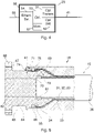
- Figure 4 illustrates an example of interrogating equipment 20 connected to the fibre 41.
- An optical transmitter 51 generates an optical signal and transmits it into the fibre 41.
- light is reflected from each sensor 42 in the fibre 41 and then received and processed in an optical detector 52.
- Light reflected from the individual optical fibre sensors 42 can be distinguished e.g. by using light wavelength shift for each sensor or by sensing the time delay as a light pulse passes along the fibre 41 through each sensor.
- a controller 53 controls the optical transmitter 51 to transmit light, i.e.
- the interrogation equipment 20 in an example not according to the invention comprise an Ethernet switch 54 connected to a cable 55, which may be a twisted pair or a fiber optic link.
- the signals representing determined parameters or received light values may be transmitted to the instrumentation room according to other protocol types or as analog electrical or optical signals.
- the interrogation equipment is configured to transmit the signals wirelessly to the instrumentation room.
- the data can be stored on a storage medium or memory 57 in the interrogation equipment 20 and subsequently retrieved manually at a certain frequency.
- the storage medium 57 can be any storage medium suitable for storing data. As examples can be mentioned memory cards, USB sticks, CD-ROMs, DVDs or a hard disk.
- the optical fibre sensors 42 are integrated in the fibre 41 itself as so-called intrinsic sensors.
- Different types of optical fibre sensors can be employed, but fibre Bragg gratings are particularly advantageous for this use, because fibre optic sensors using fibre Bragg gratings can measure co-located temperature and strain simultaneously with high accuracy.
- a fibre Bragg grating is a distributed Bragg reflector constructed in a short segment of the optical fibre that reflects particular wavelengths of light and transmits all others. This is achieved by a periodic variation in the refractive index of the fibre core, which provides a wavelength-specific dielectric mirror. The Bragg wavelength is sensitive to strain as well as to temperature.
- fibre Bragg gratings can be used as sensing elements for one of these parameters in optical fibre sensors, because the parameters cause a shift in the Bragg wavelength, which can then be detected in the optical detector 52.
- the fibre may also just be used as a means of relaying signals from remote non-fibre optical sensors to the interrogating equipment, which is referred to as extrinsic sensors.
- the unbonded flexible pipe 15 is connected to or received by the turret 4 by means of an end-fitting 16.
- the turret 4 further comprises a pipe 17 connected to the end-fitting 16 by means of a flange 18, so that the flow of liquids and/or gases arriving on board the FPSO 1 from e.g. subsea oil wells via the unbonded flexible pipe 15 continues through the pipe 17.
- a platform 19 on which the interrogating equipment 20 can be arranged is attached to the pipe 17.
- the interrogating equipment 20 can be arranged directly at the top side of the turret 4 itself next to the flange 18.
- the environment in the turret compartment can be quite tough, and therefore, the interrogating equipment 20 is arranged in an enclosure 56 that is certified according to ATEX Zone 1, i.e. a place in which an explosive atmosphere consisting of a mixture with air of dangerous substances in the form of gas, vapor or mist is likely to occur in normal operation occasionally.
- the enclosure 56 is further rated to IP68, and it is designed with an ambient temperature rating of -40°C to +60°C.
- the end-fitting 16 can be provided with a fibre exit cavity with means for connecting the fibre 41 via the end-fitting 16 to the interrogating equipment or to another waveguide leading to the interrogating equipment.
- Figure 5 illustrates a schematic cross-sectional side view of an example of an assembly of the flexible pipe 15 and the end-fitting 16, wherein the optical fibre has an overlength in the fibre exit cavity of the end-fitting.
- the unbonded flexible pipe 15 comprises an outer sealing sheath 36 surrounding two cross-wound tensile armour layers 34 and 35.
- the pipe comprises a number of other layers, including e.g. the carcass 31, the inner sealing sheath 32 and the pressure armour layer 33.
- the layers 31, 32 and 33 inside the cross-wound tensile armour layers 34 and 35 will usually be terminated individually, as shown schematically in the drawing with the terminating unit 61.
- the end-fitting 16 comprises an annular end-fitting body structure 62 and an annular outer casing 63.
- the end-fitting body structure 62 comprises an end-fitting body 64 with a narrow section 65, a housing cavity 66, and a mounting flange 67 with holes 68 for mounting to another part, e.g. the turret 4.
- the housing cavity 66 is formed between the end-fitting body 64 and the outer casing 63.
- the outer sealing sheath 36 is terminated at a termination point 69 in well known manner.
- the tensile armour elements of the tensile armour layers 34 and 35 are terminated and secured by securing material in the housing cavity 66 of the end-fitting 16.
- the end-fitting 16 further comprises a fibre exit cavity 71 with an entrance end 72 and an exit opening 73 through which the fibre 41 can exit.
- the fibre is applied in an overlength in the fibre exit cavity 71, which means that the optical fibre section in the exit cavity 71 is longer than the length from the entrance end 72 to the exit opening 73 of the exit cavity.
- the end-fitting 16 comprises a lid 74 covering the exit opening 73.
- the optical fibre 41 is terminated in the exit cavity 71 in that it is at least temporally fixed to the lid 74.
- the end-fitting 16 comprises a fibre guide unit 75 arranged in the housing cavity 66 and the optical fibre 41 is passing through said fibre guide unit 75.
- the fibre may be terminated within the exit cavity 71 and mounted with a connector for fast and simple mounting to e.g. the interrogating equipment 20 or a waveguide leading to the interrogating equipment 20.
- a lid may then cover the exit cavity 71 at its exit opening 73 to protect the fibre against dust and dirt and simultaneously ensuring a mechanical protection. In use, the lid can be removed and the fibre connector can be withdrawn for connection to the interrogating equipment 20.
- an optical fibre 21, or another type of optical waveguide connects the optical fibre 41 to the interrogating equipment 20, but as mentioned, the overlength of the fibre 41 in the exit cavity 71 may also be sufficiently long for connecting the fibre 41 directly to the interrogating equipment 20. Since the interrogating equipment 20 is placed on the geostationary turret 4, a connection of sufficient quality between the optical fibre 41 and the interrogating equipment 20 is ensured, even when the FPSO 1 rotates around the turret 4 according to changing weather conditions.
- a swivel device 22 joins the pipe 17 on the geostationary turret 4 with another pipe 23, which is a part of the FPSO 1 and thus able to turn with respect to the geostationary turret 4.
- the pipe 23 leads to processing equipment and/or storage on the FPSO.
- the swivel device 22 provides a fluid transfer path between the turret 4 and the free weathervaning FPSO 1 when the FPSO rotates around the turret.
- the swivel device 22 can transmit electrical signals between the turret 4 and the FPSO 1.
- an electrical output signal from the interrogation equipment 20 can be transmitted via the electrical connection 25, the slip ring 24 and the electrical connection 26 to a local instrumentation room 27 placed on board the FPSO 1.
- This connection can of course also be used to control the interrogating equipment 20 from the local instrumentation room 27.
- this connection may typically be an Ethernet connection.
- the slip ring 24 may also allow optical signals to be transferred between the turret and the FPSO, typically by using a fibre optic rotary joint having a plurality of optical transmitters and/or a plurality of optical receivers arranged on a rotor and a stator, respectively.
- a rise and fall of the received optical signal strength during rotation is inherent in combination with a large insertion loss and a large variation in loss and polarisation. This means that although a swivel device using a fibre optic rotary joint may provide an acceptable performance for the transmission of digitized optical signals, e.g.
- Ethernet signals the performance for transmission of analog optical signals through the swivel device is very poor because the signals are distorted by the fibre optic rotary joint.
- the optical signals reflected from the sensing fibre 41 integrated in the unbonded flexible pipe 15 cannot be passed through a swivel device without being distorted to a degree that prevents the sensor system from detecting changes in strain and/or temperature in the unbonded flexible pipe 15. This problem is avoided by placing the interrogating equipment 20 on the geostationary turret 4.
- an unbonded flexible pipe 15 with a single optical fibre 41 integrated in a helically wound armouring element of one of the armouring layers was shown.
- an unbonded flexible pipe may be provided with several optical fibres integrated in corresponding armouring elements.
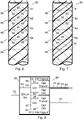
- Figure 6 shows an unbonded flexible pipe 80 having four optical fibres 81, 82, 83 and 84 integrated in the armouring elements.
- a plurality of optical fibre sensors 85 are arranged to measure or detect changes in e.g. strain or temperature of the armouring element on their respective locations.
- the optical fibre sensors 85 of each fibre are arranged with equal distances between them, and in this embodiment, sensors 85 belonging to different optical fibres are arranged so that measurements can be performed at coinciding cross sections 86 of the unbonded flexible pipe 80.
- the optical transmitter 51 and the optical receiver 52 of the interrogating equipment 20 may be multiplexed between the fibres, or the interrogating equipment 20 may have separate transmitters and receivers for each fibre.
- distributed temperature sensing along an optical fibre which uses Raman-shifted backscatter from laser pulses to determine the temperature along the optical fibre, may also be used.
- Distributed temperature sensing systems measure temperatures by means of the optical fibre functioning as a linear sensor. Temperatures are recorded along the optical fibre, i.e. not at points, but as a continuous profile.
- Distributed temperature sensing is based on the fact that physical measurement dimensions, such as temperature or pressure and tensile forces, can affect a glass fibre and locally change the characteristics of light transmission in the fibre.
- physical measurement dimensions such as temperature or pressure and tensile forces
- Raman scattering occurring in the optical fibre
- the location of an external physical effect can be determined so that the optical fibre can be employed as a linear sensor.
- the optical fibre is passive in nature and has no individual sensing points.
- Figure 7 shows an unbonded flexible pipe 90 having a further fibre 91 in addition to the four fibres 81, 82, 83 and 84 of Figure 6 .
- the fibre 91 is integrated in a helically wound armouring element of one of the armouring layers, but in contrast to the fibres 81, 82, 83 and 84, the fibre 91 does not have any optical fibre sensors arranged along the length of the fibre. Instead, the fibre 91 is used for distributed temperature sensing as described above.
- FIG 8 shows an example of an interrogating equipment 92 for use with the unbonded flexible pipe 90 having fibres 81, 82, 83 and 84 with optical fibre sensors arranged along the length of the fibre as well as a fibre 91 used for distributed temperature sensing.
- the interrogating equipment 92 comprises a strain interrogator 93 for detecting variations in strain via the fibres 81, 82, 83 and 84 and a distributed temperature sensing (DTS) interrogator 94 for detecting variations in temperature via the fibre 91.
- DTS distributed temperature sensing
- the strain interrogator 93 comprises an optical transmitter 51, an optical detector 52 and a controller 53 to control the optical transmitter 51 to transmit light and the optical receiver 52 to receive light reflected from the optical fibre sensors 85 of the fibres 81, 82, 83 and 84.
- the DTS interrogator 94 comprises an optical transmitter 95 for generating laser pulses and emitting them into the fibre 91 and an optical detector 96 for receiving optical signals reflected from the fibre 91. From a delay profile of the reflected signals the optical detector 96 can determine temperature variations along the fibre 91 and thus along the unbonded flexible pipe 90.
- a controller 97 controls the functions of the optical transmitter 95 and the optical detector 96.
- the fibres 81, 82, 83, 84 and 91 are shown as being directly connected to the interrogation equipment 92, which means that each one of these fibres has an overlength in an exit cavity of the end fitting 16 that is sufficiently long for connecting the fibre directly to the interrogating equipment 92.
- a separate optical fibre, or another type of optical waveguide may connect each of the fibres 81, 82, 83, 84 and 91 to the interrogating equipment 20 by using optical connectors in the exit cavities of the end fitting 16.
- the line representing the fibre 21 in Figure 1 represents the five fibres connected to the fibres 81, 82, 83, 84 and 91, respectively, in the exit cavities of the end fitting 16.
- the interrogation equipment 92 also comprises an Ethernet switch 54 connected to a cable 55, which may be a twisted pair or a fiber optic link.
- the Ethernet switch 54 is also connected to the controllers 53 and 97 so that the instrumentation room can receive information from and send instructions to the strain interrogator 93 as well as the DTS interrogator 94.
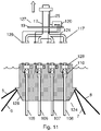
- each unbonded flexible pipe 105, 106, 107 and 108 is connected to or received by the turret 104 by means of an end-fitting 116.
- a pipe 117 is connected to each end-fitting 116, so that the flow of liquids and/or gases arriving on board the FPSO 1 from e.g. subsea oil wells via the unbonded flexible pipes 105, 106, 107 and 108 continues through the corresponding pipes 117.
- the four pipes 117 are combined to the main pipe 17, so that the flow of liquids and/or gases from all four unbonded flexible pipes 105, 106, 107 and 108 can be transferred through the pipe 17, the swivel device 22 and the pipe 23 to processing equipment and/or storage on the FPSO.
- each optical fibre of one of the unbonded flexible pipes 105, 106, 107 and 108 is connected to the interrogating equipment 120 by an optical connection 121, e.g. an optical fibre or another type of optical waveguide, or the overlength of the fibre in the exit cavity 71 of the corresponding end fitting 116 may be sufficiently long for connecting the fibre directly to the interrogating equipment 120.
- the optical connection 121 can be a single optical fibre, while it can consist of five optical fibres connected to the fibres 81, 82, 83, 84 and 91, respectively, if unbonded flexible pipe 90 having five integrated fibres as shown in Figure 7 is used.
- the interrogating equipment 120 may comprise interrogators for each one of the four unbonded flexible pipes 105, 106, 107 and 108, or separate interrogating equipment may be used for each unbonded flexible pipe.
- a turret may be separated into two parts, which is illustrated with the turret 124 in Figure 10 , which can be separated along the disconnection plane 125 into a lower part 126 for receiving the unbonded flexible pipes 105, 106, 107 and 108 in the end fittings 116 and an upper part 127 comprising the pipes 17 and 117 and the platform 19 for the interrogating equipment 120.
- This allows the FPSO to release the lower part 126 of the turret and move to another position, e.g. in case of an emergency situation, such as a cyclone or an iceberg, or just to be connected to another turret at the other position.
- the lower part 126 of the turret will then sink beneath the waves and can be reconnected later.
- each unbonded flexible pipe 105, 106, 107 and 108 is provided with a valve 128 that allows the flow of liquids and/or gases from that pipe to be cut off before disconnection.
- each optical fibre 121 connecting the end fitting 116 to the interrogating equipment 120 is arranged to be disconnected by dividing the fibre into two sections that can be connected to each other by means of optical connectors129. Since the connector parts of the optical connector 129 can be left below the water when disconnected, so-called subsea wet-mate connectors must be used.
- valves 128 are closed and the upper part 127 and the lower part 126 are then separated from each other as illustrated in Figure 11 . Normally, the upper part 127 will remain in the FPSO 1.
- the invention is described in relation to a so-called internal turret, where the turret is located in the hull of a vessel, i.e. in this case the FPSO 1.
- the turret is located in the front end of the FPSO, but in some cases, the turret can be found in the middle of the ship.
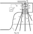
- the invention can also be used in combination with an external turret, where the turret is located outside the hull of the ship, e.g. at the bow or stern of the vessel.
- the FPSO 131 in Figure 12 An example of this is shown as the FPSO 131 in Figure 12 .
- the hull 132 of the FPSO 131 is provided with a projection 135, e.g. at the bow of the FPSO 131.
- This projection 135 has a substantially vertical shaft, chamber or compartment 133 for receiving and supporting the turret 134.
- the turret 134 is moored to the seabed by chains or wires 5, 6, 7 and 8 ensuring that the turret can maintain a geostatic position, and a riser in the form of an unbonded flexible pipe 15 coming from the seabed is connected to the turret 134 by means of an end-fitting 16.
- the upper part of the turret 134 comprises a pipe 17 connected to the end-fitting 16, so that the flow of liquids and/or gases arriving on board the FPSO 131 from e.g. subsea oil wells via the unbonded flexible pipe 15 continues through the pipe 17.
- a platform 19 on which the interrogating equipment 20 can be arranged is attached to the pipe 17.
- the interrogating equipment 20 can be arranged directly at the top side of the turret 134 itself.
- An optical fibre 21, or another type of optical waveguide connects the optical fibre of the unbonded flexible pipe 15 to the interrogating equipment 20, but as mentioned earlier, the overlength of the fibre 41 in the exit cavity 71 of the end-fitting 16 may also be sufficiently long for connecting the fibre 41 directly to the interrogating equipment 20. Since the interrogating equipment 20 is placed on the geostationary turret 134, a connection of sufficient quality between the optical fibre 41 and the interrogating equipment 20 is ensured, even when the FPSO 131 rotates around the turret 134 according to changing weather conditions.
- a swivel device 22 joins the pipe 17 on the geostationary turret 4 with another pipe 23, which is a part of the FPSO 131 and thus able to turn with respect to the geostationary turret 134.
- the pipe 23 leads to processing equipment and/or storage on the FPSO.
- the swivel device 22 provides a fluid transfer path between the turret 134 and the free weathervaning FPSO 131 when the FPSO rotates around the turret.
- the swivel device 22 can transmit electrical signals between the turret 134 and the FPSO 131.
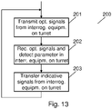
- Figure 13 shows a flow chart 200 illustrating a method of detecting a parameter, such as a temperature or strain value, in an unbonded flexible pipe having one or more optical fibres integrated in an armouring layer, where the unbonded flexible pipe is connected rotationally to a floating vessel via a turret and a swivel device as described above.
- step 201 optical signals are transmitted into the one or more optical fibres from an optical transmitter in interrogating equipment that is arranged on the turret, so that the optical fibre can be connected to the interrogating equipment without having to pass through a swivel device.
- step 202 optical signals reflected from the optical fibre in response to the optical signals transmitted into the fibre in step 201 are received in an optical detector in the interrogating equipment that is arranged on the turret, and the parameter of the unbonded flexible pipe is detected from the optical signals received from the fibre.
- step 203 signals indicative of the detected parameter is transferred to receiving equipment placed on the floating vessel from the interrogating equipment that is arranged on the turret. As described above, this can be done by wireless transmission.
Description
- The invention relates to a flexible pipe system comprising an unbonded flexible pipe with at least one optical fibre integrated in an armouring layer, where the unbonded flexible pipe is connected rotationally to a floating vessel via a turret and a swivel device. The invention also relates to a method of detecting at least one parameter in an unbonded flexible pipe having at least one armouring layer.
- Unbonded flexible pipes are well known in the art, in particular for offshore transportation of fluids or gases. They can be used e.g. for the transportation of fluids where very high or varying water pressures exist along the longitudinal axis of the pipe. This is the case e.g. for so-called riser pipes extending partly or totally from the seabed up to an installation on or near the surface of the sea, e.g. in the form of a floating vessel or a platform, or for pipes for transportation of liquid and gases between installations, pipes which are located at great depths on the seabed, or pipes between installations near the surface of the sea.
- Such pipes usually comprise a number of concentric layers, including an inner liner, often also referred to as an inner sealing sheath or an inner sheath, which forms a barrier against the outflow of the fluid that is conveyed through the pipe, and one or more armouring layers on the outer side of the inner liner. Typically, at least one of the armouring layers comprises a plurality of helically wound elongated armouring elements arranged around the internal sealing sheath. An outer sheath may be provided to provide a mechanical protection and/or for forming a barrier against the ingress of fluids from the pipe surroundings to the armouring layers.
- In this context, the term "unbonded" refers to the fact that at least two of the layers including the armouring layers and sheath layers are not bonded to each other. In practice, an unbonded flexible pipe normally comprises at least two armouring layers located outside the inner sealing sheath, where the armouring layers are not bonded to each other or to other layers directly or indirectly via other layers along the pipe. The pipe layers can therefore move relative to each other, and thereby the pipe becomes highly bendable, usable for dynamic applications, e.g. as risers, and sufficiently flexible to roll up for transportation even when the layers are relatively thick. This is necessary for high strength pipes, which should be able to withstand high pressure differences over layers of the pipe, e.g. pressure differences between the pressure inside the bore of the pipe and the pressure on the outer side of the pipe.
- Unbonded flexible pipes can be very long, and since the production of oil is performed at increasing water depths, the length as well as the requirement to strength of the unbonded flexible pipe is increased as well. A main reason for the increased requirements is that the greater the depth at which a flexible pipe is to be used, the higher the requirements will be to strength against collapsing due to external pressure. Furthermore, the weight of the pipe during deployment and use may result in high tensile forces, which increase with the length of the pipe and the depth at the deployment site. The higher the strength that needs to be provided, the more critical the integrity of individual tensile armouring elements becomes.
- Therefore, armouring layers need to be monitored for potential breaks in the armouring elements, which could occur during use, even normal use, of the pipe due to the stress that the unbonded flexible pipe is subjected to during its use, in particular when used as a riser.
- One way of detecting a break of an elongated armouring element of an unbonded flexible pipe is to use a flexible pipe system, in which the unbonded flexible pipe has a sensor system based on the use of one or more optical fibres at least partly integrated in at least one armouring layer of the unbonded flexible pipe.
- Typically, the sensor system comprises interrogating equipment placed on the sea surface installation and a plurality of optical fibre sensors integrated in one or more of the elongated armouring elements of an armouring layer. Each one of these armouring elements has integrated therein at least one optical fibre comprising a plurality of optical fibre sensors. The optical fibre sensors extend along a monitoring length section of the flexible pipe, and they are arranged to measure or determine a change in strain of the respective armouring elements by transmitting a light signal from an optical transmitter in the interrogating equipment into the optical fibre and measuring in an optical detector light that is reflected from the fibre to the interrogating equipment. In the optical detector, or a computing unit to which it is connected, the reflected optical signals are processed for determining changes in e.g. intensity, phase, polarization, wavelength, or transit time of light in the fibre, which indicate a change in the strain and/or temperature along the fibre or at one of the sensors.
- In this way, the flexible pipe system can detect changes in strain that the elongated armouring elements experience, e.g. due to movements from waves etc., change in internal pressure, change in buoyancy of the pipe, or other influences. A special case of sudden change in strain is the breaking of an elongated armouring element. Such a failure reduces the residual strength of the flexible pipe and may ultimately result in catastrophic damage to the pipe. Therefore, in general a flexible pipe should be replaced after an elongated armouring element has broken, since this could indicate that other armouring elements may be at risk of breaking soon.
- Typically, several sensors are multiplexed along the length of the optical fibre, e.g. by using light wavelength shift for each sensor or by sensing the time delay as a light pulse passes along the fibre through each sensor. In addition to determining a change in strain, optical fibres can also be used as sensors to measure temperature, pressure and other quantities by modifying a fibre so that the quantity to be measured modulates e.g. the intensity, phase, polarization, wavelength, or transit time of light in the fibre.
- In principle, any type of optical fibre strain sensors could be employed, but fibre Bragg gratings are particularly advantageous for this use, because fibre optic sensors using fibre Bragg gratings can measure co-located temperature and strain simultaneously with high accuracy. As an alternative to a plurality of optical fibre sensors arranged along a fibre integrated in one of the elongated armouring elements of an armouring layer, distributed temperature sensing along an optical fibre, which uses Raman-shifted backscatter from laser pulses to determine the temperature along the optical fibre, may also be used. Distributed temperature sensing systems measure temperatures by means of the optical fibre functioning as a linear sensor. Temperatures are recorded along the optical fibre, i.e. not at points, but as a continuous profile.
-
WO2015/063457 discloses a pipeline apparatus comprising a flexible pipe body and a detection apparatus. The flexible pipe body includes an optical fibre extending at least partially along the length of the flexible pipe body, the optical fibre being encased in a metal tube. The detection apparatus comprises an optical sensor and an electrical sensor. The optical sensor is coupled to a first end of the optical fibre, the optical sensor being arranged to inject optical pulses into the optical fibre and to detect scattered or reflected light. The electrical sensor is coupled to a first end of the metal tube and to detect variation of an electrical impedance between the first end of the metal tube and a separate terminal. Variation of the scattered or reflected light, or impedance variation, is indicative of a potential pipe body defect. - By large water depths and/or in remote areas of the sea, the floating vessel with the sea surface installation for the risers using unbonded flexible pipes may typically be a floating production, storage and offloading (FPSO) unit, which is a floating facility or ship to which the risers coming from the seabed are connected. The FPSO is equipped with processing equipment for separation and treatment of the fluid arriving on board from subsea installation via the risers. Due to the size of an FPSO, the vessel need to be able to rotate freely in horizontal direction according to the directions of winds, waves and sea currents, while the risers remain connected to a fixed part on the seabed, and material is still allowed to pass through. The free rotation of the FPSO according to weather conditions is also referred to as weathervaning. The FPSO will normally lay head to the prevailing environment.
- To allow the free rotation, an FPSO is equipped with a turret mooring system, which is usually fitted inside and integrated into a substantially vertical shaft, chamber or compartment in the hull of the FPSO. A turret, which is typically cylindrical, is moored to the seabed with chains, wires and/or anchors, and bearings allow free and unrestricted 360° rotation of the FPSO around the turret, which is thus the geostatic part of the turret mooring system. The risers are connected to the geostatic turret, and a fluid transfer path between the turret and the free weathervaning FPSO rotating around the turret is provided by a swivel device. The turret system is fully passive and does not require active vessel heading control or active rotation systems in the turret or the swivel device.
- The swivel device may also be arranged to transmit electrical signals between the turret and the free rotating FPSO. Some swivel devices also allow optical signals to be transferred between the turret and the FPSO, typically by using a fibre optic rotary joint having a plurality of optical transmitters and/or a plurality of optical receivers arranged on a rotor and a stator, respectively. In such a plural input/plural pickup system, a rise and fall of the received optical signal strength during rotation is inherent in combination with a large insertion loss and a large variation in loss and polarisation. This means that although swivel devices using fibre optic rotary joints may provide an acceptable performance for the transmission of digitized optical signals, the performance for transmission of analog optical signals through the swivel device is very poor because the signals are distorted by the fibre optic rotary joint.
- Thus, the optical signals reflected from a sensing fibre integrated in an unbonded flexible pipe to interrogating equipment placed on the FPSO cannot be passed through a swivel device without being distorted to a degree that prevents the sensor system from detecting changes in strain and/or temperature in the unbonded flexible pipe. This means that on floating vessels equipped with a turret mooring system to allow the free horizontal rotation of the vessel according to weather conditions, sensor systems based on optical fibres integrated in an armouring layer of an unbonded flexible pipe cannot be used with satisfactory results.
- Therefore, it is an object of embodiments of the invention to provide a flexible pipe system comprising a sensor system having an optical fibre integrated in an armouring layer of an unbonded flexible pipe, which can also be used for detecting changes in a parameter such as strain and/or temperature in the unbonded flexible pipe on floating vessels equipped with a turret mooring system.
- The invention is defined in the claims.
- The flexible pipe system comprises an unbonded flexible pipe comprising at least one armouring layer and connected to a floating vessel; a sensor system comprising at least one optical fibre integrated in the at least one armouring layer of the unbonded flexible pipe; and interrogating equipment having an optical transmitter configured to transmit optical signals into said at least one optical fibre; and an optical detector configured to receive optical signals reflected from said at least one optical fibre and to detect therefrom at least one parameter in said unbonded flexible pipe; a turret for rotationally connecting the unbonded flexible pipe to the floating vessel, said turret being supported by a substantially vertical shaft in the floating vessel and comprising an end-fitting for terminating and securing said unbonded flexible pipe to the turret; and a swivel device for rotationally connecting the turret to the shaft of the floating vessel and providing a fluid transfer passage between the turret and the floating vessel, wherein said interrogating equipment is arranged on said turret and is further configured to transfer signals indicative of said at least one detected parameter to receiving equipment on said floating vessel.
- When the interrogating equipment is arranged on the turret, it is achieved that the optical signals reflected from the fibre can reach the interrogating equipment without being distorted in a swivel device, so that parameters for the unbonded flexible pipe can be detected with a sufficient quality also in cases where a floating vessel is equipped with a turret mooring system. The possibility of transferring signals indicative of the parameter detected in the interrogating equipment to receiving equipment on the floating vessel ensures that the parameters of the unbonded flexible cable can still be monitored e.g. by monitoring equipment or personnel in a control room on board the floating vessel.
- In an embodiment, the interrogating equipment comprises a transmitter for transmitting said signals indicative of said at least one detected parameter to the receiving equipment on said floating vessel.
- The flexible pipe system is configured to transmit said signals through said swivel device.
- The transmitter for transmitting said indicative signals is configured to transmit the signals as wireless signals.
- Expediently, the receiving equipment may be arranged in a local instrumentation room on said floating vessel, where the detected parameters can be monitored by monitoring equipment or personnel on board the floating vessel.
- In an embodiment, said interrogating equipment is arranged in an enclosure that is certified according to
ATEX Zone 1 and rated to IP68. This protects the equipment against the quite tough environment in the turret compartment. - In an embodiment, the floating vessel is a floating production, storage and offloading unit, FPSO.
- The turret may be an internal turret located in the hull of said floating vessel. This embodiment is most useful in relatively harsh environments, among other things because the mooring forces can be transferred more easily into the hull of the floating vessel.
- Alternatively, the turret may be an external turret located in a projection extending from the hull of said floating vessel. This embodiment is mostly used in relatively calm waters, and it can easily be mounted e.g. on a tanker in order to convert the tanker to an FPSO.
- Expediently, the turret may have a cylindrical shape. This facilitates the rotation in the shaft of the floating vessel.
- In an embodiment, the turret is configured to be separated along a disconnection plane into a lower part for receiving the unbonded flexible pipe and an upper part comprising the interrogating equipment. This allows the floating vessel to release the lower part of the turret and move to another position, e.g. in case of an emergency situation, such as a cyclone or an iceberg, or just to be connected to another turret at the other position.
- In an embodiment, the turret is configured to connect a plurality of unbonded flexible pipes to the floating vessel. This increases the capacity of the vessel considerably.
- In an embodiment, a plurality of optical fibre sensors are arranged along said optical fibre. The plurality of optical fibre sensors may be intrinsic sensors integrated in said optical fibre, and each one of said intrinsic sensors may then comprise a fibre Bragg grating. Alternatively, the plurality of optical fibre sensors may be extrinsic sensors connected to said optical fibre.
- The sensor system may comprise a plurality of optical fibres integrated in corresponding armouring elements of an armouring layer of the unbonded flexible pipe, and each of said plurality of optical fibres may comprise a plurality of optical fibre sensors arranged with equal distances between them along the fibre, so that a plurality of optical fibre sensors are arranged at coinciding cross sections of the unbonded flexible pipe. This improves the accuracy of the measurements in the unbonded flexible pipe.
- In embodiments in which a plurality of optical fibre sensors are arranged along said optical fibre, the sensor system may comprise at least one further optical fibre integrated in an armouring element of an armouring layer of the unbonded flexible pipe, and said interrogating equipment may be configured to perform distributed temperature sensing by transmitting laser pulses into said further fibre and determining temperatures along said further fibre based on Raman-shifted backscatter from said laser pulses. This allows the fibre with a plurality of optical fibre sensors to be used for strain detection and the further fibre to be used for temperature detection.
- In other embodiments, the interrogating equipment may be configured to perform distributed temperature sensing by transmitting laser pulses into said optical fibre and determining temperatures along said optical fibre based on Raman-shifted backscatter from said laser pulses.
- As mentioned, the invention further relates to a method of detecting at least one parameter in an unbonded flexible pipe having at least one armouring layer in a flexible pipe system further comprising a turret for rotationally connecting the unbonded flexible pipe to a floating vessel, said turret being supported by a substantially vertical shaft in the floating vessel and comprising an end-fitting for terminating and securing said unbonded flexible pipe to the turret; a swivel device for rotationally connecting the turret to the shaft of the floating vessel and providing a fluid transfer passage between the turret and the floating vessel; and a sensor system comprising at least one optical fibre integrated in the at least one armouring layer of the unbonded flexible pipe, the method comprising the steps of transmitting optical signals into said at least one optical fibre from an optical transmitter of interrogating equipment arranged on said turret; receiving optical signals reflected from said at least one optical fibre and detecting therefrom at least one parameter in said unbonded flexible pipe in an optical detector of said interrogating equipment arranged on said turret; and transferring signals indicative of said at least one detected parameter to receiving equipment on said floating vessel from said interrogating equipment arranged on said turret.
- When the optical signals reflected from the optical fibre are received and at least one parameter in said unbonded flexible pipe is detected therefrom in an optical detector of interrogating equipment arranged on the turret, it is achieved that the optical signals reflected from the fibre can reach the interrogating equipment without being distorted in a swivel device, so that parameters for the unbonded flexible pipe can be detected with a sufficient quality also in cases where a floating vessel is equipped with a turret mooring system. Transferring signals indicative of the detected parameter to receiving equipment on the floating vessel from the interrogating equipment arranged on the turret ensures that the parameters of the unbonded flexible cable can still be monitored e.g. by monitoring equipment or personnel in a control room on board the floating vessel.
- The method further comprises the step of transmitting said signals indicative of said at least one detected parameter to the receiving equipment on said floating vessel from said interrogating equipment arranged on said turret.
- The indicative signals is transmitted as wireless signals, or the indicative signals may be stored on a storage medium in said interrogating equipment for subsequent manual retrieval.
- Embodiments of the invention will now be described more fully below with reference to the drawings, in which
-
Figure 1 shows a floating production, storage and offloading (FPSO) unit having a turret on which interrogating equipment is arranged for performing measurements on an optical fibre integrated in an unbonded flexible pipe connected to the turret; -
Figure 2 shows an example of an unbonded flexible pipe comprising a number of concentric layers; -
Figure 3 shows an example of an optical fibre with a plurality of optical fibre sensors integrated in a helically wound armouring element of an armouring layer in the unbonded flexible pipe ofFigure 2 ; -
Figure 4 shows an example of interrogating equipment for performing measurements on the fibre ofFigure 3 ; -
Figure 5 shows a schematic cross-sectional side view of an example of an end-fitting for terminating an unbonded flexible pipe in the turret ofFigure 1 ; -
Figure 6 shows an unbonded flexible pipe having four optical fibres with optical fibre sensors integrated in the armouring elements of an armouring layer; -
Figure 7 shows the unbonded flexible pipe ofFigure 6 having a further fibre integrated in a helically wound armouring element of one of the armouring layers, which is used for distributed temperature sensing; -
Figure 8 shows an example of interrogating equipment for performing measurements on the fibres of the unbonded flexible pipe ofFigure 7 ; -
Figure 9 shows a floating production, storage and offloading (FPSO) unit having a turret on which interrogating equipment is arranged for performing measurements on optical fibres integrated in four unbonded flexible pipes connected to the turret; -
Figure 10 shows a floating production, storage and offloading (FPSO) unit having a turret, which can be separated along a disconnection plane into a lower part for receiving the unbonded flexible pipes and an upper part comprising the interrogating equipment; -
Figure 11 shows the turret ofFigure 10 when the upper part and the lower part have been separated from each other; -
Figure 12 shows a floating production, storage and offloading (FPSO) unit having an external turret, where the turret on which interrogating equipment is arranged is located outside the hull of the ship; and -
Figure 13 shows a flow chart illustrating a method of detecting a parameter in an unbonded flexible pipe from interrogating equipment arranged on a turret on a floating production, storage and offloading (FPSO) unit. - As an example of a floating vessel, in which the invention can be used,
Figure 1 shows a floating production, storage and offloading (FPSO)unit 1 that can be used as a sea surface installation in the offshore oil and gas industry for separating, treating and storing liquids and/or gases arriving on board from e.g. subsea oil wells via unbonded flexible pipes acting as so-called risers. Thehull 2 of theFPSO 1 is provided with a substantially vertical shaft, chamber orcompartment 3, typically having a cylindrical form, for receiving and supporting aturret 4. The typicallycylindrical turret 4 is moored to the seabed by chains orwires turret 4 also hasbearings shaft 3 allowing theFPSO 1 to rotate 360° in a horizontal plane freely and unrestricted around thegeostatic turret 4 according to the directions of winds, waves and sea currents. The free rotation of theFPSO 1 according to weather conditions is also referred to as weathervaning. A riser in the form of an unbondedflexible pipe 15 coming from the seabed is connected to theturret 4 by means of an end-fitting 16. - An example of an unbonded
flexible pipe 15 comprising a number of concentric layers is illustrated inFigure 2 . Theflexible pipe 15 comprises a liquid imperviousinner sealing sheath 32 defining a bore as indicated with the bold arrow. Theinner sealing sheath 32, often also called an inner liner, can be made of a polymer material suitable for forming such liquid impervious barrier. Theinner sealing sheath 32 has the purpose of preventing outflow of the fluid transferred in the bore of the pipe, indicated with the bold arrow. - Inside the
inner sealing sheath 32, the unbonded flexible pipe comprises aninner armour layer 31 called a carcass, which is normally of metal and has the main purpose of reinforcing the unbonded flexible pipe against collapse. - On the outer side of the
inner sealing sheath 32, the unbonded flexible pipe comprises three outer armouring layers 33, 34 and 35. Theouter armouring layer 33 closest to theinner sealing sheath 32 is apressure armour layer 33, which is often made of helically wound armour elements of metal or composite material, which is wound with a short pitch, i.e. with a steep angle to the centre axis of the unbonded flexible pipe, e.g. close to 90 degrees. Thepressure armour layer 33 is not liquid tight. - Around the
pressure armour layer 33, the unbonded flexible pipe comprises two cross-wound tensile armour layers 34, 35 wound from elongate armour elements, e.g. profiles and/or strips made of composite material and/or metal. For example, the elongate armouring elements on the innermosttensile armour layer 34 are wound with a winding degree of about 55 degrees or less to the axis of the unbonded flexible pipe in a first winding direction, while the outermosttensile armour layer 35 is wound with a winding degree of about 60 degrees or less to the axis of the unbonded flexible pipe in a second winding direction, which is the opposite direction to the first winding direction. The two armour layers with such opposite winding direction are normally referred to as being cross-wound. - The unbonded flexible pipe further comprises a liquid impervious
outer sealing sheath 36, which protects the armour layers mechanically and against ingress of sea water. - This type of flexible pipe is called unbonded because at least two of the layers including the armouring layers and sheath layers are not bonded to each other. In practice, the armouring layers are not bonded to each other or to other layers directly or indirectly via other layers along the pipe. The pipe layers can therefore move relative to each other, and thereby the pipe becomes highly bendable, usable for dynamic applications e.g. as risers, and sufficiently flexible to roll up for transportation even when the layers are relatively thick.
- In order to be able to monitor armouring layers, e.g. one of the
layers flexible pipe 15 for potential breaks in the helically wound armouring elements, which could occur during use of the pipe due to the stress that the unbonded flexible pipe is subjected to during its use, the unbonded flexible pipe may be provided with one or more optical fibres at least partly integrated in one or more armouring elements of at least one armouring layer of the unbonded flexible pipe. -
Figure 3 shows an example of anoptical fibre 41 integrated in an unbondedflexible pipe 15. Since thefibre 41 is integrated in a helically wound armouring element of one of the armouring layers 33, 34 and 35, the pitch of thefibre 41, i.e. the angle to the centre axis of the unbonded flexible pipe, corresponds to that of the armouring element. Along thefibre 41, a plurality ofoptical fibre sensors 42 are arranged to measure or detect changes in e.g. strain or temperature of the armouring element on their respective locations. Theoptical fibre sensors 42 are arranged with equal distances between them so that measurements can be performed at correspondingcross sections 43 of the unbondedflexible pipe 15. - The measurement or detection of changes in strain or temperature along the
fibre 41 is performed by transmitting a light signal into one end of the fibre and detecting light that is reflected from the fibre. To this purpose, interrogating equipment is used.Figure 4 illustrates an example of interrogatingequipment 20 connected to thefibre 41. Anoptical transmitter 51 generates an optical signal and transmits it into thefibre 41. As described in further detail below, light is reflected from eachsensor 42 in thefibre 41 and then received and processed in anoptical detector 52. Light reflected from the individualoptical fibre sensors 42 can be distinguished e.g. by using light wavelength shift for each sensor or by sensing the time delay as a light pulse passes along thefibre 41 through each sensor. Acontroller 53 controls theoptical transmitter 51 to transmit light, i.e. light pulses or continuous light and the wavelength of the light, and theoptical receiver 52 to receive the reflected light, e.g. at the right times and at the right wavelengths. Thecontroller 53 may also analyse the reflected light in order to determine the parameters to be measured, such as temperature and strain along the unbonded flexible pipe, or it may just convert the received light values to a more robust signal type and transmit them to further computation elsewhere on theFPSO 1, e.g. in a local instrumentation room. To be able to transmit signals representing determined parameters or received light values to such other location, theinterrogation equipment 20 in an example not according to the invention comprise anEthernet switch 54 connected to acable 55, which may be a twisted pair or a fiber optic link. In other examples, the signals representing determined parameters or received light values may be transmitted to the instrumentation room according to other protocol types or as analog electrical or optical signals. In accordance with the invention, the the interrogation equipment is configured to transmit the signals wirelessly to the instrumentation room. Alternatively - not according to the invention, the data can be stored on a storage medium ormemory 57 in theinterrogation equipment 20 and subsequently retrieved manually at a certain frequency. Thestorage medium 57 can be any storage medium suitable for storing data. As examples can be mentioned memory cards, USB sticks, CD-ROMs, DVDs or a hard disk. - Normally, the
optical fibre sensors 42 are integrated in thefibre 41 itself as so-called intrinsic sensors. Different types of optical fibre sensors can be employed, but fibre Bragg gratings are particularly advantageous for this use, because fibre optic sensors using fibre Bragg gratings can measure co-located temperature and strain simultaneously with high accuracy. A fibre Bragg grating is a distributed Bragg reflector constructed in a short segment of the optical fibre that reflects particular wavelengths of light and transmits all others. This is achieved by a periodic variation in the refractive index of the fibre core, which provides a wavelength-specific dielectric mirror. The Bragg wavelength is sensitive to strain as well as to temperature. Thus, fibre Bragg gratings can be used as sensing elements for one of these parameters in optical fibre sensors, because the parameters cause a shift in the Bragg wavelength, which can then be detected in theoptical detector 52. - Instead of using intrinsic sensors integrated in the
fibre 41 itself, the fibre may also just be used as a means of relaying signals from remote non-fibre optical sensors to the interrogating equipment, which is referred to as extrinsic sensors. - As shown in
Figure 1 , the unbondedflexible pipe 15 is connected to or received by theturret 4 by means of an end-fitting 16. In this embodiment, theturret 4 further comprises apipe 17 connected to the end-fitting 16 by means of aflange 18, so that the flow of liquids and/or gases arriving on board theFPSO 1 from e.g. subsea oil wells via the unbondedflexible pipe 15 continues through thepipe 17. Aplatform 19 on which the interrogatingequipment 20 can be arranged is attached to thepipe 17. Alternatively, the interrogatingequipment 20 can be arranged directly at the top side of theturret 4 itself next to theflange 18. - The environment in the turret compartment can be quite tough, and therefore, the interrogating
equipment 20 is arranged in anenclosure 56 that is certified according toATEX Zone 1, i.e. a place in which an explosive atmosphere consisting of a mixture with air of dangerous substances in the form of gas, vapor or mist is likely to occur in normal operation occasionally. Theenclosure 56 is further rated to IP68, and it is designed with an ambient temperature rating of -40°C to +60°C. - To connect the
fibre 41 to the interrogating equipment at the end of the unbondedflexible pipe 15, the end-fitting 16 can be provided with a fibre exit cavity with means for connecting thefibre 41 via the end-fitting 16 to the interrogating equipment or to another waveguide leading to the interrogating equipment. -
Figure 5 illustrates a schematic cross-sectional side view of an example of an assembly of theflexible pipe 15 and the end-fitting 16, wherein the optical fibre has an overlength in the fibre exit cavity of the end-fitting. As inFigure 2 , the unbondedflexible pipe 15 comprises anouter sealing sheath 36 surrounding two cross-wound tensile armour layers 34 and 35. Inside the cross-wound tensile armour layers 34 and 35, the pipe comprises a number of other layers, including e.g. thecarcass 31, theinner sealing sheath 32 and thepressure armour layer 33. Thelayers unit 61. - The end-fitting 16 comprises an annular end-fitting
body structure 62 and an annularouter casing 63. The end-fittingbody structure 62 comprises an end-fittingbody 64 with anarrow section 65, ahousing cavity 66, and a mountingflange 67 withholes 68 for mounting to another part, e.g. theturret 4. Thehousing cavity 66 is formed between the end-fittingbody 64 and theouter casing 63. Theouter sealing sheath 36 is terminated at atermination point 69 in well known manner. The tensile armour elements of the tensile armour layers 34 and 35 are terminated and secured by securing material in thehousing cavity 66 of the end-fitting 16. - The end-fitting 16 further comprises a
fibre exit cavity 71 with anentrance end 72 and anexit opening 73 through which thefibre 41 can exit. The fibre is applied in an overlength in thefibre exit cavity 71, which means that the optical fibre section in theexit cavity 71 is longer than the length from theentrance end 72 to the exit opening 73 of the exit cavity. - In this embodiment, the end-fitting 16 comprises a
lid 74 covering theexit opening 73. Theoptical fibre 41 is terminated in theexit cavity 71 in that it is at least temporally fixed to thelid 74. The end-fitting 16 comprises afibre guide unit 75 arranged in thehousing cavity 66 and theoptical fibre 41 is passing through saidfibre guide unit 75. Alternatively, the fibre may be terminated within theexit cavity 71 and mounted with a connector for fast and simple mounting to e.g. the interrogatingequipment 20 or a waveguide leading to the interrogatingequipment 20. A lid may then cover theexit cavity 71 at itsexit opening 73 to protect the fibre against dust and dirt and simultaneously ensuring a mechanical protection. In use, the lid can be removed and the fibre connector can be withdrawn for connection to the interrogatingequipment 20. - In
Figure 1 , anoptical fibre 21, or another type of optical waveguide, connects theoptical fibre 41 to the interrogatingequipment 20, but as mentioned, the overlength of thefibre 41 in theexit cavity 71 may also be sufficiently long for connecting thefibre 41 directly to the interrogatingequipment 20. Since the interrogatingequipment 20 is placed on thegeostationary turret 4, a connection of sufficient quality between theoptical fibre 41 and the interrogatingequipment 20 is ensured, even when theFPSO 1 rotates around theturret 4 according to changing weather conditions. - A
swivel device 22 joins thepipe 17 on thegeostationary turret 4 with anotherpipe 23, which is a part of theFPSO 1 and thus able to turn with respect to thegeostationary turret 4. Thepipe 23 leads to processing equipment and/or storage on the FPSO. In this way, theswivel device 22 provides a fluid transfer path between theturret 4 and thefree weathervaning FPSO 1 when the FPSO rotates around the turret. Through aslip ring 24, theswivel device 22 can transmit electrical signals between theturret 4 and theFPSO 1. In this case, an electrical output signal from theinterrogation equipment 20 can be transmitted via theelectrical connection 25, theslip ring 24 and theelectrical connection 26 to alocal instrumentation room 27 placed on board theFPSO 1. This connection can of course also be used to control the interrogatingequipment 20 from thelocal instrumentation room 27. As mentioned above, this connection may typically be an Ethernet connection. - It is noted that the
slip ring 24 may also allow optical signals to be transferred between the turret and the FPSO, typically by using a fibre optic rotary joint having a plurality of optical transmitters and/or a plurality of optical receivers arranged on a rotor and a stator, respectively. However, in such a plural input/plural pickup system, a rise and fall of the received optical signal strength during rotation is inherent in combination with a large insertion loss and a large variation in loss and polarisation. This means that although a swivel device using a fibre optic rotary joint may provide an acceptable performance for the transmission of digitized optical signals, e.g. Ethernet signals, the performance for transmission of analog optical signals through the swivel device is very poor because the signals are distorted by the fibre optic rotary joint. Thus, the optical signals reflected from thesensing fibre 41 integrated in the unbondedflexible pipe 15 cannot be passed through a swivel device without being distorted to a degree that prevents the sensor system from detecting changes in strain and/or temperature in the unbondedflexible pipe 15. This problem is avoided by placing the interrogatingequipment 20 on thegeostationary turret 4. - In
Figure 3 , an unbondedflexible pipe 15 with a singleoptical fibre 41 integrated in a helically wound armouring element of one of the armouring layers was shown. To improve the measurements of strain and/or temperature in the pipe, an unbonded flexible pipe may be provided with several optical fibres integrated in corresponding armouring elements. As an example,Figure 6 shows an unbondedflexible pipe 80 having fouroptical fibres - Along each fibre, a plurality of
optical fibre sensors 85 are arranged to measure or detect changes in e.g. strain or temperature of the armouring element on their respective locations. As inFigure 3 , theoptical fibre sensors 85 of each fibre are arranged with equal distances between them, and in this embodiment,sensors 85 belonging to different optical fibres are arranged so that measurements can be performed at coincidingcross sections 86 of the unbondedflexible pipe 80. To perform the measurements of strain and/or temperature along the fourfibres optical transmitter 51 and theoptical receiver 52 of the interrogatingequipment 20 may be multiplexed between the fibres, or the interrogatingequipment 20 may have separate transmitters and receivers for each fibre. - Instead of, or as a supplement to, using fibres having a plurality of optical fibre sensors arranged along the fibre integrated in one of the elongated armouring elements of an armouring layer as shown in
Figures 3 and6 , distributed temperature sensing along an optical fibre, which uses Raman-shifted backscatter from laser pulses to determine the temperature along the optical fibre, may also be used. Distributed temperature sensing systems measure temperatures by means of the optical fibre functioning as a linear sensor. Temperatures are recorded along the optical fibre, i.e. not at points, but as a continuous profile. - Distributed temperature sensing is based on the fact that physical measurement dimensions, such as temperature or pressure and tensile forces, can affect a glass fibre and locally change the characteristics of light transmission in the fibre. As a result of the damping of the light in the quartz glass fibre through light scattering, also known as Raman scattering, occurring in the optical fibre, the location of an external physical effect can be determined so that the optical fibre can be employed as a linear sensor. The optical fibre is passive in nature and has no individual sensing points.
- Thus,
Figure 7 shows an unbondedflexible pipe 90 having afurther fibre 91 in addition to the fourfibres Figure 6 . Like the fourfibres fibre 91 is integrated in a helically wound armouring element of one of the armouring layers, but in contrast to thefibres fibre 91 does not have any optical fibre sensors arranged along the length of the fibre. Instead, thefibre 91 is used for distributed temperature sensing as described above. -
Figure 8 shows an example of an interrogatingequipment 92 for use with the unbondedflexible pipe 90 havingfibres fibre 91 used for distributed temperature sensing. The interrogatingequipment 92 comprises a strain interrogator 93 for detecting variations in strain via thefibres interrogator 94 for detecting variations in temperature via thefibre 91. Similarly to the interrogatingequipment 20 ofFigure 4 , the strain interrogator 93 comprises anoptical transmitter 51, anoptical detector 52 and acontroller 53 to control theoptical transmitter 51 to transmit light and theoptical receiver 52 to receive light reflected from theoptical fibre sensors 85 of thefibres DTS interrogator 94 comprises anoptical transmitter 95 for generating laser pulses and emitting them into thefibre 91 and anoptical detector 96 for receiving optical signals reflected from thefibre 91. From a delay profile of the reflected signals theoptical detector 96 can determine temperature variations along thefibre 91 and thus along the unbondedflexible pipe 90. Acontroller 97 controls the functions of theoptical transmitter 95 and theoptical detector 96. - In
Figure 8 , thefibres interrogation equipment 92, which means that each one of these fibres has an overlength in an exit cavity of the end fitting 16 that is sufficiently long for connecting the fibre directly to the interrogatingequipment 92. Alternatively, a separate optical fibre, or another type of optical waveguide, may connect each of thefibres equipment 20 by using optical connectors in the exit cavities of the end fitting 16. It is also noted that in this situation, the line representing thefibre 21 inFigure 1 represents the five fibres connected to thefibres - To be able to transmit signals representing determined parameters or received light values to further computation elsewhere on the
FPSO 1, e.g. in a local instrumentation room, theinterrogation equipment 92 also comprises anEthernet switch 54 connected to acable 55, which may be a twisted pair or a fiber optic link. TheEthernet switch 54 is also connected to thecontrollers DTS interrogator 94. - In some embodiments, several risers in the form of unbonded flexible pipes coming from the seabed may be connected to the same turret. An example of this is shown in
Figure 9 , where theturret 104 receives four unbondedflexible pipes Figure 1 , each unbondedflexible pipe turret 104 by means of an end-fitting 116. Apipe 117 is connected to each end-fitting 116, so that the flow of liquids and/or gases arriving on board theFPSO 1 from e.g. subsea oil wells via the unbondedflexible pipes pipes 117. The fourpipes 117 are combined to themain pipe 17, so that the flow of liquids and/or gases from all four unbondedflexible pipes pipe 17, theswivel device 22 and thepipe 23 to processing equipment and/or storage on the FPSO. - As in
Figure 1 , each optical fibre of one of the unbondedflexible pipes equipment 120 by anoptical connection 121, e.g. an optical fibre or another type of optical waveguide, or the overlength of the fibre in theexit cavity 71 of the corresponding end fitting 116 may be sufficiently long for connecting the fibre directly to the interrogatingequipment 120. Thus, as examples, if an unbondedflexible pipe 15 having only one integratedfibre 41 as shown inFigure 3 is used, theoptical connection 121 can be a single optical fibre, while it can consist of five optical fibres connected to thefibres flexible pipe 90 having five integrated fibres as shown inFigure 7 is used. The interrogatingequipment 120 may comprise interrogators for each one of the four unbondedflexible pipes - In another embodiment, a turret may be separated into two parts, which is illustrated with the
turret 124 inFigure 10 , which can be separated along thedisconnection plane 125 into alower part 126 for receiving the unbondedflexible pipes end fittings 116 and anupper part 127 comprising thepipes platform 19 for the interrogatingequipment 120. This allows the FPSO to release thelower part 126 of the turret and move to another position, e.g. in case of an emergency situation, such as a cyclone or an iceberg, or just to be connected to another turret at the other position. Thelower part 126 of the turret will then sink beneath the waves and can be reconnected later. - To facilitate such disconnection, each unbonded
flexible pipe valve 128 that allows the flow of liquids and/or gases from that pipe to be cut off before disconnection. Also eachoptical fibre 121 connecting the end fitting 116 to the interrogatingequipment 120 is arranged to be disconnected by dividing the fibre into two sections that can be connected to each other by means of optical connectors129. Since the connector parts of theoptical connector 129 can be left below the water when disconnected, so-called subsea wet-mate connectors must be used. - In a situation where the
lower part 126 of theturret 124 should be separated from theFPSO 1, thevalves 128 are closed and theupper part 127 and thelower part 126 are then separated from each other as illustrated inFigure 11 . Normally, theupper part 127 will remain in theFPSO 1. - In the embodiments described above, the invention is described in relation to a so-called internal turret, where the turret is located in the hull of a vessel, i.e. in this case the
FPSO 1. Typically, the turret is located in the front end of the FPSO, but in some cases, the turret can be found in the middle of the ship. However, the invention can also be used in combination with an external turret, where the turret is located outside the hull of the ship, e.g. at the bow or stern of the vessel. - An example of this is shown as the FPSO 131 in
Figure 12 . The hull 132 of the FPSO 131 is provided with a projection 135, e.g. at the bow of the FPSO 131. This projection 135 has a substantially vertical shaft, chamber or compartment 133 for receiving and supporting the turret 134. Similarly to theturret 4 inFigure 1 , the turret 134 is moored to the seabed by chains orwires flexible pipe 15 coming from the seabed is connected to the turret 134 by means of an end-fitting 16. The upper part of the turret 134 comprises apipe 17 connected to the end-fitting 16, so that the flow of liquids and/or gases arriving on board the FPSO 131 from e.g. subsea oil wells via the unbondedflexible pipe 15 continues through thepipe 17. Aplatform 19 on which the interrogatingequipment 20 can be arranged is attached to thepipe 17. Alternatively, the interrogatingequipment 20 can be arranged directly at the top side of the turret 134 itself. - An
optical fibre 21, or another type of optical waveguide, connects the optical fibre of the unbondedflexible pipe 15 to the interrogatingequipment 20, but as mentioned earlier, the overlength of thefibre 41 in theexit cavity 71 of the end-fitting 16 may also be sufficiently long for connecting thefibre 41 directly to the interrogatingequipment 20. Since the interrogatingequipment 20 is placed on the geostationary turret 134, a connection of sufficient quality between theoptical fibre 41 and the interrogatingequipment 20 is ensured, even when the FPSO 131 rotates around the turret 134 according to changing weather conditions. - A
swivel device 22 joins thepipe 17 on thegeostationary turret 4 with anotherpipe 23, which is a part of the FPSO 131 and thus able to turn with respect to the geostationary turret 134. Thepipe 23 leads to processing equipment and/or storage on the FPSO. In this way, theswivel device 22 provides a fluid transfer path between the turret 134 and the free weathervaning FPSO 131 when the FPSO rotates around the turret. Through a slip ring, theswivel device 22 can transmit electrical signals between the turret 134 and the FPSO 131.Figure 13 shows aflow chart 200 illustrating a method of detecting a parameter, such as a temperature or strain value, in an unbonded flexible pipe having one or more optical fibres integrated in an armouring layer, where the unbonded flexible pipe is connected rotationally to a floating vessel via a turret and a swivel device as described above. Instep 201, optical signals are transmitted into the one or more optical fibres from an optical transmitter in interrogating equipment that is arranged on the turret, so that the optical fibre can be connected to the interrogating equipment without having to pass through a swivel device. Instep 202, optical signals reflected from the optical fibre in response to the optical signals transmitted into the fibre instep 201 are received in an optical detector in the interrogating equipment that is arranged on the turret, and the parameter of the unbonded flexible pipe is detected from the optical signals received from the fibre. Finally, instep 203, signals indicative of the detected parameter is transferred to receiving equipment placed on the floating vessel from the interrogating equipment that is arranged on the turret. As described above, this can be done by wireless transmission.
Claims (8)
- A flexible pipe system comprising:• an unbonded flexible pipe (15; 80; 90; 105, 106, 107, 108) comprising at least one armouring layer (31, 33, 34, 35) and being connected to a floating vessel (1; 131);• a sensor system adapted for detecting changes in strain and/or temperature in the unbonded flexible pipe and comprising:Characterized in that the flexible pipe system comprises∘ at least one optical fibre (41; 81, 82, 83, 84; 91) integrated in the at least one armouring layer (31, 33, 34, 35) of the unbonded flexible pipe (15; 80; 90; 105, 106, 107, 108); and∘ interrogating equipment (20; 92; 120) having an optical transmitter (51; 95) configured to transmit optical signals into said at least one optical fibre (41; 81, 82, 83, 84; 91); and an optical detector (52; 96) configured to receive optical signals reflected from said at least one optical fibre (41; 81, 82, 83, 84; 91) and to detect therefrom at least one parameter in said unbonded flexible pipe (15; 80; 90; 105, 106, 107, 108);• a turret (4; 104; 124; 134) for rotationally connecting the unbonded flexible pipe (15; 80; 90; 105, 106, 107, 108) to the floating vessel (1; 131), said turret (4; 104; 124; 134) being supported by a substantially vertical shaft (3; 133) in the floating vessel (1; 131) and comprising an end-fitting (16; 116) for terminating and securing said unbonded flexible pipe (15; 80; 90; 105, 106, 107, 108) to the turret (4; 104; 124; 134); and• a swivel device (22) for rotationally connecting the turret (4; 104; 124; 134) to the shaft (3; 133) of the floating vessel (1; 131) and providing a fluid transfer passage between the turret (4; 104; 124; 134) and the floating vessel (1; 131),
wherein said interrogating equipment (20; 92; 120) is located on said turret (4; 104; 124; 134) to provide that optical signals reflected from the fibre can reach the interrogating equipment without being distorted in the swivel device and is further configured to transfer signals indicative of said at least one detected parameter to receiving equipment (27) on said floating vessel (1; 131) and wherein said interrogating equipment (20; 92; 120) comprises a transmitter (54) for transmitting said signals indicative of said at least one detected parameter to the receiving equipment (27) on said floating vessel (1; 131), and wherein the flexible pipe system is configured to transmit said signals as wireless signals. - A flexible pipe system according to claim 1, wherein said interrogating equipment (20; 92; 120) is arranged in an enclosure (56) that is certified according to ATEX Zone 1 and rated to IP68.
- A flexible pipe system according to claim 1 or claim 2, wherein said turret is an internal turret (4; 104; 124) located in the hull (2) of said floating vessel (1).
- A flexible pipe system according to claim 1 or claim 2, wherein said turret is an external turret (134) located in a projection (135) extending from the hull (132) of said floating vessel (131).
- A flexible pipe system according to any one of claims 1 to 4, wherein a plurality of optical fibre sensors (42; 85) are arranged along said optical fibre (41; 81, 82, 83, 84), preferably said plurality of optical fibre sensors (42; 85) are intrinsic sensors integrated in said optical fibre (41; 81, 82, 83, 84) or said plurality of optical fibre sensors (42; 85) are extrinsic sensors connected to said optical fibre (41; 81, 82, 83, 84).
- A flexible pipe system according to claim 5, wherein• the sensor system comprises at least one further optical fibre (91) integrated in an armouring element of an armouring layer of the unbonded flexible pipe (90); and• said interrogating equipment (92) is configured to perform distributed temperature sensing by transmitting laser pulses into said further fibre (91) and determining temperatures along said further fibre (91) based on Raman-shifted backscatter from said laser pulses.
- A flexible pipe system according to any one of claims 1 to 4, wherein said interrogating equipment (92) is configured to perform distributed temperature sensing by transmitting laser pulses into said optical fibre (91) and determining temperatures along said optical fibre (91) based on Raman-shifted backscatter from said laser pulses.
- A method of detecting at least one parameter in an unbonded flexible pipe (15; 80; 90; 105, 106, 107, 108) having at least one armouring layer (31, 33, 34, 35) in a flexible pipe system further comprising:• a turret (4; 104; 124; 134) for rotationally connecting the unbonded flexible pipe (15; 80; 90; 105, 106, 107, 108) to a floating vessel (1; 131), said turret (4; 104; 124; 134) being supported by a substantially vertical shaft (3; 133) in the floating vessel (1; 131) and comprising an end-fitting (16; 116) for terminating and securing said unbonded flexible pipe (15; 80; 90; 105, 106, 107, 108) to the turret (4; 104; 124; 134);• a swivel device (22) for rotationally connecting the turret (4; 104; 124; 134) to the shaft (3; 133) of the floating vessel (1; 131) and providing a fluid transfer passage between the turret (4; 104; 124; 134) and the floating vessel (1; 131); and• a sensor system for detecting said at least one parameter and comprising at least one optical fibre (41; 81, 82, 83, 84; 91) integrated in the at least one armouring layer (31, 33, 34, 35) of the unbonded flexible pipe (15; 80; 90; 105, 106, 107, 108), wherein said at least one parameter being changes in strain and/or temperature in the unbonded flexible pipe, and whereinthe method comprising the steps of:• transmitting (201) optical signals into said at least one optical fibre (41; 81, 82, 83, 84; 91) from an optical transmitter (51; 95) of an interrogating equipment (20; 92; 120) arranged on said turret (4; 104; 124; 134);• receiving (202) optical signals reflected from said at least one optical fibre (41; 81, 82, 83, 84; 91) without being distorted in the swivel device and detecting therefrom said at least one parameter in said unbonded flexible pipe (15; 80; 90; 105, 106, 107, 108) in an optical detector (52; 96) of said interrogating equipment (20; 92; 120) arranged on said turret (4; 104; 124; 134); and• transferring (203) signals indicative of said at least one detected parameter to receiving equipment (27) on said floating vessel (1; 131) from said interrogating equipment (20; 92; 120) arranged on said turret (4; 104; 124; 134), whereinthe method further comprises the step of transmitting said signals indicative of said at least one detected parameter to the receiving equipment (27) on said floating vessel (1; 131) from said interrogating equipment (20; 92; 120) arranged on said turret (4; 104; 124; 134) as wireless signals.
Applications Claiming Priority (2)
| Application Number | Priority Date | Filing Date | Title |
|---|---|---|---|
| DKPA201670551 | 2016-07-25 | ||
| PCT/DK2017/050229 WO2018019346A1 (en) | 2016-07-25 | 2017-07-05 | Detecting parameter in flexible pipe system comprising a turret |
Publications (3)
| Publication Number | Publication Date |
|---|---|
| EP3487757A1 EP3487757A1 (en) | 2019-05-29 |
| EP3487757A4 EP3487757A4 (en) | 2020-02-26 |
| EP3487757B1 true EP3487757B1 (en) | 2022-06-29 |
Family
ID=61015605
Family Applications (1)
| Application Number | Title | Priority Date | Filing Date |
|---|---|---|---|
| EP17833619.4A Active EP3487757B1 (en) | 2016-07-25 | 2017-07-05 | Detecting parameter in flexible pipe system comprising a turret |
Country Status (6)
| Country | Link |
|---|---|
| US (1) | US11092264B2 (en) |
| EP (1) | EP3487757B1 (en) |
| AU (1) | AU2017302735B2 (en) |
| BR (1) | BR112019001414B1 (en) |
| CA (1) | CA3031216C (en) |
| WO (1) | WO2018019346A1 (en) |
Families Citing this family (26)
| Publication number | Priority date | Publication date | Assignee | Title |
|---|---|---|---|---|
| PL2304299T3 (en) | 2008-06-09 | 2018-03-30 | Flexsteel Pipeline Technologies, Inc. | Flexible pipe joint |
| MY191223A (en) | 2014-09-30 | 2022-06-09 | Flexsteel Pipeline Tech Inc | Connector for pipes |
| BR112018008814B1 (en) | 2015-11-02 | 2022-07-12 | Flexsteel Pipeline Technologies, Inc | REAL-TIME INTEGRITY MONITORING METHOD OF TERRESTRIAL TUBES |
| US10981765B2 (en) | 2016-06-28 | 2021-04-20 | Trinity Bay Equipment Holdings, LLC | Half-moon lifting device |
| US11208257B2 (en) | 2016-06-29 | 2021-12-28 | Trinity Bay Equipment Holdings, LLC | Pipe coil skid with side rails and method of use |
| AU2017342910A1 (en) | 2016-10-10 | 2019-04-18 | Trinity Bay Equipment Holdings, LLC | Expandable drum assembly for deploying coiled pipe and method of using same |
| SG11201902985WA (en) | 2016-10-10 | 2019-05-30 | Trinity Bay Equipment Holdings Llc | Installation trailer for coiled flexible pipe and method of utilizing same |
| US10526164B2 (en) | 2017-08-21 | 2020-01-07 | Trinity Bay Equipment Holdings, LLC | System and method for a flexible pipe containment sled |
| MX2020004499A (en) | 2017-11-01 | 2020-09-25 | Trinity Bay Equipment Holdings Llc | System and method for handling reel of pipe. |
| BR112020015719A2 (en) | 2018-02-01 | 2020-12-08 | Trinity Bay Equipment Holdings, LLC | TUBE COIL ROAD WITH SIDE RAILS AND METHOD OF USE |
| EP3755576A4 (en) | 2018-02-22 | 2022-02-16 | Trinity Bay Equipment Holdings, LLC | System and method for deploying coils of spoolable pipe |
| DE102018117979A1 (en) * | 2018-07-25 | 2020-01-30 | Brugg Rohr Ag Holding | Double-walled conduit and an optical fiber for such a conduit |
| CN113165825A (en) | 2018-10-12 | 2021-07-23 | 圣三一海湾设备控股有限公司 | Installation trailer for coiled flexible tubing and method of use thereof |
| AR118122A1 (en) | 2019-02-15 | 2021-09-22 | Trinity Bay Equipment Holdings Llc | FLEXIBLE TUBE HANDLING SYSTEM AND METHOD TO USE THE SAME |
| US10753512B1 (en) | 2019-03-28 | 2020-08-25 | Trinity Bay Equipment Holdings, LLC | System and method for securing fittings to flexible pipe |
| US10926972B1 (en) | 2019-11-01 | 2021-02-23 | Trinity Bay Equipment Holdings, LLC | Mobile cradle frame for pipe reel |
| MX2022006233A (en) | 2019-11-22 | 2022-08-22 | Trinity Bay Equipment Holdings Llc | Swaged pipe fitting systems and methods. |
| WO2021102318A1 (en) | 2019-11-22 | 2021-05-27 | Trinity Bay Equipment Holdings, LLC | Reusable pipe fitting systems and methods |
| AU2020386635A1 (en) | 2019-11-22 | 2022-06-09 | Trinity Bay Equipment Holdings, LLC | Potted pipe fitting systems and methods |
| CN110949614B (en) * | 2019-12-06 | 2021-12-03 | 震兑工业智能科技有限公司 | Modern ship mooring positioning device |
| US10822194B1 (en) | 2019-12-19 | 2020-11-03 | Trinity Bay Equipment Holdings, LLC | Expandable coil deployment system for drum assembly and method of using same |
| US10844976B1 (en) | 2020-02-17 | 2020-11-24 | Trinity Bay Equipment Holdings, LLC | Methods and apparatus for pulling flexible pipe |
| CN114077011A (en) * | 2020-08-19 | 2022-02-22 | 宝山钢铁股份有限公司 | Continuous casting crystallizer temperature measurement optical fiber and manufacturing method thereof |
| EP4053009A1 (en) | 2021-03-05 | 2022-09-07 | Horisont Energi AS | Buoy for injecting fluid in a subterranean void and methods for connecting and disconnecting a fluid passage from a vessel to the buoy |
| EP4067616A1 (en) * | 2021-03-29 | 2022-10-05 | Horisont Energi AS | Fluid injection system and related methods |
| DE102022124884A1 (en) | 2022-09-27 | 2024-03-28 | Moog Gat Gmbh | Unit for transmitting fluids and electrical signals with thermal decoupling |
Family Cites Families (18)
| Publication number | Priority date | Publication date | Assignee | Title |
|---|---|---|---|---|
| US5039193A (en) * | 1990-04-03 | 1991-08-13 | Focal Technologies Incorporated | Fibre optic single mode rotary joint |
| NO303004B1 (en) * | 1995-06-22 | 1998-05-18 | Norske Stats Oljeselskap | Rotary coupler for operational coupling between a buoy and a floating vessel for hydrocarbon production |
| US6104849A (en) * | 1997-10-02 | 2000-08-15 | Litton Systems, Inc. | Fiber optic rotary joint |
| AU2002236368B2 (en) | 2001-02-19 | 2006-09-21 | Framo Engineering As | Apparatus for transferring hydrocarbons from a subsea source to a vessel |
| US6588357B1 (en) | 2001-04-09 | 2003-07-08 | Fmc Technologies, Inc. | Flex coupling arrangement between upper and lower turret structures |
| US7099755B2 (en) * | 2003-05-30 | 2006-08-29 | Siemens Aktiengesellschaft | Automation and platform management system for naval vessels |
| NO336240B1 (en) | 2005-01-25 | 2015-06-29 | Framo Eng As | Cryogenic transfer system |
| US7717762B2 (en) * | 2006-04-24 | 2010-05-18 | Sofec, Inc. | Detachable mooring system with bearings mounted on submerged buoy |
| US7798233B2 (en) | 2006-12-06 | 2010-09-21 | Chevron U.S.A. Inc. | Overpressure protection device |
| CN103189272B (en) | 2010-09-16 | 2016-08-03 | 瑞士单浮筒系泊公司 | Separable turret mooring system |
| GB201018538D0 (en) | 2010-11-03 | 2010-12-15 | Wellstream Int Ltd | Parameter sensing |
| GB2488841B (en) * | 2011-03-11 | 2014-09-10 | Tgs Geophysical Company Uk Ltd | Sensor array |
| FR2987883B1 (en) * | 2012-03-06 | 2014-05-02 | Technip France | ARMOR ELEMENT FOR A FLEXIBLE LINE INTENDED TO BE PLACED IN A WATER EXTEND, FLEXIBLE LINE, METHOD AND METHOD THEREOF |
| DK2725186T3 (en) | 2012-10-25 | 2019-10-28 | Ge Oil & Gas Uk Ltd | COAT FOR FLEXIBLE PIPE BODIES AND METHOD FOR PREPARING THE SAME |
| GB201319105D0 (en) | 2013-10-29 | 2013-12-11 | Wellstream Int Ltd | Detection apparatus and method |
| CA2954211C (en) | 2014-07-04 | 2023-03-07 | Hifi Engineering Inc. | Method and system for detecting dynamic strain |
| EP3295140A1 (en) * | 2015-05-08 | 2018-03-21 | Fugro Technology B.V. | Sensor system and method for monitoring a powertrain |
| FI129165B (en) * | 2016-02-04 | 2021-08-31 | Rolls Royce Oy Ab | Contactless power transmission |
-
2017
- 2017-07-05 EP EP17833619.4A patent/EP3487757B1/en active Active
- 2017-07-05 WO PCT/DK2017/050229 patent/WO2018019346A1/en unknown
- 2017-07-05 BR BR112019001414-4A patent/BR112019001414B1/en active IP Right Grant
- 2017-07-05 US US16/320,633 patent/US11092264B2/en active Active
- 2017-07-05 CA CA3031216A patent/CA3031216C/en active Active
- 2017-07-05 AU AU2017302735A patent/AU2017302735B2/en active Active
Also Published As
| Publication number | Publication date |
|---|---|
| EP3487757A1 (en) | 2019-05-29 |
| US11092264B2 (en) | 2021-08-17 |
| BR112019001414B1 (en) | 2023-05-02 |
| BR112019001414A2 (en) | 2019-05-07 |
| CA3031216A1 (en) | 2018-02-01 |
| EP3487757A4 (en) | 2020-02-26 |
| WO2018019346A1 (en) | 2018-02-01 |
| US20190162336A1 (en) | 2019-05-30 |
| AU2017302735A1 (en) | 2019-01-24 |
| CA3031216C (en) | 2023-12-12 |
| AU2017302735B2 (en) | 2023-04-06 |
Similar Documents
| Publication | Publication Date | Title |
|---|---|---|
| EP3487757B1 (en) | Detecting parameter in flexible pipe system comprising a turret | |
| US9939341B2 (en) | Pipeline apparatus and method | |
| US10370962B2 (en) | Systems and methods for real-time monitoring of a line | |
| EP2725186B1 (en) | Sheath for flexible pipe bodies and method for producing the same | |
| US20100229662A1 (en) | Instrumentation and Monitoring System For Pipes and Conduits Transporting Cryogenic Materials | |
| US8891070B2 (en) | Flexible pipe system | |
| US20150136264A1 (en) | Flexible pipe body and method | |
| WO2005064300A1 (en) | Instrumented tubular device for the transport of a pressurised fluid using bragg grating rosettes | |
| EP3137868B1 (en) | System and method for detection of hydrocarbon leakage from an underwater pipeline in a body of water and hydrocarbon extraction unit | |
| US9915579B1 (en) | Apparatus, system and sensor housing assembly utilizing fiber optic sensors for enabling monitoring operating conditions within a structural member | |
| GB2456831A (en) | Fatigue and damage monitoring of pipes before and during installation | |
| EP3164688B1 (en) | Flexible pipe body and sensing method | |
| US11867964B2 (en) | Apparatus, system and method enabling multiplexed arrangement of optical fiber for sensing of operating conditions within a structural member | |
| EP2986805B1 (en) | Optical fibre installation in flexible riser | |
| US11519802B1 (en) | Apparatus, fiber optic sensor assembly and sensor housing assembly utilizing viscous material composition to mitigate signal attenuation |
Legal Events
| Date | Code | Title | Description |
|---|---|---|---|
| STAA | Information on the status of an ep patent application or granted ep patent |
Free format text: STATUS: THE INTERNATIONAL PUBLICATION HAS BEEN MADE |
|
| PUAI | Public reference made under article 153(3) epc to a published international application that has entered the european phase |
Free format text: ORIGINAL CODE: 0009012 |
|
| STAA | Information on the status of an ep patent application or granted ep patent |
Free format text: STATUS: REQUEST FOR EXAMINATION WAS MADE |
|
| 17P | Request for examination filed |
Effective date: 20190204 |
|
| AK | Designated contracting states |
Kind code of ref document: A1 Designated state(s): AL AT BE BG CH CY CZ DE DK EE ES FI FR GB GR HR HU IE IS IT LI LT LU LV MC MK MT NL NO PL PT RO RS SE SI SK SM TR |
|
| AX | Request for extension of the european patent |
Extension state: BA ME |
|
| RIN1 | Information on inventor provided before grant (corrected) |
Inventor name: WEPPENAAR, NICKY Inventor name: ANDERSEN, BO ASP MOELLER Inventor name: EILERSEN, MICHAEL |
|
| DAV | Request for validation of the european patent (deleted) | ||
| DAX | Request for extension of the european patent (deleted) | ||
| TPAC | Observations filed by third parties |
Free format text: ORIGINAL CODE: EPIDOSNTIPA |
|
| A4 | Supplementary search report drawn up and despatched |
Effective date: 20200127 |
|
| RIC1 | Information provided on ipc code assigned before grant |
Ipc: B63B 27/24 20060101ALI20200121BHEP Ipc: E21B 19/00 20060101ALI20200121BHEP Ipc: B63B 27/34 20060101ALI20200121BHEP Ipc: B63B 21/50 20060101AFI20200121BHEP Ipc: E21B 47/12 20120101ALI20200121BHEP |
|
| TPAC | Observations filed by third parties |
Free format text: ORIGINAL CODE: EPIDOSNTIPA |
|
| STAA | Information on the status of an ep patent application or granted ep patent |
Free format text: STATUS: EXAMINATION IS IN PROGRESS |
|
| TPAC | Observations filed by third parties |
Free format text: ORIGINAL CODE: EPIDOSNTIPA |
|
| 17Q | First examination report despatched |
Effective date: 20201001 |
|
| STAA | Information on the status of an ep patent application or granted ep patent |
Free format text: STATUS: EXAMINATION IS IN PROGRESS |
|
| TPAC | Observations filed by third parties |
Free format text: ORIGINAL CODE: EPIDOSNTIPA |
|
| GRAP | Despatch of communication of intention to grant a patent |
Free format text: ORIGINAL CODE: EPIDOSNIGR1 |
|
| STAA | Information on the status of an ep patent application or granted ep patent |
Free format text: STATUS: GRANT OF PATENT IS INTENDED |
|
| INTG | Intention to grant announced |
Effective date: 20220110 |
|
| GRAS | Grant fee paid |
Free format text: ORIGINAL CODE: EPIDOSNIGR3 |
|
| GRAA | (expected) grant |
Free format text: ORIGINAL CODE: 0009210 |
|
| STAA | Information on the status of an ep patent application or granted ep patent |
Free format text: STATUS: THE PATENT HAS BEEN GRANTED |
|
| AK | Designated contracting states |
Kind code of ref document: B1 Designated state(s): AL AT BE BG CH CY CZ DE DK EE ES FI FR GB GR HR HU IE IS IT LI LT LU LV MC MK MT NL NO PL PT RO RS SE SI SK SM TR |
|
| REG | Reference to a national code |
Ref country code: CH Ref legal event code: EP |
|
| REG | Reference to a national code |
Ref country code: AT Ref legal event code: REF Ref document number: 1501188 Country of ref document: AT Kind code of ref document: T Effective date: 20220715 |
|
| REG | Reference to a national code |
Ref country code: IE Ref legal event code: FG4D |
|
| REG | Reference to a national code |
Ref country code: DE Ref legal event code: R096 Ref document number: 602017059079 Country of ref document: DE |
|
| REG | Reference to a national code |
Ref country code: NO Ref legal event code: T2 Effective date: 20220629 |
|
| PGFP | Annual fee paid to national office [announced via postgrant information from national office to epo] |
Ref country code: NL Payment date: 20220715 Year of fee payment: 6 |
|
| REG | Reference to a national code |
Ref country code: LT Ref legal event code: MG9D |
|
| PG25 | Lapsed in a contracting state [announced via postgrant information from national office to epo] |
Ref country code: SE Free format text: LAPSE BECAUSE OF FAILURE TO SUBMIT A TRANSLATION OF THE DESCRIPTION OR TO PAY THE FEE WITHIN THE PRESCRIBED TIME-LIMIT Effective date: 20220629 Ref country code: LT Free format text: LAPSE BECAUSE OF FAILURE TO SUBMIT A TRANSLATION OF THE DESCRIPTION OR TO PAY THE FEE WITHIN THE PRESCRIBED TIME-LIMIT Effective date: 20220629 Ref country code: HR Free format text: LAPSE BECAUSE OF FAILURE TO SUBMIT A TRANSLATION OF THE DESCRIPTION OR TO PAY THE FEE WITHIN THE PRESCRIBED TIME-LIMIT Effective date: 20220629 Ref country code: GR Free format text: LAPSE BECAUSE OF FAILURE TO SUBMIT A TRANSLATION OF THE DESCRIPTION OR TO PAY THE FEE WITHIN THE PRESCRIBED TIME-LIMIT Effective date: 20220930 Ref country code: FI Free format text: LAPSE BECAUSE OF FAILURE TO SUBMIT A TRANSLATION OF THE DESCRIPTION OR TO PAY THE FEE WITHIN THE PRESCRIBED TIME-LIMIT Effective date: 20220629 Ref country code: BG Free format text: LAPSE BECAUSE OF FAILURE TO SUBMIT A TRANSLATION OF THE DESCRIPTION OR TO PAY THE FEE WITHIN THE PRESCRIBED TIME-LIMIT Effective date: 20220929 |
|
| PGFP | Annual fee paid to national office [announced via postgrant information from national office to epo] |
Ref country code: DK Payment date: 20220714 Year of fee payment: 6 Ref country code: DE Payment date: 20220705 Year of fee payment: 6 |
|
| REG | Reference to a national code |
Ref country code: NL Ref legal event code: MP Effective date: 20220629 |
|
| REG | Reference to a national code |
Ref country code: AT Ref legal event code: MK05 Ref document number: 1501188 Country of ref document: AT Kind code of ref document: T Effective date: 20220629 |
|
| PG25 | Lapsed in a contracting state [announced via postgrant information from national office to epo] |
Ref country code: RS Free format text: LAPSE BECAUSE OF FAILURE TO SUBMIT A TRANSLATION OF THE DESCRIPTION OR TO PAY THE FEE WITHIN THE PRESCRIBED TIME-LIMIT Effective date: 20220629 Ref country code: LV Free format text: LAPSE BECAUSE OF FAILURE TO SUBMIT A TRANSLATION OF THE DESCRIPTION OR TO PAY THE FEE WITHIN THE PRESCRIBED TIME-LIMIT Effective date: 20220629 |
|
| PG25 | Lapsed in a contracting state [announced via postgrant information from national office to epo] |
Ref country code: NL Free format text: LAPSE BECAUSE OF FAILURE TO SUBMIT A TRANSLATION OF THE DESCRIPTION OR TO PAY THE FEE WITHIN THE PRESCRIBED TIME-LIMIT Effective date: 20220629 |
|
| PG25 | Lapsed in a contracting state [announced via postgrant information from national office to epo] |
Ref country code: SM Free format text: LAPSE BECAUSE OF FAILURE TO SUBMIT A TRANSLATION OF THE DESCRIPTION OR TO PAY THE FEE WITHIN THE PRESCRIBED TIME-LIMIT Effective date: 20220629 Ref country code: SK Free format text: LAPSE BECAUSE OF FAILURE TO SUBMIT A TRANSLATION OF THE DESCRIPTION OR TO PAY THE FEE WITHIN THE PRESCRIBED TIME-LIMIT Effective date: 20220629 Ref country code: RO Free format text: LAPSE BECAUSE OF FAILURE TO SUBMIT A TRANSLATION OF THE DESCRIPTION OR TO PAY THE FEE WITHIN THE PRESCRIBED TIME-LIMIT Effective date: 20220629 Ref country code: PT Free format text: LAPSE BECAUSE OF FAILURE TO SUBMIT A TRANSLATION OF THE DESCRIPTION OR TO PAY THE FEE WITHIN THE PRESCRIBED TIME-LIMIT Effective date: 20221031 Ref country code: ES Free format text: LAPSE BECAUSE OF FAILURE TO SUBMIT A TRANSLATION OF THE DESCRIPTION OR TO PAY THE FEE WITHIN THE PRESCRIBED TIME-LIMIT Effective date: 20220629 Ref country code: EE Free format text: LAPSE BECAUSE OF FAILURE TO SUBMIT A TRANSLATION OF THE DESCRIPTION OR TO PAY THE FEE WITHIN THE PRESCRIBED TIME-LIMIT Effective date: 20220629 Ref country code: AT Free format text: LAPSE BECAUSE OF FAILURE TO SUBMIT A TRANSLATION OF THE DESCRIPTION OR TO PAY THE FEE WITHIN THE PRESCRIBED TIME-LIMIT Effective date: 20220629 |
|
| PG25 | Lapsed in a contracting state [announced via postgrant information from national office to epo] |
Ref country code: PL Free format text: LAPSE BECAUSE OF FAILURE TO SUBMIT A TRANSLATION OF THE DESCRIPTION OR TO PAY THE FEE WITHIN THE PRESCRIBED TIME-LIMIT Effective date: 20220629 Ref country code: IS Free format text: LAPSE BECAUSE OF FAILURE TO SUBMIT A TRANSLATION OF THE DESCRIPTION OR TO PAY THE FEE WITHIN THE PRESCRIBED TIME-LIMIT Effective date: 20221029 |
|
| REG | Reference to a national code |
Ref country code: CH Ref legal event code: PL |
|
| REG | Reference to a national code |
Ref country code: BE Ref legal event code: MM Effective date: 20220731 |
|
| REG | Reference to a national code |
Ref country code: DE Ref legal event code: R097 Ref document number: 602017059079 Country of ref document: DE |
|
| PG25 | Lapsed in a contracting state [announced via postgrant information from national office to epo] |
Ref country code: MC Free format text: LAPSE BECAUSE OF FAILURE TO SUBMIT A TRANSLATION OF THE DESCRIPTION OR TO PAY THE FEE WITHIN THE PRESCRIBED TIME-LIMIT Effective date: 20220629 Ref country code: AL Free format text: LAPSE BECAUSE OF FAILURE TO SUBMIT A TRANSLATION OF THE DESCRIPTION OR TO PAY THE FEE WITHIN THE PRESCRIBED TIME-LIMIT Effective date: 20220629 |
|
| PG25 | Lapsed in a contracting state [announced via postgrant information from national office to epo] |
Ref country code: LU Free format text: LAPSE BECAUSE OF NON-PAYMENT OF DUE FEES Effective date: 20220705 Ref country code: LI Free format text: LAPSE BECAUSE OF NON-PAYMENT OF DUE FEES Effective date: 20220731 Ref country code: DK Free format text: LAPSE BECAUSE OF FAILURE TO SUBMIT A TRANSLATION OF THE DESCRIPTION OR TO PAY THE FEE WITHIN THE PRESCRIBED TIME-LIMIT Effective date: 20220629 Ref country code: CZ Free format text: LAPSE BECAUSE OF FAILURE TO SUBMIT A TRANSLATION OF THE DESCRIPTION OR TO PAY THE FEE WITHIN THE PRESCRIBED TIME-LIMIT Effective date: 20220629 Ref country code: CH Free format text: LAPSE BECAUSE OF NON-PAYMENT OF DUE FEES Effective date: 20220731 |
|
| PLBE | No opposition filed within time limit |
Free format text: ORIGINAL CODE: 0009261 |
|
| STAA | Information on the status of an ep patent application or granted ep patent |
Free format text: STATUS: NO OPPOSITION FILED WITHIN TIME LIMIT |
|
| PG25 | Lapsed in a contracting state [announced via postgrant information from national office to epo] |
Ref country code: BE Free format text: LAPSE BECAUSE OF NON-PAYMENT OF DUE FEES Effective date: 20220731 |
|
| 26N | No opposition filed |
Effective date: 20230330 |
|
| P01 | Opt-out of the competence of the unified patent court (upc) registered |
Effective date: 20230501 |
|
| PG25 | Lapsed in a contracting state [announced via postgrant information from national office to epo] |
Ref country code: IE Free format text: LAPSE BECAUSE OF NON-PAYMENT OF DUE FEES Effective date: 20220705 |
|
| PGFP | Annual fee paid to national office [announced via postgrant information from national office to epo] |
Ref country code: FR Payment date: 20230620 Year of fee payment: 7 |
|
| PG25 | Lapsed in a contracting state [announced via postgrant information from national office to epo] |
Ref country code: SI Free format text: LAPSE BECAUSE OF FAILURE TO SUBMIT A TRANSLATION OF THE DESCRIPTION OR TO PAY THE FEE WITHIN THE PRESCRIBED TIME-LIMIT Effective date: 20220629 |
|
| PGFP | Annual fee paid to national office [announced via postgrant information from national office to epo] |
Ref country code: NO Payment date: 20230712 Year of fee payment: 7 Ref country code: GB Payment date: 20230601 Year of fee payment: 7 |
|
| PG25 | Lapsed in a contracting state [announced via postgrant information from national office to epo] |
Ref country code: IT Free format text: LAPSE BECAUSE OF FAILURE TO SUBMIT A TRANSLATION OF THE DESCRIPTION OR TO PAY THE FEE WITHIN THE PRESCRIBED TIME-LIMIT Effective date: 20220629 |
|
| REG | Reference to a national code |
Ref country code: DE Ref legal event code: R119 Ref document number: 602017059079 Country of ref document: DE |
|
| PG25 | Lapsed in a contracting state [announced via postgrant information from national office to epo] |
Ref country code: HU Free format text: LAPSE BECAUSE OF FAILURE TO SUBMIT A TRANSLATION OF THE DESCRIPTION OR TO PAY THE FEE WITHIN THE PRESCRIBED TIME-LIMIT; INVALID AB INITIO Effective date: 20170705 |