EP3487682B1 - Recoater carriage - Google Patents
Recoater carriage Download PDFInfo
- Publication number
- EP3487682B1 EP3487682B1 EP16919317.4A EP16919317A EP3487682B1 EP 3487682 B1 EP3487682 B1 EP 3487682B1 EP 16919317 A EP16919317 A EP 16919317A EP 3487682 B1 EP3487682 B1 EP 3487682B1
- Authority
- EP
- European Patent Office
- Prior art keywords
- recoater
- roller
- carriage
- support
- spreader
- Prior art date
- Legal status (The legal status is an assumption and is not a legal conclusion. Google has not performed a legal analysis and makes no representation as to the accuracy of the status listed.)
- Active
Links
Images


Classifications
-
- B—PERFORMING OPERATIONS; TRANSPORTING
- B29—WORKING OF PLASTICS; WORKING OF SUBSTANCES IN A PLASTIC STATE IN GENERAL
- B29C—SHAPING OR JOINING OF PLASTICS; SHAPING OF MATERIAL IN A PLASTIC STATE, NOT OTHERWISE PROVIDED FOR; AFTER-TREATMENT OF THE SHAPED PRODUCTS, e.g. REPAIRING
- B29C64/00—Additive manufacturing, i.e. manufacturing of three-dimensional [3D] objects by additive deposition, additive agglomeration or additive layering, e.g. by 3D printing, stereolithography or selective laser sintering
- B29C64/10—Processes of additive manufacturing
- B29C64/141—Processes of additive manufacturing using only solid materials
- B29C64/153—Processes of additive manufacturing using only solid materials using layers of powder being selectively joined, e.g. by selective laser sintering or melting
-
- B—PERFORMING OPERATIONS; TRANSPORTING
- B29—WORKING OF PLASTICS; WORKING OF SUBSTANCES IN A PLASTIC STATE IN GENERAL
- B29C—SHAPING OR JOINING OF PLASTICS; SHAPING OF MATERIAL IN A PLASTIC STATE, NOT OTHERWISE PROVIDED FOR; AFTER-TREATMENT OF THE SHAPED PRODUCTS, e.g. REPAIRING
- B29C64/00—Additive manufacturing, i.e. manufacturing of three-dimensional [3D] objects by additive deposition, additive agglomeration or additive layering, e.g. by 3D printing, stereolithography or selective laser sintering
- B29C64/10—Processes of additive manufacturing
- B29C64/165—Processes of additive manufacturing using a combination of solid and fluid materials, e.g. a powder selectively bound by a liquid binder, catalyst, inhibitor or energy absorber
-
- B—PERFORMING OPERATIONS; TRANSPORTING
- B29—WORKING OF PLASTICS; WORKING OF SUBSTANCES IN A PLASTIC STATE IN GENERAL
- B29C—SHAPING OR JOINING OF PLASTICS; SHAPING OF MATERIAL IN A PLASTIC STATE, NOT OTHERWISE PROVIDED FOR; AFTER-TREATMENT OF THE SHAPED PRODUCTS, e.g. REPAIRING
- B29C64/00—Additive manufacturing, i.e. manufacturing of three-dimensional [3D] objects by additive deposition, additive agglomeration or additive layering, e.g. by 3D printing, stereolithography or selective laser sintering
- B29C64/20—Apparatus for additive manufacturing; Details thereof or accessories therefor
- B29C64/205—Means for applying layers
- B29C64/214—Doctor blades
-
- B—PERFORMING OPERATIONS; TRANSPORTING
- B29—WORKING OF PLASTICS; WORKING OF SUBSTANCES IN A PLASTIC STATE IN GENERAL
- B29C—SHAPING OR JOINING OF PLASTICS; SHAPING OF MATERIAL IN A PLASTIC STATE, NOT OTHERWISE PROVIDED FOR; AFTER-TREATMENT OF THE SHAPED PRODUCTS, e.g. REPAIRING
- B29C64/00—Additive manufacturing, i.e. manufacturing of three-dimensional [3D] objects by additive deposition, additive agglomeration or additive layering, e.g. by 3D printing, stereolithography or selective laser sintering
- B29C64/20—Apparatus for additive manufacturing; Details thereof or accessories therefor
- B29C64/205—Means for applying layers
- B29C64/218—Rollers
-
- B—PERFORMING OPERATIONS; TRANSPORTING
- B29—WORKING OF PLASTICS; WORKING OF SUBSTANCES IN A PLASTIC STATE IN GENERAL
- B29C—SHAPING OR JOINING OF PLASTICS; SHAPING OF MATERIAL IN A PLASTIC STATE, NOT OTHERWISE PROVIDED FOR; AFTER-TREATMENT OF THE SHAPED PRODUCTS, e.g. REPAIRING
- B29C64/00—Additive manufacturing, i.e. manufacturing of three-dimensional [3D] objects by additive deposition, additive agglomeration or additive layering, e.g. by 3D printing, stereolithography or selective laser sintering
- B29C64/20—Apparatus for additive manufacturing; Details thereof or accessories therefor
- B29C64/227—Driving means
- B29C64/236—Driving means for motion in a direction within the plane of a layer
-
- B—PERFORMING OPERATIONS; TRANSPORTING
- B33—ADDITIVE MANUFACTURING TECHNOLOGY
- B33Y—ADDITIVE MANUFACTURING, i.e. MANUFACTURING OF THREE-DIMENSIONAL [3D] OBJECTS BY ADDITIVE DEPOSITION, ADDITIVE AGGLOMERATION OR ADDITIVE LAYERING, e.g. BY 3D PRINTING, STEREOLITHOGRAPHY OR SELECTIVE LASER SINTERING
- B33Y10/00—Processes of additive manufacturing
-
- B—PERFORMING OPERATIONS; TRANSPORTING
- B33—ADDITIVE MANUFACTURING TECHNOLOGY
- B33Y—ADDITIVE MANUFACTURING, i.e. MANUFACTURING OF THREE-DIMENSIONAL [3D] OBJECTS BY ADDITIVE DEPOSITION, ADDITIVE AGGLOMERATION OR ADDITIVE LAYERING, e.g. BY 3D PRINTING, STEREOLITHOGRAPHY OR SELECTIVE LASER SINTERING
- B33Y30/00—Apparatus for additive manufacturing; Details thereof or accessories therefor
-
- B—PERFORMING OPERATIONS; TRANSPORTING
- B33—ADDITIVE MANUFACTURING TECHNOLOGY
- B33Y—ADDITIVE MANUFACTURING, i.e. MANUFACTURING OF THREE-DIMENSIONAL [3D] OBJECTS BY ADDITIVE DEPOSITION, ADDITIVE AGGLOMERATION OR ADDITIVE LAYERING, e.g. BY 3D PRINTING, STEREOLITHOGRAPHY OR SELECTIVE LASER SINTERING
- B33Y70/00—Materials specially adapted for additive manufacturing
Definitions
- additive manufacturing systems including those commonly referred to as “3D printers” build three-dimensional (3D) objects from selective addition of build material.
- build material is formed in layers in a working area.
- Chemical agents referred to as “printing agents” are then selectively deposited onto each layer within the working area.
- the printing agents may comprise a fusing agent and a detailing agent.
- the fusing agent is selectively applied to a layer in areas where particles of the build material are to be fused together by subsequent application of energy, and the detailing agent is selectively applied where the fusing action is to be reduced or amplified.
- a detailing agent may be applied to reduce fusing at an object boundary to produce a part with sharp and smooth edges.
- WO2008/061727 discloses a device for building up a 3D object and having two independent feed sections for supplying build material.
- EP1769902 discloses a rapid prototyping system having a removable build platform.
- a recoater carriage assembly for use in an additive manufacturing system may be used by disengaging a first elongate recoater roller with a first surface characteristic from the recoater carriage, and engaging a second elongate recoater roller with a second surface characteristic with the recoater carriage, wherein the first surface characteristic is different from the second surface characteristic.
- Certain approaches described herein provide benefits over comparative methods that allow use of a recoater carriage assembly in an additive manufacturing system by enabling the possibility of easily replacing the spreader used in a first build that used a first powder with a different spreader for use in a second build using a second powder.
- the first or second powder may include PA11, PA12, TPU, PA12 with glass beads, and PA12 with flame retardant.
- certain approaches described herein enable easier use of different powders.
- Certain approaches described herein provide a greater uniformity of thickness of an uppermost surface of a build powder layer during an additive build, over comparative methods.
- Certain approaches described herein provide a more level uppermost surface of a build powder layer during an additive build, over comparative methods.
- Certain approaches described herein provide benefits over comparative methods by allowing a user to more rapidly remove a recoater roller to clean or replace the roller. Certain approaches described herein provide benefits over comparative methods by enabling a user to replace parts after part failure. This in turn can improve the productivity of the additive manufacturing system.
- Figures 1 and 2 show exploded views of a recoater carriage assembly 100 according to a non-claimed example, however, some teaching relating to this example is pertinent to the invention.
- the recoater carriage assembly 100 is to help ensure additive build powder layers have improved surface characteristics, such as for example better level uniformity, in an additive manufacturing system during a build.
- the recoater carriage assembly 100 comprises an elongate powder build material spreader 110 to spread powder build material in use.
- the powder build material may comprise a polymer powder.
- the powder build material may comprise one or more thermoplastics, such as polyamide (PA) 11, PA12, and thermoplastic polyurethane (TPU), or the like.
- a fusing agent may be applied to a layer of build material after the application of fusing energy to defined areas of the layer.
- a detailing agent may be applied to areas of a layer of build material, for example to inhibit, or modify a degree of fusing.
- a three-dimensional object undergoing additive manufacture may thus be built layer-by-layer from a build powder. For correct application of any fusing agents and detailing agents, it is important that the build powder layer is substantially uniformly flat.
- the elongate powder build material spreader 110 may spread the build powder material in use.
- the spreader 100 may spread the powder layer to ensure that the thickness of the layer is regular and the upper surface of the layer is flat.
- the spreader 110 may slide or press or roll the powder material to make the layer substantially uniformly flat and of a regular thickness.
- the spreader 110 may, for example, be in the form of a blade which passes across the surface of the powder layer.
- the spreader 110 may be, for example, a roller which rolls across the surface of the powder layer.
- the recoater carriage assembly 100 comprises a recoater carriage 120 to support the spreader 110.
- the spreader 110 is engageable with the carriage 120.
- the spreader 110 is also disengageable from the carriage 120.
- the spreader 110 is to engage with, and to disengage from, the recoater carriage 120 by movement of the spreader non-concentrically to a longitudinal axis of the spreader 110.
- the engagement of the spreader 110 with the recoater carriage 120 enables the spreader 110 to move together with the recoater carriage 120 in use.
- the spreader 110 is engaged with the carriage 120 by movement of the spreader 110 in direction A relative to the carriage 120.
- the spreader 110 is disengaged from the carriage 120 by movement of the spreader 110 relative to the carriage 120 in a direction opposite to direction A.
- the direction A is a direction orthogonal to the longitudinal axis W of the spreader 110.
- the spreader 110 can be engaged and disengaged by movement in any other direction that is non-concentric to the longitudinal axis W of the spreader 110.
- An advantage of this system is that a housing of the additive manufacturing system does not need to accommodate the movement of, for example, a retaining component in a direction concentric to the longitudinal axis W of the spreader 110, such as direction C (or a direction opposite to direction C) shown in Figure 1 . If a retaining component, housed in the carriage 120, is moved in a direction C to retain the elongate spreader 110 in the carriage 120, then the carriage 120 must have a width in direction C which is sufficient at least to accommodate the width of the spreader 110 and the retaining component end-to-end, and possibly also to accommodate the movement of the retaining component. In such a system, this requirement on carriage width increases the total size of the additive manufacturing system, but not the size of the build area. As such, this may be seen as wasted space.
- the spreader 110 may, for example, be a roller and may move rotationally or laterally across the build powder layer in use to flatten the layer.
- the resilient elements 140, 142 are positioned to not interfere with the motion of the spreader 110 once the spreader 110 is engaged with the carriage 120.
- the spreader 110 is a roller and the roller moves across the powder layer while counter rotating. This movement and counter rotation enables the roller to move a so-called "prism of powder" across the powder layer.
- the "prism of powder” is a build-up of build powder that is located in front of the roller in the direction of movement of the roller across the powder layer.
- the resilient elements 140, 142 engage the outer surfaces of roller bearings 112, 114 that facilitate rotation of the roller relative to the carriage 120 in use.
- the roller bearings 112, 114 are rotatable separately to the roller.
- direct rotation of the spreader 110, rather than counter rotation, is used to move the "prism of powder".
- the recoater carriage assembly 120 may comprise at least one recess 122.
- the carriage 120 may have more than one recess 122, 124, and each recess 122, 124 receives a portion of the spreader 110 in use.
- The, or each, recess 122, 124 may be comprised in a support to support the spreader 110 in use.
- the carriage 120 comprises first and second recesses 122, 124. The first recess 122 is positioned towards a first end of the carriage 120, and the second recess 124 is positioned towards a second end of the carriage 120.
- the recesses 122, 124 shown in Figure 1 are positioned substantially equidistantly from the longitudinal ends of the carriage 120.
- the first recess 122 receives a first portion 112 of the spreader 110 and the second recess 124 receives a second portion 114 of the spreader 110, in use.
- the first and second portions of the spreader 110 may be projections 112, 114 to project into the corresponding recesses 122, 124 of the carriage 120 in use.
- the spreader 110 comprises at least one projection 112
- the recoater carriage 120 comprises at least one recess 122
- the at least one projection 112 of the spreader 110 projects into the at least one recess 122 of the carriage 120 when the spreader 110 is engaged with the carriage 120.
- one or both of the projections 112, 114 of the spreader 110 may comprise a drive element, such as a first gear, and the associated recess 122, 124 of the carriage 120 may comprise a corresponding drive mechanism 150, such as a second gear, for engagement with the drive element.
- the projection 112 of the spreader 110 engages with the drive mechanism 150 of the carriage 120 when the spreader 110 is moved to engage with the carriage 120.
- the drive element of the spreader 110 comprises a worm wheel and the drive mechanism 150 of the carriage 120 comprises a worm screw.
- the drive element of the spreader 110 and the drive mechanism 150 of the carriage 120 form a cam arrangement to enable the spreader 110 to move when the engaging projection 112 of the spreader 110 is received in the recess 122.
- the spreader 110 has two projections 112, 114; one at either end of the spreader 110.
- the two engaging projections 112, 114 may help align the spreader 110 within the recoater carriage assembly 100. Easy alignment of the spreader 110 helps the user to easily engage and disengage the spreader 110 from the recoater carriage 120, while not requiring overly accurate axial alignment. This helps to ensure that, during replacement or change-over of the spreader 110, the user is able to rapidly input the spreader 110 into the recesses 122, 124 to engage the spreader 110 with the recoater carriage 120.
- Figure 3 is a schematic perspective view of a carriage to carry a recoater roller in an additive manufacturing system.
- the carriage 320 comprises a frame 321 comprising a first support 324 and a second support 326.
- the first support 324 is spaced in a first direction D from the second support 326.
- the first support 324 and second support 326 are to engage a recoater roller by movement of the recoater roller in a second direction that is different from the first direction D.
- the first direction D is orthogonal to the second direction.
- first support 324 and the second support 326 are immovable relative to each other.
- a set distance between the first support 324 and second support 326 ensures that any roller with projections spaced this set distance apart are usable with the carriage 320 of Figure 3 . This allows the additive manufacturing system to accommodate many types of rollers, such as rollers with respective different surface characteristics for use in different builds.
- At least one of the first support 324 and second support 326 comprises a slot in the carriage 320, as shown in Figure 3 .
- the slot(s) may each receive a portion of the recoater roller.
- the carriage 320 comprises a resilient retainer 330 to bias the recoater roller towards the first support 324 and second support 326, when the roller is engaged with the first support 324 and the second support 326.
- the carriage comprises a lid 360 to at least partially cover the roller when the roller is engaged with the first support 324 and the second support 326.
- the lid 360 comprises a retainer 365 to retain the recoater roller relative to at least one of the first support 324 and second support 326 when the roller is engaged with the first support 324 and the second support 326.
- the first support 324 and second support 326 are to engage a recoater roller by movement of the recoater roller in a second direction.
- the lid 360 and retainer 365 are moved in a direction E towards the supports 324, 326, to trap the roller between the retainer 365 and the frame 321 in use.
- the direction E is parallel to the second direction.
- Figure 4 shows an example of a spreader 400.
- the spreader 400 comprises a spreader surface 410 to contact the build material in use.
- the spreader 400 comprises end portions 414, 416 to engage with a recoater carriage.
- the dimension or height H' of the spreader surface 410 is greater than the dimension or height H" of the end portions 414, 416.
- the spreader surface 410 has a width W' and the spreader 400 has a total width W".
- the supports of a recoater carriage for use with the spreader 400 must be set at least the width W' of the main spreading surface 410 apart but not more than the width W" of the spreader 400 apart.
- Figure 5 is a flowchart showing a method 500 of using a recoater carriage assembly in an additive manufacturing system according to an example. This method may be used with the recoater carriage assembly 100 of Figure 1 (not according to the appended claims) or upon a different system.
- a first recoater roller is disengaged from a recoater carriage.
- the first recoater roller is an elongate recoater roller.
- the direction in which the first elongate recoater roller is moved to be disengaged from the recoater carriage is opposite to the direction A shown in Figure 1 .
- the direction in which the first elongate recoater roller is moved is a direction orthogonal to a longitudinal axis of the first elongate recoater roller.
- a second elongate recoater roller is moved in a direction non-concentric to a longitudinal axis of the second elongate recoater roller and relative to the recoater carriage, to engage the second elongate recoater roller with the recoater carriage.
- the engagement of the second elongate recoater roller with the recoater carriage enables the second elongate recoater roller to move together with the recoater carriage in use.
- the second elongate recoater roller is moved in the direction A shown in Figure 1 .
- the direction in which the second elongate recoater roller is moved is a direction orthogonal to a longitudinal axis of the second elongate recoater roller.
- the first recoater roller has a surface characteristic which differs from the surface characteristic of the second recoater roller.
- the surface characteristic may be, for example, smoothness, texture or absorbency, or the like.
- the surface characteristic may be affected or determined by use of grooves on the surface of a roller used to create a rough surface. The type of grooves and dimensions of the grooves will create different types of surfaces with different characteristics. This may result in a surface that is more suited for use with one type of powder over another type of powder.
- the surface characteristic may be affected or determined by one or more factors including the surface material, the surface finish and the surface coating (if provided).
- Build layers in additive manufacturing systems may be around 100 microns thick.
- the size of build powder particles may be around 50 microns.
- Rollers with different respective surface characteristics may interact differently with any given build powder.
- a first roller with a certain surface characteristic may interact with a given build powder better than another roller in which the surface characteristic differs from that of the first roller.
- a user may wish to use a first roller with a particular surface characteristic with a first build powder, and a second roller with a second build powder, wherein the surface characteristic of the second roller differs from that of the first roller. This may help to prevent or reduce powder attaching to rollers, and may help the flattening of build layers prior to builds. Examples described herein enable a user to rapidly and easily change rollers that are held by a carriage.
Landscapes
- Chemical & Material Sciences (AREA)
- Engineering & Computer Science (AREA)
- Materials Engineering (AREA)
- Physics & Mathematics (AREA)
- Optics & Photonics (AREA)
- Manufacturing & Machinery (AREA)
- Mechanical Engineering (AREA)
- Coating Apparatus (AREA)
Description
- Additive manufacturing systems, including those commonly referred to as "3D printers" build three-dimensional (3D) objects from selective addition of build material. In an example system, build material is formed in layers in a working area. Chemical agents, referred to as "printing agents", are then selectively deposited onto each layer within the working area. In one case, the printing agents may comprise a fusing agent and a detailing agent. In this case, the fusing agent is selectively applied to a layer in areas where particles of the build material are to be fused together by subsequent application of energy, and the detailing agent is selectively applied where the fusing action is to be reduced or amplified. For example, a detailing agent may be applied to reduce fusing at an object boundary to produce a part with sharp and smooth edges. Following the application of printing agents, energy is applied to the layer. This fuses particles of build material. The process is then repeated for another layer, such that objects are built from a series of cross-sections. During a build, powder layers can be spread to provide a substantially uniformly flat build surface so that, for example, fusing agents and detailing agents can be accurately delivered.
-
WO2008/061727 discloses a device for building up a 3D object and having two independent feed sections for supplying build material.EP1769902 discloses a rapid prototyping system having a removable build platform. - The scope of the invention is defined by the appended claims.
- Various features of the present disclosure will be apparent from the detailed description which follows, taken in conjunction with the accompanying drawings, which together illustrate, features of certain examples, and wherein:
-
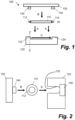
Figure 1 is a schematic exploded diagram showing a recoater carriage assembly for use in an additive manufacturing system; -
Figure 2 is a schematic exploded diagram showing the recoater carriage assembly ofFigure 1 along the cross section Z-Z; -
Figure 3 is a schematic perspective view of a carriage to carry a recoater roller for use in an additive manufacturing system according to an example; -
Figure 4 is a schematic diagram showing a recoater roller for use in a recoater carriage assembly according to an example; and -
Figure 5 is a flowchart showing a method of using a recoater carriage assembly in an additive manufacturing system according to an example. - There are many build materials from which one material may be chosen for the building of a particular part. The choice of build material may be made based on the desired properties of the part. In certain additive manufacturing systems, the build material may be changed between builds accordingly. For example, in several additive manufacturing technologies, various plastic powder types can be used as the raw build material; for example thermoplastics, such as polyamide (PA) 11, PA12, and thermoplastic polyurethane (TPU), etc. A specific powder may be chosen on the basis of desired performance, or properties and features of the final built part, to better match the requirements of the user for that specific part. During a build process, the build material may be spread layer by layer over a build area. Another component of the build device may sinter or fuse regions of the build material to build 3D parts.
- Various devices may be used to spread build material or build powder, for example rollers or blades, etc. The properties of the surface of the spreader may, at least in part, dictate the interaction of the spreader with the build material or build powder. Other factors to be considered in selection of a spreader for an additive build are the physical and chemical properties of the powder, which include the particle size of the powder, the particle shape of the powder, the cohesiveness of the powder, and the like. Therefore, certain spreaders may be more suitable for use with certain build powers than others. Undesirable effects that can result due to poor choice of spreader surface can include build powder becoming attached to, and rubbing against, the spreader surface. This may affect the quality of a layer of a build. Layer quality can include the uniformity of the layer and the flatness of the layer. A poor layer quality may have implications on the quality of the final built part.
- In the situation when different build materials are to be used for different builds, it is desirable to have a number of different spreaders for use with the different build materials in the additive manufacturing system. Furthermore, it is desirable for the process of removing a spreader and inserting a different spreader to be simple and easy for the user to perform. Complicated spreader insertion mechanisms can lead to issues such as misalignment of a spreader. Misalignment of a spreader could impact the quality of a layer of a build. It may also lead to structural complications and mechanical stresses, which may shorten the life of elements of the additive manufacturing system itself.
- Certain examples described herein help to reduce the likelihood of detrimental effects related to use of an unsuitable spreader arising during additive builds. Certain examples described herein improve the ease of engaging and disengaging a spreader with or from an additive manufacturing system. Certain examples described herein enable a user to easily remove a spreader which has become worn or damaged during a build, so that disruption to the build may be reduced. Certain examples described herein enable a user to easily remove a spreader for replacement by a different spreader prior to use of a different build material.
- A recoater carriage assembly for use in an additive manufacturing system may be used by moving a roller in a direction non-concentric to a longitudinal axis of the roller and relative to a recoater carriage to engage the roller with the carriage. In certain cases, a retainer may be moved relative to the carriage or roller, to retain the roller between the retainer and the recoater carriage. Certain cases described herein involve moving the roller in a direction orthogonal to a longitudinal axis of the roller. In certain cases, a recoater carriage assembly for use in an additive manufacturing system may be used by disengaging a first elongate recoater roller with a first surface characteristic from the recoater carriage, and engaging a second elongate recoater roller with a second surface characteristic with the recoater carriage, wherein the first surface characteristic is different from the second surface characteristic.
- Certain approaches described herein provide benefits over comparative methods that allow use of a recoater carriage assembly in an additive manufacturing system by enabling the possibility of easily replacing the spreader used in a first build that used a first powder with a different spreader for use in a second build using a second powder. The first or second powder may include PA11, PA12, TPU, PA12 with glass beads, and PA12 with flame retardant. Further, certain approaches described herein enable easier use of different powders. Certain approaches described herein provide a greater uniformity of thickness of an uppermost surface of a build powder layer during an additive build, over comparative methods. Certain approaches described herein provide a more level uppermost surface of a build powder layer during an additive build, over comparative methods. Certain approaches described herein provide benefits over comparative methods by allowing a user to more rapidly remove a recoater roller to clean or replace the roller. Certain approaches described herein provide benefits over comparative methods by enabling a user to replace parts after part failure. This in turn can improve the productivity of the additive manufacturing system.
-
Figures 1 and 2 show exploded views of arecoater carriage assembly 100 according to a non-claimed example, however, some teaching relating to this example is pertinent to the invention. Therecoater carriage assembly 100 is to help ensure additive build powder layers have improved surface characteristics, such as for example better level uniformity, in an additive manufacturing system during a build. Therecoater carriage assembly 100 comprises an elongate powderbuild material spreader 110 to spread powder build material in use. - The powder build material may comprise a polymer powder. In certain specific examples, the powder build material may comprise one or more thermoplastics, such as polyamide (PA) 11, PA12, and thermoplastic polyurethane (TPU), or the like. During a build, a fusing agent may be applied to a layer of build material after the application of fusing energy to defined areas of the layer. Similarly, in certain cases, a detailing agent may be applied to areas of a layer of build material, for example to inhibit, or modify a degree of fusing. A three-dimensional object undergoing additive manufacture may thus be built layer-by-layer from a build powder. For correct application of any fusing agents and detailing agents, it is important that the build powder layer is substantially uniformly flat.
- In the non-claimed examples according to the
Figures 1 and 2 , the elongate powderbuild material spreader 110 may spread the build powder material in use. Thespreader 100 may spread the powder layer to ensure that the thickness of the layer is regular and the upper surface of the layer is flat. Thespreader 110 may slide or press or roll the powder material to make the layer substantially uniformly flat and of a regular thickness. Thespreader 110 may, for example, be in the form of a blade which passes across the surface of the powder layer. Thespreader 110 may be, for example, a roller which rolls across the surface of the powder layer. - The
recoater carriage assembly 100 comprises arecoater carriage 120 to support thespreader 110. Thespreader 110 is engageable with thecarriage 120. Thespreader 110 is also disengageable from thecarriage 120. Thespreader 110 is to engage with, and to disengage from, therecoater carriage 120 by movement of the spreader non-concentrically to a longitudinal axis of thespreader 110. In this example, the engagement of thespreader 110 with therecoater carriage 120 enables thespreader 110 to move together with therecoater carriage 120 in use. In the specific example shown inFigure 1 , thespreader 110 is engaged with thecarriage 120 by movement of thespreader 110 in direction A relative to thecarriage 120. In a specific example, thespreader 110 is disengaged from thecarriage 120 by movement of thespreader 110 relative to thecarriage 120 in a direction opposite to direction A. In the specific example shown, the direction A is a direction orthogonal to the longitudinal axis W of thespreader 110. In other examples, thespreader 110 can be engaged and disengaged by movement in any other direction that is non-concentric to the longitudinal axis W of thespreader 110. - An advantage of this system is that a housing of the additive manufacturing system does not need to accommodate the movement of, for example, a retaining component in a direction concentric to the longitudinal axis W of the
spreader 110, such as direction C (or a direction opposite to direction C) shown inFigure 1 . If a retaining component, housed in thecarriage 120, is moved in a direction C to retain theelongate spreader 110 in thecarriage 120, then thecarriage 120 must have a width in direction C which is sufficient at least to accommodate the width of thespreader 110 and the retaining component end-to-end, and possibly also to accommodate the movement of the retaining component. In such a system, this requirement on carriage width increases the total size of the additive manufacturing system, but not the size of the build area. As such, this may be seen as wasted space. - In other comparative systems, to help avoid this wasted space, the spreader and carriage assembly need to be fully removed from the additive manufacturing system prior to movement of a retaining component in a direction C to retain the spreader in, or disengage the spreader from, the carriage. This arrangement clearly is not user-friendly, as the user wishes to interfere with as few components of the system as possible during engagement and disengagement of the spreader. Examples described herein provide features to help overcome these issues in such comparative systems.
- In certain examples, the
recoater carriage assembly 100 may comprise aretainer 130 to retain thespreader 110 in engagement with therecoater carriage 120. In the specific non-claimed example shown inFigure 1 , theretainer 130 is a lid to at least partially cover thespreader 110 when thespreader 110 is engaged with therecoater carriage 120. Thelid 130 is to be moved relative to thespreader 110 to retain thespreader 110 in engagement with therecoater carriage 120. In this example, theretainer 130 is moved in a direction B to retain thespreader 110 in engagement with therecoater carriage 120. In this example, direction B is parallel to direction A. - In the non-claimed examples of
Figures 1 and 2 , theretainer 130 comprises aresilient element 140 to bias thespreader 110 into engagement with therecoater carriage 120. In other non-claimed examples, theretainer 130 may take the form of a resilient member on thecarriage 120 or on thespreader 110 to bias thespreader 110 into engagement with therecoater carriage 120. Theresilient element 140 may be a spring or made of rubber or other resilient material, such as neoprene or polyurethane, for example. In a non-claimed example, theresilient element 140 may be positioned centrally on theretainer 130 or positioned towards one end of theretainer 130. - In certain non-claimed examples, the
retainer 130 may have a number ofresilient elements retainer 130. In a specific non-claimed example, theretainer 130 has tworesilient elements retainer 130. This arrangement provides a balance between increasing the number ofresilient elements spreader 110 when engaged with thecarriage 120, which is important for correct functioning of the system. - The
spreader 110 may, for example, be a roller and may move rotationally or laterally across the build powder layer in use to flatten the layer. Theresilient elements spreader 110 once thespreader 110 is engaged with thecarriage 120. In a specific example, thespreader 110 is a roller and the roller moves across the powder layer while counter rotating. This movement and counter rotation enables the roller to move a so-called "prism of powder" across the powder layer. The "prism of powder" is a build-up of build powder that is located in front of the roller in the direction of movement of the roller across the powder layer. In this non-claimed example, theresilient elements roller bearings carriage 120 in use. In this example, theroller bearings spreader 110, rather than counter rotation, is used to move the "prism of powder". - In certain non-claimed examples, the
recoater carriage assembly 120 may comprise at least onerecess 122. In certain non-claimed examples, thecarriage 120 may have more than onerecess recess spreader 110 in use. The, or each,recess spreader 110 in use. In the example shown inFigure 1 , thecarriage 120 comprises first andsecond recesses first recess 122 is positioned towards a first end of thecarriage 120, and thesecond recess 124 is positioned towards a second end of thecarriage 120. Therecesses Figure 1 are positioned substantially equidistantly from the longitudinal ends of thecarriage 120. In this example, thefirst recess 122 receives afirst portion 112 of thespreader 110 and thesecond recess 124 receives asecond portion 114 of thespreader 110, in use. In certain examples, the first and second portions of thespreader 110 may beprojections recesses carriage 120 in use. In certain non-claimed examples, thespreader 110 comprises at least oneprojection 112, therecoater carriage 120 comprises at least onerecess 122, and the at least oneprojection 112 of thespreader 110 projects into the at least onerecess 122 of thecarriage 120 when thespreader 110 is engaged with thecarriage 120. - In use, the
spreader 110 will contact build material, and build material may attach to thespreader 110. When a user wishes to clean or replace thespreader 110, the user is able to move theretainer 130 to permit disengagement of thespreader 100 from thecarriage 120, and then disengage thespreader 110. To avoid contact with the build material, which may be attached to thespreader 110, a user can hold theprojections spreader 110. - In certain examples, one or both of the
projections spreader 110 may comprise a drive element, such as a first gear, and the associatedrecess carriage 120 may comprise acorresponding drive mechanism 150, such as a second gear, for engagement with the drive element. In the specific non-claimed example shown inFigure 2 , theprojection 112 of thespreader 110 engages with thedrive mechanism 150 of thecarriage 120 when thespreader 110 is moved to engage with thecarriage 120. In certain examples, the drive element of thespreader 110 comprises a worm wheel and thedrive mechanism 150 of thecarriage 120 comprises a worm screw. In certain examples, the drive element of thespreader 110 and thedrive mechanism 150 of thecarriage 120 form a cam arrangement to enable thespreader 110 to move when the engagingprojection 112 of thespreader 110 is received in therecess 122. - In the non-claimed example shown in
Figure 1 , thespreader 110 has twoprojections spreader 110. The twoengaging projections spreader 110 within therecoater carriage assembly 100. Easy alignment of thespreader 110 helps the user to easily engage and disengage thespreader 110 from therecoater carriage 120, while not requiring overly accurate axial alignment. This helps to ensure that, during replacement or change-over of thespreader 110, the user is able to rapidly input thespreader 110 into therecesses spreader 110 with therecoater carriage 120. -
Figure 2 is a schematic exploded diagram showing the recoater carriage assembly ofFigure 1 along cross section Z-Z. Therecess 122, in this example, is a channel or slot in thecarriage 120. Thespreader 110 is moved in the direction A into the channel or slot to engage with thecarriage 120. In certain non-claimed examples, thechannel 122 has a drop at the end of thechannel 122. When a user inserts thespreader 110 into the channel, thespreader 110 will drop vertically as it fully engages thecarriage 120. This indicates to the user that thespreader 110 is fully in position, and helps to retain thespreader 110 positively relative to thecarriage 120. Theprojection 112 may comprise a rotatable ball bearing or similar to help slide theroller 110 along the channel orslot 122 and into the drop. This could help prevent wear of the channel orslot 122. In cases in which thespreader 110 is a roller, the rotatable ball bearing or similar may also help reduce friction to aid rotation of theroller 110 relative to thecarriage 120 in use. - In certain non-claimed examples, the
retainer 130 is moved in direction B shown inFigures 1 and 2 to retain thespreader 110 between theretainer 130 and thecarriage 120. Theresilient element 140 may bias thespreader 110 into engagement with thecarriage 120. In an example, theretainer 130 is engaged with the recoater carriage by virtue of at least one connecting member. The connecting member may be, for example, a screw, pin, bolt, rivet, or nail etc. In a specific example, the retainer is engaged with the recoater carriage by four screws. A user can remove the retainer from the recoater carriage after unscrewing the four screws using a screw driver. This enables rapid removal of the retainer during the changing of a roller, while ensuring that the retainer is well secured to the recoater carriage in use. Certain examples described herein enable a user to replace a roller in a recoater carriage in up to three minutes. - The additive manufacturing system may have an electronic display to guide a user through the process of changing a roller for ease of use. The electronic display may confirm when the roller has been successfully engaged or disengaged. A user may wish to remove the roller to perform basic maintenance on the roller, such as to renew the roller powder walls. Renewing the powder walls may be required over the life of the 3D additive manufacturing system as the roller powder walls wear out. Such renewal may involve removing the existing wall and replacing it with another wall. By providing that the spreader is easily removable and/or insertable, a user is enabled to renew the spreader without need of a repair specialist. Certain examples herein describe methods which can be performed by a user, without specialist training in the equipment, to correct errors which may be inhibiting builds.
-
Figure 3 is a schematic perspective view of a carriage to carry a recoater roller in an additive manufacturing system. Thecarriage 320 comprises aframe 321 comprising afirst support 324 and asecond support 326. Thefirst support 324 is spaced in a first direction D from thesecond support 326. Thefirst support 324 andsecond support 326 are to engage a recoater roller by movement of the recoater roller in a second direction that is different from the first direction D. The first direction D is orthogonal to the second direction. - In certain examples, the
first support 324 and thesecond support 326 are immovable relative to each other. A set distance between thefirst support 324 andsecond support 326 ensures that any roller with projections spaced this set distance apart are usable with thecarriage 320 ofFigure 3 . This allows the additive manufacturing system to accommodate many types of rollers, such as rollers with respective different surface characteristics for use in different builds. - At least one of the
first support 324 andsecond support 326 comprises a slot in thecarriage 320, as shown inFigure 3 . The slot(s) may each receive a portion of the recoater roller. Thecarriage 320 comprises aresilient retainer 330 to bias the recoater roller towards thefirst support 324 andsecond support 326, when the roller is engaged with thefirst support 324 and thesecond support 326. - In certain examples, the carriage comprises a
lid 360 to at least partially cover the roller when the roller is engaged with thefirst support 324 and thesecond support 326. In certain examples, thelid 360 comprises aretainer 365 to retain the recoater roller relative to at least one of thefirst support 324 andsecond support 326 when the roller is engaged with thefirst support 324 and thesecond support 326. Thefirst support 324 andsecond support 326 are to engage a recoater roller by movement of the recoater roller in a second direction. Thelid 360 andretainer 365 are moved in a direction E towards thesupports retainer 365 and theframe 321 in use. In certain examples, the direction E is parallel to the second direction. - In certain examples, the carriage comprises a
gear 350 to engage with a gear of the recoater roller when the recoater roller is engaged with thefirst support 324 and thesecond support 326. In an example, thegear 350, shown schematically inFigure 3 , is positioned adjacent or at thefirst support 324. In certain examples, the carriage comprises afirst gear 350 and asecond gear 352. In an example, thefirst gear 350 is positioned adjacent or at thefirst support 324 and thesecond gear 352 is positioned adjacent or at thesecond support 326. The first andsecond gears -
Figure 4 shows an example of aspreader 400. In certain examples, thespreader 400 comprises aspreader surface 410 to contact the build material in use. In certain examples, thespreader 400 comprisesend portions spreader surface 410 is greater than the dimension or height H" of theend portions spreader surface 410 has a width W' and thespreader 400 has a total width W". The supports of a recoater carriage for use with thespreader 400 must be set at least the width W' of the main spreadingsurface 410 apart but not more than the width W" of thespreader 400 apart. -
Figure 5 is a flowchart showing amethod 500 of using a recoater carriage assembly in an additive manufacturing system according to an example. This method may be used with therecoater carriage assembly 100 ofFigure 1 (not according to the appended claims) or upon a different system. - At
block 505, a first recoater roller is disengaged from a recoater carriage. In a specific example, the first recoater roller is an elongate recoater roller. In a non-claimed example, the direction in which the first elongate recoater roller is moved to be disengaged from the recoater carriage is opposite to the direction A shown inFigure 1 . According to the invention, the direction in which the first elongate recoater roller is moved is a direction orthogonal to a longitudinal axis of the first elongate recoater roller. - At
block 510, a second elongate recoater roller is moved in a direction non-concentric to a longitudinal axis of the second elongate recoater roller and relative to the recoater carriage, to engage the second elongate recoater roller with the recoater carriage. In this example, the engagement of the second elongate recoater roller with the recoater carriage enables the second elongate recoater roller to move together with the recoater carriage in use. In a non-claimed specific example, the second elongate recoater roller is moved in the direction A shown inFigure 1 . According to the invention, the direction in which the second elongate recoater roller is moved is a direction orthogonal to a longitudinal axis of the second elongate recoater roller. - In an example, the first recoater roller has a surface characteristic which differs from the surface characteristic of the second recoater roller. The surface characteristic may be, for example, smoothness, texture or absorbency, or the like. The surface characteristic may be affected or determined by use of grooves on the surface of a roller used to create a rough surface. The type of grooves and dimensions of the grooves will create different types of surfaces with different characteristics. This may result in a surface that is more suited for use with one type of powder over another type of powder. The surface characteristic may be affected or determined by one or more factors including the surface material, the surface finish and the surface coating (if provided).
- Build layers in additive manufacturing systems may be around 100 microns thick. The size of build powder particles may be around 50 microns. As such, it may be beneficial to ensure build powder does not attach to rollers during use. Rollers with different respective surface characteristics may interact differently with any given build powder. A first roller with a certain surface characteristic may interact with a given build powder better than another roller in which the surface characteristic differs from that of the first roller. As such, a user may wish to use a first roller with a particular surface characteristic with a first build powder, and a second roller with a second build powder, wherein the surface characteristic of the second roller differs from that of the first roller. This may help to prevent or reduce powder attaching to rollers, and may help the flattening of build layers prior to builds. Examples described herein enable a user to rapidly and easily change rollers that are held by a carriage.
Claims (8)
- A carriage to carry a recoater roller for use in an additive manufacturing system, the carriage (320) comprising:a frame (321) comprising a first support (324) and a second support (326), wherein the first support is spaced in a first direction (D) from the second support, and comprising a resilient retainer (330) to bias the recoater roller (410) towards the first support (324) and second support (326) when the roller is engaged with the first support and the second support;wherein at least one of the first support (324) and the second support (326) has a slot to engage with the recoater roller by movement of the recoater roller in a second direction (E) that is different from the first direction (D); andwherein the first direction (D) is orthogonal to the second direction (E).
- The carriage of claim 1, comprising a lid (360) to at least partially cover the roller (410) when the roller is engaged with the first support (324) and the second support (326);
wherein the lid (360) comprises a retainer (365) to retain the recoater roller (410) relative to at least one of the first support (324) and second support (326) when the roller is engaged with the first support and the second support. - The carriage of claim 1, wherein the carriage (320) comprises a gear to engage with a gear of the recoater roller (410) when the recoater roller is engaged with the first support and the second support.
- The carriage of claim 1, wherein the first support (324) and the second support (326) are immovable relative to each other.
- A recoater carriage assembly for use in an additive manufacturing system, the recoater carriage assembly comprising:a recoater roller; anda carriage to carry a recoater roller as claimed in claim 1.
- The recoater carriage assembly of claim 5, whereinthe recoater roller (410) comprises at least one projection (414, 416), andthe at least one projection of the recoater roller projects into the at least one slot of the carriage (320) when the recoater roller (410) is engaged with the carriage.
- A method of using a recoater carriage assembly according to claim 5 in an additive manufacturing system, the method comprising:moving (505) the recoater roller (410) relative to the slot to engage with the recoater carriage, wherein the moving (505) of the recoater roller to engage with the recoater carriage is in the second direction (E); andusing a resilient retainer (330) to bias the recoater roller (410) towards the first support (324) and second support (326) when the roller is engaged with the first support and the second support.
- The method of claim 7, wherein the recoater roller is a first roller;wherein the method comprises, after disengaging the first roller from the recoater carriage, engaging with the recoater carriage a second elongate recoater roller (510); andwherein a surface characteristic of the first and second rollers differs between the first and second rollers.
Applications Claiming Priority (1)
| Application Number | Priority Date | Filing Date | Title |
|---|---|---|---|
| PCT/US2016/057325 WO2018074991A1 (en) | 2016-10-17 | 2016-10-17 | Recoater carriage |
Publications (3)
| Publication Number | Publication Date |
|---|---|
| EP3487682A1 EP3487682A1 (en) | 2019-05-29 |
| EP3487682A4 EP3487682A4 (en) | 2020-03-11 |
| EP3487682B1 true EP3487682B1 (en) | 2025-03-12 |
Family
ID=62018746
Family Applications (1)
| Application Number | Title | Priority Date | Filing Date |
|---|---|---|---|
| EP16919317.4A Active EP3487682B1 (en) | 2016-10-17 | 2016-10-17 | Recoater carriage |
Country Status (4)
| Country | Link |
|---|---|
| US (1) | US11267197B2 (en) |
| EP (1) | EP3487682B1 (en) |
| CN (1) | CN109641390B (en) |
| WO (1) | WO2018074991A1 (en) |
Families Citing this family (11)
| Publication number | Priority date | Publication date | Assignee | Title |
|---|---|---|---|---|
| CN114126842A (en) * | 2019-05-28 | 2022-03-01 | 伏尔肯模型公司 | Recoater system for additive manufacturing |
| JP7578810B2 (en) | 2020-10-20 | 2024-11-06 | ゼネラル・エレクトリック・カンパニイ | Print assembly and method for circulating binder material - Patents.com |
| JP7525738B2 (en) | 2020-10-20 | 2024-07-30 | ゼネラル・エレクトリック・カンパニイ | Method for forming an object and additive manufacturing system |
| WO2022087048A1 (en) | 2020-10-21 | 2022-04-28 | General Electric Company | Material supply systems for additive manufacturing and methods for using the same |
| EP4232265A1 (en) | 2020-10-21 | 2023-08-30 | General Electric Company | Material supply systems and methods for using the same |
| EP4232267A1 (en) | 2020-10-21 | 2023-08-30 | General Electric Company | Material supply system and method for using the same |
| WO2022093943A1 (en) | 2020-10-29 | 2022-05-05 | General Electric Company | Additive manufacturing apparatuses with removable build boxes and lid management systems |
| WO2022093914A1 (en) | 2020-10-29 | 2022-05-05 | General Electric Company | Additive manufacturing apparatuses and methods for using the same |
| EP4237226A1 (en) | 2020-10-29 | 2023-09-06 | General Electric Company | Print head assembly and methods for using the same |
| US12533848B2 (en) | 2020-10-29 | 2026-01-27 | General Electric Company | Additive manufacturing apparatuses with removable build boxes and build box management systems |
| US11718026B1 (en) | 2022-07-20 | 2023-08-08 | General Electric Company | Recoat assemblies for additive manufacturing systems and methods of using the same |
Family Cites Families (17)
| Publication number | Priority date | Publication date | Assignee | Title |
|---|---|---|---|---|
| US20050104241A1 (en) | 2000-01-18 | 2005-05-19 | Objet Geometried Ltd. | Apparatus and method for three dimensional model printing |
| US7384255B2 (en) | 2005-07-01 | 2008-06-10 | Stratasys, Inc. | Rapid prototyping system with controlled material feedstock |
| US7585450B2 (en) * | 2005-09-30 | 2009-09-08 | 3D Systems, Inc. | Rapid prototyping and manufacturing system and method |
| DE102006055074A1 (en) * | 2006-11-22 | 2008-06-19 | Eos Gmbh Electro Optical Systems | Apparatus for layering a three-dimensional object and method for supplying building material |
| EP2447044B1 (en) | 2010-11-01 | 2014-01-08 | DSM IP Assets B.V. | Apparatus and method of additive fabrication comprising a reciprocable foil guiding system |
| CA2900297A1 (en) * | 2013-03-15 | 2014-09-18 | Matterfab Corp. | Cartridge for an additive manufacturing apparatus and method |
| GB201308565D0 (en) | 2013-05-13 | 2013-06-19 | Blueprinter Aps | Three-dimensional printer |
| CN203470903U (en) | 2013-07-31 | 2014-03-12 | 济南大学 | Quick forming powder spreading device |
| CN204035564U (en) | 2014-04-03 | 2014-12-24 | 上海航天设备制造总厂 | A kind of power spreading device for fast changeable roll type 3D printer |
| JP6458416B2 (en) | 2014-09-16 | 2019-01-30 | 株式会社リコー | 3D modeling apparatus and 3D manufacturing method |
| WO2016084350A1 (en) | 2014-11-28 | 2016-06-02 | Canon Kabushiki Kaisha | Forming apparatus, three-dimensional forming method, and object formed by using the method |
| EP3085517B1 (en) | 2015-02-27 | 2019-05-22 | Technology Research Association For Future Additive Manufacturing | Powder recoater |
| CN204844878U (en) | 2015-07-23 | 2015-12-09 | 南京中科煜宸激光技术有限公司 | A spread powder device for quick shaping manufacturing |
| WO2017040521A1 (en) * | 2015-09-03 | 2017-03-09 | The Exone Company | Selectively activated mesh discharge powder recoater for three-dimensional printing |
| EP3349968A4 (en) * | 2015-09-16 | 2019-08-21 | Applied Materials, Inc. | ADJUSTABLE Z AXIS PRINTING HEAD MODULE FOR ADDITIVE MANUFACTURING SYSTEM |
| RU165868U1 (en) | 2015-12-29 | 2016-11-10 | Федеральное государственное бюджетное образовательное учреждение высшего образования "Московский государственный технологический университет "СТАНКИН" (ФГБОУ ВО "МГТУ "СТАНКИН") | DEVICE FOR PRODUCTION OF POWDER MATERIALS |
| CN205464327U (en) | 2016-01-12 | 2016-08-17 | 湖南华曙高科技有限责任公司 | Shop's powder device of selectivity laser sintering equipment |
-
2016
- 2016-10-17 US US16/089,859 patent/US11267197B2/en active Active
- 2016-10-17 CN CN201680088213.1A patent/CN109641390B/en active Active
- 2016-10-17 WO PCT/US2016/057325 patent/WO2018074991A1/en not_active Ceased
- 2016-10-17 EP EP16919317.4A patent/EP3487682B1/en active Active
Also Published As
| Publication number | Publication date |
|---|---|
| CN109641390B (en) | 2022-04-01 |
| EP3487682A1 (en) | 2019-05-29 |
| CN109641390A (en) | 2019-04-16 |
| WO2018074991A1 (en) | 2018-04-26 |
| US11267197B2 (en) | 2022-03-08 |
| US20200298474A1 (en) | 2020-09-24 |
| EP3487682A4 (en) | 2020-03-11 |
Similar Documents
| Publication | Publication Date | Title |
|---|---|---|
| US11267197B2 (en) | Recoater carriage | |
| US11958162B2 (en) | CMP pad construction with composite material properties using additive manufacturing processes | |
| CN101213060B (en) | Rapid prototyping system with controlled material feed | |
| KR101681615B1 (en) | Roller frame | |
| US20200198319A1 (en) | Apparatus and method for fabrication of three dimensional objects | |
| WO2017211467A1 (en) | Tool, device, and method for polishing lenses | |
| CN102574292A (en) | Methods and arrangements relating to edge machining of building panels | |
| US20190337205A1 (en) | Interchangeable mold for creation of injection molded components | |
| US9782904B2 (en) | Apparatus and method for cutting facestock | |
| DE102017125602A1 (en) | Gear processing device and gear processing method | |
| DE102017124177A1 (en) | Tool change in generative production | |
| CN101171532A (en) | Microreplicated articles with reduced moiré surfaces | |
| WO2018073700A1 (en) | Method and device for producing a three-dimensional object | |
| WO2017088754A1 (en) | Filament drive assembly for additive manufacturing device | |
| DE112007003203T5 (en) | Apparatus for producing a liquid silicone foam in roll form | |
| DE102012004563A1 (en) | Processing device for use with construction machine for automatically processing surface and edges of e.g. thick plate, has processing disk rotated during machining process for processing workpiece and moved along processing path | |
| DE112015005672T5 (en) | Processing tool for an optical element and manufacturing method for an optical element | |
| DE102005040237B4 (en) | embossing calender | |
| DE10134185A1 (en) | Straightforward guidance | |
| WO2012069168A2 (en) | Apparatus and process for machining an optical lens | |
| DE102012216724B4 (en) | Method and device for polishing spectacle lenses and casting molds for spectacle lens production, as well as corresponding method for producing spectacle lenses and casting molds for spectacle lens production | |
| US20060082052A1 (en) | Sheet feed roll | |
| DE102009023146A1 (en) | Film-forming device and film-forming method | |
| DE102015112527A1 (en) | Apparatus and method for pouring a ring-shaped plastic frame into a recess of a rotor disk of a double-side processing machine | |
| WO2017034386A2 (en) | An improved former holder assembly |
Legal Events
| Date | Code | Title | Description |
|---|---|---|---|
| STAA | Information on the status of an ep patent application or granted ep patent |
Free format text: STATUS: THE INTERNATIONAL PUBLICATION HAS BEEN MADE |
|
| PUAI | Public reference made under article 153(3) epc to a published international application that has entered the european phase |
Free format text: ORIGINAL CODE: 0009012 |
|
| STAA | Information on the status of an ep patent application or granted ep patent |
Free format text: STATUS: REQUEST FOR EXAMINATION WAS MADE |
|
| 17P | Request for examination filed |
Effective date: 20190222 |
|
| AK | Designated contracting states |
Kind code of ref document: A1 Designated state(s): AL AT BE BG CH CY CZ DE DK EE ES FI FR GB GR HR HU IE IS IT LI LT LU LV MC MK MT NL NO PL PT RO RS SE SI SK SM TR |
|
| AX | Request for extension of the european patent |
Extension state: BA ME |
|
| DAV | Request for validation of the european patent (deleted) | ||
| DAX | Request for extension of the european patent (deleted) | ||
| A4 | Supplementary search report drawn up and despatched |
Effective date: 20200212 |
|
| RIC1 | Information provided on ipc code assigned before grant |
Ipc: B29C 64/153 20170101ALI20200206BHEP Ipc: B29C 64/165 20170101ALI20200206BHEP Ipc: B22F 3/105 20060101ALI20200206BHEP Ipc: B29C 64/209 20170101ALI20200206BHEP Ipc: B33Y 30/00 20150101ALI20200206BHEP Ipc: B29C 64/236 20170101ALI20200206BHEP Ipc: B29C 64/205 20170101AFI20200206BHEP |
|
| STAA | Information on the status of an ep patent application or granted ep patent |
Free format text: STATUS: EXAMINATION IS IN PROGRESS |
|
| 17Q | First examination report despatched |
Effective date: 20211019 |
|
| GRAP | Despatch of communication of intention to grant a patent |
Free format text: ORIGINAL CODE: EPIDOSNIGR1 |
|
| STAA | Information on the status of an ep patent application or granted ep patent |
Free format text: STATUS: GRANT OF PATENT IS INTENDED |
|
| INTG | Intention to grant announced |
Effective date: 20241223 |
|
| RAP3 | Party data changed (applicant data changed or rights of an application transferred) |
Owner name: HEWLETT-PACKARD DEVELOPMENT COMPANY, L.P. |
|
| RIN1 | Information on inventor provided before grant (corrected) |
Inventor name: BRUGUE, JOAQUIM Inventor name: MOSQUERA, GERARD Inventor name: GIMENEZ, JORDI |
|
| GRAS | Grant fee paid |
Free format text: ORIGINAL CODE: EPIDOSNIGR3 |
|
| GRAA | (expected) grant |
Free format text: ORIGINAL CODE: 0009210 |
|
| STAA | Information on the status of an ep patent application or granted ep patent |
Free format text: STATUS: THE PATENT HAS BEEN GRANTED |
|
| AK | Designated contracting states |
Kind code of ref document: B1 Designated state(s): AL AT BE BG CH CY CZ DE DK EE ES FI FR GB GR HR HU IE IS IT LI LT LU LV MC MK MT NL NO PL PT RO RS SE SI SK SM TR |
|
| REG | Reference to a national code |
Ref country code: GB Ref legal event code: FG4D |
|
| REG | Reference to a national code |
Ref country code: CH Ref legal event code: EP |
|
| REG | Reference to a national code |
Ref country code: DE Ref legal event code: R096 Ref document number: 602016091564 Country of ref document: DE |
|
| REG | Reference to a national code |
Ref country code: IE Ref legal event code: FG4D |
|
| RAP2 | Party data changed (patent owner data changed or rights of a patent transferred) |
Owner name: PERIDOT PRINT LLC |
|
| PG25 | Lapsed in a contracting state [announced via postgrant information from national office to epo] |
Ref country code: RS Free format text: LAPSE BECAUSE OF FAILURE TO SUBMIT A TRANSLATION OF THE DESCRIPTION OR TO PAY THE FEE WITHIN THE PRESCRIBED TIME-LIMIT Effective date: 20250612 |
|
| PG25 | Lapsed in a contracting state [announced via postgrant information from national office to epo] |
Ref country code: FI Free format text: LAPSE BECAUSE OF FAILURE TO SUBMIT A TRANSLATION OF THE DESCRIPTION OR TO PAY THE FEE WITHIN THE PRESCRIBED TIME-LIMIT Effective date: 20250312 |
|
| PG25 | Lapsed in a contracting state [announced via postgrant information from national office to epo] |
Ref country code: ES Free format text: LAPSE BECAUSE OF FAILURE TO SUBMIT A TRANSLATION OF THE DESCRIPTION OR TO PAY THE FEE WITHIN THE PRESCRIBED TIME-LIMIT Effective date: 20250312 |
|
| REG | Reference to a national code |
Ref country code: LT Ref legal event code: MG9D |
|
| PG25 | Lapsed in a contracting state [announced via postgrant information from national office to epo] |
Ref country code: NO Free format text: LAPSE BECAUSE OF FAILURE TO SUBMIT A TRANSLATION OF THE DESCRIPTION OR TO PAY THE FEE WITHIN THE PRESCRIBED TIME-LIMIT Effective date: 20250612 |
|
| PG25 | Lapsed in a contracting state [announced via postgrant information from national office to epo] |
Ref country code: HR Free format text: LAPSE BECAUSE OF FAILURE TO SUBMIT A TRANSLATION OF THE DESCRIPTION OR TO PAY THE FEE WITHIN THE PRESCRIBED TIME-LIMIT Effective date: 20250312 |
|
| REG | Reference to a national code |
Ref country code: NL Ref legal event code: MP Effective date: 20250312 |
|
| PG25 | Lapsed in a contracting state [announced via postgrant information from national office to epo] |
Ref country code: LV Free format text: LAPSE BECAUSE OF FAILURE TO SUBMIT A TRANSLATION OF THE DESCRIPTION OR TO PAY THE FEE WITHIN THE PRESCRIBED TIME-LIMIT Effective date: 20250312 |
|
| PG25 | Lapsed in a contracting state [announced via postgrant information from national office to epo] |
Ref country code: GR Free format text: LAPSE BECAUSE OF FAILURE TO SUBMIT A TRANSLATION OF THE DESCRIPTION OR TO PAY THE FEE WITHIN THE PRESCRIBED TIME-LIMIT Effective date: 20250613 Ref country code: BG Free format text: LAPSE BECAUSE OF FAILURE TO SUBMIT A TRANSLATION OF THE DESCRIPTION OR TO PAY THE FEE WITHIN THE PRESCRIBED TIME-LIMIT Effective date: 20250312 |
|
| REG | Reference to a national code |
Ref country code: DE Ref legal event code: R081 Ref document number: 602016091564 Country of ref document: DE Owner name: PERIDOT PRINT LLC, PALO ALTO, US Free format text: FORMER OWNER: HEWLETT-PACKARD DEVELOPMENT COMPANY, L.P., SPRING, TX, US |
|
| REG | Reference to a national code |
Ref country code: AT Ref legal event code: MK05 Ref document number: 1774675 Country of ref document: AT Kind code of ref document: T Effective date: 20250312 |
|
| PG25 | Lapsed in a contracting state [announced via postgrant information from national office to epo] |
Ref country code: NL Free format text: LAPSE BECAUSE OF FAILURE TO SUBMIT A TRANSLATION OF THE DESCRIPTION OR TO PAY THE FEE WITHIN THE PRESCRIBED TIME-LIMIT Effective date: 20250312 |
|
| REG | Reference to a national code |
Ref country code: GB Ref legal event code: 732E Free format text: REGISTERED BETWEEN 20250807 AND 20250813 |
|
| PG25 | Lapsed in a contracting state [announced via postgrant information from national office to epo] |
Ref country code: SE Free format text: LAPSE BECAUSE OF FAILURE TO SUBMIT A TRANSLATION OF THE DESCRIPTION OR TO PAY THE FEE WITHIN THE PRESCRIBED TIME-LIMIT Effective date: 20250312 |
|
| PG25 | Lapsed in a contracting state [announced via postgrant information from national office to epo] |
Ref country code: SM Free format text: LAPSE BECAUSE OF FAILURE TO SUBMIT A TRANSLATION OF THE DESCRIPTION OR TO PAY THE FEE WITHIN THE PRESCRIBED TIME-LIMIT Effective date: 20250312 |
|
| PG25 | Lapsed in a contracting state [announced via postgrant information from national office to epo] |
Ref country code: PT Free format text: LAPSE BECAUSE OF FAILURE TO SUBMIT A TRANSLATION OF THE DESCRIPTION OR TO PAY THE FEE WITHIN THE PRESCRIBED TIME-LIMIT Effective date: 20250714 |
|
| PG25 | Lapsed in a contracting state [announced via postgrant information from national office to epo] |
Ref country code: PL Free format text: LAPSE BECAUSE OF FAILURE TO SUBMIT A TRANSLATION OF THE DESCRIPTION OR TO PAY THE FEE WITHIN THE PRESCRIBED TIME-LIMIT Effective date: 20250312 Ref country code: IT Free format text: LAPSE BECAUSE OF FAILURE TO SUBMIT A TRANSLATION OF THE DESCRIPTION OR TO PAY THE FEE WITHIN THE PRESCRIBED TIME-LIMIT Effective date: 20250312 |
|
| PGFP | Annual fee paid to national office [announced via postgrant information from national office to epo] |
Ref country code: GB Payment date: 20250923 Year of fee payment: 10 |
|
| PG25 | Lapsed in a contracting state [announced via postgrant information from national office to epo] |
Ref country code: AT Free format text: LAPSE BECAUSE OF FAILURE TO SUBMIT A TRANSLATION OF THE DESCRIPTION OR TO PAY THE FEE WITHIN THE PRESCRIBED TIME-LIMIT Effective date: 20250312 |
|
| PGFP | Annual fee paid to national office [announced via postgrant information from national office to epo] |
Ref country code: FR Payment date: 20250924 Year of fee payment: 10 |
|
| PG25 | Lapsed in a contracting state [announced via postgrant information from national office to epo] |
Ref country code: EE Free format text: LAPSE BECAUSE OF FAILURE TO SUBMIT A TRANSLATION OF THE DESCRIPTION OR TO PAY THE FEE WITHIN THE PRESCRIBED TIME-LIMIT Effective date: 20250312 Ref country code: CZ Free format text: LAPSE BECAUSE OF FAILURE TO SUBMIT A TRANSLATION OF THE DESCRIPTION OR TO PAY THE FEE WITHIN THE PRESCRIBED TIME-LIMIT Effective date: 20250312 |
|
| PG25 | Lapsed in a contracting state [announced via postgrant information from national office to epo] |
Ref country code: RO Free format text: LAPSE BECAUSE OF FAILURE TO SUBMIT A TRANSLATION OF THE DESCRIPTION OR TO PAY THE FEE WITHIN THE PRESCRIBED TIME-LIMIT Effective date: 20250312 |
|
| PG25 | Lapsed in a contracting state [announced via postgrant information from national office to epo] |
Ref country code: SK Free format text: LAPSE BECAUSE OF FAILURE TO SUBMIT A TRANSLATION OF THE DESCRIPTION OR TO PAY THE FEE WITHIN THE PRESCRIBED TIME-LIMIT Effective date: 20250312 |
|
| PG25 | Lapsed in a contracting state [announced via postgrant information from national office to epo] |
Ref country code: IS Free format text: LAPSE BECAUSE OF FAILURE TO SUBMIT A TRANSLATION OF THE DESCRIPTION OR TO PAY THE FEE WITHIN THE PRESCRIBED TIME-LIMIT Effective date: 20250712 |
|
| REG | Reference to a national code |
Ref country code: DE Ref legal event code: R097 Ref document number: 602016091564 Country of ref document: DE |
|
| PGFP | Annual fee paid to national office [announced via postgrant information from national office to epo] |
Ref country code: DE Payment date: 20250923 Year of fee payment: 10 |
|
| PG25 | Lapsed in a contracting state [announced via postgrant information from national office to epo] |
Ref country code: DK Free format text: LAPSE BECAUSE OF FAILURE TO SUBMIT A TRANSLATION OF THE DESCRIPTION OR TO PAY THE FEE WITHIN THE PRESCRIBED TIME-LIMIT Effective date: 20250312 |
|
| PLBE | No opposition filed within time limit |
Free format text: ORIGINAL CODE: 0009261 |
|
| STAA | Information on the status of an ep patent application or granted ep patent |
Free format text: STATUS: NO OPPOSITION FILED WITHIN TIME LIMIT |
|
| REG | Reference to a national code |
Ref country code: CH Ref legal event code: L10 Free format text: ST27 STATUS EVENT CODE: U-0-0-L10-L00 (AS PROVIDED BY THE NATIONAL OFFICE) Effective date: 20260121 |
|
| 26N | No opposition filed |
Effective date: 20251215 |
|
| REG | Reference to a national code |
Ref country code: CH Ref legal event code: H13 Free format text: ST27 STATUS EVENT CODE: U-0-0-H10-H13 (AS PROVIDED BY THE NATIONAL OFFICE) Effective date: 20260527 |
|
| PG25 | Lapsed in a contracting state [announced via postgrant information from national office to epo] |
Ref country code: LU Free format text: LAPSE BECAUSE OF NON-PAYMENT OF DUE FEES Effective date: 20251017 |
|
| REG | Reference to a national code |
Ref country code: BE Ref legal event code: MM Effective date: 20251031 |
|
| PG25 | Lapsed in a contracting state [announced via postgrant information from national office to epo] |
Ref country code: LT Free format text: LAPSE BECAUSE OF FAILURE TO SUBMIT A TRANSLATION OF THE DESCRIPTION OR TO PAY THE FEE WITHIN THE PRESCRIBED TIME-LIMIT Effective date: 20250312 |
|
| PG25 | Lapsed in a contracting state [announced via postgrant information from national office to epo] |
Ref country code: MC Free format text: LAPSE BECAUSE OF FAILURE TO SUBMIT A TRANSLATION OF THE DESCRIPTION OR TO PAY THE FEE WITHIN THE PRESCRIBED TIME-LIMIT Effective date: 20250312 |
|
| PG25 | Lapsed in a contracting state [announced via postgrant information from national office to epo] |
Ref country code: CH Free format text: LAPSE BECAUSE OF NON-PAYMENT OF DUE FEES Effective date: 20251031 Ref country code: BE Free format text: LAPSE BECAUSE OF NON-PAYMENT OF DUE FEES Effective date: 20251031 |