EP3487280B1 - Haptic driving guidance system - Google Patents
Haptic driving guidance system Download PDFInfo
- Publication number
- EP3487280B1 EP3487280B1 EP17831480.3A EP17831480A EP3487280B1 EP 3487280 B1 EP3487280 B1 EP 3487280B1 EP 17831480 A EP17831480 A EP 17831480A EP 3487280 B1 EP3487280 B1 EP 3487280B1
- Authority
- EP
- European Patent Office
- Prior art keywords
- haptic output
- haptic
- user
- output devices
- vehicle
- Prior art date
- Legal status (The legal status is an assumption and is not a legal conclusion. Google has not performed a legal analysis and makes no representation as to the accuracy of the status listed.)
- Active
Links
- 238000000034 method Methods 0.000 claims description 38
- 238000004590 computer program Methods 0.000 claims description 7
- 230000008859 change Effects 0.000 claims description 4
- 238000002604 ultrasonography Methods 0.000 claims description 2
- 230000035807 sensation Effects 0.000 description 85
- 210000002683 foot Anatomy 0.000 description 18
- 230000005540 biological transmission Effects 0.000 description 13
- 238000012545 processing Methods 0.000 description 13
- 230000000007 visual effect Effects 0.000 description 13
- 238000010586 diagram Methods 0.000 description 12
- 238000003491 array Methods 0.000 description 6
- 230000001149 cognitive effect Effects 0.000 description 6
- 230000006870 function Effects 0.000 description 5
- 230000009471 action Effects 0.000 description 4
- 230000006399 behavior Effects 0.000 description 4
- 210000000245 forearm Anatomy 0.000 description 4
- 238000013459 approach Methods 0.000 description 3
- 230000008901 benefit Effects 0.000 description 3
- 238000004891 communication Methods 0.000 description 3
- 210000004247 hand Anatomy 0.000 description 3
- 238000012544 monitoring process Methods 0.000 description 3
- 210000000707 wrist Anatomy 0.000 description 3
- 210000003423 ankle Anatomy 0.000 description 2
- 230000000994 depressogenic effect Effects 0.000 description 2
- 210000003811 finger Anatomy 0.000 description 2
- 230000007246 mechanism Effects 0.000 description 2
- 230000003287 optical effect Effects 0.000 description 2
- 230000007704 transition Effects 0.000 description 2
- 230000001133 acceleration Effects 0.000 description 1
- 210000004712 air sac Anatomy 0.000 description 1
- 230000001351 cycling effect Effects 0.000 description 1
- 230000001066 destructive effect Effects 0.000 description 1
- 230000005520 electrodynamics Effects 0.000 description 1
- 239000000446 fuel Substances 0.000 description 1
- 230000003993 interaction Effects 0.000 description 1
- 210000002414 leg Anatomy 0.000 description 1
- 238000012986 modification Methods 0.000 description 1
- 230000004048 modification Effects 0.000 description 1
- 239000013307 optical fiber Substances 0.000 description 1
- 230000037361 pathway Effects 0.000 description 1
- 230000008569 process Effects 0.000 description 1
- 239000004065 semiconductor Substances 0.000 description 1
Images


Classifications
-
- G—PHYSICS
- G06—COMPUTING; CALCULATING OR COUNTING
- G06F—ELECTRIC DIGITAL DATA PROCESSING
- G06F3/00—Input arrangements for transferring data to be processed into a form capable of being handled by the computer; Output arrangements for transferring data from processing unit to output unit, e.g. interface arrangements
- G06F3/01—Input arrangements or combined input and output arrangements for interaction between user and computer
- G06F3/016—Input arrangements with force or tactile feedback as computer generated output to the user
-
- B60K35/10—
-
- B—PERFORMING OPERATIONS; TRANSPORTING
- B60—VEHICLES IN GENERAL
- B60Q—ARRANGEMENT OF SIGNALLING OR LIGHTING DEVICES, THE MOUNTING OR SUPPORTING THEREOF OR CIRCUITS THEREFOR, FOR VEHICLES IN GENERAL
- B60Q9/00—Arrangement or adaptation of signal devices not provided for in one of main groups B60Q1/00 - B60Q7/00, e.g. haptic signalling
-
- B—PERFORMING OPERATIONS; TRANSPORTING
- B60—VEHICLES IN GENERAL
- B60W—CONJOINT CONTROL OF VEHICLE SUB-UNITS OF DIFFERENT TYPE OR DIFFERENT FUNCTION; CONTROL SYSTEMS SPECIALLY ADAPTED FOR HYBRID VEHICLES; ROAD VEHICLE DRIVE CONTROL SYSTEMS FOR PURPOSES NOT RELATED TO THE CONTROL OF A PARTICULAR SUB-UNIT
- B60W50/00—Details of control systems for road vehicle drive control not related to the control of a particular sub-unit, e.g. process diagnostic or vehicle driver interfaces
- B60W50/08—Interaction between the driver and the control system
- B60W50/14—Means for informing the driver, warning the driver or prompting a driver intervention
- B60W50/16—Tactile feedback to the driver, e.g. vibration or force feedback to the driver on the steering wheel or the accelerator pedal
-
- G—PHYSICS
- G06—COMPUTING; CALCULATING OR COUNTING
- G06F—ELECTRIC DIGITAL DATA PROCESSING
- G06F3/00—Input arrangements for transferring data to be processed into a form capable of being handled by the computer; Output arrangements for transferring data from processing unit to output unit, e.g. interface arrangements
- G06F3/01—Input arrangements or combined input and output arrangements for interaction between user and computer
- G06F3/03—Arrangements for converting the position or the displacement of a member into a coded form
- G06F3/041—Digitisers, e.g. for touch screens or touch pads, characterised by the transducing means
- G06F3/0414—Digitisers, e.g. for touch screens or touch pads, characterised by the transducing means using force sensing means to determine a position
-
- G—PHYSICS
- G06—COMPUTING; CALCULATING OR COUNTING
- G06F—ELECTRIC DIGITAL DATA PROCESSING
- G06F3/00—Input arrangements for transferring data to be processed into a form capable of being handled by the computer; Output arrangements for transferring data from processing unit to output unit, e.g. interface arrangements
- G06F3/01—Input arrangements or combined input and output arrangements for interaction between user and computer
- G06F3/048—Interaction techniques based on graphical user interfaces [GUI]
- G06F3/0487—Interaction techniques based on graphical user interfaces [GUI] using specific features provided by the input device, e.g. functions controlled by the rotation of a mouse with dual sensing arrangements, or of the nature of the input device, e.g. tap gestures based on pressure sensed by a digitiser
- G06F3/0488—Interaction techniques based on graphical user interfaces [GUI] using specific features provided by the input device, e.g. functions controlled by the rotation of a mouse with dual sensing arrangements, or of the nature of the input device, e.g. tap gestures based on pressure sensed by a digitiser using a touch-screen or digitiser, e.g. input of commands through traced gestures
-
- G—PHYSICS
- G06—COMPUTING; CALCULATING OR COUNTING
- G06F—ELECTRIC DIGITAL DATA PROCESSING
- G06F9/00—Arrangements for program control, e.g. control units
- G06F9/06—Arrangements for program control, e.g. control units using stored programs, i.e. using an internal store of processing equipment to receive or retain programs
- G06F9/30—Arrangements for executing machine instructions, e.g. instruction decode
- G06F9/30003—Arrangements for executing specific machine instructions
- G06F9/3004—Arrangements for executing specific machine instructions to perform operations on memory
-
- H—ELECTRICITY
- H04—ELECTRIC COMMUNICATION TECHNIQUE
- H04R—LOUDSPEAKERS, MICROPHONES, GRAMOPHONE PICK-UPS OR LIKE ACOUSTIC ELECTROMECHANICAL TRANSDUCERS; DEAF-AID SETS; PUBLIC ADDRESS SYSTEMS
- H04R1/00—Details of transducers, loudspeakers or microphones
- H04R1/46—Special adaptations for use as contact microphones, e.g. on musical instrument, on stethoscope
-
- B—PERFORMING OPERATIONS; TRANSPORTING
- B60—VEHICLES IN GENERAL
- B60W—CONJOINT CONTROL OF VEHICLE SUB-UNITS OF DIFFERENT TYPE OR DIFFERENT FUNCTION; CONTROL SYSTEMS SPECIALLY ADAPTED FOR HYBRID VEHICLES; ROAD VEHICLE DRIVE CONTROL SYSTEMS FOR PURPOSES NOT RELATED TO THE CONTROL OF A PARTICULAR SUB-UNIT
- B60W2552/00—Input parameters relating to infrastructure
-
- B—PERFORMING OPERATIONS; TRANSPORTING
- B60—VEHICLES IN GENERAL
- B60W—CONJOINT CONTROL OF VEHICLE SUB-UNITS OF DIFFERENT TYPE OR DIFFERENT FUNCTION; CONTROL SYSTEMS SPECIALLY ADAPTED FOR HYBRID VEHICLES; ROAD VEHICLE DRIVE CONTROL SYSTEMS FOR PURPOSES NOT RELATED TO THE CONTROL OF A PARTICULAR SUB-UNIT
- B60W2554/00—Input parameters relating to objects
-
- B—PERFORMING OPERATIONS; TRANSPORTING
- B60—VEHICLES IN GENERAL
- B60W—CONJOINT CONTROL OF VEHICLE SUB-UNITS OF DIFFERENT TYPE OR DIFFERENT FUNCTION; CONTROL SYSTEMS SPECIALLY ADAPTED FOR HYBRID VEHICLES; ROAD VEHICLE DRIVE CONTROL SYSTEMS FOR PURPOSES NOT RELATED TO THE CONTROL OF A PARTICULAR SUB-UNIT
- B60W2555/00—Input parameters relating to exterior conditions, not covered by groups B60W2552/00, B60W2554/00
- B60W2555/20—Ambient conditions, e.g. wind or rain
-
- G—PHYSICS
- G06—COMPUTING; CALCULATING OR COUNTING
- G06F—ELECTRIC DIGITAL DATA PROCESSING
- G06F2203/00—Indexing scheme relating to G06F3/00 - G06F3/048
- G06F2203/01—Indexing scheme relating to G06F3/01
- G06F2203/014—Force feedback applied to GUI
-
- H—ELECTRICITY
- H04—ELECTRIC COMMUNICATION TECHNIQUE
- H04R—LOUDSPEAKERS, MICROPHONES, GRAMOPHONE PICK-UPS OR LIKE ACOUSTIC ELECTROMECHANICAL TRANSDUCERS; DEAF-AID SETS; PUBLIC ADDRESS SYSTEMS
- H04R2460/00—Details of hearing devices, i.e. of ear- or headphones covered by H04R1/10 or H04R5/033 but not provided for in any of their subgroups, or of hearing aids covered by H04R25/00 but not provided for in any of its subgroups
- H04R2460/13—Hearing devices using bone conduction transducers
Definitions
- the various embodiments relate generally to human-machine interfaces and, more specifically, to a haptic driving guidance system.
- Modern vehicles such as automobiles, motorbikes, boats, and airplanes, increasingly rely on control units to monitor and optimize the performance of vehicle subsystems.
- a control unit could determine that a particular subsystem is performing suboptimally and then determine one or more parameters that could be adjusted in order to improve the operation of the subsystem.
- Some parameters can be adjusted directly by the driver.
- a driver may operate one or more vehicle devices, such as a transmission clutch and a gearshift, in order to disengage a vehicle drive shaft and then adjust a transmission gear ratio.
- a control unit may activate a visual and/or auditory notification to indicate to the driver that one or more parameters associated with the subsystem should be adjusted. For example, when a vehicle transmission is in a suboptimal gear, an up-arrow may be displayed on a car dashboard display, indicating that the driver should shift to a higher gear, or a down-arrow may be displayed, indicating that the driver should shift to a lower gear. In addition, conventional systems may generate an alert tone to indicate that the driver should shift gears.
- Document US 2015/0197283 A discloses a system for communicating navigation information to a vehicle operator through actuators in a steering mechanism for a vehicle.
- the steering mechanism includes multiple actuators along or in a surface a vehicle operator touches to steer the vehicle. Different numbers of actuators can be actuated under an operator's hand to communicate the severity of an upcoming turn. Alternatively, an actuator can be actuated by different amounts to communicate the severity of an upcoming turn. Proximity of an upcoming turn can be communicated by cycling actuators at different rates for different turns. By actuating actuators under an operator's left hand or the left portion of a hand, a left-hand turn can be communicated. Conversely, by actuating actuators under an operator's right hand or the right portion of a hand, a right-hand turn can be communicated.
- Embodiments of the present disclosure set forth a method for directing a user to modify an aspect of a vehicle via haptic output.
- the method includes determining, based on a first control signal received from a vehicle control unit, that a parameter associated with a vehicle device should be modified, determining, based on a current value for the parameter and a target value for the parameter, an initial position of the haptic output and a path to move the haptic output on a hand or an arm of the user, and generating the control signal based on the initial position and the path.
- the method further includes transmitting one or more second control signals to one or more haptic output devices that are proximate to the vehicle device, where the one or more haptic output devices generate haptic output based on the one or more second control signals.
- At least one advantage of the techniques described herein is that a user can be notified that a parameter should be modified without requiring the user to divert his or her attention to a visual and/or auditory notification. Accordingly, a user is able to determine the parameter(s) which should be modified without the user having to expend additional cognitive resources to analyze a visual and/or auditory notification. Further, haptic sensations can be implemented as an alternative means for communicating various types of information to the user without overwhelming the user's visual and auditory senses. As a result, the techniques described herein may reduce the cognitive workload placed on a user when various types of information are provided to the user.
- FIG. 1 illustrates a conceptual block diagram of computing device 100 configured to implement one or more aspects of the present invention, according to various embodiments.
- computing device 100 includes, without limitation, processing unit 110, input/output (I/O) devices 120, and memory device 130.
- Memory device 130 includes a haptic guidance application 132 configured to interact with database 134.
- Processing unit 110 may include a central processing unit (CPU), digital signal processing unit (DSP), a sensor processing unit, a controller unit, and so forth.
- processing unit 110 is configured to analyze sensor data acquired via one or more sensors to determine a position and/or orientation of one or more parts of a user (e.g. , a user's hand, finger, wrist, arm, foot, ankle, leg, trunk, etc.) and/or determine a position and/or orientation of a vehicle device.
- processing unit 110 is further configured to determine the position and/or orientation of the vehicle device relative to a position and/or orientation of the user.
- processing unit 110 could execute haptic guidance application 132 to analyze sensor data and/or data from one or more control units in order to determine that a hand and/or a vehicle device are in a particular position and/or orientation.
- processing unit 110 may continually process sensor data and data from one or more control units as the position and/or orientation of the hand and/or the vehicle device change.
- I/O devices 120 may include input devices, output devices, and devices capable of both receiving input and providing output.
- I/O devices 120 may include external cameras, driver facing cameras, global navigation satellite systems (GNSS) speedometer, tachometer, telemetry sensors, external network connections, gyroscopes, barometers, fuel-level sensors, tire pressure sensors, etc.
- I/O devices 120 may also include one or more haptic output devices, such as ultrasound transducers, air vortex generators, pneumatic devices, air bladders, etc.
- I/O devices 120 may include surface changing devices, such as a device that uses microfluidics, ferrofluidics, electrostatic, and/or electrodynamic methods to change the characteristics of a vehicle surface.
- I/O devices may also include wearable haptic transducers on a forearm, leg, finger, etc.
- I/O devices could include one or more wired or wireless communication devices that receive sensor data including a position and/or orientation of a vehicle device, a position and/or orientation of a user, in addition to interaction events between the vehicle device and the user ( e.g. , via a controller area network, a local interconnect network, a FlexRay ® , etc.).
- Memory unit 130 may include a memory module or collection of memory modules.
- Memory unit 130 includes haptic guidance application 132 and database 134.
- Haptic guidance application 132 may receive data from I/O devices 120 and/or access database 134.
- Database 134 may store digital signal processing algorithms, object recognition data, and user preferences data.
- Processing unit 110 executes haptic guidance application 132, thereby implementing some or all functions of computing device 100.
- Computing device 100 as a whole may be a microprocessor, an application-specific integrated circuit (ASIC), a system-on-a-chip (SoC) and so forth.
- computing device 100 may be configured to coordinate the overall operation of a haptic output device, such as an ultrasonic transducer array, an air vortex generator, etc.
- computing device 100 may be coupled to, but separate from one or more haptic output devices.
- the haptic output devices may include a dedicated processor that receives data (e.g. , a position and/or orientation of a hand and a vehicle device) from computing device 100 and transmits data (e.g. , haptic output event data) to computing device 100.
- the dedicated processor may be included in a driver assistance system or may be physically brought into an environment by the user as a mobile or wearable device.
- the mobile or wearable device may be physically or wirelessly connected to computing device 100.
- the dedicated processor could be included in a consumer electronic device, such as a smartphone, personal computer, wearable device and the like.
- the embodiments disclosed herein contemplate any technically feasible system configured to implement the functionality of the haptic output devices.
- Various embodiments described herein provide techniques for driver guidance beyond the conventional approaches by generating one or more haptic sensations that indicate one or more actions that should be performed by a user (e.g. , a driver) in order to modify one or more vehicle parameters.
- the driver could modify one or more parameters by changing a position and/or state of one or more vehicle devices.
- the vehicle may include any type of transportation device, including, without limitation, a car, a truck, a motorbike, a boat, a submarine, a personal watercraft, a snow mobile, an airplane, a space craft, and so forth.
- the driver could be located inside the vehicle or outside of the vehicle, such as in a remote drone control station.
- haptic guidance application 132 receives a notification of the parameter(s) which should be modified.
- haptic guidance application 132 could then determine the location of the user (e.g. , the user's hand, arm, foot, ankle, finger, finger tip, and so forth), such as the location of the user relative to a vehicle device that corresponds to the parameter(s).
- haptic guidance application 132 may determine a type of haptic sensation to generate on the user. For example, haptic guidance application 132 could determine the frequency, intensity, location, size, movement, pattern, direction, shape, etc. of a haptic sensation to be generated on the user.
- haptic guidance application 132 generates the haptic sensation on the user via one or more haptic output devices in order to direct the user to modify the vehicle parameter(s).
- haptic output devices that generate haptic sensations on a user without making direct, physical contact with the user can be implemented in any embodiment disclosed herein. Examples of such techniques are described below in further detail in conjunction with Figures 2 , 3 , 4A-4C , and 5 .
- Figure 2 illustrates a technique for directing a driver to shift the position of a vehicle gearshift via haptic sensations, according to various embodiments.
- system environment 200 includes gearshift knob 210, gearshift plate 220, sensors 230, and haptic output devices 240.
- haptic output devices 240 may include any type of device, such as an ultrasonic transducer array and/or an air output device, that is capable of generating a haptic sensation on a user.
- haptic sensations may be generated in order to direct a driver to operate a vehicle device (e.g. , gearshift knob 210) to modify one or more parameters of the vehicle.
- haptic guidance application 132 receives control signals from one or more control units included in the vehicle via one or more communications pathways (e.g. , a vehicle bus, a controller area network, a local interconnect network, a wireless communications protocol, etc.).
- a control unit could transmit one or more signals to haptic guidance application 132 in order to indicate that a vehicle parameter should be modified by a user.
- Haptic guidance application 132 then generates haptic output 250 to indicate to the user that the vehicle parameter should be modified and/or how the vehicle parameter should be modified.
- haptic sensations could be generated on a hand of a driver via haptic output devices 240 to direct the driver to upshift or downshift a vehicle transmission via the gearshift knob 210.
- an engine control unit could first notify haptic guidance application 132 via a vehicle bus that the transmission should be upshifted or downshifted.
- Haptic guidance application 132 could then generate haptic output 250 via the haptic output devices 240 to indicate to the driver that the position of the gearshift knob 210 should be changed in order to modify the transmission and/or how the position of the gearshift knob 210 should be changed ( e.g. , by moving the gearshift knob 210 into a slot of gearshift plate 220 that is associated with a higher or lower transmission gear).
- the haptic output 250 generated by the haptic output device(s) 240 indicates a specific direction that the user should move the vehicle device in order to modify a corresponding parameter.
- haptic output 250 could be generated in a specific direction across the hand of a driver, where the direction indicates the gear to which the driver should move the gearshift knob 210.
- haptic guidance application 132 received a control signal indicating that the transmission should be downshifted, then haptic output 250-3 could be generated to instruct the driver to shift to fourth gear.
- haptic output 250-1 could be generated to instruct to the driver to shift to third gear. Similar directional techniques may be implemented by haptic guidance application 132 for any type of vehicle device that enables a parameter to be modified by pushing, pulling, sliding, or otherwise repositioning the vehicle device in a specific direction.
- the specific direction that the haptic guidance application 132 indicates via haptic output is an absolute direction.
- the absolute direction may be the direction in which the hand should move in order to move the vehicle device to the new position.
- haptic output 250-1 could indicate the direction that the driver should move his hand in order to move the gearshift knob 210 from the second gear slot to the third gear slot. Even when the orientation of the user's hand changes with respect to the gearshift knob 210, the haptic guidance application 132 does not vary the direction of haptic output 250-1. Additionally or alternatively, haptic guidance application 132 may indicate a relative direction on the user's hand.
- haptic guidance application 132 When generating a relative direction, haptic guidance application 132 varies the direction of haptic output 250-1 with respect to the present orientation of the user's hand. Thus, haptic guidance application 132 configures the haptic output devices to generate haptic output that moves between two parts of the user's hand, regardless of how the hand is oriented with respect to the vehicle device. For example, regardless of how the user's hand is oriented with respect to the gearshift knob 210, the haptic guidance application 132 could generate haptic output 250-1 that moves between the center of the user's hand and the knuckle of the pinky finger. Such a haptic sensation would consistently indicate that the user should shift the gearshift knob 210 from the second gear slot to the third gear slot.
- haptic guidance application 132 may generate haptic sensations that are perceived by a user as having a specific shape (e.g. , a ridge).
- haptic guidance application 132 may determine an initial position and a path along which the haptic sensation should move on the user's hand. Specifically, the haptic sensation may first be generated at an initial position on the hand of the user and then moved along a path in one or more directions on the user's hand.
- haptic guidance application 132 could generate a haptic sensation in the form of a ridge which starts at the wrist of the left hand and moves to the knuckles of the left hand.
- Haptic guidance application 132 could further generate another haptic sensation in the form of a ridge which starts at the knuckles of the right hand and moves to the wrist of the right hand.
- haptic guidance application 132 may receive the current value of one or more parameter(s) and the target value of the parameter(s). Haptic guidance application 132 may then determine which vehicle device(s) are associated with the parameter(s) and the manner in which the vehicle device(s) should be modified in order to change the value of the parameter(s) from the current value to the target value. Additionally or alternatively, upon receiving an indication that a vehicle parameter should be modified, haptic guidance application 132 could select from a set of predetermined transitions (e.g.
- Haptic guidance application 132 could then determine, based on a predetermined transition associated with shifting from second gear to third gear, that haptic output 250-1 should be generated on the user to direct the user to move gearshift knob 210 upwards and to the right. Haptic guidance application 132 could then cause haptic output devices 240 to generate haptic output 250-1 on the user.
- haptic guidance application 132 may associate specific parameters with specific vehicle devices and/or haptic output devices 240 ( e.g. , via a look-up table stored in database 134). Then, upon receiving, from a control unit, a control signal that specifies a particular parameter, haptic guidance application 132 may determine a vehicle device that is associated with the parameter and/or one or more haptic output devices 240 that should be implemented to generate the haptic sensations. Haptic guidance application 132 then causes those haptic output device(s) 240 to generate a haptic sensation on the user.
- a control unit may indicate to haptic guidance application 132 the vehicle device(s) that are associated with one or more parameters that should be modified as well as the manner in which those vehicle device(s) should be modified. For example, a control unit could indicate to haptic guidance application 132 that a clutch pedal should be depressed and/or how far the clutch pedal should be depressed before the position of gearshift knob 210 is modified. Haptic guidance application 132 could then generate haptic output 250 via one or more haptic output devices 240 proximate to the clutch pedal to direct the driver to depress the clutch pedal by the distance specified by the control unit. For example, haptic output 250 could be generated on a leg or foot of the user until the clutch pedal reaches the position specified by the control unit. Haptic guidance application 132 could implement similar techniques with respect to a vehicle accelerator pedal and/or a vehicle brake pedal.
- one or more sensors 230 may be implemented to acquire sensor data that is then processed by haptic guidance application 132 to determine the location and/or orientation of the user and/or a vehicle device.
- haptic guidance application 132 could analyze sensor data acquired by the sensor(s) 230 to determine whether a hand of the driver is located proximate to one or more vehicle devices ( e.g. , gearshift knob 210).
- Haptic guidance application 132 could then cause one or more haptic output devices 240 to generate haptic output 250 based on the specific location of the hand of the user.
- haptic output 250 may be more precisely generated in order to direct the user to modify the vehicle device in a specific manner. For example, with reference to Figure 2 , different users may position their hand in different locations on gearshift knob 210. As a result, detecting the location of the hand of the user via one or more sensors 230 may enable haptic output 250 to be generated more precisely on a specific portion of the hand.
- guidance application 132 could analyze sensor data in order to determine the location of the user (e.g. , a location of a hand, arm, foot, leg, etc.) in order to select one or more haptic output devices 240 that are proximate to that location. Haptic output 250 could then be generated on the user via the selected haptic output devices 240. For example, haptic guidance application 132 could determine the location and orientation of the driver's hand with respect to gearshift knob 210 by analyzing sensor data received from sensors 230. Haptic guidance application 132 could then select one or more haptic output devices 240 that are best positioned to generate haptic sensations on the hand.
- haptic guidance application 132 could analyze sensor data in order to determine the location of the user (e.g. , a location of a hand, arm, foot, leg, etc.) in order to select one or more haptic output devices 240 that are proximate to that location. Haptic output 250 could then be generated on the user via the selected haptic output
- haptic guidance application 132 may further determine a frequency, shape, orientation, position, and/or intensity of the haptic sensation. For example, haptic guidance application 132 could vary the frequency and intensity of the haptic sensation in order to convey to the driver the urgency of shifting the transmission to a different gear.
- Haptic output devices 240 may be located at various positions around the vehicle, such as above gearshift knob 210, on the vehicle dashboard, below the driver's hand, etc. For example, in system environment 200, haptic output devices 240 are located above gearshift knob 210. Additionally, haptic output devices 240 can be opportunistically placed in unused areas of the vehicle ( e.g. , unused space on the vehicle dashboard) that provide an appropriate output trajectory relative to the vehicle device(s) and/or the driver. In addition, haptic output devices 240 can be proximate to a vehicle device (e.g., within a vehicle device, along a perimeter of the vehicle device) and/or proximate to the user.
- a vehicle device e.g., within a vehicle device, along a perimeter of the vehicle device
- Figure 3 illustrates a technique for guiding steering behavior via haptic sensations, according to various embodiments.
- system environment 300 includes steering wheel 310, sensors 320, and haptic output devices 330.
- haptic guidance application 132 may direct a driver to modify his or her steering behavior via haptic sensations.
- haptic guidance application 132 could receive one or more control signals from a control unit, where the control signals indicate that the car should be steered in a particular direction.
- One or more haptic output devices 330 may then be implemented to generate haptic sensations on a user's hands to direct the user to move the steering wheel in a particular manner.
- haptic sensations could be generated on the left hand of the user to direct the user to steer to the left, or haptic sensations could be generated on the right hand of the user to direct the user to steer to the right.
- haptic sensations could be generated in a specific direction across the hand and/or arm of the user to indicate that the steering wheel should be turned to the left or right.
- haptic sensations could be generated in a clockwise direction across the user to indicate that the wheel should be turned to the right, or haptic sensations could be generated in a counterclockwise direction across the user to indicate that the wheel should be turned to the left.
- Similar techniques may be implemented by haptic guidance application 132 for any type of vehicle device that enables a parameter to be modified by turning or rotating the vehicle device.
- Haptic guidance application 132 may further determine the location of the user relative to the vehicle device via sensors 320. In some embodiments, haptic guidance application 132 may analyze the sensor data from sensors 320 to determine the direction that haptic output devices 330 should output haptic output in order to generate a haptic sensation on the user's hands. Then, haptic guidance application 132 may further determine one or more characteristics of the haptic sensation to generate on the user and may output control signals to haptic output devices 330 that generate the haptic sensation on the user.
- haptic guidance application 132 could determine the orientation of the steering wheel and optionally determine the location and orientation of the driver's hands via one or more of sensors 320. Haptic guidance application 132 could then determine one or more characteristics of the haptic sensation to generate on the driver's hand in order to indicate to the driver that he or she should steer the vehicle back into the lane and/or away from the edge of the road. In some embodiments, one or more haptic sensations that are perceived by the driver as ridges, described above, could be generated on the hand(s) of a driver to indicate that he or she should turn the steering wheel to the right or left. Additionally, the frequency and/or intensity of a haptic sensation may be increased as the driver drifts further towards a dangerous condition, such as when a vehicle drifts further towards the edge of a road, across a lane line, and/or towards another vehicle or object.
- haptic guidance application 132 may guide the driver through some or all actions that the driver should take to drive a vehicle from one location to another location. For example, haptic guidance application 132 could generate sequences of haptic sensations in order to guide a driver in steering between his house and his place of work. Haptic guidance application 132 could further generate sequences of haptic sensations via one or more haptic output devices 240 to guide the driver's shifting behavior, acceleration, braking, and so forth in order to facilitate the driver in safely traveling to a given destination.
- haptic output devices 330 could be located on a vehicle steering column and/or in a vehicle foot well.
- haptic guidance application 132 receives control signals indicating that the vehicle should accelerate, haptic guidance application 132 could determine the location and orientation of the driver's feet via sensor data from one or more sensors 320 located in the foot well. Then, if haptic guidance application 132 determines that the driver's foot is located over the accelerator, haptic guidance application 132 could determine one or more characteristics of a haptic sensation to generate on the driver's foot in order to indicate to the driver that he or she should depress the accelerator.
- haptic guidance application 132 could determine one or more characteristics of a haptic sensation to generate on the driver's foot to indicate to the driver that he or she should lift his or her foot from the brake pedal and move the foot onto the accelerator. For example, haptic guidance application 132 could generate a haptic sensation on the driver's foot via haptic output devices 330, where the haptic sensation moves from the left side of the foot to the right side of the foot in order to indicate to the driver that he or she should move his foot from the brake pedal to the accelerator. Next, haptic guidance application 132 could transmit control signals to haptic output devices 330 in order to generate a second haptic sensation on the driver's foot which indicates to the driver that he or she should depress the accelerator.
- haptic guidance application 132 may generate a haptic sensation on the driver in order to alert the driver about a vehicle event, road condition, etc. For example, when the driver is in a semi-autonomous driving environment and the driver's seat is facing to the rear of the vehicle, haptic guidance application 132 may provide an alert to the driver in the form of a haptic sensation when he or she should turn his or her seat around and/or take control of a particular vehicle device. In addition, haptic guidance application 132 may generate a sequence of haptic sensations in order to guide the driver in turning his or her seat to face the front of the vehicle in order to facilitate him or her in modifying the vehicle device.
- haptic guidance application 132 may receive control signals from one or more control devices and generate haptic sensations on the driver in order to alert the driver that modifying one or more parameters is unsafe. For example, if the driver attempts to shift the transmission to a gear which is unsafe at the present speed of the vehicle, then haptic guidance application 132 may receive a control signal to generate a haptic sensation on the driver. Haptic guidance application 132 could then generate a haptic sensation which has a high intensity on the driver's hand. By implementing a haptic sensation with a high intensity, haptic guidance application 132 could alert and/or deter the driver from shifting the transmission to an unsafe gear.
- haptic guidance application 132 may implement various notifications from the driver monitoring system via haptic sensation on the driver.
- haptic guidance application 132 could receive control signals from the driver monitoring system which indicate that the driver should modify one or more parameters by changing the position of one or more vehicle devices.
- Haptic guidance application 132 could then generate haptic sensations on the driver in order to indicate to the driver how he or she should vary the position of the vehicle device(s) in order to modify the parameter(s).
- FIGS 4A-4C illustrate different arrangements of haptic output devices for generating haptic sensations, according to various embodiments.
- system environment 400 contains vehicle device 410 and haptic output devices 420.
- haptic output devices 420 may include ultrasonic transducers, air output devices, and/or other types of haptic output devices.
- haptic guidance application 132 may determine one or more characteristics of the haptic sensation generated on the driver's hand, including the intensity, location, shape, frequency, movement, and size of the haptic sensation.
- haptic guidance application 132 may generate a haptic sensation with a particular set of characteristics, by causing the haptic output of two or more haptic output devices 420 to constructively and/or destructively interfere.
- haptic output generated by two or more haptic output devices 420 may occupy a particular location in space at a particular time, enabling the haptic output of each haptic output device to interfere constructively and/or destructively with the haptic output of one or more other haptic output devices.
- Constructive and/or destructive interference between haptic output generated by different haptic output devices may then produce a haptic sensation at the location at which the haptic output constructively interferes.
- haptic guidance application 132 may cause the haptic output from a haptic output device to interfere with the haptic output of one or more other haptic output devices in order to generate a haptic sensation at a particular location.
- haptic guidance application 132 may modify the intensity and/or phase of the haptic output generated by each haptic output device in order to further control the intensity pattern generated by the haptic outputs. Using such techniques, haptic guidance application 132 may shift the location of intensity peaks, may increase or decrease the number of intensity peaks, and/or may adjust the shape and/or magnitude of one or more intensity peaks. As a result, haptic guidance application 132 may localize and/or modify various characteristics of the haptic sensation generated on the user. For example, haptic guidance application 132 could use such techniques to alter the intensity, size, location, and/or shape of the haptic sensation generated on the user's hand.
- air output devices may be used to generate haptic sensations on a driver's hand.
- haptic guidance application 132 may use haptic output devices 420 that include air output devices to implement any of the techniques described herein.
- air output devices located proximate to vehicle device 410 could generate haptic sensations on a driver's hand, palm, forearm, etc. in order to indicate to the driver that he or she should modify the position of vehicle device 410.
- each air output device may emit air vortices into multiple areas, such as by implementing pan-tilt actuation which enables air vortex generators to emit air vortices in different directions.
- haptic guidance application 132 may generate haptic sensations with complex characteristics on various parts of the user.
- haptic output devices 420 may be arranged in an array proximate to vehicle device 410.
- haptic output devices 420 could be arranged in a 5-by-2 array.
- arrays of other dimensions and/or shapes may be implemented.
- ultrasonic transducer arrays could be arranged in 4-by-4 arrays, 8-by-8 arrays, 16-by-16 arrays, etc.
- haptic output devices 420 are illustrated as being in a specific position relative to vehicle device 410, in other embodiments, haptic output devices 420 may be positioned at any location proximate to vehicle device 410.
- haptic output devices 420 are arranged around the circumference of vehicle device 410.
- any other shape e.g. , circular, rectangular, polygonal, freeform, etc.
- a haptic sensation may be generated on the driver's palm and/or forearm.
- haptic sensations may be generated on the driver's fingers and/or finger tips.
- haptic output devices 420 are arranged on vehicle device 410.
- haptic sensations could be generated on the driver's palm, fingers, and/or forearm.
- haptic output devices could be arranged sporadically around vehicle device 410.
- haptic output devices 420 may be located in various areas of a vehicle with usable space (e.g. , on surfaces of the vehicle with no vehicle devices, objects, or other obstructions, such as displays).
- haptic guidance application 132 may control the haptic output of each of haptic output devices 420 in order to generate a haptic sensation on the driver's hand.
- any of the techniques disclosed herein may be performed with respect to any type of vehicle device.
- any of the arrangements of haptic output devices disclosed herein such as those described above with respect to Figures 4A-4C , may be implemented in any technique to generate haptic output proximate to any type of vehicle device.
- any arrangement of haptic output devices 420 may be implemented to generate haptic sensations having any shape, including, without limitation, haptic sensations having elliptical, rectangular, polygonal, and freeform shapes.
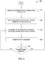
- Figure 5 illustrates a flow diagram of method steps for directing a user to modify an aspect of a vehicle via haptic output, according to various embodiments.
- the method steps are described in conjunction with the system of Figures 1-3 and 4A-4C , persons skilled in the art will understand that any system configured to perform the method steps, in any order, falls within the scope of the present invention.
- a method 500 begins at step 510, where haptic guidance application 132 receives one or more control signals from a control unit.
- haptic guidance application 132 may also determine a parameter that should be modified and a vehicle device that is associated with the parameter.
- haptic guidance application 132 selects one or more haptic output devices located proximate to the vehicle device.
- haptic guidance application 132 determines a haptic sensation to generate via the one or more haptic output devices.
- haptic guidance application 132 generates a haptic sensation on the user.
- haptic guidance application 132 determines whether the parameter has been modified (e.g. , by the user). For example, at step 550, haptic guidance application 132 could be notified by a control unit that the parameter has changed. Alternatively or additionally, haptic guidance application 132 may determine that the parameter has been modified by analyzing sensor data which indicates that the position of the vehicle device has changed.
- step 550 haptic guidance application 132 determines that the parameter has changed
- method 500 returns to step 510, where haptic guidance application 132 receives one or more control signals from a control unit. If the parameter has not changed, then method 500 returns to step 530, where haptic guidance application 132 may again determine a haptic sensation to generate on the driver via one or more haptic output devices.
- haptic guidance application 132 may determine that the position and/or orientation of the user (e.g. , the user's hand) has changed. In such embodiments, if the parameter has not changed, then method 500 returns to step 520, where haptic guidance application 132 selects one or more haptic output devices proximate to a vehicle device. Haptic guidance application 132 selects haptic output devices proximate to the vehicle device which can direct haptic output to the new location and/or orientation of the user's hand.
- haptic sensations may be generated on any part of a user's body. In various embodiments, the haptic output devices generate haptic sensations on the user without making any type of direct, physical contact with the user.
- haptic guidance application 132 may determine the position of the user via sensor data from one or more sensors. Haptic guidance application 132 may further receive the size and orientation of the driver's hand, in addition to the position and orientation of the hand relative to the vehicle device. Further, in some embodiments, at step 520, haptic guidance application 132 may determine which haptic output devices are proximate to the vehicle device and may select one or more haptic output devices to generate a haptic sensation on the user. Then, at step 530, haptic guidance application 132 could determine one or more characteristics of the haptic sensation to generate on the user. For example, haptic guidance application 132 could determine the size, shape, location, and intensity of the haptic sensation.
- haptic guidance application 132 could determine the direction, frequency and movement that the haptic sensation should have on the user's hand.
- Haptic guidance application 132 may determine one or more characteristics of the haptic sensation based on the type, position, and/or orientation of the haptic output devices which are proximate to the vehicle device and the position and orientation of the vehicle device and the user.
- the haptic guidance application receives a control signal from a control unit.
- the haptic guidance application may then determine a parameter that should be modified and a vehicle device that is associated with the parameter.
- the haptic guidance application may then select one or more haptic output devices proximate to the vehicle device and also determine a haptic sensation to generate on the user.
- the haptic guidance application then transmits a control signal to the haptic output device(s), which generate a haptic sensation on the user.
- At least one advantage of the techniques described herein is that a user can be notified that a parameter should be modified without requiring the user to divert his or her attention to a visual and/or auditory notification. Accordingly, a user is able to determine the parameter(s) which should be modified without the user having to expend additional cognitive resources to analyze a visual and/or auditory notification. Further, haptic sensations can be implemented as an alternative means for communicating various types of information to the user without overwhelming the user's visual and auditory senses. As a result, the techniques described herein may reduce the cognitive workload placed on a user when various types of information are provided to the user.
- aspects of the present embodiments may be embodied as a system, method or computer program product. Accordingly, aspects of the present disclosure may take the form of an entirely hardware embodiment, an entirely software embodiment (including firmware, resident software, micro-code, etc.) or an embodiment combining software and hardware aspects that may all generally be referred to herein as a "circuit,” “module” or “system.” Furthermore, aspects of the present disclosure may take the form of a computer program product embodied in one or more computer readable medium(s) having computer readable program code embodied thereon.
- the computer readable medium may be a computer readable signal medium or a computer readable storage medium.
- a computer readable storage medium may be, for example, but not limited to, an electronic, magnetic, optical, electromagnetic, infrared, or semiconductor system, apparatus, or device, or any suitable combination of the foregoing.
- a computer readable storage medium may be any tangible medium that can contain, or store a program for use by or in connection with an instruction execution system, apparatus, or device.
- each block in the flowchart or block diagrams may represent a module, segment, or portion of code, which comprises one or more executable instructions for implementing the specified logical function(s).
- the functions noted in the block may occur out of the order noted in the figures. For example, two blocks shown in succession may, in fact, be executed substantially concurrently, or the blocks may sometimes be executed in the reverse order, depending upon the functionality involved.
Description
- This application claims benefit of
United States provisional patent application serial number 62/365,960, filed July 22, 2016 - The various embodiments relate generally to human-machine interfaces and, more specifically, to a haptic driving guidance system.
- Modern vehicles, such as automobiles, motorbikes, boats, and airplanes, increasingly rely on control units to monitor and optimize the performance of vehicle subsystems. For example, a control unit could determine that a particular subsystem is performing suboptimally and then determine one or more parameters that could be adjusted in order to improve the operation of the subsystem. Some parameters, on the other hand, can be adjusted directly by the driver. For example, a driver may operate one or more vehicle devices, such as a transmission clutch and a gearshift, in order to disengage a vehicle drive shaft and then adjust a transmission gear ratio.
- Conventionally, when a driver is operating a particular vehicle subsystem in a suboptimal manner, a control unit may activate a visual and/or auditory notification to indicate to the driver that one or more parameters associated with the subsystem should be adjusted. For example, when a vehicle transmission is in a suboptimal gear, an up-arrow may be displayed on a car dashboard display, indicating that the driver should shift to a higher gear, or a down-arrow may be displayed, indicating that the driver should shift to a lower gear. In addition, conventional systems may generate an alert tone to indicate that the driver should shift gears. Document
US 2015/0197283 A discloses a system for communicating navigation information to a vehicle operator through actuators in a steering mechanism for a vehicle. The steering mechanism includes multiple actuators along or in a surface a vehicle operator touches to steer the vehicle. Different numbers of actuators can be actuated under an operator's hand to communicate the severity of an upcoming turn. Alternatively, an actuator can be actuated by different amounts to communicate the severity of an upcoming turn. Proximity of an upcoming turn can be communicated by cycling actuators at different rates for different turns. By actuating actuators under an operator's left hand or the left portion of a hand, a left-hand turn can be communicated. Conversely, by actuating actuators under an operator's right hand or the right portion of a hand, a right-hand turn can be communicated. - These types of conventional approaches may require the driver to direct his or her attention towards interpreting visual and/or auditory notification(s). For example, visual and/or auditory notifications may not clearly indicate to the driver which action(s) should be taken in a given situation. As a result, a driver may be required to expend additional cognitive resources in order to interpret the visual and auditory notifications.
- As the foregoing illustrates, techniques for more effectively providing driving guidance to a user would be useful.
- Embodiments of the present disclosure set forth a method for directing a user to modify an aspect of a vehicle via haptic output. The method includes determining, based on a first control signal received from a vehicle control unit, that a parameter associated with a vehicle device should be modified, determining, based on a current value for the parameter and a target value for the parameter, an initial position of the haptic output and a path to move the haptic output on a hand or an arm of the user, and generating the control signal based on the initial position and the path. The method further includes transmitting one or more second control signals to one or more haptic output devices that are proximate to the vehicle device, where the one or more haptic output devices generate haptic output based on the one or more second control signals.
- Further embodiments provide, among other things, a system and a non-transitory computer-readable storage medium configured to implement the techniques set forth above.
- At least one advantage of the techniques described herein is that a user can be notified that a parameter should be modified without requiring the user to divert his or her attention to a visual and/or auditory notification. Accordingly, a user is able to determine the parameter(s) which should be modified without the user having to expend additional cognitive resources to analyze a visual and/or auditory notification. Further, haptic sensations can be implemented as an alternative means for communicating various types of information to the user without overwhelming the user's visual and auditory senses. As a result, the techniques described herein may reduce the cognitive workload placed on a user when various types of information are provided to the user.
- So that the manner in which the recited features of the one or more embodiments set forth above can be understood in detail, a more particular description of the one or more embodiments, briefly summarized above, may be had by reference to certain specific embodiments, some of which are illustrated in the appended drawings. It is to be noted, however, that the appended drawings illustrate only typical embodiments and are therefore not to be considered limiting of its scope in any manner, for the scope of the various embodiments subsumes other embodiments as well.
-
Figure 1 illustrates a conceptual block diagram of a computing device configured to implement one or more aspects of the present invention, according to various embodiments; -
Figure 2 illustrates a technique for directing a driver to shift the position of a vehicle gearshift via haptic sensations, according to various embodiments; -
Figure 3 illustrates a technique for guiding steering behavior via haptic sensations, according to various embodiments; -
Figures 4A-4C illustrate different arrangements of haptic output devices for generating haptic sensations, according to various embodiments; and -
Figure 5 illustrates a flow diagram of method steps for directing a user to modify an aspect of a vehicle via haptic output, according to various embodiments. -
Figure 1 illustrates a conceptual block diagram ofcomputing device 100 configured to implement one or more aspects of the present invention, according to various embodiments. As shown,computing device 100 includes, without limitation,processing unit 110, input/output (I/O)devices 120, andmemory device 130.Memory device 130 includes ahaptic guidance application 132 configured to interact withdatabase 134. -
Processing unit 110 may include a central processing unit (CPU), digital signal processing unit (DSP), a sensor processing unit, a controller unit, and so forth. In various embodiments,processing unit 110 is configured to analyze sensor data acquired via one or more sensors to determine a position and/or orientation of one or more parts of a user (e.g., a user's hand, finger, wrist, arm, foot, ankle, leg, trunk, etc.) and/or determine a position and/or orientation of a vehicle device. In some embodiments,processing unit 110 is further configured to determine the position and/or orientation of the vehicle device relative to a position and/or orientation of the user. For example, and without limitation,processing unit 110 could executehaptic guidance application 132 to analyze sensor data and/or data from one or more control units in order to determine that a hand and/or a vehicle device are in a particular position and/or orientation. In addition,processing unit 110 may continually process sensor data and data from one or more control units as the position and/or orientation of the hand and/or the vehicle device change. - I/
O devices 120 may include input devices, output devices, and devices capable of both receiving input and providing output. For example, and without limitation, I/O devices 120 may include external cameras, driver facing cameras, global navigation satellite systems (GNSS) speedometer, tachometer, telemetry sensors, external network connections, gyroscopes, barometers, fuel-level sensors, tire pressure sensors, etc. I/O devices 120 may also include one or more haptic output devices, such as ultrasound transducers, air vortex generators, pneumatic devices, air bladders, etc. In addition, I/O devices 120 may include surface changing devices, such as a device that uses microfluidics, ferrofluidics, electrostatic, and/or electrodynamic methods to change the characteristics of a vehicle surface. Moreover, I/O devices may also include wearable haptic transducers on a forearm, leg, finger, etc. I/O devices could include one or more wired or wireless communication devices that receive sensor data including a position and/or orientation of a vehicle device, a position and/or orientation of a user, in addition to interaction events between the vehicle device and the user (e.g., via a controller area network, a local interconnect network, a FlexRay®, etc.). -
Memory unit 130 may include a memory module or collection of memory modules.Memory unit 130 includeshaptic guidance application 132 anddatabase 134.Haptic guidance application 132 may receive data from I/O devices 120 and/oraccess database 134.Database 134 may store digital signal processing algorithms, object recognition data, and user preferences data.Processing unit 110 executeshaptic guidance application 132, thereby implementing some or all functions ofcomputing device 100. -
Computing device 100 as a whole may be a microprocessor, an application-specific integrated circuit (ASIC), a system-on-a-chip (SoC) and so forth. Generally,computing device 100 may be configured to coordinate the overall operation of a haptic output device, such as an ultrasonic transducer array, an air vortex generator, etc. In other embodiments,computing device 100 may be coupled to, but separate from one or more haptic output devices. In such embodiments, the haptic output devices may include a dedicated processor that receives data (e.g., a position and/or orientation of a hand and a vehicle device) fromcomputing device 100 and transmits data (e.g., haptic output event data) to computingdevice 100. In some embodiments, the dedicated processor may be included in a driver assistance system or may be physically brought into an environment by the user as a mobile or wearable device. The mobile or wearable device may be physically or wirelessly connected tocomputing device 100. For example, the dedicated processor could be included in a consumer electronic device, such as a smartphone, personal computer, wearable device and the like. However, the embodiments disclosed herein contemplate any technically feasible system configured to implement the functionality of the haptic output devices. - As noted above, conventional approaches may require the driver to direct his or her attention towards interpreting visual and/or auditory notification(s). For example, visual and/or auditory notifications may not clearly indicate to the driver which action(s) should be taken in a given situation. As a result, a driver may be required to expend additional cognitive resources in order to interpret the visual and auditory notifications.
- Various embodiments described herein provide techniques for driver guidance beyond the conventional approaches by generating one or more haptic sensations that indicate one or more actions that should be performed by a user (e.g., a driver) in order to modify one or more vehicle parameters. For example, the driver could modify one or more parameters by changing a position and/or state of one or more vehicle devices. In general, the vehicle may include any type of transportation device, including, without limitation, a car, a truck, a motorbike, a boat, a submarine, a personal watercraft, a snow mobile, an airplane, a space craft, and so forth. The driver could be located inside the vehicle or outside of the vehicle, such as in a remote drone control station. In operation,
haptic guidance application 132 receives a notification of the parameter(s) which should be modified. In some embodiments,haptic guidance application 132 could then determine the location of the user (e.g., the user's hand, arm, foot, ankle, finger, finger tip, and so forth), such as the location of the user relative to a vehicle device that corresponds to the parameter(s). Next,haptic guidance application 132 may determine a type of haptic sensation to generate on the user. For example,haptic guidance application 132 could determine the frequency, intensity, location, size, movement, pattern, direction, shape, etc. of a haptic sensation to be generated on the user. Finally,haptic guidance application 132 generates the haptic sensation on the user via one or more haptic output devices in order to direct the user to modify the vehicle parameter(s). In particular, haptic output devices that generate haptic sensations on a user without making direct, physical contact with the user can be implemented in any embodiment disclosed herein. Examples of such techniques are described below in further detail in conjunction withFigures 2 ,3 ,4A-4C , and5 . -
Figure 2 illustrates a technique for directing a driver to shift the position of a vehicle gearshift via haptic sensations, according to various embodiments. As shown,system environment 200 includesgearshift knob 210,gearshift plate 220,sensors 230, andhaptic output devices 240. In general,haptic output devices 240 may include any type of device, such as an ultrasonic transducer array and/or an air output device, that is capable of generating a haptic sensation on a user. - As noted above, in various embodiments, haptic sensations may be generated in order to direct a driver to operate a vehicle device (e.g., gearshift knob 210) to modify one or more parameters of the vehicle. In some embodiments,
haptic guidance application 132 receives control signals from one or more control units included in the vehicle via one or more communications pathways (e.g., a vehicle bus, a controller area network, a local interconnect network, a wireless communications protocol, etc.). For example, a control unit could transmit one or more signals tohaptic guidance application 132 in order to indicate that a vehicle parameter should be modified by a user.Haptic guidance application 132 then generates haptic output 250 to indicate to the user that the vehicle parameter should be modified and/or how the vehicle parameter should be modified. - For example, as shown in
Figure 2 , haptic sensations could be generated on a hand of a driver viahaptic output devices 240 to direct the driver to upshift or downshift a vehicle transmission via thegearshift knob 210. In some embodiments, an engine control unit could first notifyhaptic guidance application 132 via a vehicle bus that the transmission should be upshifted or downshifted.Haptic guidance application 132 could then generate haptic output 250 via thehaptic output devices 240 to indicate to the driver that the position of thegearshift knob 210 should be changed in order to modify the transmission and/or how the position of thegearshift knob 210 should be changed (e.g., by moving thegearshift knob 210 into a slot ofgearshift plate 220 that is associated with a higher or lower transmission gear). - In some embodiments, the haptic output 250 generated by the haptic output device(s) 240 indicates a specific direction that the user should move the vehicle device in order to modify a corresponding parameter. For example, as shown in
Figure 2 , haptic output 250 could be generated in a specific direction across the hand of a driver, where the direction indicates the gear to which the driver should move thegearshift knob 210. In a more specific example, if thegearshift knob 210 was in fifth gear, andhaptic guidance application 132 received a control signal indicating that the transmission should be downshifted, then haptic output 250-3 could be generated to instruct the driver to shift to fourth gear. In another example, if thegearshift knob 210 was in second gear andhaptic guidance application 132 received a control signal indicating that the transmission should be upshifted, then haptic output 250-1 could be generated to instruct to the driver to shift to third gear. Similar directional techniques may be implemented byhaptic guidance application 132 for any type of vehicle device that enables a parameter to be modified by pushing, pulling, sliding, or otherwise repositioning the vehicle device in a specific direction. - In one embodiment, the specific direction that the
haptic guidance application 132 indicates via haptic output is an absolute direction. In particular, the absolute direction may be the direction in which the hand should move in order to move the vehicle device to the new position. For example, haptic output 250-1 could indicate the direction that the driver should move his hand in order to move thegearshift knob 210 from the second gear slot to the third gear slot. Even when the orientation of the user's hand changes with respect to thegearshift knob 210, thehaptic guidance application 132 does not vary the direction of haptic output 250-1. Additionally or alternatively,haptic guidance application 132 may indicate a relative direction on the user's hand. When generating a relative direction,haptic guidance application 132 varies the direction of haptic output 250-1 with respect to the present orientation of the user's hand. Thus,haptic guidance application 132 configures the haptic output devices to generate haptic output that moves between two parts of the user's hand, regardless of how the hand is oriented with respect to the vehicle device. For example, regardless of how the user's hand is oriented with respect to thegearshift knob 210, thehaptic guidance application 132 could generate haptic output 250-1 that moves between the center of the user's hand and the knuckle of the pinky finger. Such a haptic sensation would consistently indicate that the user should shift thegearshift knob 210 from the second gear slot to the third gear slot. - In the only one embodiment falling under the scope of the present invention,
haptic guidance application 132 may generate haptic sensations that are perceived by a user as having a specific shape (e.g., a ridge). In addition,haptic guidance application 132 may determine an initial position and a path along which the haptic sensation should move on the user's hand. Specifically, the haptic sensation may first be generated at an initial position on the hand of the user and then moved along a path in one or more directions on the user's hand. For example,haptic guidance application 132 could generate a haptic sensation in the form of a ridge which starts at the wrist of the left hand and moves to the knuckles of the left hand.Haptic guidance application 132 could further generate another haptic sensation in the form of a ridge which starts at the knuckles of the right hand and moves to the wrist of the right hand. In some embodiments,haptic guidance application 132 may receive the current value of one or more parameter(s) and the target value of the parameter(s).Haptic guidance application 132 may then determine which vehicle device(s) are associated with the parameter(s) and the manner in which the vehicle device(s) should be modified in order to change the value of the parameter(s) from the current value to the target value. Additionally or alternatively, upon receiving an indication that a vehicle parameter should be modified,haptic guidance application 132 could select from a set of predetermined transitions (e.g., stored in database 134) that are associated with the vehicle device. For example, an engine control unit could indicate the current gear in which a transmission is operating and that the gear should be increased.Haptic guidance application 132 could then determine, based on a predetermined transition associated with shifting from second gear to third gear, that haptic output 250-1 should be generated on the user to direct the user to movegearshift knob 210 upwards and to the right.Haptic guidance application 132 could then causehaptic output devices 240 to generate haptic output 250-1 on the user. - In some embodiments,
haptic guidance application 132 may associate specific parameters with specific vehicle devices and/or haptic output devices 240 (e.g., via a look-up table stored in database 134). Then, upon receiving, from a control unit, a control signal that specifies a particular parameter,haptic guidance application 132 may determine a vehicle device that is associated with the parameter and/or one or morehaptic output devices 240 that should be implemented to generate the haptic sensations.Haptic guidance application 132 then causes those haptic output device(s) 240 to generate a haptic sensation on the user. - In some embodiments, a control unit may indicate to
haptic guidance application 132 the vehicle device(s) that are associated with one or more parameters that should be modified as well as the manner in which those vehicle device(s) should be modified. For example, a control unit could indicate tohaptic guidance application 132 that a clutch pedal should be depressed and/or how far the clutch pedal should be depressed before the position ofgearshift knob 210 is modified.Haptic guidance application 132 could then generate haptic output 250 via one or morehaptic output devices 240 proximate to the clutch pedal to direct the driver to depress the clutch pedal by the distance specified by the control unit. For example, haptic output 250 could be generated on a leg or foot of the user until the clutch pedal reaches the position specified by the control unit.Haptic guidance application 132 could implement similar techniques with respect to a vehicle accelerator pedal and/or a vehicle brake pedal. - In various embodiments, one or
more sensors 230 may be implemented to acquire sensor data that is then processed byhaptic guidance application 132 to determine the location and/or orientation of the user and/or a vehicle device. For example,haptic guidance application 132 could analyze sensor data acquired by the sensor(s) 230 to determine whether a hand of the driver is located proximate to one or more vehicle devices (e.g., gearshift knob 210).Haptic guidance application 132 could then cause one or morehaptic output devices 240 to generate haptic output 250 based on the specific location of the hand of the user. In some embodiments, by determining the specific location of the user and/or a vehicle device being operated by a user, haptic output 250 may be more precisely generated in order to direct the user to modify the vehicle device in a specific manner. For example, with reference toFigure 2 , different users may position their hand in different locations ongearshift knob 210. As a result, detecting the location of the hand of the user via one ormore sensors 230 may enable haptic output 250 to be generated more precisely on a specific portion of the hand. - Further,
guidance application 132 could analyze sensor data in order to determine the location of the user (e.g., a location of a hand, arm, foot, leg, etc.) in order to select one or morehaptic output devices 240 that are proximate to that location. Haptic output 250 could then be generated on the user via the selectedhaptic output devices 240. For example,haptic guidance application 132 could determine the location and orientation of the driver's hand with respect togearshift knob 210 by analyzing sensor data received fromsensors 230.Haptic guidance application 132 could then select one or morehaptic output devices 240 that are best positioned to generate haptic sensations on the hand. - In some embodiments,
haptic guidance application 132 may further determine a frequency, shape, orientation, position, and/or intensity of the haptic sensation. For example,haptic guidance application 132 could vary the frequency and intensity of the haptic sensation in order to convey to the driver the urgency of shifting the transmission to a different gear. -
Haptic output devices 240 may be located at various positions around the vehicle, such asabove gearshift knob 210, on the vehicle dashboard, below the driver's hand, etc. For example, insystem environment 200,haptic output devices 240 are located abovegearshift knob 210. Additionally,haptic output devices 240 can be opportunistically placed in unused areas of the vehicle (e.g., unused space on the vehicle dashboard) that provide an appropriate output trajectory relative to the vehicle device(s) and/or the driver. In addition,haptic output devices 240 can be proximate to a vehicle device (e.g., within a vehicle device, along a perimeter of the vehicle device) and/or proximate to the user. -
Figure 3 illustrates a technique for guiding steering behavior via haptic sensations, according to various embodiments. As shown,system environment 300 includessteering wheel 310,sensors 320, andhaptic output devices 330. - In various embodiments,
haptic guidance application 132 may direct a driver to modify his or her steering behavior via haptic sensations. For example,haptic guidance application 132 could receive one or more control signals from a control unit, where the control signals indicate that the car should be steered in a particular direction. One or morehaptic output devices 330 may then be implemented to generate haptic sensations on a user's hands to direct the user to move the steering wheel in a particular manner. For example, haptic sensations could be generated on the left hand of the user to direct the user to steer to the left, or haptic sensations could be generated on the right hand of the user to direct the user to steer to the right. Additionally, in some embodiments, haptic sensations could be generated in a specific direction across the hand and/or arm of the user to indicate that the steering wheel should be turned to the left or right. For example, haptic sensations could be generated in a clockwise direction across the user to indicate that the wheel should be turned to the right, or haptic sensations could be generated in a counterclockwise direction across the user to indicate that the wheel should be turned to the left. Similar techniques may be implemented byhaptic guidance application 132 for any type of vehicle device that enables a parameter to be modified by turning or rotating the vehicle device. -
Haptic guidance application 132 may further determine the location of the user relative to the vehicle device viasensors 320. In some embodiments,haptic guidance application 132 may analyze the sensor data fromsensors 320 to determine the direction thathaptic output devices 330 should output haptic output in order to generate a haptic sensation on the user's hands. Then,haptic guidance application 132 may further determine one or more characteristics of the haptic sensation to generate on the user and may output control signals tohaptic output devices 330 that generate the haptic sensation on the user. - For example, if the vehicle is drifting out of a lane and/or is moving towards the edge of the road,
haptic guidance application 132 could determine the orientation of the steering wheel and optionally determine the location and orientation of the driver's hands via one or more ofsensors 320.Haptic guidance application 132 could then determine one or more characteristics of the haptic sensation to generate on the driver's hand in order to indicate to the driver that he or she should steer the vehicle back into the lane and/or away from the edge of the road. In some embodiments, one or more haptic sensations that are perceived by the driver as ridges, described above, could be generated on the hand(s) of a driver to indicate that he or she should turn the steering wheel to the right or left. Additionally, the frequency and/or intensity of a haptic sensation may be increased as the driver drifts further towards a dangerous condition, such as when a vehicle drifts further towards the edge of a road, across a lane line, and/or towards another vehicle or object. - In some embodiments,
haptic guidance application 132 may guide the driver through some or all actions that the driver should take to drive a vehicle from one location to another location. For example,haptic guidance application 132 could generate sequences of haptic sensations in order to guide a driver in steering between his house and his place of work.Haptic guidance application 132 could further generate sequences of haptic sensations via one or morehaptic output devices 240 to guide the driver's shifting behavior, acceleration, braking, and so forth in order to facilitate the driver in safely traveling to a given destination. - For example,
haptic output devices 330 could be located on a vehicle steering column and/or in a vehicle foot well. Whenhaptic guidance application 132 receives control signals indicating that the vehicle should accelerate,haptic guidance application 132 could determine the location and orientation of the driver's feet via sensor data from one ormore sensors 320 located in the foot well. Then, ifhaptic guidance application 132 determines that the driver's foot is located over the accelerator,haptic guidance application 132 could determine one or more characteristics of a haptic sensation to generate on the driver's foot in order to indicate to the driver that he or she should depress the accelerator. If, on the other hand,haptic guidance application 132 determines that the foot is located over the brake, thenhaptic guidance application 132 could determine one or more characteristics of a haptic sensation to generate on the driver's foot to indicate to the driver that he or she should lift his or her foot from the brake pedal and move the foot onto the accelerator. For example,haptic guidance application 132 could generate a haptic sensation on the driver's foot viahaptic output devices 330, where the haptic sensation moves from the left side of the foot to the right side of the foot in order to indicate to the driver that he or she should move his foot from the brake pedal to the accelerator. Next,haptic guidance application 132 could transmit control signals tohaptic output devices 330 in order to generate a second haptic sensation on the driver's foot which indicates to the driver that he or she should depress the accelerator. - In addition,
haptic guidance application 132 may generate a haptic sensation on the driver in order to alert the driver about a vehicle event, road condition, etc. For example, when the driver is in a semi-autonomous driving environment and the driver's seat is facing to the rear of the vehicle,haptic guidance application 132 may provide an alert to the driver in the form of a haptic sensation when he or she should turn his or her seat around and/or take control of a particular vehicle device. In addition,haptic guidance application 132 may generate a sequence of haptic sensations in order to guide the driver in turning his or her seat to face the front of the vehicle in order to facilitate him or her in modifying the vehicle device. - Moreover, in semi-autonomous vehicles,
haptic guidance application 132 may receive control signals from one or more control devices and generate haptic sensations on the driver in order to alert the driver that modifying one or more parameters is unsafe. For example, if the driver attempts to shift the transmission to a gear which is unsafe at the present speed of the vehicle, thenhaptic guidance application 132 may receive a control signal to generate a haptic sensation on the driver.Haptic guidance application 132 could then generate a haptic sensation which has a high intensity on the driver's hand. By implementing a haptic sensation with a high intensity,haptic guidance application 132 could alert and/or deter the driver from shifting the transmission to an unsafe gear. - In addition, if a vehicle has a driver monitoring system,
haptic guidance application 132 may implement various notifications from the driver monitoring system via haptic sensation on the driver. For example,haptic guidance application 132 could receive control signals from the driver monitoring system which indicate that the driver should modify one or more parameters by changing the position of one or more vehicle devices.Haptic guidance application 132 could then generate haptic sensations on the driver in order to indicate to the driver how he or she should vary the position of the vehicle device(s) in order to modify the parameter(s). -
Figures 4A-4C illustrate different arrangements of haptic output devices for generating haptic sensations, according to various embodiments. As shown,system environment 400 containsvehicle device 410 andhaptic output devices 420. - As noted herein,
haptic output devices 420 may include ultrasonic transducers, air output devices, and/or other types of haptic output devices. In various embodiments,haptic guidance application 132 may determine one or more characteristics of the haptic sensation generated on the driver's hand, including the intensity, location, shape, frequency, movement, and size of the haptic sensation. - In such embodiments,
haptic guidance application 132 may generate a haptic sensation with a particular set of characteristics, by causing the haptic output of two or morehaptic output devices 420 to constructively and/or destructively interfere. For example, haptic output generated by two or morehaptic output devices 420 may occupy a particular location in space at a particular time, enabling the haptic output of each haptic output device to interfere constructively and/or destructively with the haptic output of one or more other haptic output devices. Constructive and/or destructive interference between haptic output generated by different haptic output devices may then produce a haptic sensation at the location at which the haptic output constructively interferes. Accordingly, in various embodiments,haptic guidance application 132 may cause the haptic output from a haptic output device to interfere with the haptic output of one or more other haptic output devices in order to generate a haptic sensation at a particular location. - Further, in various embodiments,
haptic guidance application 132 may modify the intensity and/or phase of the haptic output generated by each haptic output device in order to further control the intensity pattern generated by the haptic outputs. Using such techniques,haptic guidance application 132 may shift the location of intensity peaks, may increase or decrease the number of intensity peaks, and/or may adjust the shape and/or magnitude of one or more intensity peaks. As a result,haptic guidance application 132 may localize and/or modify various characteristics of the haptic sensation generated on the user. For example,haptic guidance application 132 could use such techniques to alter the intensity, size, location, and/or shape of the haptic sensation generated on the user's hand. - In addition, air output devices (e.g., air vortex generators) may be used to generate haptic sensations on a driver's hand. In various embodiments,
haptic guidance application 132 may usehaptic output devices 420 that include air output devices to implement any of the techniques described herein. For example, air output devices located proximate tovehicle device 410 could generate haptic sensations on a driver's hand, palm, forearm, etc. in order to indicate to the driver that he or she should modify the position ofvehicle device 410. In addition, each air output device may emit air vortices into multiple areas, such as by implementing pan-tilt actuation which enables air vortex generators to emit air vortices in different directions. In such embodiments,haptic guidance application 132 may generate haptic sensations with complex characteristics on various parts of the user. - As shown in
Figure 4A ,haptic output devices 420 may be arranged in an array proximate tovehicle device 410. For example,haptic output devices 420 could be arranged in a 5-by-2 array. In various embodiments, arrays of other dimensions and/or shapes may be implemented. For example, ultrasonic transducer arrays could be arranged in 4-by-4 arrays, 8-by-8 arrays, 16-by-16 arrays, etc. Further, althoughhaptic output devices 420 are illustrated as being in a specific position relative tovehicle device 410, in other embodiments,haptic output devices 420 may be positioned at any location proximate tovehicle device 410. - In
Figure 4B ,haptic output devices 420 are arranged around the circumference ofvehicle device 410. Although the embodiment shown inFigure 4B implements an elliptical configuration ofhaptic output devices 420, any other shape (e.g., circular, rectangular, polygonal, freeform, etc.) may be implemented in various embodiments. In such embodiments, a haptic sensation may be generated on the driver's palm and/or forearm. In addition, haptic sensations may be generated on the driver's fingers and/or finger tips. - In
Figure 4C ,haptic output devices 420 are arranged onvehicle device 410. In such embodiments, haptic sensations could be generated on the driver's palm, fingers, and/or forearm. Additionally or alternatively, haptic output devices could be arranged sporadically aroundvehicle device 410. In some embodiments,haptic output devices 420 may be located in various areas of a vehicle with usable space (e.g., on surfaces of the vehicle with no vehicle devices, objects, or other obstructions, such as displays). Then, given a particular arrangement ofhaptic output devices 420 proximate tovehicle device 410,haptic guidance application 132 may control the haptic output of each ofhaptic output devices 420 in order to generate a haptic sensation on the driver's hand. - Although various embodiments disclosed herein are described with respect to specific types of vehicle devices, any of the techniques disclosed herein may be performed with respect to any type of vehicle device. Further, although various embodiments are described in conjunction with specific arrangements of haptic output devices, any of the arrangements of haptic output devices disclosed herein, such as those described above with respect to
Figures 4A-4C , may be implemented in any technique to generate haptic output proximate to any type of vehicle device. In addition, any arrangement ofhaptic output devices 420 may be implemented to generate haptic sensations having any shape, including, without limitation, haptic sensations having elliptical, rectangular, polygonal, and freeform shapes. -
Figure 5 illustrates a flow diagram of method steps for directing a user to modify an aspect of a vehicle via haptic output, according to various embodiments. Although the method steps are described in conjunction with the system ofFigures 1-3 and4A-4C , persons skilled in the art will understand that any system configured to perform the method steps, in any order, falls within the scope of the present invention. - As shown in
Figure 5 , amethod 500 begins atstep 510, wherehaptic guidance application 132 receives one or more control signals from a control unit. In some embodiments, atstep 510,haptic guidance application 132 may also determine a parameter that should be modified and a vehicle device that is associated with the parameter. Then, atstep 520,haptic guidance application 132 selects one or more haptic output devices located proximate to the vehicle device. Then, atstep 530,haptic guidance application 132 determines a haptic sensation to generate via the one or more haptic output devices. - Next, at
step 540,haptic guidance application 132 generates a haptic sensation on the user. Finally, atstep 550,haptic guidance application 132 determines whether the parameter has been modified (e.g., by the user). For example, atstep 550,haptic guidance application 132 could be notified by a control unit that the parameter has changed. Alternatively or additionally,haptic guidance application 132 may determine that the parameter has been modified by analyzing sensor data which indicates that the position of the vehicle device has changed. - If, at
step 550,haptic guidance application 132 determines that the parameter has changed, thenmethod 500 returns to step 510, wherehaptic guidance application 132 receives one or more control signals from a control unit. If the parameter has not changed, thenmethod 500 returns to step 530, wherehaptic guidance application 132 may again determine a haptic sensation to generate on the driver via one or more haptic output devices. - In some embodiments,
haptic guidance application 132 may determine that the position and/or orientation of the user (e.g., the user's hand) has changed. In such embodiments, if the parameter has not changed, thenmethod 500 returns to step 520, wherehaptic guidance application 132 selects one or more haptic output devices proximate to a vehicle device.Haptic guidance application 132 selects haptic output devices proximate to the vehicle device which can direct haptic output to the new location and/or orientation of the user's hand. Although various embodiments are described as generating haptic sensations on a hand of a user, in any of the embodiments described above, haptic sensations may be generated on any part of a user's body. In various embodiments, the haptic output devices generate haptic sensations on the user without making any type of direct, physical contact with the user. - In various embodiments, at
step 510,haptic guidance application 132 may determine the position of the user via sensor data from one or more sensors.Haptic guidance application 132 may further receive the size and orientation of the driver's hand, in addition to the position and orientation of the hand relative to the vehicle device. Further, in some embodiments, atstep 520,haptic guidance application 132 may determine which haptic output devices are proximate to the vehicle device and may select one or more haptic output devices to generate a haptic sensation on the user. Then, atstep 530,haptic guidance application 132 could determine one or more characteristics of the haptic sensation to generate on the user. For example,haptic guidance application 132 could determine the size, shape, location, and intensity of the haptic sensation. In addition,haptic guidance application 132 could determine the direction, frequency and movement that the haptic sensation should have on the user's hand.Haptic guidance application 132 may determine one or more characteristics of the haptic sensation based on the type, position, and/or orientation of the haptic output devices which are proximate to the vehicle device and the position and orientation of the vehicle device and the user. - In sum, the haptic guidance application receives a control signal from a control unit. The haptic guidance application may then determine a parameter that should be modified and a vehicle device that is associated with the parameter. The haptic guidance application may then select one or more haptic output devices proximate to the vehicle device and also determine a haptic sensation to generate on the user. The haptic guidance application then transmits a control signal to the haptic output device(s), which generate a haptic sensation on the user.
- At least one advantage of the techniques described herein is that a user can be notified that a parameter should be modified without requiring the user to divert his or her attention to a visual and/or auditory notification. Accordingly, a user is able to determine the parameter(s) which should be modified without the user having to expend additional cognitive resources to analyze a visual and/or auditory notification. Further, haptic sensations can be implemented as an alternative means for communicating various types of information to the user without overwhelming the user's visual and auditory senses. As a result, the techniques described herein may reduce the cognitive workload placed on a user when various types of information are provided to the user.
- The descriptions of the various embodiments have been presented for purposes of illustration, but are not intended to be exhaustive or limited to the embodiments disclosed. Many modifications and variations will be apparent to those of ordinary skill in the art without departing from the scope of the described embodiments.
- Aspects of the present embodiments may be embodied as a system, method or computer program product. Accordingly, aspects of the present disclosure may take the form of an entirely hardware embodiment, an entirely software embodiment (including firmware, resident software, micro-code, etc.) or an embodiment combining software and hardware aspects that may all generally be referred to herein as a "circuit," "module" or "system." Furthermore, aspects of the present disclosure may take the form of a computer program product embodied in one or more computer readable medium(s) having computer readable program code embodied thereon.
- Any combination of one or more computer readable medium(s) may be utilized. The computer readable medium may be a computer readable signal medium or a computer readable storage medium. A computer readable storage medium may be, for example, but not limited to, an electronic, magnetic, optical, electromagnetic, infrared, or semiconductor system, apparatus, or device, or any suitable combination of the foregoing. More specific examples (a non-exhaustive list) of the computer readable storage medium would include the following: an electrical connection having one or more wires, a portable computer diskette, a hard disk, a random access memory (RAM), a read-only memory (ROM), an erasable programmable read-only memory (EPROM or Flash memory), an optical fiber, a portable compact disc read-only memory (CD-ROM), an optical storage device, a magnetic storage device, or any suitable combination of the foregoing. In the context of this document, a computer readable storage medium may be any tangible medium that can contain, or store a program for use by or in connection with an instruction execution system, apparatus, or device.
- Aspects of the present disclosure are described above with reference to flowchart illustrations and/or block diagrams of methods, apparatus (systems) and computer program products according to embodiments of the disclosure. It will be understood that each block of the flowchart illustrations and/or block diagrams, and combinations of blocks in the flowchart illustrations and/or block diagrams, can be implemented by computer program instructions. These computer program instructions may be provided to a processor of a general purpose computer, special purpose computer, or other programmable data processing apparatus to produce a machine, such that the instructions, which execute via the processor of the computer or other programmable data processing apparatus, enable the implementation of the functions/acts specified in the flowchart and/or block diagram block or blocks. Such processors may be, without limitation, general purpose processors, special-purpose processors, application-specific processors, or field-programmable processors or gate arrays.
- The flowchart and block diagrams in the figures illustrate the architecture, functionality, and operation of possible implementations of systems, methods and computer program products according to various embodiments of the present disclosure. In this regard, each block in the flowchart or block diagrams may represent a module, segment, or portion of code, which comprises one or more executable instructions for implementing the specified logical function(s). It should also be noted that, in some alternative implementations, the functions noted in the block may occur out of the order noted in the figures. For example, two blocks shown in succession may, in fact, be executed substantially concurrently, or the blocks may sometimes be executed in the reverse order, depending upon the functionality involved. It will also be noted that each block of the block diagrams and/or flowchart illustration, and combinations of blocks in the block diagrams and/or flowchart illustration, can be implemented by special purpose hardware-based systems that perform the specified functions or acts, or combinations of special purpose hardware and computer instructions.
- While the preceding is directed to embodiments of the present disclosure, other and further embodiments of the disclosure may be devised without departing from the basic scope thereof, and the scope thereof is determined by the claims that follow.
Claims (14)
- A system (200) for directing a user to modify an aspect of a vehicle via haptic output, the system (200) comprising:one or more haptic output devices (240) configured to generate haptic output in response to a control signal; anda processor coupled to the one or more haptic output devices (240) and configured to:determine, based on a second control signal received from a vehicle control unit that a parameter associated with a vehicle device should be modified;determine, based on a current value for the parameter and a target value for the parameter, an initial position of the haptic output and a path to move the haptic output on a hand or an arm of the user;generate the control signal based on the initial position and the path; andtransmit the control signal to the one or more haptic output devices (240).
- The system (200) of claim 1, wherein the haptic output indicates at least one of a direction in which the vehicle device should be moved and a distance by which the vehicle device should be moved.
- The system (200) of claim 1, wherein the second control signal comprises the target value of the parameter.
- The system (200) of claim 3, wherein the processor is further configured to:determine, based on a current value of the parameter and the target value of the parameter, at least one of a direction and a location of the haptic output generated by the one or more haptic output devices (240); andgenerate the control signal based on the at least one of the direction and the location.
- The system (200) of claim 3, wherein the processor is further configured to select, based on a current value of the parameter and the target value of the parameter, the one or more haptic output devices (240) from a plurality of haptic output devices (240).
- The system (200) of claim 1, further comprising one or more sensors (230) coupled to the processor and configured to acquire sensor data, wherein the processor is further configured to analyze the sensor data to determine a location of a user.
- The system (200) of claim 6, wherein the processor is further configured to determine, based on the location of the user, at least one of a direction and a location of the haptic output generated by the one or more haptic output devices (240).
- The system (200) of claim 6, wherein the processor is further configured to select, based on the location of the user, the one or more haptic output devices (240) from a plurality of haptic output devices (240).
- The system (200) of claim 1, wherein the one or more haptic output devices (240) comprise at least one of an ultrasound transducer and an air output device.
- The system (200) of claim 1, wherein the haptic output comprises a ridge, and the one or more haptic output devices (240) are configured to change a location of the ridge as a function of time to indicate a direction in which the vehicle device should be moved.
- The system (200) of claim 1, wherein generating the haptic output comprises generating first haptic output via a first haptic output device included in the one or more haptic output devices (240), and generating second haptic output via a second haptic output device included in the one or more haptic output devices (240), wherein the first haptic output constructively interferes with the second haptic output proximate to the vehicle device.
- The system (200) of claim 1, wherein the vehicle device comprises at least one of a gearshift device, a steering device, an accelerator device, a braking device, and a clutch device.
- A method for directing a user to modify an aspect of a vehicle via haptic output, the method comprising:determining, based on a first control signal received from a vehicle control unit, that a parameter associated with a vehicle device should be modified;determining, based on a current value for the parameter and a target value for the parameter, an initial position of the haptic output and a path to move the haptic output on a hand or an arm of the user; generating a one or more second control signals based on the initial position and the path; andtransmitting the one or more second control signals to one or more haptic output devices (240) that are proximate to the vehicle device, wherein the one or more haptic output devices (240) generate haptic output based on the one or more second control signals.
- A computer program product comprising instructions which, when the program is executed by a computer, cause the computer to direct a user to modify an aspect of a vehicle via haptic output, by performing the steps of:determining, based on a first control signal received from a vehicle control unit, that a parameter associated with a vehicle device should be modified;determining, based on a current value for the parameter and a target value for the parameter, an initial position of the haptic output and a path to move the haptic output on a hand or an arm of the user;generating a one or more second control signals based on the initial position and the path; andin response to the determining, transmitting the one or more second control signals to one or more haptic output devices (240) that are proximate to the vehicle device, wherein the one or more haptic output devices (240) generate haptic output based on the one or more second control signals.
Applications Claiming Priority (2)
| Application Number | Priority Date | Filing Date | Title |
|---|---|---|---|
| US201662365960P | 2016-07-22 | 2016-07-22 | |
| PCT/US2017/037619 WO2018017212A1 (en) | 2016-07-22 | 2017-06-15 | Haptic driving guidance system |
Publications (3)
| Publication Number | Publication Date |
|---|---|
| EP3487280A1 EP3487280A1 (en) | 2019-05-29 |
| EP3487280A4 EP3487280A4 (en) | 2019-12-25 |
| EP3487280B1 true EP3487280B1 (en) | 2022-03-30 |
Family
ID=60992731
Family Applications (6)
| Application Number | Title | Priority Date | Filing Date |
|---|---|---|---|
| EP17831480.3A Active EP3487280B1 (en) | 2016-07-22 | 2017-06-15 | Haptic driving guidance system |
| EP17831478.7A Active EP3488427B1 (en) | 2016-07-22 | 2017-06-15 | Haptic guidance system |
| EP17831937.2A Active EP3488184B1 (en) | 2016-07-22 | 2017-07-21 | Echolocation with haptic transducer devices |
| EP17831938.0A Active EP3488325B1 (en) | 2016-07-22 | 2017-07-21 | Haptic system for delivering audio content to a user |
| EP17831936.4A Active EP3487739B1 (en) | 2016-07-22 | 2017-07-21 | Haptic notification system for vehicles |
| EP17831989.3A Active EP3488326B1 (en) | 2016-07-22 | 2017-07-21 | Haptic system for actuating materials |
Family Applications After (5)
| Application Number | Title | Priority Date | Filing Date |
|---|---|---|---|
| EP17831478.7A Active EP3488427B1 (en) | 2016-07-22 | 2017-06-15 | Haptic guidance system |
| EP17831937.2A Active EP3488184B1 (en) | 2016-07-22 | 2017-07-21 | Echolocation with haptic transducer devices |
| EP17831938.0A Active EP3488325B1 (en) | 2016-07-22 | 2017-07-21 | Haptic system for delivering audio content to a user |
| EP17831936.4A Active EP3487739B1 (en) | 2016-07-22 | 2017-07-21 | Haptic notification system for vehicles |
| EP17831989.3A Active EP3488326B1 (en) | 2016-07-22 | 2017-07-21 | Haptic system for actuating materials |
Country Status (5)
| Country | Link |
|---|---|
| US (6) | US10671170B2 (en) |
| EP (6) | EP3487280B1 (en) |
| JP (7) | JP6992045B2 (en) |
| CN (6) | CN109475079B (en) |
| WO (6) | WO2018017212A1 (en) |
Families Citing this family (38)
| Publication number | Priority date | Publication date | Assignee | Title |
|---|---|---|---|---|
| WO2018047604A1 (en) * | 2016-09-12 | 2018-03-15 | ソニー株式会社 | Information presentation device, steering device, and information presentation method |
| DK179978B1 (en) * | 2016-09-23 | 2019-11-27 | Apple Inc. | Image data for enhanced user interactions |
| US10275083B2 (en) | 2017-09-20 | 2019-04-30 | Alex Hamid Mani | Assistive device with a refreshable haptic feedback interface |
| US11513627B2 (en) | 2017-09-20 | 2022-11-29 | Niki Mani | Assistive device with a refreshable haptic feedback interface |
| US11561619B2 (en) | 2017-09-20 | 2023-01-24 | Niki Mani | Haptic feedback device and method for providing haptic sensation based on video |
| US10281983B2 (en) | 2017-09-20 | 2019-05-07 | Alex Hamid Mani | Haptic feedback device and method for providing haptic sensation based on video |
| US11726571B2 (en) | 2017-09-20 | 2023-08-15 | Niki Mani | Assistive device for non-visually discerning a three-dimensional (3D) real-world area surrounding a user |
| WO2019185243A1 (en) * | 2018-03-26 | 2019-10-03 | Sony Corporation | Methods and apparatuses for proximity detection |
| US11009954B2 (en) | 2018-06-02 | 2021-05-18 | Harman International Industries, Incorporated | Haptics device for producing directional sound and haptic sensations |
| CN108919277B (en) * | 2018-07-02 | 2022-11-22 | 深圳米唐科技有限公司 | Indoor and outdoor environment identification method and system based on sub-ultrasonic waves and storage medium |
| CN109254652A (en) * | 2018-08-13 | 2019-01-22 | 瑞声科技(新加坡)有限公司 | Tactile feedback method, system and the control device of Vehicle touch display screen |
| CN109254658A (en) * | 2018-08-29 | 2019-01-22 | 上海天马微电子有限公司 | Tactile feedback method, haptic feedback devices and touch display unit |
| US11760377B2 (en) * | 2019-02-26 | 2023-09-19 | Harman International Industries, Incorporated | Shape-shifting control surface for an autonomous vehicle |
| JP7333185B2 (en) * | 2019-03-27 | 2023-08-24 | 株式会社Subaru | vehicle approach warning device |
| US11067687B2 (en) | 2019-04-25 | 2021-07-20 | Elwha, Llc | Multipath acoustic holography and virtual haptics |
| CN110347249B (en) * | 2019-06-25 | 2020-08-28 | 燕山大学 | Vibration mode superposition-based tactile feedback method |
| US10916107B1 (en) * | 2019-07-29 | 2021-02-09 | Elwha Llc | Time-domain and frequency-domain enhancements for acoustic haptography |
| US11100801B2 (en) | 2019-08-12 | 2021-08-24 | Toyota Motor North America, Inc. | Utilizing sensors to detect hazard from other vehicle while driving |
| US10962562B2 (en) * | 2019-08-22 | 2021-03-30 | Bayerische Motoren Werke Aktiengesellschaft | Vehicle velocity indicator |
| JP7406328B2 (en) | 2019-09-10 | 2023-12-27 | 株式会社東海理化電機製作所 | Control device, control method, and program |
| JP7282639B2 (en) * | 2019-09-10 | 2023-05-29 | 株式会社東海理化電機製作所 | Control device, control method and program |
| US11282281B2 (en) * | 2019-11-13 | 2022-03-22 | At&T Intellectual Property I, L.P. | Activation of extended reality actuators based on content analysis |
| CN111158465A (en) * | 2019-12-09 | 2020-05-15 | 瑞声科技(新加坡)有限公司 | Force touch vibration feedback method and system |
| CN110972020B (en) * | 2019-12-19 | 2021-06-01 | 东莞市逸音电子科技有限公司 | Novel intelligent touch Bluetooth headset |
| CN111338468B (en) * | 2020-02-05 | 2022-01-28 | 吉林大学 | Mobile terminal touch target operating system and method based on cross paradigm |
| KR20210112633A (en) * | 2020-03-05 | 2021-09-15 | 현대자동차주식회사 | Personal mobility and control method for the same |
| US11535260B2 (en) * | 2020-03-05 | 2022-12-27 | Harman International Industries, Incorporated | Attention-based notifications |
| US11703881B2 (en) * | 2020-03-19 | 2023-07-18 | Logistics And Supply Chain Multi Tech R&D Centre Limited | Method of controlling a guide machine and a navigation system |
| US20210319656A1 (en) * | 2020-04-10 | 2021-10-14 | Igt | Real-time analytics and feedback for electronic gaming machines |
| JP7072744B2 (en) * | 2020-05-13 | 2022-05-20 | 三菱電機株式会社 | Aerial haptics controller, aerial haptics system and aerial haptics control method |
| KR102591674B1 (en) * | 2020-07-10 | 2023-10-23 | 한국전자통신연구원 | Devices for playing acoustic sound and touch sensation |
| GB2597492B (en) * | 2020-07-23 | 2022-08-03 | Nissan Motor Mfg Uk Ltd | Gesture recognition system |
| DE102020131513B3 (en) * | 2020-11-27 | 2022-01-27 | JENETRIC GmbH | Device and method for non-contact optical imaging of a selected surface area of a hand |
| US20220212691A1 (en) * | 2021-01-05 | 2022-07-07 | Ford Global Technologies, Llc | Systems and methods for providing haptic feedback to drivers when aligning electrified vehicles to charging equipment |
| CN113335182A (en) * | 2021-07-21 | 2021-09-03 | 业成科技(成都)有限公司 | In-vehicle safety system and operation method thereof |
| US20230128104A1 (en) * | 2021-10-25 | 2023-04-27 | Motional Ad Llc | Accessibility system for assisting a user in interacting with a vehicle |
| JP7326505B2 (en) * | 2022-01-06 | 2023-08-15 | 本田技研工業株式会社 | vehicle warning device |
| US20230311733A1 (en) * | 2022-03-30 | 2023-10-05 | Ghsp, Inc. | Vehicle signal system having a plurality of force generators for producing a user-experienced feedback |
Family Cites Families (143)
| Publication number | Priority date | Publication date | Assignee | Title |
|---|---|---|---|---|
| US4982434A (en) | 1989-05-30 | 1991-01-01 | Center For Innovative Technology | Supersonic bone conduction hearing aid and method |
| US5282858A (en) * | 1991-06-17 | 1994-02-01 | American Cyanamid Company | Hermetically sealed implantable transducer |
| US6856876B2 (en) * | 1998-06-09 | 2005-02-15 | Automotive Technologies International, Inc. | Methods for controlling a system in a vehicle using a transmitting/receiving transducer and/or while compensating for thermal gradients |
| US6377693B1 (en) * | 1994-06-23 | 2002-04-23 | Hearing Innovations Incorporated | Tinnitus masking using ultrasonic signals |
| JP3184058B2 (en) | 1994-12-16 | 2001-07-09 | カルソニックカンセイ株式会社 | Vehicle obstacle detection method and device |
| US20060284839A1 (en) | 1999-12-15 | 2006-12-21 | Automotive Technologies International, Inc. | Vehicular Steering Wheel with Input Device |
| US6139488A (en) | 1997-09-25 | 2000-10-31 | Symphonix Devices, Inc. | Biasing device for implantable hearing devices |
| US6338028B1 (en) | 1998-06-11 | 2002-01-08 | Trw Inc. | Ultrasonic sensor system and method having input capture for echo processing |
| US6643378B2 (en) | 2001-03-02 | 2003-11-04 | Daniel R. Schumaier | Bone conduction hearing aid |
| US7623114B2 (en) | 2001-10-09 | 2009-11-24 | Immersion Corporation | Haptic feedback sensations based on audio output from computer devices |
| US6904823B2 (en) * | 2002-04-03 | 2005-06-14 | Immersion Corporation | Haptic shifting devices |
| US20040049323A1 (en) | 2002-09-05 | 2004-03-11 | Ford Global Technologies, Inc. | Haptic seat notification system |
| JP3875178B2 (en) * | 2002-11-05 | 2007-01-31 | 日本電信電話株式会社 | Headphone device |
| JP4365158B2 (en) | 2003-07-23 | 2009-11-18 | アロカ株式会社 | 2D array ultrasonic probe |
| JP4020036B2 (en) | 2003-07-31 | 2007-12-12 | 日産自動車株式会社 | Command input device |
| JP2005080227A (en) * | 2003-09-03 | 2005-03-24 | Seiko Epson Corp | Method for providing sound information, and directional sound information providing device |
| GB0322489D0 (en) | 2003-09-25 | 2003-10-29 | British Telecomm | Haptics transmission systems |
| JP4254501B2 (en) | 2003-11-20 | 2009-04-15 | 日産自動車株式会社 | VEHICLE DRIVE OPERATION ASSISTANCE DEVICE AND VEHICLE HAVING VEHICLE DRIVE OPERATION ASSISTANCE DEVICE |
| JP2006199094A (en) * | 2005-01-19 | 2006-08-03 | Hitachi Ltd | Information presenting device for vehicle |
| WO2006091494A1 (en) * | 2005-02-22 | 2006-08-31 | Mako Surgical Corp. | Haptic guidance system and method |
| CN101180584B (en) | 2005-05-26 | 2011-04-13 | 思考方案有限公司 | Wearable and repositionable vibrating metronome |
| JP2007065798A (en) | 2005-08-29 | 2007-03-15 | Seiko Epson Corp | Touch panel device |
| US8780053B2 (en) | 2007-03-21 | 2014-07-15 | Northwestern University | Vibrating substrate for haptic interface |
| WO2007111909A2 (en) | 2006-03-24 | 2007-10-04 | Northwestern University | Haptic device with indirect haptic feedback |
| JP2008039497A (en) * | 2006-08-03 | 2008-02-21 | Matsushita Electric Works Ltd | Obstacle detector |
| KR20090057268A (en) | 2006-08-24 | 2009-06-04 | 코닌클리케 필립스 일렉트로닉스 엔.브이. | Device for and method of processing an audio signal and/or a video signal to generate haptic excitation |
| JP4945303B2 (en) * | 2006-12-15 | 2012-06-06 | 本田技研工業株式会社 | Vehicle state transmission device |
| US7692552B2 (en) | 2007-01-23 | 2010-04-06 | International Business Machines Corporation | Method and system for improving driver safety and situational awareness |
| JP4333883B2 (en) | 2007-01-24 | 2009-09-16 | ヤマハ株式会社 | Motion sensor and manufacturing method thereof |
| KR100889726B1 (en) | 2007-02-02 | 2009-03-24 | 한국전자통신연구원 | Tactile stimulation device and apparatus using the same |
| EP1956466B1 (en) * | 2007-02-12 | 2013-08-07 | Universite Des Sciences Et Technologies De Lille | Vibrating tactile interface |
| JP5056185B2 (en) | 2007-06-12 | 2012-10-24 | 日産自動車株式会社 | Vehicle shift guide device |
| US7788032B2 (en) | 2007-09-14 | 2010-08-31 | Palm, Inc. | Targeting location through haptic feedback signals |
| US20090073112A1 (en) | 2007-09-14 | 2009-03-19 | International Business Machines Corporation | Method and system for dynamically configurable tactile feedback for navigational support |
| JP5448320B2 (en) | 2007-10-04 | 2014-03-19 | キヤノン株式会社 | Piezoelectric actuator and liquid discharge head using the same |
| US9557915B2 (en) | 2008-01-04 | 2017-01-31 | Tactus Technology, Inc. | Dynamic tactile interface |
| US20090219252A1 (en) * | 2008-02-28 | 2009-09-03 | Nokia Corporation | Apparatus, method and computer program product for moving controls on a touchscreen |
| KR100984230B1 (en) * | 2008-03-20 | 2010-09-28 | 엘지전자 주식회사 | Portable terminal capable of sensing proximity touch and method for controlling screen using the same |
| US9829977B2 (en) | 2008-04-02 | 2017-11-28 | Immersion Corporation | Method and apparatus for providing multi-point haptic feedback texture systems |
| DE102008064645A1 (en) | 2008-04-11 | 2010-04-08 | Knorr-Bremse Systeme für Nutzfahrzeuge GmbH | Driver assistance system for motor vehicles and method for haptic warning a driver of a motor vehicle |
| US20100013613A1 (en) | 2008-07-08 | 2010-01-21 | Jonathan Samuel Weston | Haptic feedback projection system |
| JP2010066640A (en) | 2008-09-12 | 2010-03-25 | Yamaha Corp | Musical instrument |
| US20110319703A1 (en) | 2008-10-14 | 2011-12-29 | Cochlear Limited | Implantable Microphone System and Calibration Process |
| JP2010118877A (en) * | 2008-11-12 | 2010-05-27 | Sumida Corporation | Body-embedded type speaker |
| US8362882B2 (en) | 2008-12-10 | 2013-01-29 | Immersion Corporation | Method and apparatus for providing Haptic feedback from Haptic textile |
| US20100198458A1 (en) | 2009-02-02 | 2010-08-05 | Ford Global Technologies, Llc | Navigation system with haptic assist |
| MX2011009186A (en) * | 2009-03-10 | 2011-09-26 | Bayer Materialscience Ag | Electroactive polymer transducers for tactile feedback devices. |
| US9696803B2 (en) * | 2009-03-12 | 2017-07-04 | Immersion Corporation | Systems and methods for friction displays and additional haptic effects |
| KR20190015624A (en) * | 2009-03-12 | 2019-02-13 | 임머숀 코퍼레이션 | Systems and methods for interfaces featuring surface-based haptic effects, and tangible computer-readable medium |
| KR20190020180A (en) | 2009-03-12 | 2019-02-27 | 임머숀 코퍼레이션 | Systems and methods for friction displays and additional haptic effects |
| KR101032635B1 (en) * | 2009-04-16 | 2011-05-09 | 한국과학기술원 | Car navigation system, steering wheel and cover for car navigation, car comprising the same, and method for guiding driving directions using the same |
| CN201440697U (en) * | 2009-04-20 | 2010-04-21 | 康佳集团股份有限公司 | Key function displaying equipment |
| KR100971220B1 (en) * | 2009-08-17 | 2010-07-20 | 주식회사 에프티랩 | The inspection method of the capacitive touch screen panel using lc resonance frequency shift |
| US8610549B2 (en) * | 2009-10-16 | 2013-12-17 | Immersion Corporation | Systems and methods for providing haptic feedback at multiple resonance frequencies |
| US20110115709A1 (en) | 2009-11-17 | 2011-05-19 | Immersion Corporation | Systems And Methods For Increasing Haptic Bandwidth In An Electronic Device |
| BR112012020482A2 (en) * | 2010-02-16 | 2019-09-24 | Bayer Ip Gmbh | haptic apparatus and techniques to quantify its capability. |
| US20110267294A1 (en) * | 2010-04-29 | 2011-11-03 | Nokia Corporation | Apparatus and method for providing tactile feedback for user |
| US8519982B2 (en) | 2010-06-21 | 2013-08-27 | Sony Corporation | Active acoustic touch location for electronic devices |
| EP2585894A4 (en) | 2010-06-28 | 2017-05-10 | Nokia Technologies Oy | Haptic surface compression |
| JP5343946B2 (en) * | 2010-08-25 | 2013-11-13 | 株式会社デンソー | Tactile presentation device |
| US8405522B2 (en) * | 2010-09-30 | 2013-03-26 | Ford Global Technologies, Llc | Lane departure haptic warning with compensation for road-caused vibration |
| US8547215B2 (en) * | 2010-11-24 | 2013-10-01 | Denso Corporation | Information presentation apparatus and system |
| US8845110B1 (en) | 2010-12-23 | 2014-09-30 | Rawles Llc | Powered augmented reality projection accessory display device |
| JP5924802B2 (en) | 2011-01-26 | 2016-05-25 | 日本電気株式会社 | Input device |
| US9417696B2 (en) * | 2011-01-27 | 2016-08-16 | Blackberry Limited | Portable electronic device and method therefor |
| US10039672B2 (en) | 2011-03-23 | 2018-08-07 | Ali Mohammad Aghamohammadi | Vibro-electro tactile ultrasound hearing device |
| US8581714B2 (en) | 2011-05-20 | 2013-11-12 | Ford Global Technologies, Llc | Method and apparatus for generating vehicle vibration to alert vehicle user of warning |
| US9083821B2 (en) | 2011-06-03 | 2015-07-14 | Apple Inc. | Converting audio to haptic feedback in an electronic device |
| DE102011111543A1 (en) * | 2011-08-17 | 2013-02-21 | Continental Automotive Gmbh | operating device |
| JP2013053867A (en) | 2011-09-01 | 2013-03-21 | Sharp Corp | Distance detection system |
| US9449476B2 (en) * | 2011-11-18 | 2016-09-20 | Sentons Inc. | Localized haptic feedback |
| DE102011088309A1 (en) * | 2011-12-12 | 2013-06-13 | Robert Bosch Gmbh | Method and control unit for controlling predictable haptic perceptible signals in an accelerator pedal of a motor vehicle |
| US9147297B2 (en) | 2012-03-14 | 2015-09-29 | Flextronics Ap, Llc | Infotainment system based on user profile |
| US9317119B2 (en) | 2012-04-27 | 2016-04-19 | Panasonic Intellectual Property Management Co., Ltd. | Haptic feedback device, haptic feedback method, driving signal generating device and driving signal generation method |
| WO2013177587A2 (en) * | 2012-05-25 | 2013-11-28 | Immerz Inc. | Haptic interface for portable electronic device |
| US9153108B2 (en) * | 2012-06-22 | 2015-10-06 | GM Global Technology Operations LLC | Alert systems and methods for a vehicle |
| US9545879B2 (en) * | 2012-06-22 | 2017-01-17 | GM Global Technology Operations LLC | Vehicle seat back haptic alert systems and methods |
| US8970358B2 (en) | 2012-06-22 | 2015-03-03 | GM Global Technology Operations LLC | Alert systems and methods for a vehicle |
| US9198714B2 (en) | 2012-06-29 | 2015-12-01 | Ethicon Endo-Surgery, Inc. | Haptic feedback devices for surgical robot |
| GB2519475A (en) * | 2012-08-21 | 2015-04-22 | Immerz Inc | Systems and methods for a vibrating input device |
| DE102012215350A1 (en) | 2012-08-29 | 2014-03-06 | Continental Automotive Gmbh | Multi-sensory attention control |
| US8945328B2 (en) | 2012-09-11 | 2015-02-03 | L.I.F.E. Corporation S.A. | Methods of making garments having stretchable and conductive ink |
| CN104756173B (en) * | 2012-09-17 | 2018-02-06 | 沃尔沃拉斯特瓦格纳公司 | Method for the guide message based on background to be supplied to driver |
| FI20120340A (en) * | 2012-10-08 | 2014-04-09 | Canatu Oy | Touch interface device and structure |
| US9002020B1 (en) | 2012-10-22 | 2015-04-07 | Google Inc. | Bone-conduction transducer array for spatial audio |
| CN104395866B (en) * | 2012-11-30 | 2018-02-23 | 松下知识产权经营株式会社 | Tactile cue device and tactile cue method |
| KR102184288B1 (en) * | 2013-01-17 | 2020-11-30 | 삼성전자주식회사 | Mobile terminal for providing haptic effect with an input unit and method therefor |
| US9081651B2 (en) | 2013-03-13 | 2015-07-14 | Ford Global Technologies, Llc | Route navigation with optimal speed profile |
| KR20140115836A (en) * | 2013-03-22 | 2014-10-01 | 삼성전자주식회사 | Mobile terminal for providing haptic effect and method therefor |
| US9367136B2 (en) * | 2013-04-12 | 2016-06-14 | Microsoft Technology Licensing, Llc | Holographic object feedback |
| US20140350640A1 (en) | 2013-05-22 | 2014-11-27 | Jim Patrick | Implantable Medical Device and Tool Sensors |
| US9596534B2 (en) | 2013-06-11 | 2017-03-14 | Dsp Group Ltd. | Equalization and power control of bone conduction elements |
| US20150018660A1 (en) | 2013-07-11 | 2015-01-15 | Alivecor, Inc. | Apparatus for Coupling to Computing Devices and Measuring Physiological Data |
| US10359857B2 (en) * | 2013-07-18 | 2019-07-23 | Immersion Corporation | Usable hidden controls with haptic feedback |
| US10162416B2 (en) * | 2013-09-06 | 2018-12-25 | Immersion Corporation | Dynamic haptic conversion system |
| US9711014B2 (en) * | 2013-09-06 | 2017-07-18 | Immersion Corporation | Systems and methods for generating haptic effects associated with transitions in audio signals |
| US9619980B2 (en) | 2013-09-06 | 2017-04-11 | Immersion Corporation | Systems and methods for generating haptic effects associated with audio signals |
| US9213408B2 (en) | 2013-10-08 | 2015-12-15 | Immersion Corporation | Generating haptic effects while minimizing cascading |
| JP6056729B2 (en) | 2013-10-15 | 2017-01-11 | 株式会社デンソー | Tactile presentation device |
| WO2015054789A1 (en) * | 2013-10-18 | 2015-04-23 | Hagedorn Douglas | Systems and methods for non-visual spatial interfacing with a computer |
| FR3014571B1 (en) | 2013-12-11 | 2021-04-09 | Dav | SENSORY FEEDBACK CONTROL DEVICE |
| US9248840B2 (en) | 2013-12-20 | 2016-02-02 | Immersion Corporation | Gesture based input system in a vehicle with haptic feedback |
| US9623907B2 (en) * | 2014-01-13 | 2017-04-18 | Harman International Industries, Inc. | Haptic language through a steering mechanism |
| US20150199950A1 (en) | 2014-01-13 | 2015-07-16 | DSP Group | Use of microphones with vsensors for wearable devices |
| EP2902864B1 (en) * | 2014-01-30 | 2017-05-31 | Volvo Car Corporation | Control arrangement for autonomously driven vehicle |
| EP3110606B1 (en) | 2014-02-24 | 2021-09-15 | Sony Group Corporation | Smart wearable devices and methods for automatically configuring capabilities with biology and environment capture sensors |
| US10067566B2 (en) * | 2014-03-19 | 2018-09-04 | Immersion Corporation | Systems and methods for a shared haptic experience |
| KR20150110356A (en) | 2014-03-21 | 2015-10-02 | 임머숀 코퍼레이션 | Systems and methods for converting sensory data to haptic effects |
| JP2015186072A (en) * | 2014-03-25 | 2015-10-22 | オンキヨー株式会社 | audio signal output device |
| KR20150118813A (en) * | 2014-04-15 | 2015-10-23 | 삼성전자주식회사 | Providing Method for Haptic Information and Electronic Device supporting the same |
| US10232113B2 (en) * | 2014-04-24 | 2019-03-19 | Medtronic Minimed, Inc. | Infusion devices and related methods and systems for regulating insulin on board |
| DE102014207807A1 (en) * | 2014-04-25 | 2015-10-29 | Bayerische Motoren Werke Aktiengesellschaft | Personal driver assistance |
| US9283847B2 (en) * | 2014-05-05 | 2016-03-15 | State Farm Mutual Automobile Insurance Company | System and method to monitor and alert vehicle operator of impairment |
| US9656606B1 (en) | 2014-05-30 | 2017-05-23 | State Farm Mutual Automobile Insurance Company | Systems and methods for alerting a driver to vehicle collision risks |
| FR3022726A1 (en) | 2014-06-18 | 2015-12-25 | Sebastien Andre Rene Descamps | AUTONOMOUS AMPLIFICATION DEVICE FOR MUSICAL INSTRUMENT |
| US9696806B2 (en) | 2014-07-02 | 2017-07-04 | Immersion Corporation | Systems and methods for multi-output electrostatic haptic effects |
| US9262924B2 (en) | 2014-07-09 | 2016-02-16 | Toyota Motor Engineering & Manufacturing North America, Inc. | Adapting a warning output based on a driver's view |
| US20140320402A1 (en) | 2014-07-14 | 2014-10-30 | Immersion Corporation | Self calibration for haptic devices |
| KR102019505B1 (en) * | 2014-09-02 | 2019-09-06 | 애플 인크. | Haptic notifications |
| JP2016078602A (en) * | 2014-10-15 | 2016-05-16 | ヤンマー株式会社 | Work vehicle |
| US9827904B2 (en) * | 2014-10-20 | 2017-11-28 | Immersion Corporation | Systems and methods for enhanced continuous awareness in vehicles using haptic feedback |
| US9290174B1 (en) | 2014-10-23 | 2016-03-22 | GM Global Technology Operations LLC | Method and system for mitigating the effects of an impaired driver |
| CN204215357U (en) * | 2014-11-11 | 2015-03-18 | 深圳市视晶无线技术有限公司 | Manipulater highlights system |
| US9658693B2 (en) * | 2014-12-19 | 2017-05-23 | Immersion Corporation | Systems and methods for haptically-enabled interactions with objects |
| US9600076B2 (en) * | 2014-12-19 | 2017-03-21 | Immersion Corporation | Systems and methods for object manipulation with haptic feedback |
| US9836124B2 (en) * | 2014-12-31 | 2017-12-05 | Harman International Industries, Incorporated | Techniques for dynamically changing tactile surfaces of a haptic controller to convey interactive system information |
| GB2534164B (en) * | 2015-01-14 | 2018-11-14 | Jaguar Land Rover Ltd | Vehicle interface device |
| US10099608B2 (en) | 2015-01-16 | 2018-10-16 | Ford Global Technologies, Llc | Haptic vehicle alert based on wearable device |
| KR102301621B1 (en) | 2015-01-16 | 2021-09-14 | 삼성전자주식회사 | Stylus pen, touch penel and coordinate indicating system having the same |
| US9595250B2 (en) | 2015-01-22 | 2017-03-14 | Paul Ierymenko | Handheld vibration control device for musical instruments |
| US10353467B2 (en) | 2015-03-06 | 2019-07-16 | Apple Inc. | Calibration of haptic devices |
| US10275029B2 (en) | 2015-06-22 | 2019-04-30 | Accenture Global Solutions Limited | Directional and awareness guidance device |
| US20170021762A1 (en) | 2015-07-22 | 2017-01-26 | Denso International America, Inc. | Haptic System And Method Of Controlling A Haptic System |
| US10664053B2 (en) * | 2015-09-30 | 2020-05-26 | Apple Inc. | Multi-transducer tactile user interface for electronic devices |
| JP6576225B2 (en) | 2015-11-27 | 2019-09-18 | クラリオン株式会社 | Vehicle notification device and vehicle notification method |
| US10235848B2 (en) | 2015-12-09 | 2019-03-19 | Immersion Corporation | Public network transmission of haptic effect signals |
| DE102016200897A1 (en) | 2016-01-22 | 2017-07-27 | Bayerische Motoren Werke Aktiengesellschaft | Method and device for at least partially automated driving |
| US10013858B2 (en) | 2016-02-26 | 2018-07-03 | At&T Intellectual Property I, L.P. | Notification system with haptic feedback garment and methods for use therewith |
| FR3048544B1 (en) | 2016-03-01 | 2021-04-02 | Valeo Comfort & Driving Assistance | DEVICE AND METHOD FOR MONITORING A DRIVER OF A MOTOR VEHICLE |
| US9983775B2 (en) | 2016-03-10 | 2018-05-29 | Vignet Incorporated | Dynamic user interfaces based on multiple data sources |
| US10026309B1 (en) | 2016-04-11 | 2018-07-17 | State Farm Mutual Automobile Insurance Company | Networked vehicle control systems to facilitate situational awareness of vehicles |
| US20170336903A1 (en) * | 2016-05-19 | 2017-11-23 | Ciena Corporation | Touch and pressure sensitive surface with haptic methods for blind probe alignment |
| US9827811B1 (en) | 2016-07-14 | 2017-11-28 | Toyota Motor Engineering & Manufacturing North America, Inc. | Vehicular haptic feedback system and method |
-
2017
- 2017-06-15 CN CN201780045443.4A patent/CN109475079B/en active Active
- 2017-06-15 US US16/319,316 patent/US10671170B2/en active Active
- 2017-06-15 JP JP2019503271A patent/JP6992045B2/en active Active
- 2017-06-15 EP EP17831480.3A patent/EP3487280B1/en active Active
- 2017-06-15 WO PCT/US2017/037619 patent/WO2018017212A1/en unknown
- 2017-06-15 US US16/319,331 patent/US10890975B2/en active Active
- 2017-06-15 EP EP17831478.7A patent/EP3488427B1/en active Active
- 2017-06-15 CN CN201780045547.5A patent/CN109478354B/en active Active
- 2017-06-15 JP JP2019503272A patent/JP7248568B2/en active Active
- 2017-06-15 WO PCT/US2017/037593 patent/WO2018017210A1/en unknown
- 2017-07-21 CN CN201780045392.5A patent/CN109478102B/en active Active
- 2017-07-21 EP EP17831937.2A patent/EP3488184B1/en active Active
- 2017-07-21 WO PCT/US2017/043374 patent/WO2018018003A1/en unknown
- 2017-07-21 CN CN201780045385.5A patent/CN109476318B/en active Active
- 2017-07-21 JP JP2019503283A patent/JP6944513B2/en active Active
- 2017-07-21 EP EP17831938.0A patent/EP3488325B1/en active Active
- 2017-07-21 WO PCT/US2017/043242 patent/WO2018017934A1/en unknown
- 2017-07-21 CN CN201780045442.XA patent/CN109564464B/en active Active
- 2017-07-21 US US16/319,319 patent/US10915175B2/en active Active
- 2017-07-21 JP JP2019503284A patent/JP7144400B2/en active Active
- 2017-07-21 US US16/319,333 patent/US11392201B2/en active Active
- 2017-07-21 WO PCT/US2017/043238 patent/WO2018017932A1/en unknown
- 2017-07-21 CN CN201780045457.6A patent/CN109477721A/en active Pending
- 2017-07-21 US US16/319,330 patent/US11275442B2/en active Active
- 2017-07-21 WO PCT/US2017/043240 patent/WO2018017933A1/en unknown
- 2017-07-21 JP JP2019503274A patent/JP6949938B2/en active Active
- 2017-07-21 JP JP2019503273A patent/JP6954989B2/en active Active
- 2017-07-21 EP EP17831936.4A patent/EP3487739B1/en active Active
- 2017-07-21 EP EP17831989.3A patent/EP3488326B1/en active Active
- 2017-07-21 US US16/319,332 patent/US11126263B2/en active Active
-
2022
- 2022-03-11 JP JP2022038042A patent/JP2022075801A/en not_active Withdrawn
Also Published As
Similar Documents
| Publication | Publication Date | Title |
|---|---|---|
| EP3487280B1 (en) | Haptic driving guidance system | |
| CN106994968B (en) | Automated vehicle control system and method | |
| US8063754B2 (en) | Vehicle state information transmission apparatus using tactile device | |
| CN108698596B (en) | Driving switching device | |
| JP5981182B2 (en) | Display control device | |
| US20090073112A1 (en) | Method and system for dynamically configurable tactile feedback for navigational support | |
| JP4891286B2 (en) | Remote control device | |
| US20170174258A1 (en) | Steering control device, steering control system, steering control method, and computer readable medium storing steering control program | |
| US10464589B2 (en) | Steering control device | |
| EP3409553B1 (en) | System and method for automated execution of a maneuver or behavior of a system | |
| JP2006341729A (en) | Input device for vehicle and operation detection method thereof | |
| US20170083777A1 (en) | Determination apparatus, determination method, and non-transitory recording medium | |
| JP2011201497A (en) | Operation accepting device, method and program | |
| US20180074491A1 (en) | Information processing device, information processing method, and information processing program of mobile object | |
| JP7083762B2 (en) | Vehicle control device, vehicle and vehicle control method | |
| CN110182252B (en) | Vehicle control device | |
| JP2017094964A (en) | On-vehicle system and information processor | |
| WO2021048946A1 (en) | Information presentation device, information presentation method, and information presentation program | |
| CN111845760B (en) | Display device and display control device | |
| WO2020031548A1 (en) | Input device | |
| CN117284313A (en) | Method for expressing driving intention by vehicle and steering wheel | |
| JP2011201496A (en) | Apparatus, method, and program for receiving operation |
Legal Events
| Date | Code | Title | Description |
|---|---|---|---|
| STAA | Information on the status of an ep patent application or granted ep patent |
Free format text: STATUS: THE INTERNATIONAL PUBLICATION HAS BEEN MADE |
|
| PUAI | Public reference made under article 153(3) epc to a published international application that has entered the european phase |
Free format text: ORIGINAL CODE: 0009012 |
|
| STAA | Information on the status of an ep patent application or granted ep patent |
Free format text: STATUS: REQUEST FOR EXAMINATION WAS MADE |
|
| 17P | Request for examination filed |
Effective date: 20190122 |
|
| AK | Designated contracting states |
Kind code of ref document: A1 Designated state(s): AL AT BE BG CH CY CZ DE DK EE ES FI FR GB GR HR HU IE IS IT LI LT LU LV MC MK MT NL NO PL PT RO RS SE SI SK SM TR |
|
| AX | Request for extension of the european patent |
Extension state: BA ME |
|
| DAV | Request for validation of the european patent (deleted) | ||
| DAX | Request for extension of the european patent (deleted) | ||
| REG | Reference to a national code |
Ref country code: DE Ref legal event code: R079 Ref document number: 602017055322 Country of ref document: DE Free format text: PREVIOUS MAIN CLASS: A01B0069000000 Ipc: G06F0003010000 |
|
| A4 | Supplementary search report drawn up and despatched |
Effective date: 20191121 |
|
| RIC1 | Information provided on ipc code assigned before grant |
Ipc: G06F 3/01 20060101AFI20191115BHEP |
|
| STAA | Information on the status of an ep patent application or granted ep patent |
Free format text: STATUS: EXAMINATION IS IN PROGRESS |
|
| 17Q | First examination report despatched |
Effective date: 20210129 |
|
| GRAP | Despatch of communication of intention to grant a patent |
Free format text: ORIGINAL CODE: EPIDOSNIGR1 |
|
| STAA | Information on the status of an ep patent application or granted ep patent |
Free format text: STATUS: GRANT OF PATENT IS INTENDED |
|
| GRAJ | Information related to disapproval of communication of intention to grant by the applicant or resumption of examination proceedings by the epo deleted |
Free format text: ORIGINAL CODE: EPIDOSDIGR1 |
|
| GRAP | Despatch of communication of intention to grant a patent |
Free format text: ORIGINAL CODE: EPIDOSNIGR1 |
|
| STAA | Information on the status of an ep patent application or granted ep patent |
Free format text: STATUS: GRANT OF PATENT IS INTENDED |
|
| INTG | Intention to grant announced |
Effective date: 20211012 |
|
| INTG | Intention to grant announced |
Effective date: 20211027 |
|
| GRAS | Grant fee paid |
Free format text: ORIGINAL CODE: EPIDOSNIGR3 |
|
| GRAA | (expected) grant |
Free format text: ORIGINAL CODE: 0009210 |
|
| STAA | Information on the status of an ep patent application or granted ep patent |
Free format text: STATUS: THE PATENT HAS BEEN GRANTED |
|
| AK | Designated contracting states |
Kind code of ref document: B1 Designated state(s): AL AT BE BG CH CY CZ DE DK EE ES FI FR GB GR HR HU IE IS IT LI LT LU LV MC MK MT NL NO PL PT RO RS SE SI SK SM TR |
|
| REG | Reference to a national code |
Ref country code: GB Ref legal event code: FG4D |
|
| REG | Reference to a national code |
Ref country code: CH Ref legal event code: EP |
|
| REG | Reference to a national code |
Ref country code: DE Ref legal event code: R096 Ref document number: 602017055322 Country of ref document: DE |
|
| REG | Reference to a national code |
Ref country code: AT Ref legal event code: REF Ref document number: 1479804 Country of ref document: AT Kind code of ref document: T Effective date: 20220415 |
|
| REG | Reference to a national code |
Ref country code: IE Ref legal event code: FG4D |
|
| REG | Reference to a national code |
Ref country code: LT Ref legal event code: MG9D |
|
| PG25 | Lapsed in a contracting state [announced via postgrant information from national office to epo] |
Ref country code: SE Free format text: LAPSE BECAUSE OF FAILURE TO SUBMIT A TRANSLATION OF THE DESCRIPTION OR TO PAY THE FEE WITHIN THE PRESCRIBED TIME-LIMIT Effective date: 20220330 Ref country code: RS Free format text: LAPSE BECAUSE OF FAILURE TO SUBMIT A TRANSLATION OF THE DESCRIPTION OR TO PAY THE FEE WITHIN THE PRESCRIBED TIME-LIMIT Effective date: 20220330 Ref country code: NO Free format text: LAPSE BECAUSE OF FAILURE TO SUBMIT A TRANSLATION OF THE DESCRIPTION OR TO PAY THE FEE WITHIN THE PRESCRIBED TIME-LIMIT Effective date: 20220630 Ref country code: LT Free format text: LAPSE BECAUSE OF FAILURE TO SUBMIT A TRANSLATION OF THE DESCRIPTION OR TO PAY THE FEE WITHIN THE PRESCRIBED TIME-LIMIT Effective date: 20220330 Ref country code: HR Free format text: LAPSE BECAUSE OF FAILURE TO SUBMIT A TRANSLATION OF THE DESCRIPTION OR TO PAY THE FEE WITHIN THE PRESCRIBED TIME-LIMIT Effective date: 20220330 Ref country code: BG Free format text: LAPSE BECAUSE OF FAILURE TO SUBMIT A TRANSLATION OF THE DESCRIPTION OR TO PAY THE FEE WITHIN THE PRESCRIBED TIME-LIMIT Effective date: 20220630 |
|
| REG | Reference to a national code |
Ref country code: NL Ref legal event code: MP Effective date: 20220330 |
|
| REG | Reference to a national code |
Ref country code: AT Ref legal event code: MK05 Ref document number: 1479804 Country of ref document: AT Kind code of ref document: T Effective date: 20220330 |
|
| PG25 | Lapsed in a contracting state [announced via postgrant information from national office to epo] |
Ref country code: LV Free format text: LAPSE BECAUSE OF FAILURE TO SUBMIT A TRANSLATION OF THE DESCRIPTION OR TO PAY THE FEE WITHIN THE PRESCRIBED TIME-LIMIT Effective date: 20220330 Ref country code: GR Free format text: LAPSE BECAUSE OF FAILURE TO SUBMIT A TRANSLATION OF THE DESCRIPTION OR TO PAY THE FEE WITHIN THE PRESCRIBED TIME-LIMIT Effective date: 20220701 Ref country code: FI Free format text: LAPSE BECAUSE OF FAILURE TO SUBMIT A TRANSLATION OF THE DESCRIPTION OR TO PAY THE FEE WITHIN THE PRESCRIBED TIME-LIMIT Effective date: 20220330 |
|
| PG25 | Lapsed in a contracting state [announced via postgrant information from national office to epo] |
Ref country code: NL Free format text: LAPSE BECAUSE OF FAILURE TO SUBMIT A TRANSLATION OF THE DESCRIPTION OR TO PAY THE FEE WITHIN THE PRESCRIBED TIME-LIMIT Effective date: 20220330 |
|
| PG25 | Lapsed in a contracting state [announced via postgrant information from national office to epo] |
Ref country code: SM Free format text: LAPSE BECAUSE OF FAILURE TO SUBMIT A TRANSLATION OF THE DESCRIPTION OR TO PAY THE FEE WITHIN THE PRESCRIBED TIME-LIMIT Effective date: 20220330 Ref country code: SK Free format text: LAPSE BECAUSE OF FAILURE TO SUBMIT A TRANSLATION OF THE DESCRIPTION OR TO PAY THE FEE WITHIN THE PRESCRIBED TIME-LIMIT Effective date: 20220330 Ref country code: RO Free format text: LAPSE BECAUSE OF FAILURE TO SUBMIT A TRANSLATION OF THE DESCRIPTION OR TO PAY THE FEE WITHIN THE PRESCRIBED TIME-LIMIT Effective date: 20220330 Ref country code: PT Free format text: LAPSE BECAUSE OF FAILURE TO SUBMIT A TRANSLATION OF THE DESCRIPTION OR TO PAY THE FEE WITHIN THE PRESCRIBED TIME-LIMIT Effective date: 20220801 Ref country code: ES Free format text: LAPSE BECAUSE OF FAILURE TO SUBMIT A TRANSLATION OF THE DESCRIPTION OR TO PAY THE FEE WITHIN THE PRESCRIBED TIME-LIMIT Effective date: 20220330 Ref country code: EE Free format text: LAPSE BECAUSE OF FAILURE TO SUBMIT A TRANSLATION OF THE DESCRIPTION OR TO PAY THE FEE WITHIN THE PRESCRIBED TIME-LIMIT Effective date: 20220330 Ref country code: CZ Free format text: LAPSE BECAUSE OF FAILURE TO SUBMIT A TRANSLATION OF THE DESCRIPTION OR TO PAY THE FEE WITHIN THE PRESCRIBED TIME-LIMIT Effective date: 20220330 Ref country code: AT Free format text: LAPSE BECAUSE OF FAILURE TO SUBMIT A TRANSLATION OF THE DESCRIPTION OR TO PAY THE FEE WITHIN THE PRESCRIBED TIME-LIMIT Effective date: 20220330 |
|
| PG25 | Lapsed in a contracting state [announced via postgrant information from national office to epo] |
Ref country code: PL Free format text: LAPSE BECAUSE OF FAILURE TO SUBMIT A TRANSLATION OF THE DESCRIPTION OR TO PAY THE FEE WITHIN THE PRESCRIBED TIME-LIMIT Effective date: 20220330 Ref country code: IS Free format text: LAPSE BECAUSE OF FAILURE TO SUBMIT A TRANSLATION OF THE DESCRIPTION OR TO PAY THE FEE WITHIN THE PRESCRIBED TIME-LIMIT Effective date: 20220730 Ref country code: AL Free format text: LAPSE BECAUSE OF FAILURE TO SUBMIT A TRANSLATION OF THE DESCRIPTION OR TO PAY THE FEE WITHIN THE PRESCRIBED TIME-LIMIT Effective date: 20220330 |
|
| REG | Reference to a national code |
Ref country code: DE Ref legal event code: R097 Ref document number: 602017055322 Country of ref document: DE |
|
| PG25 | Lapsed in a contracting state [announced via postgrant information from national office to epo] |
Ref country code: MC Free format text: LAPSE BECAUSE OF FAILURE TO SUBMIT A TRANSLATION OF THE DESCRIPTION OR TO PAY THE FEE WITHIN THE PRESCRIBED TIME-LIMIT Effective date: 20220330 Ref country code: DK Free format text: LAPSE BECAUSE OF FAILURE TO SUBMIT A TRANSLATION OF THE DESCRIPTION OR TO PAY THE FEE WITHIN THE PRESCRIBED TIME-LIMIT Effective date: 20220330 |
|
| REG | Reference to a national code |
Ref country code: CH Ref legal event code: PL |
|
| PLBE | No opposition filed within time limit |
Free format text: ORIGINAL CODE: 0009261 |
|
| STAA | Information on the status of an ep patent application or granted ep patent |
Free format text: STATUS: NO OPPOSITION FILED WITHIN TIME LIMIT |
|
| REG | Reference to a national code |
Ref country code: BE Ref legal event code: MM Effective date: 20220630 |
|
| 26N | No opposition filed |
Effective date: 20230103 |
|
| PG25 | Lapsed in a contracting state [announced via postgrant information from national office to epo] |
Ref country code: LU Free format text: LAPSE BECAUSE OF NON-PAYMENT OF DUE FEES Effective date: 20220615 Ref country code: LI Free format text: LAPSE BECAUSE OF NON-PAYMENT OF DUE FEES Effective date: 20220630 Ref country code: IE Free format text: LAPSE BECAUSE OF NON-PAYMENT OF DUE FEES Effective date: 20220615 Ref country code: FR Free format text: LAPSE BECAUSE OF NON-PAYMENT OF DUE FEES Effective date: 20220630 Ref country code: CH Free format text: LAPSE BECAUSE OF NON-PAYMENT OF DUE FEES Effective date: 20220630 |
|
| PG25 | Lapsed in a contracting state [announced via postgrant information from national office to epo] |
Ref country code: SI Free format text: LAPSE BECAUSE OF FAILURE TO SUBMIT A TRANSLATION OF THE DESCRIPTION OR TO PAY THE FEE WITHIN THE PRESCRIBED TIME-LIMIT Effective date: 20220330 Ref country code: BE Free format text: LAPSE BECAUSE OF NON-PAYMENT OF DUE FEES Effective date: 20220630 |
|
| P01 | Opt-out of the competence of the unified patent court (upc) registered |
Effective date: 20230527 |
|
| PG25 | Lapsed in a contracting state [announced via postgrant information from national office to epo] |
Ref country code: IT Free format text: LAPSE BECAUSE OF FAILURE TO SUBMIT A TRANSLATION OF THE DESCRIPTION OR TO PAY THE FEE WITHIN THE PRESCRIBED TIME-LIMIT Effective date: 20220330 |
|
| PGFP | Annual fee paid to national office [announced via postgrant information from national office to epo] |
Ref country code: DE Payment date: 20230523 Year of fee payment: 7 |
|
| PGFP | Annual fee paid to national office [announced via postgrant information from national office to epo] |
Ref country code: GB Payment date: 20230524 Year of fee payment: 7 |
|
| PG25 | Lapsed in a contracting state [announced via postgrant information from national office to epo] |
Ref country code: HU Free format text: LAPSE BECAUSE OF FAILURE TO SUBMIT A TRANSLATION OF THE DESCRIPTION OR TO PAY THE FEE WITHIN THE PRESCRIBED TIME-LIMIT; INVALID AB INITIO Effective date: 20170615 |