EP3486965A1 - Battery pack, manufacturing method of battery pack, and intervening member - Google Patents
Battery pack, manufacturing method of battery pack, and intervening member Download PDFInfo
- Publication number
- EP3486965A1 EP3486965A1 EP18198472.5A EP18198472A EP3486965A1 EP 3486965 A1 EP3486965 A1 EP 3486965A1 EP 18198472 A EP18198472 A EP 18198472A EP 3486965 A1 EP3486965 A1 EP 3486965A1
- Authority
- EP
- European Patent Office
- Prior art keywords
- intervening
- communicating
- heat dissipation
- cooling surface
- heat conductive
- Prior art date
- Legal status (The legal status is an assumption and is not a legal conclusion. Google has not performed a legal analysis and makes no representation as to the accuracy of the status listed.)
- Granted
Links
- 238000004519 manufacturing process Methods 0.000 title claims description 23
- 238000001816 cooling Methods 0.000 claims abstract description 117
- 230000017525 heat dissipation Effects 0.000 claims abstract description 82
- 239000011345 viscous material Substances 0.000 claims description 39
- 230000010354 integration Effects 0.000 description 18
- 230000000052 comparative effect Effects 0.000 description 10
- 229910052782 aluminium Inorganic materials 0.000 description 4
- XAGFODPZIPBFFR-UHFFFAOYSA-N aluminium Chemical compound [Al] XAGFODPZIPBFFR-UHFFFAOYSA-N 0.000 description 4
- 239000002826 coolant Substances 0.000 description 4
- 238000011156 evaluation Methods 0.000 description 4
- 239000004519 grease Substances 0.000 description 4
- 229910052751 metal Inorganic materials 0.000 description 2
- 239000002184 metal Substances 0.000 description 2
- TWNQGVIAIRXVLR-UHFFFAOYSA-N oxo(oxoalumanyloxy)alumane Chemical compound O=[Al]O[Al]=O TWNQGVIAIRXVLR-UHFFFAOYSA-N 0.000 description 2
- 239000011347 resin Substances 0.000 description 2
- 229920005989 resin Polymers 0.000 description 2
- RYGMFSIKBFXOCR-UHFFFAOYSA-N Copper Chemical compound [Cu] RYGMFSIKBFXOCR-UHFFFAOYSA-N 0.000 description 1
- HBBGRARXTFLTSG-UHFFFAOYSA-N Lithium ion Chemical compound [Li+] HBBGRARXTFLTSG-UHFFFAOYSA-N 0.000 description 1
- XUIMIQQOPSSXEZ-UHFFFAOYSA-N Silicon Chemical compound [Si] XUIMIQQOPSSXEZ-UHFFFAOYSA-N 0.000 description 1
- XLOMVQKBTHCTTD-UHFFFAOYSA-N Zinc monoxide Chemical compound [Zn]=O XLOMVQKBTHCTTD-UHFFFAOYSA-N 0.000 description 1
- 229910052802 copper Inorganic materials 0.000 description 1
- 239000010949 copper Substances 0.000 description 1
- 230000003247 decreasing effect Effects 0.000 description 1
- 230000000694 effects Effects 0.000 description 1
- 239000008151 electrolyte solution Substances 0.000 description 1
- 238000010030 laminating Methods 0.000 description 1
- 229910001416 lithium ion Inorganic materials 0.000 description 1
- 229910052710 silicon Inorganic materials 0.000 description 1
- 239000010703 silicon Substances 0.000 description 1
- 239000007787 solid Substances 0.000 description 1
Images


Classifications
-
- H—ELECTRICITY
- H01—ELECTRIC ELEMENTS
- H01M—PROCESSES OR MEANS, e.g. BATTERIES, FOR THE DIRECT CONVERSION OF CHEMICAL ENERGY INTO ELECTRICAL ENERGY
- H01M10/00—Secondary cells; Manufacture thereof
- H01M10/60—Heating or cooling; Temperature control
- H01M10/65—Means for temperature control structurally associated with the cells
- H01M10/655—Solid structures for heat exchange or heat conduction
- H01M10/6554—Rods or plates
- H01M10/6555—Rods or plates arranged between the cells
-
- B—PERFORMING OPERATIONS; TRANSPORTING
- B60—VEHICLES IN GENERAL
- B60L—PROPULSION OF ELECTRICALLY-PROPELLED VEHICLES; SUPPLYING ELECTRIC POWER FOR AUXILIARY EQUIPMENT OF ELECTRICALLY-PROPELLED VEHICLES; ELECTRODYNAMIC BRAKE SYSTEMS FOR VEHICLES IN GENERAL; MAGNETIC SUSPENSION OR LEVITATION FOR VEHICLES; MONITORING OPERATING VARIABLES OF ELECTRICALLY-PROPELLED VEHICLES; ELECTRIC SAFETY DEVICES FOR ELECTRICALLY-PROPELLED VEHICLES
- B60L50/00—Electric propulsion with power supplied within the vehicle
- B60L50/50—Electric propulsion with power supplied within the vehicle using propulsion power supplied by batteries or fuel cells
- B60L50/60—Electric propulsion with power supplied within the vehicle using propulsion power supplied by batteries or fuel cells using power supplied by batteries
- B60L50/66—Arrangements of batteries
-
- B—PERFORMING OPERATIONS; TRANSPORTING
- B60—VEHICLES IN GENERAL
- B60L—PROPULSION OF ELECTRICALLY-PROPELLED VEHICLES; SUPPLYING ELECTRIC POWER FOR AUXILIARY EQUIPMENT OF ELECTRICALLY-PROPELLED VEHICLES; ELECTRODYNAMIC BRAKE SYSTEMS FOR VEHICLES IN GENERAL; MAGNETIC SUSPENSION OR LEVITATION FOR VEHICLES; MONITORING OPERATING VARIABLES OF ELECTRICALLY-PROPELLED VEHICLES; ELECTRIC SAFETY DEVICES FOR ELECTRICALLY-PROPELLED VEHICLES
- B60L58/00—Methods or circuit arrangements for monitoring or controlling batteries or fuel cells, specially adapted for electric vehicles
- B60L58/10—Methods or circuit arrangements for monitoring or controlling batteries or fuel cells, specially adapted for electric vehicles for monitoring or controlling batteries
- B60L58/24—Methods or circuit arrangements for monitoring or controlling batteries or fuel cells, specially adapted for electric vehicles for monitoring or controlling batteries for controlling the temperature of batteries
-
- H—ELECTRICITY
- H01—ELECTRIC ELEMENTS
- H01M—PROCESSES OR MEANS, e.g. BATTERIES, FOR THE DIRECT CONVERSION OF CHEMICAL ENERGY INTO ELECTRICAL ENERGY
- H01M10/00—Secondary cells; Manufacture thereof
- H01M10/60—Heating or cooling; Temperature control
- H01M10/61—Types of temperature control
- H01M10/613—Cooling or keeping cold
-
- H—ELECTRICITY
- H01—ELECTRIC ELEMENTS
- H01M—PROCESSES OR MEANS, e.g. BATTERIES, FOR THE DIRECT CONVERSION OF CHEMICAL ENERGY INTO ELECTRICAL ENERGY
- H01M10/00—Secondary cells; Manufacture thereof
- H01M10/60—Heating or cooling; Temperature control
- H01M10/62—Heating or cooling; Temperature control specially adapted for specific applications
- H01M10/625—Vehicles
-
- H—ELECTRICITY
- H01—ELECTRIC ELEMENTS
- H01M—PROCESSES OR MEANS, e.g. BATTERIES, FOR THE DIRECT CONVERSION OF CHEMICAL ENERGY INTO ELECTRICAL ENERGY
- H01M10/00—Secondary cells; Manufacture thereof
- H01M10/60—Heating or cooling; Temperature control
- H01M10/65—Means for temperature control structurally associated with the cells
- H01M10/653—Means for temperature control structurally associated with the cells characterised by electrically insulating or thermally conductive materials
-
- H—ELECTRICITY
- H01—ELECTRIC ELEMENTS
- H01M—PROCESSES OR MEANS, e.g. BATTERIES, FOR THE DIRECT CONVERSION OF CHEMICAL ENERGY INTO ELECTRICAL ENERGY
- H01M10/00—Secondary cells; Manufacture thereof
- H01M10/60—Heating or cooling; Temperature control
- H01M10/65—Means for temperature control structurally associated with the cells
- H01M10/655—Solid structures for heat exchange or heat conduction
- H01M10/6551—Surfaces specially adapted for heat dissipation or radiation, e.g. fins or coatings
-
- H—ELECTRICITY
- H01—ELECTRIC ELEMENTS
- H01M—PROCESSES OR MEANS, e.g. BATTERIES, FOR THE DIRECT CONVERSION OF CHEMICAL ENERGY INTO ELECTRICAL ENERGY
- H01M10/00—Secondary cells; Manufacture thereof
- H01M10/60—Heating or cooling; Temperature control
- H01M10/65—Means for temperature control structurally associated with the cells
- H01M10/656—Means for temperature control structurally associated with the cells characterised by the type of heat-exchange fluid
- H01M10/6567—Liquids
-
- H—ELECTRICITY
- H01—ELECTRIC ELEMENTS
- H01M—PROCESSES OR MEANS, e.g. BATTERIES, FOR THE DIRECT CONVERSION OF CHEMICAL ENERGY INTO ELECTRICAL ENERGY
- H01M10/00—Secondary cells; Manufacture thereof
- H01M10/60—Heating or cooling; Temperature control
- H01M10/66—Heat-exchange relationships between the cells and other systems, e.g. central heating systems or fuel cells
-
- H—ELECTRICITY
- H01—ELECTRIC ELEMENTS
- H01M—PROCESSES OR MEANS, e.g. BATTERIES, FOR THE DIRECT CONVERSION OF CHEMICAL ENERGY INTO ELECTRICAL ENERGY
- H01M50/00—Constructional details or processes of manufacture of the non-active parts of electrochemical cells other than fuel cells, e.g. hybrid cells
- H01M50/20—Mountings; Secondary casings or frames; Racks, modules or packs; Suspension devices; Shock absorbers; Transport or carrying devices; Holders
- H01M50/204—Racks, modules or packs for multiple batteries or multiple cells
- H01M50/207—Racks, modules or packs for multiple batteries or multiple cells characterised by their shape
- H01M50/209—Racks, modules or packs for multiple batteries or multiple cells characterised by their shape adapted for prismatic or rectangular cells
-
- H—ELECTRICITY
- H01—ELECTRIC ELEMENTS
- H01M—PROCESSES OR MEANS, e.g. BATTERIES, FOR THE DIRECT CONVERSION OF CHEMICAL ENERGY INTO ELECTRICAL ENERGY
- H01M50/00—Constructional details or processes of manufacture of the non-active parts of electrochemical cells other than fuel cells, e.g. hybrid cells
- H01M50/20—Mountings; Secondary casings or frames; Racks, modules or packs; Suspension devices; Shock absorbers; Transport or carrying devices; Holders
- H01M50/289—Mountings; Secondary casings or frames; Racks, modules or packs; Suspension devices; Shock absorbers; Transport or carrying devices; Holders characterised by spacing elements or positioning means within frames, racks or packs
- H01M50/291—Mountings; Secondary casings or frames; Racks, modules or packs; Suspension devices; Shock absorbers; Transport or carrying devices; Holders characterised by spacing elements or positioning means within frames, racks or packs characterised by their shape
-
- H—ELECTRICITY
- H01—ELECTRIC ELEMENTS
- H01M—PROCESSES OR MEANS, e.g. BATTERIES, FOR THE DIRECT CONVERSION OF CHEMICAL ENERGY INTO ELECTRICAL ENERGY
- H01M50/00—Constructional details or processes of manufacture of the non-active parts of electrochemical cells other than fuel cells, e.g. hybrid cells
- H01M50/10—Primary casings; Jackets or wrappings
- H01M50/102—Primary casings; Jackets or wrappings characterised by their shape or physical structure
- H01M50/103—Primary casings; Jackets or wrappings characterised by their shape or physical structure prismatic or rectangular
-
- H—ELECTRICITY
- H01—ELECTRIC ELEMENTS
- H01M—PROCESSES OR MEANS, e.g. BATTERIES, FOR THE DIRECT CONVERSION OF CHEMICAL ENERGY INTO ELECTRICAL ENERGY
- H01M50/00—Constructional details or processes of manufacture of the non-active parts of electrochemical cells other than fuel cells, e.g. hybrid cells
- H01M50/10—Primary casings; Jackets or wrappings
- H01M50/116—Primary casings; Jackets or wrappings characterised by the material
- H01M50/117—Inorganic material
- H01M50/119—Metals
-
- Y—GENERAL TAGGING OF NEW TECHNOLOGICAL DEVELOPMENTS; GENERAL TAGGING OF CROSS-SECTIONAL TECHNOLOGIES SPANNING OVER SEVERAL SECTIONS OF THE IPC; TECHNICAL SUBJECTS COVERED BY FORMER USPC CROSS-REFERENCE ART COLLECTIONS [XRACs] AND DIGESTS
- Y02—TECHNOLOGIES OR APPLICATIONS FOR MITIGATION OR ADAPTATION AGAINST CLIMATE CHANGE
- Y02E—REDUCTION OF GREENHOUSE GAS [GHG] EMISSIONS, RELATED TO ENERGY GENERATION, TRANSMISSION OR DISTRIBUTION
- Y02E60/00—Enabling technologies; Technologies with a potential or indirect contribution to GHG emissions mitigation
- Y02E60/10—Energy storage using batteries
-
- Y—GENERAL TAGGING OF NEW TECHNOLOGICAL DEVELOPMENTS; GENERAL TAGGING OF CROSS-SECTIONAL TECHNOLOGIES SPANNING OVER SEVERAL SECTIONS OF THE IPC; TECHNICAL SUBJECTS COVERED BY FORMER USPC CROSS-REFERENCE ART COLLECTIONS [XRACs] AND DIGESTS
- Y02—TECHNOLOGIES OR APPLICATIONS FOR MITIGATION OR ADAPTATION AGAINST CLIMATE CHANGE
- Y02T—CLIMATE CHANGE MITIGATION TECHNOLOGIES RELATED TO TRANSPORTATION
- Y02T10/00—Road transport of goods or passengers
- Y02T10/60—Other road transportation technologies with climate change mitigation effect
- Y02T10/70—Energy storage systems for electromobility, e.g. batteries
Definitions
- the invention relates to a battery pack including a battery module in which a plurality of cells and a plurality of intervening members are integrated with each other and a cooler configured to cool down the cells in the battery module, a manufacturing method of the battery pack, and an intervening member.
- a battery pack to be provided in a vehicle such as a hybrid car, a plug-in hybrid car, and an electric vehicle
- a battery pack including a plurality of cells laminated on each other, a cooler configured to cool down the cells by circulating a cooling medium through the cooler, and a heat conductive member placed between the cells and the cooler.
- a battery pack is described in Japanese Unexamined Patent Application Publication No. 2014-229559 ( JP 2014-229559 A ) (see claim 1, FIG. 1 , and so on in JP 2014-229559 A ).
- a heat conductive member made of a metal member is used as the heat conductive member provided between the cells and the cooler.
- the battery pack is configured such that heat dissipation grease is filled between a heat dissipation surface of the cell and a cooling surface of the cooler so that a heat conductive layer made of the heat dissipation grease is formed between the heat dissipation surface of the cell and the cooling surface of the cooler. Further, the following battery pack is conceivable.
- the battery pack is configured such that a plurality of intervening members is prepared in addition to the cells and the cooler and each of the intervening members is provided between adjacent cells. Further, it is also conceivable that a part of the intervening member is provided between the heat dissipation surface of the cell and the cooling surface of the cooler. In this case, it is conceivable that a communicating passage in which the heat dissipation surface is exposed is provided in the intervening member, and the heat conductive layer is filled into the communicating passage.
- the invention provides a battery pack that restrains a decrease of a heat transfer amount Q of a heat conductive layer due to an air bubble, a manufacturing method of the battery pack, and an intervening member used for the battery pack.
- a first aspect of the invention relates to a battery pack.
- the battery pack includes a battery module, a cooler, and a heat conductive layer.
- the battery module is configured such that a plurality of cells and a plurality of intervening members are integrated with each other.
- the cells each include a heat dissipation surface.
- the intervening members each include a first intervening portion to be provided between the cells adjacent to each other.
- the cooler is configured to cool the cells via a cooling surface of the cooler.
- the heat conductive layer includes a heat conductive viscous material and is provided between the heat dissipation surface and the cooling surface. The cells and the cooler are integrated with each other via the heat conductive layer.
- the intervening members each include a second intervening portion to be provided between the heat dissipation surface and the cooling surface.
- the second intervening portion has a thickness in a thickness direction from the heat dissipation surface to the cooling surface.
- the second intervening portion includes a communicating-passage side wall portion defining a communicating passage via which the heat dissipation surface communicates with the cooling surface.
- the communicating-passage side wall portion has at least one of a tapered shape and an uneven shape. The tapered shape is configured such that a sectional area of the communicating passage, in a direction perpendicular to the thickness direction of the second intervening portion, increases along a direction from the heat dissipation surface toward the cooling surface.
- the uneven shape is configured such that protrusion portions each extending from the corresponding heat dissipation surface toward the cooling surface and recess portions each extending from the heat dissipation surface toward the cooling surface are arranged alternately in a stripe manner.
- the heat conductive layer has a layer thickness that is equal to or more than the second thickness.
- the heat conductive layer is filled in at least the communicating passage, out of the communicating passage and a part between the second intervening portion and the cooling surface.
- the communicating-passage side wall portion of the second intervening portion of the intervening member has at least the tapered shape or the uneven shape and the heat conductive layer is filled in at least the communicating passage. On this account, it is possible to achieve a battery pack that restrains a decrease of a heat transfer amount Q of a heat conductive layer due to an air bubble.
- the cells may be arranged in line.
- the cooling surface may be configured to extend in an arrangement direction where the cells are arranged in line.
- the heat conductive layer may be configured to transmit heat of the cells to the cooler.
- the tapered shape may be configured to be directed outward in a longitudinal direction of the second intervening portion along the direction.
- the communicating-passage side wall portion may have the tapered shape and the uneven shape.
- the communicating-passage side wall portion of the intervening member has both the tapered shape and the uneven shape. On this account, it is possible to achieve a battery pack that further restrains a decrease of a heat transfer amount Q of a heat conductive layer due to an air bubble.
- the communicating-passage side wall portion may have the tapered shape with an inclination angle of 0.3° to 4° from the thickness direction of the second intervening portion.
- the communicating-passage side wall portion of the intervening member has the tapered shape with an inclination angle ⁇ of 0.3° to 4°.
- a second aspect of the invention relates to a manufacturing method of a battery pack.
- the manufacturing method includes: forming a battery module such that a plurality of cells and a plurality of intervening members are arranged alternately such that a first intervening portion of each of the intervening members is provided between the cells adjacent to each other and heat dissipation surface of the cell is exposed in communicating passage of the intervening member, and the cells and the intervening members are integrated with each other; forming, on a cooling surface of a cooler, a heat conductive viscous film including a heat conductive viscous material and having a film thickness; and forming a heat conductive layer such that the cells and the cooler are integrated with each other via the heat conductive layer.
- the heat conductive layer is formed such that: the battery module is put on the cooler on which the heat conductive viscous film is formed, in such a posture that the heat dissipation surface exposed in the communicating passage faces the cooling surface; the heat conductive viscous film is pressed against the heat dissipation surface exposed in the communicating passage; and the heat conductive viscous material making contact with the heat dissipation surface and respective communicating-passage side wall portion of the intervening member is moved in a direction from the heat dissipation surface to the cooling surface along the heat dissipation surface and the communicating-passage side wall portion, such that the communicating passage is filled with the heat conductive viscous material.
- the intervening members each include a second intervening portion to be provided between the heat dissipation surface and the cooling surface.
- the second intervening portion has a thickness in a thickness direction from the heat dissipation surface to the cooling surface.
- the second intervening portion includes the communicating-passage side wall portion defining the communicating passage via which the heat dissipation surface communicates with the cooling surface.
- the communicating-passage side wall portion has at least one of a tapered shape and an uneven shape, the tapered shape being configured such that a sectional area of the communicating passage, in a direction perpendicular to the thickness direction of the second intervening portion, increases along a direction from the heat dissipation surface toward the cooling surface, the uneven shape being configured such that protrusion portions each extending from the heat dissipation surface toward the cooling surface and recess portions each extending from the heat dissipation surface toward the cooling surface are arranged alternately in a stripe manner.
- the heat conductive layer has a layer thickness that is equal to or more than the thickness.
- the heat conductive layer is filled in at least the communicating passage, out of the communicating passage and a part between the second intervening portion and the cooling surface.
- the film thickness is thicker than the layer thickness.
- the manufacturing method includes forming of the module (a module forming step), forming of the heat conductive viscous film (a film forming step), and integrating of the cells with the cooler (an integration step).
- the communicating-passage side wall portion of the second intervening portion of the intervening member has at least either of the tapered shape and the uneven shape.
- the heat conductive viscous film is pressed against the heat dissipation surface, of the cell, that is exposed in the communicating passage of the intervening member, and the heat conductive viscous material making contact with the heat dissipation surface and the communicating-passage side wall portion having at least the tapered shape or the uneven shape is moved toward the cooling surface side along the heat dissipation surface and the communicating-passage side wall portion having at least the tapered shape or the uneven shape.
- the air bubble easily moves toward the cooling surface side along with the movement of the heat conductive viscous material, so that the air bubble can hardly remain in the heat conductive viscous material filled in the communicating passage.
- the cells may be arranged in line.
- the cooling surface may be configured to extend in an arrangement direction where the cells are arranged in line.
- the heat conductive layer may be configured to transmit heat of the cells to the cooler.
- the tapered shape may be configured to be directed outward in a longitudinal direction of the second intervening portion along the direction from the corresponding heat dissipation surface toward the cooling surface.
- the communicating-passage side wall portion may have the tapered shape and the uneven shape.
- the communicating-passage side wall portion of the intervening member has both the tapered shape and the uneven shape.
- the heat conductive viscous material making contact with the heat dissipation surface and the communicating-passage side wall portion having the tapered shape and the uneven shape is further easily moved toward the cooling surface side along the heat dissipation surface and the communicating-passage side wall portion having both the tapered shape and the uneven shape.
- the air bubble is further easily moved toward the cooling surface side.
- the communicating-passage side wall portion may have the tapered shape with an inclination angle of 0.3° to 4° from the thickness direction of the second intervening portion.
- the communicating-passage side wall portion of the intervening member When the communicating-passage side wall portion of the intervening member is formed in a tapered shape having an inclination angle of less than 0.3°, the heat conductive viscous material can hardly move toward the cooling surface side along the heat dissipation surface and the communicating-passage side wall portion in the integration step. In the meantime, it is found that, even when the communicating-passage side wall portion of the intervening member is formed in a tapered shape having an inclination angle of larger than 4°, the heat conductive viscous material can hardly move toward the cooling surface side along the heat dissipation surface and the communicating-passage side wall portion.
- the communicating-passage side wall portion of the intervening member is formed in a tapered shape having an inclination angle of 0.3° to 4°.
- the heat conductive viscous material can easily move appropriately toward the cooling surface side along the heat dissipation surface and the communicating-passage side wall portion in the integration step, so that an air bubble can hardly remain in the heat conductive viscous material filled in the communicating passage.
- a third aspect of the invention relates to an intervening member.
- the intervening member includes a first intervening portion and a second intervening portion.
- the first intervening portion is provided between adjacent cells.
- the cells each include a heat dissipation surface.
- the second intervening portion is provided between the heat dissipation surface and a cooling surface of a cooler.
- the second intervening portion includes a communicating-passage side wall portion defining a communicating passage via which the heat dissipation surface communicates with the cooling surface.
- the communicating-passage side wall portion has at least one of a tapered shape and an uneven shape.
- the tapered shape is configured such that a sectional area of the communicating passage, in a direction perpendicular to the thickness direction of the second intervening portion, increases along a direction from the heat dissipation surface toward the cooling surface.
- the uneven shape is configured such that protrusion portions each extending from the heat dissipation surface toward the cooling surface and recess portions each extending from the heat dissipation surface toward the cooling surface are arranged alternately in a stripe manner.
- the communicating-passage side wall portion of the intervening member includes at least either of the tapered shape and the uneven shape.
- the tapered shape may be configured to be directed outward in a longitudinal direction of the second intervening portion along the direction.
- the communicating-passage side wall portion may have the tapered shape and the uneven shape.
- the communicating-passage side wall portion of the intervening member has both the tapered shape and the uneven shape. On this account, when a battery pack is manufactured by use of the intervening member, it is possible to manufacture the battery pack that further restrains the decrease of the heat transfer amount Q of the heat conductive layer due to an air bubble, as described above.
- the communicating-passage side wall portion may have the tapered shape with an inclination angle of 0.3° to 4° from the thickness direction of the second intervening portion.
- the communicating-passage side wall portion of the intervening member is formed in a tapered shape having an inclination angle ⁇ of 0.3° to 4°.
- FIGS. 1 to 3 each illustrate a perspective view or a sectional view of a battery pack 1 according to the present embodiment. Note that the following description will be made such that an arrangement direction BH, a lateral direction CH, and a vertical direction DH of the battery pack 1 are defined as directions illustrated in FIGS. 1 to 3 .
- the battery pack 1 is an in-vehicle battery pack to be provided in a vehicle such as an electric vehicle and a plug-in hybrid car.
- the battery pack 1 includes a battery pack case 10, a battery module 20 accommodated in the battery pack case 10 and configured such that a plurality of cells 21 and a plurality of intervening members 31 are integrated with each other, and a cooler 60 accommodated in the battery pack case 10 and configured to cool down the cells 21 included in the battery module 20. Further, a heat conductive layer 70 is provided between bottom faces (heat dissipation surfaces) 23b of the cells 21 included in the battery module 20 and a cooling surface 60a of the cooler 60, and the cells 21 of the battery module 20 and the cooler 60 are integrated with each other via the heat conductive layer 70.
- the battery pack case 10 is made of aluminum and includes a lower case 11 and an upper case (not shown) fixed to the lower case 11.
- the battery module 20 is configured such that the cells 21 having a square shape and the intervening members 31 are laminated alternately, and end plates 29 are placed on the opposite sides in the laminating direction (the arrangement direction BH) so as to sandwich the cells 21 and the intervening members 31 therebetween. They are restricted by a plurality of restraint members (not shown) provided over the end plates 29 in a pressed state in the arrangement direction BH so that they are integrated with each other.
- the cell 21 is an encapsulated-type lithium ion secondary battery having a rectangular-solid shape.
- the cells 21 included in the battery module 20 are arranged in a cell-thickness direction IH.
- the cells 21 are connected in series to each other by a bus bar (not shown).
- the cell 21 is configured such that an electrode body (not shown) and an electrolytic solution (not shown) are accommodated inside a cell case 23 having a rectangular box shape and made of metal (aluminum in the present embodiment).
- the electrode body is configured such that a belt-shaped positive plate and a belt-shaped negative plate are laminated via a pair of belt-shaped separators and are wound into a flat shape.
- the cell case 23 has a top face 23a, a bottom face 23b, a pair of first side faces 23c with a large area, and a pair of second side faces 23d with a small area. Note that, in the present embodiment, the bottom face 23b of the cell case 23 corresponds to the "heat dissipation surface.”
- a positive terminal member 25 made of aluminum and a negative terminal member 26 made of copper are provided on the top face 23a of the cell case 23 in a projecting manner in a state where they are insulated from the cell case 23.
- the positive terminal member 25 is connected to the positive plate of the electrode body inside the cell case 23 in a conductive manner and penetrates through the top face 23a of the cell case 23 so as to extend outside the cell.
- the negative terminal member 26 is connected to the negative plate of the electrode body inside the cell case 23 in a conductive manner and penetrates through the top face 23a of the cell case 23 so as to extend outside the cell.
- the intervening member 31 is made of insulating resin in an integrated manner.
- the intervening member 31 is constituted by a plate-shaped first intervening portion 33 expanding in the lateral direction FH and the vertical direction GH, a plate-shaped second intervening portion 35 expanding in the thickness direction EH and the lateral direction FH, and a pair of plate-shaped third intervening portions 37 expanding in the thickness direction EH and the vertical direction GH.
- the first intervening portion 33 and the second intervening portion 35 are connected such that a lower end (the lower side in FIG. 4 ), in the vertical direction GH, of the first intervening portion 33 is connected to a first end (the upper right side in FIG. 4 ), in the thickness direction EH, of the second intervening portion 35.
- the first intervening portion 33 and the third intervening portions 37 are connected such that opposite ends (the right side and the left side in FIG. 4 ), in the lateral direction FH, of the first intervening portion 33 are connected to respective first ends (the upper right side in FIG. 4 ), in the thickness direction EH, of the third intervening portions 37.
- the second intervening portion 35 and the third intervening portions 37 are connected such that opposite ends (the right side and the left side in FIG. 4 ), in the lateral direction FH, of the second intervening portion 35 are connected to respective lower ends (the lower side in FIG. 4 ), in the vertical direction GH, of the third intervening portions 37.
- the first intervening portion 33 is a part making contact with the whole first side face 23c with a large area in the cell 21, and in a state where the battery module 20 is formed, the first intervening portion 33 is provided between respective first side faces 23c of the cells 21 adjacent to each other.
- the second intervening portion 35 is a part making contact with the bottom face 23b of the cell 21, and in a state where the battery module 20 and the battery pack 1 are formed, the second intervening portion 35 is provided between the bottom face 23b of the cell 21 and the cooling surface 60a of the cooler 60.
- the third intervening portions 37 are parts making contact with the second side faces 23d with a small area in the cell 21 so as to cover the second side faces 23d from outside.
- the second intervening portion 35 is provided with a communicating passage 35k having a notch shape so that the bottom face 23b of the cell 21 communicates with the cooling surface 60a of the cooler 60 via the communicating passage 35k.
- the communicating passage 35k is formed in a rectangular shape in a plan view so as to be provided in a central part, in the lateral direction FH, of the second intervening portion 35 over the thickness direction EH.
- the second intervening portion 35 has a pair of communicating-passage side wall portions 35f forming the communicating passage 35k, and the communicating-passage side wall portions 35f have a tapered shape directed outward (the right side and the left side in FIG. 4 ) in a cooling-surface direction RH along the cooling surface 60a (in the thickness direction EH and the lateral direction FH of the intervening member 31, the arrangement direction BH and the lateral direction CH of the battery pack 1) as they go from the bottom face 23b of the cell 21 toward the cooling surface 60a side of the cooler 60.
- the communicating-passage side wall portions 35f have a tapered shape directed outward in the longitudinal direction of the second intervening portion as they go from the heat dissipation surface 23b toward the cooling surface 60a.
- the communicating-passage side wall portion 35f has an uneven shape in which protrusion portions 35f1 and recess portions 35f2 extending from the bottom face 23b side of the cell 21 toward the cooling surface 60a side of the cooler 60 are arranged alternately in a stripe manner (see FIGS. 5A, 5B, and 5C ).
- the end plates 29 are placed on the opposite sides in the arrangement direction BH so that the cells 21 and the intervening members 31 that are laminated on each other are sandwiched therebetween.
- the end plates 29 are provided with a plurality of fixing portions (not shown) via which the battery module 20 is fixed to the lower case 11 of the battery pack case 10 and are fixed to the lower case 11 together with the cooler 60 (described later) by use of stud bolts and nuts (not shown).
- the battery module 20 is fixed to the lower case 11 in a state where the cooler 60 is sandwiched between the bottom faces 23b of the cells 21 of the battery module 20 and the lower case 11.
- the cooler 60 is placed below the battery module 20.
- the cooler 60 is made of aluminum and has a square tubular shape extending in the arrangement direction BH.
- the cooler 60 is configured such that a cooling medium RB (a cooling medium for an in-vehicle air conditioner, in the present embodiment) cooled to a predetermined temperature (10°C, in the present embodiment) circulates through the cooler 60.
- a plate-shaped member 15 made of sponge having an excellent heat insulating property and extending in the arrangement direction BH is placed between the bottom face 60b of the cooler 60 and the lower case 11 of the battery pack case 10.
- the heat conductive layer 70 is a layer provided between the bottom faces 23b of the cells 21 and the cooling surface 60a of the cooler 60 so as to transmit heat of the cells 21 to the cooler 60.
- the heat conductive layer 70 is a layer made of a heat conductive viscous material 71 and having heat conductivity and viscosity, and more specifically, in the present embodiment, the heat conductive layer 70 is made of heat dissipation grease.
- the heat dissipation grease has a viscosity of 672 Pa ⁇ s and contains aluminum oxide (Al 2 O 3 ) by 45 wt% to 50 wt%, zinc oxide (ZnO) by 17 wt% to 21 wt%, and grease-form silicon-based resin by 30 wt%.
- the heat conductive layer 70 is filled into the communicating passage 35k of the intervening member 31 without any gap and is also provided between the second intervening portion 35 of the intervening member 31 and the cooling surface 60a of the cooler 60.
- a part filled in the communicating passage 35k is also referred to as a communicating-passage inside part 70p
- a part provided between the second intervening portion 35 and the cooling surface 60a is also referred to as a communicating-passage outside part 70q.
- the cells 21, the intervening members 31, and the end plates 29 are prepared, and in a "module forming step S1," the battery module 20 is formed. More specifically, the cells 21 and the first intervening portions 33 of the intervening members 31 are arranged alternately, so that each of the first intervening portions 33 of the intervening members 31 is provided between corresponding cells 21 adjacent to each other and the bottom faces 23b of the cells 21 are exposed in the communicating passages 35k of the second intervening portions 35 of the intervening members 31. Further, the end plates 29 are laminated on the opposite sides in the arrangement direction BH so as to sandwich the cells 21 and the intervening members 31 therebetween.
- a restraint member (not shown) is provided over the end plates 29, 29 and the restraint member is fixed to the end plates 29, so that the cells 21 and the intervening members 31 are integrated with each other.
- the battery module 20 is formed.
- the cooler 60 is prepared separately, and in a "film forming step S2," the heat conductive viscous material 71 is discharged onto the cooling surface 60a of the cooler 60 by use of a dispenser with a predetermined discharge amount, so that a heat conductive viscous film 70x made of the heat conductive viscous material 71 is formed on the cooling surface 60a.
- a width TW and a film thickness TM of the heat conductive viscous film 70x see FIG.
- the cells 21 of the battery module 20 and the cooler 60 are integrated with each other via the heat conductive layer 70. More specifically, the plate-shaped member 15 is positioned and put on the lower case 11 of the battery pack case 10. Further, the cooler 60 is positioned and put on the plate-shaped member 15. After that, the battery module 20 is positioned and put on the cooler 60. Then, the fixing portions (not shown) of the cooler 60 and the fixing portions (not shown) of the battery module 20 are fixed to the lower case 11 by use of stud bolts and nuts (not shown).
- FIGS. 7 to 11 illustrate a state where the heat conductive viscous film 70x is crushed to deform so that the heat conductive layer 70 is formed in the integration step S3.
- FIG. 7 illustrates a state where the battery module 20 is put on the cooler 60 on which the heat conductive viscous film 70x is formed, in such a posture that the bottom face 23b, of the cell 21, that is exposed in the communicating passage 35k of the intervening member 31 faces the cooling surface 60a of the cooler 60.
- the heat conductive viscous film 70x does not make contact with the bottom face 23b of the cell 21.
- the heat conductive viscous film 70x makes contact with the bottom face 23b of the cell 21 as illustrated in FIG. 8 , so that the heat conductive viscous film 70x is slightly crushed in the thickness direction (the same direction as the thickness direction JH of the second intervening portion 35) and a central part, in the thickness direction, of the heat conductive viscous film 70x swells outward.
- the heat conductive viscous film 70x does not make contact with the communicating-passage side wall portions 35f of the second intervening portion 35 of the intervening member 31.
- the heat conductive viscous film 70x is further crushed in the thickness direction, so that the heat conductive viscous film 70x makes contact with the communicating-passage side wall portions 35f of the second intervening portion 35 of the intervening member 31, as well as the bottom face 23b of the cell 21, as illustrated in FIG. 9 .
- the central part, in the thickness direction, of the heat conductive viscous film 70x makes contact with the communicating-passage side wall portions 35f first, so that an air bubble AR may be left at corner parts BF between the bottom face 23b of the cell 21 and the communicating-passage side wall portions 35f of the intervening member 31.
- the heat conductive viscous film 70x is further crushed in the thickness direction.
- the heat conductive viscous material 71 making contact with the bottom face 23b of the cell 21 and the communicating-passage side wall portions 35f gradually moves toward the cooling surface 60a side of the cooler 60 along the bottom face 23b of the cell 21 and the communicating-passage side wall portions 35f.
- air bubbles AR left at the corner parts BF between the bottom face 23b of the cell 21 and the communicating-passage side wall portions 35f also gradually move toward the cooling surface 60a side along the communicating-passage side wall portions 35f, along with the movement of the heat conductive viscous material 71.
- the heat conductive viscous material 71 is filled into the communicating passage 35k without any gap, as illustrated in FIG. 11 .
- the heat conductive viscous material 71 partially protrudes from the communicating passage 35k and expands between the second intervening portion 35 of the intervening member 31 and the cooling surface 60a of the cooler 60.
- the heat conductive layer 70 is formed.
- the air bubbles AR left in the communicating passage 35k in the communicating-passage inside part 70p of the heat conductive layer 70 move to a part between the second intervening portion 35 of the intervening member 31 and the cooling surface 60a of the cooler 60 and are further pushed outside, so that the air bubbles AR can hardly stay in the communicating-passage inside part 70p.
- the upper case (not shown) is fixed to the lower case 11, so that the battery pack case 10 is formed.
- the battery pack 1 is completed.
- Examples 1 to 6 and Comparative Example seven types of battery packs were manufactured by changing the configuration of the communicating-passage side wall portion of the second intervening portion of the intervening member, as illustrated in Table 1. More specifically, in Comparative Example and Example 3, the communicating-passage side wall portion of the second intervening portion did not have a tapered shape. On the other hand, in Examples 1, 2, 4 to 6, the communicating-passage side wall portion of the second intervening portion was formed in a tapered shape having an inclination angle ⁇ of 0.5° to 3.0°.
- the communicating-passage side wall portion of the second intervening portion was formed in an uneven shape similar to the uneven shape constituted by the protrusion portions 35f1 and the recess portions 35f2 in the embodiment described above.
- the battery pack of Example 6 corresponds to the battery pack 1 of the above embodiment.
- the battery packs of Examples 1 to 6 and Comparative Example were used under a predetermined condition. More specifically, while the cooling medium RB cooled off to 10°C was circulated through the cooler 60, charge and discharge were repeated for 2000 sec such that the cells 21 included in the battery pack were discharged at a constant current of 3C from SOC of 100 % to SOC of 90 %, and after that, the cells 21 were charged at a constant current of 3C from SOC of 90 % to SOC of 100 %. Then, cell temperatures (°C) of the top faces 23a of the cell cases 23 of the cells 21 included in the battery pack were measured. Note that the cell temperature was measured by use of a thermoelectric couple placed on the top face 23a of the cell case 23 of the cell 21.
- MAXIMUM TEMPERATURE in Table 1 is a cell temperature of the cell 21 having the highest temperature among the cells 21 included in one battery pack.
- cooling performance of the battery pack was evaluated. More specifically, a battery pack with a maximum temperature of less than 32.0°C was evaluated as particularly good (an evaluation mark "A"), a battery pack with a maximum temperature of equal to or more than 32.0°C but less than 34.5°C was evaluated as good (an evaluation mark "B"), and a battery pack with a maximum temperature of 34.5°C or more was evaluated as poor (an evaluation mark "C").
- the communicating-passage side wall portion of the second intervening portion of the intervening member did not have a tapered shape and also did not have an uneven shape.
- an air bubble AR left in the communicating passage 35k, particularly at the corner part BF between the bottom face 23b of the cell 21 and the communicating-passage side wall portion 35f of the intervening member 31 in the step of forming the heat conductive layer 70 remained in the communicating-passage inside part 70p of the heat conductive layer 70, so that the heat transfer amount Q of the heat conductive layer 70 was low (a heat dissipation property was low).
- the maximum temperature of the cells 21 was high.
- the communicating-passage side wall portion of the second intervening portion of the intervening member was formed in the tapered shape.
- the air bubbles AR moved toward the cooling surface 60a side along the bottom face 23b of the cell 21 and the communicating-passage side wall portion 35f formed in the tapered shape, along with the movement of the heat conductive viscous material 71 toward the cooling surface 60a of the cooler 60 along the bottom face 23b of the cell 21 and the communicating-passage side wall portion 35f formed in the tapered shape, so that the air bubbles AR were easily discharged outside the communicating passage 35k.
- the air bubbles AR left in the communicating-passage inside part 70p of the heat conductive layer 70 were fewer than the battery pack of Comparative Example, and the heat transfer amount Q of the heat conductive layer 70 was high. As a result, it is considered that the maximum temperature of the cells 21 was restrained to be low.
- the inclination angle ⁇ of the communicating-passage side wall portion of the intervening member should be set to 0.3° or more.
- the inclination angle ⁇ is less than 0.3°, it is considered that the air bubbles AR can hardly move along with the movement of the heat conductive viscous material 71, so that the air bubbles AR easily remain in the communicating-passage inside part 70p.
- the inclination angle ⁇ of the communicating-passage side wall portion of the intervening member should be set to 4° or less.
- the heat conductive viscous material 71 can hardly move to the cooling surface 60a side, so it is considered that the air bubbles AR tend to remain in the communicating-passage inside part 70p. Accordingly, it is preferable that the communicating-passage side wall portion of the intervening member be formed in a tapered shape having an inclination angle ⁇ of 0.3° to 4°.
- the communicating-passage side wall portion of the second intervening portion of the intervening member was formed in an uneven shape.
- the heat conductive viscous material 71 easily moved toward the cooling surface 60a side along the extending direction of the protrusion portions and the recess portions. That is, it is considered that the heat conductive viscous material 71 easily moved from the bottom face 23b of the cell 21 toward the cooling surface 60a side by providing the protrusion portions and the recess portions.
- the air bubbles AR easily moved toward the cooling surface 60a side so as to be discharged outside the communicating passage 35k, along with the movement of the heat conductive viscous material 71 to the cooling surface 60a side.
- the air bubbles AR left in the communicating-passage inside part 70p of the heat conductive layer 70 were fewer than the battery pack of Comparative Example, and the heat transfer amount Q of the heat conductive layer 70 was high. As a result, it is considered that the maximum temperature of the cells 21 was restrained to be low.
- the communicating-passage side wall portion of the intervening member had the tapered shape and the uneven shape.
- the heat conductive viscous material 71 further easily moved toward the cooling surface 60a side along the bottom face 23b of the cell 21 and the communicating-passage side wall portion 35f having the tapered shape and the uneven shape.
- the air bubbles AR were further easily discharged outside the communicating passage 35k by further moving toward the cooling surface 60a side along the bottom face 23b of the cell 21 and the communicating-passage side wall portion 35f having the tapered shape and the uneven shape.
- the air bubbles AR left in the communicating-passage inside part 70p of the heat conductive layer 70 were further fewer than the battery packs of Examples 1 to 3, and the heat transfer amount Q of the heat conductive layer 70 was further higher. As a result, it is considered that the maximum temperature of the cells 21 was restrained to be particularly low.
- the manufacturing method of the battery pack 1 includes the module forming step S1, the film forming step S2, and the integration step S3.
- the communicating-passage side wall portion 35f of the second intervening portion 35 of the intervening member 31 is formed at least in the tapered shape or the uneven shape.
- the heat conductive viscous film 70x is pressed against the bottom face 23b, of the cell 21, that is exposed in the communicating passage 35k of the intervening member 31, and the heat conductive viscous material 71 making contact with the bottom face 23b of the cell 21 and the communicating-passage side wall portion 35f having the tapered shape and the uneven shape is moved toward the cooling surface 60a side along the bottom face 23b of the cell 21 and the communicating-passage side wall portion 35f having the tapered shape and the uneven shape.
- the communicating-passage side wall portion 35f of the second intervening portion 35 of the intervening member 31 is formed to have the tapered shape and the uneven shape, it is possible to particularly restrain the air bubbles AR from remaining in the communicating-passage inside part 70p of the heat conductive layer 70 and to further restrain the decrease of the heat transfer amount Q of the heat conductive layer 70 due to the air bubbles AR.
- the communicating-passage side wall portion 35f of the intervening member 31 is formed in a tapered shape having an inclination angle ⁇ of 0.3° to 4°.
- the heat conductive viscous material 71 further easily moves toward the cooling surface 60a side along the bottom face 23b of the cell 21 and the communicating-passage side wall portion 35f having the tapered shape, so that the air bubbles AR can hardly remain in the heat conductive viscous material 71 filled in the communicating passage 35k.
- the invention has been described above in line with the embodiment, but the invention also includes a case where the tapered shape is configured such that the sectional area of the communicating passage, in a direction perpendicular to the thickness direction of the second intervening portion, increases.
- the invention is not limited to the embodiment and can be modified and applied appropriately without departing from the gist of the invention.
Landscapes
- Engineering & Computer Science (AREA)
- Chemical & Material Sciences (AREA)
- Chemical Kinetics & Catalysis (AREA)
- Electrochemistry (AREA)
- General Chemical & Material Sciences (AREA)
- Manufacturing & Machinery (AREA)
- Life Sciences & Earth Sciences (AREA)
- Sustainable Development (AREA)
- Sustainable Energy (AREA)
- Power Engineering (AREA)
- Transportation (AREA)
- Mechanical Engineering (AREA)
- Secondary Cells (AREA)
- Battery Mounting, Suspending (AREA)
- Sealing Battery Cases Or Jackets (AREA)
Abstract
Description
- The invention relates to a battery pack including a battery module in which a plurality of cells and a plurality of intervening members are integrated with each other and a cooler configured to cool down the cells in the battery module, a manufacturing method of the battery pack, and an intervening member.
- For example, as a battery pack to be provided in a vehicle such as a hybrid car, a plug-in hybrid car, and an electric vehicle, there has been known a battery pack including a plurality of cells laminated on each other, a cooler configured to cool down the cells by circulating a cooling medium through the cooler, and a heat conductive member placed between the cells and the cooler. For example, such a battery pack is described in Japanese Unexamined Patent Application Publication No.
2014-229559 JP 2014-229559 A claim 1,FIG. 1 , and so on inJP 2014-229559 A - In the battery pack of
JP 2014-229559 A - However, in such a battery pack including the heat conductive layer and the intervening members, in a step of forming the heat conductive layer, air (air bubble) is left in the heat conductive layer, particularly in a corner part, of the heat conductive layer, between the heat dissipation surface of the cell and a communicating-passage side wall portion forming the communicating passage of the intervening member. The air bubble also just remains in the heat conductive layer in the battery pack after the battery pack is completed. On this account, it is found that a heat transfer amount Q (W) (of the heat conductive layer) between the heat dissipation surface of the cell and the cooling surface of the cooler is decreased.
- The invention provides a battery pack that restrains a decrease of a heat transfer amount Q of a heat conductive layer due to an air bubble, a manufacturing method of the battery pack, and an intervening member used for the battery pack.
- A first aspect of the invention relates to a battery pack. The battery pack includes a battery module, a cooler, and a heat conductive layer. The battery module is configured such that a plurality of cells and a plurality of intervening members are integrated with each other. The cells each include a heat dissipation surface. The intervening members each include a first intervening portion to be provided between the cells adjacent to each other. The cooler is configured to cool the cells via a cooling surface of the cooler. The heat conductive layer includes a heat conductive viscous material and is provided between the heat dissipation surface and the cooling surface. The cells and the cooler are integrated with each other via the heat conductive layer. The intervening members each include a second intervening portion to be provided between the heat dissipation surface and the cooling surface. The second intervening portion has a thickness in a thickness direction from the heat dissipation surface to the cooling surface. The second intervening portion includes a communicating-passage side wall portion defining a communicating passage via which the heat dissipation surface communicates with the cooling surface. The communicating-passage side wall portion has at least one of a tapered shape and an uneven shape. The tapered shape is configured such that a sectional area of the communicating passage, in a direction perpendicular to the thickness direction of the second intervening portion, increases along a direction from the heat dissipation surface toward the cooling surface. The uneven shape is configured such that protrusion portions each extending from the corresponding heat dissipation surface toward the cooling surface and recess portions each extending from the heat dissipation surface toward the cooling surface are arranged alternately in a stripe manner. The heat conductive layer has a layer thickness that is equal to or more than the second thickness. The heat conductive layer is filled in at least the communicating passage, out of the communicating passage and a part between the second intervening portion and the cooling surface.
- In the above battery pack, the communicating-passage side wall portion of the second intervening portion of the intervening member has at least the tapered shape or the uneven shape and the heat conductive layer is filled in at least the communicating passage. On this account, it is possible to achieve a battery pack that restrains a decrease of a heat transfer amount Q of a heat conductive layer due to an air bubble.
- In the battery pack of the first aspect, the cells may be arranged in line. The cooling surface may be configured to extend in an arrangement direction where the cells are arranged in line. The heat conductive layer may be configured to transmit heat of the cells to the cooler. The tapered shape may be configured to be directed outward in a longitudinal direction of the second intervening portion along the direction.
- In the first aspect, the communicating-passage side wall portion may have the tapered shape and the uneven shape.
- In the above battery pack, the communicating-passage side wall portion of the intervening member has both the tapered shape and the uneven shape. On this account, it is possible to achieve a battery pack that further restrains a decrease of a heat transfer amount Q of a heat conductive layer due to an air bubble.
- In the first aspect, the communicating-passage side wall portion may have the tapered shape with an inclination angle of 0.3° to 4° from the thickness direction of the second intervening portion.
- The communicating-passage side wall portion of the intervening member has the tapered shape with an inclination angle θ of 0.3° to 4°. Thus, an air bubble is restrained appropriately from remaining in a part inside the communicating passage of the heat conductive layer, thereby making it possible to appropriately restrain a decrease of the heat transfer amount Q of the heat conductive layer due to the air bubble.
- A second aspect of the invention relates to a manufacturing method of a battery pack. The manufacturing method includes: forming a battery module such that a plurality of cells and a plurality of intervening members are arranged alternately such that a first intervening portion of each of the intervening members is provided between the cells adjacent to each other and heat dissipation surface of the cell is exposed in communicating passage of the intervening member, and the cells and the intervening members are integrated with each other; forming, on a cooling surface of a cooler, a heat conductive viscous film including a heat conductive viscous material and having a film thickness; and forming a heat conductive layer such that the cells and the cooler are integrated with each other via the heat conductive layer. The heat conductive layer is formed such that: the battery module is put on the cooler on which the heat conductive viscous film is formed, in such a posture that the heat dissipation surface exposed in the communicating passage faces the cooling surface; the heat conductive viscous film is pressed against the heat dissipation surface exposed in the communicating passage; and the heat conductive viscous material making contact with the heat dissipation surface and respective communicating-passage side wall portion of the intervening member is moved in a direction from the heat dissipation surface to the cooling surface along the heat dissipation surface and the communicating-passage side wall portion, such that the communicating passage is filled with the heat conductive viscous material. The intervening members each include a second intervening portion to be provided between the heat dissipation surface and the cooling surface. The second intervening portion has a thickness in a thickness direction from the heat dissipation surface to the cooling surface. The second intervening portion includes the communicating-passage side wall portion defining the communicating passage via which the heat dissipation surface communicates with the cooling surface. The communicating-passage side wall portion has at least one of a tapered shape and an uneven shape, the tapered shape being configured such that a sectional area of the communicating passage, in a direction perpendicular to the thickness direction of the second intervening portion, increases along a direction from the heat dissipation surface toward the cooling surface, the uneven shape being configured such that protrusion portions each extending from the heat dissipation surface toward the cooling surface and recess portions each extending from the heat dissipation surface toward the cooling surface are arranged alternately in a stripe manner. The heat conductive layer has a layer thickness that is equal to or more than the thickness. The heat conductive layer is filled in at least the communicating passage, out of the communicating passage and a part between the second intervening portion and the cooling surface. The film thickness is thicker than the layer thickness.
- The manufacturing method includes forming of the module (a module forming step), forming of the heat conductive viscous film (a film forming step), and integrating of the cells with the cooler (an integration step). The communicating-passage side wall portion of the second intervening portion of the intervening member has at least either of the tapered shape and the uneven shape. In the integration step, the heat conductive viscous film is pressed against the heat dissipation surface, of the cell, that is exposed in the communicating passage of the intervening member, and the heat conductive viscous material making contact with the heat dissipation surface and the communicating-passage side wall portion having at least the tapered shape or the uneven shape is moved toward the cooling surface side along the heat dissipation surface and the communicating-passage side wall portion having at least the tapered shape or the uneven shape. On this account, even if an air bubble is left in the communicating passage, the air bubble easily moves toward the cooling surface side along with the movement of the heat conductive viscous material, so that the air bubble can hardly remain in the heat conductive viscous material filled in the communicating passage. On this account, it is possible to restrain the air bubble from remaining in a part of the heat conductive layer inside the communicating passage and to restrain the decrease of the heat transfer amount Q of the heat conductive layer due to the air bubble.
- In the second aspect, the cells may be arranged in line. The cooling surface may be configured to extend in an arrangement direction where the cells are arranged in line. The heat conductive layer may be configured to transmit heat of the cells to the cooler. The tapered shape may be configured to be directed outward in a longitudinal direction of the second intervening portion along the direction from the corresponding heat dissipation surface toward the cooling surface.
- In the second aspect, the communicating-passage side wall portion may have the tapered shape and the uneven shape.
- The communicating-passage side wall portion of the intervening member has both the tapered shape and the uneven shape. Hereby, the heat conductive viscous material making contact with the heat dissipation surface and the communicating-passage side wall portion having the tapered shape and the uneven shape is further easily moved toward the cooling surface side along the heat dissipation surface and the communicating-passage side wall portion having both the tapered shape and the uneven shape. Along with this, the air bubble is further easily moved toward the cooling surface side. On this account, it is possible to further restrain the air bubble from remaining in a part of the heat conductive layer inside the communicating passage and to further restrain the decrease of the heat transfer amount Q of the heat conductive layer due to the air bubble.
- In the second aspect, the communicating-passage side wall portion may have the tapered shape with an inclination angle of 0.3° to 4° from the thickness direction of the second intervening portion.
- When the communicating-passage side wall portion of the intervening member is formed in a tapered shape having an inclination angle of less than 0.3°, the heat conductive viscous material can hardly move toward the cooling surface side along the heat dissipation surface and the communicating-passage side wall portion in the integration step. In the meantime, it is found that, even when the communicating-passage side wall portion of the intervening member is formed in a tapered shape having an inclination angle of larger than 4°, the heat conductive viscous material can hardly move toward the cooling surface side along the heat dissipation surface and the communicating-passage side wall portion. In this regard, in the manufacturing method, the communicating-passage side wall portion of the intervening member is formed in a tapered shape having an inclination angle of 0.3° to 4°. Hereby, the heat conductive viscous material can easily move appropriately toward the cooling surface side along the heat dissipation surface and the communicating-passage side wall portion in the integration step, so that an air bubble can hardly remain in the heat conductive viscous material filled in the communicating passage. On this account, it is possible to restrain the air bubble from remaining in a part of the heat conductive layer inside the communicating passage and to appropriately restrain the decrease of the heat transfer amount Q of the heat conductive layer due to the air bubble.
- A third aspect of the invention relates to an intervening member. The intervening member includes a first intervening portion and a second intervening portion. The first intervening portion is provided between adjacent cells. The cells each include a heat dissipation surface. The second intervening portion is provided between the heat dissipation surface and a cooling surface of a cooler. The second intervening portion includes a communicating-passage side wall portion defining a communicating passage via which the heat dissipation surface communicates with the cooling surface. The communicating-passage side wall portion has at least one of a tapered shape and an uneven shape. The tapered shape is configured such that a sectional area of the communicating passage, in a direction perpendicular to the thickness direction of the second intervening portion, increases along a direction from the heat dissipation surface toward the cooling surface. The uneven shape is configured such that protrusion portions each extending from the heat dissipation surface toward the cooling surface and recess portions each extending from the heat dissipation surface toward the cooling surface are arranged alternately in a stripe manner.
- The communicating-passage side wall portion of the intervening member includes at least either of the tapered shape and the uneven shape. When a battery pack is manufactured by use of the intervening member, it is possible to manufacture the battery pack that restrains the decrease of the heat transfer amount Q of the heat conductive layer due to an air bubble, as described above.
- In the third aspect, the tapered shape may be configured to be directed outward in a longitudinal direction of the second intervening portion along the direction.
- In the third aspect, the communicating-passage side wall portion may have the tapered shape and the uneven shape.
- The communicating-passage side wall portion of the intervening member has both the tapered shape and the uneven shape. On this account, when a battery pack is manufactured by use of the intervening member, it is possible to manufacture the battery pack that further restrains the decrease of the heat transfer amount Q of the heat conductive layer due to an air bubble, as described above.
- In the third aspect, the communicating-passage side wall portion may have the tapered shape with an inclination angle of 0.3° to 4° from the thickness direction of the second intervening portion.
- The communicating-passage side wall portion of the intervening member is formed in a tapered shape having an inclination angle θ of 0.3° to 4°. On this account, when a battery pack is manufactured by use of the intervening member, it is possible to manufacture the battery pack that appropriately restrains the decrease of the heat transfer amount Q of the heat conductive layer due to an air bubble, as described above.
- Features, advantages, and technical and industrial significance of exemplary embodiments of the invention will be described below with reference to the accompanying drawings, in which like numerals denote like elements, and wherein:
-
FIG. 1 is a perspective view of a battery pack according to an embodiment; -
FIG. 2 is a partial exploded sectional view of the battery pack of the embodiment along the arrangement direction and the vertical direction; -
FIG. 3 is a sectional view of the battery pack of the embodiment along the lateral direction and the vertical direction; -
FIG. 4 is a perspective view of an intervening member according to the embodiment; -
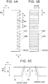
FIG. 5A is a partial plan view of a broken line part A ofFIG. 4 along the lateral direction and the thickness direction in the intervening member according to the embodiment; -
FIG. 5B is a partial plan view of the broken line part A ofFIG. 4 along the vertical direction and the thickness direction in the intervening member according to the embodiment; -
FIG. 5C is a partial plan view of the broken line part A ofFIG. 4 along the lateral direction and the vertical direction in the intervening member according to the embodiment; -
FIG. 6 is a flowchart of a manufacturing method of a battery pack according to the embodiment; -
FIG. 7 is an explanatory view illustrating a state where a bottom face (a heat dissipation surface), of a cell, that is exposed in a communicating passage of the intervening member faces a heat conductive viscous film formed on a cooling surface of a cooler in an integration step of the manufacturing method of the battery pack according to the embodiment; -
FIG. 8 is an explanatory view illustrating an original state where the heat conductive viscous film makes contact with the bottom surface of the cell in the integration step of the manufacturing method of the battery pack according to the embodiment; -
FIG. 9 is an explanatory view illustrating a state where the heat conductive viscous film also makes contact with a communicating-passage side wall portion of the intervening member in addition to the bottom surface of the cell in the integration step of the manufacturing method of the battery pack according to the embodiment; -
FIG. 10 is an explanatory view illustrating a state where a heat conductive viscous material moves toward the cooling surface side along the bottom face of the cell and the communicating-passage side wall portion of the intervening member in the integration step of the manufacturing method of the battery pack according to the embodiment; -
FIG. 11 is an explanatory view illustrating a state where the heat conductive viscous material is filled into the communicating passage without any gap and a heat conductive layer is formed in the integration step of the manufacturing method of the battery pack according to the embodiment; and -
FIG. 12 is a graph illustrating a maximum temperature of a cell temperature at the time of cooling in terms of a battery pack of each of Examples 1 to 6 and Comparative Example. - An embodiment of the invention will be described below with reference to the drawings.
FIGS. 1 to 3 each illustrate a perspective view or a sectional view of abattery pack 1 according to the present embodiment. Note that the following description will be made such that an arrangement direction BH, a lateral direction CH, and a vertical direction DH of thebattery pack 1 are defined as directions illustrated inFIGS. 1 to 3 . Thebattery pack 1 is an in-vehicle battery pack to be provided in a vehicle such as an electric vehicle and a plug-in hybrid car. Thebattery pack 1 includes abattery pack case 10, abattery module 20 accommodated in thebattery pack case 10 and configured such that a plurality ofcells 21 and a plurality of interveningmembers 31 are integrated with each other, and a cooler 60 accommodated in thebattery pack case 10 and configured to cool down thecells 21 included in thebattery module 20. Further, a heatconductive layer 70 is provided between bottom faces (heat dissipation surfaces) 23b of thecells 21 included in thebattery module 20 and acooling surface 60a of the cooler 60, and thecells 21 of thebattery module 20 and the cooler 60 are integrated with each other via the heatconductive layer 70. - Among them, the
battery pack case 10 is made of aluminum and includes alower case 11 and an upper case (not shown) fixed to thelower case 11. Thebattery module 20 is configured such that thecells 21 having a square shape and the interveningmembers 31 are laminated alternately, andend plates 29 are placed on the opposite sides in the laminating direction (the arrangement direction BH) so as to sandwich thecells 21 and the interveningmembers 31 therebetween. They are restricted by a plurality of restraint members (not shown) provided over theend plates 29 in a pressed state in the arrangement direction BH so that they are integrated with each other. - The
cell 21 is an encapsulated-type lithium ion secondary battery having a rectangular-solid shape. Thecells 21 included in thebattery module 20 are arranged in a cell-thickness direction IH. Thecells 21 are connected in series to each other by a bus bar (not shown). Thecell 21 is configured such that an electrode body (not shown) and an electrolytic solution (not shown) are accommodated inside acell case 23 having a rectangular box shape and made of metal (aluminum in the present embodiment). The electrode body is configured such that a belt-shaped positive plate and a belt-shaped negative plate are laminated via a pair of belt-shaped separators and are wound into a flat shape. Thecell case 23 has atop face 23a, abottom face 23b, a pair of first side faces 23c with a large area, and a pair of second side faces 23d with a small area. Note that, in the present embodiment, thebottom face 23b of thecell case 23 corresponds to the "heat dissipation surface." - A
positive terminal member 25 made of aluminum and anegative terminal member 26 made of copper are provided on thetop face 23a of thecell case 23 in a projecting manner in a state where they are insulated from thecell case 23. Thepositive terminal member 25 is connected to the positive plate of the electrode body inside thecell case 23 in a conductive manner and penetrates through thetop face 23a of thecell case 23 so as to extend outside the cell. Further, thenegative terminal member 26 is connected to the negative plate of the electrode body inside thecell case 23 in a conductive manner and penetrates through thetop face 23a of thecell case 23 so as to extend outside the cell. - Next will be described the intervening member 31 (see
FIGS. 4 ,5A, 5B, and 5C in addition toFIGS. 1 to 3 ). Note that the following description will be made such that a thickness direction EH, a lateral direction FH, and a vertical direction GH of the interveningmember 31 are defined as directions illustrated inFIG. 4 and so on. The interveningmember 31 is made of insulating resin in an integrated manner. The interveningmember 31 is constituted by a plate-shaped first interveningportion 33 expanding in the lateral direction FH and the vertical direction GH, a plate-shaped second interveningportion 35 expanding in the thickness direction EH and the lateral direction FH, and a pair of plate-shaped third interveningportions 37 expanding in the thickness direction EH and the vertical direction GH. - The
first intervening portion 33 and thesecond intervening portion 35 are connected such that a lower end (the lower side inFIG. 4 ), in the vertical direction GH, of the first interveningportion 33 is connected to a first end (the upper right side inFIG. 4 ), in the thickness direction EH, of thesecond intervening portion 35. Further, the first interveningportion 33 and thethird intervening portions 37 are connected such that opposite ends (the right side and the left side inFIG. 4 ), in the lateral direction FH, of the first interveningportion 33 are connected to respective first ends (the upper right side inFIG. 4 ), in the thickness direction EH, of thethird intervening portions 37. Further, thesecond intervening portion 35 and thethird intervening portions 37 are connected such that opposite ends (the right side and the left side inFIG. 4 ), in the lateral direction FH, of thesecond intervening portion 35 are connected to respective lower ends (the lower side inFIG. 4 ), in the vertical direction GH, of thethird intervening portions 37. - The
first intervening portion 33 is a part making contact with the wholefirst side face 23c with a large area in thecell 21, and in a state where thebattery module 20 is formed, the first interveningportion 33 is provided between respective first side faces 23c of thecells 21 adjacent to each other. Further, thesecond intervening portion 35 is a part making contact with thebottom face 23b of thecell 21, and in a state where thebattery module 20 and thebattery pack 1 are formed, thesecond intervening portion 35 is provided between thebottom face 23b of thecell 21 and thecooling surface 60a of the cooler 60. Further, thethird intervening portions 37 are parts making contact with the second side faces 23d with a small area in thecell 21 so as to cover the second side faces 23d from outside. - Among them, a second thickness T2 (thickness) that is a thickness of the second intervening portion 35 (the dimension, in a thickness direction JH, that connects the
bottom face 23b of thecell 21 to thecooling surface 60a of the cooler 60 (described later)) is set to T2 = 1.5 mm. Further, thesecond intervening portion 35 is provided with a communicatingpassage 35k having a notch shape so that thebottom face 23b of thecell 21 communicates with thecooling surface 60a of the cooler 60 via the communicatingpassage 35k. The communicatingpassage 35k is formed in a rectangular shape in a plan view so as to be provided in a central part, in the lateral direction FH, of thesecond intervening portion 35 over the thickness direction EH. - The
second intervening portion 35 has a pair of communicating-passageside wall portions 35f forming the communicatingpassage 35k, and the communicating-passageside wall portions 35f have a tapered shape directed outward (the right side and the left side inFIG. 4 ) in a cooling-surface direction RH along the coolingsurface 60a (in the thickness direction EH and the lateral direction FH of the interveningmember 31, the arrangement direction BH and the lateral direction CH of the battery pack 1) as they go from thebottom face 23b of thecell 21 toward thecooling surface 60a side of the cooler 60. In other words, the communicating-passageside wall portions 35f have a tapered shape directed outward in the longitudinal direction of the second intervening portion as they go from theheat dissipation surface 23b toward thecooling surface 60a. An inclination angle θ of the tapered shape is 0.3° to 4° (θ = 3.0° in the present embodiment). - Further, the communicating-passage
side wall portion 35f has an uneven shape in which protrusion portions 35f1 and recess portions 35f2 extending from thebottom face 23b side of thecell 21 toward thecooling surface 60a side of the cooler 60 are arranged alternately in a stripe manner (seeFIGS. 5A, 5B, and 5C ). In the present embodiment, a width W1 of each protrusion portion 35f1 is set to W1 = 0.15 mm, a width W2 of each recess portion 35f2 is set to W2 = 0.15 mm, and a repetition distance P of the protrusion portions 35f1 is set to P = 0.30 mm. Further, a depth D of the recess portion 35f2 based on the apex of the protrusion portion 35f1 is set to D = 0.15 mm. - The
end plates 29 are placed on the opposite sides in the arrangement direction BH so that thecells 21 and the interveningmembers 31 that are laminated on each other are sandwiched therebetween. Theend plates 29 are provided with a plurality of fixing portions (not shown) via which thebattery module 20 is fixed to thelower case 11 of thebattery pack case 10 and are fixed to thelower case 11 together with the cooler 60 (described later) by use of stud bolts and nuts (not shown). Hereby, thebattery module 20 is fixed to thelower case 11 in a state where the cooler 60 is sandwiched between the bottom faces 23b of thecells 21 of thebattery module 20 and thelower case 11. - Next will be described the cooler 60 (see
FIGS. 1 to 3 ). The cooler 60 is placed below thebattery module 20. The cooler 60 is made of aluminum and has a square tubular shape extending in the arrangement direction BH. The cooler 60 is configured such that a cooling medium RB (a cooling medium for an in-vehicle air conditioner, in the present embodiment) cooled to a predetermined temperature (10°C, in the present embodiment) circulates through the cooler 60. Further, a plate-shapedmember 15 made of sponge having an excellent heat insulating property and extending in the arrangement direction BH is placed between thebottom face 60b of the cooler 60 and thelower case 11 of thebattery pack case 10. - The cooler 60 is provided with a plurality of fixing portions (not shown) via which the cooler 60 is fixed to the
battery pack case 10. As described above, by use of stud bolts and nuts (not shown), the cooler 60 is fixed to thelower case 11 of thebattery pack case 10 together with thebattery module 20 with the plate-shapedmember 15 being sandwiched therebetween. In such an assembled state, a distance KC between the bottom faces 23b of thecells 21 and thecooling surface 60a that is a top face, of the cooler 60, that extends in the arrangement direction BH is set to KC = 1.8 mm. - The heat
conductive layer 70 is a layer provided between the bottom faces 23b of thecells 21 and thecooling surface 60a of the cooler 60 so as to transmit heat of thecells 21 to the cooler 60. The heatconductive layer 70 is a layer made of a heat conductiveviscous material 71 and having heat conductivity and viscosity, and more specifically, in the present embodiment, the heatconductive layer 70 is made of heat dissipation grease. The heat dissipation grease has a viscosity of 672 Pa·s and contains aluminum oxide (Al2O3) by 45 wt% to 50 wt%, zinc oxide (ZnO) by 17 wt% to 21 wt%, and grease-form silicon-based resin by 30 wt%. - The heat
conductive layer 70 is filled into the communicatingpassage 35k of the interveningmember 31 without any gap and is also provided between thesecond intervening portion 35 of the interveningmember 31 and thecooling surface 60a of the cooler 60. Note that, in the heatconductive layer 70, a part filled in the communicatingpassage 35k is also referred to as a communicating-passage insidepart 70p, and a part provided between thesecond intervening portion 35 and thecooling surface 60a is also referred to as a communicating-passage outsidepart 70q. - A layer thickness (a layer thickness in the communicating-passage inside
part 70p) TD of the heatconductive layer 70 is equal to the distance KC (KC = 1.8 mm) between thebottom face 23b of thecell 21 and thecooling surface 60a of the cooler 60, that is, TD = KC = 1.8 mm is satisfied. The layer thickness TD is thicker than the second thickness T2 (T2 = 1.5 mm) of thesecond intervening portion 35 of the intervening member 31 (seeFIG. 11 ). As will be described later, in thebattery pack 1 of the present embodiment, no air bubble AR remains in the communicating-passage insidepart 70p of the heatconductive layer 70, so that a heat transfer amount Q (W) (of the heat conductive layer 70) between thebottom face 23b of thecell 21 and thecooling surface 60a of the cooler 60 is high. - Next will be described a manufacturing method of the battery pack 1 (see
FIGS. 6 to 11 ). First, thecells 21, the interveningmembers 31, and theend plates 29 are prepared, and in a "module forming step S1," thebattery module 20 is formed. More specifically, thecells 21 and thefirst intervening portions 33 of the interveningmembers 31 are arranged alternately, so that each of thefirst intervening portions 33 of the interveningmembers 31 is provided between correspondingcells 21 adjacent to each other and the bottom faces 23b of thecells 21 are exposed in the communicatingpassages 35k of thesecond intervening portions 35 of the interveningmembers 31. Further, theend plates 29 are laminated on the opposite sides in the arrangement direction BH so as to sandwich thecells 21 and the interveningmembers 31 therebetween. Then, while a laminated body obtained herein is being pressed in the arrangement direction BH, a restraint member (not shown) is provided over theend plates end plates 29, so that thecells 21 and the interveningmembers 31 are integrated with each other. Thus, thebattery module 20 is formed. - Further, the cooler 60 is prepared separately, and in a "film forming step S2," the heat conductive
viscous material 71 is discharged onto thecooling surface 60a of the cooler 60 by use of a dispenser with a predetermined discharge amount, so that a heat conductiveviscous film 70x made of the heat conductiveviscous material 71 is formed on thecooling surface 60a. Note that values of a width TW and a film thickness TM of the heat conductiveviscous film 70x (seeFIG. 7 ) are values obtained when the communicatingpassage 35k of the interveningmember 31 is filled with the heat conductiveviscous material 71 without any gap and the heat conductiveviscous material 71 is also provided between thesecond intervening portion 35 of the interveningmember 31 and thecooling surface 60a of the cooler 60 at the time when the heatconductive layer 70 is formed by crushing the heat conductiveviscous film 70x in an integration step S3 (described later). - In the present embodiment, in the communicating
passage 35k of the interveningmember 31, a maximum opening width W3 on thecooling surface 60a side of the cooler 60 is set to W3 = 25.0 mm and a minimum opening width W4 on thebottom face 23b side of thecell 21 is set to W4 = 24.8 mm. Further, a depth of the communicatingpassage 35k (the second depth T2 of thesecond intervening portion 35 of the intervening member 31) is set to T2 =1.5 mm. In the meantime, the layer thickness TD of the heatconductive layer 70 formed in the integration step S3 (described later) is set to TD = 1.8 mm. In view of this, the width TW of the heat conductiveviscous film 70x is set to TW = 23.0 mm that is smaller than the maximum opening width W3 of the communicatingpassage 35k and also smaller than the minimum opening width W4, and the film thickness TM of the heat conductiveviscous film 70x is set to TM = 2.0 mm that is thicker than the depth (the second thickness T2) of the communicatingpassage 35k and also thicker than the layer thickness TD of the heatconductive layer 70. - Subsequently, in the "integration step S3," the
cells 21 of thebattery module 20 and the cooler 60 are integrated with each other via the heatconductive layer 70. More specifically, the plate-shapedmember 15 is positioned and put on thelower case 11 of thebattery pack case 10. Further, the cooler 60 is positioned and put on the plate-shapedmember 15. After that, thebattery module 20 is positioned and put on the cooler 60. Then, the fixing portions (not shown) of the cooler 60 and the fixing portions (not shown) of thebattery module 20 are fixed to thelower case 11 by use of stud bolts and nuts (not shown). Hereby, the distance KC between the bottom faces 23b of thecells 21 and thecooling surface 60a of the cooler 60 is set to KC = 1.8 mm, so that the heatconductive layer 70 with the layer thickness TD that is set to TD = KC = 1.8 mm is formed. -
FIGS. 7 to 11 illustrate a state where the heat conductiveviscous film 70x is crushed to deform so that the heatconductive layer 70 is formed in the integration step S3.FIG. 7 illustrates a state where thebattery module 20 is put on the cooler 60 on which the heat conductiveviscous film 70x is formed, in such a posture that thebottom face 23b, of thecell 21, that is exposed in the communicatingpassage 35k of the interveningmember 31 faces thecooling surface 60a of the cooler 60. At this stage, the heat conductiveviscous film 70x does not make contact with thebottom face 23b of thecell 21. - When the distance KC between the
bottom face 23b of thecell 21 and thecooling surface 60a of the cooler 60 is further narrowed, the heat conductiveviscous film 70x makes contact with thebottom face 23b of thecell 21 as illustrated inFIG. 8 , so that the heat conductiveviscous film 70x is slightly crushed in the thickness direction (the same direction as the thickness direction JH of the second intervening portion 35) and a central part, in the thickness direction, of the heat conductiveviscous film 70x swells outward. At this stage, the heat conductiveviscous film 70x does not make contact with the communicating-passageside wall portions 35f of thesecond intervening portion 35 of the interveningmember 31. - When the distance KC between the
bottom face 23b and thecooling surface 60a is further narrowed, the heat conductiveviscous film 70x is further crushed in the thickness direction, so that the heat conductiveviscous film 70x makes contact with the communicating-passageside wall portions 35f of thesecond intervening portion 35 of the interveningmember 31, as well as thebottom face 23b of thecell 21, as illustrated inFIG. 9 . At this time, since the central part, in the thickness direction, of the heat conductiveviscous film 70x makes contact with the communicating-passageside wall portions 35f first, so that an air bubble AR may be left at corner parts BF between thebottom face 23b of thecell 21 and the communicating-passageside wall portions 35f of the interveningmember 31. - When the distance KC between the
bottom face 23b and thecooling surface 60a is further narrowed, the heat conductiveviscous film 70x is further crushed in the thickness direction. As a result, as illustrated inFIG. 10 , the heat conductiveviscous material 71 making contact with thebottom face 23b of thecell 21 and the communicating-passageside wall portions 35f gradually moves toward thecooling surface 60a side of the cooler 60 along thebottom face 23b of thecell 21 and the communicating-passageside wall portions 35f. On this account, air bubbles AR left at the corner parts BF between thebottom face 23b of thecell 21 and the communicating-passageside wall portions 35f also gradually move toward thecooling surface 60a side along the communicating-passageside wall portions 35f, along with the movement of the heat conductiveviscous material 71. - When the distance KC between the
bottom face 23b and thecooling surface 60a is further narrowed, the heat conductiveviscous material 71 is filled into the communicatingpassage 35k without any gap, as illustrated inFIG. 11 . Along with this, the heat conductiveviscous material 71 partially protrudes from the communicatingpassage 35k and expands between thesecond intervening portion 35 of the interveningmember 31 and thecooling surface 60a of the cooler 60. Thus, the heatconductive layer 70 is formed. Besides, the air bubbles AR left in the communicatingpassage 35k in the communicating-passage insidepart 70p of the heatconductive layer 70 move to a part between thesecond intervening portion 35 of the interveningmember 31 and thecooling surface 60a of the cooler 60 and are further pushed outside, so that the air bubbles AR can hardly stay in the communicating-passage insidepart 70p. - Subsequently, in an "upper case attachment step S4," the upper case (not shown) is fixed to the
lower case 11, so that thebattery pack case 10 is formed. Thus, thebattery pack 1 is completed. - Next will be described results of tests performed to verify the effects of the invention. As Examples 1 to 6 and Comparative Example, seven types of battery packs were manufactured by changing the configuration of the communicating-passage side wall portion of the second intervening portion of the intervening member, as illustrated in Table 1. More specifically, in Comparative Example and Example 3, the communicating-passage side wall portion of the second intervening portion did not have a tapered shape. On the other hand, in Examples 1, 2, 4 to 6, the communicating-passage side wall portion of the second intervening portion was formed in a tapered shape having an inclination angle θ of 0.5° to 3.0°. In the meantime, in Examples 3 to 6, the communicating-passage side wall portion of the second intervening portion was formed in an uneven shape similar to the uneven shape constituted by the protrusion portions 35f1 and the recess portions 35f2 in the embodiment described above. Note that the battery pack of Example 6 corresponds to the
battery pack 1 of the above embodiment.Table 1 INCLINATION ANGLE θ (°) PROTRUSION PORTIONS AND RECESS PORTIONS FORMED OR NOT MAXIMUM TEMPERATURE (°C) EVALUATION COMPARATIVE EXAMPLE 0.0 NOT FORMED 35.0 C EXAMPLE 1 1.0 NOT FORMED 33.0 B EXAMPLE 2 3.0 NOT FORMED 34.0 B EXAMPLE 3 0.0 FORMED 33.2 B EXAMPLE 4 0.5 FORMED 31.4 A EXAMPLE 5 1.0 FORMED 30.9 A EXAMPLE 6 3.0 FORMED 29.5 A - Then, the battery packs of Examples 1 to 6 and Comparative Example were used under a predetermined condition. More specifically, while the cooling medium RB cooled off to 10°C was circulated through the cooler 60, charge and discharge were repeated for 2000 sec such that the
cells 21 included in the battery pack were discharged at a constant current of 3C from SOC of 100 % to SOC of 90 %, and after that, thecells 21 were charged at a constant current of 3C from SOC of 90 % to SOC of 100 %. Then, cell temperatures (°C) of the top faces 23a of thecell cases 23 of thecells 21 included in the battery pack were measured. Note that the cell temperature was measured by use of a thermoelectric couple placed on thetop face 23a of thecell case 23 of thecell 21. - Note that "MAXIMUM TEMPERATURE" in Table 1 is a cell temperature of the
cell 21 having the highest temperature among thecells 21 included in one battery pack. In the test, based on the height of the maximum temperature, cooling performance of the battery pack was evaluated. More specifically, a battery pack with a maximum temperature of less than 32.0°C was evaluated as particularly good (an evaluation mark "A"), a battery pack with a maximum temperature of equal to or more than 32.0°C but less than 34.5°C was evaluated as good (an evaluation mark "B"), and a battery pack with a maximum temperature of 34.5°C or more was evaluated as poor (an evaluation mark "C"). - The results are shown in Table 1 and
FIG. 12 . In the battery pack of Comparative Example, the maximum temperature was high (34.5°C or more), so the cooling performance was poor. On the other hand, in the battery packs of Examples 1 to 6, the maximum temperature was low (less than 34.5°C), so the cooling performance was good. Particularly, in the battery packs of Examples 4 to 6, the maximum temperature was low (less than 32.0°C), so the cooling performance was good. A presumable reason why such results were obtained is as follows. - That is, in the battery pack of Comparative Example, the communicating-passage side wall portion of the second intervening portion of the intervening member did not have a tapered shape and also did not have an uneven shape. On this account, an air bubble AR left in the communicating
passage 35k, particularly at the corner part BF between thebottom face 23b of thecell 21 and the communicating-passageside wall portion 35f of the interveningmember 31 in the step of forming the heatconductive layer 70 remained in the communicating-passage insidepart 70p of the heatconductive layer 70, so that the heat transfer amount Q of the heatconductive layer 70 was low (a heat dissipation property was low). As a result, it is considered that the maximum temperature of thecells 21 was high. - On the other hand, in the battery packs of Examples 1, 2, 4 to 6, the communicating-passage side wall portion of the second intervening portion of the intervening member was formed in the tapered shape. On this account, even if air bubbles AR were left in the communicating
passage 35k, particularly at the corner part BF in the step of forming the heatconductive layer 70, the air bubbles AR moved toward thecooling surface 60a side along thebottom face 23b of thecell 21 and the communicating-passageside wall portion 35f formed in the tapered shape, along with the movement of the heat conductiveviscous material 71 toward thecooling surface 60a of the cooler 60 along thebottom face 23b of thecell 21 and the communicating-passageside wall portion 35f formed in the tapered shape, so that the air bubbles AR were easily discharged outside the communicatingpassage 35k. Thus, the air bubbles AR left in the communicating-passage insidepart 70p of the heatconductive layer 70 were fewer than the battery pack of Comparative Example, and the heat transfer amount Q of the heatconductive layer 70 was high. As a result, it is considered that the maximum temperature of thecells 21 was restrained to be low. - From those results, it is found that the inclination angle θ of the communicating-passage side wall portion of the intervening member should be set to 0.3° or more. When the inclination angle θ is less than 0.3°, it is considered that the air bubbles AR can hardly move along with the movement of the heat conductive
viscous material 71, so that the air bubbles AR easily remain in the communicating-passage insidepart 70p. In the meantime, the inclination angle θ of the communicating-passage side wall portion of the intervening member should be set to 4° or less. In a battery pack having a tapered shape with an inclination angle θ of larger than 4°, the heat conductiveviscous material 71 can hardly move to thecooling surface 60a side, so it is considered that the air bubbles AR tend to remain in the communicating-passage insidepart 70p. Accordingly, it is preferable that the communicating-passage side wall portion of the intervening member be formed in a tapered shape having an inclination angle θ of 0.3° to 4°. - In the meantime, in the battery packs of Examples 3 to 6, the communicating-passage side wall portion of the second intervening portion of the intervening member was formed in an uneven shape. On this account, in the integration step S3, the heat conductive
viscous material 71 easily moved toward thecooling surface 60a side along the extending direction of the protrusion portions and the recess portions. That is, it is considered that the heat conductiveviscous material 71 easily moved from thebottom face 23b of thecell 21 toward thecooling surface 60a side by providing the protrusion portions and the recess portions. Hereby, the air bubbles AR easily moved toward thecooling surface 60a side so as to be discharged outside the communicatingpassage 35k, along with the movement of the heat conductiveviscous material 71 to thecooling surface 60a side. Thus, the air bubbles AR left in the communicating-passage insidepart 70p of the heatconductive layer 70 were fewer than the battery pack of Comparative Example, and the heat transfer amount Q of the heatconductive layer 70 was high. As a result, it is considered that the maximum temperature of thecells 21 was restrained to be low. - Particularly, in Examples 4 to 6, the communicating-passage side wall portion of the intervening member had the tapered shape and the uneven shape. On this account, in the integration step S3, the heat conductive
viscous material 71 further easily moved toward thecooling surface 60a side along thebottom face 23b of thecell 21 and the communicating-passageside wall portion 35f having the tapered shape and the uneven shape. Along with this, the air bubbles AR were further easily discharged outside the communicatingpassage 35k by further moving toward thecooling surface 60a side along thebottom face 23b of thecell 21 and the communicating-passageside wall portion 35f having the tapered shape and the uneven shape. Thus, the air bubbles AR left in the communicating-passage insidepart 70p of the heatconductive layer 70 were further fewer than the battery packs of Examples 1 to 3, and the heat transfer amount Q of the heatconductive layer 70 was further higher. As a result, it is considered that the maximum temperature of thecells 21 was restrained to be particularly low. - As described above, the manufacturing method of the
battery pack 1 includes the module forming step S1, the film forming step S2, and the integration step S3. The communicating-passageside wall portion 35f of thesecond intervening portion 35 of the interveningmember 31 is formed at least in the tapered shape or the uneven shape. In the integration step S3, the heat conductiveviscous film 70x is pressed against thebottom face 23b, of thecell 21, that is exposed in the communicatingpassage 35k of the interveningmember 31, and the heat conductiveviscous material 71 making contact with thebottom face 23b of thecell 21 and the communicating-passageside wall portion 35f having the tapered shape and the uneven shape is moved toward thecooling surface 60a side along thebottom face 23b of thecell 21 and the communicating-passageside wall portion 35f having the tapered shape and the uneven shape. On this account, even if the air bubbles AR are left in the communicatingpassage 35k, the air bubbles AR easily move toward thecooling surface 60a side along with the movement of the heat conductiveviscous material 71, so that the air bubbles AR can hardly remain in the heat conductiveviscous material 71 filled in the communicatingpassage 35k. On this account, it is possible to restrain the air bubbles AR from remaining in the communicating-passage insidepart 70p of the heatconductive layer 70 and to restrain a decrease of the heat transfer amount Q of the heatconductive layer 70 due to the air bubbles AR. - In a case where the communicating-passage
side wall portion 35f of thesecond intervening portion 35 of the interveningmember 31 is formed to have the tapered shape and the uneven shape, it is possible to particularly restrain the air bubbles AR from remaining in the communicating-passage insidepart 70p of the heatconductive layer 70 and to further restrain the decrease of the heat transfer amount Q of the heatconductive layer 70 due to the air bubbles AR. - Further, in the present embodiment, the communicating-passage
side wall portion 35f of the interveningmember 31 is formed in a tapered shape having an inclination angle θ of 0.3° to 4°. On this account, in the integration step S3, the heat conductiveviscous material 71 further easily moves toward thecooling surface 60a side along thebottom face 23b of thecell 21 and the communicating-passageside wall portion 35f having the tapered shape, so that the air bubbles AR can hardly remain in the heat conductiveviscous material 71 filled in the communicatingpassage 35k. Thus, it is possible to further restrain the air bubbles AR from remaining in the communicating-passage insidepart 70p of the heatconductive layer 70 and to further restrain the decrease of the heat transfer amount Q of the heatconductive layer 70 due to the air bubbles AR. - The invention has been described above in line with the embodiment, but the invention also includes a case where the tapered shape is configured such that the sectional area of the communicating passage, in a direction perpendicular to the thickness direction of the second intervening portion, increases. The invention is not limited to the embodiment and can be modified and applied appropriately without departing from the gist of the invention.
Claims (12)
- A battery pack (1) comprising:a battery module (20) configured such that a plurality of cells (21) and a plurality of intervening members (31) are integrated with each other, the cells (21) each including a heat dissipation surface (23b), the intervening members (31) each including a first intervening portion (33) to be provided between corresponding cells (21) adjacent to each other;a cooler (60) configured to cool the cells (21) via a cooling surface (60a) of the cooler (60); anda heat conductive layer (70) including a heat conductive viscous material (71) and provided between the heat dissipation surface (23b) and the cooling surface (60a), wherein:the cells (21) and the cooler (60) are integrated with each other via the heat conductive layer (70);the intervening members (31) each include a second intervening portion (35) to be provided between the heat dissipation surface (23b) and the cooling surface (60a);the second intervening portion (35) has a thickness (T2) in a thickness direction (JH) from the heat dissipation surface (23b) to the cooling surface (60a);the second intervening portion (35) includes a communicating-passage side wall portion (35f) defining a communicating passage (35k) via which the heat dissipation surface (23b) communicates with the cooling surface (60a);the communicating-passage side wall portion (35f) has at least one of a tapered shape and an uneven shape, the tapered shape being configured such that a sectional area of the communicating passage (35k), in a direction perpendicular to the thickness direction of the second intervening portion (35), increases along a direction from the heat dissipation surface (23b) toward the cooling surface (60a), the uneven shape being configured such that protrusion portions (35f1) each extending from the heat dissipation surface (23b) toward the cooling surface (60a) and recess portions (35f2) each extending from the heat dissipation surface (23b) toward the cooling surface (60a) are arranged alternately in a stripe manner;the heat conductive layer (70) has a layer thickness (TD) that is equal to or more than the thickness (T2) of the second intervening portion (35); andthe heat conductive layer (70) is filled in at least the communicating passage (35k), out of the communicating passage (35k) and a part between the second intervening portion (35) and the cooling surface (60a).
- The battery pack (1) according to claim 1, wherein:the cells (21) are arranged in line;the cooling surface (60a) is configured to extend in an arrangement direction (BH) where the cells (21) are arranged in line;the heat conductive layer (70) is configured to transmit heat of the cells (21) to the cooler (60); andthe tapered shape is configured to be directed outward in a longitudinal direction of the second intervening portion (35) along the direction from the heat dissipation surface (23b) toward the cooling surface (60a).
- The battery pack (1) according to claim 1 or 2, wherein the communicating-passage side wall portion (35f) has the tapered shape and the uneven shape.
- The battery pack (1) according to any one of claims 1 to 3, wherein the communicating-passage side wall portion (35f) has the tapered shape with an inclination angle of 0.3° to 4° from the thickness direction (JH) of the second intervening portion (35).
- A manufacturing method of a battery pack (1), the manufacturing method comprising:forming a battery module (20) such that a plurality of cells (21) and a plurality of intervening members (31) are arranged alternately such that a first intervening portion (33) of each of the intervening members (31) is provided between the cells (21) adjacent to each other and heat dissipation surface (23b) of the cell (21) is exposed in communicating passage (35k) of the intervening member (31), and the cells (21) and the intervening members (31) are integrated with each other;forming, on a cooling surface (60a) of a cooler (60), a heat conductive viscous film (70x) including a heat conductive viscous material (71) and having a film thickness (TM); andforming a heat conductive layer (70) such that the cells (21) and the cooler (60) are integrated with each other via the heat conductive layer (70), the heat conductive layer (70) being formed such that the battery module (20) is put on the cooler (60) on which the heat conductive viscous film (70x) is formed, in such a posture that the heat dissipation surface (23b) exposed in the communicating passage (35k) faces the cooling surface (60a), the heat conductive viscous film (70x) is pressed against the heat dissipation surface (23b) exposed in the communicating passage (35k), and the heat conductive viscous material (71) making contact with the heat dissipation surface (23b) and communicating-passage side wall portion (35f) of the intervening members (31) is moved in a direction from the heat dissipation surface (23b) to the cooling surface (60a) along the heat dissipation surface (23b) and the communicating-passage side wall portion (35f), such that the communicating passage (35k) is filled with the heat conductive viscous material (71), wherein:the intervening members (31) each include a second intervening portion (35) to be provided between the heat dissipation surface (23b) and the cooling surface (60a);the second intervening portion (35) has a thickness (T2) in a thickness direction (JH) from the heat dissipation surface (23b) to the cooling surface (60a);the second intervening portion (35) includes the communicating-passage side wall portion (35f) defining the communicating passage (35k) via which the heat dissipation surface (23b) communicates with the cooling surface (60a);the communicating-passage side wall portion (35f) has at least one of a tapered shape and an uneven shape, the tapered shape being configured such that a sectional area of the communicating passage (35k), in a direction perpendicular to the thickness direction of the second intervening portion (35), increases along a direction from the heat dissipation surface (23b) toward the cooling surface (60a), the uneven shape being configured such that protrusion portions (35f1) each extending from the heat dissipation surface (23b) toward the cooling surface (60a) and recess portions (35f2) each extending from the heat dissipation surface (23b) toward the cooling surface (60a) are arranged alternately in a stripe manner;the heat conductive layer (70) has a layer thickness (TD) that is equal to or more than the thickness (T2) of the second intervening portion (35);the heat conductive layer (70) is filled in at least the communicating passage (35k), out of the communicating passage (35k) and a part between the second intervening portion (35) and the cooling surface (60a); andthe film thickness (TM) is thicker than the layer thickness (TD).
- The manufacturing method of a battery pack (1) according to claim 5, wherein:the cells (21) are arranged in line;the cooling surface (60a) is configured to extend in an arrangement direction (BH) where the cells (21) are arranged in line;the heat conductive layer (70) is configured to transmit heat of the cells (21) to the cooler (60); andthe tapered shape is configured to be directed outward in a longitudinal direction of the second intervening portion (35) along the direction from the heat dissipation surface (23b) toward the cooling surface (60a).
- The manufacturing method of a battery pack (1) according to claim 5 or 6, wherein the communicating-passage side wall portion (35f) has the tapered shape and the uneven shape.
- The manufacturing method of a battery pack (1) according to any one of claims 5 to 7, wherein the communicating-passage side wall portion (35f) has the tapered shape with an inclination angle of 0.3° to 4° from the thickness direction (JH) of the second intervening portion (35).
- An intervening member (31) used for a battery pack (1), the intervening member (31) comprising:a first intervening portion (33) to be provided between adjacent cells (21), the cells (21) each including a heat dissipation surface (23b); anda second intervening portion (35) to be provided between the heat dissipation surface (23b) and a cooling surface (60a) of a cooler (60),the second intervening portion (35) including a communicating-passage side wall portion (35f) defining a communicating passage (35k) via which the heat dissipation surface (23b) communicates with the cooling surface (60a),the communicating-passage side wall portion (35f) having at least one of a tapered shape and an uneven shape, the tapered shape being configured such that a sectional area of the communicating passage (35k), in a direction perpendicular to a thickness direction of the second intervening portion (35), increases along a direction from the heat dissipation surface (23b) toward the cooling surface (60a), the uneven shape being configured such that protrusion portions (35f1) each extending from the heat dissipation surface (23b) toward the cooling surface (60a)and recess portions (35f2) each extending from the heat dissipation surface (23b) toward the cooling surface (60a) are arranged alternately in a stripe manner.
- The intervening member (31) according to claim 9, wherein the tapered shape is configured to be directed outward in a longitudinal direction of the second intervening portion (35) along the direction from the heat dissipation surface (23b) toward the cooling surface (60a).
- The intervening member (31) according to claim 9 or 10, wherein the communicating-passage side wall portion (35f) has the tapered shape and the uneven shape.
- The intervening member (31) according to claim 9 or 11, wherein the communicating-passage side wall portion (35f) has the tapered shape with an inclination angle of 0.3° to 4° from the thickness direction of the second intervening portion (35).
Applications Claiming Priority (1)
| Application Number | Priority Date | Filing Date | Title |
|---|---|---|---|
| JP2017222049A JP6922683B2 (en) | 2017-11-17 | 2017-11-17 | Battery pack, battery pack manufacturing method and intervening members |
Publications (2)
| Publication Number | Publication Date |
|---|---|
| EP3486965A1 true EP3486965A1 (en) | 2019-05-22 |
| EP3486965B1 EP3486965B1 (en) | 2020-07-29 |
Family
ID=63762301
Family Applications (1)
| Application Number | Title | Priority Date | Filing Date |
|---|---|---|---|
| EP18198472.5A Active EP3486965B1 (en) | 2017-11-17 | 2018-10-03 | Battery pack, manufacturing method of battery pack, and intervening member |
Country Status (4)
| Country | Link |
|---|---|
| US (1) | US11075418B2 (en) |
| EP (1) | EP3486965B1 (en) |
| JP (1) | JP6922683B2 (en) |
| CN (1) | CN109802063B (en) |
Cited By (3)
| Publication number | Priority date | Publication date | Assignee | Title |
|---|---|---|---|---|
| CN111864135A (en) * | 2020-06-22 | 2020-10-30 | 比瑞科技(深圳)有限公司 | Lithium battery pack and lifting device for lifting lithium battery pack |
| CN113785436A (en) * | 2019-06-12 | 2021-12-10 | 株式会社Lg新能源 | Battery module, method of manufacturing the same, and battery pack including the same |
| EP4175025A4 (en) * | 2021-03-05 | 2024-03-06 | LG Energy Solution, Ltd. | Battery pack and device including same |
Families Citing this family (16)
| Publication number | Priority date | Publication date | Assignee | Title |
|---|---|---|---|---|
| WO2018022964A1 (en) | 2016-07-29 | 2018-02-01 | Crynamt Management Llc | Battery packs having structural members for improving thermal management |
| US11757149B1 (en) | 2016-09-20 | 2023-09-12 | Apple Inc. | Battery liquid quench system and methods of manufacture thereof |
| US10923788B1 (en) | 2016-11-30 | 2021-02-16 | Apple Inc. | Directed quench systems and components |
| US11870092B1 (en) | 2017-02-01 | 2024-01-09 | Apple Inc. | On-board vent gas abatement |
| JP6965717B2 (en) * | 2017-12-13 | 2021-11-10 | トヨタ自動車株式会社 | Battery pack manufacturing method |
| US11469471B1 (en) | 2018-02-02 | 2022-10-11 | Apple Inc. | Battery pack heat dispensing systems |
| KR20210000551A (en) * | 2019-06-25 | 2021-01-05 | 주식회사 엘지화학 | Battery pack and device including the same |
| KR20210011640A (en) | 2019-07-23 | 2021-02-02 | 에스케이이노베이션 주식회사 | Battery module |
| JP7494453B2 (en) * | 2019-09-04 | 2024-06-04 | 株式会社レゾナック | Heat exchanger |
| KR20210064935A (en) * | 2019-11-26 | 2021-06-03 | 주식회사 엘지에너지솔루션 | Battery module |
| JP7351204B2 (en) * | 2019-12-12 | 2023-09-27 | トヨタ自動車株式会社 | Battery stack and battery module using this battery stack |
| JP2022035425A (en) * | 2020-08-21 | 2022-03-04 | 株式会社豊田自動織機 | Battery system |
| CN112151910B (en) * | 2020-09-27 | 2022-02-18 | 中国第一汽车股份有限公司 | Liquid-cooled battery system and control method thereof |
| US11764431B2 (en) | 2020-10-22 | 2023-09-19 | Apple Inc. | Battery pack structures and systems |
| US12009655B2 (en) | 2021-09-15 | 2024-06-11 | Apple Inc. | Switchable pyro fuse |
| DE102021213041A1 (en) | 2021-11-19 | 2023-06-07 | Mahle International Gmbh | battery |
Citations (4)
| Publication number | Priority date | Publication date | Assignee | Title |
|---|---|---|---|---|
| DE102008010825A1 (en) * | 2008-02-23 | 2009-08-27 | Daimler Ag | Battery with a heat conducting plate and several single cells |
| WO2012013789A1 (en) * | 2010-07-29 | 2012-02-02 | E4V | System for cooling an electrical battery, and battery including such a system |
| JP2014229559A (en) | 2013-05-24 | 2014-12-08 | 株式会社デンソー | Battery pack and manufacturing method therefor |
| EP2955780A1 (en) * | 2013-06-07 | 2015-12-16 | LG Chem, Ltd. | Battery pack with enhanced safety against leakage of liquid-phase refrigerant |
Family Cites Families (8)
| Publication number | Priority date | Publication date | Assignee | Title |
|---|---|---|---|---|
| JPS5746612Y2 (en) * | 1978-12-15 | 1982-10-14 | ||
| JP2737582B2 (en) * | 1992-11-24 | 1998-04-08 | 松下電工株式会社 | Module substrate sealing frame |
| JP4402602B2 (en) * | 2005-01-27 | 2010-01-20 | 株式会社日立製作所 | Capacitor cooling structure and power conversion device |
| JP2012248339A (en) | 2011-05-25 | 2012-12-13 | Sanyo Electric Co Ltd | Power unit for electric power and vehicle with power unit |
| JP2013012441A (en) * | 2011-06-30 | 2013-01-17 | Sanyo Electric Co Ltd | Electric power source device and vehicle including the same |
| JP2017076526A (en) * | 2015-10-15 | 2017-04-20 | 株式会社豊田自動織機 | Battery module |
| JP6956355B2 (en) * | 2016-09-27 | 2021-11-02 | パナソニックIpマネジメント株式会社 | Battery module |
| CN107331918A (en) * | 2017-08-01 | 2017-11-07 | 安徽欧鹏巴赫新能源科技有限公司 | Module radiator and new energy battery bag |
-
2017
- 2017-11-17 JP JP2017222049A patent/JP6922683B2/en active Active
-
2018
- 2018-10-03 EP EP18198472.5A patent/EP3486965B1/en active Active
- 2018-10-05 US US16/152,744 patent/US11075418B2/en active Active
- 2018-10-15 CN CN201811195666.1A patent/CN109802063B/en active Active
Patent Citations (4)
| Publication number | Priority date | Publication date | Assignee | Title |
|---|---|---|---|---|
| DE102008010825A1 (en) * | 2008-02-23 | 2009-08-27 | Daimler Ag | Battery with a heat conducting plate and several single cells |
| WO2012013789A1 (en) * | 2010-07-29 | 2012-02-02 | E4V | System for cooling an electrical battery, and battery including such a system |
| JP2014229559A (en) | 2013-05-24 | 2014-12-08 | 株式会社デンソー | Battery pack and manufacturing method therefor |
| EP2955780A1 (en) * | 2013-06-07 | 2015-12-16 | LG Chem, Ltd. | Battery pack with enhanced safety against leakage of liquid-phase refrigerant |
Cited By (6)
| Publication number | Priority date | Publication date | Assignee | Title |
|---|---|---|---|---|
| CN113785436A (en) * | 2019-06-12 | 2021-12-10 | 株式会社Lg新能源 | Battery module, method of manufacturing the same, and battery pack including the same |
| EP3923371A4 (en) * | 2019-06-12 | 2022-04-20 | LG Energy Solution, Ltd. | Battery module, manufacturing method of same, and battery pack comprising battery module |
| CN113785436B (en) * | 2019-06-12 | 2024-01-30 | 株式会社Lg新能源 | Battery module, method of preparing the same, and battery pack including the same |
| CN111864135A (en) * | 2020-06-22 | 2020-10-30 | 比瑞科技(深圳)有限公司 | Lithium battery pack and lifting device for lifting lithium battery pack |
| CN111864135B (en) * | 2020-06-22 | 2023-07-18 | 比瑞科技(深圳)有限公司 | Lithium battery pack and lifting device for lifting lithium battery pack |
| EP4175025A4 (en) * | 2021-03-05 | 2024-03-06 | LG Energy Solution, Ltd. | Battery pack and device including same |
Also Published As
| Publication number | Publication date |
|---|---|
| JP2019096387A (en) | 2019-06-20 |
| JP6922683B2 (en) | 2021-08-18 |
| CN109802063B (en) | 2021-08-17 |
| US11075418B2 (en) | 2021-07-27 |
| EP3486965B1 (en) | 2020-07-29 |
| US20190157729A1 (en) | 2019-05-23 |
| CN109802063A (en) | 2019-05-24 |
Similar Documents
| Publication | Publication Date | Title |
|---|---|---|
| EP3486965B1 (en) | Battery pack, manufacturing method of battery pack, and intervening member | |
| US11387502B2 (en) | Battery module comprising a heat transfer component and a thermal expansion material between cells | |
| EP2475025A1 (en) | Electric storage device and electric storage apparatus | |
| US7892669B2 (en) | Middle or large-sized battery module | |
| KR101803958B1 (en) | A Battery Pack Case Having Efficient Cooling Structure | |
| US9564663B2 (en) | Battery module and battery assembly comprising the same | |
| US9219261B2 (en) | Battery pack | |
| EP3147964B1 (en) | Battery pack and battery device | |
| US10569634B2 (en) | Multi-functional cooling channel and busbar for battery cell pack | |
| US20160126514A1 (en) | Battery module | |
| JP2010157450A (en) | Battery system | |
| KR102235650B1 (en) | Secondary battery module, and secondary battery pack including the same | |
| KR102303680B1 (en) | Battery pack | |
| US20140038020A1 (en) | Power storage apparatus | |
| JP2019096431A (en) | Battery pack, and manufacturing method of unit cell used for battery pack | |
| CN109638374B (en) | Battery pack | |
| EP3038183A1 (en) | Battery pack | |
| WO2018166692A1 (en) | Battery cell, battery module containing said battery cell, and use thereof | |
| KR101957403B1 (en) | Cell Lead Connecting Apparatus and Battery module including the same | |
| DE102018117784B4 (en) | Battery arrangement with tab cooling for pouch cells | |
| KR102436424B1 (en) | Battery module | |
| US20240136614A1 (en) | Battery module | |
| US20240304932A1 (en) | Battery pack | |
| US20230344086A1 (en) | Battery module | |
| US20220376328A1 (en) | Secondary battery cooling structure |
Legal Events
| Date | Code | Title | Description |
|---|---|---|---|
| PUAI | Public reference made under article 153(3) epc to a published international application that has entered the european phase |
Free format text: ORIGINAL CODE: 0009012 |
|
| STAA | Information on the status of an ep patent application or granted ep patent |
Free format text: STATUS: REQUEST FOR EXAMINATION WAS MADE |
|
| 17P | Request for examination filed |
Effective date: 20181003 |
|
| AK | Designated contracting states |
Kind code of ref document: A1 Designated state(s): AL AT BE BG CH CY CZ DE DK EE ES FI FR GB GR HR HU IE IS IT LI LT LU LV MC MK MT NL NO PL PT RO RS SE SI SK SM TR |
|
| AX | Request for extension of the european patent |
Extension state: BA ME |
|
| STAA | Information on the status of an ep patent application or granted ep patent |
Free format text: STATUS: EXAMINATION IS IN PROGRESS |
|
| 17Q | First examination report despatched |
Effective date: 20191206 |
|
| GRAP | Despatch of communication of intention to grant a patent |
Free format text: ORIGINAL CODE: EPIDOSNIGR1 |
|
| STAA | Information on the status of an ep patent application or granted ep patent |
Free format text: STATUS: GRANT OF PATENT IS INTENDED |
|
| INTG | Intention to grant announced |
Effective date: 20200428 |
|
| GRAS | Grant fee paid |
Free format text: ORIGINAL CODE: EPIDOSNIGR3 |
|
| GRAA | (expected) grant |
Free format text: ORIGINAL CODE: 0009210 |
|
| STAA | Information on the status of an ep patent application or granted ep patent |
Free format text: STATUS: THE PATENT HAS BEEN GRANTED |
|
| AK | Designated contracting states |
Kind code of ref document: B1 Designated state(s): AL AT BE BG CH CY CZ DE DK EE ES FI FR GB GR HR HU IE IS IT LI LT LU LV MC MK MT NL NO PL PT RO RS SE SI SK SM TR |
|
| REG | Reference to a national code |
Ref country code: CH Ref legal event code: EP |
|
| REG | Reference to a national code |
Ref country code: AT Ref legal event code: REF Ref document number: 1296840 Country of ref document: AT Kind code of ref document: T Effective date: 20200815 |
|
| REG | Reference to a national code |
Ref country code: IE Ref legal event code: FG4D |
|
| REG | Reference to a national code |
Ref country code: DE Ref legal event code: R096 Ref document number: 602018006435 Country of ref document: DE |
|
| REG | Reference to a national code |
Ref country code: DE Ref legal event code: R079 Ref document number: 602018006435 Country of ref document: DE Free format text: PREVIOUS MAIN CLASS: H01M0002020000 Ipc: H01M0050100000 |
|
| REG | Reference to a national code |
Ref country code: LT Ref legal event code: MG4D |
|
| REG | Reference to a national code |
Ref country code: NL Ref legal event code: MP Effective date: 20200729 |
|
| REG | Reference to a national code |
Ref country code: AT Ref legal event code: MK05 Ref document number: 1296840 Country of ref document: AT Kind code of ref document: T Effective date: 20200729 |
|
| PG25 | Lapsed in a contracting state [announced via postgrant information from national office to epo] |
Ref country code: PT Free format text: LAPSE BECAUSE OF FAILURE TO SUBMIT A TRANSLATION OF THE DESCRIPTION OR TO PAY THE FEE WITHIN THE PRESCRIBED TIME-LIMIT Effective date: 20201130 Ref country code: GR Free format text: LAPSE BECAUSE OF FAILURE TO SUBMIT A TRANSLATION OF THE DESCRIPTION OR TO PAY THE FEE WITHIN THE PRESCRIBED TIME-LIMIT Effective date: 20201030 Ref country code: FI Free format text: LAPSE BECAUSE OF FAILURE TO SUBMIT A TRANSLATION OF THE DESCRIPTION OR TO PAY THE FEE WITHIN THE PRESCRIBED TIME-LIMIT Effective date: 20200729 Ref country code: HR Free format text: LAPSE BECAUSE OF FAILURE TO SUBMIT A TRANSLATION OF THE DESCRIPTION OR TO PAY THE FEE WITHIN THE PRESCRIBED TIME-LIMIT Effective date: 20200729 Ref country code: BG Free format text: LAPSE BECAUSE OF FAILURE TO SUBMIT A TRANSLATION OF THE DESCRIPTION OR TO PAY THE FEE WITHIN THE PRESCRIBED TIME-LIMIT Effective date: 20201029 Ref country code: SE Free format text: LAPSE BECAUSE OF FAILURE TO SUBMIT A TRANSLATION OF THE DESCRIPTION OR TO PAY THE FEE WITHIN THE PRESCRIBED TIME-LIMIT Effective date: 20200729 Ref country code: NO Free format text: LAPSE BECAUSE OF FAILURE TO SUBMIT A TRANSLATION OF THE DESCRIPTION OR TO PAY THE FEE WITHIN THE PRESCRIBED TIME-LIMIT Effective date: 20201029 Ref country code: AT Free format text: LAPSE BECAUSE OF FAILURE TO SUBMIT A TRANSLATION OF THE DESCRIPTION OR TO PAY THE FEE WITHIN THE PRESCRIBED TIME-LIMIT Effective date: 20200729 Ref country code: ES Free format text: LAPSE BECAUSE OF FAILURE TO SUBMIT A TRANSLATION OF THE DESCRIPTION OR TO PAY THE FEE WITHIN THE PRESCRIBED TIME-LIMIT Effective date: 20200729 Ref country code: LT Free format text: LAPSE BECAUSE OF FAILURE TO SUBMIT A TRANSLATION OF THE DESCRIPTION OR TO PAY THE FEE WITHIN THE PRESCRIBED TIME-LIMIT Effective date: 20200729 |
|
| PG25 | Lapsed in a contracting state [announced via postgrant information from national office to epo] |
Ref country code: PL Free format text: LAPSE BECAUSE OF FAILURE TO SUBMIT A TRANSLATION OF THE DESCRIPTION OR TO PAY THE FEE WITHIN THE PRESCRIBED TIME-LIMIT Effective date: 20200729 Ref country code: RS Free format text: LAPSE BECAUSE OF FAILURE TO SUBMIT A TRANSLATION OF THE DESCRIPTION OR TO PAY THE FEE WITHIN THE PRESCRIBED TIME-LIMIT Effective date: 20200729 Ref country code: LV Free format text: LAPSE BECAUSE OF FAILURE TO SUBMIT A TRANSLATION OF THE DESCRIPTION OR TO PAY THE FEE WITHIN THE PRESCRIBED TIME-LIMIT Effective date: 20200729 Ref country code: IS Free format text: LAPSE BECAUSE OF FAILURE TO SUBMIT A TRANSLATION OF THE DESCRIPTION OR TO PAY THE FEE WITHIN THE PRESCRIBED TIME-LIMIT Effective date: 20201129 |
|
| PG25 | Lapsed in a contracting state [announced via postgrant information from national office to epo] |
Ref country code: NL Free format text: LAPSE BECAUSE OF FAILURE TO SUBMIT A TRANSLATION OF THE DESCRIPTION OR TO PAY THE FEE WITHIN THE PRESCRIBED TIME-LIMIT Effective date: 20200729 |
|
| PG25 | Lapsed in a contracting state [announced via postgrant information from national office to epo] |
Ref country code: RO Free format text: LAPSE BECAUSE OF FAILURE TO SUBMIT A TRANSLATION OF THE DESCRIPTION OR TO PAY THE FEE WITHIN THE PRESCRIBED TIME-LIMIT Effective date: 20200729 Ref country code: DK Free format text: LAPSE BECAUSE OF FAILURE TO SUBMIT A TRANSLATION OF THE DESCRIPTION OR TO PAY THE FEE WITHIN THE PRESCRIBED TIME-LIMIT Effective date: 20200729 Ref country code: CZ Free format text: LAPSE BECAUSE OF FAILURE TO SUBMIT A TRANSLATION OF THE DESCRIPTION OR TO PAY THE FEE WITHIN THE PRESCRIBED TIME-LIMIT Effective date: 20200729 Ref country code: EE Free format text: LAPSE BECAUSE OF FAILURE TO SUBMIT A TRANSLATION OF THE DESCRIPTION OR TO PAY THE FEE WITHIN THE PRESCRIBED TIME-LIMIT Effective date: 20200729 Ref country code: SM Free format text: LAPSE BECAUSE OF FAILURE TO SUBMIT A TRANSLATION OF THE DESCRIPTION OR TO PAY THE FEE WITHIN THE PRESCRIBED TIME-LIMIT Effective date: 20200729 Ref country code: IT Free format text: LAPSE BECAUSE OF FAILURE TO SUBMIT A TRANSLATION OF THE DESCRIPTION OR TO PAY THE FEE WITHIN THE PRESCRIBED TIME-LIMIT Effective date: 20200729 |
|
| REG | Reference to a national code |
Ref country code: DE Ref legal event code: R097 Ref document number: 602018006435 Country of ref document: DE |
|
| PG25 | Lapsed in a contracting state [announced via postgrant information from national office to epo] |
Ref country code: AL Free format text: LAPSE BECAUSE OF FAILURE TO SUBMIT A TRANSLATION OF THE DESCRIPTION OR TO PAY THE FEE WITHIN THE PRESCRIBED TIME-LIMIT Effective date: 20200729 |
|
| PLBE | No opposition filed within time limit |
Free format text: ORIGINAL CODE: 0009261 |
|
| STAA | Information on the status of an ep patent application or granted ep patent |
Free format text: STATUS: NO OPPOSITION FILED WITHIN TIME LIMIT |
|
| PG25 | Lapsed in a contracting state [announced via postgrant information from national office to epo] |
Ref country code: LU Free format text: LAPSE BECAUSE OF NON-PAYMENT OF DUE FEES Effective date: 20201003 Ref country code: SK Free format text: LAPSE BECAUSE OF FAILURE TO SUBMIT A TRANSLATION OF THE DESCRIPTION OR TO PAY THE FEE WITHIN THE PRESCRIBED TIME-LIMIT Effective date: 20200729 Ref country code: MC Free format text: LAPSE BECAUSE OF FAILURE TO SUBMIT A TRANSLATION OF THE DESCRIPTION OR TO PAY THE FEE WITHIN THE PRESCRIBED TIME-LIMIT Effective date: 20200729 |
|
| 26N | No opposition filed |
Effective date: 20210430 |
|
| REG | Reference to a national code |
Ref country code: BE Ref legal event code: MM Effective date: 20201031 |
|
| PG25 | Lapsed in a contracting state [announced via postgrant information from national office to epo] |
Ref country code: BE Free format text: LAPSE BECAUSE OF NON-PAYMENT OF DUE FEES Effective date: 20201031 Ref country code: SI Free format text: LAPSE BECAUSE OF FAILURE TO SUBMIT A TRANSLATION OF THE DESCRIPTION OR TO PAY THE FEE WITHIN THE PRESCRIBED TIME-LIMIT Effective date: 20200729 |
|
| PG25 | Lapsed in a contracting state [announced via postgrant information from national office to epo] |
Ref country code: IE Free format text: LAPSE BECAUSE OF NON-PAYMENT OF DUE FEES Effective date: 20201003 |
|
| REG | Reference to a national code |
Ref country code: CH Ref legal event code: PL |
|
| PG25 | Lapsed in a contracting state [announced via postgrant information from national office to epo] |
Ref country code: TR Free format text: LAPSE BECAUSE OF FAILURE TO SUBMIT A TRANSLATION OF THE DESCRIPTION OR TO PAY THE FEE WITHIN THE PRESCRIBED TIME-LIMIT Effective date: 20200729 Ref country code: MT Free format text: LAPSE BECAUSE OF FAILURE TO SUBMIT A TRANSLATION OF THE DESCRIPTION OR TO PAY THE FEE WITHIN THE PRESCRIBED TIME-LIMIT Effective date: 20200729 Ref country code: CY Free format text: LAPSE BECAUSE OF FAILURE TO SUBMIT A TRANSLATION OF THE DESCRIPTION OR TO PAY THE FEE WITHIN THE PRESCRIBED TIME-LIMIT Effective date: 20200729 |
|
| PG25 | Lapsed in a contracting state [announced via postgrant information from national office to epo] |
Ref country code: MK Free format text: LAPSE BECAUSE OF FAILURE TO SUBMIT A TRANSLATION OF THE DESCRIPTION OR TO PAY THE FEE WITHIN THE PRESCRIBED TIME-LIMIT Effective date: 20200729 |
|
| PG25 | Lapsed in a contracting state [announced via postgrant information from national office to epo] |
Ref country code: LI Free format text: LAPSE BECAUSE OF NON-PAYMENT OF DUE FEES Effective date: 20211031 Ref country code: CH Free format text: LAPSE BECAUSE OF NON-PAYMENT OF DUE FEES Effective date: 20211031 |
|
| P01 | Opt-out of the competence of the unified patent court (upc) registered |
Effective date: 20230427 |
|
| REG | Reference to a national code |
Ref country code: DE Ref legal event code: R084 Ref document number: 602018006435 Country of ref document: DE |
|
| REG | Reference to a national code |
Ref country code: GB Ref legal event code: 746 Effective date: 20230815 |
|
| PGFP | Annual fee paid to national office [announced via postgrant information from national office to epo] |
Ref country code: GB Payment date: 20230831 Year of fee payment: 6 |
|
| PGFP | Annual fee paid to national office [announced via postgrant information from national office to epo] |
Ref country code: FR Payment date: 20230911 Year of fee payment: 6 |
|
| PGFP | Annual fee paid to national office [announced via postgrant information from national office to epo] |
Ref country code: DE Payment date: 20230830 Year of fee payment: 6 |