EP3486615B1 - Bedienvorrichtung mit fokussierendem bedienelement - Google Patents
Bedienvorrichtung mit fokussierendem bedienelement Download PDFInfo
- Publication number
- EP3486615B1 EP3486615B1 EP18206884.1A EP18206884A EP3486615B1 EP 3486615 B1 EP3486615 B1 EP 3486615B1 EP 18206884 A EP18206884 A EP 18206884A EP 3486615 B1 EP3486615 B1 EP 3486615B1
- Authority
- EP
- European Patent Office
- Prior art keywords
- light
- operating
- transceiver
- receiving part
- operating device
- Prior art date
- Legal status (The legal status is an assumption and is not a legal conclusion. Google has not performed a legal analysis and makes no representation as to the accuracy of the status listed.)
- Active
Links
Images

Classifications
-
- G—PHYSICS
- G01—MEASURING; TESTING
- G01D—MEASURING NOT SPECIALLY ADAPTED FOR A SPECIFIC VARIABLE; ARRANGEMENTS FOR MEASURING TWO OR MORE VARIABLES NOT COVERED IN A SINGLE OTHER SUBCLASS; TARIFF METERING APPARATUS; MEASURING OR TESTING NOT OTHERWISE PROVIDED FOR
- G01D5/00—Mechanical means for transferring the output of a sensing member; Means for converting the output of a sensing member to another variable where the form or nature of the sensing member does not constrain the means for converting; Transducers not specially adapted for a specific variable
- G01D5/26—Mechanical means for transferring the output of a sensing member; Means for converting the output of a sensing member to another variable where the form or nature of the sensing member does not constrain the means for converting; Transducers not specially adapted for a specific variable characterised by optical transfer means, i.e. using infrared, visible, or ultraviolet light
- G01D5/28—Mechanical means for transferring the output of a sensing member; Means for converting the output of a sensing member to another variable where the form or nature of the sensing member does not constrain the means for converting; Transducers not specially adapted for a specific variable characterised by optical transfer means, i.e. using infrared, visible, or ultraviolet light with deflection of beams of light, e.g. for direct optical indication
- G01D5/285—Mechanical means for transferring the output of a sensing member; Means for converting the output of a sensing member to another variable where the form or nature of the sensing member does not constrain the means for converting; Transducers not specially adapted for a specific variable characterised by optical transfer means, i.e. using infrared, visible, or ultraviolet light with deflection of beams of light, e.g. for direct optical indication using a movable mirror
-
- G—PHYSICS
- G01—MEASURING; TESTING
- G01D—MEASURING NOT SPECIALLY ADAPTED FOR A SPECIFIC VARIABLE; ARRANGEMENTS FOR MEASURING TWO OR MORE VARIABLES NOT COVERED IN A SINGLE OTHER SUBCLASS; TARIFF METERING APPARATUS; MEASURING OR TESTING NOT OTHERWISE PROVIDED FOR
- G01D5/00—Mechanical means for transferring the output of a sensing member; Means for converting the output of a sensing member to another variable where the form or nature of the sensing member does not constrain the means for converting; Transducers not specially adapted for a specific variable
- G01D5/26—Mechanical means for transferring the output of a sensing member; Means for converting the output of a sensing member to another variable where the form or nature of the sensing member does not constrain the means for converting; Transducers not specially adapted for a specific variable characterised by optical transfer means, i.e. using infrared, visible, or ultraviolet light
- G01D5/28—Mechanical means for transferring the output of a sensing member; Means for converting the output of a sensing member to another variable where the form or nature of the sensing member does not constrain the means for converting; Transducers not specially adapted for a specific variable characterised by optical transfer means, i.e. using infrared, visible, or ultraviolet light with deflection of beams of light, e.g. for direct optical indication
- G01D5/30—Mechanical means for transferring the output of a sensing member; Means for converting the output of a sensing member to another variable where the form or nature of the sensing member does not constrain the means for converting; Transducers not specially adapted for a specific variable characterised by optical transfer means, i.e. using infrared, visible, or ultraviolet light with deflection of beams of light, e.g. for direct optical indication the beams of light being detected by photocells
-
- G—PHYSICS
- G06—COMPUTING OR CALCULATING; COUNTING
- G06F—ELECTRIC DIGITAL DATA PROCESSING
- G06F3/00—Input arrangements for transferring data to be processed into a form capable of being handled by the computer; Output arrangements for transferring data from processing unit to output unit, e.g. interface arrangements
- G06F3/01—Input arrangements or combined input and output arrangements for interaction between user and computer
- G06F3/03—Arrangements for converting the position or the displacement of a member into a coded form
- G06F3/041—Digitisers, e.g. for touch screens or touch pads, characterised by the transducing means
- G06F3/042—Digitisers, e.g. for touch screens or touch pads, characterised by the transducing means by opto-electronic means
- G06F3/0421—Digitisers, e.g. for touch screens or touch pads, characterised by the transducing means by opto-electronic means by interrupting or reflecting a light beam, e.g. optical touch-screen
-
- H—ELECTRICITY
- H03—ELECTRONIC CIRCUITRY
- H03K—PULSE TECHNIQUE
- H03K17/00—Electronic switching or gating, i.e. not by contact-making and –breaking
- H03K17/94—Electronic switching or gating, i.e. not by contact-making and –breaking characterised by the way in which the control signals are generated
- H03K17/965—Switches controlled by moving an element forming part of the switch
- H03K17/968—Switches controlled by moving an element forming part of the switch using opto-electronic devices
-
- H—ELECTRICITY
- H03—ELECTRONIC CIRCUITRY
- H03K—PULSE TECHNIQUE
- H03K2217/00—Indexing scheme related to electronic switching or gating, i.e. not by contact-making or -breaking covered by H03K17/00
- H03K2217/94—Indexing scheme related to electronic switching or gating, i.e. not by contact-making or -breaking covered by H03K17/00 characterised by the way in which the control signal is generated
- H03K2217/941—Indexing scheme related to electronic switching or gating, i.e. not by contact-making or -breaking covered by H03K17/00 characterised by the way in which the control signal is generated using an optical detector
- H03K2217/94102—Indexing scheme related to electronic switching or gating, i.e. not by contact-making or -breaking covered by H03K17/00 characterised by the way in which the control signal is generated using an optical detector characterised by the type of activation
- H03K2217/94108—Indexing scheme related to electronic switching or gating, i.e. not by contact-making or -breaking covered by H03K17/00 characterised by the way in which the control signal is generated using an optical detector characterised by the type of activation making use of reflection
Definitions
- the present invention relates to an operating device with a basic element, a transceiver, which is fixedly arranged on the basic element for transmitting and receiving light, an operating element that is movable relative to the basic element between a first extreme position and a second extreme position, and one Optical element, which is fixedly arranged on the control element, for deflecting the light of the transceiver. Furthermore, the present invention relates to a vehicle operating arrangement with such an operating device.
- the GB 2465372 A discloses an optical converter for detecting a displacement of an element, the displacement being detected by means of a light source and a light sensor. Light emitted by the light source is reflected on the element and passed on to the light sensor. The signal voltage of the light sensor changes depending on the displacement of the element.
- the US 5,943,233 discloses an input device with an optical sensor of the reflection type, which has a light source, a light sensor and an actuation area.
- the operating range can be pivoted and the degree of pivoting can be determined by the sensor.
- the US 2011/0221707 A1 discloses a display whose front side can be actuated.
- the front is pivoted so that part of the background light is fed to a light sensor via reflectors. This means that the actuation of the front can be recognized.
- the publication US 2015/0242056 A1 discloses an apparatus and method for detecting surface shear forces on a display device.
- the display device includes a pixel array having a plurality of pixels, a plurality of infrared emitters that emit light to a surface of the display device, a plurality of IR detectors for detecting the IR light, a deformable layer on the surface of the display device, and a plurality Reflectors on the deformable layer to reflect the IR light to the IR detectors.
- a movement of an input means on a user interface is to be recognized by means of the IR emitters and IR detectors.
- the measuring principle is based on the intensity.
- the change in the distance of a reflector using optical reflection light barriers for determination is therefore known.
- the resolution of the change in distance is not particularly high quality.
- a particularly high resolution of the change in distance is necessary for the detection of a switched state or a force detection for switches.
- the object of the present invention is therefore to provide an operating device on an optical basis, in which a change in the position of an operating element can be detected with improved resolution.
- An operating device with a base element and a transceiver, which is fixedly arranged on the base element, for emitting and receiving light is thus provided.
- Such an operating device can be used, for example, for a switch, a path length sensor, a touchscreen or the like.
- the operating device has a basic element, which can be designed, for example, as a carrier, housing or the like.
- the transceiver for example an IR transceiver chip, is attached to the basic element. So that the transceiver is fixed to the base element.
- the operating device has an operating element that is movable relative to the basic element between a first extreme position and a second extreme position.
- control element assumes the first extreme position when not actuated and the second extreme position when the actuation is sufficiently strong.
- the switch surface is moved from an initial position to an end position when the switch is actuated. So there is a relative movement between the control element and the basic element. As a rule, this will be a linear movement.
- An optical element which is fixedly arranged on the control element, serves to deflect the light of the transceiver.
- the optical element can, for example, reflect the light of the transmission element of the transceiver to its reception element.
- the optical element is firmly connected to the control element or integrated into it. This means that the optical element performs the same movement as the basic element when it is actuated. This movement of the optical element also affects the deflection of the light.
- the light of the transceiver can be focused essentially in the direction of a receiving part of the transceiver by the optical element.
- the transmitting part of the transceiver emits divergent light.
- This divergent light strikes the optical element, which focuses the light on the receiving part of the transceiver.
- the actual location of the focus depends on the position of the optical element and is preferably in the immediate vicinity of the receiving part or in the receiving part.
- the operating device has an evaluation device for evaluating a signal of the receiving part, the evaluation device being designed such that an intensity of the received light, which is represented by the signal, positions the operating element in a range from the first extreme position to the second extreme position is assigned.
- the position of the control element is therefore inferred. Since the control element can move from the first extreme position to the second extreme position or vice versa, the light intensity of the light, which is focused in the direction of the receiving part, also changes accordingly. The focus of the light changes according to the movement and therefore also the intensity of the light at the location of the receiver. In this way, the position of the control element can be concluded very precisely. In particular, not only can the respective extreme position be recognized without any doubt, but depending on the change in intensity of the light, corresponding intermediate positions depending on the resolution.
- the optical element is preferably formed by a concave section of the operating element.
- the control element thus has a concave section which is advantageously incorporated directly into the control element.
- the concave section can also be formed by a separate element which is fixed to the control element.
- the concave section has the optical property of bundling or focusing light.
- the concave section is preferably optimized with regard to its surface geometry in such a way that high-quality focusing results.
- the control element thus fulfills a dual functionality, namely that of being actuated, but also that of deflecting or focusing the light of the transceiver.
- a respective focal point of the light lies outside the transceiver in each of the two extreme positions of the operating element. It is preferable that the focal point of the light is always on one side with respect to the receiving part of the transceiver. Otherwise, if the focus crosses the receiver during its migration, which results from the movement of the control element or optical element from the first extreme position into the second extreme position, or moves from one side of the receiver to the other, the intensity evaluation is no longer clear refer to the position of the control element. For this reason, the focal point should advantageously not pass through the receiving part during its movement and should thereby deliver an intensity maximum. Rather, when the control element or the focal point is moved, it is desirable if the intensity increases or decreases steadily.
- a respective focal point of the light lies in each of the two extreme positions of the operating element within the transceiver. If the focal point is always within the transceiver, it is always very close to the receiving part of the transceiver. This means that a good one Focusing is present and therefore a correspondingly high intensity signal can be expected in every position of the control element.
- the optical element is designed in such a way and the light emitted by the transceiver is directed onto the optical element in such a way that a focal point moves with a movement component parallel to this operating direction when the operating element is moved in an actuating direction .
- a focal point moves with a movement component parallel to this operating direction when the operating element is moved in an actuating direction .
- the focal point does not necessarily have to move in the same direction or parallel to the direction of actuation. Rather, it is sufficient if at least one component (i.e. vector component) of the direction of movement of the focal point runs parallel to the direction of actuation. I.e. with an actuation direction vertically downwards, the focal point can also move obliquely downwards.
- the optical element is designed asymmetrically and the light emitted by the transceiver is directed onto the optical element such that a focal point moves with a movement component perpendicular to this operating direction when the operating element is moved in an operating direction.
- the focal point can only move perpendicular to the direction of actuation of the control element.
- the focal point it will be the case that the focal point not only moves perpendicular to the direction of actuation, but also with a partial component in the direction of the direction of actuation. This would result in an oblique movement of the focal point in relation to the movement of the control element.
- Such a movement component perpendicular to the direction of actuation can be achieved according to the invention in that the optical element is designed asymmetrically.
- the optical element can have the negative shape of a half drop.
- the optical element is arranged asymmetrically with respect to the main emission direction of the transmitting part of the transceiver.
- the focal point can be in a first extreme position of the operating element within the receiving part and in the second extreme position of the operating element outside the receiving part of the transceiver.
- the optical element is preferably a reflector. With such a reflector, it is easier to implement to reflect the light emitted by the transmitting part of the transceiver onto the receiving part. If the transmitting and receiving parts are very close together on a chip, for example, the light is practically reflected back by the reflector. It is then practically an operating device with a reflection light barrier, the reflector being movable.
- the transceiver device has on one side a transmitting part for emitting the light and the receiving part for receiving the light.
- both the transmitting part and the receiving part in a cuboid transceiver, for example, are located on one and the same side of the transceiver. This is particularly advantageous in the case of so-called single-chip solutions.
- Both the transmitting part and the receiving part are advantageously directed directly onto the optical element or the operating element.
- a further exemplary embodiment of an operating device can be designed such that the evaluation device is designed to assign the signal of the receiving part to two predetermined positions of the operating element in binary form.
- the two predetermined positions are preferably the two extreme positions. In this way, a safe on / off switch can be implemented.
- the evaluation device is designed to continuously assign the signal of the receiving part to a respective position of the operating element in the area from the first extreme position to the second extreme position.
- a binary switch be implemented, but a continuous setting can also be made.
- a continuous setting is advantageous for lighting or a window regulator in the motor vehicle.
- a vehicle operating arrangement can be equipped with the operating device described above. It can be used to implement a vehicle control arrangement that can be evaluated optically reliably. In particular, this results in a high level of interference immunity. In addition, a high resolution for the vehicle operating arrangement can also be achieved if necessary.
- the invention is based on the idea that focusing emitted light as a function of a position of a reflector causes a large change in the amount of light on a sensor. It can make sense to design the geometry of an at least partially reflecting surface of a reflector accordingly. For example, the focal point can move in different directions (horizontal and / or vertical). This gives a higher resolution for a given change in path.
- the former can be moved relative to the second.
- the actuation is detected via the corresponding change in distance, the detection being carried out via an optical sensor with transmitter and receiver.
- the optical sensor is attached to the base plate and emits light in the direction of the user interface, on which the light is reflected back to the sensor receiver.
- the control element is designed in such a way that the focal point of the reflected light is in the region of the receiver when the position is zero or in the actuation position.
- the distance of the focal point from the receiving part should not be greater than the receiving part itself.
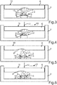
- Fig. 1 shows a first example of an operating device.
- the operating device has a housing which forms a basic element 1.
- An alternative basic element 1 could be a simple base plate.
- the housing or basic element 1 serves as a carrier for a transceiver device 2. This is firmly connected to the basic element 1.
- the transceiver 2 has a transmitting part 3 and a receiving part 4.
- the transmitting part 3 and the receiving part 4 are housed together in a sensor housing 5 of the transceiver 2.
- the operating device has an operating element 6.
- This operating element 6 is, for example, a touch element that can be pressed down with the finger.
- the control element 6 can therefore be moved relative to the base element 1.
- the basic element 1 or the control element 6 has, for example, a corresponding linear guide. This can be realized by walls of the housing or basic element 1.
- Fig. 1 shows the control element 6 in relation to the base element 1 in a first extreme position, here in particular in a position in which the control element 6 is the most distant from the base element 1.
- the control element 6 has an optical element 8, which in the present example is designed as a concave, symmetrical reflector.
- the optical element 8 is integrated directly into the control element 6 here.
- the optical element 8 could also be attached to the control element 6 as a separate element.
- the light of the transmitting part 3 is radiated onto the optical element 8 in such a way and at the same time the optical element 8 is designed (in particular geometrically) such that the light 7 is focused in a plane A.
- a corresponding focal point 9 is formed. This lies here within the transceiver 2 and in particular just below the receiving part 4.
- Fig. 2 if the control element 6 moves towards the base element 1 in accordance with an actuation direction 10, its relative position with respect to the base element 1 changes Fig. 1 the control element 6 assumes a first extreme position 10, which corresponds here to the non-actuated position of the control device.
- the control element 6 assumes a second extreme position 11, which corresponds to an actuation position.
- the control element 6 can only be moved between these two extreme positions 10 and 11. So that the extreme positions 10 and 11 are not exceeded, corresponding stops are provided, which are not shown in the figures.
- a force 12 acts in the actuating direction, for example, through a finger.
- the focus 9 also moves from the plane A into the plane B.
- This plane B which runs parallel to plane A and is also oriented perpendicular to the actuation direction or force 12, is closer to the bottom 13 of the base element 1 than plane A.
- plane B lies further from the receiving part 4 removed as the plane A. Because of the second extreme position 11 of the control element 6 or the optical element 8, a new focus 9 'results on the plane B. This new focus 9' also lies within the transceiver 2 directly below the receiving part 4 .
- the evaluation device can immediately decide in which position the control element 6 is located. If necessary, the path between the two extreme positions 10 and 11 can even be determined on the basis of the decrease in intensity.
- FIGS 1 and 2 a second example of an operating device is shown schematically.
- the individual components correspond essentially in their type, in their structure and in their functioning to those of the first embodiment according to FIGS 1 and 2 .
- Only the optical element 8 'or the radiation of the light 7 from the transmitting part 3 is directed or bundled in such a way that a focus 13 is formed in a plane A' in the vicinity of the receiving part 4.
- Level A ' is located outside of the transceiver 2 and in particular above the receiving part 4, that is between the receiving part 4 and the operating element 6. This applies to the first extreme position 10.
- the evaluation device can clearly derive the position of the operating element 6 relative to the basic element 1 from the intensity of the light incident on the receiving part 4.
- the 5 and 6 show an embodiment of the control device according to the invention.
- the structure of the operating device is essentially the same as that of the operating device according to FIGS 1 and 2 .
- the optical element 8 ′′ is in or on the control element 6 with respect to that in FIGS 5 and 6 shown cutting plane is asymmetrical.
- the optical element 8 "is also concave and focusing here, but due to its asymmetry, the focal point moves perpendicular to the actuating direction of the operating element 6 or the force 12 exerted thereon.
- there is a focus 14 of the one deflected and focused by the optical element 8" Light 7 in a plane A "when the control element 6 is in the first extreme position 10 (non-actuation position).
- the plane A" here runs parallel to the predefined actuation direction of the control element 6, here parallel to the force 12.
- the plane lies A "outside the transceiver 2.
- the focal point 14 ′ here lies within the transceiver 2.
- the focal point 14 ′ is closer to the receiving part 4 than the focal point 14. Accordingly, the light intensity at or in the receiving part 4 is also higher when the operating element 6 is in the second extreme position 11 compared to the case that the control element 6 is in the first extreme position 10 and the focal point 14 is accordingly outside the transceiver 2.
- an actuation of the control element 6 is converted into a displacement of the focal point perpendicular to it. Nevertheless, the position of the control element 6 can also be clearly recognized here by the respective intensity of the light on the receiving part. The same applies if the focal point shifts obliquely to the direction of actuation when the control element 6 is actuated.
- the focal point is closer to the receiving part 4 in an extreme position of the control element than in the second extreme position of the control element. It would be disadvantageous if the focal point passes through the receiving part 4 when the control element 6 moves from one extreme position 10 to the other extreme position 11. In this case, the control element 6 could assume two different positions with the same light intensity. In the extreme case, the focal point could be in one of the two extreme positions in or on the receiving part 4 so that the position of the control element 6 can still be clearly determined. For reasons of tolerance, however, it is preferable that the focal point is always outside the receiving part 4.
Landscapes
- Engineering & Computer Science (AREA)
- Physics & Mathematics (AREA)
- General Physics & Mathematics (AREA)
- General Engineering & Computer Science (AREA)
- Theoretical Computer Science (AREA)
- Human Computer Interaction (AREA)
- Photo Coupler, Interrupter, Optical-To-Optical Conversion Devices (AREA)
- Switches Operated By Changes In Physical Conditions (AREA)
Description
- Die vorliegende Erfindung betrifft eine Bedienvorrichtung mit einem Grundelement, einer Sende-Empfangseinrichtung, die fest an dem Grundelement angeordnet ist, zum Aussenden und Empfangen von Licht, einem Bedienelement, das gegenüber dem Grundelement zwischen einer ersten Extremstellung und einer zweiten Extremstellung bewegbar ist, und einem Optikelement, das fest an dem Bedienelement angeordnet ist, zum Umlenken des Lichts der Sende-Empfangseinrichtung. Darüber hinaus betrifft die vorliegende Erfindung eine Fahrzeugbedienanordnung mit einer derartigen Bedienvorrichtung.
- Die
GB 2465372 A - Die
US 5,943,233 offenbart ein Eingabemittel mit einem optischen Sensor des Reflektionstypes, welcher eine Lichtquelle, einen Lichtsensor und einen Betätigungsbereich aufweist. Der Betätigungsbereich ist schwenkbar und das Maß der Schwenkung durch den Sensor ermittelbar. - Die
US 2011/0221707 A1 offenbart ein Display dessen Frontseite betätigbar ist. Dazu ist die Frontseite schwenkbar gelagert, so dass ein Teil des Hintergrundlichtes über Reflektoren einem Lichtsensor zugeführt wird. Damit kann die Betätigung der Frontseite erkannt werden. - Aus der Druckschrift
US 2014/0098065 A1 sind ein Touch-Screen-System und ein entsprechendes Verfahren zur Erfassung einer Touch-Screen-Verlagerung bekannt. Eine Sendeeinrichtung strahlt Licht an die Rückseite des Touch-Screens. Dort wird das Licht reflektiert und trifft auf einen optischen Empfänger. Wird der Touch-Screen betätigt, ändert sich der Abstand der Bedienfläche zu der optischen Sendeeinrichtung und der optischen Empfangseinrichtung. Die aufgebrachte Kraft an der Bedienoberfläche kann mittels der sich ändernden Lichtintensität durch die hervorgerufene Abstandsänderung gemessen werden. - Die Druckschrift
US 2015/0242056 A1 offenbart ein Gerät und ein Verfahren zur Detektion von Oberflächenscherkräften auf einer Anzeigevorrichtung. Die Anzeigevorrichtung weist ein Pixelarray mit einer Vielzahl an Pixeln, eine Vielzahl an Infrarotemittern, die Licht an eine Oberfläche der Anzeigevorrichtung emittieren, eine Vielzahl an IR-Detektoren zum Detektieren des IR-Lichts, eine deformierbare Schicht an der Oberfläche der Anzeigevorrichtung und eine Vielzahl an Reflektoren an der deformierbaren Schicht, um das IR-Licht zu den IR-Detektoren zu reflektieren, auf. Es soll eine Bewegung eines Eingabemittels auf einer Bedienoberfläche mittels der IR-Emitter und IR-Detektoren erkannt werden. Das Messprinzip beruht auf der Intensität. - Die Änderung der Entfernung eines Reflektors mithilfe optischer Reflexionslichtschranken zur Bestimmung ist also bekannt. Die Auflösung der Änderung der Entfernung ist aber nicht besonders hochwertig. Für eine Erkennung eines geschalteten Zustands oder einer Krafterkennung bei Schaltern ist jedoch eine besonders hohe Auflösung der Entfernungsänderung nötig.
- Die Aufgabe der vorliegenden Erfindung besteht somit darin, eine Bedienvorrichtung auf optischer Basis bereitzustellen, bei der eine Änderung einer Stellung eines Bedienelements mit verbesserter Auflösung detektierbar ist.
- Erfindungsgemäß wird diese Aufgabe durch eine Bedienvorrichtung nach Anspruch 1 gelöst. Vorteilhafte Weiterbildungen der Erfindung ergeben sich aus den Unteransprüchen.
- Es wird somit eine Bedienvorrichtung mit einem Grundelement und einer Sende-Empfangseinrichtung, die fest an dem Grundelement angeordnet ist, zum Aussenden und Empfangen von Licht bereitgestellt. Eine derartige Bedienvorrichtung kann beispielsweise für einen Schalter, einen Weglängensensor, einen Touchscreen oder dergleichen verwendet werden. Die Bedienvorrichtung besitzt ein Grundelement, das beispielsweise als Träger, Gehäuse oder dergleichen ausgebildet sein kann. An dem Grundelement ist die Sende-Empfangseinrichtung, z.B. ein IR-Sende-Empfangschip, befestigt. Damit ist die Sende-Empfangseinrichtung ortsfest mit dem Grundelement verbunden. Weiterhin besitzt die Bedienvorrichtung ein Bedienelement, das gegenüber dem Grundelement zwischen einer ersten Extremstellung und einer zweiten Extremstellung bewegbar ist. Bei betriebsgemäßer Bedienung ist also vorgesehen, dass beispielsweise bei NichtBetätigung das Bedienelement die erste Extremstellung einnimmt und bei einer hinreichend starken Betätigung die zweite Extremstellung. So wird beispielsweise die Schalteroberfläche von einer Ausgangsstellung in eine Endstellung bewegt, wenn der Schalter betätigt wird. Dabei findet also eine Relativbewegung zwischen dem Bedienelement und dem Grundelement statt. In der Regel wird es sich hierbei um eine lineare Bewegung handeln.
- Ein Optikelement, das fest an dem Bedienelement angeordnet ist, dient zum Umlenken des Lichts der Sende-Empfangseinrichtung. Das Optikelement kann beispielsweise das Licht des Sendeelements der Sende-Empfangseinrichtung zu deren Empfangselement reflektieren. Dabei ist das Optikelement fest mit dem Bedienelement verbunden beziehungsweise in dieses integriert. Dies bedeutet, dass das Optikelement gegenüber dem Grundelement bei dem Betätigen die gleiche Bewegung vollzieht. Diese Bewegung des Optikelements wirkt sich auch auf das Umlenken des Lichts aus.
- Durch das Optikelement ist das Licht der Sende-Empfangseinrichtung im Wesentlichen in Richtung auf ein Empfangsteil der Sende-Empfangseinrichtung fokussierbar. Beispielsweise sendet das Sendeteil der Sende-Empfangseinrichtung divergentes Licht aus. Dieses divergente Licht trifft auf das Optikelement, welches das Licht auf dem Empfangsteil der Sende-Empfangseinrichtung fokussiert. Dies bedeutet, dass vorzugsweise der größte Teil des von dem Optikelement umgelenkten Lichts in mindestens einer der Extremstellungen des Bedienelements auf den Empfangsteil der Sende-Empfangseinrichtung trifft. Der tatsächliche Ort des Fokus hängt von der Stellung des Optikelements ab und liegt vorzugsweise in unmittelbarer Nähe des Empfangsteils beziehungsweise in dem Empfangsteil.
- Darüber hinaus besitzt die Bedienvorrichtung eine Auswerteeinrichtung zum Auswerten eines Signals des Empfangsteils, wobei die Auswerteeinrichtung derart ausgebildet ist, dass einer Intensität des empfangenen Lichts, die durch das Signal repräsentiert wird, eine Stellung des Bedienelements in einem Bereich von der ersten Extremstellung zu der zweiten Extremstellung zugeordnet wird. Es wird also in Abhängigkeit von dem empfangenen optischen Signal auf die Stellung beziehungsweise Position des Bedienelements geschlossen. Da sich das Bedienelement von der ersten Extremstellung zur zweiten Extremstellung beziehungsweise umgekehrt bewegen kann, ändert sich entsprechend auch die Lichtintensität des Lichts, welches in Richtung auf das Empfangsteil fokussiert ist. Entsprechend der Bewegung ändert sich der Fokus des Lichts und damit auch an der Stelle des Empfangsteils die Intensität des Lichts. Auf diese Weise kann sehr genau auf die Position des Bedienelements geschlossen werden. Insbesondere kann nicht nur die jeweilige Extremstellung zweifelsfrei erkannt werden, sondern in Abhängigkeit von der Intensitätsänderung des Lichts auch entsprechende Zwischenstellungen je nach Auflösung.
- Vorzugsweise wird das Optikelement durch einen konkaven Abschnitt des Bedienelements gebildet. Das Bedienelement besitzt also einen konkaven Abschnitt, der günstigerweise unmittelbar in das Bedienelement eingearbeitet ist. Der konkave Abschnitt kann aber auch durch ein separates Element gebildet werden, das an dem Bedienelement fixiert ist. Der konkave Abschnitt besitzt die optische Eigenschaft, Licht zu bündeln beziehungsweise zu fokussieren. Vorzugsweise ist der konkave Abschnitt hinsichtlich seiner Oberflächengeometrie derart optimiert, dass sich eine hochwertige Fokussierung ergibt. Damit erfüllt das Bedienelement eine doppelte Funktionalität, nämlich die des Betätigtwerdens, aber auch die des Umlenkens beziehungsweise Fokussierens des Lichts der Sende-Empfangseinrichtung.
- In einer weiteren Ausgestaltung kann vorgesehen sein, dass ein jeweiliger Brennpunkt des Lichts in jeder der beiden Extremstellungen des Bedienelements außerhalb der Sende-Empfangseinrichtung liegt. Dabei ist vorzuziehen, dass der Brennpunkt des Lichts bezüglich des Empfangsteils der Sende-Empfangseinrichtung immer auf einer Seite liegt. Wenn andernfalls der Fokus nämlich bei seiner Wanderung, die sich aus der Bewegung des Bedienelements beziehungsweise Optikelements von der ersten Extremstellung in die zweite Extremstellung ergibt, das Empfangsteil durchkreuzt oder von einer Seite des Empfangsteils zur anderen Seite gelangt, ist die Auswertung der Intensität nicht mehr eindeutig auf die Stellung des Bedienelements zu beziehen. Daher sollte der Brennpunkt günstigerweise bei seiner Bewegung nicht den Empfangsteil durchlaufen und dabei ein Intensitätsmaximum liefern. Vielmehr ist bei der Bewegung des Bedienelements beziehungsweise des Brennpunkts wünschenswert, wenn die Intensität stetig zu- oder abnimmt.
- In einer alternativen Ausführungsform kann vorgesehen sein, dass ein jeweiliger Brennpunkt des Lichts in jeder der beiden Extremstellungen des Bedienelements innerhalb der Sende-Empfangseinrichtung liegt. Wenn der jeweilige Brennpunkt stets innerhalb der Sende-Empfangseinrichtung liegt, befindet er sich stets sehr nahe an dem Empfangsteil der Sende-Empfangseinrichtung. Diese bedeutet, dass eine gute Fokussierung vorliegt und daher mit einem entsprechend hohen Intensitätssignal in jeder Stellung des Bedienelements zu rechnen ist.
- In einer weiteren Ausgestaltung kann vorgesehen sein, dass das Optikelement derart gestaltet ist und das von der Sende-Empfangseinrichtung ausgesandte Licht derart auf das Optikelement gerichtet ist, dass sich ein Brennpunkt bei einem Bewegen des Bedienelements in einer Betätigungsrichtung mit einer Bewegungskomponente parallel zu dieser Betätigungsrichtung bewegt. Dies bedeutet beispielsweise, wenn das Betätigungselement senkrecht nach unten bewegt wird, dann wandert mit dieser Bewegung auch der Brennpunkt senkrecht nach unten. Der Brennpunkt muss sich aber nicht zwangsläufig in der gleichen Richtung beziehungsweise parallel zu der Betätigungsrichtung bewegen. Vielmehr genügt es, wenn von der Bewegungsrichtung des Brennpunkts zumindest eine Komponente (d.h. Vektorkomponente) parallel zu Betätigungsrichtung verläuft. D.h. bei einer Betätigungsrichtung senkrecht nach unten kann sich der Brennpunkt auch schräg nach unten bewegen.
- Erfindungsgemäß ist vorgesehen, dass das Optikelement derart asymmetrisch gestaltet und das von der Sende-Empfangseinrichtung ausgesandte Licht derart auf das Optikelement gerichtet ist, dass sich ein Brennpunkt bei einem Bewegen des Bedienelements in einer Betätigungsrichtung mit einer Bewegungskomponente senkrecht zu dieser Betätigungsrichtung bewegt. In diesem Fall kann sich der Brennpunkt beispielsweise ausschließlich senkrecht zu der Betätigungsrichtung des Bedienelements bewegen. In der Regel wird es aber so sein, dass sich der Brennpunkt nicht nur senkrecht zu der Betätigungsrichtung bewegt, sondern auch mit einer Teilkomponente in Richtung der Betätigungsrichtung. Damit ergäbe sich wieder eine schräge Bewegung des Brennpunkts in Bezug auf die Bewegung des Bedienelements. Eine derartige Bewegungskomponente senkrecht zu der Betätigungsrichtung kann erfindungsgemäß dadurch erreicht werden, dass das Optikelement asymmetrisch gestaltet ist. Beispielsweise kann das Optikelement die Negativform eines halben Tropfens besitzen. Gleichzeitig ist es dabei von Vorteil, wenn das Optikelement asymmetrisch bezüglich der Hauptabstrahlrichtung des Sendeteils der Sende-Empfangseinrichtung angeordnet ist. Beispielsweise kann sich der Brennpunkt in einer ersten Extremstellung des Bedienelements innerhalb des Empfangsteils und in der zweiten Extremstellung des Bedienelements außerhalb des Empfangsteils der Sende-Empfangseinrichtung befinden. Durch dieses Wandern des Brennpunkts senkrecht zu der Betätigungsrichtung kann eine sehr hohe Ortsauflösung erreicht werden.
- Vorzugsweise handelt es sich bei dem Optikelement um einen Reflektor. Mit einem solchen Reflektor ist es einfacher realisierbar, das von dem Sendeteil der Sende-Empfangseinrichtung ausgesandte Licht auf das Empfangsteil zu reflektieren. Wenn Sende- und Empfangsteil beispielsweise auf einem Chip sehr nahe beieinander liegen, wird das Licht durch den Reflektor praktisch zurück reflektiert. Es handelt sich dann praktisch um eine Bedienvorrichtung mit Reflexionslichtschranke, wobei der Reflektor bewegbar ist.
- In einer weiteren Ausgestaltung weist die Sende-Empfangseinrichtung an einer Seite gemeinsam ein Sendeteil zum Aussenden des Lichts und das Empfangsteil zum Empfangen des Lichts auf. Dies bedeutet, dass sowohl Sendeteil als auch Empfangsteil bei einer beispielsweise quaderförmigen Sende-Empfangseinrichtung sich auf ein und derselben Seite der Sende-Empfangseinrichtung befinden. Insbesondere ist dies bei sogenannten Einchiplösungen vorteilhaft. Sowohl Sendeteil als auch Empfangsteil sind dabei vorteilhaft direkt auf das Optikelement beziehungsweise das Bedienelement gerichtet.
- Ein weiteres Ausführungsbeispiel einer Bedienvorrichtung kann dahingehend gestaltet sein, dass die Auswerteeinrichtung dazu ausgebildet ist, das Signal des Empfangsteils zwei vorgegebenen Stellungen des Bedienelements binär zuzuordnen. Vorzugsweise handelt es sich bei den zwei vorgegebenen Stellungen um die beiden Extremstellungen. Auf diese Weise kann ein sicherer Ein-/Ausschalter realisiert werden.
- Des Weiteren kann vorgesehen sein, dass die Auswerteeinrichtung dazu ausgebildet ist, das Signal des Empfangsteils kontinuierlich einer jeweiligen Stellung des Bedienelements in dem Bereich von der ersten Extremstellung zu der zweiten Extremstellung zuzuordnen. Damit lässt sich nicht nur ein binärer Schalter realisieren, sondern eine kontinuierliche Einstellung vornehmen. Beispielsweise ist eine derartige kontinuierliche Einstellung für eine Beleuchtung oder einen Fensterheber im Kraftfahrzeug von Vorteil.
- Wie oben bereits angedeutet wurde, kann eine Fahrzeugbedienanordnung mit der oben beschriebenen Bedienvorrichtung ausgestattet sein. Es lässt sich damit eine Fahrzeugbedienanordnung realisieren, die optisch zuverlässig auswertbar ist. Insbesondere ergibt sich dabei eine hohe Störsicherheit. Darüber hinaus kann gegebenenfalls auch eine hohe Auflösung für die Fahrzeugbedienanordnung erreicht werden.
- Weitere Merkmale der Erfindung ergeben sich aus den Ansprüchen, den Figuren und der Figurenbeschreibung. Die vorstehend in der Beschreibung genannten Merkmale und Merkmalskombinationen sowie die nachfolgend in der Figurenbeschreibung genannten und/oder in den Figuren alleine gezeigten Merkmale und Merkmalskombinationen sind nicht nur in der jeweils angegebenen Kombination, sondern auch in anderen Kombinationen verwendbar, ohne den Rahmen der Erfindung zu verlassen. Es sind somit auch Ausführungen von der Erfindung als umfasst und offenbart anzusehen, die in den Figuren nicht explizit gezeigt und erläutert sind, jedoch durch separierte Merkmalskombinationen aus den erläuterten Ausführungen hervorgehen und erzeugbar sind. Es sind auch Ausführungen und Merkmalskombinationen als offenbart anzusehen, die somit nicht alle Merkmale eines ursprünglich formulierten unabhängigen Anspruchs aufweisen. Es sind darüber hinaus Ausführungen und Merkmalskombinationen, insbesondere durch die oben dargelegten Ausführungen, als offenbart anzusehen, die über die in den Rückbezügen der Ansprüche dargelegten Merkmalskombinationen hinausgehen oder von diesen abweichen.
- Die vorliegende Erfindung wird nun anhand der beigefügten Zeichnungen näher erläutert, in denen zeigen:
-
Fig. 1 eine Bedienvorrichtung gemäß einem ersten Beispiel in einem unbetätigten Zustand; -
Fig. 2 die Bedienvorrichtung vonFig. 1 im betätigten Zustand; -
Fig. 3 eine Bedienvorrichtung gemäß einem zweiten Beispiel im unbetätigten Zustand; -
Fig. 4 die Bedienvorrichtung vonFig. 3 im betätigten Zustand; -
Fig. 5 eine Bedienvorrichtung gemäß einem Ausführungsbeispiel der Erfindung im unbetätigten Zustand; und -
Fig. 6 die Bedienvorrichtung vonFig. 5 im betätigten Zustand. - Wie eingangs erwähnt wurde, ist bekannt, die Änderung der Entfernung eines Reflektors mithilfe optischer Reflexionslichtschranken zu bestimmen. Die Auflösung der Änderung der Entfernung ist bei diesem Prinzip nur grob. Für die Erkennung eines geschalteten Zustands oder einer Krafterkennung bei Schaltern ist jedoch eine höhere Auflösung notwendig. Hierzu ist die vorliegende Erfindung hilfreich.
- Die Erfindung basiert auf der Idee, dass eine Fokussierung von ausgesandtem Licht abhängig von einer Position eines Reflektors eine große Änderung der Lichtmenge auf einem Sensor hervorruft. Dabei kann es sinnvoll sein, die Geometrie einer zumindest teilweise spiegelnden Oberfläche eines Reflektors entsprechend auszugestalten. Der Brennpunkt kann beispielsweise in verschiedene Richtungen wandern (horizontal und/oder vertikal). Damit erreicht man eine höhere Auflösung bei gegebener Wegänderung.
- Beispielsweise kann bei einer Bedienvorrichtung mit einem Bedienelement und einer Grundplatte ersteres relativ zu zweiterer bewegt werden. Die Betätigung wird über die entsprechende Abstandsänderung detektiert, wobei die Detektion über einen optischen Sensor mit Sender und Empfänger erfolgt. Der optische Sensor ist in diesem Beispiel an der Grundplatte angebracht und sendet Licht in Richtung der Bedienoberfläche aus, an welcher das Licht zum Empfänger des Sensors zurückreflektiert wird. Dazu ist das Bedienelement derart gestaltet, dass der Brennpunkt des zurückreflektierten Lichts bei Null-Stellung oder Betätigungsstellung im Bereich des Empfängers liegt. Der Abstand des Brennpunkts von dem Empfangsteil sollte nicht größer sein als des Empfangsteil selbst.
-
Fig. 1 zeigt ein erstes Beispiel einer Bedienvorrichtung. Die Bedienvorrichtung weist in dem vorliegenden Beispiel ein Gehäuse auf, das ein Grundelement 1 bildet. Ein alternatives Grundelement 1 könnte eine einfache Grundplatte sein. Das Gehäuse beziehungsweise Grundelement 1 dient als Träger für eine Sende-Empfangseinrichtung 2. Diese ist fest mit dem Grundelement 1 verbunden. Die Sende-Empfangseinrichtung 2 besitzt ein Sendeteil 3 und ein Empfangsteil 4. Beispielsweise sind das Sendeteil 3 und das Empfangsteil 4 gemeinsam in einem Sensorgehäuse 5 der Sende-Empfangseinrichtung 2 untergebracht. - Weiterhin besitzt die Bedienvorrichtung ein Bedienelement 6. Dieses Bedienelement 6 ist beispielsweise ein Tastelement, welches mit dem Finger herabgedrückt werden kann. Das Bedienelement 6 ist also relativ zu dem Grundelement 1 bewegbar. Dazu besitzt das Grundelement 1 beziehungsweise das Bedienelement 6 beispielsweise eine entsprechende Linearführung. Diese kann durch Wände des Gehäuses beziehungsweise Grundelements 1 realisiert sein.
Fig. 1 zeigt das Bedienelement 6 gegenüber dem Grundelement 1 in einer ersten Extremstellung, hier insbesondere in einer Stellung, in der das Bedienelement 6 von dem Grundelement 1 am weitesten entfernt ist. - Die Sende-Empfangseinrichtung 2 mit einer in den Fig. nicht näher dargestellten Auswerteeinrichtung, die ebenfalls in das Sensorgehäuse 5 integriert sein kann, wird die Position beziehungsweise Stellung des Bedienelements 6 relativ zu dem Grundelement 1 beziehungsweise der Sende-Empfangseinrichtung 2 bestimmen. Dies geschieht dadurch, dass das Sendeteil 3 der Sende-Empfangseinrichtung 2 Licht 7 aussendet, welches von dem Bedienelement 6 in Richtung auf das Empfangsteil 4 umgelenkt und fokussiert wird. Dazu besitzt das Bedienelement 6 ein Optikelement 8, welches im vorliegenden Beispiel als konkaver, symmetrischer Reflektor ausgebildet ist. Das Optikelement 8 ist hier unmittelbar in das Bedienelement 6 integriert. Alternativ könnte das Optikelement 8 auch auf dem Bedienelement 6 als eigenes Element befestigt sein.
- In dem Beispiel von
Fig. 1 wird das Licht des Sendeteils 3 derart auf das Optikelement 8 gestrahlt und gleichzeitig ist das Optikelement 8 derart gestaltet (insbesondere geometrisch), dass das Licht 7 in einer Ebene A fokussiert wird. Es bildet sich ein entsprechender Brennpunkt 9. Dieser liegt hier innerhalb der Sende-Empfangseinrichtung 2 und insbesondere knapp unter dem Empfangsteil 4. - Wird nun gemäß
Fig. 2 das Bedienelement 6 entsprechend einer Betätigungsrichtung 10 auf das Grundelement 1 zu bewegt, so verändert sich seine relative Stellung gegenüber dem Grundelement 1. InFig. 1 nimmt das Bedienelement 6 eine erste Extremstellung 10 ein, was hier der Nicht-Betätigungsstellung der Bedienvorrichtung entspricht. InFig. 2 hingegen nimmt das Bedienelement 6 eine zweite Extremstellung 11 ein, die einer Betätigungsstellung entspricht. Das Bedienelement 6 lässt sich nur zwischen diesen beiden Extremstellungen 10 und 11 bewegen. Damit die Extremstellungen 10 und 11 nicht überschritten werden, sind entsprechende Anschläge vorgesehen, die in den Fig. nicht dargestellt sind. In der zweiten Extremstellung 11 wirkt beispielsweise durch einen Finger eine Kraft 12 in Betätigungsrichtung. Aufgrund der Bewegung des Bedienelements in die zweite Extremstellung 11 wandert auch der Fokus 9 von der Ebene A in die Ebene B. Diese Ebene B, die parallel zu der Ebene A verläuft und darüber hinaus senkrecht zu der Betätigungsrichtung beziehungsweise der Kraft 12 ausgerichtet ist, liegt näher an dem Boden 13 des Grundelements 1 als die Ebene A. Gleichzeitig liegt die Ebene B weiter von dem Empfangsteil 4 entfernt als die Ebene A. Aufgrund der zweiten Extremstellung 11 des Bedienelements 6 beziehungsweise des Optikelements 8 ergibt sich demzufolge ein neuer Fokus 9' auf der Ebene B. Auch dieser neue Fokus 9' liegt innerhalb der Sende-Empfangseinrichtung 2 direkt unterhalb des Empfangsteils 4. - Es ist sofort zu erkennen, dass die Lichtintensität in der ersten Extremstellung 10 des Bedienelements 6 gemäß
Fig. 1 auf beziehungsweise im Empfangsteil 4 größer ist als die Intensität des Lichts 7 in der zweiten Extremstellung 11 gemäßFig. 2 . Dies liegt daran, dass der Fokus 9 in der ersten Extremstellung 10 näher an dem Empfangsteil 4 liegt als der Fokus 9' in der zweiten Extremstellung 11. Aufgrund dieses Intensitätsunterschieds kann die Auswerteeinrichtung sofort entscheiden, in welcher Stellung sich das Bedienelement 6 befindet. Gegebenenfalls kann sogar der Weg zwischen den beiden Extremstellungen 10 und 11 aufgrund der Intensitätsabnahme festgestellt werden. - In den
Fig. 3 und 4 ist ein zweites Beispiel einer Bedienvorrichtung schematisch wiedergegeben. Die einzelnen Komponenten entsprechen in ihrer Art, in ihrem Aufbau und in ihrer Funktionsweise im Wesentlichen denen der ersten Ausführungsform gemäß denFig. 1 und 2 . Es ist lediglich das Optikelement 8' beziehungsweise die Abstrahlung des Lichts 7 von Sendeteil 3 derart gerichtet beziehungsweise gebündelt, dass sich in der Nähe des Empfangsteils 4 ein Fokus 13 in einer Ebene A' bildet. Die Ebene A' befindet sich außerhalb der Sende-Empfangseinrichtung 2 und insbesondere oberhalb des Empfangsteils 4, also zwischen Empfangsteil 4 und Bedienelement 6. Dies gilt für die erste Extremstellung 10. - In der zweiten Extremstellung 11 gemäß
Fig. 4 , in der das Bedienelement 6 mit einer Kraft 12 in gleichgerichteter Betätigungsrichtung bewegt ist, ergibt sich ein Fokus 13' in einer Ebene B'. Diese Ebene B', die parallel zu der Ebene A' verläuft, steht wiederum senkrecht auf der Betätigungsrichtung beziehungsweise der Kraft 12. Der Brennpunkt 13' liegt ebenfalls außerhalb der Sende-Empfangseinrichtung 2 und insbesondere oberhalb des Empfangsteils 4. Er befindet sich also auch zwischen der Sende-Empfangseinrichtung 2 und dem Bedienelement 6. Der Fokus 13 wandet in Betätigungsrichtung auf den Fokus 13', wenn das Bedienelement 6 von der ersten Extremstellung 10 in die zweite Extremstellung 11 bewegt wird. - In diesem Fall ist zu erkennen, dass das Licht 7 umgelenkt durch das Optikelement 8' dann eine höhere Intensität besitzt, wenn sich das Bedienelement 6 in der zweiten Extremstellung befindet und damit der Brennpunkt 13' näher an dem Empfangsteil 4 liegt als der Brennpunkt 13 bei der ersten Extremstellung 10. Auch hier kann die Auswerteeinrichtung die Stellung des Bedienelements 6 relativ zu dem Grundelement 1 klar von der Intensität des auf das Empfangsteil 4 einfallenden Lichts ableiten.
- Die
Fig. 5 und 6 zeigen ein Ausführungsbeispiel der erfindungsgemäßen Bedienvorrichtung. Wiederum ist der Aufbau der Bedienvorrichtung im Wesentlichen gleich demjenigen der Bedienvorrichtung gemäß denFig. 1 und 2 . Hier ist allerdings das Optikelement 8" in beziehungsweise an dem Bedienelement 6 bezüglich der in denFig. 5 und 6 dargestellten Schnittebene asymmetrisch ausgebildet. Das Optikelement 8" ist zwar auch hier konkav und fokussierend ausgebildet, aber durch dessen Asymmetrie bewegt sich der Brennpunkt senkrecht zu der Betätigungsrichtung des Bedienelements 6 beziehungsweise der darauf ausgeübten Kraft 12. Konkret befindet sich ein Fokus 14 des von dem Optikelement 8" umgelenkten und fokussierten Lichts 7 in einer Ebene A", wenn sich das Bedienelement 6 in der ersten Extremstellung 10 (Nicht-Betätigungsstellung) befindet. Die Ebene A" verläuft hier parallel zu der vorgegebenen Betätigungsrichtung des Bedienelements 6, hier parallel zur Kraft 12. Außerdem liegt die Ebene A" außerhalb der Sende-Empfangseinrichtung 2. - Wird nun die Bedienvorrichtung mit einer Kraft 12 in selbiger Richtung betätigt, so verschiebt sich der Fokus auf den neuen Brennpunkt 14', der in Ebene B" liegt. Die Ebene B" ist parallel zu der Ebene A" und ebenfalls parallel zu der Kraft 12 beziehungsweise Betätigungsrichtung. Ferner liegt der Brennpunkt 14' hier innerhalb der Sende-Empfangseinrichtung 2.
- Es ist zu erkennen, dass der Brennpunkt 14' näher an dem Empfangsteil 4 liegt als der Brennpunkt 14. Demzufolge ist auch die Lichtintensität an beziehungsweise in dem Empfangsteil 4 höher, wenn sich das Bedienelement 6 in der zweiten Extremstellung 11 befindet gegenüber dem Fall, dass sich das Bedienelement 6 in der ersten Extremstellung 10 und der Brennpunkt 14 entsprechend außerhalb der Sende-Empfangseinrichtung 2 befindet. In diesem Beispiel wird also eine Betätigung des Bedienelements 6 in eine dazu senkrechte Verschiebung des Brennpunkts umgesetzt. Trotzdem lässt sich auch hier die Stellung des Bedienelements 6 eindeutig an der jeweiligen Intensität des Lichts an dem Empfangsteil erkennen. Ähnliches gilt, wenn sich bei Betätigung des Bedienelements 6 der Brennpunkt schräg zu der Betätigungsrichtung verschiebt. Für eine eindeutige Zuordnung der Intensität zu einer Stellung des Bedienelements ist es allgemein von Vorteil, wenn der Brennpunkt in einer Extremstellung des Bedienelements näher an dem Empfangsteil 4 liegt als in der zweiten Extremstellung des Bedienelements. Nachteilig wäre, wenn der Brennpunkt das Empfangsteil 4 durchwandert, wenn sich das Bedienelement 6 von der einen Extremstellung 10 in die andere Extremstellung 11 bewegt. In diesem Fall könnte das Bedienelement 6 bei gleicher Lichtintensität zwei verschiedene Stellungen einnehmen. Im Extremfall könnte also allenfalls der Brennpunkt in einer der beiden Extremstellungen in beziehungsweise auf dem Empfangsteil 4 liegen, damit die Position des Bedienelements 6 noch eindeutig bestimmt werden kann. Aus Toleranzgründen ist es aber vorzuziehen, dass der Brennpunkt stets außerhalb des Empfangsteils 4 liegt.
Claims (9)
- Bedienvorrichtung mit- einem Grundelement (1),- einer Sende-Empfangseinrichtung, die fest an dem Grundelement (1) angeordnet ist, zum Aussenden und Empfangen von Licht (7),- einem Bedienelement (6), das gegenüber dem Grundelement (1) zwischen einer ersten Extremstellung (10) und einer zweiten Extremstellung (11) bewegbar ist, und- einem Optikelement (8), das fest an dem Bedienelement (6) angeordnet ist, zum Umlenken des Lichts (7) der Sende-Empfangseinrichtung,wobei- durch das Optikelement (8) das Licht (7) der Sende-Empfangseinrichtung im Wesentlichen in Richtung auf ein Empfangsteil (4) der Sende-Empfangseinrichtung fokussierbar ist und- eine Auswerteeinrichtung der Bedienvorrichtung zum Auswerten eines Signals des Empfangsteils (4) derart ausgebildet ist, dass eine Intensität des empfangenen Lichts (7), die durch das Signal repräsentiert wird, einer Stellung des Bedienelements (6) in einem Bereich von der ersten Extremstellung (10) bis zu der zweiten Extremstellung (11) zugeordnet wird, dadurch gekennzeichnet, dass- das Optikelement (8) derart asymmetrisch gestaltet und das von der Sende-Empfangseinrichtung ausgesandte Licht (7) derart auf das Optikelement (8) gerichtet ist, dass sich ein Brennpunkt (14) bei einem Bewegen des Bedienelements (6) in einer Betätigungsrichtung (12) mit einer Bewegungskomponente senkrecht zu dieser Betätigungsrichtung (12) bewegt.
- Bedienvorrichtung nach Anspruch 1,
dadurch gekennzeichnet, dass
das Optikelement (8) durch einen konkaven Abschnitt des Bedienelements (6) gebildet ist. - Bedienvorrichtung nach Anspruch 1 oder 2,
dadurch gekennzeichnet, dass
ein jeweiliger Brennpunkt (14) des Lichts (7) in jeder der beiden Extremstellungen (10, 11) des Bedienelements (6) außerhalb des Empfangsteils (4) der Sende-Empfangseinrichtung liegt. - Bedienvorrichtung nach Anspruch 1 oder 2,
dadurch gekennzeichnet, dass
ein jeweiliger Brennpunkt (14) des Lichts (7) in jeder der beiden Extremstellungen (10, 11) des Bedienelements (6) innerhalb der Sende-Empfangseinrichtung liegt. - Bedienvorrichtung nach einem der vorhergehenden Ansprüche, dadurch gekennzeichnet, dass
das Optikelement (8) einen Reflektor aufweist. - Bedienvorrichtung nach einem der vorhergehenden Ansprüche, dadurch gekennzeichnet, dass
die Sende-Empfangseinrichtung an einer Seite gemeinsam ein Sendeteil (3) zum Aussenden des Lichts (7) und das Empfangsteil (4) zum Empfangen des Lichts (7) aufweist. - Bedienvorrichtung nach einem der vorhergehenden Ansprüche, dadurch gekennzeichnet, dass
die Auswerteeinrichtung dazu ausgebildet ist, das Signal des Empfangsteils (4) zwei vorgegebenen Stellungen des Bedienelements (6) binär zuzuordnen. - Bedienvorrichtung nach einem der Ansprüche 1 bis 6, dadurch gekennzeichnet, dass
die Auswerteeinrichtung dazu ausgebildet ist, das Signal des Empfangsteils (4) kontinuierlich einer jeweiligen Stellung des Bedienelements (6) in dem Bereich von der ersten Extremstellung (10) zu der zweiten Extremstellung (11) zuzuordnen. - Fahrzeugbedienanordnung mit einer Bedienvorrichtung nach einem der vorhergehenden Ansprüche.
Applications Claiming Priority (1)
| Application Number | Priority Date | Filing Date | Title |
|---|---|---|---|
| DE102017127368.9A DE102017127368A1 (de) | 2017-11-21 | 2017-11-21 | Bedienvorrichtung mit fokussierendem Bedienelement |
Publications (2)
| Publication Number | Publication Date |
|---|---|
| EP3486615A1 EP3486615A1 (de) | 2019-05-22 |
| EP3486615B1 true EP3486615B1 (de) | 2020-06-17 |
Family
ID=64362360
Family Applications (1)
| Application Number | Title | Priority Date | Filing Date |
|---|---|---|---|
| EP18206884.1A Active EP3486615B1 (de) | 2017-11-21 | 2018-11-19 | Bedienvorrichtung mit fokussierendem bedienelement |
Country Status (2)
| Country | Link |
|---|---|
| EP (1) | EP3486615B1 (de) |
| DE (1) | DE102017127368A1 (de) |
Families Citing this family (2)
| Publication number | Priority date | Publication date | Assignee | Title |
|---|---|---|---|---|
| DE102023114972A1 (de) * | 2023-06-07 | 2024-12-12 | Insta Gmbh | Anordnung eines Schaltgerätes mit einem Funktionsmodul, Funktionsmodul und Verfahren zum Betrieb eines solchen |
| WO2025261859A1 (en) * | 2024-06-20 | 2025-12-26 | Ams-Osram Ag | Device and method for operating a device |
Family Cites Families (5)
| Publication number | Priority date | Publication date | Assignee | Title |
|---|---|---|---|---|
| US5943233A (en) * | 1994-12-26 | 1999-08-24 | Sharp Kabushiki Kaisha | Input device for a computer and the like and input processing method |
| GB2465372B (en) * | 2008-11-14 | 2013-10-30 | Nicholas James Adkins | Optical displacement transducer |
| WO2010055710A1 (ja) * | 2008-11-14 | 2010-05-20 | シャープ株式会社 | 光センサ付き表示装置 |
| US9619084B2 (en) | 2012-10-04 | 2017-04-11 | Corning Incorporated | Touch screen systems and methods for sensing touch screen displacement |
| US9977543B2 (en) | 2014-02-27 | 2018-05-22 | Samsung Display Co., Ltd. | Apparatus and method for detecting surface shear force on a display device |
-
2017
- 2017-11-21 DE DE102017127368.9A patent/DE102017127368A1/de not_active Withdrawn
-
2018
- 2018-11-19 EP EP18206884.1A patent/EP3486615B1/de active Active
Non-Patent Citations (1)
| Title |
|---|
| None * |
Also Published As
| Publication number | Publication date |
|---|---|
| EP3486615A1 (de) | 2019-05-22 |
| DE102017127368A1 (de) | 2019-05-23 |
Similar Documents
| Publication | Publication Date | Title |
|---|---|---|
| EP2453252B1 (de) | Energiespar-3D-sensor | |
| DE102012006869A1 (de) | Optoelektronische Sensoreinrichtung, insbesondere Laserscanner, mit einer angepassten Empfangseinheit zur optimierten Empfangspegelreduzierung | |
| WO2007124943A2 (de) | Optoelektronische vorrichtung zur erfassung der position und/oder bewegung eines objekts sowie zugehöriges verfahren | |
| DE10138609A1 (de) | Überwachungsverfahren und optoelektronischer Sensor | |
| EP2482094A1 (de) | Entfernungsmessender optoelektronischer Sensor und Verfahren zur Objekterfassung | |
| EP4310443B1 (de) | Optischer triangulationstaster | |
| DE102014005350A1 (de) | Optischer Hinderniserkennungs-Sensor für ein Fahrzeug | |
| DE102015105263A1 (de) | Optoelektronischer Sensor und Verfahren zur Erfassung von Objekten in einem Überwachungsbereich | |
| EP3486615A1 (de) | Bedienvorrichtung mit fokussierendem bedienelement | |
| EP2732305A2 (de) | Optische messvorrichtung für ein fahrzeug, fahrerassistenzeinrichtung mit einer derartigen messvorrichtung sowie fahrzeug mit einer entsprechenden messvorrichtung | |
| DE10001017B4 (de) | Optoelektronischer Sensor, insbesondere Reflexlichttaster | |
| DE102015115016B4 (de) | Lichtkontrasttaster | |
| EP3553564B1 (de) | Entfernungsmessender sensor | |
| EP0935142B1 (de) | Optoelektronischer Sensor | |
| EP4343382B1 (de) | Optoelektronischer sensor | |
| WO2017017126A1 (de) | Optische sensorvorrichtung für ein kraftfahrzeug zum zweidimensionalen abtasten eines umgebungsbereiches des kraftfahrzeugs, kraftfahrzeug sowie verfahren | |
| EP2843446B1 (de) | Optischer Sensor | |
| EP2963444B1 (de) | Sensor und Verfahren zur ortsgenauen Detektion eines relativ zum Sensor in einer Förderrichtung geförderten Objekts | |
| EP1686398B1 (de) | Optoelektronischer Sensor | |
| DE202014103068U1 (de) | Sensor zur ortsgenauen Detektion eines relativ zum Sensor in eine Förderrichtung geförderten Objekts | |
| DE10021980A1 (de) | Optischer Schalter | |
| DE102013020572B4 (de) | Optoelektronischer Sensor | |
| DE202022106960U1 (de) | Laserscanner zur Überwachung eines Raumbereichs und autonom fahrendes Fahrzeug mit einem solchen Laserscanner | |
| DE20117499U1 (de) | Optischer Sensor | |
| EP3187906B1 (de) | Lichtschranke |
Legal Events
| Date | Code | Title | Description |
|---|---|---|---|
| PUAI | Public reference made under article 153(3) epc to a published international application that has entered the european phase |
Free format text: ORIGINAL CODE: 0009012 |
|
| STAA | Information on the status of an ep patent application or granted ep patent |
Free format text: STATUS: THE APPLICATION HAS BEEN PUBLISHED |
|
| AK | Designated contracting states |
Kind code of ref document: A1 Designated state(s): AL AT BE BG CH CY CZ DE DK EE ES FI FR GB GR HR HU IE IS IT LI LT LU LV MC MK MT NL NO PL PT RO RS SE SI SK SM TR |
|
| AX | Request for extension of the european patent |
Extension state: BA ME |
|
| STAA | Information on the status of an ep patent application or granted ep patent |
Free format text: STATUS: REQUEST FOR EXAMINATION WAS MADE |
|
| 17P | Request for examination filed |
Effective date: 20191120 |
|
| RBV | Designated contracting states (corrected) |
Designated state(s): AL AT BE BG CH CY CZ DE DK EE ES FI FR GB GR HR HU IE IS IT LI LT LU LV MC MK MT NL NO PL PT RO RS SE SI SK SM TR |
|
| GRAP | Despatch of communication of intention to grant a patent |
Free format text: ORIGINAL CODE: EPIDOSNIGR1 |
|
| STAA | Information on the status of an ep patent application or granted ep patent |
Free format text: STATUS: GRANT OF PATENT IS INTENDED |
|
| INTG | Intention to grant announced |
Effective date: 20200129 |
|
| GRAS | Grant fee paid |
Free format text: ORIGINAL CODE: EPIDOSNIGR3 |
|
| GRAA | (expected) grant |
Free format text: ORIGINAL CODE: 0009210 |
|
| STAA | Information on the status of an ep patent application or granted ep patent |
Free format text: STATUS: THE PATENT HAS BEEN GRANTED |
|
| AK | Designated contracting states |
Kind code of ref document: B1 Designated state(s): AL AT BE BG CH CY CZ DE DK EE ES FI FR GB GR HR HU IE IS IT LI LT LU LV MC MK MT NL NO PL PT RO RS SE SI SK SM TR |
|
| REG | Reference to a national code |
Ref country code: GB Ref legal event code: FG4D Free format text: NOT ENGLISH |
|
| REG | Reference to a national code |
Ref country code: CH Ref legal event code: EP |
|
| REG | Reference to a national code |
Ref country code: DE Ref legal event code: R096 Ref document number: 502018001696 Country of ref document: DE |
|
| REG | Reference to a national code |
Ref country code: IE Ref legal event code: FG4D Free format text: LANGUAGE OF EP DOCUMENT: GERMAN |
|
| REG | Reference to a national code |
Ref country code: AT Ref legal event code: REF Ref document number: 1281855 Country of ref document: AT Kind code of ref document: T Effective date: 20200715 |
|
| PG25 | Lapsed in a contracting state [announced via postgrant information from national office to epo] |
Ref country code: LT Free format text: LAPSE BECAUSE OF FAILURE TO SUBMIT A TRANSLATION OF THE DESCRIPTION OR TO PAY THE FEE WITHIN THE PRESCRIBED TIME-LIMIT Effective date: 20200617 Ref country code: SE Free format text: LAPSE BECAUSE OF FAILURE TO SUBMIT A TRANSLATION OF THE DESCRIPTION OR TO PAY THE FEE WITHIN THE PRESCRIBED TIME-LIMIT Effective date: 20200617 Ref country code: GR Free format text: LAPSE BECAUSE OF FAILURE TO SUBMIT A TRANSLATION OF THE DESCRIPTION OR TO PAY THE FEE WITHIN THE PRESCRIBED TIME-LIMIT Effective date: 20200918 Ref country code: NO Free format text: LAPSE BECAUSE OF FAILURE TO SUBMIT A TRANSLATION OF THE DESCRIPTION OR TO PAY THE FEE WITHIN THE PRESCRIBED TIME-LIMIT Effective date: 20200917 Ref country code: FI Free format text: LAPSE BECAUSE OF FAILURE TO SUBMIT A TRANSLATION OF THE DESCRIPTION OR TO PAY THE FEE WITHIN THE PRESCRIBED TIME-LIMIT Effective date: 20200617 |
|
| REG | Reference to a national code |
Ref country code: LT Ref legal event code: MG4D |
|
| REG | Reference to a national code |
Ref country code: NL Ref legal event code: MP Effective date: 20200617 |
|
| PG25 | Lapsed in a contracting state [announced via postgrant information from national office to epo] |
Ref country code: BG Free format text: LAPSE BECAUSE OF FAILURE TO SUBMIT A TRANSLATION OF THE DESCRIPTION OR TO PAY THE FEE WITHIN THE PRESCRIBED TIME-LIMIT Effective date: 20200917 Ref country code: LV Free format text: LAPSE BECAUSE OF FAILURE TO SUBMIT A TRANSLATION OF THE DESCRIPTION OR TO PAY THE FEE WITHIN THE PRESCRIBED TIME-LIMIT Effective date: 20200617 Ref country code: HR Free format text: LAPSE BECAUSE OF FAILURE TO SUBMIT A TRANSLATION OF THE DESCRIPTION OR TO PAY THE FEE WITHIN THE PRESCRIBED TIME-LIMIT Effective date: 20200617 Ref country code: RS Free format text: LAPSE BECAUSE OF FAILURE TO SUBMIT A TRANSLATION OF THE DESCRIPTION OR TO PAY THE FEE WITHIN THE PRESCRIBED TIME-LIMIT Effective date: 20200617 |
|
| PG25 | Lapsed in a contracting state [announced via postgrant information from national office to epo] |
Ref country code: AL Free format text: LAPSE BECAUSE OF FAILURE TO SUBMIT A TRANSLATION OF THE DESCRIPTION OR TO PAY THE FEE WITHIN THE PRESCRIBED TIME-LIMIT Effective date: 20200617 Ref country code: NL Free format text: LAPSE BECAUSE OF FAILURE TO SUBMIT A TRANSLATION OF THE DESCRIPTION OR TO PAY THE FEE WITHIN THE PRESCRIBED TIME-LIMIT Effective date: 20200617 |
|
| PG25 | Lapsed in a contracting state [announced via postgrant information from national office to epo] |
Ref country code: EE Free format text: LAPSE BECAUSE OF FAILURE TO SUBMIT A TRANSLATION OF THE DESCRIPTION OR TO PAY THE FEE WITHIN THE PRESCRIBED TIME-LIMIT Effective date: 20200617 Ref country code: PT Free format text: LAPSE BECAUSE OF FAILURE TO SUBMIT A TRANSLATION OF THE DESCRIPTION OR TO PAY THE FEE WITHIN THE PRESCRIBED TIME-LIMIT Effective date: 20201019 Ref country code: ES Free format text: LAPSE BECAUSE OF FAILURE TO SUBMIT A TRANSLATION OF THE DESCRIPTION OR TO PAY THE FEE WITHIN THE PRESCRIBED TIME-LIMIT Effective date: 20200617 Ref country code: CZ Free format text: LAPSE BECAUSE OF FAILURE TO SUBMIT A TRANSLATION OF THE DESCRIPTION OR TO PAY THE FEE WITHIN THE PRESCRIBED TIME-LIMIT Effective date: 20200617 Ref country code: IT Free format text: LAPSE BECAUSE OF FAILURE TO SUBMIT A TRANSLATION OF THE DESCRIPTION OR TO PAY THE FEE WITHIN THE PRESCRIBED TIME-LIMIT Effective date: 20200617 Ref country code: RO Free format text: LAPSE BECAUSE OF FAILURE TO SUBMIT A TRANSLATION OF THE DESCRIPTION OR TO PAY THE FEE WITHIN THE PRESCRIBED TIME-LIMIT Effective date: 20200617 Ref country code: SM Free format text: LAPSE BECAUSE OF FAILURE TO SUBMIT A TRANSLATION OF THE DESCRIPTION OR TO PAY THE FEE WITHIN THE PRESCRIBED TIME-LIMIT Effective date: 20200617 |
|
| PG25 | Lapsed in a contracting state [announced via postgrant information from national office to epo] |
Ref country code: SK Free format text: LAPSE BECAUSE OF FAILURE TO SUBMIT A TRANSLATION OF THE DESCRIPTION OR TO PAY THE FEE WITHIN THE PRESCRIBED TIME-LIMIT Effective date: 20200617 Ref country code: PL Free format text: LAPSE BECAUSE OF FAILURE TO SUBMIT A TRANSLATION OF THE DESCRIPTION OR TO PAY THE FEE WITHIN THE PRESCRIBED TIME-LIMIT Effective date: 20200617 Ref country code: IS Free format text: LAPSE BECAUSE OF FAILURE TO SUBMIT A TRANSLATION OF THE DESCRIPTION OR TO PAY THE FEE WITHIN THE PRESCRIBED TIME-LIMIT Effective date: 20201017 |
|
| REG | Reference to a national code |
Ref country code: DE Ref legal event code: R097 Ref document number: 502018001696 Country of ref document: DE |
|
| PLBE | No opposition filed within time limit |
Free format text: ORIGINAL CODE: 0009261 |
|
| STAA | Information on the status of an ep patent application or granted ep patent |
Free format text: STATUS: NO OPPOSITION FILED WITHIN TIME LIMIT |
|
| PG25 | Lapsed in a contracting state [announced via postgrant information from national office to epo] |
Ref country code: DK Free format text: LAPSE BECAUSE OF FAILURE TO SUBMIT A TRANSLATION OF THE DESCRIPTION OR TO PAY THE FEE WITHIN THE PRESCRIBED TIME-LIMIT Effective date: 20200617 |
|
| 26N | No opposition filed |
Effective date: 20210318 |
|
| PG25 | Lapsed in a contracting state [announced via postgrant information from national office to epo] |
Ref country code: SI Free format text: LAPSE BECAUSE OF FAILURE TO SUBMIT A TRANSLATION OF THE DESCRIPTION OR TO PAY THE FEE WITHIN THE PRESCRIBED TIME-LIMIT Effective date: 20200617 |
|
| PG25 | Lapsed in a contracting state [announced via postgrant information from national office to epo] |
Ref country code: MC Free format text: LAPSE BECAUSE OF FAILURE TO SUBMIT A TRANSLATION OF THE DESCRIPTION OR TO PAY THE FEE WITHIN THE PRESCRIBED TIME-LIMIT Effective date: 20200617 |
|
| PG25 | Lapsed in a contracting state [announced via postgrant information from national office to epo] |
Ref country code: LU Free format text: LAPSE BECAUSE OF NON-PAYMENT OF DUE FEES Effective date: 20201119 |
|
| REG | Reference to a national code |
Ref country code: BE Ref legal event code: MM Effective date: 20201130 |
|
| PG25 | Lapsed in a contracting state [announced via postgrant information from national office to epo] |
Ref country code: IE Free format text: LAPSE BECAUSE OF NON-PAYMENT OF DUE FEES Effective date: 20201119 |
|
| PG25 | Lapsed in a contracting state [announced via postgrant information from national office to epo] |
Ref country code: TR Free format text: LAPSE BECAUSE OF FAILURE TO SUBMIT A TRANSLATION OF THE DESCRIPTION OR TO PAY THE FEE WITHIN THE PRESCRIBED TIME-LIMIT Effective date: 20200617 Ref country code: MT Free format text: LAPSE BECAUSE OF FAILURE TO SUBMIT A TRANSLATION OF THE DESCRIPTION OR TO PAY THE FEE WITHIN THE PRESCRIBED TIME-LIMIT Effective date: 20200617 Ref country code: CY Free format text: LAPSE BECAUSE OF FAILURE TO SUBMIT A TRANSLATION OF THE DESCRIPTION OR TO PAY THE FEE WITHIN THE PRESCRIBED TIME-LIMIT Effective date: 20200617 |
|
| PG25 | Lapsed in a contracting state [announced via postgrant information from national office to epo] |
Ref country code: MK Free format text: LAPSE BECAUSE OF FAILURE TO SUBMIT A TRANSLATION OF THE DESCRIPTION OR TO PAY THE FEE WITHIN THE PRESCRIBED TIME-LIMIT Effective date: 20200617 |
|
| REG | Reference to a national code |
Ref country code: CH Ref legal event code: PL |
|
| PG25 | Lapsed in a contracting state [announced via postgrant information from national office to epo] |
Ref country code: BE Free format text: LAPSE BECAUSE OF NON-PAYMENT OF DUE FEES Effective date: 20201130 |
|
| PG25 | Lapsed in a contracting state [announced via postgrant information from national office to epo] |
Ref country code: LI Free format text: LAPSE BECAUSE OF NON-PAYMENT OF DUE FEES Effective date: 20211130 Ref country code: CH Free format text: LAPSE BECAUSE OF NON-PAYMENT OF DUE FEES Effective date: 20211130 |
|
| P01 | Opt-out of the competence of the unified patent court (upc) registered |
Effective date: 20230528 |
|
| REG | Reference to a national code |
Ref country code: AT Ref legal event code: MM01 Ref document number: 1281855 Country of ref document: AT Kind code of ref document: T Effective date: 20231119 |
|
| PG25 | Lapsed in a contracting state [announced via postgrant information from national office to epo] |
Ref country code: AT Free format text: LAPSE BECAUSE OF NON-PAYMENT OF DUE FEES Effective date: 20231119 |
|
| PG25 | Lapsed in a contracting state [announced via postgrant information from national office to epo] |
Ref country code: AT Free format text: LAPSE BECAUSE OF NON-PAYMENT OF DUE FEES Effective date: 20231119 |
|
| PGFP | Annual fee paid to national office [announced via postgrant information from national office to epo] |
Ref country code: DE Payment date: 20251117 Year of fee payment: 8 |
|
| PGFP | Annual fee paid to national office [announced via postgrant information from national office to epo] |
Ref country code: GB Payment date: 20251126 Year of fee payment: 8 |
|
| PGFP | Annual fee paid to national office [announced via postgrant information from national office to epo] |
Ref country code: FR Payment date: 20251128 Year of fee payment: 8 |
|
| PGFP | Annual fee paid to national office [announced via postgrant information from national office to epo] |
Ref country code: AT Payment date: 20260410 Year of fee payment: 5 |