EP3486576A1 - Chilling unit system, temperature management system, remote controller, and control method - Google Patents
Chilling unit system, temperature management system, remote controller, and control method Download PDFInfo
- Publication number
- EP3486576A1 EP3486576A1 EP17875441.2A EP17875441A EP3486576A1 EP 3486576 A1 EP3486576 A1 EP 3486576A1 EP 17875441 A EP17875441 A EP 17875441A EP 3486576 A1 EP3486576 A1 EP 3486576A1
- Authority
- EP
- European Patent Office
- Prior art keywords
- temperature
- refrigerant
- chilling unit
- load side
- remote controller
- Prior art date
- Legal status (The legal status is an assumption and is not a legal conclusion. Google has not performed a legal analysis and makes no representation as to the accuracy of the status listed.)
- Withdrawn
Links
Images





Classifications
-
- F—MECHANICAL ENGINEERING; LIGHTING; HEATING; WEAPONS; BLASTING
- F24—HEATING; RANGES; VENTILATING
- F24F—AIR-CONDITIONING; AIR-HUMIDIFICATION; VENTILATION; USE OF AIR CURRENTS FOR SCREENING
- F24F5/00—Air-conditioning systems or apparatus not covered by F24F1/00 or F24F3/00, e.g. using solar heat or combined with household units such as an oven or water heater
- F24F5/0007—Air-conditioning systems or apparatus not covered by F24F1/00 or F24F3/00, e.g. using solar heat or combined with household units such as an oven or water heater cooling apparatus specially adapted for use in air-conditioning
-
- A—HUMAN NECESSITIES
- A01—AGRICULTURE; FORESTRY; ANIMAL HUSBANDRY; HUNTING; TRAPPING; FISHING
- A01G—HORTICULTURE; CULTIVATION OF VEGETABLES, FLOWERS, RICE, FRUIT, VINES, HOPS OR SEAWEED; FORESTRY; WATERING
- A01G9/00—Cultivation in receptacles, forcing-frames or greenhouses; Edging for beds, lawn or the like
- A01G9/24—Devices or systems for heating, ventilating, regulating temperature, illuminating, or watering, in greenhouses, forcing-frames, or the like
-
- F—MECHANICAL ENGINEERING; LIGHTING; HEATING; WEAPONS; BLASTING
- F24—HEATING; RANGES; VENTILATING
- F24F—AIR-CONDITIONING; AIR-HUMIDIFICATION; VENTILATION; USE OF AIR CURRENTS FOR SCREENING
- F24F11/00—Control or safety arrangements
- F24F11/30—Control or safety arrangements for purposes related to the operation of the system, e.g. for safety or monitoring
-
- F—MECHANICAL ENGINEERING; LIGHTING; HEATING; WEAPONS; BLASTING
- F24—HEATING; RANGES; VENTILATING
- F24F—AIR-CONDITIONING; AIR-HUMIDIFICATION; VENTILATION; USE OF AIR CURRENTS FOR SCREENING
- F24F11/00—Control or safety arrangements
- F24F11/50—Control or safety arrangements characterised by user interfaces or communication
- F24F11/56—Remote control
-
- F—MECHANICAL ENGINEERING; LIGHTING; HEATING; WEAPONS; BLASTING
- F24—HEATING; RANGES; VENTILATING
- F24F—AIR-CONDITIONING; AIR-HUMIDIFICATION; VENTILATION; USE OF AIR CURRENTS FOR SCREENING
- F24F11/00—Control or safety arrangements
- F24F11/62—Control or safety arrangements characterised by the type of control or by internal processing, e.g. using fuzzy logic, adaptive control or estimation of values
-
- F—MECHANICAL ENGINEERING; LIGHTING; HEATING; WEAPONS; BLASTING
- F24—HEATING; RANGES; VENTILATING
- F24F—AIR-CONDITIONING; AIR-HUMIDIFICATION; VENTILATION; USE OF AIR CURRENTS FOR SCREENING
- F24F11/00—Control or safety arrangements
- F24F11/62—Control or safety arrangements characterised by the type of control or by internal processing, e.g. using fuzzy logic, adaptive control or estimation of values
- F24F11/63—Electronic processing
- F24F11/65—Electronic processing for selecting an operating mode
-
- F—MECHANICAL ENGINEERING; LIGHTING; HEATING; WEAPONS; BLASTING
- F24—HEATING; RANGES; VENTILATING
- F24F—AIR-CONDITIONING; AIR-HUMIDIFICATION; VENTILATION; USE OF AIR CURRENTS FOR SCREENING
- F24F11/00—Control or safety arrangements
- F24F11/70—Control systems characterised by their outputs; Constructional details thereof
- F24F11/80—Control systems characterised by their outputs; Constructional details thereof for controlling the temperature of the supplied air
- F24F11/83—Control systems characterised by their outputs; Constructional details thereof for controlling the temperature of the supplied air by controlling the supply of heat-exchange fluids to heat-exchangers
-
- F—MECHANICAL ENGINEERING; LIGHTING; HEATING; WEAPONS; BLASTING
- F24—HEATING; RANGES; VENTILATING
- F24F—AIR-CONDITIONING; AIR-HUMIDIFICATION; VENTILATION; USE OF AIR CURRENTS FOR SCREENING
- F24F11/00—Control or safety arrangements
- F24F11/89—Arrangement or mounting of control or safety devices
-
- F—MECHANICAL ENGINEERING; LIGHTING; HEATING; WEAPONS; BLASTING
- F24—HEATING; RANGES; VENTILATING
- F24F—AIR-CONDITIONING; AIR-HUMIDIFICATION; VENTILATION; USE OF AIR CURRENTS FOR SCREENING
- F24F5/00—Air-conditioning systems or apparatus not covered by F24F1/00 or F24F3/00, e.g. using solar heat or combined with household units such as an oven or water heater
- F24F5/0003—Exclusively-fluid systems
-
- A—HUMAN NECESSITIES
- A01—AGRICULTURE; FORESTRY; ANIMAL HUSBANDRY; HUNTING; TRAPPING; FISHING
- A01G—HORTICULTURE; CULTIVATION OF VEGETABLES, FLOWERS, RICE, FRUIT, VINES, HOPS OR SEAWEED; FORESTRY; WATERING
- A01G9/00—Cultivation in receptacles, forcing-frames or greenhouses; Edging for beds, lawn or the like
- A01G9/14—Greenhouses
- A01G2009/1492—Cleaning apparatus
-
- F—MECHANICAL ENGINEERING; LIGHTING; HEATING; WEAPONS; BLASTING
- F24—HEATING; RANGES; VENTILATING
- F24F—AIR-CONDITIONING; AIR-HUMIDIFICATION; VENTILATION; USE OF AIR CURRENTS FOR SCREENING
- F24F2110/00—Control inputs relating to air properties
- F24F2110/10—Temperature
Definitions
- the remote controller further includes an operation reception unit which is configured to receive a selection of one of a refrigerant temperature adjustment operation and a load side temperature adjustment operation
- the control device is configured to control the chilling unit such that a temperature of the refrigerant is a predetermined set temperature when the operation reception unit receives a selection of the refrigerant temperature adjustment operation, and is configured to control the chilling unit such that the temperature of the refrigerant is a temperature corresponding to a temperature detected by the temperature sensor when the operation reception unit receives a selection of the load side temperature adjustment operation.
- the temperature management system further includes snow-melting piping laid on at least one of a roof and an outer wall of the vinyl house, and the chilling unit system described in the sixth aspect, which is configured to supply a refrigerant circulating through the snow-melting piping.
- the remote controller 20 is installed in the room 40 which is a space on the load side.
- the remote controller 20 includes a temperature sensor such as the thermistor, detects the temperature of the room 40, and transmits information on the temperature to the control device 11.
- the control device 11 adjusts the temperature of a refrigerant on the basis of the temperature information acquired from the remote controller 20.
- the input and output unit 26 includes an input device such as a button and a touch panel, and a display device such as a liquid crystal display.
- the input and output unit 26 receives an input such as a set temperature by a user.
- the input and output unit 26 displays images of screens for various types of settings, an image displaying a currently operating operation, and the like.
- the user performs an input of a set temperature at the time of the cooling and heating operation from the setting screen of Figs. 4A to 4D .
- Setting information in which correspondence between the room temperature and the set temperature input by the user is determined is recorded in the storage unit 25.
- the communication unit 24 transmits the setting correspondence information recorded in the storage unit 25 to the control device 11.
- the control device 11 receives the setting correspondence information.
- the communication unit 24 transmits temperature information detected by the temperature sensor 21 to the control device 11.
- the control device 11 manages the temperature of the refrigerant on the basis of this information.
- the graph G3 shows that the control device 11 performs control such that the temperature of the refrigerant becomes the heating set temperature corresponding to the temperature detected by the temperature sensor 21 in a line connecting the point A and the point B.
Landscapes
- Engineering & Computer Science (AREA)
- Chemical & Material Sciences (AREA)
- Combustion & Propulsion (AREA)
- Mechanical Engineering (AREA)
- General Engineering & Computer Science (AREA)
- Signal Processing (AREA)
- Life Sciences & Earth Sciences (AREA)
- Physics & Mathematics (AREA)
- Fuzzy Systems (AREA)
- Mathematical Physics (AREA)
- Sustainable Development (AREA)
- Environmental Sciences (AREA)
- Human Computer Interaction (AREA)
- Air Conditioning Control Device (AREA)
- Greenhouses (AREA)
- Other Air-Conditioning Systems (AREA)
- Soil Sciences (AREA)
Abstract
Description
- The present invention relates to a chilling unit system, a temperature management system, a remote controller, and a control method.
- Priority is claimed on Japanese Patent Application No.
2016-230975, filed November 29, 2016 - Conventionally, chilling units are widely used in air conditioners and the like.
- A chilling unit itself is a heat source device that cools and heats a refrigerant, and requires a heat exchanger such as a fan coil on a load side. Generally, in an air conditioner including a chilling unit and a fan coil, temperature adjustment of the load side is performed by the fan coil and the chilling unit heats or cools a refrigerant to a predetermined set temperature. In other words, since an operation of the chilling unit depends on control of the fan coil and the like, it is difficult for the chilling unit itself to ascertain the condition of an air conditioning load.
- In addition, in the field of agriculture, to promote the cultivation of agricultural crops, for example, by laying piping in a vinyl house and causing warm water heated with a boiler to circulate through the piping, control to change the temperature in the vinyl house to a desired temperature is performed.
- As a related technique, Patent Document 1 discloses a heating and cooling system that aims to expand warm air or cold air evenly throughout the house by installing an indoor unit and an outdoor unit of a heat pump respectively inside and outside a vinyl house, sending warm air or cold air discharged by the indoor unit in a longitudinal direction of a room using a circulation fan installed in the vicinity of a discharge port, and generating a flow of warm air or cold air.
Patent Document 2 discloses an air conditioning system in which a plurality of heat pump type air conditioners, combustion type heating devices, circulation fans, and a control device for controlling them are installed in a cultivation house, a heater with lower CO2 emission and operation fee is used preferentially while an operation of the circulation fan is devised to make the temperature and humidity of a room uniform, and a heating capability shortage is avoided by using another heater if reduction in capability of these heaters can be predicted. -
- [Patent Document 1] Japanese Unexamined Patent Application, First Publication No.
2010-17093 - [Patent Document 2] Japanese Unexamined Patent Application, First Publication No.
2010-236703 - Incidentally, when a chilling unit is used for an agricultural use, installation of a new fan coil becomes necessary, which increases the cost. Especially if the scale is large, the cost becomes large. In addition, since straw and dust piled outdoors adhere to a fin of the fan coil fin and cause clogging, regular maintenance is necessary, and thus the fan coil cannot always be installed in a vinyl house for reasons such as that it is difficult to use. If the fan coil is not installed, the temperature inside the vinyl house is managed by circulating a refrigerant through existing piping laid in the vinyl house. However, since the chilling unit does not have a mechanism to control the cooling and heating of the refrigerant according to a load as described above, the chilling unit cannot adjust the temperature of the refrigerant circulating through the piping according to the temperature in the vinyl house. Therefore, the temperature inside the vinyl house may become too high or too low. In order to avoid such a situation, if a temperature sensor is separately provided in the vinyl house or a control device for providing an operation instruction to the chilling unit according to a detected temperature is provided, for example, this control device is specially developed for this purpose, and thus the cost may increase.
- An object of the present invention is to provide a chilling unit system, a temperature management system, a remote controller, and a control method which can solve the above problems.
- According to a first aspect of the present invention, a chilling unit system includes a chilling unit configured to supply a refrigerant to piping laid on a load side, a remote controller which is provided in a space on the load side and has a temperature sensor for detecting a temperature of the space, and a control device configured to control the chilling unit, in which the control device controls the chilling unit such that a temperature of the refrigerant is a temperature corresponding to a temperature detected by the temperature sensor.
- According to a second aspect of the present invention, in the chilling unit system, the remote controller further includes an operation reception unit which is configured to receive a selection of one of a refrigerant temperature adjustment operation and a load side temperature adjustment operation, the control device is configured to control the chilling unit such that a temperature of the refrigerant is a predetermined set temperature when the operation reception unit receives a selection of the refrigerant temperature adjustment operation, and is configured to control the chilling unit such that the temperature of the refrigerant is a temperature corresponding to a temperature detected by the temperature sensor when the operation reception unit receives a selection of the load side temperature adjustment operation.
- According to a third aspect of the present invention, in the chilling unit system, the remote controller further includes a set temperature reception unit which is configured to receive setting correspondence information in which correspondence between a temperature of the load side and a set temperature of the refrigerant is determined, the control device is configured to control the chilling unit such that the temperature of the refrigerant is a temperature corresponding to a temperature detected by the temperature sensor on the basis of setting correspondence information received by the set temperature reception unit when the operation reception unit receives a selection of the load side temperature adjustment operation.
- According to a fourth aspect of the present invention, a cooling operation which performs cooling of the space on the load side is included in the load side temperature adjustment operation in the chilling unit system.
- According to a fifth aspect of the present invention, a heating operation which performs heating of the space on the load side is included in the load side temperature adjustment operation in the chilling unit system.
- According to a sixth aspect of the present invention, a snow-melting operation for melting snow on the load side is included in the load side temperature adjustment operation in the chilling unit system.
- According to a seventh aspect of the present invention, a temperature management system includes one or a plurality pieces of piping, and the chilling unit system which is configured to supply a refrigerant circulating through the piping.
- According to an eighth aspect of the present invention, a temperature management system includes piping laid in a room of a vinyl house, and the chilling unit system which is configured to supply a refrigerant circulating through the piping.
- According to a ninth aspect of the present invention, the temperature management system further includes snow-melting piping laid on at least one of a roof and an outer wall of the vinyl house, and the chilling unit system described in the sixth aspect, which is configured to supply a refrigerant circulating through the snow-melting piping.
- According to a tenth aspect of the present invention, a temperature management system includes snow-melting piping laid on at least one of the roof and an outer wall of a vinyl house, and the chilling unit system described in the sixth aspect, which is configured to supply a refrigerant circulating through the snow-melting piping.
- According to an eleventh aspect of the present invention, a remote controller is a remote controller of a chilling unit which is configured to supply a refrigerant to piping laid on a load side, is installed in a space on the load side, and has a temperature sensor for detecting the temperature of the space of the load side.
- According to a twelfth aspect of the present invention, a control method includes transmitting, by a remote controller of a chilling unit which is provided in a space on a load side and has a temperature sensor for detecting a temperature of the space, temperature information detected by the temperature sensor to a control device of the chilling unit, and performing, by the control device, control such that the temperature of a refrigerant supplied by the chilling unit is a temperature corresponding to temperature information received from the temperature sensor.
- According to the chilling unit system, the temperature management system, the remote controller, and the control method described above, it is possible to supply a refrigerant at a temperature corresponding to a load using only a chilling unit without using a fan coil.
-
-
Fig. 1 is a diagram which shows a configuration of a temperature management system according to an embodiment of the present invention. -
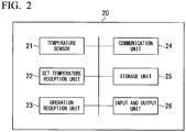
Fig. 2 is a block diagram of a remote controller in the embodiment of the present invention. -
Fig. 3A is a first diagram which shows an example of a display screen of the remote controller in the embodiment of the present invention. -
Fig. 3B is a second diagram which shows an example of the display screen of the remote controller in the embodiment of the present invention. -
Fig. 4A is a third diagram which shows an example of the display screen of the remote controller in the embodiment of the present invention. -
Fig. 4B is a fourth diagram which shows an example of the display screen of the remote controller in the embodiment of the present invention. -
Fig. 4C is a fifth diagram which shows an example of the display screen of the remote controller in the embodiment of the present invention. -
Fig. 4D is a sixth diagram which shows an example of the display screen of the remote controller in the embodiment of the present invention. -
Fig. 5 is a flowchart at the time of an air conditioning operation of a temperature management system according to the embodiment of the present invention. -
Fig. 6 is an application example of the temperature management system in the embodiment of the present invention. -
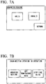
Fig. 7A is a seventh diagram which shows an example of the display screen of the remote controller in the embodiment of the present invention. -
Fig. 7B is an eighth diagram which shows an example of the display screen of the remote controller in the embodiment of the present invention. -
Fig. 8A is a ninth diagram which shows an example of the display screen of the remote controller in the embodiment of the present invention. -
Fig. 8B is a tenth diagram which shows an example of the display screen of the remote controller in the embodiment of the present invention. -
Fig. 9 is a diagram which shows a configuration example of a conventional temperature management system. - Hereinafter, a temperature management system according to an embodiment of the present invention will be described with reference to
Figs. 1 to 9 . -
Fig. 1 is a diagram which shows a configuration example of a temperature management system according to the embodiment of the present invention.Fig. 9 is a diagram which shows a configuration example of a conventional temperature management system. - As shown in
Fig. 1 , a temperature management system 1 according to the embodiment of the present invention is configured to include achilling unit 10, aremote controller 20 of thechilling unit 10, andpiping 30. Thechilling unit 10 is a device that supplies a refrigerant to a load. Thechilling unit 10 includes acontrol device 11 and arefrigerant circuit 12. Thecontrol device 11 receives information indicating a set temperature of the refrigerant from theremote controller 20, and controls an operation of therefrigerant circuit 12 such that the refrigerant is at a desired temperature on the basis of the information. As a result, thechilling unit 10 supplies the refrigerant cooled or heated to the desired temperature. The information indicating the set temperature of the refrigerant will be described with reference toFigs. 4A to 4D . - The refrigerant supplied by the
chilling unit 10 flows through the piping 30 in a direction of an arrow, and is transported to a load side (room 40). In theroom 40, refrigerants flowing throughpiping room 40, and theroom 40 is cooled or heated. The refrigerant after the heat exchange flows through the piping 30 to return to thechilling unit 10, and is cooled or heated to a desired temperature again to circulate through a similar path. In the present embodiment, the refrigerant is, for example, water. Theroom 40 includes, for example, an office or a shopping mall as in general air conditioning applications, or a room such as a vinyl house, a factory, a livestock barn, or a poultry house. - In the present specification, a chilling unit system which includes the
chilling unit 10 and theremote controller 20 will be described. - The
remote controller 20 is installed in theroom 40 which is a space on the load side. Theremote controller 20 includes a temperature sensor such as the thermistor, detects the temperature of theroom 40, and transmits information on the temperature to thecontrol device 11. Thecontrol device 11 adjusts the temperature of a refrigerant on the basis of the temperature information acquired from theremote controller 20. - Next, the temperature management system 1 of the present embodiment will be compared with a conventional temperature management system 1' shown in
Fig. 9 . In the conventional temperature management system 1' as shown inFig. 9 ,fan coil units fan coil unit 50a and the like are installed, aremote controller 56 and acontrol device 55 are provided. Thefan coil unit 50a includes aheat exchanger 51a and a fan 52a. Aflow control valve 54a for adjusting a flow rate of a refrigerant flowing into theheat exchanger 51a is provided on an upstream side of thefan coil unit 50a of thepiping 30a. The same applies to thefan coil units remote controller 56 receives an input such as a set temperature of theroom 40 from a user, and transmits setting information to thecontrol device 55. Thecontrol device 55 controls rotational speeds of fans 52a to 52c and the degrees of opening offlow control valves 54a o 54c on the basis of the setting information input by a user. - In the conventional temperature management system 1', a remote controller 20' of a chilling unit 10' is used for setting input of a refrigerant temperature. That is, the chilling unit 10' supplies a refrigerant at a set temperature input using the remote controller 20' regardless of a set temperature of the load side (room 40). Then,
fan coil units 50a to 50c are used for temperature adjustment on the load side. - In the case of the conventional temperature management system 1', since the
fan coil units 50a to 50c are required, the cost is higher than that of the temperature management system 1 of the present embodiment (Fig. 1 ). - On the other hand, in the temperature management system 1 of the present embodiment, a
temperature sensor 21 is provided in theremote controller 20 and theremote controller 20 is further installed in a space on the load side, and thereby a refrigerant temperature is adjusted in accordance with the temperature on the load side detected by thetemperature sensor 21, and the refrigerant is supplied to the load. As a result, it is possible to perform temperature management of the space on the load side according to a low cost system which does not require thefan coil unit 50a and the like. - Next, the
remote controller 20 of the embodiment will be described with reference toFig. 2 . -
Fig. 2 is a block diagram of the remote controller in the embodiment of the present invention. - As shown in
Fig. 2 , theremote controller 20 includes atemperature sensor 21, a settemperature reception unit 22, anoperation reception unit 23, acommunication unit 24, astorage unit 25, and an input andoutput unit 26. - The
temperature sensor 21 detects the temperature of a space in which theremote controller 20 is installed. Thetemperature sensor 21 is, for example, a thermistor. - The set
temperature reception unit 22 receives an input of setting correspondence information in which a correspondence between the temperature of the load side and the set temperature of the refrigerant is determined in a "air conditioning operation" to be described next. The settemperature reception unit 22 receives an input of the set temperature of the refrigerant in a "water temperature operation" to be described next. - The
operation reception unit 23 receives a selection of either "water temperature operation" or "air conditioning operation." "Water temperature operation" is an operation in which thecontrol device 11 operates therefrigerant circuit 12 such that the temperature of a refrigerant supplied by thechilling unit 10 is a predetermined temperature (a set temperature of a refrigerant received by the set temperature reception unit 22). "Air conditioning operation" is an operation in which thecontrol device 11 controls therefrigerant circuit 12 such that the temperature of the refrigerant supplied by thechilling unit 10 is set as the set temperature based on the setting correspondence information in which the correspondence is determined, which is received by the settemperature reception unit 22, and the temperature detected by thetemperature sensor 21. - The
communication unit 24 transmits information received by the settemperature reception unit 22 and theoperation reception unit 23, and temperature information detected by thetemperature sensor 21 to thecontrol device 11. - The
storage unit 25 stores information received by the settemperature reception unit 22 or theoperation reception unit 23, and the like. - The input and
output unit 26 includes an input device such as a button and a touch panel, and a display device such as a liquid crystal display. The input andoutput unit 26 receives an input such as a set temperature by a user. The input andoutput unit 26 displays images of screens for various types of settings, an image displaying a currently operating operation, and the like. - Next, an example of the operation of the present embodiment will be described. In the temperature management system of the present embodiment, there are two operations of "air conditioning operation" and "water temperature operation."
-
Fig. 3A is a first diagram which shows an example of a display screen of the remote controller in the embodiment of the present invention.Fig. 3B is a second diagram which shows an example of the display screen of the remote controller in the embodiment of the present invention. -
Fig. 3A shows an example of a setting screen for switching "air conditioning operation" and "water temperature operation." In a setting screen shown inFig. 3A , if a user selects "valid," the operation is set to "air conditioning operation." On the other hand, if the user selects "invalid," a menu screen (not shown) is displayed and "water temperature operation" can be selected from the menu screen. When the operation is set to "air conditioning operation," thecontrol device 11 controls the temperature of the refrigerant supplied to the load on the basis of setting correspondence information to be described next with reference toFigs. 4A to 4D and a temperature detected by thetemperature sensor 21. When the operation is set to "water temperature operation," thecontrol device 11 controls the temperature of a refrigerant to a predetermined set temperature regardless of the temperature of the load side. The predetermined temperature in "water temperature operation" may also be set by a user's input from the setting screen (not shown) displayed by theremote controller 20. -
Fig. 3B shows an example of an image displayed by the input andoutput unit 26 when the operation is set to "air conditioning operation." The example of the image shown inFig. 3B shows that heating (heating operation) is in operation between cooling and heating. "Set temperature AUTO" indicates that the set temperature of the refrigerant is automatically controlled in accordance with correspondence between a room temperature and the set temperature, which will be described next with reference toFigs. 4A to 4D , and in accordance with the room temperature. - Next, a method of setting the refrigerant temperature when an operation is performed during an "air conditioning operation" will be described.
-
Fig. 4A is a third diagram which shows an example of the display screen of the remote controller in the embodiment of the present invention.Fig. 4B is a fourth diagram which shows an example of the display screen of the remote controller in the embodiment of the present invention.Fig. 4C is a fifth diagram which shows an example of the display screen of the remote controller in the embodiment of the present invention.Fig. 4D is a sixth diagram which shows an example of the display screen of the remote controller in the embodiment of the present invention. - Processing of the set
temperature reception unit 22 receiving an input of setting correspondence information which determines the correspondence between the temperature of the load side and the set temperature of the refrigerant will be described with reference toFigs. 4A to 4D . -
Fig. 4A andFig. 4B are examples of a screen for setting a relationship between a room temperature and the temperature of the refrigerant at the time of a cooling operation, which are displayed by the input andoutput unit 26.Fig. 4A is a screen for setting a relationship between the room temperature and the set temperature of the refrigerant at a point A. The point A is a point indicated as "A" in a graph G1 on the upper right of the setting screen ofFig. 4A . The vertical axis of the graph G1 shows the refrigerant temperature (a cooling set temperature) at the time of the cooling operation, and a horizontal axis thereof shows the room temperature. The point A is a point which determines a relationship between an upper limit value of the refrigerant temperature and the room temperature to adjust the refrigerant temperature within a certain range in accordance with the temperature of theroom 40 at the time of the cooling operation. In the case of the example ofFig. 4A , the set temperature of the refrigerant is determined to be 15 °C with respect to the room temperature equal to or lower than 20 °C. This means that thecontrol device 11 performs control such that the temperature of the refrigerant becomes 15 °C when the temperature of theroom 40 detected by thetemperature sensor 21 is equal to or lower than 20 °C (a range H1). - Next,
Fig. 4B is a screen for setting a relationship between the room temperature and the set temperature of the refrigerant at a point B. The point B is a point indicated as "B" in the graph G1 ofFig. 4A . The point B is a point which determines a relationship between a lower limit value of the refrigerant temperature and a room temperature at the time of the cooling operation. In the case of the example ofFig. 4B , the set temperature of the refrigerant is determined to be 10 °C with respect to the room temperature equal to or higher than 25 °C. This means that thecontrol device 11 performs control such that the temperature of the refrigerant becomes 10 °C when the temperature of theroom 40 detected by thetemperature sensor 21 is equal to or higher than 25 °C (a range H3). - The graph G1 shows that the
control device 11 performs control such that the temperature of the refrigerant becomes a cooling set temperature obtained by linearly interpolating the point A and the point B when the room temperature is between the lower limit value and the upper limit value (a range H2). That is, the relationship between the room temperature and the temperature of refrigerant between these limit values is represented by a line connecting the point A and the point B. A horizontal line is drawn on a left side of the point A in the graph G1, and it is shown that a cooling set temperature determined at the point A is maintained when the room temperature is lower than the point A. Likewise, a horizontal line is drawn on the right side of the point B in the graph G1, and a cooling set temperature determined at the point B is maintained even when the temperature is higher than the point B, and thereby overcooling is prevented in the specification. -
Figs. 4C and 4D are examples of the screen for setting a relationship between the room temperature and the temperature of the refrigerant at the time of the heating operation. The setting method is the same as that at the time of the cooling operation. - A vertical axis of a graph G2 represents the refrigerant temperature (heating set temperature) at the time of the heating operation, and a horizontal axis represents the room temperature.
Fig. 4C is a screen for setting a relationship between the room temperature and the set temperature of the refrigerant at the point A. The point A is a point which determines a relationship between an upper limit value of the refrigerant temperature within a certain range and the room temperature to adjust the refrigerant temperature in accordance with the temperature of theroom 40 within this range at the time of the heating operation. In the case of the example ofFig. 4C , the set temperature of the refrigerant is determined to be 55 °C with respect to the room temperature equal to or lower than 10 °C. This means that thecontrol device 11 performs control such that the temperature of the refrigerant becomes 55 °C when the temperature of theroom 40 detected by thetemperature sensor 21 is equal to or lower than 10 °C (a range H4). A horizontal line is drawn on the left side of the point A in the graph G2, and overheating is prevented in the specification by maintaining at a heating set temperature determined at the point A when the room temperature is lower than the point A. Likewise, a horizontal line is drawn on the right side of the point B in the graph G2, and it is shown that a heating set temperature determined at the point B is maintained even when the temperature is higher than the point B. -
Fig. 4D shows a screen for setting a relationship between the room temperature and the set temperature of the refrigerant at a point B. The point B is a point which determines a relationship between a lower limit value of the refrigerant temperature and a room temperature at the time of the heating operation. In the case of the example ofFig. 4D , the set temperature of the refrigerant is determined to be 30 °C with respect to the room temperature equal to or higher than 25 °C. This means that the temperature of the refrigerant is set to 30 °C when the temperature of theroom 40 detected by thetemperature sensor 21 is equal to or higher than 25 °C (a range H6). - In the case of the room temperature indicated by the range H5, the graph G2 shows that the
control device 11 performs control such that the temperature of the refrigerant becomes a heating set temperature corresponding to the temperature detected by thetemperature sensor 21, which is obtained by linearly interpolating between the point A and the point B. - An appropriate set temperature of the refrigerant with respect to the room temperature at the time of the cooling operation and the heating operation is obtained by, for example, experiments or calculations in advance, and the user performs setting on the basis of a result of the calculation, and the like.
- The user performs an input of a set temperature at the time of the cooling and heating operation from the setting screen of
Figs. 4A to 4D . Setting information in which correspondence between the room temperature and the set temperature input by the user is determined is recorded in thestorage unit 25. Thecommunication unit 24 transmits the setting correspondence information recorded in thestorage unit 25 to thecontrol device 11. Thecontrol device 11 receives the setting correspondence information. Thecommunication unit 24 transmits temperature information detected by thetemperature sensor 21 to thecontrol device 11. When thechilling unit 10 operates in the air conditioning operation, thecontrol device 11 manages the temperature of the refrigerant on the basis of this information. - Next, an example of processing flow of the temperature management system at the time of an "air conditioning operation" operation will be described with reference to
Fig. 5 . -
Fig. 5 is a flowchart at the time of the air conditioning operation of the temperature management system according to the embodiment of the present invention. - First, a user inputs a selection of "air conditioning operation" to the
remote controller 20 as described inFigs. 3A and 3B . Theoperation reception unit 23 receives an input of the selection of "air conditioning operation" (step S11). The user inputs information which designates a heating operation (heating operation) or a cooling operation (cooling operation). Theoperation reception unit 23 receives an input of the heating operation or the cooling operation. Theoperation reception unit 23 stores the received information on an operation in thestorage unit 25. - Next, the user inputs setting correspondence information in which the relationship between the room temperature and the set temperature of the refrigerant is determined as described in
Figs. 4A to 4D . The settemperature reception unit 22 receives an input of this setting correspondence information (step S12). The settemperature reception unit 22 records the received setting correspondence information in thestorage unit 25. - Next, for example, the user inputs operation start instruction information to the
remote controller 20. Then, thecommunication unit 24 transmits the operation start instruction information together with the information received in step S11 and step S12 (step S13). Thecontrol device 11 acquires this information and records it in a storage unit (not shown). Thecontrol device 11 starts an operation of thechilling unit 10. - On the other hand, the
temperature sensor 21 detects the temperature of theroom 40 in the remote controller 20 (step S14). Thecommunication unit 24 transmits temperature information (the temperature of the room 40) detected by thetemperature sensor 21 to the control device 11 (step S15). Thecontrol device 11 acquires this temperature information. - Next, the
control device 11 calculates the set temperature of the refrigerant corresponding to the temperature information acquired from theremote controller 20 on the basis of the setting correspondence information in which the relationship between the room temperature and the set temperature of the refrigerant is determined, which is previously recorded (step S16). For example, in the case of the heating operation, it is assumed that setting information shown inFig. 4B is recorded. In this case, if the temperature of theroom 40 detected by thetemperature sensor 21 is 9 °C, thecontrol device 11 determines the set temperature of the refrigerant to be 55 °C. If the temperature of theroom 40 is 26 °C, thecontrol device 11 determines the set temperature of the refrigerant to be 30 °C. For example, if the temperature of theroom 40 is between 10 °C and 25 °C, a "heating set temperature" of a point corresponding to this temperature in a straight line connecting the point A and the point B is determined to be the set temperature of the refrigerant. - Next, the
control device 11 controls therefrigerant circuit 12 such that the temperature of the refrigerant is the set temperature of the refrigerant calculated in step S16. As a result, the temperature of theroom 40 can be managed to be a desired temperature. - The same applies to processing at the time of a "hot water operation". That is, the user inputs "hot water operation" as the operation, and the set temperature of the refrigerant (for example, x °C) to the
remote controller 20. Then, theoperation reception unit 23 receives an input of a selection of "hot water operation," and the settemperature reception unit 22 receives an input of the set temperature x °C of the refrigerant. Next, if the user inputs operation start instruction information to theremote controller 20, thecommunication unit 24 transmits information on the selected operation ("hot water operation"), the refrigerant set temperature (x °C), and the operation start instruction information to thecontrol device 11. Thecontrol device 11 acquires this information and records it in the storage unit (not shown). Thecontrol device 11 starts an operation of thechilling unit 10, and controls therefrigerant circuit 12 such that the temperature of the refrigerant becomes x °C. - The embodiment in which the
remote controller 20 is installed in theroom 40 to manage the temperature of theroom 40 has been described. The temperature management system 1 of the present embodiment can be used for temperature management in, for example, a vinyl house. According to the present embodiment, since thefan coil unit 50a and the like are not required, the cost can be reduced. Conventionally, piping is often laid in a vinyl house. This piping is laid to circulate hot water heated by a boiler for room temperature management in the vinyl house. In the temperature management system 1 of the present embodiment, since existing piping can be used, the cost for introducing the system can be reduced. As a result, if the temperature management system 1 of the present embodiment is introduced, for example, in a large-scale farm, a large cost reduction effect can be obtained. - If a fan coil is used on a farm or the like, problems such as clogging of fins occur, but since the temperature management system 1 does not require the fan coil on the load side, such problems will not occur. The temperature management system 1 of the present embodiment is also suitable for temperature management of a livestock barn, a poultry house, and a factory.
- Incidentally, snow cover can be a problem in a vinyl house in a cold region. The temperature management system 1 can also be used as a snow-melting system for snow piled up on a vinyl house in addition to room temperature management in the vinyl house.
Fig. 6 shows an example in which the temperature management system 1 is applied to the room temperature management and snow-melting of avinyl house 2. In this example, the temperature management system 1 is also used for soil temperature management. -
Fig. 6 showstemperature management systems temperature management system 1A is the snow-melting system of thevinyl house 2. Thetemperature management system 1B is the room temperature management system of thevinyl house 2. Thetemperature management system 1C is the temperature management system of soil in thevinyl house 2. InFig. 6 , thechilling units vinyl house 2. Piping 30A, 30B, 30C, and 30D circulating through the inside and outside of thevinyl house 2 are laid. - The piping 30A is a snow-melting pipe provided along the roof and an outer wall of the
vinyl house 2. A refrigerant such as water supplied by thechilling unit 10A circulates through thepiping 30A, and melts snow accumulated on the roof with heat at the time of snowfall. Theremote controller 20A is installed in an environment in which the temperature of the snowfall environment can be detected (for example, over the inside of the vinyl house 2). Thechilling unit 10A controls the refrigerant temperature in accordance with the temperature inside the vinyl house detected by the temperature sensor 21A of theremote controller 20A, and supplies the refrigerant at a temperature required for snow-melting to thepiping 30A. A setting example of setting correspondence information in which a relationship between an external temperature and a set temperature of the refrigerant in the case of using a snow-melting system is determined will be described below with reference toFig. 8 . - The
piping 30B is provided to longitudinally cross the inside of thevinyl house 2 for a plurality of times. A refrigerant such as water supplied by thechilling unit 10B circulates through the piping 30B and maintains a temperature inside thevinyl house 2 at a temperature suitable for the cultivation of agricultural crops. Theremote controller 20B is installed in thevinyl house 2. Thechilling unit 10B adjusts the temperature of the refrigerant in accordance with the temperature in the house detected by the temperature sensor 21B of theremote controller 20B, and supplies the refrigerant at the temperature required for maintaining a desired room temperature to the piping 30B. The temperature of the refrigerant circulating through the piping 30B is managed according to the setting correspondence information described with reference toFigs. 4A to 4D . - The
piping 30C is provided in the ground in thevinyl house 2. A refrigerant such as water managed at a predetermined temperature circulates around thepiping 30C, and maintains a soil temperature at a temperature suitable for the cultivation of agricultural crops. Instead of water, a solution may be caused to circulate through the piping 30C to maintain the temperature of soil and supply necessary nutrients to the soil. The temperature of the refrigerant circulating through thepiping 30C is maintained at a predetermined temperature by theheat exchanger 61. - The piping 30D causes a refrigerant (heating refrigerant) supplied by the chilling unit 10C to circulate therethrough and supplies it to the
heat exchanger 61. Here, the chilling unit 10C is operated according to "water temperature operation," and the temperature of the heating refrigerant supplied by the chilling unit 10C is kept at a predetermined temperature. The refrigerant circulating through thepiping 30C is heated by theheat exchanger 61 exchanging heat with the heating refrigerant, but if the temperature of the refrigerant circulating in the soil is lower than a predetermined temperature (for example, 5 °C), theboiler 60 may be operated and the heating refrigerant may be further heated. - Here, although a case in which the chilling unit 10C used for soil temperature management is operated in "water temperature operation" has been described as an example, the chilling unit 10C may also be operated in "air conditioning operation" in which the refrigerant temperature is controlled in accordance with the temperature of soil by installing, for example, the remote controller 20C in the ground.
- As shown in
Fig. 6 , if the temperature management system 1 of the present embodiment is used, the user can easily perform a switch such that the temperature of the refrigerant supplied by thechilling unit 10 is a temperature suitable for an application and various types of temperature management (soil, room, snow-melting) required for an operation of thevinyl house 2 merely by selecting "snow-melting operation," "air conditioning operation," or "hot water operation" from theremote controller 20. - Next, an example of a setting method of a "snow-melting operation" will be described.
-
Fig. 7A is a seventh diagram which shows an example of the display screen of the remote controller in the embodiment of the present invention.Fig. 7B is an eighth diagram which shows an example of the display screen of the remote controller in the embodiment of the present invention. -
Fig. 7A shows an example of a setting screen of "snow-melting operation." In the setting screen shown inFig. 7A , if the user selects "valid", the operation is set to "snow-melting operation". On the other hand, if the user selects "invalid," the setting screen returns to a menu screen (not shown). In the menu screen, it is possible to select "water temperature operation" or "air conditioning operation" in addition to "snow-melting operation." - When the operation is set to "snow-melting operation", the
control device 11 subsequently controls the temperature of the refrigerant on the basis of the setting correspondence information described inFigs. 8A and 8B and the temperature detected by thetemperature sensor 21. -
Fig. 7B shows an example of an image displayed by the input andoutput unit 26 when "snow-melting operation" is set as the operation. In the case of "snow-melting operation", it operates in the heating operation as shown inFig. 7B . "Set temperature AUTO" indicates that the set temperature of the refrigerant is automatically controlled in accordance with correspondence between the temperature and the set temperature of the snowfall environment next exemplified inFigs. 8A and 8B and an external temperature (snowfall environment temperature). - Next, processing of receiving, by the set
temperature reception unit 22, an input of setting correspondence information in which correspondence between the snowfall environment temperature and the set temperature of the refrigerant is determined will be described with reference toFigs. 8A and 8B . -
Fig. 8A is a ninth diagram which shows an example of the display screen of the remote controller in the embodiment of the present invention.Fig. 8B is a tenth diagram which shows an example of the display screen of the remote controller in the embodiment of the present invention. -
Figs. 8A and 8B are examples of screens for setting a relationship between the snowfall environment temperature and the refrigerant temperature at the time of the snow-melting operation. The setting method is the same as that in the case of "air conditioning operation" described inFigs. 4A to 4D . A vertical axis of a graph G3 shows the refrigerant temperature (heating set temperature) at the time of the "snow-melting operation", and the horizontal axis shows the snowfall environment temperature.Fig. 8A is a screen for setting the relationship between the snowfall environment temperature and the set temperature of the refrigerant at a point A. The point A is a point which determines a relationship between the upper limit value of the refrigerant temperature in a certain range and the snowfall environment temperature to adjust the refrigerant temperature within the range in accordance with the snowfall environment temperature at the time of the snow-melting operation. In the case of the example ofFig. 8A , the set temperature of the refrigerant is determined to be 55 °C with respect to the snowfall environment temperature equal to or lower than -5 °C. This means that thecontrol device 11 performs control such that the temperature of the refrigerant is 55 °C when the temperature of the snowfall environment detected by thetemperature sensor 21 is equal to or lower than -5 °C (a range H 7). -
Fig. 8B shows a screen for setting the relationship between the snowfall environment temperature and the set temperature of the refrigerant at a point B. The point B is a point which determines the relationship between a lower limit value of the refrigerant temperature and the snow temperature environment temperature at the time of the "snow-melting operation". In the case of the example ofFig. 8B , the set temperature of the refrigerant is determined to be 30 °C with respect to the snowfall environment temperature of 10 °C. This means that thecontrol device 11 performs control such that the temperature of the refrigerant is 30 °C when the temperature of the snowfall environment detected by thetemperature sensor 21 is 10 °C (a range H9). - When the snowfall environment temperature is in the range H8, the graph G3 shows that the
control device 11 performs control such that the temperature of the refrigerant becomes the heating set temperature corresponding to the temperature detected by thetemperature sensor 21 in a line connecting the point A and the point B. - Next, processing of the temperature management system 1 at the time of the snow-melting operation will be described. First, the user sets the operation to "snow-melting operation." The
operation reception unit 23 receives an input of the selection of "snow-melting operation" and records it in thestorage unit 25. Next, the user performs an input of the set temperature from the setting screen exemplified inFigs. 8A and 8B . The settemperature reception unit 22 receives the input of setting information and records the received setting information in thestorage unit 25. Next, if the user inputs operation start instruction information to theremote controller 20, thecommunication unit 24 transmits the operation start instruction information together with information on the selected operation ("snow-melting operation") and setting correspondence information to thecontrol device 11. Thecontrol device 11 acquires these pieces of information and records them on a storage unit (not shown). Thecontrol device 11 starts the operation of thechilling unit 10. Thetemperature sensor 21 detects a snowfall environment temperature (for example, external temperature), and thecommunication unit 24 transmits the temperature information (external temperature) to thecontrol device 11. Next, thecontrol device 11 calculates the set temperature of the refrigerant according to the temperature detected by thetemperature sensor 21 on the basis of the setting correspondence information in which the relationship between the snowfall environment temperature and the refrigerant set temperature that has been received from theremote controller 20 is determined. For example, when the setting information exemplified inFigs. 8A and 8B is recorded, if the temperature detected by thetemperature sensor 21 is -5 °C., thecontrol device 11 determines the set temperature of the refrigerant to be 55 °C. Thecontrol device 11 controls therefrigerant circuit 12 such that the temperature of the refrigerant is 55 °C. - According to the present embodiment, by laying the piping 30 on the roof, outer wall, and the like of a vinyl house where snow cover occurs, and installing the
remote controller 20 in a place where the snowfall environment temperature can be detected (for example, above the inside of the house), a refrigerant (hot water) in accordance with the temperature detected by thetemperature sensor 21 can be caused to circulate through the piping 30 to perform snow-melting of snow covering the roof and the like of the vinyl house. - In the case of "snow-melting operation", a snow cover sensor may be connected to the
remote controller 20 or thecontrol device 11 instead of the temperature sensor 21 (or in addition to the temperature sensor 21). When it is connected to theremote controller 20, control to raise and lower the refrigerant temperature according to a degree of snow cover detected by the snow cover sensor may be performed. In this case, for example, in the setting screen described with reference toFigs. 8A and 8B , it is configured to input a relationship between "the degree of snow cover" and "(heating) set temperature" instead of "snowfall environment temperature." When the snow cover sensor is connected to thecontrol device 11, control to shift a refrigerant temperature value calculated by theremote controller 20 upward or downward in accordance with a detect situation of the snow cover sensor may also be performed. - In addition, it is possible to appropriately replace the constituent elements in the embodiment described above with known constituent elements in a range not departing from the spirit of the present invention. The technical scope of the present invention is not limited to the above embodiment, and various modifications can be made in the range not departing from the spirit of the present invention. For example, when piping valves on the load side are automatically or manually switched for each season, switching of the operation may be executed automatically with a schedule function of a remote control, or may also be performed by directly commanding a required operation to the
control device 11. "Water temperature operation" in the embodiment is an example of the refrigerant temperature adjustment operation, "air conditioning operation" and "snow-melting operation" are examples of the load side temperature adjustment operation. - According to the chilling unit system, the temperature management system, the remote controller, and the control method described above, it is possible to supply a refrigerant at a temperature corresponding to a load using only a chilling unit without using a fan coil.
-
- 1, 1A, 1B, 1C, 1' Temperature management system
- 10, 10' Chilling unit
- 11 Control device
- 12 Refrigerant circuit
- 20, 20' Remote controller
- 21 Temperature sensor
- 22 Set temperature reception unit
- 23 Operation reception unit
- 24 Communication unit
- 25 Storage unit
- 30, 30a, 30b, 30c Piping
- 40 Room
- 50a, 50b, 50c Fan Coil unit
- 55 Control device
- 56 Remote controller
- G1, G2, G3 Graph
Claims (12)
- A chilling unit system comprising:a chilling unit configured to supply a refrigerant to piping laid on a load side;a remote controller which is provided in a space on the load side and has a temperature sensor for detecting a temperature of the space; anda control device configured to control the chilling unit,wherein the control device controls the chilling unit such that a temperature of the refrigerant is a temperature corresponding to a temperature detected by the temperature sensor.
- The chilling unit system according to claim 1,
wherein the remote controller further includes
an operation reception unit which is configured to receive a selection of one of a refrigerant temperature adjustment operation and a load side temperature adjustment operation,
the control device is configured to control the chilling unit such that a temperature of the refrigerant is a predetermined set temperature when the operation reception unit receives a selection of the refrigerant temperature adjustment operation, and
is configured to control the chilling unit such that the temperature of the refrigerant is a temperature corresponding to a temperature detected by the temperature sensor when the operation reception unit receives a selection of the load side temperature adjustment operation. - The chilling unit system according to claim 2,
wherein the remote controller further includes a set temperature reception unit which is configured to receive setting correspondence information in which correspondence between a temperature of the load side and a set temperature of the refrigerant is determined, and
the control device is configured to control the chilling unit such that the temperature of the refrigerant is a temperature corresponding to a temperature detected by the temperature sensor on the basis of setting correspondence information received by the set temperature reception unit when the operation reception unit receives a selection of the load side temperature adjustment operation. - The chilling unit system according to claim 2 or 3,
wherein a cooling operation which performs cooling of the space on the load side is included in the load side temperature adjustment operation. - The chilling unit system according to any one of claims 2 to 4,
wherein a heating operation which performs heating of the space on the load side is included in the load side temperature adjustment operation. - The chilling unit system according to any one of claims 2 to 5,
wherein a snow-melting operation for melting snow on the load side is included in the load side temperature adjustment operation. - A temperature management system comprising:one or a plurality pieces of piping; andthe chilling unit system described in any one of claims 1 to 6, which is configured to supply a refrigerant that circulates through the piping.
- A temperature management system comprising:piping laid in a room of a vinyl house; andthe chilling unit system described in any one of claims 1 to 5, which is configured to supply a refrigerant circulating through the piping.
- The temperature management system according to claim 8, further comprising:snow-melting piping laid on at least one of a roof and an outer wall of the vinyl house; andthe chilling unit system described in claim 6, which is configured to supply a refrigerant circulating through the snow-melting piping.
- A temperature management system comprising:snow-melting piping laid on at least one of a roof and an outer wall of a vinyl house; andthe chilling unit system described in claim 6, which is configured to supply a refrigerant circulating through the snow-melting piping.
- A remote controller of a chilling unit which is configured to supply a refrigerant to piping laid on a load side comprising:a temperature sensor which is installed in a space on the load side and is configured to detect a temperature of the space on the load side.
- A control method comprising:transmitting, by a remote controller of a chilling unit which is provided in a space on a load side and has a temperature sensor for detecting a temperature of the space, temperature information detected by the temperature sensor to a control device of the chilling unit; andperforming, by the control device, control such that a temperature of a refrigerant supplied by the chilling unit is a temperature corresponding to temperature information received from the temperature sensor.
Applications Claiming Priority (2)
| Application Number | Priority Date | Filing Date | Title |
|---|---|---|---|
| JP2016230975A JP2018087658A (en) | 2016-11-29 | 2016-11-29 | Chilling unit system, temperature control system, remote controller, and control method |
| PCT/JP2017/040063 WO2018100976A1 (en) | 2016-11-29 | 2017-11-07 | Chilling unit system, temperature management system, remote controller, and control method |
Publications (2)
| Publication Number | Publication Date |
|---|---|
| EP3486576A1 true EP3486576A1 (en) | 2019-05-22 |
| EP3486576A4 EP3486576A4 (en) | 2019-10-09 |
Family
ID=62242895
Family Applications (1)
| Application Number | Title | Priority Date | Filing Date |
|---|---|---|---|
| EP17875441.2A Withdrawn EP3486576A4 (en) | 2016-11-29 | 2017-11-07 | COOLING UNIT SYSTEM, TEMPERATURE MANAGEMENT SYSTEM, REMOTE CONTROL DEVICE, AND CONTROL METHOD |
Country Status (5)
| Country | Link |
|---|---|
| EP (1) | EP3486576A4 (en) |
| JP (1) | JP2018087658A (en) |
| KR (1) | KR20190003637A (en) |
| CN (1) | CN109312947A (en) |
| WO (1) | WO2018100976A1 (en) |
Families Citing this family (4)
| Publication number | Priority date | Publication date | Assignee | Title |
|---|---|---|---|---|
| JP7502728B2 (en) * | 2020-03-23 | 2024-06-19 | 日本キヤリア株式会社 | Heat Source System |
| CN113068546A (en) * | 2021-03-31 | 2021-07-06 | 广东积微科技有限公司 | Air conditioner control method for greenhouse low-temperature refrigeration |
| CN113940218B (en) * | 2021-09-30 | 2022-09-16 | 上海易航海芯农业科技有限公司 | Intelligent heat supply method and system for greenhouse |
| JP7693505B2 (en) * | 2021-10-15 | 2025-06-17 | 株式会社前川製作所 | Refrigeration system and operation method |
Family Cites Families (18)
| Publication number | Priority date | Publication date | Assignee | Title |
|---|---|---|---|---|
| JPS57140634U (en) * | 1981-02-27 | 1982-09-03 | ||
| JPH1019281A (en) * | 1996-06-28 | 1998-01-23 | Sanyo Electric Co Ltd | Hot water heating device |
| JP2000262160A (en) * | 1999-03-16 | 2000-09-26 | Nepon Inc | Adjustment of heat source water temperature for heating horticultural greenhouse |
| JP4622090B2 (en) * | 2000-11-21 | 2011-02-02 | 井関農機株式会社 | House snow melting equipment |
| JP3813096B2 (en) * | 2002-01-31 | 2006-08-23 | 東洋ビル管理株式会社 | Building air conditioning system |
| JP3834577B2 (en) * | 2005-03-24 | 2006-10-18 | 日立ホーム・アンド・ライフ・ソリューション株式会社 | Heat pump heating system |
| JP5036793B2 (en) * | 2009-11-27 | 2012-09-26 | 三菱電機株式会社 | Air conditioner control device |
| CN102840634B (en) * | 2011-06-24 | 2015-09-09 | 杭州三花研究院有限公司 | A kind of air-conditioning system |
| JP5786242B2 (en) * | 2011-08-02 | 2015-09-30 | 豊田興産株式会社 | Snow melting equipment for a multi-storey greenhouse |
| JP2013215182A (en) * | 2012-04-09 | 2013-10-24 | Soki:Kk | Greenhouse heating system |
| AU2012392672B2 (en) * | 2012-10-18 | 2015-06-11 | Daikin Europe N.V. | Air conditioning apparatus |
| JP5781060B2 (en) * | 2012-12-25 | 2015-09-16 | 三菱電機株式会社 | Air conditioner |
| US10323862B2 (en) * | 2012-12-28 | 2019-06-18 | Mitsubishi Electric Corporation | Air conditioning unit having dynamic target condensing and evaporating values based on load requirements |
| CN103185387B (en) * | 2013-03-28 | 2015-10-21 | 广东美的制冷设备有限公司 | Air-conditioner and leaving air temp control method thereof |
| JP6240900B2 (en) * | 2013-07-03 | 2017-12-06 | パナソニックIpマネジメント株式会社 | HEAT PUMP CONTROL DEVICE AND HEAT PUMP CONTROL DEVICE CONTROL METHOD |
| JP5984784B2 (en) * | 2013-11-19 | 2016-09-06 | 三菱電機株式会社 | Hot / cold water air conditioning system |
| KR101719772B1 (en) * | 2014-10-29 | 2017-03-28 | 대한민국 | Crops partially cooling heating system |
| JP6223315B2 (en) * | 2014-11-07 | 2017-11-01 | 三菱電機株式会社 | Cold / hot water air conditioning system |
-
2016
- 2016-11-29 JP JP2016230975A patent/JP2018087658A/en active Pending
-
2017
- 2017-11-07 CN CN201780033502.6A patent/CN109312947A/en active Pending
- 2017-11-07 KR KR1020187034286A patent/KR20190003637A/en not_active Ceased
- 2017-11-07 WO PCT/JP2017/040063 patent/WO2018100976A1/en not_active Ceased
- 2017-11-07 EP EP17875441.2A patent/EP3486576A4/en not_active Withdrawn
Also Published As
| Publication number | Publication date |
|---|---|
| EP3486576A4 (en) | 2019-10-09 |
| JP2018087658A (en) | 2018-06-07 |
| KR20190003637A (en) | 2019-01-09 |
| WO2018100976A1 (en) | 2018-06-07 |
| CN109312947A (en) | 2019-02-05 |
Similar Documents
| Publication | Publication Date | Title |
|---|---|---|
| US10082306B2 (en) | Temperature controller with model-based time to target calculation and display | |
| US9890967B2 (en) | Systems and methods for HVAC and irrigation control | |
| EP2333442B1 (en) | Air conditioner controller | |
| US20210207832A1 (en) | Thermostat and related systems | |
| EP2363658B1 (en) | Air conditioning control system | |
| US10177930B1 (en) | Smart thermostat control system | |
| KR20190003637A (en) | Chilling unit system, temperature management system, remote controller and control method | |
| US8805589B2 (en) | Air conditioning operating device and air conditioning operating method | |
| US20090032236A1 (en) | Fan coil thermostat with automatic fan reset | |
| JP6065897B2 (en) | Temperature control system | |
| US10066858B2 (en) | Method of heating a building | |
| US20230125880A1 (en) | User interfaces and controls for hvac system | |
| EP2927608B1 (en) | Heat pump system | |
| US10746415B2 (en) | Method for adjusting the setpoint temperature of a heat transfer medium | |
| JP6235937B2 (en) | Heat source equipment control device and air conditioning system | |
| US11143429B2 (en) | Control device for HVAC fan coil units | |
| US7628337B2 (en) | Secondary heating system | |
| JP6065899B2 (en) | Temperature control system | |
| KR101360682B1 (en) | Indoor air-conditioning system | |
| EP3339753B1 (en) | System and method for enforcing a manual temperature setpoint within a smart thermal management system | |
| US10274228B2 (en) | Packaged HVAC unit with secondary system capability | |
| US20100006659A1 (en) | HVAC inside and outside return air control system | |
| EP2876383B1 (en) | Heat pump system having a pressure trip sensor recalculation algorithm controller | |
| JP3145828U (en) | Greenhouse air conditioning system | |
| JP2016125676A (en) | Temperature regulation system |
Legal Events
| Date | Code | Title | Description |
|---|---|---|---|
| STAA | Information on the status of an ep patent application or granted ep patent |
Free format text: STATUS: THE INTERNATIONAL PUBLICATION HAS BEEN MADE |
|
| PUAI | Public reference made under article 153(3) epc to a published international application that has entered the european phase |
Free format text: ORIGINAL CODE: 0009012 |
|
| STAA | Information on the status of an ep patent application or granted ep patent |
Free format text: STATUS: REQUEST FOR EXAMINATION WAS MADE |
|
| 17P | Request for examination filed |
Effective date: 20190214 |
|
| AK | Designated contracting states |
Kind code of ref document: A1 Designated state(s): AL AT BE BG CH CY CZ DE DK EE ES FI FR GB GR HR HU IE IS IT LI LT LU LV MC MK MT NL NO PL PT RO RS SE SI SK SM TR |
|
| AX | Request for extension of the european patent |
Extension state: BA ME |
|
| A4 | Supplementary search report drawn up and despatched |
Effective date: 20190911 |
|
| RIC1 | Information provided on ipc code assigned before grant |
Ipc: F24F 110/10 20180101ALI20190905BHEP Ipc: F24F 11/88 20180101ALI20190905BHEP Ipc: F24F 110/00 20180101ALI20190905BHEP Ipc: F24F 11/83 20180101ALI20190905BHEP Ipc: F24F 5/00 20060101ALI20190905BHEP Ipc: F24F 11/56 20180101AFI20190905BHEP Ipc: F24F 11/65 20180101ALI20190905BHEP Ipc: F24F 11/89 20180101ALI20190905BHEP Ipc: F24F 11/62 20180101ALI20190905BHEP Ipc: F24F 11/30 20180101ALI20190905BHEP Ipc: A01G 9/24 20060101ALI20190905BHEP |
|
| DAV | Request for validation of the european patent (deleted) | ||
| DAX | Request for extension of the european patent (deleted) | ||
| STAA | Information on the status of an ep patent application or granted ep patent |
Free format text: STATUS: THE APPLICATION IS DEEMED TO BE WITHDRAWN |
|
| 18D | Application deemed to be withdrawn |
Effective date: 20200603 |