EP3486513B1 - Hub of a rolling bearing - Google Patents
Hub of a rolling bearing Download PDFInfo
- Publication number
- EP3486513B1 EP3486513B1 EP18207082.1A EP18207082A EP3486513B1 EP 3486513 B1 EP3486513 B1 EP 3486513B1 EP 18207082 A EP18207082 A EP 18207082A EP 3486513 B1 EP3486513 B1 EP 3486513B1
- Authority
- EP
- European Patent Office
- Prior art keywords
- hub
- recess
- shank
- raceway
- rolling
- Prior art date
- Legal status (The legal status is an assumption and is not a legal conclusion. Google has not performed a legal analysis and makes no representation as to the accuracy of the status listed.)
- Active
Links
Images

Classifications
-
- F—MECHANICAL ENGINEERING; LIGHTING; HEATING; WEAPONS; BLASTING
- F16—ENGINEERING ELEMENTS AND UNITS; GENERAL MEASURES FOR PRODUCING AND MAINTAINING EFFECTIVE FUNCTIONING OF MACHINES OR INSTALLATIONS; THERMAL INSULATION IN GENERAL
- F16C—SHAFTS; FLEXIBLE SHAFTS; ELEMENTS OR CRANKSHAFT MECHANISMS; ROTARY BODIES OTHER THAN GEARING ELEMENTS; BEARINGS
- F16C33/00—Parts of bearings; Special methods for making bearings or parts thereof
- F16C33/30—Parts of ball or roller bearings
- F16C33/58—Raceways; Race rings
- F16C33/581—Raceways; Race rings integral with other parts, e.g. with housings or machine elements such as shafts or gear wheels
-
- F—MECHANICAL ENGINEERING; LIGHTING; HEATING; WEAPONS; BLASTING
- F16—ENGINEERING ELEMENTS AND UNITS; GENERAL MEASURES FOR PRODUCING AND MAINTAINING EFFECTIVE FUNCTIONING OF MACHINES OR INSTALLATIONS; THERMAL INSULATION IN GENERAL
- F16C—SHAFTS; FLEXIBLE SHAFTS; ELEMENTS OR CRANKSHAFT MECHANISMS; ROTARY BODIES OTHER THAN GEARING ELEMENTS; BEARINGS
- F16C19/00—Bearings with rolling contact, for exclusively rotary movement
- F16C19/02—Bearings with rolling contact, for exclusively rotary movement with bearing balls essentially of the same size in one or more circular rows
- F16C19/14—Bearings with rolling contact, for exclusively rotary movement with bearing balls essentially of the same size in one or more circular rows for both radial and axial load
- F16C19/18—Bearings with rolling contact, for exclusively rotary movement with bearing balls essentially of the same size in one or more circular rows for both radial and axial load with two or more rows of balls
- F16C19/181—Bearings with rolling contact, for exclusively rotary movement with bearing balls essentially of the same size in one or more circular rows for both radial and axial load with two or more rows of balls with angular contact
- F16C19/183—Bearings with rolling contact, for exclusively rotary movement with bearing balls essentially of the same size in one or more circular rows for both radial and axial load with two or more rows of balls with angular contact with two rows at opposite angles
- F16C19/184—Bearings with rolling contact, for exclusively rotary movement with bearing balls essentially of the same size in one or more circular rows for both radial and axial load with two or more rows of balls with angular contact with two rows at opposite angles in O-arrangement
- F16C19/186—Bearings with rolling contact, for exclusively rotary movement with bearing balls essentially of the same size in one or more circular rows for both radial and axial load with two or more rows of balls with angular contact with two rows at opposite angles in O-arrangement with three raceways provided integrally on parts other than race rings, e.g. third generation hubs
-
- B—PERFORMING OPERATIONS; TRANSPORTING
- B60—VEHICLES IN GENERAL
- B60B—VEHICLE WHEELS; CASTORS; AXLES FOR WHEELS OR CASTORS; INCREASING WHEEL ADHESION
- B60B27/00—Hubs
- B60B27/0005—Hubs with ball bearings
-
- B—PERFORMING OPERATIONS; TRANSPORTING
- B60—VEHICLES IN GENERAL
- B60B—VEHICLE WHEELS; CASTORS; AXLES FOR WHEELS OR CASTORS; INCREASING WHEEL ADHESION
- B60B27/00—Hubs
- B60B27/0094—Hubs one or more of the bearing races are formed by the hub
-
- F—MECHANICAL ENGINEERING; LIGHTING; HEATING; WEAPONS; BLASTING
- F16—ENGINEERING ELEMENTS AND UNITS; GENERAL MEASURES FOR PRODUCING AND MAINTAINING EFFECTIVE FUNCTIONING OF MACHINES OR INSTALLATIONS; THERMAL INSULATION IN GENERAL
- F16C—SHAFTS; FLEXIBLE SHAFTS; ELEMENTS OR CRANKSHAFT MECHANISMS; ROTARY BODIES OTHER THAN GEARING ELEMENTS; BEARINGS
- F16C2326/00—Articles relating to transporting
- F16C2326/01—Parts of vehicles in general
- F16C2326/02—Wheel hubs or castors
Definitions
- the invention relates to a hub and a rolling bearing comprising a hub and an outer member arranged around said hub for mounting in relative rotation two elements.
- the invention applies more particularly to the mounting of a rolling assembly of a vehicle, in particular a motor vehicle, on a suspension element of said vehicle, said rolling assembly comprising in particular a wheel and a brake disc.
- bearings are known in which the outer member and the hub each carry at least one rolling track which are disposed radially to produce at least one rolling track in which a row of rolling body is arranged to allow relative rotation of the hub and the outer member.
- the hub comprises a shank around which the outer member is mounted in rotation, the outer periphery of said shank being provided with two internal and external rolling tracks, respectively.
- the hub comprises a flange which extends radially around the barrel, presenting ducts distributed angularly to allow the association of an element with the hub.
- the object of the invention is to improve the prior art by proposing in particular a hub of a rolling bearing whose compromise between mass and mechanical strength is optimized for the application considered, in particular with respect to the service life, rigidity and fatigue strength of said bearing.
- the invention proposes a hub of a rolling bearing having a shaft whose outer periphery is provided with at least one rolling track allowing the rotation of said hub about an axis, the barrel having at least one recess, the recess having an annular geometry of revolution around the axis of rotation, the minimum distance between the wall of said recess and the outer periphery of the barrel being greater than 10% of the diameter of the bottom of the rolling track.
- the invention provides a rolling bearing comprising such a hub, the outer periphery of the barrel of which is provided with two respectively internal and external rolling tracks, and an external member disposed around said barrel by making a respectively rolling track.
- a row of rolling bodies respectively internal and external is arranged in order to allow the relative rotation of the hub and the external member about the axis, the row of internal rolling bodies - respectively external - being in contact on the internal rolling track - respectively external - along an internal line of force - respectively external - forming with the axis of rotation of the bearing an internal contact angle - respectively external.
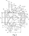
- a rolling bearing for mounting in relative rotation two elements, said bearing comprising a hub 1 and an outer member 2 arranged around said hub.
- the terms “outside” and “inside” are defined with respect to the axis X of rotation of the bearing, respectively for a location remote and close to said axis.
- the bearing is intended for mounting a rolling assembly of a vehicle, in particular a motor vehicle, on a suspension element of said vehicle, said rolling assembly comprising in particular a wheel and a brake disc.
- the hub 1 comprises a shaft 3 mounted to rotate in the outer member 2, said outer member having means for association with a vehicle suspension element.
- the invention is not limited to such an application and can be applied to an assembly in which the outer member 2 is rotating and the hub 1 is fixed.
- the outer periphery of the barrel 3 is provided with two respectively internal 4 i and external 4 e rolling tracks which each extend in a circular manner being spaced apart axially from one another.
- the terms “external” and “internal” are defined with respect to the mounting of the bearing on the vehicle, respectively on the left and on the right on the figure 2 .
- the outer member 2 is arranged around the barrel 3 by making a respectively internal 5 i and external 5 e raceway in each of which a row of respectively internal 6 i and external 6 e rolling bodies is arranged in order to allow the relative rotation of the hub 1 and the outer member 2 around the X axis.
- the shank 3 has an external rolling track 4 th and an internal bearing surface 7 intended to receive a ring 8 on which an internal rolling track 4 i is formed, the free edge 9 of said bearing surface being folded back. to form an axial preloading collar of said ring on the periphery of the barrel 3.
- the outer member 2 also has an internal rolling track 10 i and an external rolling track 10 e which are each disposed radially facing the rolling track 4 i , corresponding 4 th of the barrel 3, a row of spherical balls 6 i , 6 e being in angular contact in the raceways 5 i , 5 e thus formed.
- the invention is not limited to a particular embodiment of the function of rotation of the rolling bearing, in particular with regard to the geometry of the rolling bodies 6 i , 6 e and of the various rolling tracks 4 i , 4 e ; 10 i , 10 e on the barrel 3 and / or the external member 2.
- the barrel 3 is equipped with a flange 11 which is formed around the outer side of said barrel, said flange extending radially by presenting association conduits 12 distributed angularly .
- the flange 11 has an annular extension 13 which extends axially from an outer side of the barrel 3, the rolling assembly having a bore which is arranged around said annular extension ensuring perfect concentricity of the mounting of said rolling assembly on said flange before it is fixed in the ducts 12.
- the flange has a disc 20 which extends radially around the barrel 3, said disc being equipped with ducts 12 distributed angularly to allow the association of an element with the hub, each of said ducts being connected to the barrel 3 by a rib 21 protruding from the face of disc 20 extending radially, said rib being inscribed in an angular sector S of said disc.
- the hub 1 is produced in a single piece and can be optimized, in particular in terms of the material constituting it, relative to the mechanical forces to which it must withstand.
- the hub 1 can be made, in particular by forging, in a metallic material, in particular in rolling steel of the type C56, to allow the barrel 3 to withstand the rolling contact pressures and the flange 11 to withstand the mechanical stresses coming from the rolling assembly.
- the hub 1 can be obtained by additive manufacturing, in particular by laser sintering of a steel powder with a high carbon content, for example of the 100Cr6 type.
- the row of internal rolling bodies 6i - respectively external 6 e - is in contact with the internal rolling track 5i-respectively external 5 e - along an internal force line L i - respectively external L e - forming with the axis of rotation X of the bearing an internal contact angle ⁇ ci - respectively external ⁇ ce .
- the line of force L i , L e is considered at the level of the rolling body 6 i , 6 e most heavily loaded on each of the internal and external sides respectively.
- the barrel 3 has at least one annular recess 22, 23 of revolution about the axis of rotation X. To optimize the weight of the hub 1 without compromising its mechanical strength, the minimum distance between the wall of the recess 22, 23 and the outer periphery of the barrel 3 is greater than 10% of the diameter D of the bottom of the rolling track 4 i , 4 e .
- the annular recess 22, 23 has a section which extends angularly over 360 ° to form an uninterrupted recess.
- the geometry of the section of the recess 22, 23 can be triangular, circular to form a torus, or according to another geometry, possibly angularly changing.
- the hub 1 has an internal recess 22 which is formed in the internal side of the barrel 3.
- the internal recess 22 is surrounded by the ring 8, in particular having a maximum diameter which is smaller. the diameter D of the track base bearing 4i, 4 th.
- the minimum radial distance between the outer wall of the internal recess 22 and the internal bearing surface 7 of the barrel is greater than 10% of the diameter D of the bottom of the rolling track 4 i , 4 e .
- a sufficient thickness E of material can be placed between the ring 8 and the internal recess 22, in particular relative to the rigidity vis-à-vis the pressure exerted by the rolling bodies 6 e on the rolling track 4i of said Ring.
- the hub 1 shown also has an external recess 23 which is surrounded by the flange 11, in particular having a wall which has a minimum diameter D min which is greater than the diameter D of the bottom of the rolling track 4 i , 4 e .
- the wall of the outer recess has an outer plane P e which is disposed on the inner side of an outer lateral plane P of the flange 11.
- the external recess 23 has a section which is locally increased over at least part of the angular sectors S of the ribs 21 in order to form a chamber 24 under each of said ribs.
- the volume of the external recess 23 can be locally increased to make the hub 1 lighter without compromising its mechanical performance.
- the chamber 24 has a section at least doubled with respect to the section of the external recess 23.
- the section of the chamber 24 has a triangular geometry which corresponds to a doubling of the triangular section of the external recess 23.
- the shank 3 also has a central recess 14 of revolution about the axis of rotation X, said recess comprising an internal conical part 14 i and an external conical part 14 e which are interconnected by their base at the level of a central part 14 c .
- the minimum distance between the walls of the internal 22 and central 14 recesses is greater than 20% of the diameter D of the bottom of the raceway 4 i , 4 e .
- said recess can be connected to the outside of the barrel by a duct 25.
- the barrel 3 may have an outer edge in which a conical cavity of revolution 15 is formed.
- the cavity 15 forms a solid angle which is essentially equal to that formed by revolution of the external force line L e .
- the conical cavity 15 opens into the cylindrical cavity formed by the annular extension 13 of the flange 11, the wall of the conical cavity 15 being substantially tangent to the external force line L e .
- a cavity of revolution 16 can be formed in the internal edge of the barrel 3, in particular inside the flange 9 for the association of the ring 8, said cavity possibly having a substantially spherical bottom in which said edge is formed.
- the minimum distance between the wall of the internal recess 22 and the periphery of the cavity 16 is greater than 10% of the diameter D of the bottom of the rolling track 4 i , 4 e .
Description
L'invention concerne un moyeu ainsi qu'un palier à roulement comprenant un moyeu et un organe extérieur disposé autour dudit moyeu pour le montage en rotation relative de deux éléments.The invention relates to a hub and a rolling bearing comprising a hub and an outer member arranged around said hub for mounting in relative rotation two elements.
L'invention s'applique plus particulièrement au montage d'un ensemble roulant de véhicule, notamment automobile, sur un élément de suspension dudit véhicule, ledit ensemble roulant comprenant notamment une roue et un disque de frein.The invention applies more particularly to the mounting of a rolling assembly of a vehicle, in particular a motor vehicle, on a suspension element of said vehicle, said rolling assembly comprising in particular a wheel and a brake disc.
Pour le montage d'un tel ensemble roulant, on connaît des paliers dans lesquels l'organe extérieur et le moyeu portent chacun au moins une piste de roulement qui sont disposées en regard radial pour réaliser au moins un chemin de roulement dans lequel une rangée de corps roulants est disposée afin de permettre la rotation relative du moyeu et de l'organe extérieur.For mounting such a rolling assembly, bearings are known in which the outer member and the hub each carry at least one rolling track which are disposed radially to produce at least one rolling track in which a row of rolling body is arranged to allow relative rotation of the hub and the outer member.
Selon une réalisation, notamment décrite dans le document
Par ailleurs, le moyeu comprend un flasque qui s'étend radialement autour du fût en présentant des conduits répartis angulairement pour permettre l'association d'un élément au moyeu. Ainsi, en associant l'organe extérieur à un élément de suspension du véhicule, on peut monter en rotation l'ensemble roulant en le fixant au flasque.Furthermore, the hub comprises a flange which extends radially around the barrel, presenting ducts distributed angularly to allow the association of an element with the hub. Thus, by associating the external member with a suspension element of the vehicle, the rolling assembly can be mounted in rotation by fixing it to the flange.
De par l'intégration des différentes fonctions et des sollicitations mécaniques qui en résultent, les paliers à roulement sont relativement massifs, ce qui pose des problèmes de poids, d'encombrement et de coûts.Due to the integration of the various functions and the resulting mechanical stresses, rolling bearings are relatively massive, which poses problems of weight, size and costs.
L'invention a pour but de perfectionner l'art antérieur en proposant notamment un moyeu d'un palier à roulement dont le compromis entre la masse et la résistance mécanique est optimisé pour l'application considérée, notamment relativement à la durée de vie, à la rigidité et à la tenue en fatigue dudit palier.The object of the invention is to improve the prior art by proposing in particular a hub of a rolling bearing whose compromise between mass and mechanical strength is optimized for the application considered, in particular with respect to the service life, rigidity and fatigue strength of said bearing.
A cet effet, et selon un premier aspect, l'invention propose un moyeu d'un palier à roulement présentant un fût dont la périphérie extérieure est pourvue d'au moins une piste de roulement permettant la rotation dudit moyeu autour d'un axe, le fût présentant au moins un évidement, l'évidement présentant une géométrie annulaire de révolution autour de l'axe de rotation, la distance minimale entre la paroi dudit évidement et la périphérie extérieure du fût étant supérieure à 10% du diamètre du fond de la piste de roulement.To this end, and according to a first aspect, the invention proposes a hub of a rolling bearing having a shaft whose outer periphery is provided with at least one rolling track allowing the rotation of said hub about an axis, the barrel having at least one recess, the recess having an annular geometry of revolution around the axis of rotation, the minimum distance between the wall of said recess and the outer periphery of the barrel being greater than 10% of the diameter of the bottom of the rolling track.
Selon un deuxième aspect, l'invention propose un palier à roulement comprenant un tel moyeu dont la périphérie extérieure du fût est pourvue de deux pistes de roulement respectivement interne et externe, et un organe extérieur disposé autour dudit fût en réalisant un chemin de roulement respectivement interne et externe dans chacun desquels une rangée de corps roulants respectivement interne et externe est disposée afin de permettre la rotation relative du moyeu et de l'organe extérieur autour de l'axe, la rangée de corps roulants interne - respectivement externe - étant en contact sur la piste de roulement interne - respectivement externe - selon une ligne d'effort interne - respectivement externe - formant avec l'axe de rotation du palier un angle de contact interne - respectivement externe.According to a second aspect, the invention provides a rolling bearing comprising such a hub, the outer periphery of the barrel of which is provided with two respectively internal and external rolling tracks, and an external member disposed around said barrel by making a respectively rolling track. internal and external in each of which a row of rolling bodies respectively internal and external is arranged in order to allow the relative rotation of the hub and the external member about the axis, the row of internal rolling bodies - respectively external - being in contact on the internal rolling track - respectively external - along an internal line of force - respectively external - forming with the axis of rotation of the bearing an internal contact angle - respectively external.
D'autres objets et avantages de l'invention apparaîtront dans la description qui suit, faite en référence aux figures annexées, dans lesquelles :
- les
figures 1a et 1b représentent un moyeu selon un mode de réalisation de l'invention, respectivement en perspective (figure 1a ) et en coupe transversale (figure 1b ) ; - la
figure 2 représente en coupe longitudinale un palier à roulement comprenant un moyeu selon lesfigures 1a et 1b .
- the
figures 1a and 1b represent a hub according to an embodiment of the invention, respectively in perspective (figure 1a ) and in cross section (figure 1b ); - the
figure 2 shows in longitudinal section a rolling bearing comprising a hub according tofigures 1a and 1b .
En relation avec ces figures, on décrit ci-dessous un palier à roulement pour le montage en rotation relative de deux éléments, ledit palier comprenant un moyeu 1 et un organe extérieur 2 disposé autour dudit moyeu. Dans la description, les termes « extérieur » et « intérieur » sont définis par rapport à l'axe X de rotation du palier, respectivement pour une localisation éloignée et proche dudit axe.In relation to these figures, a rolling bearing is described below for mounting in relative rotation two elements, said bearing comprising a
Dans le mode de réalisation représenté, le palier est destiné au montage d'un ensemble roulant de véhicule, notamment automobile, sur un élément de suspension dudit véhicule, ledit ensemble roulant comprenant notamment une roue et un disque de frein.In the embodiment shown, the bearing is intended for mounting a rolling assembly of a vehicle, in particular a motor vehicle, on a suspension element of said vehicle, said rolling assembly comprising in particular a wheel and a brake disc.
Pour ce faire, le moyeu 1 comprend un fût 3 monté tournant dans l'organe extérieur 2, ledit organe extérieur présentant des moyens d'association à un élément de suspension du véhicule. Toutefois, l'invention n'est pas limitée à une telle application et peut s'appliquer à un montage dans lequel l'organe extérieur 2 est tournant et le moyeu 1 est fixe.To do this, the
La périphérie extérieure du fût 3 est pourvue de deux pistes de roulement respectivement interne 4i et externe 4e qui s'étendent chacune de façon circulaire en étant espacées axialement l'une de l'autre. Dans la description, les termes « externe » et « interne » sont définis par rapport au montage du palier sur le véhicule, respectivement à gauche et à droite sur la
L'organe extérieur 2 est disposé autour du fût 3 en réalisant un chemin de roulement respectivement interne 5i et externe 5e dans chacun desquels une rangée de corps roulants respectivement interne 6i et externe 6e est disposée afin de permettre la rotation relative du moyeu 1 et de l'organe extérieur 2 autour de l'axe X.The
Dans le mode de réalisation représenté, le fût 3 présente une piste de roulement externe 4e et une portée interne 7 destinée à recevoir une bague 8 sur laquelle une piste de roulement interne 4i est formée, le bord libre 9 de ladite portée étant replié pour former une collerette de précharge axiale de ladite bague sur la périphérie du fût 3.In the embodiment shown, the
Par ailleurs, l'organe extérieur 2 présente également une piste de roulement interne 10i et une piste de roulement externe 10e qui sont disposées chacune en regard radial de la piste de roulement 4i, 4e correspondante du fût 3, une rangée de billes sphériques 6i, 6e étant en contact oblique dans les chemins de roulement 5i, 5e ainsi formés.Furthermore, the
Toutefois, l'invention n'est pas limitée à une réalisation particulière de la fonction de rotation du palier à roulement, notamment relativement à la géométrie des corps roulants 6i, 6e et des différentes pistes de roulement 4i, 4e ; 10i, 10e sur le fût 3 et/ou l'organe extérieur 2.However, the invention is not limited to a particular embodiment of the function of rotation of the rolling bearing, in particular with regard to the geometry of the rolling bodies 6 i , 6 e and of the various rolling tracks 4 i , 4 e ; 10 i , 10 e on the
Pour permettre l'association d'un ensemble roulant au moyeu 1, le fût 3 est équipé d'un flasque 11 qui est formé autour du côté externe dudit fût, ledit flasque s'étendant radialement en présentant des conduits 12 d'association répartis angulairement.To allow the association of a rolling assembly with the
En particulier, le flasque 11 présente une extension annulaire 13 qui s'étend axialement depuis un côté externe du fût 3, l'ensemble roulant présentant un alésage qui est disposé autour de ladite extension annulaire en assurant une concentricité parfaite du montage dudit ensemble roulant sur ledit flasque avant sa fixation dans les conduits 12.In particular, the flange 11 has an
Par ailleurs, le flasque présente un disque 20 qui s'étend radialement autour du fût 3, ledit disque étant équipé de conduits 12 répartis angulairement pour permettre l'association d'un élément au moyeu, chacun desdits conduits étant reliés au fût 3 par une nervure 21 formée en saillance sur la face du disque 20 en s'étendant radialement, ladite nervure étant inscrite dans un secteur angulaire S dudit disque.Furthermore, the flange has a disc 20 which extends radially around the
Le moyeu 1 est réalisé en une seule pièce et peut être optimisé, notamment au niveau du matériau le constituant, relativement aux efforts mécaniques auxquels il doit résister. Selon une réalisation, le moyeu 1 peut être réalisé, notamment par forgeage, dans un matériau métallique, notamment en acier à roulement de type C56, pour permettre au fût 3 de supporter les pressions de contact de roulement et au flasque 11 de supporter les contraintes mécaniques venant de l'ensemble roulant. Selon une autre réalisation, le moyeu 1 peut être obtenu par fabrication additive, notamment par frittage laser d'une poudre d'acier à haute teneur en carbone, par exemple de type 100Cr6.The
Comme représenté sur la
Le fût 3 présente au moins un évidement 22, 23 annulaire de révolution autour de l'axe de rotation X. Pour optimiser le poids du moyeu 1 sans pour autant compromettre sa résistance mécanique, la distance minimale entre la paroi de l'évidement 22, 23 et la périphérie extérieure du fût 3 est supérieure à 10% du diamètre D du fond de la piste de roulement 4i, 4e.The
Dans le mode de réalisation représenté, l'évidement annulaire 22, 23 présente une section qui s'étend angulairement sur 360° pour former un évidement ininterrompu. En particulier, la géométrie de la section de l'évidement 22, 23 peut être triangulaire, circulaire pour former un tore, ou suivant une autre géométrie, éventuellement évolutive angulairement.In the embodiment shown, the
La taille de l'évidement annulaire 22, 23 et donc le gain de poids peuvent être augmentés tout en conservant suffisamment de matière pour la résistance mécanique en prévoyant qu'il présente :
- une longueur axiale, c'est-à-dire mesurée entre ses bords interne et externe le long de l'axe X, comprise entre 5% et 15% de la longueur axiale L du
fût 3 prise entre ses bords interne et externe ; et/ou - une hauteur radiale comprise entre 10% et 30% du diamètre D du fond de la piste de roulement 4i, 4e.
- an axial length, that is to say measured between its inner and outer edges along the X axis, between 5% and 15% of the axial length L of the
barrel 3 taken between its inner and outer edges; and or - a radial height of between 10% and 30% of the diameter D of the bottom of the rolling track 4 i , 4 e .
Dans le mode de réalisation représenté, le moyeu 1 présente un évidement interne 22 qui est formé dans le côté interne du fût 3. En particulier, l'évidement interne 22 est entouré par la bague 8, notamment en présentant un diamètre maximal qui est inférieur au diamètre D du fond de la piste de roulement 4i, 4e.In the embodiment shown, the
Selon une réalisation, la distance radiale minimale entre la paroi extérieure de l'évidement interne 22 et la portée interne 7 du fût est supérieure à 10% du diamètre D du fond de la piste de roulement 4i, 4e. Ainsi, une épaisseur E de matière suffisante peut être disposée entre la bague 8 et l'évidement interne 22, notamment relativement à la rigidité vis-à-vis de la pression exercée par les corps roulants 6e sur la piste de roulement 4i de ladite bague.According to one embodiment, the minimum radial distance between the outer wall of the
Le moyeu 1 représenté présente également un évidement externe 23 qui est entouré par le flasque 11, notamment en ayant une paroi qui présente un diamètre minimum Dmin qui est supérieur au diamètre D du fond de la piste de roulement 4i, 4e. En outre, pour conserver une épaisseur de matière suffisante, la paroi de l'évidement externe présente un plan externe Pe qui est disposé du côté interne d'un plan latéral externe P du flasque 11.The
Selon une réalisation avantageuse, l'évidement externe 23 présente une section qui est localement augmentée sur au moins une partie des secteurs angulaires S des nervures 21 afin de former une chambre 24 sous chacune desdites nervures. Ainsi, du fait de la rigidité apportée par les nervures 21, le volume de l'évidement externe 23 peut être localement augmenté pour conférer un allègement du moyeu 1 sans compromettre ses performances mécaniques.According to an advantageous embodiment, the
Le compromis entre poids et résistance mécanique peut être optimisé en prévoyant que :
- la distance axiale d1 entre le bord interne d'une
chambre 24 et la piste de roulement externe 4e soit comprise entre 90% et 110% de la dimension axiale d de lanervure 21 correspondante, notamment en étant sensiblement égale à elle ; et/ou - la dimension angulaire d2 d'une
chambre 24 soit comprise entre 90% et 110% de la dimension du secteur angulaire S de lanervure 21 correspondante, notamment en étant sensiblement égale à elle.
- the axial distance d 1 between the inner edge of a
chamber 24 and the outer raceway 4 e is between 90% and 110% of the dimension axial d of thecorresponding rib 21, in particular by being substantially equal to it; and or - the angular dimension d 2 of a
chamber 24 is between 90% and 110% of the dimension of the angular sector S of thecorresponding rib 21, in particular by being substantially equal to it.
Selon une réalisation, la chambre 24 présente une section au moins doublée par rapport à la section de l'évidement externe 23. En relation avec la
Dans le mode de réalisation représenté, le fût 3 présente en outre un évidement 14 central de révolution autour de l'axe de rotation X, ledit évidement comprenant une partie conique interne 14i et une partie conique externe 14e qui sont reliées entre elles par leur base au niveau d'une partie centrale 14c.In the embodiment shown, the
Pour optimiser le poids du palier sans pour autant compromettre sa résistance mécanique, la distance minimale entre les parois des évidements interne 22 et central 14 est supérieure à 20% du diamètre D du fond de la piste de roulement 4i, 4e. Par ailleurs, l'évidement externe 23 présente une paroi extérieure qui peut former un angle αi avec l'axe de rotation X qui est tel que : αi = 90 - αce ± 3°.To optimize the weight of the bearing without compromising its mechanical strength, the minimum distance between the walls of the internal 22 and central 14 recesses is greater than 20% of the diameter D of the bottom of the raceway 4 i , 4 e . Furthermore, the
Pour des raisons de fabrication, notamment en fabrication additive mais également pour éliminer un éventuel insert ayant servi à former un évidement 14, 22, 23, ledit évidement peut être relié à l'extérieur du fût par un conduit 25.For manufacturing reasons, especially in additive manufacturing but also to eliminate a possible insert having served to form a
Dans l'optique d'un gain de poids, le fût 3 peut présenter un bord externe dans lequel une cavité conique de révolution 15 est formée. En particulier, et comme représenté sur la
Plus précisément, la cavité conique 15 débouche dans la cavité cylindrique formée par l'extension annulaire 13 du flasque 11, la paroi de la cavité conique 15 étant sensiblement tangente à la ligne d'effort externe Le.More precisely, the conical cavity 15 opens into the cylindrical cavity formed by the
Du côté interne du moyeu 3, toujours pour optimiser le compromis masse / résistance mécanique, une cavité de révolution 16 peut être formée dans le bord interne du fût 3, notamment à l'intérieur de la collerette 9 d'association de la bague 8, ladite cavité pouvant présenter un fond sensiblement sphérique dans lequel ledit bord est formé. En particulier, la distance minimale entre la paroi de l'évidement interne 22 et la périphérie de la cavité 16 est supérieure à 10% du diamètre D du fond de la piste de roulement 4i, 4e.On the internal side of the
Claims (18)
- Hub (1) of a rolling bearing having a shank (3), the outer periphery of which is provided with at least one raceway (4i, 4e) allowing the rotation of said hub (1) about an axis (X), the shank (3) having at least one recess (22, 23), said bearing being characterised in that the recess (22, 23) has an annular geometry of revolution about the axis of rotation (X), the minimum distance between the wall of said recess and the outer periphery of the shank (3) being greater than 10% of the diameter D of the bottom of the raceway (4i, 4e).
- Hub (1) according to claim 1, characterised in that it has an inner recess (22) that is formed in the inner side of the shank (3).
- Hub (1) according to claim 2, characterised in that the wall of the inner recess (22) has a maximum diameter that is less than the diameter D of the bottom of the raceway (4i, 4e) .
- Hub (1) according to any one of claims 1 to 3, characterised in that it comprises a flange (11) that is formed around the outer side of the shank (3), said hub having an outer recess (23) that is surrounded by the flange (3).
- Hub (1) according to claim 4, characterised in that the wall of the outer recess (23) has a minimum diameter (Dmin) that is greater than the diameter D of the bottom of the raceway (4i, 4e) .
- Hub (1) according to one of claims 4 or 5, characterised in that the wall of the outer recess (23) has an outer plane (Pe) that is disposed on the inner side of an outer lateral plane (P) of the flange (11).
- Hub (1) according to any one of claims 4 to 6, characterised in that the flange (11) has a disc (20) that extends radially around the shank (3), said disc being equipped with ducts (12) angularly distributed to allow the association of an element with the hub (1), each of said ducts being connected to the shank (3) by a rib (21) formed on an angular sector (S) of said disc, the outer recess (23) having a cross-section that is locally increased on at least a part of the angular sectors (S) of said ribs in order to form a chamber (24) under each of said ribs.
- Hub (1) according to claim 7, characterised in that the axial distance (d1) between the inner edge of a chamber (24) and the raceway (4e) is between 90% and 110% of the axial dimension (d) of the corresponding rib (21).
- Hub (1) according to one of claims 7 or 8, characterised in that the angular dimension (d2) of a chamber (24) is between 90% and 110% of the dimension of the angular sector (S) of the corresponding rib (21).
- Hub (1) according to any one of claims 7 to 9, characterised in that a chamber (24) has a cross-section at least doubled with respect to the cross-section of the outer recess (23).
- Hub (1) according to claim 10, characterised in that the cross-section of the outer recess (23) has a triangular geometry, the cross-section of the chamber (24) having a triangular geometry that corresponds to a splitting in two of that of the cross-section of said recess.
- Hub (1) according to any one of claims 1 to 11, characterised in that the annular recess (22, 23) has an axial length that is between 5% and 15% of the axial length (L) of the shank (3) taken between its inner and outer edges.
- Hub (1) according to any one of claims 1 to 12, characterised in that the annular recess (22, 23) has a radial height that is between 10% and 30% of the diameter (D) of the bottom of the raceway (4i, 4e).
- Hub (1) according to any one of claims 1 to 13, characterised in that the shank (3) further has a central recess (14) of revolution about the axis of rotation (X), said recess comprising an inner conical part (14i) and an outer conical part (14e) that are connected to each other by their base at a central part (14c).
- Hub (1) according to claim 14 when it is dependent on claim 2, characterised in that the minimum distance between the walls of the inner (22) and central (14) recesses is greater than 20% of the diameter (D) of the bottom of the raceway (4i, 4e).
- Hub (1) according to any one of claims 1 to 15, characterised in that a recess (14, 22, 23) is connected to the outside of the shank by at least one duct (25).
- Rolling bearing comprising a hub (1) according to any one of claims 1 to 16, in which the outer periphery of the shank is provided with two raceways, respectively inner (4i) and outer (4e), and an outer member (2) disposed around said shank while creating a respectively inner (5i) and outer (5e) rolling track in each of which a row of respectively inner (6i) and outer (6e) rolling bodies is disposed in order to allow the relative rotation of the hub (1) and of the outer member (2) about the axis (X), the row of inner (6i) - and respectively outer (6e) - rolling bodies being in contact on the inner (4i) - and respectively outer (4e) - raceway according to an inner (Li) - and respectively outer (Le) - stress line forming with the axis of rotation (X) of the bearing an inner αci - and respectively outer αce - angle of contact.
- Rolling bearing according to claim 17 when it is dependent on claim 5, characterised in that the outer recess (23) has an outer wall forming an angle αi with the axis of rotation (X) which is such that:

Applications Claiming Priority (1)
| Application Number | Priority Date | Filing Date | Title |
|---|---|---|---|
| FR1760947A FR3073911B1 (en) | 2017-11-20 | 2017-11-20 | HUB FOR A ROLLING BEARING |
Publications (2)
| Publication Number | Publication Date |
|---|---|
| EP3486513A1 EP3486513A1 (en) | 2019-05-22 |
| EP3486513B1 true EP3486513B1 (en) | 2020-12-30 |
Family
ID=60765946
Family Applications (1)
| Application Number | Title | Priority Date | Filing Date |
|---|---|---|---|
| EP18207082.1A Active EP3486513B1 (en) | 2017-11-20 | 2018-11-19 | Hub of a rolling bearing |
Country Status (2)
| Country | Link |
|---|---|
| EP (1) | EP3486513B1 (en) |
| FR (1) | FR3073911B1 (en) |
Family Cites Families (5)
| Publication number | Priority date | Publication date | Assignee | Title |
|---|---|---|---|---|
| US7506940B2 (en) * | 2005-09-02 | 2009-03-24 | Hendrickson Usa, L.L.C. | Axle spindle and wheel end assembly |
| DE102008034593B4 (en) * | 2008-07-25 | 2016-12-01 | Bpw Bergische Achsen Kg | Hub for the pivotal mounting of a vehicle wheel |
| ITTO20110275A1 (en) * | 2011-03-29 | 2012-09-30 | Skf Ab | CONFIGURATION FOR COUPLING OF SHAPE IN A BEARING RING FOR THE WHEEL OF A MOTOR VEHICLE |
| ITTO20130841A1 (en) * | 2013-10-17 | 2015-04-18 | Skf Ab | HUB FOR A WHEEL OF A MOTOR VEHICLE |
| CN203651333U (en) * | 2013-12-27 | 2014-06-18 | 恩梯恩(中国)投资有限公司 | Hub bearing for wheel and related parts |
-
2017
- 2017-11-20 FR FR1760947A patent/FR3073911B1/en active Active
-
2018
- 2018-11-19 EP EP18207082.1A patent/EP3486513B1/en active Active
Non-Patent Citations (1)
| Title |
|---|
| None * |
Also Published As
| Publication number | Publication date |
|---|---|
| FR3073911A1 (en) | 2019-05-24 |
| EP3486513A1 (en) | 2019-05-22 |
| FR3073911B1 (en) | 2019-12-13 |
Similar Documents
| Publication | Publication Date | Title |
|---|---|---|
| EP1846665B1 (en) | Conical roller bearing comprising a filter cage | |
| FR2640010A1 (en) | ARRANGEMENT FOR FIXING A HIGH-HARDNESS BEARING RING INTO THE LOWEST HARDNESS OF A HOUSING OF A HOUSING OR ON THE LOWEST HARDNESS SURFACE OF A SHAFT OR THE LIKE | |
| FR2961280A1 (en) | CLUTCH FASTENING DEVICE COMPRISING A WEAR RING. | |
| EP2488768B1 (en) | Ball bearing and corresponding bump stop | |
| FR2915543A1 (en) | BEARING BEARING DEVICE FOR STEERING COLUMN | |
| EP3486513B1 (en) | Hub of a rolling bearing | |
| WO2007010106A2 (en) | Method for mounting a bearing provided with a flange and two row of rolling elements | |
| FR3072742B1 (en) | BEARING BEARING | |
| FR2878006A3 (en) | Retention cage for ball bearing, has clamps each formed of material kink comprising inner, outer, front lateral and rear lateral zones, and material bridges disposed without connected with each other | |
| EP2963307B1 (en) | Cage for retaining rolling bodies in a roller bearing | |
| FR3049990A1 (en) | HYDRODYNAMIC MACHINE | |
| FR3064705B1 (en) | BEARING BEARING | |
| EP4162157A1 (en) | Hydraulic machine comprising bearings for supporting the rotating component | |
| FR2864591A1 (en) | Homo-kinetic transmission joint for motor vehicle, has joint ball that is moved, due to force, radially outside till frontal surface of ring, where joint ball is maintained in support on surfaces by force | |
| EP1584829B1 (en) | Roller bearing assembly having integrated means for the reduction of contact corrosion | |
| EP2878838B1 (en) | Roller bearing comprising a cage for retaining tapered rolling bodies | |
| EP2555928B1 (en) | Assembling method of a rolling bearing and mounting method of a vehicle wheel using such a bearing | |
| EP3106319B1 (en) | Roller-bearing hub including an insert | |
| FR3058486A1 (en) | BEARING BEARING HUB | |
| EP1299252B1 (en) | Roller bearing, in particular for motor vehicle non-driving wheel | |
| FR3037529A1 (en) | ROLLING BEARING HUB INTEGRATING A SEALING GAUGE | |
| FR3033184A1 (en) | BEARING BEARING COMPRISING A WEAR RING, AND METHOD OF MANUFACTURING THE SAME | |
| FR3021719A1 (en) | BEARING BEARING HUB | |
| EP2267323A2 (en) | Roller bearing | |
| EP3842649A1 (en) | Cage for retaining tapered rollers in a roller bearing |
Legal Events
| Date | Code | Title | Description |
|---|---|---|---|
| PUAI | Public reference made under article 153(3) epc to a published international application that has entered the european phase |
Free format text: ORIGINAL CODE: 0009012 |
|
| STAA | Information on the status of an ep patent application or granted ep patent |
Free format text: STATUS: THE APPLICATION HAS BEEN PUBLISHED |
|
| AK | Designated contracting states |
Kind code of ref document: A1 Designated state(s): AL AT BE BG CH CY CZ DE DK EE ES FI FR GB GR HR HU IE IS IT LI LT LU LV MC MK MT NL NO PL PT RO RS SE SI SK SM TR |
|
| AX | Request for extension of the european patent |
Extension state: BA ME |
|
| STAA | Information on the status of an ep patent application or granted ep patent |
Free format text: STATUS: REQUEST FOR EXAMINATION WAS MADE |
|
| 17P | Request for examination filed |
Effective date: 20191115 |
|
| RBV | Designated contracting states (corrected) |
Designated state(s): AL AT BE BG CH CY CZ DE DK EE ES FI FR GB GR HR HU IE IS IT LI LT LU LV MC MK MT NL NO PL PT RO RS SE SI SK SM TR |
|
| STAA | Information on the status of an ep patent application or granted ep patent |
Free format text: STATUS: EXAMINATION IS IN PROGRESS |
|
| 17Q | First examination report despatched |
Effective date: 20200424 |
|
| RIC1 | Information provided on ipc code assigned before grant |
Ipc: F16C 33/58 20060101AFI20200417BHEP Ipc: F16C 19/18 20060101ALI20200417BHEP Ipc: B60B 27/00 20060101ALI20200417BHEP |
|
| GRAP | Despatch of communication of intention to grant a patent |
Free format text: ORIGINAL CODE: EPIDOSNIGR1 |
|
| STAA | Information on the status of an ep patent application or granted ep patent |
Free format text: STATUS: GRANT OF PATENT IS INTENDED |
|
| INTG | Intention to grant announced |
Effective date: 20200612 |
|
| GRAS | Grant fee paid |
Free format text: ORIGINAL CODE: EPIDOSNIGR3 |
|
| GRAA | (expected) grant |
Free format text: ORIGINAL CODE: 0009210 |
|
| STAA | Information on the status of an ep patent application or granted ep patent |
Free format text: STATUS: THE PATENT HAS BEEN GRANTED |
|
| AK | Designated contracting states |
Kind code of ref document: B1 Designated state(s): AL AT BE BG CH CY CZ DE DK EE ES FI FR GB GR HR HU IE IS IT LI LT LU LV MC MK MT NL NO PL PT RO RS SE SI SK SM TR |
|
| REG | Reference to a national code |
Ref country code: GB Ref legal event code: FG4D Free format text: NOT ENGLISH |
|
| REG | Reference to a national code |
Ref country code: DE Ref legal event code: R096 Ref document number: 602018011308 Country of ref document: DE |
|
| REG | Reference to a national code |
Ref country code: AT Ref legal event code: REF Ref document number: 1350226 Country of ref document: AT Kind code of ref document: T Effective date: 20210115 |
|
| REG | Reference to a national code |
Ref country code: IE Ref legal event code: FG4D Free format text: LANGUAGE OF EP DOCUMENT: FRENCH |
|
| PG25 | Lapsed in a contracting state [announced via postgrant information from national office to epo] |
Ref country code: RS Free format text: LAPSE BECAUSE OF FAILURE TO SUBMIT A TRANSLATION OF THE DESCRIPTION OR TO PAY THE FEE WITHIN THE PRESCRIBED TIME-LIMIT Effective date: 20201230 Ref country code: FI Free format text: LAPSE BECAUSE OF FAILURE TO SUBMIT A TRANSLATION OF THE DESCRIPTION OR TO PAY THE FEE WITHIN THE PRESCRIBED TIME-LIMIT Effective date: 20201230 Ref country code: GR Free format text: LAPSE BECAUSE OF FAILURE TO SUBMIT A TRANSLATION OF THE DESCRIPTION OR TO PAY THE FEE WITHIN THE PRESCRIBED TIME-LIMIT Effective date: 20210331 Ref country code: NO Free format text: LAPSE BECAUSE OF FAILURE TO SUBMIT A TRANSLATION OF THE DESCRIPTION OR TO PAY THE FEE WITHIN THE PRESCRIBED TIME-LIMIT Effective date: 20210330 |
|
| REG | Reference to a national code |
Ref country code: AT Ref legal event code: MK05 Ref document number: 1350226 Country of ref document: AT Kind code of ref document: T Effective date: 20201230 |
|
| PG25 | Lapsed in a contracting state [announced via postgrant information from national office to epo] |
Ref country code: BG Free format text: LAPSE BECAUSE OF FAILURE TO SUBMIT A TRANSLATION OF THE DESCRIPTION OR TO PAY THE FEE WITHIN THE PRESCRIBED TIME-LIMIT Effective date: 20210330 Ref country code: SE Free format text: LAPSE BECAUSE OF FAILURE TO SUBMIT A TRANSLATION OF THE DESCRIPTION OR TO PAY THE FEE WITHIN THE PRESCRIBED TIME-LIMIT Effective date: 20201230 Ref country code: LV Free format text: LAPSE BECAUSE OF FAILURE TO SUBMIT A TRANSLATION OF THE DESCRIPTION OR TO PAY THE FEE WITHIN THE PRESCRIBED TIME-LIMIT Effective date: 20201230 |
|
| REG | Reference to a national code |
Ref country code: NL Ref legal event code: MP Effective date: 20201230 |
|
| PG25 | Lapsed in a contracting state [announced via postgrant information from national office to epo] |
Ref country code: HR Free format text: LAPSE BECAUSE OF FAILURE TO SUBMIT A TRANSLATION OF THE DESCRIPTION OR TO PAY THE FEE WITHIN THE PRESCRIBED TIME-LIMIT Effective date: 20201230 |
|
| REG | Reference to a national code |
Ref country code: LT Ref legal event code: MG9D |
|
| PG25 | Lapsed in a contracting state [announced via postgrant information from national office to epo] |
Ref country code: SK Free format text: LAPSE BECAUSE OF FAILURE TO SUBMIT A TRANSLATION OF THE DESCRIPTION OR TO PAY THE FEE WITHIN THE PRESCRIBED TIME-LIMIT Effective date: 20201230 Ref country code: CZ Free format text: LAPSE BECAUSE OF FAILURE TO SUBMIT A TRANSLATION OF THE DESCRIPTION OR TO PAY THE FEE WITHIN THE PRESCRIBED TIME-LIMIT Effective date: 20201230 Ref country code: EE Free format text: LAPSE BECAUSE OF FAILURE TO SUBMIT A TRANSLATION OF THE DESCRIPTION OR TO PAY THE FEE WITHIN THE PRESCRIBED TIME-LIMIT Effective date: 20201230 Ref country code: PT Free format text: LAPSE BECAUSE OF FAILURE TO SUBMIT A TRANSLATION OF THE DESCRIPTION OR TO PAY THE FEE WITHIN THE PRESCRIBED TIME-LIMIT Effective date: 20210430 Ref country code: RO Free format text: LAPSE BECAUSE OF FAILURE TO SUBMIT A TRANSLATION OF THE DESCRIPTION OR TO PAY THE FEE WITHIN THE PRESCRIBED TIME-LIMIT Effective date: 20201230 Ref country code: LT Free format text: LAPSE BECAUSE OF FAILURE TO SUBMIT A TRANSLATION OF THE DESCRIPTION OR TO PAY THE FEE WITHIN THE PRESCRIBED TIME-LIMIT Effective date: 20201230 |
|
| PG25 | Lapsed in a contracting state [announced via postgrant information from national office to epo] |
Ref country code: AT Free format text: LAPSE BECAUSE OF FAILURE TO SUBMIT A TRANSLATION OF THE DESCRIPTION OR TO PAY THE FEE WITHIN THE PRESCRIBED TIME-LIMIT Effective date: 20201230 Ref country code: PL Free format text: LAPSE BECAUSE OF FAILURE TO SUBMIT A TRANSLATION OF THE DESCRIPTION OR TO PAY THE FEE WITHIN THE PRESCRIBED TIME-LIMIT Effective date: 20201230 |
|
| PG25 | Lapsed in a contracting state [announced via postgrant information from national office to epo] |
Ref country code: IS Free format text: LAPSE BECAUSE OF FAILURE TO SUBMIT A TRANSLATION OF THE DESCRIPTION OR TO PAY THE FEE WITHIN THE PRESCRIBED TIME-LIMIT Effective date: 20210430 |
|
| REG | Reference to a national code |
Ref country code: DE Ref legal event code: R097 Ref document number: 602018011308 Country of ref document: DE |
|
| PG25 | Lapsed in a contracting state [announced via postgrant information from national office to epo] |
Ref country code: IT Free format text: LAPSE BECAUSE OF FAILURE TO SUBMIT A TRANSLATION OF THE DESCRIPTION OR TO PAY THE FEE WITHIN THE PRESCRIBED TIME-LIMIT Effective date: 20201230 Ref country code: AL Free format text: LAPSE BECAUSE OF FAILURE TO SUBMIT A TRANSLATION OF THE DESCRIPTION OR TO PAY THE FEE WITHIN THE PRESCRIBED TIME-LIMIT Effective date: 20201230 |
|
| PLBE | No opposition filed within time limit |
Free format text: ORIGINAL CODE: 0009261 |
|
| STAA | Information on the status of an ep patent application or granted ep patent |
Free format text: STATUS: NO OPPOSITION FILED WITHIN TIME LIMIT |
|
| PG25 | Lapsed in a contracting state [announced via postgrant information from national office to epo] |
Ref country code: DK Free format text: LAPSE BECAUSE OF FAILURE TO SUBMIT A TRANSLATION OF THE DESCRIPTION OR TO PAY THE FEE WITHIN THE PRESCRIBED TIME-LIMIT Effective date: 20201230 |
|
| 26N | No opposition filed |
Effective date: 20211001 |
|
| PG25 | Lapsed in a contracting state [announced via postgrant information from national office to epo] |
Ref country code: ES Free format text: LAPSE BECAUSE OF FAILURE TO SUBMIT A TRANSLATION OF THE DESCRIPTION OR TO PAY THE FEE WITHIN THE PRESCRIBED TIME-LIMIT Effective date: 20201230 |
|
| PG25 | Lapsed in a contracting state [announced via postgrant information from national office to epo] |
Ref country code: SI Free format text: LAPSE BECAUSE OF FAILURE TO SUBMIT A TRANSLATION OF THE DESCRIPTION OR TO PAY THE FEE WITHIN THE PRESCRIBED TIME-LIMIT Effective date: 20201230 |
|
| PG25 | Lapsed in a contracting state [announced via postgrant information from national office to epo] |
Ref country code: IS Free format text: LAPSE BECAUSE OF FAILURE TO SUBMIT A TRANSLATION OF THE DESCRIPTION OR TO PAY THE FEE WITHIN THE PRESCRIBED TIME-LIMIT Effective date: 20210430 |
|
| REG | Reference to a national code |
Ref country code: DE Ref legal event code: R119 Ref document number: 602018011308 Country of ref document: DE |
|
| PG25 | Lapsed in a contracting state [announced via postgrant information from national office to epo] |
Ref country code: MC Free format text: LAPSE BECAUSE OF FAILURE TO SUBMIT A TRANSLATION OF THE DESCRIPTION OR TO PAY THE FEE WITHIN THE PRESCRIBED TIME-LIMIT Effective date: 20201230 |
|
| REG | Reference to a national code |
Ref country code: CH Ref legal event code: PL |
|
| PG25 | Lapsed in a contracting state [announced via postgrant information from national office to epo] |
Ref country code: LU Free format text: LAPSE BECAUSE OF NON-PAYMENT OF DUE FEES Effective date: 20211119 Ref country code: BE Free format text: LAPSE BECAUSE OF NON-PAYMENT OF DUE FEES Effective date: 20211130 |
|
| REG | Reference to a national code |
Ref country code: BE Ref legal event code: MM Effective date: 20211130 |
|
| PG25 | Lapsed in a contracting state [announced via postgrant information from national office to epo] |
Ref country code: IE Free format text: LAPSE BECAUSE OF NON-PAYMENT OF DUE FEES Effective date: 20211119 Ref country code: DE Free format text: LAPSE BECAUSE OF NON-PAYMENT OF DUE FEES Effective date: 20220601 |
|
| PGFP | Annual fee paid to national office [announced via postgrant information from national office to epo] |
Ref country code: FR Payment date: 20221129 Year of fee payment: 5 |
|
| PG25 | Lapsed in a contracting state [announced via postgrant information from national office to epo] |
Ref country code: NL Free format text: LAPSE BECAUSE OF NON-PAYMENT OF DUE FEES Effective date: 20201230 Ref country code: CY Free format text: LAPSE BECAUSE OF FAILURE TO SUBMIT A TRANSLATION OF THE DESCRIPTION OR TO PAY THE FEE WITHIN THE PRESCRIBED TIME-LIMIT Effective date: 20201230 |
|
| GBPC | Gb: european patent ceased through non-payment of renewal fee |
Effective date: 20221119 |
|
| PG25 | Lapsed in a contracting state [announced via postgrant information from national office to epo] |
Ref country code: SM Free format text: LAPSE BECAUSE OF FAILURE TO SUBMIT A TRANSLATION OF THE DESCRIPTION OR TO PAY THE FEE WITHIN THE PRESCRIBED TIME-LIMIT Effective date: 20201230 Ref country code: LI Free format text: LAPSE BECAUSE OF NON-PAYMENT OF DUE FEES Effective date: 20220630 Ref country code: HU Free format text: LAPSE BECAUSE OF FAILURE TO SUBMIT A TRANSLATION OF THE DESCRIPTION OR TO PAY THE FEE WITHIN THE PRESCRIBED TIME-LIMIT; INVALID AB INITIO Effective date: 20181119 Ref country code: CH Free format text: LAPSE BECAUSE OF NON-PAYMENT OF DUE FEES Effective date: 20220630 |
|
| PG25 | Lapsed in a contracting state [announced via postgrant information from national office to epo] |
Ref country code: GB Free format text: LAPSE BECAUSE OF NON-PAYMENT OF DUE FEES Effective date: 20221119 |