EP3486509B1 - Shaft-support structure for rotary body - Google Patents
Shaft-support structure for rotary body Download PDFInfo
- Publication number
- EP3486509B1 EP3486509B1 EP17827348.8A EP17827348A EP3486509B1 EP 3486509 B1 EP3486509 B1 EP 3486509B1 EP 17827348 A EP17827348 A EP 17827348A EP 3486509 B1 EP3486509 B1 EP 3486509B1
- Authority
- EP
- European Patent Office
- Prior art keywords
- shaft
- rotary body
- bearing portion
- fulcrum shaft
- disposed
- Prior art date
- Legal status (The legal status is an assumption and is not a legal conclusion. Google has not performed a legal analysis and makes no representation as to the accuracy of the status listed.)
- Active
Links
- 230000000717 retained effect Effects 0.000 claims description 7
- 230000004323 axial length Effects 0.000 claims description 2
- 230000007246 mechanism Effects 0.000 description 10
- 230000005489 elastic deformation Effects 0.000 description 7
- 238000003780 insertion Methods 0.000 description 7
- 230000037431 insertion Effects 0.000 description 7
- 238000010586 diagram Methods 0.000 description 6
- 230000002401 inhibitory effect Effects 0.000 description 6
- 230000002093 peripheral effect Effects 0.000 description 5
- 239000000470 constituent Substances 0.000 description 4
- 230000000694 effects Effects 0.000 description 4
- 238000005516 engineering process Methods 0.000 description 4
- 239000011347 resin Substances 0.000 description 3
- 229920005989 resin Polymers 0.000 description 3
- 238000005452 bending Methods 0.000 description 2
- 238000006073 displacement reaction Methods 0.000 description 2
- 238000000034 method Methods 0.000 description 2
- 238000000926 separation method Methods 0.000 description 2
- 235000013361 beverage Nutrition 0.000 description 1
- 230000009194 climbing Effects 0.000 description 1
- 230000002349 favourable effect Effects 0.000 description 1
- 235000011389 fruit/vegetable juice Nutrition 0.000 description 1
- 230000014759 maintenance of location Effects 0.000 description 1
- 239000000463 material Substances 0.000 description 1
- 230000010534 mechanism of action Effects 0.000 description 1
- 230000003014 reinforcing effect Effects 0.000 description 1
Images


Classifications
-
- B—PERFORMING OPERATIONS; TRANSPORTING
- B60—VEHICLES IN GENERAL
- B60N—SEATS SPECIALLY ADAPTED FOR VEHICLES; VEHICLE PASSENGER ACCOMMODATION NOT OTHERWISE PROVIDED FOR
- B60N3/00—Arrangements or adaptations of other passenger fittings, not otherwise provided for
- B60N3/10—Arrangements or adaptations of other passenger fittings, not otherwise provided for of receptacles for food or beverages, e.g. refrigerated
- B60N3/102—Arrangements or adaptations of other passenger fittings, not otherwise provided for of receptacles for food or beverages, e.g. refrigerated storable or foldable in a non-use position
-
- B—PERFORMING OPERATIONS; TRANSPORTING
- B60—VEHICLES IN GENERAL
- B60N—SEATS SPECIALLY ADAPTED FOR VEHICLES; VEHICLE PASSENGER ACCOMMODATION NOT OTHERWISE PROVIDED FOR
- B60N3/00—Arrangements or adaptations of other passenger fittings, not otherwise provided for
- B60N3/001—Arrangements or adaptations of other passenger fittings, not otherwise provided for of tables or trays
- B60N3/002—Arrangements or adaptations of other passenger fittings, not otherwise provided for of tables or trays of trays
- B60N3/004—Arrangements or adaptations of other passenger fittings, not otherwise provided for of tables or trays of trays of foldable trays mounted on the back-rest
-
- B—PERFORMING OPERATIONS; TRANSPORTING
- B60—VEHICLES IN GENERAL
- B60N—SEATS SPECIALLY ADAPTED FOR VEHICLES; VEHICLE PASSENGER ACCOMMODATION NOT OTHERWISE PROVIDED FOR
- B60N3/00—Arrangements or adaptations of other passenger fittings, not otherwise provided for
- B60N3/10—Arrangements or adaptations of other passenger fittings, not otherwise provided for of receptacles for food or beverages, e.g. refrigerated
- B60N3/105—Arrangements or adaptations of other passenger fittings, not otherwise provided for of receptacles for food or beverages, e.g. refrigerated for receptables of different size or shape
- B60N3/106—Arrangements or adaptations of other passenger fittings, not otherwise provided for of receptacles for food or beverages, e.g. refrigerated for receptables of different size or shape with adjustable clamping mechanisms
-
- F—MECHANICAL ENGINEERING; LIGHTING; HEATING; WEAPONS; BLASTING
- F16—ENGINEERING ELEMENTS AND UNITS; GENERAL MEASURES FOR PRODUCING AND MAINTAINING EFFECTIVE FUNCTIONING OF MACHINES OR INSTALLATIONS; THERMAL INSULATION IN GENERAL
- F16C—SHAFTS; FLEXIBLE SHAFTS; ELEMENTS OR CRANKSHAFT MECHANISMS; ROTARY BODIES OTHER THAN GEARING ELEMENTS; BEARINGS
- F16C11/00—Pivots; Pivotal connections
- F16C11/04—Pivotal connections
-
- F—MECHANICAL ENGINEERING; LIGHTING; HEATING; WEAPONS; BLASTING
- F16—ENGINEERING ELEMENTS AND UNITS; GENERAL MEASURES FOR PRODUCING AND MAINTAINING EFFECTIVE FUNCTIONING OF MACHINES OR INSTALLATIONS; THERMAL INSULATION IN GENERAL
- F16C—SHAFTS; FLEXIBLE SHAFTS; ELEMENTS OR CRANKSHAFT MECHANISMS; ROTARY BODIES OTHER THAN GEARING ELEMENTS; BEARINGS
- F16C35/00—Rigid support of bearing units; Housings, e.g. caps, covers
- F16C35/02—Rigid support of bearing units; Housings, e.g. caps, covers in the case of sliding-contact bearings
Definitions
- the present invention relates to a rotary body, the rotary body being a cup holder, with a shaft-support structure including a bearing portion disposed to a base member and a fulcrum shaft disposed to a rotary body and supported by the bearing portion in a rotatable manner, in which, with respect to the base member, the rotary body is rotated about the fulcrum shaft to a first position and a second position.
- a technology described in PTL 1 As a rotary body with a shaft-support structure of this type, for example, a technology described in PTL 1 is disclosed.
- a load exceeding a predetermined level is exerted on a holder that is a rotary body, a fulcrum shaft of the holder climbing over a protrusion on an end portion of a guide groove that opens to the front side of a base member and disengaging from the guide groove causes a shaft-support component to be prevented from being damaged.
- a structure for preventing or inhibiting a shaft-support component from being damaged in a shaft-support structure of this type is also referred to as a "shaft-support portion fail-safe structure".
- the shaft-support portion fail-safe structure described in PTL 1 has a problem in that, since the fulcrum shaft is prevented from disengaging only by the protrusion disposed on an end portion of the guide groove, the amount of load causing the fulcrum shaft to disengage from the guide groove varies widely. Thus, there is a possibility that, depending on a degree of the variation, the fulcrum shaft of the holder easily disengages from the guide groove or is hard to disengage from the guide groove. Therefore, in the technology described in PTL 1, there is room for improvement in more securely preventing or inhibiting a shaft-support component, such as a fulcrum shaft of a holder, from being damaged when a load exceeding a predetermined level is exerted on a rotary body.
- a shaft-support component such as a fulcrum shaft of a holder
- the present invention has been made in view of such problems, and a problem to be solved by the present invention is to provide a shaft-support structure for a rotary body that is capable of more securely preventing or inhibiting a shaft-support component of a rotary body from being damaged when a load exceeding a predetermined level is exerted on the rotary body.
- the invention is defined by claim 1.
- a rotary body being a cup-holder, with a shaft-support structure, the shaft-support structure including: a bearing portion disposed to a base member; and a fulcrum shaft disposed to the rotary body and supported by the bearing portion in a rotatable manner, the rotary body being rotated with respect to the base member about the fulcrum shaft to a first position and a second position, the shaft-support structure including: a slit disposed to the bearing portion and opened in a direction away from the base member; and a restricting member disposed at a position facing the slit in such a way as to cover the slit, wherein the rotary body is configured in such a way that, when a load exceeding a predetermined level and directed away from the base member is exerted on the rotary body, the fulcrum shaft moves in a direction in which the fulcrum shaft disengages from inside the bearing portion
- the fulcrum shaft disengages from the inside of the bearing portion when a load exceeding a predetermined level and directed away from the base member is exerted on the rotary body, it is possible to prevent or inhibit a portion, such as the fulcrum shaft, of the rotary body from being damaged.
- the rotary body with the shaft-support structure since the rotary body is configured in such a way that the fulcrum shaft moves in a direction in which the fulcrum shaft disengages from the bearing portion through the slit and, by the fulcrum shaft having moved pressing the restricting member and the restricting member moving in a direction separating from the bearing portion, the fulcrum shaft disengages from the inside of the bearing portion, it is possible to provide a shaft-support portion fail-safe structure that is capable of more securely preventing or inhibiting a shaft-support component, such as the fulcrum shaft, of the rotary body from being damaged through cooperation between the slit disposed to the bearing portion and the restricting member disposed in such a way as to cover the slit.
- the rotary body with the shaft-support structure enables the fulcrum shaft to be configured to easily disengage through the slit by reducing binding force by the slit by an amount that retaining force of the restricting member shoulders when compared with, for example, a shaft-support portion fail-safe structure disclosed in the PTL 1 described above that prevents a fulcrum shaft from disengaging only by a protrusion disposed on an end portion of a guide groove.
- the rotary body with the shaft-support structure excels as a shaft-support portion fail-safe structure that more securely prevents or inhibits a shaft-support component of a rotary body from being damaged. In addition, it is possible to manually place a rotary body that has disengaged back to a normal mounted state easily.
- the restricting member is disposed at a position facing the slit in such a way as to cover the slit and the slit of the shaft-support portion is thereby concealed, it is also possible to improve external appearance quality.
- a rotary body with a shaft-support structure including: two bearing portions coaxially disposed to a base member; and two fulcrum shafts disposed on right and left side surfaces of the rotary body and respectively supported by the two bearing portions in a rotatable manner, the rotary body being rotated with respect to the base member about the two fulcrum shafts to a first position and a second position, the shaft-support structure including an elastically deformable restricting portion disposed to at least one bearing portion of the two bearing portions, wherein, when a load exceeding a predetermined level is exerted on the rotary body in a direction from the other bearing portion to the one bearing portion, the restricting portion is configured to elastically deform in such a way that the rotary body moves toward the one bearing portion and one of the two fulcrum shafts corresponding to the other bearing portion is configured to disengage from the other bearing portion.
- a fulcrum shaft corresponding to the other bearing portion disengages from the other bearing portion when a load exceeding a predetermined level is exerted on the rotary body from the other bearing portion side to the one bearing portion side, it is possible to prevent or inhibit a shaft-support component, such as the fulcrum shaft, of the rotary body from being damaged.
- the rotary body since the rotary body includes an elastically deformable restricting portion disposed to at least one bearing portion of the two bearing portions and, when a load exceeding a predetermined level is exerted on the rotary body from the other bearing portion side to the one bearing portion side, the restricting portion elastically deforms in such a way that the rotary body moves to the one bearing portion side and, therewith, a fulcrum shaft corresponding to the other bearing portion disengages from the other bearing portion, it is possible to provide a shaft-supporting portion fail-safe structure that is capable of, for a load exerted from a side of the rotary body, more securely preventing or inhibiting a shaft-support component, such as the fulcrum shaft, of the rotary body from being damaged through cooperation between the elastically deformable restricting portion disposed to the bearing portion and the fulcrum shaft that disengages from the bearing portion according to elastic deformation of the restricting portion.
- the rotary body with the shaft-support structure enables the fulcrum shaft to be configured to easily disengage from the other bearing portion by reducing a retaining margin for the other bearing portion retaining the fulcrum shaft of the rotary body by an amount that the amount of axial movement of the restricting portion due to elastic deformation shoulders when compared with, for example, the shaft-support portion fail-safe structure disclosed in the PTL 1 described above that prevents a fulcrum shaft from disengaging only by a protrusion disposed on an end portion of a guide groove.
- the shaft-support structure for a rotary body excels as a shaft-support portion fail-safe structure that more securely prevents or inhibits a shaft-support component of a rotary body from being damaged.
- the present invention can more securely prevent or inhibit a shaft-support component of a rotary body from being damaged when a load exceeding a predetermined level is exerted on the rotary body.
- a shaft-support structure for a rotary body of the present embodiment is an example of a shaft-support structure for a rotary body that is applied to a fulcrum shaft portion of a cup holder disposed to a folding table mounted on the back surface of the backrest of a seat for a vehicle.
- a folding table 10 of the present embodiment includes a base panel 20 and a table main body 30.
- the base panel 20 is a member that is made of plastic and is formed in a substantially rectangular shape in a plan view.
- a reinforcing rib and a locking portion for holding the base panel 20 to a backrest are formed at appropriate places (see FIG. 1B ).
- a hinge mechanism 50 that has a fulcrum axis CL extending horizontally in the vehicle width direction is disposed.
- a backrest finisher that is made of, for example, plastic is mounted, and the base panel 20 has appropriate portions thereof fixed to the backrest finisher by fixing members, such as bolts and clamps, in such a way as to cover a recessed portion on an upper portion side of the backrest finisher.
- the table main body 30 is a member that is made of plastic and is formed in a substantially similar shape to the external shape of the base panel 20 in a plan view.
- the table main body 30 has a base end portion thereof rotatably supported about the fulcrum axis CL at a lower end portion of the base panel 20 and is rotatable from a use attitude U ( FIG. 1A ) in which the table main body 30 is opened to a housed attitude (not illustrated) in which the table main body 30 is closed to the side where the base panel 20 is located.
- the use attitude U the table main body 30 is deployed to a position at which a table mounting-surface 30m is substantially horizontal, as illustrated in FIG. 1A .
- a backrest generally has its inclination attitude adjustable by means of a reclining mechanism, as a result of which a horizontal state of the table main body 30 in the use attitude U varies according to a reclining angle.
- the hook unit 60 As an engagement structure disposed on both members described above, includes a hook 61 that is disposed at the middle of an upper edge portion of the base panel 20 and an engagement hole 65 that is disposed at the middle of an upper edge portion of the table main body 30, as illustrated in FIG. 1A .
- a push button 66 on which a passenger manually performs a push-down operation to release engagement of the hook 61 is disposed.
- the hook unit 60 When the table main body 30 is in the housed attitude, the hook unit 60 is able to retain the table main body 30 in a state in which rotational motion thereof is restricted by elastically hooking the hook 61 to the engagement hole 65.
- the hook unit 60 is configured to be able to, when the passenger pushes down the push button 66, push down the hook 61 and releases the hook 61 from a state of being hooked to the engagement hole 65 and consequently release the engagement in the hook unit 60.
- the table main body 30 is supported by the hinge mechanism 50, which connects the table main body 30 to the base panel 20, in a manner enabling the table main body 30 to be rotated and to be retained and released in and from a plurality of attitudes with respect to the base panel 20.
- the hinge mechanism 50 as a back surface portion thereof is illustrated in FIG. 1B , includes two pairs of cam bodies 51 and a coil spring 53 as constituent members.
- the two pairs of cam bodies 51 are arranged in an opposite manner to each other at horizontally symmetrical positions on both sides in the axial direction in a state of being biased to the outsides in the axial direction by the coil spring 53 arranged at the middle.
- the constituent members of the hinge mechanism 50 are built into a hinge case 70, the constituent components of which are respectively formed in one body with the base panel 20 and the table main body 30, from the back surface side of the hinge case 70.
- the hinge mechanism 50 is configured in such a way that, when the passenger manually rotates the table main body 30 relatively to the base panel 20, each pair of cam bodies 51 rotate relatively to each other to a predetermined angle by a biasing force of the coil spring 53 and a camming action between the pair of cam bodies 51. Further, the hinge mechanism 50 is configured in such a way that, at a position corresponding to the predetermined angle, concavo-convex shapes formed on cam surfaces of both cam bodies 51 come into a predetermined state of engagement with each other and the table main body 30 can thereby be retained in an attitude in which the table main body 30 rotates relatively to the base panel 20 by the predetermined angle.
- the folding table 10 has two foldable cup holders 40L and 40R disposed on a front surface 21 of the base panel 20 in a horizontally symmetrical manner, as illustrated in FIG. 1A . Between the two cup holders 40L and 40R, a center cover 80 that is a covering body is mounted in an attachable and detachable manner.
- Each of the cup holders 40L and 40R has fulcrum shafts 45 and 46 disposed coaxially at the right and left ends of a base end portion thereof, as illustrated in FIGS. 2A and 2B .
- the center cover 80 is mounted in such a way as to cover a portion including the inner side fulcrum shafts 45 disposed on the middle sides between the respective cup holders 40L and 40R, which causes a central portion of the base panel 20 to be kept in a good external appearance.
- Each of the cup holders 40L and 40R is supported by the base panel 20 in a rotatable manner about the right and left fulcrum shafts 45 and 46.
- This configuration enables each of the cup holders 40L and 40R to, with respect to the base panel 20, individually rotate about an axis CLh (see FIG. 3A ) of the right and left fulcrum shafts 45 and 46 to a housed position H that is a first position and at which the cup holder is folded and a use position S that is a second position and at which the cup holder is deployed.
- recessed portions 21L and 21R for housing the left and right cup holders 40L and 40R at the time of folding of the cup holders 40L and 40R are formed in substantially similar shapes.
- the respective cup holders 40L and 40R are mounted in such a manner as to be able to be housed in the left and right recessed portions 21L and 21R when being at the housed position H. This configuration enables a compact housing when the cup holders 40L and 40R are in a folded state.
- Each of the cup holders 40L and 40R when the table main body 30 is in the use attitude U, is rotated about the axis CLh of the fulcrum shafts 45 and 46 to the use position S at which the cup holder is substantially parallel with the table mounting-surface 30m of the table main body 30, as illustrated in FIGS. 2A , 3A, and 3B , and serves a role of supporting a cup or similar article, such as a paper cup, a canned juice, and a beverage container.
- the left and right cup holders 40L and 40R have the same configuration except being formed in a horizontally symmetrical manner. For this reason, hereinafter, the left cup holder 40L will be described and an illustration and a description of a detailed structure of the right cup holder 40R will be omitted.
- the cup holder 40L includes a holder main body 41 that includes a fixed arm 42 and has a flat shape and a rotary arm 43 a base end portion of which is supported in a horizontally rotatable manner with respect to the holder main body 41 and that has a hook shape.
- the rotary arm 43 is arranged facing the fixed arm 42 with a predetermined space allowing a cup or similar article to be supported interposed therebetween, and a portion in the predetermined space serves as a cup insertion portion K.
- the rotary arm 43 is biased toward the side where the fixed arm 42 is located by a not-illustrated spring built-in in a base end portion 43k.
- the rotary arm 43 of the cup holder 40L at the use position S, horizontally rotated according to size of a cup or similar article that is inserted into the cup insertion portion K from above.
- the cup holder 40L enables, upon insertion of a cup or similar article into the cup insertion portion K, the cup or similar article, which has a different size, shape, and the like, to be held in the cup insertion portion K in a favorable manner.
- an engaging protrusion 41t is disposed that elastically deforms in an advanceable and retractable manner in the width direction of the holder main body 41.
- an engaging recessed portion 21d that is capable of engaging and disengaging with and from the engaging protrusion 41t is formed at a position that is on the inner side surface of the recessed portion 21L into which the cup holder 40L is housed and that faces the engaging protrusion 41t when the cup holder 40L is at the housed position H, as illustrated in FIG. 2A .
- This configuration causes the engaging protrusion 41t of the cup holder 40L and the engaging recessed portion 21d of the base panel 20 to engage with each other at the housed position H and thereby enables the cup holder 40L to be retained at the housed position H.
- This configuration also enables a passenger to, by holding appropriate portions of the cup holder 40L placed at the housed position H and pulling out the cup holder 40L toward himself/herself against a retaining force produced by elastic deformation of the engaging protrusion 41t, rotate the cup holder 40L to the use position S.
- use position retaining nails 41k that are disposed in a protruding manner toward the side where the base panel 20 is located are formed at two positions horizontally separated from each other on a substantially middle portion of the back end surface of a base end portion of the holder main body 41.
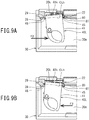
- use position retaining nails 20k are formed on a lower portion of the inner side surface of the recessed portion 21L into which the cup holder 40L is housed, as a cross section is illustrated in FIG. 5A .
- the use position retaining nails 20k are formed at two positions that are horizontally separated from each other and face the use position retaining nails 41k when the cup holder 40L is at the use position S described above.
- the use position retaining nails 20k elastically deform according to a rotational position of the cup holder 40L in an engageable and disengageable manner with and from the use position retaining nails 41k in a direction in which both use position retaining nails face each other.
- This configuration causes the use position retaining nails 41k of the cup holder 40L and the use position retaining nails 20k of the base panel 20 to engage with each other at the use position S and thereby enables the cup holder 40L to be retained at the use position S.
- This configuration also enables the passenger to, by holding appropriate portions of the cup holder 40L placed at the use position S and rotating the cup holder 40L toward the housed position side against a retaining force produced by elastic deformation of the use position retaining nails 41k, house the cup holder 40L to the housed position H.
- each of the cup holders 40L and 40R has, in a shaft-support structure of the cup holder, a "shaft-support portion fail-safe structure" disposed for preventing or inhibiting shaft-support components from being damaged when a load (moment) exceeding a predetermined level is exerted on the cup holder.
- a "shaft-support portion fail-safe structure" disposed for preventing or inhibiting shaft-support components from being damaged when a load (moment) exceeding a predetermined level is exerted on the cup holder.
- the cup holder 40L includes, as the two fulcrum shafts 45 and 46 described above, an outer side fulcrum shaft 46 disposed on the left side surface of the holder main body 41 and an inner side fulcrum shaft 45 disposed on the right side surface of the holder main body 41.
- the base panel 20 has two bearing portions 22 and 27 disposed coaxially with the axis CLh of the two fulcrum shafts 45 and 46.
- the inner side fulcrum shaft 45 and the outer side fulcrum shaft 46 are pivotally supported by the inner side bearing portion 22 on the axially inner side and the outer side bearing portion 27 on the axially outer side, respectively, in a rotatable manner.
- a bulging portion 28 bulging to the side where the table main body 30 is located is formed at a position facing the outer side surface of the holder main body 41, and, on the inner side surface of the bulging portion 28, a supporting hole 29 that supports the outer side fulcrum shaft 46 in a freely rotatable manner is formed and forms the outer side bearing portion 27.
- an annular boss portion 46t and an annular boss portion 45t are disposed on the left side surface of the holder main body 41 and the right side surface of the holder main body 41, respectively.
- the outer side fulcrum shaft 46 corresponding to the outer side bearing portion 27 has a shorter length than the inner side fulcrum shaft 45 corresponding to the inner side bearing portion 22, and the outer side fulcrum shaft 46 is inserted into the inside of the supporting hole 29 down to a vicinity of the opening portion of the supporting hole 29 (to a midway portion of the supporting hole 29).
- This configuration enables the outer side fulcrum shaft 46 to, when a load exceeding a predetermined level is exerted from the left side surface side (see F2 in FIGS. 1A and1B), easily engage and disengage with and from the supporting hole 29 through cooperation with the inner side bearing portion 22.
- a load of approximately 24.5 N to 49 N is assumed.
- the inner side bearing portion 22 is configured including a pair of supporting arms 23 and 25 that support the inner side fulcrum shaft 45 in a rotatable manner, as illustrated in FIGS. 2B and 6B .
- Each of the pair of supporting arms 23 and 25 projects from a lower portion of the front surface 21 of the base panel 20 in the direction perpendicular to the front surface 21 in a cantilever state.
- the first supporting arm 23 and the second supporting arm 25 are disposed on the axially outer side (the side where the holder main body 41 is located) and the axially inner side (the opposite side to the holder main body 41), respectively.
- a first bearing surface 24 that supports a base end side of the inner side fulcrum shaft 45 is disposed, and, on a tip end portion of the second supporting arm 25, a second bearing surface 26 that supports a tip end side of the inner side fulcrum shaft 45 is disposed coaxially with and in the same diameter as the first bearing surface 24.
- the first supporting arm 23 is formed in such a way as to have thickness (axial dimension) thinner than thickness (axial dimension) of the second supporting arm 25. This configuration enables the first supporting arm 23 to, when a load exceeding a predetermined level is exerted from the left side surface side (see F2 in FIGS. 1A and 1B ), elastically deform in the axial direction more easily than the second supporting arm 25.
- the pair of supporting arms 23 and 25 have slits 24s and 26s formed, respectively.
- the slits 24s and 26s on the side apart from the base panel 20, open portions of the peripheral portions of the respective bearing surfaces 24 and 26 along the axial direction and in the obliquely downward direction. This configuration causes the respective bearing surfaces 24 and 26 to have opening portions formed in the obliquely downward direction toward the side where the table mounting-surface 30m is located.
- opening widths (dimensions in a direction perpendicular to the axial direction) of the respective slits 24s and 26s are narrower than diameter of the inner side fulcrum shaft 45, the inner side fulcrum shaft 45 is supported in the respective bearing surfaces 24 and 26 and does not disengage through the slits 24s and 26s in a general use condition.
- pressing by the inner side fulcrum shaft 45 causes the pair of supporting arms 23 and 25 to elastically deform and the opening widths of the slits 24s and 26s to widen, which enables the inner side fulcrum shaft 45 to move in a direction in which the inner side fulcrum shaft 45 disengages from the respective bearing surfaces 24 and 26 through the slits 24s and 26s.
- a forming position (dimension in the direction perpendicular to the axial direction) of the first slit 24s of the first supporting arm 23 is set at a position at which the dimension thereof in the direction perpendicular to the axial direction is shorter than a forming position (dimension in the direction perpendicular to the axial direction) of the second slit 26s of the second supporting arm 25.
- This setting causes the opening width of the first bearing surface 24 by the first slit 24s to be wider than the opening width of the second bearing surface 26 by the second slit 26s.
- This configuration causes the inner side fulcrum shaft 45 to more easily disengage through the slit 24s of the first bearing surface 24 of the first supporting arm 23 than from the second bearing surface 26 of the second supporting arm 25 in any of a case in which a load exceeding a predetermined level is exerted from above (see F1 in FIGS. 1A and 1B ), a case in which a load exceeding a predetermined level is exerted from the left side surface side (see F2 in FIGS. 1A and 1B ), and a case in which a load exceeding a predetermined level is exerted backward (see F3 in FIGS. 1A and 1B ).
- the center cover 80 described above, as a main portion thereof is illustrated in FIG. 6B is mounted in such a way as to cover the whole of the inner side bearing portion 22 from the front side.
- engaging hooks 82 and 83 are disposed at four positions on upper and lower portions, as illustrated in FIG. 7 .
- the respective engaging hooks 82 and 83 are engaged with engaging holes 21u and 21d, illustrated in FIG. 2A , that are formed at positions on the front surface 21 of the base panel 20 that face the engaging hooks 82 and 83, in an attachable and detachable manner.
- the two lower engaging hooks 82 are disposed in upper vicinities of bulging portions 81, and the two upper engaging hooks 83 are disposed in a vicinity of an upper edge portion of the center cover 80. Separation distance between the two lower engaging hooks 82 is set to be larger than separation distance between the two upper engaging hooks 83.
- the upper engaging hooks 83 are arranged in such a way that an elastic displacement direction of the resin springs is aligned with the vertical direction, and the lower engaging hooks 82 are arranged in such a way that an elastic displacement direction of the resin springs is aligned with the horizontal direction.
- the center cover 80 is configured in such a way that the two lower engaging hooks 82 more easily disengage from the engaging holes 21d of the base panel 20 than the two upper engaging hooks 83. Retaining force by each lower engaging hook 82 of the center cover 80 is set in such a way that a pressing force corresponding to a load F3 as a load exceeding a predetermined level causes the engaging hook 82 to disengage from the corresponding engaging hole 21d.
- the center cover 80 has, on right and left lower portions thereof, the bulging portions 81 that are formed in such a manner as to bulge to the near side in the mounting direction.
- Each bulging portion 81 is disposed at a portion that covers the inner side bearing portion 22 when being mounted to the base panel 20.
- On the rear surface of each bulging portion 81 an inner peripheral surface 81n shaped in a concave circular arc is formed.
- the center cover 80 is mounted on the base panel 20 in such a way that the inner peripheral surface 81n of each bulging portion 81 faces an end portion of the slit 26s of the pair of supporting arms 23 and 25 with a slight gap interposed therebetween, as illustrated in FIG. 6B .
- the inner side fulcrum shaft 45 having moved is configured to press the inner peripheral surface 81n of the bulging portion 81 of the center cover 80 from the inner side and move the center cover 80 in a direction separating from the inner side bearing portion 22.
- the center cover 80 moving in the direction separating from the inner side bearing portion 22 because of the above configuration causes the inner side fulcrum shaft 45 to disengage from the inner side bearing portion 22.
- the folding table 10 of the present embodiment includes the hook unit 60 described above and the hinge mechanism 50 including cam bodies 51, a passenger is able to, by releasing the table main body 30 from retention by the hook unit 60 and hooking his/her fingers on a peripheral portion and the like of the table main body 30 and rotating the table main body 30 backward from the backrest, rotate the table main body 30 to a position at which the table main body 30 becomes substantially horizontal and thereby bring the table main body 30 to the use attitude U illustrated in FIG. 1A .
- the folding table 10 since only a passenger's rotating the table main body 30 manually in the closing direction or the opening direction by a predetermined angle causes the table main body 30 to subsequently rotate automatically by a biasing force of the coil spring 53 that the hinge mechanism 50 includes and a camming action of the two pairs of cam bodies 51, it is possible to easily perform opening and closing operation of the table main body 30.
- the state of the use attitude U in which the table main body 30 is opened, can be retained automatically without backlash by a biasing force of the coil spring 53 and a camming action of the two pairs of cam bodies 51.
- the folding table 10 includes two foldable cup holders 40L and 40R on the front surface 21 of the base panel 20, the passenger, by manually rotating one of the cup holders 40L and 40R to the use position S when the table main body 30 is in the use attitude U, can support a cup or similar article in the cup insertion portion K favorably.
- the folding table 10 of the present embodiment includes a "shaft-support portion fail-safe structure" in the shaft-support structures of the respective cup holders 40L and 40R, it is possible to make the fulcrum shafts 45 and 46 disengage from the bearing portions 22 and 27 when loads F1 to F4 exceeding a predetermined level and directed away from the base panel 20 are exerted on the left and right fulcrum shafts 45 and 46.
- shaft-support components such as the fulcrum shafts 45 and 46, of each of the cup holders 40L and 40R from being damaged.
- each of the cup holders 40L and 40R disposed to the folding table 10 enables shaft-support components, such as the fulcrum shafts 45 and 46, of each of the cup holders 40L and 40R to be more securely prevented or inhibited from being damaged according to loads F1 to F4 exerted from a plurality of directions as illustrated in FIG. 1A .
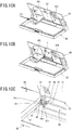
- the first supporting arm 23, which is disposed in conjunction with the second supporting arm 25, is pushed by the holder main body 41, as illustrated in FIGS. 10A to 10C .
- This pushing causes the first supporting arm 23 to elastically deform to the inner side and bend, and this bending causes the cup holder 40L to move to the side where the inner side bearing portion 22 is located, as illustrated in FIG. 10C . Since, as illustrated in FIG.
- this movement causes the short outer side fulcrum shaft 46, which fits into the supporting hole 29 of the outer side bearing portion 27, to disengage from the supporting hole 29, it is possible to prevent the shaft-support components, such as the fulcrum shafts 45 and 46, of the cup holder 40L from being damaged. Since adjustment of length of the outer side fulcrum shaft 46 enables timing at which the outer side fulcrum shaft 46 disengages from the supporting hole 29 to be changed easily, it is possible to easily perform adjustment of the amount of load causing the outer side fulcrum shaft 46 to disengage.
- the cup holder 40L is allowed to move in the rotational direction with the outer side fulcrum shaft 46 serving as a fulcrum due to effect of the short outer side fulcrum shaft 46, which fits into the supporting hole 29 of the outer side bearing portion 27, as illustrated in FIGS. 11A to 11C .
- the inner side fulcrum shaft 45 of the cup holder 40L disengages through the slits 24s and 26s, and, next, the inner side fulcrum shaft 45 comes into contact with the center cover 80, which covers the bearing portion 22 supporting the inner side fulcrum shaft 45, from the inside of the center cover 80, as illustrated in FIG. 11C . Since retaining force by the lower engaging hook 82 of the center cover 80 is set in such a way that the engaging hook 82 disengages from the engaging hole 21d by a pressing force corresponding to a load F3, the lower engaging hook 82 on a lower portion of the center cover 80 disengages from the engaging hole 21d.
- This disengagement causes the inner side fulcrum shaft 45 to disengage from the bearing portion 22, as illustrated in FIG. 9B , which enables the shaft-support components, such as the fulcrum shafts 45 and 46, of the cup holder 40L to be prevented from being damaged. Since adjustment of engagement force (for example, adjustment of engagement shapes, the amount of engagement, the amount of elastic deformation, and the like of a nail) of the lower engaging hook 82 disposed on a lower portion of the center cover 80 illustrated in FIG. 7 enables timing at which the inner side fulcrum shaft 45 disengages from the bearing portion 22 to be changed easily, it is possible to easily perform adjustment of the amount of load causing the inner side fulcrum shaft 45 to disengage.
- engagement force for example, adjustment of engagement shapes, the amount of engagement, the amount of elastic deformation, and the like of a nail
- the center cover 80 Since, for a load F3 exerted from the inner side in the lateral direction on the cup holder 40L, the center cover 80, by means of retaining force by the lower engaging hook 82 thereof, inhibits the inner side fulcrum shaft 45 from finally disengaging from the bearing portion 22, it is possible to, by reducing biding force exerted on the inner side fulcrum shaft 45 by the slits 24s and 26s by an amount that the retaining force by the lower engaging hook 82 of the center cover 80 shoulders, configure the inner side fulcrum shaft 45 to easily disengage through the slits 24s and 26s. Regarding adjustment of the amount of load causing the inner side fulcrum shaft 45 to disengage in this case, timing of the disengagement can also be easily changed by adjusting engagement force of the lower engaging hook 82 in a similar manner to the method described above.
- the inner side fulcrum shaft 45 can disengage through the slits 24s and 26s by the same mechanism of action as that when either load F2 or F3 is exerted.
- This action causes an expected fail-safe operation to work as illustrated in FIGS. 8A and 8B , which enables the shaft-support components, such as the fulcrum shafts 45 and 46, of the cup holder 40L to be prevented or inhibited from being damaged more securely.
- the shaft-support structures of the respective cup holders 40L and 40R disposed to the folding table 10 of the present embodiment enable the shaft-support components of the respective cup holders 40L and 40R to be more securely prevented or inhibited from being damaged when a load is exerted on the respective cup holders 40L and 40R.
- the shaft-support structure for a rotary body according to the present invention is applicable to, for example, a seat for a transportation means mounted on a transportation means other than a vehicle, such as a ship, a train, and an airplane.
- the shaft-support structure for a rotary body is applicable to various types of shaft-support structures as long as the shaft-support structure is, without limited to a cup holder of a folding table, a shaft-support structure that includes a bearing portion disposed to a base member and a fulcrum shaft that is disposed to a rotary body and supported by the bearing portion in a rotatable manner, in which, with respect to the base member, the rotary body is rotated about the fulcrum shaft to a first position and a second position.
- a cup holder of this type has a high necessity to be provided with the shaft-support structure because the cup holder is a site that a passenger is likely to hit and is suitable as a site to which the shaft-support portion fail-safe structure is applied.
- each of the cup holders 40L and 40R includes the first supporting arm 23 as a restricting portion that is disposed to the inner side bearing portion 22 of the two bearing portions 22 and 27 and is elastically deformable
- the present invention is not limited to the example.
- the first supporting arm 23, which functions as a restricting portion, may be disposed to either or both of the two bearing portions 22 and 27. Further, with regard to the bearing portion on the opposite side to the side where the first supporting arm(s) 23 is/are disposed, axial length of the fulcrum shaft corresponding to the opposite-side bearing portion may be shortened so that the fulcrum shaft disengages from the opposite-side bearing portion.
- the first supporting arm(s) 23 elastically deform(s) in such a way that the either of the cup holders 40L and 40R moves to the side where the first supporting arm(s) 23 is/are disposed, which enables the fulcrum shaft corresponding to the bearing portion on the opposite side to the side where the first supporting arm(s) 23 is/are disposed to disengage from the opposite-side bearing portion.
Description
- The present invention relates to a rotary body, the rotary body being a cup holder, with a shaft-support structure including a bearing portion disposed to a base member and a fulcrum shaft disposed to a rotary body and supported by the bearing portion in a rotatable manner, in which, with respect to the base member, the rotary body is rotated about the fulcrum shaft to a first position and a second position.
- As a rotary body with a shaft-support structure of this type, for example, a technology described in
PTL 1 is disclosed. In the technology described inPTL 1, when a load exceeding a predetermined level is exerted on a holder that is a rotary body, a fulcrum shaft of the holder climbing over a protrusion on an end portion of a guide groove that opens to the front side of a base member and disengaging from the guide groove causes a shaft-support component to be prevented from being damaged. Hereinafter, a structure for preventing or inhibiting a shaft-support component from being damaged in a shaft-support structure of this type is also referred to as a "shaft-support portion fail-safe structure". - PTL 1:
JP 3402417 B -
US 3, 389, 498 A describes features falling under the preamble ofclaim 1. - However, the shaft-support portion fail-safe structure described in
PTL 1 has a problem in that, since the fulcrum shaft is prevented from disengaging only by the protrusion disposed on an end portion of the guide groove, the amount of load causing the fulcrum shaft to disengage from the guide groove varies widely. Thus, there is a possibility that, depending on a degree of the variation, the fulcrum shaft of the holder easily disengages from the guide groove or is hard to disengage from the guide groove. Therefore, in the technology described inPTL 1, there is room for improvement in more securely preventing or inhibiting a shaft-support component, such as a fulcrum shaft of a holder, from being damaged when a load exceeding a predetermined level is exerted on a rotary body. - In the technology described in
PTL 1, there is also a problem in that, since an end portion of a guide groove opens at a position visible from the front side, a groove of a bearing portion is visible from the front side, which spoils external appearance. - Accordingly, the present invention has been made in view of such problems, and a problem to be solved by the present invention is to provide a shaft-support structure for a rotary body that is capable of more securely preventing or inhibiting a shaft-support component of a rotary body from being damaged when a load exceeding a predetermined level is exerted on the rotary body.
- The invention is defined by
claim 1. - In order to achieve the object mentioned above, according to an aspect of the present invention, there is provided a rotary body, the rotary body being a cup-holder, with a shaft-support structure, the shaft-support structure including: a bearing portion disposed to a base member; and a fulcrum shaft disposed to the rotary body and supported by the bearing portion in a rotatable manner, the rotary body being rotated with respect to the base member about the fulcrum shaft to a first position and a second position, the shaft-support structure including: a slit disposed to the bearing portion and opened in a direction away from the base member; and a restricting member disposed at a position facing the slit in such a way as to cover the slit, wherein the rotary body is configured in such a way that, when a load exceeding a predetermined level and directed away from the base member is exerted on the rotary body, the fulcrum shaft moves in a direction in which the fulcrum shaft disengages from inside the bearing portion through the slit and, by the fulcrum shaft having moved pressing the restricting member from inside and the restricting member moving in a direction separating from the bearing portion, the fulcrum shaft disengages from the bearing portion.
- In the rotary body with the shaft-support structure according to the one aspect of the present invention, since the fulcrum shaft disengages from the inside of the bearing portion when a load exceeding a predetermined level and directed away from the base member is exerted on the rotary body, it is possible to prevent or inhibit a portion, such as the fulcrum shaft, of the rotary body from being damaged.
- In particular, in the rotary body with the shaft-support structure according to the one aspect of the present invention, since the rotary body is configured in such a way that the fulcrum shaft moves in a direction in which the fulcrum shaft disengages from the bearing portion through the slit and, by the fulcrum shaft having moved pressing the restricting member and the restricting member moving in a direction separating from the bearing portion, the fulcrum shaft disengages from the inside of the bearing portion, it is possible to provide a shaft-support portion fail-safe structure that is capable of more securely preventing or inhibiting a shaft-support component, such as the fulcrum shaft, of the rotary body from being damaged through cooperation between the slit disposed to the bearing portion and the restricting member disposed in such a way as to cover the slit.
- In other words, the rotary body with the shaft-support structure according to the one aspect of the present invention enables the fulcrum shaft to be configured to easily disengage through the slit by reducing binding force by the slit by an amount that retaining force of the restricting member shoulders when compared with, for example, a shaft-support portion fail-safe structure disclosed in the
PTL 1 described above that prevents a fulcrum shaft from disengaging only by a protrusion disposed on an end portion of a guide groove. - Therefore, it is possible to control variation in the amount of load causing the fulcrum shaft to disengage from the bearing portion through the slit to be comparatively small. Since binding force by the slit can be reduced to be comparatively small, it is possible to reduce force exerted on the slit and the fulcrum shaft on the occasion when the fulcrum shaft disengages from the bearing portion through the slit. Thus the rotary body with the shaft-support structure according to the one aspect of the present invention excels as a shaft-support portion fail-safe structure that more securely prevents or inhibits a shaft-support component of a rotary body from being damaged. In addition, it is possible to manually place a rotary body that has disengaged back to a normal mounted state easily.
- In the rotary body with the shaft-support structure according to the one aspect of the present invention, since the restricting member is disposed at a position facing the slit in such a way as to cover the slit and the slit of the shaft-support portion is thereby concealed, it is also possible to improve external appearance quality.
- Further, in order to achieve the object mentioned above, according to another aspect of the present invention, there is provided a rotary body with a shaft-support structure, the shaft-support structure including: two bearing portions coaxially disposed to a base member; and two fulcrum shafts disposed on right and left side surfaces of the rotary body and respectively supported by the two bearing portions in a rotatable manner, the rotary body being rotated with respect to the base member about the two fulcrum shafts to a first position and a second position, the shaft-support structure including an elastically deformable restricting portion disposed to at least one bearing portion of the two bearing portions, wherein, when a load exceeding a predetermined level is exerted on the rotary body in a direction from the other bearing portion to the one bearing portion, the restricting portion is configured to elastically deform in such a way that the rotary body moves toward the one bearing portion and one of the two fulcrum shafts corresponding to the other bearing portion is configured to disengage from the other bearing portion.
- In the rotary body with the shaft-support structure according to the another aspect of the present invention, since a fulcrum shaft corresponding to the other bearing portion disengages from the other bearing portion when a load exceeding a predetermined level is exerted on the rotary body from the other bearing portion side to the one bearing portion side, it is possible to prevent or inhibit a shaft-support component, such as the fulcrum shaft, of the rotary body from being damaged.
- In particular, in the rotary body with the shaft-support structure according to the another aspect of the present invention, since the rotary body includes an elastically deformable restricting portion disposed to at least one bearing portion of the two bearing portions and, when a load exceeding a predetermined level is exerted on the rotary body from the other bearing portion side to the one bearing portion side, the restricting portion elastically deforms in such a way that the rotary body moves to the one bearing portion side and, therewith, a fulcrum shaft corresponding to the other bearing portion disengages from the other bearing portion, it is possible to provide a shaft-supporting portion fail-safe structure that is capable of, for a load exerted from a side of the rotary body, more securely preventing or inhibiting a shaft-support component, such as the fulcrum shaft, of the rotary body from being damaged through cooperation between the elastically deformable restricting portion disposed to the bearing portion and the fulcrum shaft that disengages from the bearing portion according to elastic deformation of the restricting portion.
- In other words, the rotary body with the shaft-support structure according to the another aspect of the present invention enables the fulcrum shaft to be configured to easily disengage from the other bearing portion by reducing a retaining margin for the other bearing portion retaining the fulcrum shaft of the rotary body by an amount that the amount of axial movement of the restricting portion due to elastic deformation shoulders when compared with, for example, the shaft-support portion fail-safe structure disclosed in the
PTL 1 described above that prevents a fulcrum shaft from disengaging only by a protrusion disposed on an end portion of a guide groove. In addition, it is possible to manually place a rotary body that has disengaged back to a normal mounted state easily. - Therefore, it is possible to control variation in the amount of load causing the fulcrum shaft to disengage from the inside of the other bearing portion to be comparatively small. In addition, effect of axial movement of the rotary body due to elastic deformation of the restricting portion enables binding force by the other bearing portion to be reduced to be comparatively small. Therefore, it is possible to reduce a load exerted on the other bearing portion and the fulcrum shaft on the occasion when the fulcrum shaft disengages from the inside of the other bearing portion. Thus, the shaft-support structure for a rotary body according to the another aspect of the present invention excels as a shaft-support portion fail-safe structure that more securely prevents or inhibits a shaft-support component of a rotary body from being damaged.
- As described above, the present invention can more securely prevent or inhibit a shaft-support component of a rotary body from being damaged when a load exceeding a predetermined level is exerted on the rotary body.
-
-
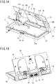
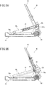
FIGS. 1A and 1B are perspective views descriptive of an embodiment of a folding table including a shaft-support structure for a rotary body according to one aspect of the present invention, andFIGS. 1A and 1B illustrate a use attitude in which a table main body is opened and the folding table inFIG. 1A viewed from the rear surface side, respectively; -
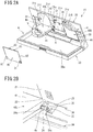
FIGS. 2A and 2B are perspective views descriptive of a shaft-support structure of a cup holder of the folding table illustrated inFIG. 1A , andFIG. 2A illustrates a state in which a cover body at the center of a base panel is removed andFIG. 2B is an enlarged view of a portion A inFIG. 2A ; -
FIGS. 3A and 3B are explanatory diagrams of the folding table illustrated inFIG. 1A , andFIGS. 3A and 3B are a diagram of the folding table viewed from a front and slightly obliquely upper direction and a front view thereof, respectively; -
FIG. 4 is a perspective view illustrative of a cup holder in a state of being removed from the base panel; -
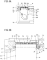
FIGS. 5A and 5B are diagrams descriptive of a shaft-support portion fail-safe structure of the cup holder, andFIGS. 5A and 5B are a cross-sectional view taken along the line Z-Z inFIG. 3B and a cross-sectional view taken along the line Y-Y inFIG. 3B , respectively; -
FIGS. 6A and 6B are diagrams descriptive of the shaft-support portion fail-safe structure of the cup holder, andFIG. 6A is a plan view of the cup holder at a use position illustrated with a main portion cross-sectioned andFIG. 6B is an enlarged view of a potion B inFIG. 6A ; -
FIG. 7 is a perspective view of the cover body in a state of being removed from the base panel when viewed from the rear surface side; -
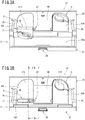
FIGS. 8A and 8B are diagrams descriptive of a fail-safe operation when a load exceeding a predetermined level is exerted on a fulcrum shaft portion of the cup holder, andFIGS. 8A and 8B correspond toFIGS. 5A and 5B , respectively, and illustrate a state when the fail-safe structure has worked; -
FIGS. 9A and 9B are diagrams descriptive of an operation when the fail-safe structure of the fulcrum shaft portion of the cup holder has worked, andFIGS 9A and 9B illustrate a fail-safe state when a load is exerted from the left side (outer side) and a fail-safe state when a load is exerted from the right side (inner side), respectively; -
FIGS. 10A to 10C are perspective views descriptive of an operation when the fail-safe structure of the fulcrum shaft portion of the cup holder has worked, andFIGS 10A, 10B, and 10C illustrate a fail-safe state when a load is exerted from the left side (outer side), the fail-safe state with the cover body at the center removed, and an enlarged view of a portion C inFIG. 10B , respectively; and -
FIGS. 11A to 11C are perspective views descriptive of an operation when the fail-safe structure of the fulcrum shaft portion of the cup holder has worked, andFIGS 11A, 11B, and 11C illustrate a fail-safe state when a load is exerted from the right side (inner side), the fail-safe state with the cover body at the center removed, and an enlarged view of a portion D inFIG. 11B , respectively. - Hereinafter, an embodiment of the present invention will be described with reference to the drawings as appropriate. A shaft-support structure for a rotary body of the present embodiment is an example of a shaft-support structure for a rotary body that is applied to a fulcrum shaft portion of a cup holder disposed to a folding table mounted on the back surface of the backrest of a seat for a vehicle.
- Note that the drawings are schematic. Therefore, it should be noted that a relation and ratio between thickness and planar dimensions, and the like are different from actual ones, and portions where dimensional relations and ratios are different from one another among the drawings are also included. In addition, the embodiment, which will be described below, indicates a device and method to embody a technical idea of the present invention, and the technical idea of the present invention does not limit materials, shapes, structures, arrangements, and the like of the constituent components to those described in the embodiment below.
- As illustrated in
FIGS. 1A and 1B , a folding table 10 of the present embodiment includes abase panel 20 and a tablemain body 30. Thebase panel 20 is a member that is made of plastic and is formed in a substantially rectangular shape in a plan view. On the rear surface of thebase panel 20, a reinforcing rib and a locking portion for holding thebase panel 20 to a backrest are formed at appropriate places (seeFIG. 1B ). On a lower portion of thebase panel 20, ahinge mechanism 50 that has a fulcrum axis CL extending horizontally in the vehicle width direction is disposed. - On the back surface of a not-illustrated backrest, a backrest finisher that is made of, for example, plastic is mounted, and the
base panel 20 has appropriate portions thereof fixed to the backrest finisher by fixing members, such as bolts and clamps, in such a way as to cover a recessed portion on an upper portion side of the backrest finisher. - The table
main body 30 is a member that is made of plastic and is formed in a substantially similar shape to the external shape of thebase panel 20 in a plan view. The tablemain body 30 has a base end portion thereof rotatably supported about the fulcrum axis CL at a lower end portion of thebase panel 20 and is rotatable from a use attitude U (FIG. 1A ) in which the tablemain body 30 is opened to a housed attitude (not illustrated) in which the tablemain body 30 is closed to the side where thebase panel 20 is located. In the present embodiment, in the use attitude U, the tablemain body 30 is deployed to a position at which a table mounting-surface 30m is substantially horizontal, as illustrated inFIG. 1A . - Although the table
main body 30 is set to have the table mounting-surface 30m positioned substantially horizontal in the use attitude U when the backrest of the seat for the vehicle is in a state of being arranged to a regular stand-up position, at which the backrest slightly inclines backward, a backrest generally has its inclination attitude adjustable by means of a reclining mechanism, as a result of which a horizontal state of the tablemain body 30 in the use attitude U varies according to a reclining angle. - When the table
main body 30 is in the housed attitude, in which the tablemain body 30 is closed to the side where thebase panel 20 is located, thebase panel 20 and the tablemain body 30 are hooked to each other by ahook unit 60, which has an engagement structure that is disposed on both members, as a result of which the housed attitude is retained. In the present embodiment, thehook unit 60, as an engagement structure disposed on both members described above, includes ahook 61 that is disposed at the middle of an upper edge portion of thebase panel 20 and anengagement hole 65 that is disposed at the middle of an upper edge portion of the tablemain body 30, as illustrated inFIG. 1A . On the tablemain body 30, apush button 66 on which a passenger manually performs a push-down operation to release engagement of thehook 61 is disposed. - When the table
main body 30 is in the housed attitude, thehook unit 60 is able to retain the tablemain body 30 in a state in which rotational motion thereof is restricted by elastically hooking thehook 61 to theengagement hole 65. Thehook unit 60 is configured to be able to, when the passenger pushes down thepush button 66, push down thehook 61 and releases thehook 61 from a state of being hooked to theengagement hole 65 and consequently release the engagement in thehook unit 60. - Further, in the present embodiment, the table
main body 30 is supported by thehinge mechanism 50, which connects the tablemain body 30 to thebase panel 20, in a manner enabling the tablemain body 30 to be rotated and to be retained and released in and from a plurality of attitudes with respect to thebase panel 20. - The
hinge mechanism 50, as a back surface portion thereof is illustrated inFIG. 1B , includes two pairs ofcam bodies 51 and acoil spring 53 as constituent members. The two pairs ofcam bodies 51 are arranged in an opposite manner to each other at horizontally symmetrical positions on both sides in the axial direction in a state of being biased to the outsides in the axial direction by thecoil spring 53 arranged at the middle. The constituent members of thehinge mechanism 50 are built into ahinge case 70, the constituent components of which are respectively formed in one body with thebase panel 20 and the tablemain body 30, from the back surface side of thehinge case 70. - The
hinge mechanism 50 is configured in such a way that, when the passenger manually rotates the tablemain body 30 relatively to thebase panel 20, each pair ofcam bodies 51 rotate relatively to each other to a predetermined angle by a biasing force of thecoil spring 53 and a camming action between the pair ofcam bodies 51. Further, thehinge mechanism 50 is configured in such a way that, at a position corresponding to the predetermined angle, concavo-convex shapes formed on cam surfaces of bothcam bodies 51 come into a predetermined state of engagement with each other and the tablemain body 30 can thereby be retained in an attitude in which the tablemain body 30 rotates relatively to thebase panel 20 by the predetermined angle. - Further, the folding table 10 has two
foldable cup holders front surface 21 of thebase panel 20 in a horizontally symmetrical manner, as illustrated inFIG. 1A . Between the twocup holders center cover 80 that is a covering body is mounted in an attachable and detachable manner. - Each of the
cup holders fulcrum shafts FIGS. 2A and 2B . Thecenter cover 80 is mounted in such a way as to cover a portion including the innerside fulcrum shafts 45 disposed on the middle sides between therespective cup holders base panel 20 to be kept in a good external appearance. - Each of the
cup holders base panel 20 in a rotatable manner about the right and leftfulcrum shafts cup holders base panel 20, individually rotate about an axis CLh (seeFIG. 3A ) of the right and leftfulcrum shafts - On the
front surface 21 of thebase panel 20, recessedportions right cup holders cup holders respective cup holders portions cup holders - Each of the
cup holders main body 30 is in the use attitude U, is rotated about the axis CLh of thefulcrum shafts surface 30m of the tablemain body 30, as illustrated inFIGS. 2A ,3A, and 3B , and serves a role of supporting a cup or similar article, such as a paper cup, a canned juice, and a beverage container. - The left and
right cup holders left cup holder 40L will be described and an illustration and a description of a detailed structure of theright cup holder 40R will be omitted. - As illustrated in
FIG. 4 , thecup holder 40L includes a holdermain body 41 that includes a fixedarm 42 and has a flat shape and a rotary arm 43 a base end portion of which is supported in a horizontally rotatable manner with respect to the holdermain body 41 and that has a hook shape. Therotary arm 43 is arranged facing the fixedarm 42 with a predetermined space allowing a cup or similar article to be supported interposed therebetween, and a portion in the predetermined space serves as a cup insertion portion K. Therotary arm 43 is biased toward the side where the fixedarm 42 is located by a not-illustrated spring built-in in abase end portion 43k. - The
rotary arm 43 of thecup holder 40L, at the use position S, horizontally rotated according to size of a cup or similar article that is inserted into the cup insertion portion K from above. Thus, thecup holder 40L enables, upon insertion of a cup or similar article into the cup insertion portion K, the cup or similar article, which has a different size, shape, and the like, to be held in the cup insertion portion K in a favorable manner. - On the left side surface, which faces the outer side, of the holder
main body 41, an engagingprotrusion 41t is disposed that elastically deforms in an advanceable and retractable manner in the width direction of the holdermain body 41. On the other hand, on thebase panel 20, an engaging recessedportion 21d that is capable of engaging and disengaging with and from the engagingprotrusion 41t is formed at a position that is on the inner side surface of the recessedportion 21L into which thecup holder 40L is housed and that faces the engagingprotrusion 41t when thecup holder 40L is at the housed position H, as illustrated inFIG. 2A . - This configuration causes the engaging
protrusion 41t of thecup holder 40L and the engaging recessedportion 21d of thebase panel 20 to engage with each other at the housed position H and thereby enables thecup holder 40L to be retained at the housed position H. This configuration also enables a passenger to, by holding appropriate portions of thecup holder 40L placed at the housed position H and pulling out thecup holder 40L toward himself/herself against a retaining force produced by elastic deformation of the engagingprotrusion 41t, rotate thecup holder 40L to the use position S. - Further, as illustrated in
FIG. 4 , on thecup holder 40L, useposition retaining nails 41k that are disposed in a protruding manner toward the side where thebase panel 20 is located are formed at two positions horizontally separated from each other on a substantially middle portion of the back end surface of a base end portion of the holdermain body 41. On the other hand, on thebase panel 20, useposition retaining nails 20k are formed on a lower portion of the inner side surface of the recessedportion 21L into which thecup holder 40L is housed, as a cross section is illustrated inFIG. 5A . - The use
position retaining nails 20k are formed at two positions that are horizontally separated from each other and face the useposition retaining nails 41k when thecup holder 40L is at the use position S described above. The useposition retaining nails 20k elastically deform according to a rotational position of thecup holder 40L in an engageable and disengageable manner with and from the useposition retaining nails 41k in a direction in which both use position retaining nails face each other. - This configuration causes the use
position retaining nails 41k of thecup holder 40L and the useposition retaining nails 20k of thebase panel 20 to engage with each other at the use position S and thereby enables thecup holder 40L to be retained at the use position S. This configuration also enables the passenger to, by holding appropriate portions of thecup holder 40L placed at the use position S and rotating thecup holder 40L toward the housed position side against a retaining force produced by elastic deformation of the useposition retaining nails 41k, house thecup holder 40L to the housed position H. - In the present embodiment, each of the
cup holders cup holder 40L will be illustrated and described and an illustration and a description of thecup holder 40R will be omitted. - As illustrated in
FIGS. 6A and 6B , thecup holder 40L includes, as the twofulcrum shafts side fulcrum shaft 46 disposed on the left side surface of the holdermain body 41 and an innerside fulcrum shaft 45 disposed on the right side surface of the holdermain body 41. On the other hand, thebase panel 20 has two bearingportions fulcrum shafts side fulcrum shaft 45 and the outerside fulcrum shaft 46 are pivotally supported by the innerside bearing portion 22 on the axially inner side and the outerside bearing portion 27 on the axially outer side, respectively, in a rotatable manner. - As illustrated in an enlarged manner in
FIG. 6B , on thefront surface 21 of the base panel, a bulgingportion 28 bulging to the side where the tablemain body 30 is located is formed at a position facing the outer side surface of the holdermain body 41, and, on the inner side surface of the bulgingportion 28, a supportinghole 29 that supports the outerside fulcrum shaft 46 in a freely rotatable manner is formed and forms the outerside bearing portion 27. To a base end portion of the outerside fulcrum shaft 46 and a base end portion of the innerside fulcrum shaft 45, anannular boss portion 46t and anannular boss portion 45t are disposed on the left side surface of the holdermain body 41 and the right side surface of the holdermain body 41, respectively. - The outer
side fulcrum shaft 46 corresponding to the outerside bearing portion 27 has a shorter length than the innerside fulcrum shaft 45 corresponding to the innerside bearing portion 22, and the outerside fulcrum shaft 46 is inserted into the inside of the supportinghole 29 down to a vicinity of the opening portion of the supporting hole 29 (to a midway portion of the supporting hole 29). This configuration enables the outerside fulcrum shaft 46 to, when a load exceeding a predetermined level is exerted from the left side surface side (see F2 inFIGS. 1A and1B), easily engage and disengage with and from the supportinghole 29 through cooperation with the innerside bearing portion 22. As the load exceeding a predetermined level, for example, a load of approximately 24.5 N to 49 N is assumed. - On the other hand, the inner
side bearing portion 22 is configured including a pair of supportingarms side fulcrum shaft 45 in a rotatable manner, as illustrated inFIGS. 2B and6B . Each of the pair of supportingarms front surface 21 of thebase panel 20 in the direction perpendicular to thefront surface 21 in a cantilever state. Of the pair of supportingarms arm 23 and the second supportingarm 25 are disposed on the axially outer side (the side where the holdermain body 41 is located) and the axially inner side (the opposite side to the holder main body 41), respectively. - On a tip end portion of the first supporting
arm 23, afirst bearing surface 24 that supports a base end side of the innerside fulcrum shaft 45 is disposed, and, on a tip end portion of the second supportingarm 25, asecond bearing surface 26 that supports a tip end side of the innerside fulcrum shaft 45 is disposed coaxially with and in the same diameter as thefirst bearing surface 24. The first supportingarm 23 is formed in such a way as to have thickness (axial dimension) thinner than thickness (axial dimension) of the second supportingarm 25. This configuration enables the first supportingarm 23 to, when a load exceeding a predetermined level is exerted from the left side surface side (see F2 inFIGS. 1A and 1B ), elastically deform in the axial direction more easily than the second supportingarm 25. - Further, the pair of supporting
arms slits slits base panel 20, open portions of the peripheral portions of the respective bearing surfaces 24 and 26 along the axial direction and in the obliquely downward direction. This configuration causes the respective bearing surfaces 24 and 26 to have opening portions formed in the obliquely downward direction toward the side where the table mounting-surface 30m is located. - Since opening widths (dimensions in a direction perpendicular to the axial direction) of the
respective slits side fulcrum shaft 45, the innerside fulcrum shaft 45 is supported in the respective bearing surfaces 24 and 26 and does not disengage through theslits base panel 20 is exerted, pressing by the innerside fulcrum shaft 45 causes the pair of supportingarms slits side fulcrum shaft 45 to move in a direction in which the innerside fulcrum shaft 45 disengages from the respective bearing surfaces 24 and 26 through theslits - As illustrated in
FIGS 2B and6B , a forming position (dimension in the direction perpendicular to the axial direction) of thefirst slit 24s of the first supportingarm 23 is set at a position at which the dimension thereof in the direction perpendicular to the axial direction is shorter than a forming position (dimension in the direction perpendicular to the axial direction) of thesecond slit 26s of the second supportingarm 25. This setting causes the opening width of thefirst bearing surface 24 by thefirst slit 24s to be wider than the opening width of thesecond bearing surface 26 by thesecond slit 26s. - This configuration causes the inner
side fulcrum shaft 45 to more easily disengage through theslit 24s of thefirst bearing surface 24 of the first supportingarm 23 than from thesecond bearing surface 26 of the second supportingarm 25 in any of a case in which a load exceeding a predetermined level is exerted from above (see F1 inFIGS. 1A and 1B ), a case in which a load exceeding a predetermined level is exerted from the left side surface side (see F2 inFIGS. 1A and 1B ), and a case in which a load exceeding a predetermined level is exerted backward (see F3 inFIGS. 1A and 1B ). - Further, the
center cover 80 described above, as a main portion thereof is illustrated inFIG. 6B , is mounted in such a way as to cover the whole of the innerside bearing portion 22 from the front side. On the rear surface of thecenter cover 80, engaginghooks FIG. 7 . The respectiveengaging hooks holes FIG. 2A , that are formed at positions on thefront surface 21 of thebase panel 20 that face the engaginghooks - The two lower
engaging hooks 82 are disposed in upper vicinities of bulgingportions 81, and the two upper engaginghooks 83 are disposed in a vicinity of an upper edge portion of thecenter cover 80. Separation distance between the two lowerengaging hooks 82 is set to be larger than separation distance between the two upper engaging hooks 83. The upperengaging hooks 83 are arranged in such a way that an elastic displacement direction of the resin springs is aligned with the vertical direction, and the lowerengaging hooks 82 are arranged in such a way that an elastic displacement direction of the resin springs is aligned with the horizontal direction. - Because of this configuration, the
center cover 80 is configured in such a way that the two lowerengaging hooks 82 more easily disengage from the engagingholes 21d of thebase panel 20 than the two upper engaging hooks 83. Retaining force by each lower engaginghook 82 of thecenter cover 80 is set in such a way that a pressing force corresponding to a load F3 as a load exceeding a predetermined level causes the engaginghook 82 to disengage from the corresponding engaginghole 21d. - The
center cover 80 has, on right and left lower portions thereof, the bulgingportions 81 that are formed in such a manner as to bulge to the near side in the mounting direction. Each bulgingportion 81 is disposed at a portion that covers the innerside bearing portion 22 when being mounted to thebase panel 20. On the rear surface of each bulgingportion 81, an innerperipheral surface 81n shaped in a concave circular arc is formed. Thecenter cover 80 is mounted on thebase panel 20 in such a way that the innerperipheral surface 81n of each bulgingportion 81 faces an end portion of theslit 26s of the pair of supportingarms FIG. 6B . - Because of the configuration described thus far, when a load exceeding a predetermined level and directed away from the base panel 20 (see F1 to F4 in
FIGS. 1A and 1B ) is exerted on thecup holder 40L, the innerside fulcrum shaft 45 moves in a direction in which the innerside fulcrum shaft 45 disengages from the inside of the innerside bearing portion 22 through theslits - Further, the inner
side fulcrum shaft 45 having moved is configured to press the innerperipheral surface 81n of the bulgingportion 81 of thecenter cover 80 from the inner side and move thecenter cover 80 in a direction separating from the innerside bearing portion 22. Thecenter cover 80 moving in the direction separating from the innerside bearing portion 22 because of the above configuration causes the innerside fulcrum shaft 45 to disengage from the innerside bearing portion 22. - Next, operation and operational effects of the folding table 10 described above will be described.
- Since the folding table 10 of the present embodiment includes the
hook unit 60 described above and thehinge mechanism 50 includingcam bodies 51, a passenger is able to, by releasing the tablemain body 30 from retention by thehook unit 60 and hooking his/her fingers on a peripheral portion and the like of the tablemain body 30 and rotating the tablemain body 30 backward from the backrest, rotate the tablemain body 30 to a position at which the tablemain body 30 becomes substantially horizontal and thereby bring the tablemain body 30 to the use attitude U illustrated inFIG. 1A . - In addition, since manually rotating the table
main body 30 forward from the use attitude U and thereby bringing the tablemain body 30 back to the housed attitude in which the tablemain body 30 is closed to the backrest side cause the tablemain body 30 to be hooked to thebase panel 20 by thehook unit 60, the passenger is able to close the tablemain body 30. - In other words, according to the folding table 10, since only a passenger's rotating the table
main body 30 manually in the closing direction or the opening direction by a predetermined angle causes the tablemain body 30 to subsequently rotate automatically by a biasing force of thecoil spring 53 that thehinge mechanism 50 includes and a camming action of the two pairs ofcam bodies 51, it is possible to easily perform opening and closing operation of the tablemain body 30. In addition, the state of the use attitude U, in which the tablemain body 30 is opened, can be retained automatically without backlash by a biasing force of thecoil spring 53 and a camming action of the two pairs ofcam bodies 51. - Since the folding table 10 includes two
foldable cup holders front surface 21 of thebase panel 20, the passenger, by manually rotating one of thecup holders main body 30 is in the use attitude U, can support a cup or similar article in the cup insertion portion K favorably. - In particular, since the folding table 10 of the present embodiment includes a "shaft-support portion fail-safe structure" in the shaft-support structures of the
respective cup holders fulcrum shafts portions base panel 20 are exerted on the left andright fulcrum shafts fulcrum shafts cup holders - That is, the shaft-support structure of each of the
cup holders fulcrum shafts cup holders FIG. 1A . In addition, it is possible to manually place each of thecup holders - Specifically, according to the shaft-support structure of each of the
cup holders cup holder 40L, the first supportingarm 23, which is disposed in conjunction with the second supportingarm 25, is pushed by the holdermain body 41, as illustrated inFIGS. 10A to 10C . This pushing causes the first supportingarm 23 to elastically deform to the inner side and bend, and this bending causes thecup holder 40L to move to the side where the innerside bearing portion 22 is located, as illustrated inFIG. 10C . Since, as illustrated inFIG. 9A , this movement causes the short outerside fulcrum shaft 46, which fits into the supportinghole 29 of the outerside bearing portion 27, to disengage from the supportinghole 29, it is possible to prevent the shaft-support components, such as thefulcrum shafts cup holder 40L from being damaged. Since adjustment of length of the outerside fulcrum shaft 46 enables timing at which the outerside fulcrum shaft 46 disengages from the supportinghole 29 to be changed easily, it is possible to easily perform adjustment of the amount of load causing the outerside fulcrum shaft 46 to disengage. Since adjustment of the amount of elastic deformation is easily performed through adjustment of thickness or the like of the first supportingarm 23, it is also possible to easily perform adjustment of the amount of load causing the outerside fulcrum shaft 46 to disengage through adjustment of the amount of bending of the first supportingarm 23. - Further, according to the shaft-support structure of each of the
cup holders cup holder 40L, thecup holder 40L is allowed to move in the rotational direction with the outerside fulcrum shaft 46 serving as a fulcrum due to effect of the short outerside fulcrum shaft 46, which fits into the supportinghole 29 of the outerside bearing portion 27, as illustrated inFIGS. 11A to 11C . - Therefore, the inner
side fulcrum shaft 45 of thecup holder 40L disengages through theslits side fulcrum shaft 45 comes into contact with thecenter cover 80, which covers the bearingportion 22 supporting the innerside fulcrum shaft 45, from the inside of thecenter cover 80, as illustrated inFIG. 11C . Since retaining force by the lower engaginghook 82 of thecenter cover 80 is set in such a way that the engaginghook 82 disengages from the engaginghole 21d by a pressing force corresponding to a load F3, the lower engaginghook 82 on a lower portion of thecenter cover 80 disengages from the engaginghole 21d. - This disengagement causes the inner
side fulcrum shaft 45 to disengage from the bearingportion 22, as illustrated inFIG. 9B , which enables the shaft-support components, such as thefulcrum shafts cup holder 40L to be prevented from being damaged. Since adjustment of engagement force (for example, adjustment of engagement shapes, the amount of engagement, the amount of elastic deformation, and the like of a nail) of the lower engaginghook 82 disposed on a lower portion of thecenter cover 80 illustrated inFIG. 7 enables timing at which the innerside fulcrum shaft 45 disengages from the bearingportion 22 to be changed easily, it is possible to easily perform adjustment of the amount of load causing the innerside fulcrum shaft 45 to disengage. - Since, for a load F3 exerted from the inner side in the lateral direction on the
cup holder 40L, thecenter cover 80, by means of retaining force by the lower engaginghook 82 thereof, inhibits the innerside fulcrum shaft 45 from finally disengaging from the bearingportion 22, it is possible to, by reducing biding force exerted on the innerside fulcrum shaft 45 by theslits hook 82 of thecenter cover 80 shoulders, configure the innerside fulcrum shaft 45 to easily disengage through theslits side fulcrum shaft 45 to disengage in this case, timing of the disengagement can also be easily changed by adjusting engagement force of the lower engaginghook 82 in a similar manner to the method described above. - Further, according to the shaft-support structure of each of the
cup holders cup holder 40L and a load F4 directed backward away from thebase panel 20, bias also occurs on points of exertion of the loads F1 and F4 on thefulcrum shafts - Therefore, when the load F1 or F4 is exerted on each of the
cup holders FIGS. 5A and 5B , the innerside fulcrum shaft 45 can disengage through theslits FIGS. 8A and 8B , which enables the shaft-support components, such as thefulcrum shafts cup holder 40L to be prevented or inhibited from being damaged more securely. - Furthermore, according to the shaft-support structure of each of the
cup holders center cover 80 is disposed in such a way as to cover the two supportingarms side bearing portion 22, it is possible to improve external appearance quality of the folding table 10. - As described thus far, the shaft-support structures of the
respective cup holders respective cup holders respective cup holders - For example, although, in the embodiment described above, an example of applying a shaft-support structure for a rotary body according to the present invention to the
cup holders - That is, as long as applied to a cup holder of a folding table, the shaft-support structure for a rotary body according to the present invention is applicable to, for example, a seat for a transportation means mounted on a transportation means other than a vehicle, such as a ship, a train, and an airplane.
- It is obvious that the shaft-support structure for a rotary body according to the present invention is applicable to various types of shaft-support structures as long as the shaft-support structure is, without limited to a cup holder of a folding table, a shaft-support structure that includes a bearing portion disposed to a base member and a fulcrum shaft that is disposed to a rotary body and supported by the bearing portion in a rotatable manner, in which, with respect to the base member, the rotary body is rotated about the fulcrum shaft to a first position and a second position.
- However, when the rotary body is a cup holder of a folding table mounted on the backrest of a seat for a vehicle, a cup holder of this type has a high necessity to be provided with the shaft-support structure because the cup holder is a site that a passenger is likely to hit and is suitable as a site to which the shaft-support portion fail-safe structure is applied.
- In addition, although, in the embodiment described above, an example in which, for example, each of the
cup holders arm 23 as a restricting portion that is disposed to the innerside bearing portion 22 of the two bearingportions - That is, the first supporting
arm 23, which functions as a restricting portion, may be disposed to either or both of the two bearingportions - Even with such a configuration, when a load exceeding a predetermined level is exerted on either of the
cup holders portions cup holders -
- 10
- Folding table
- 20
- Base panel(base member)
- 21
- Front surface of the base panel
- 22
- Inner side bearing portion (bearing portion)
- 23
- First supporting arm (restricting portion)
- 24
- First bearing surface
- 24s
- First slit
- 25
- Second supporting arm
- 26
- Second bearing surface
- 26s
- Second slit
- 27
- Outer side bearing portion (bearing portion)
- 28
- Bulging portion
- 29
- Supporting hole
- 30
- Table main body
- 30m
- Table mounting-surface
- 40L, 40R
- Cup holder (rotary body)
- 41
- Holder main body
- 42
- Fixed arm
- 43
- Rotary arm
- 44
- Attitude retaining nail
- 45
- Inner side fulcrum shaft (fulcrum shaft)
- 46
- Outer side fulcrum shaft (fulcrum shaft)
- 50
- Hinge mechanism
- 51
- Cam body pair
- 53
- Coil spring
- 60
- Hook unit
- 61
- Hook
- 65
- Engagement hole
- 66
- Push button
- 70
- Hinge case
- 80
- Center cover (restricting member, cover body)
- 81
- Bulging portion
- 82
- Lower engaging hook
- 83
- Upper engaging hook
- CL
- Fulcrum axis
- CLh
- Holder fulcrum axis
- U
- Use attitude
- K
- Cup insertion portion
Claims (5)
- A rotary body (10), the rotary body being a cup holder, with a shaft-support structure for said rotary body (10), the shaft-support structure comprising: a bearing portion (22) disposed to a base member (20) ; and a fulcrum shaft (45, 46) disposed to the rotary body and supported by the bearing portion in a rotatable manner, the rotary body being rotatable with respect to the base member (20) about the fulcrum shaft to a first position and a second position, the shaft-support structure comprising:a slit (24s) disposed to the bearing portion and opened in a direction away from the base member; and characterized bya restricting member (80) disposed at a position facing the slit in such a way as to cover the slit,wherein the rotary body is configured in such a way that, when a load exceeding a predetermined level and directed away from the base member is exerted on the rotary body (10), the fulcrum shaft (45, 46) moves in a direction in which the fulcrum shaft disengages from inside the bearing portion through the slit and, by the fulcrum shaft having moved pressing the restricting member from inside and the restricting member moving in a direction separating from the bearing portion, the fulcrum shaft disengages from the bearing portion, whereinthe rotary body is adapted for a folding table mounted on a backrest of a seat for a vehicle.
- The rotary body according to claim 1, wherein
the restricting member (80) is a cover body covering the bearing portion and is retained to the base member in an attachable and detachable manner. - The rotary body of one of the preceding claims,, the shaft-support structure comprising: two bearing portions coaxially disposed to a base member; and two fulcrum shafts disposed on right and left side surfaces of the rotary body and respectively supported by the two bearing portions in a rotatable manner, the rotary body being rotatable with respect to the base member about the two fulcrum shafts to a first position and a second position, the shaft-support structure comprising
an elastically deformable restricting portion (23) disposed to at least one bearing portion of the two bearing portions,
wherein, when a load exceeding a predetermined level is exerted on the rotary body in a direction from the other bearing portion to the one bearing portion, the restricting portion is configured to elastically deform in such a way that the rotary body moves toward the one bearing portion and one of the two fulcrum shafts corresponding to the other bearing portion is configured to disengage from the other bearing portion. - The rotary body according to claim 3 further comprising
a cover body configured to cover the one bearing portion and the restricting portion. - The rotary body according to claim 3 or 4, wherein
a fulcrum shaft corresponding to the other bearing portion has an axial length shorter than a fulcrum shaft corresponding to the one bearing portion
Applications Claiming Priority (2)
| Application Number | Priority Date | Filing Date | Title |
|---|---|---|---|
| JP2016140679A JP6663318B2 (en) | 2016-07-15 | 2016-07-15 | Rotor support structure |
| PCT/JP2017/022667 WO2018012218A1 (en) | 2016-07-15 | 2017-06-20 | Shaft-support structure for rotary body |
Publications (3)
| Publication Number | Publication Date |
|---|---|
| EP3486509A1 EP3486509A1 (en) | 2019-05-22 |
| EP3486509A4 EP3486509A4 (en) | 2019-07-24 |
| EP3486509B1 true EP3486509B1 (en) | 2021-04-14 |
Family
ID=60953060
Family Applications (1)
| Application Number | Title | Priority Date | Filing Date |
|---|---|---|---|
| EP17827348.8A Active EP3486509B1 (en) | 2016-07-15 | 2017-06-20 | Shaft-support structure for rotary body |
Country Status (6)
| Country | Link |
|---|---|
| US (1) | US11084409B2 (en) |
| EP (1) | EP3486509B1 (en) |
| JP (1) | JP6663318B2 (en) |
| KR (1) | KR102143303B1 (en) |
| CN (1) | CN109416073B (en) |
| WO (1) | WO2018012218A1 (en) |
Families Citing this family (2)
| Publication number | Priority date | Publication date | Assignee | Title |
|---|---|---|---|---|
| US11046229B1 (en) * | 2019-11-27 | 2021-06-29 | Elizabeth Brooke Natwick | Cup holder |
| US20230415629A1 (en) * | 2022-06-27 | 2023-12-28 | B/E Aerospace, Inc. | Deployable elastomeric bottle holster |
Family Cites Families (21)
| Publication number | Priority date | Publication date | Assignee | Title |
|---|---|---|---|---|
| US1332086A (en) * | 1919-01-14 | 1920-02-24 | Irving N Van Sickles | Broom-holder |
| US3233277A (en) * | 1963-05-29 | 1966-02-08 | Jaylis Ind Inc | Hinge |
| US3389497A (en) * | 1965-12-28 | 1968-06-25 | King Seeley Thermos Co | Plastic axle bearings for use on toy vehicles |
| US3389498A (en) * | 1965-12-28 | 1968-06-25 | King Seeley Thermos Co | Plastic axle bearings for use on toy vehicles |
| US3389496A (en) * | 1965-12-28 | 1968-06-25 | King Seeley Thermos Co | Plastic axle bearings for use on toy vehicles |
| US3402417A (en) | 1966-11-17 | 1968-09-24 | Ordell R. Lund | Paint applicator |
| JPS5153498Y2 (en) | 1974-05-09 | 1976-12-21 | ||
| JPS58127315U (en) * | 1982-02-23 | 1983-08-29 | カルソニックカンセイ株式会社 | shaft mounting device |
| JPS59199978A (en) * | 1983-04-27 | 1984-11-13 | 富士通テン株式会社 | Door attaching structure |
| JPH01142751U (en) | 1988-03-25 | 1989-09-29 | ||
| JPH0545180U (en) * | 1989-04-21 | 1993-06-18 | 株式会社ケンウツド | Cassette door mounting mechanism |
| JPH0628524Y2 (en) * | 1989-04-28 | 1994-08-03 | カシオ計算機株式会社 | Rotating member shaft support structure |
| JP3402417B2 (en) * | 1995-05-25 | 2003-05-06 | ダイハツ工業株式会社 | Vehicle cup holder device |
| US6116806A (en) * | 1999-02-17 | 2000-09-12 | Chang; Chin Pao | Connection tightness and swing angle adjustable pivot |
| JP2002368444A (en) * | 2001-06-11 | 2002-12-20 | Matsushita Electric Ind Co Ltd | Door hinge device of electronic equipment housing enclosure |
| JP4615387B2 (en) * | 2005-07-19 | 2011-01-19 | 株式会社パイオラックス | Stay structure |
| TWM345150U (en) * | 2008-06-12 | 2008-11-21 | Protorsion Hinge Co Ltd | Pivot structure for auxiliary positioning of washer |
| JP5577146B2 (en) | 2010-04-22 | 2014-08-20 | 株式会社ニフコ | Cup holder |
| DE102010022442A1 (en) * | 2010-06-01 | 2011-12-01 | Volkswagen Ag | Attachment device e.g. armrest, for inner space of motor car, to receive drink container i.e. bottle, has rotary bearing moved away in axial direction of shaft during event of overload when attachment is pivoted around pivotal axis |
| JP6167980B2 (en) | 2014-04-11 | 2017-07-26 | トヨタ紡織株式会社 | Vehicle seat table |
| JP6721441B2 (en) * | 2016-07-14 | 2020-07-15 | 株式会社ニフコ | Table unit |
-
2016
- 2016-07-15 JP JP2016140679A patent/JP6663318B2/en active Active
-
2017
- 2017-06-20 CN CN201780040352.1A patent/CN109416073B/en active Active
- 2017-06-20 KR KR1020197000719A patent/KR102143303B1/en active IP Right Grant
- 2017-06-20 EP EP17827348.8A patent/EP3486509B1/en active Active
- 2017-06-20 US US16/316,761 patent/US11084409B2/en active Active
- 2017-06-20 WO PCT/JP2017/022667 patent/WO2018012218A1/en unknown
Non-Patent Citations (1)
| Title |
|---|
| None * |
Also Published As
| Publication number | Publication date |
|---|---|
| CN109416073B (en) | 2020-12-18 |
| WO2018012218A1 (en) | 2018-01-18 |
| KR20190016566A (en) | 2019-02-18 |
| KR102143303B1 (en) | 2020-08-10 |
| US11084409B2 (en) | 2021-08-10 |
| EP3486509A4 (en) | 2019-07-24 |
| JP6663318B2 (en) | 2020-03-11 |
| JP2018009681A (en) | 2018-01-18 |
| US20190232848A1 (en) | 2019-08-01 |
| CN109416073A (en) | 2019-03-01 |
| EP3486509A1 (en) | 2019-05-22 |
Similar Documents
| Publication | Publication Date | Title |
|---|---|---|
| CN202966024U (en) | Seat adjusting device for vehicles | |
| US9849819B2 (en) | Hidden foldable tray table | |
| US20170174146A1 (en) | Adjustable mobile-device holder | |
| US9187011B2 (en) | Vehicle seat provided with means for attaching a removable tray | |
| EP3666650B1 (en) | Deployable portable electronic device holder for aircraft seat | |
| EP3486117B1 (en) | Table unit | |
| US10155483B2 (en) | Vehicle interior component | |
| US20070145791A1 (en) | Locking device for a tray table system in a seat, in particular an aircraft passenger seat | |
| EP3486509B1 (en) | Shaft-support structure for rotary body | |
| US9290112B2 (en) | Vehicle seat provided with a removable tray | |
| EP3230162B1 (en) | Retractable device holder for an aircraft seat | |
| ITTO20130453A1 (en) | SUPPORT AND HOLDING GROUP FOR A PORTABLE ELECTRONIC DEVICE, AND VEHICLE DASHBOARD PROVIDED WITH SUCH SUPPORT AND HOLDING GROUP | |
| CN107531327A (en) | For the holding meanss of the portable set of aircraft seat | |
| EP2639103A1 (en) | Seat-supported stowable tray table provided with a hinged stand | |
| US10981482B2 (en) | Portable table attachable and detachable from the interior trim of a vehicle | |
| WO2017087602A1 (en) | Integral tray table personal electronic device holder and tray table | |
| WO2014049072A1 (en) | Securing system, retaining device and portable mounting adapter for passenger appliances in an aircraft | |
| US9688172B2 (en) | Foldable head rest assembly | |
| EP3383700B1 (en) | Latch mechanism | |
| JP2016199068A (en) | Turning member | |
| EP4201736A1 (en) | Safety seat | |
| US11473345B2 (en) | Vehicle hood locking mechanism | |
| CN210821943U (en) | Table, seat and vehicle | |
| CN210852164U (en) | On-vehicle little table plate structure and vehicle | |
| JPH0661594U (en) | Seat armrests |
Legal Events
| Date | Code | Title | Description |
|---|---|---|---|
| STAA | Information on the status of an ep patent application or granted ep patent |
Free format text: STATUS: THE INTERNATIONAL PUBLICATION HAS BEEN MADE |
|
| PUAI | Public reference made under article 153(3) epc to a published international application that has entered the european phase |
Free format text: ORIGINAL CODE: 0009012 |
|
| STAA | Information on the status of an ep patent application or granted ep patent |
Free format text: STATUS: REQUEST FOR EXAMINATION WAS MADE |
|
| 17P | Request for examination filed |
Effective date: 20190109 |
|
| AK | Designated contracting states |
Kind code of ref document: A1 Designated state(s): AL AT BE BG CH CY CZ DE DK EE ES FI FR GB GR HR HU IE IS IT LI LT LU LV MC MK MT NL NO PL PT RO RS SE SI SK SM TR |
|
| AX | Request for extension of the european patent |
Extension state: BA ME |
|
| A4 | Supplementary search report drawn up and despatched |
Effective date: 20190626 |
|
| RIC1 | Information provided on ipc code assigned before grant |
Ipc: F16C 35/02 20060101ALI20190619BHEP Ipc: F16C 11/04 20060101AFI20190619BHEP Ipc: B60N 3/10 20060101ALI20190619BHEP |
|
| DAV | Request for validation of the european patent (deleted) | ||
| DAX | Request for extension of the european patent (deleted) | ||
| GRAP | Despatch of communication of intention to grant a patent |
Free format text: ORIGINAL CODE: EPIDOSNIGR1 |
|
| STAA | Information on the status of an ep patent application or granted ep patent |
Free format text: STATUS: GRANT OF PATENT IS INTENDED |
|
| INTG | Intention to grant announced |
Effective date: 20210118 |
|
| GRAS | Grant fee paid |
Free format text: ORIGINAL CODE: EPIDOSNIGR3 |
|
| GRAA | (expected) grant |
Free format text: ORIGINAL CODE: 0009210 |
|
| STAA | Information on the status of an ep patent application or granted ep patent |
Free format text: STATUS: THE PATENT HAS BEEN GRANTED |
|
| AK | Designated contracting states |
Kind code of ref document: B1 Designated state(s): AL AT BE BG CH CY CZ DE DK EE ES FI FR GB GR HR HU IE IS IT LI LT LU LV MC MK MT NL NO PL PT RO RS SE SI SK SM TR |
|
| REG | Reference to a national code |
Ref country code: GB Ref legal event code: FG4D |
|
| REG | Reference to a national code |
Ref country code: CH Ref legal event code: EP |
|
| REG | Reference to a national code |
Ref country code: DE Ref legal event code: R096 Ref document number: 602017036824 Country of ref document: DE |
|
| REG | Reference to a national code |
Ref country code: IE Ref legal event code: FG4D |
|
| REG | Reference to a national code |
Ref country code: AT Ref legal event code: REF Ref document number: 1382646 Country of ref document: AT Kind code of ref document: T Effective date: 20210515 |
|
| REG | Reference to a national code |
Ref country code: LT Ref legal event code: MG9D |
|
| REG | Reference to a national code |
Ref country code: AT Ref legal event code: MK05 Ref document number: 1382646 Country of ref document: AT Kind code of ref document: T Effective date: 20210414 |
|
| REG | Reference to a national code |
Ref country code: NL Ref legal event code: MP Effective date: 20210414 |
|
| PG25 | Lapsed in a contracting state [announced via postgrant information from national office to epo] |
Ref country code: NL Free format text: LAPSE BECAUSE OF FAILURE TO SUBMIT A TRANSLATION OF THE DESCRIPTION OR TO PAY THE FEE WITHIN THE PRESCRIBED TIME-LIMIT Effective date: 20210414 Ref country code: HR Free format text: LAPSE BECAUSE OF FAILURE TO SUBMIT A TRANSLATION OF THE DESCRIPTION OR TO PAY THE FEE WITHIN THE PRESCRIBED TIME-LIMIT Effective date: 20210414 Ref country code: BG Free format text: LAPSE BECAUSE OF FAILURE TO SUBMIT A TRANSLATION OF THE DESCRIPTION OR TO PAY THE FEE WITHIN THE PRESCRIBED TIME-LIMIT Effective date: 20210714 Ref country code: AT Free format text: LAPSE BECAUSE OF FAILURE TO SUBMIT A TRANSLATION OF THE DESCRIPTION OR TO PAY THE FEE WITHIN THE PRESCRIBED TIME-LIMIT Effective date: 20210414 Ref country code: FI Free format text: LAPSE BECAUSE OF FAILURE TO SUBMIT A TRANSLATION OF THE DESCRIPTION OR TO PAY THE FEE WITHIN THE PRESCRIBED TIME-LIMIT Effective date: 20210414 Ref country code: LT Free format text: LAPSE BECAUSE OF FAILURE TO SUBMIT A TRANSLATION OF THE DESCRIPTION OR TO PAY THE FEE WITHIN THE PRESCRIBED TIME-LIMIT Effective date: 20210414 |
|
| PG25 | Lapsed in a contracting state [announced via postgrant information from national office to epo] |
Ref country code: GR Free format text: LAPSE BECAUSE OF FAILURE TO SUBMIT A TRANSLATION OF THE DESCRIPTION OR TO PAY THE FEE WITHIN THE PRESCRIBED TIME-LIMIT Effective date: 20210715 Ref country code: IS Free format text: LAPSE BECAUSE OF FAILURE TO SUBMIT A TRANSLATION OF THE DESCRIPTION OR TO PAY THE FEE WITHIN THE PRESCRIBED TIME-LIMIT Effective date: 20210814 Ref country code: PT Free format text: LAPSE BECAUSE OF FAILURE TO SUBMIT A TRANSLATION OF THE DESCRIPTION OR TO PAY THE FEE WITHIN THE PRESCRIBED TIME-LIMIT Effective date: 20210816 Ref country code: NO Free format text: LAPSE BECAUSE OF FAILURE TO SUBMIT A TRANSLATION OF THE DESCRIPTION OR TO PAY THE FEE WITHIN THE PRESCRIBED TIME-LIMIT Effective date: 20210714 Ref country code: LV Free format text: LAPSE BECAUSE OF FAILURE TO SUBMIT A TRANSLATION OF THE DESCRIPTION OR TO PAY THE FEE WITHIN THE PRESCRIBED TIME-LIMIT Effective date: 20210414 Ref country code: PL Free format text: LAPSE BECAUSE OF FAILURE TO SUBMIT A TRANSLATION OF THE DESCRIPTION OR TO PAY THE FEE WITHIN THE PRESCRIBED TIME-LIMIT Effective date: 20210414 Ref country code: RS Free format text: LAPSE BECAUSE OF FAILURE TO SUBMIT A TRANSLATION OF THE DESCRIPTION OR TO PAY THE FEE WITHIN THE PRESCRIBED TIME-LIMIT Effective date: 20210414 Ref country code: SE Free format text: LAPSE BECAUSE OF FAILURE TO SUBMIT A TRANSLATION OF THE DESCRIPTION OR TO PAY THE FEE WITHIN THE PRESCRIBED TIME-LIMIT Effective date: 20210414 |
|
| REG | Reference to a national code |
Ref country code: DE Ref legal event code: R097 Ref document number: 602017036824 Country of ref document: DE |
|
| PG25 | Lapsed in a contracting state [announced via postgrant information from national office to epo] |
Ref country code: MC Free format text: LAPSE BECAUSE OF FAILURE TO SUBMIT A TRANSLATION OF THE DESCRIPTION OR TO PAY THE FEE WITHIN THE PRESCRIBED TIME-LIMIT Effective date: 20210414 Ref country code: EE Free format text: LAPSE BECAUSE OF FAILURE TO SUBMIT A TRANSLATION OF THE DESCRIPTION OR TO PAY THE FEE WITHIN THE PRESCRIBED TIME-LIMIT Effective date: 20210414 Ref country code: CZ Free format text: LAPSE BECAUSE OF FAILURE TO SUBMIT A TRANSLATION OF THE DESCRIPTION OR TO PAY THE FEE WITHIN THE PRESCRIBED TIME-LIMIT Effective date: 20210414 Ref country code: DK Free format text: LAPSE BECAUSE OF FAILURE TO SUBMIT A TRANSLATION OF THE DESCRIPTION OR TO PAY THE FEE WITHIN THE PRESCRIBED TIME-LIMIT Effective date: 20210414 Ref country code: RO Free format text: LAPSE BECAUSE OF FAILURE TO SUBMIT A TRANSLATION OF THE DESCRIPTION OR TO PAY THE FEE WITHIN THE PRESCRIBED TIME-LIMIT Effective date: 20210414 Ref country code: SM Free format text: LAPSE BECAUSE OF FAILURE TO SUBMIT A TRANSLATION OF THE DESCRIPTION OR TO PAY THE FEE WITHIN THE PRESCRIBED TIME-LIMIT Effective date: 20210414 Ref country code: SK Free format text: LAPSE BECAUSE OF FAILURE TO SUBMIT A TRANSLATION OF THE DESCRIPTION OR TO PAY THE FEE WITHIN THE PRESCRIBED TIME-LIMIT Effective date: 20210414 Ref country code: ES Free format text: LAPSE BECAUSE OF FAILURE TO SUBMIT A TRANSLATION OF THE DESCRIPTION OR TO PAY THE FEE WITHIN THE PRESCRIBED TIME-LIMIT Effective date: 20210414 |
|
| REG | Reference to a national code |
Ref country code: CH Ref legal event code: PL |
|
| PLBE | No opposition filed within time limit |
Free format text: ORIGINAL CODE: 0009261 |
|
| STAA | Information on the status of an ep patent application or granted ep patent |
Free format text: STATUS: NO OPPOSITION FILED WITHIN TIME LIMIT |
|
| REG | Reference to a national code |
Ref country code: BE Ref legal event code: MM Effective date: 20210630 |
|
| 26N | No opposition filed |
Effective date: 20220117 |
|
| PG25 | Lapsed in a contracting state [announced via postgrant information from national office to epo] |
Ref country code: LU Free format text: LAPSE BECAUSE OF NON-PAYMENT OF DUE FEES Effective date: 20210620 |
|
| PG25 | Lapsed in a contracting state [announced via postgrant information from national office to epo] |
Ref country code: LI Free format text: LAPSE BECAUSE OF NON-PAYMENT OF DUE FEES Effective date: 20210630 Ref country code: IE Free format text: LAPSE BECAUSE OF NON-PAYMENT OF DUE FEES Effective date: 20210620 Ref country code: CH Free format text: LAPSE BECAUSE OF NON-PAYMENT OF DUE FEES Effective date: 20210630 |
|
| PG25 | Lapsed in a contracting state [announced via postgrant information from national office to epo] |
Ref country code: IS Free format text: LAPSE BECAUSE OF FAILURE TO SUBMIT A TRANSLATION OF THE DESCRIPTION OR TO PAY THE FEE WITHIN THE PRESCRIBED TIME-LIMIT Effective date: 20210814 Ref country code: AL Free format text: LAPSE BECAUSE OF FAILURE TO SUBMIT A TRANSLATION OF THE DESCRIPTION OR TO PAY THE FEE WITHIN THE PRESCRIBED TIME-LIMIT Effective date: 20210414 |
|
| PG25 | Lapsed in a contracting state [announced via postgrant information from national office to epo] |
Ref country code: IT Free format text: LAPSE BECAUSE OF FAILURE TO SUBMIT A TRANSLATION OF THE DESCRIPTION OR TO PAY THE FEE WITHIN THE PRESCRIBED TIME-LIMIT Effective date: 20210414 Ref country code: BE Free format text: LAPSE BECAUSE OF NON-PAYMENT OF DUE FEES Effective date: 20210630 |
|
| PG25 | Lapsed in a contracting state [announced via postgrant information from national office to epo] |
Ref country code: CY Free format text: LAPSE BECAUSE OF FAILURE TO SUBMIT A TRANSLATION OF THE DESCRIPTION OR TO PAY THE FEE WITHIN THE PRESCRIBED TIME-LIMIT Effective date: 20210414 |
|
| PG25 | Lapsed in a contracting state [announced via postgrant information from national office to epo] |
Ref country code: HU Free format text: LAPSE BECAUSE OF FAILURE TO SUBMIT A TRANSLATION OF THE DESCRIPTION OR TO PAY THE FEE WITHIN THE PRESCRIBED TIME-LIMIT; INVALID AB INITIO Effective date: 20170620 |
|
| PGFP | Annual fee paid to national office [announced via postgrant information from national office to epo] |
Ref country code: FR Payment date: 20230510 Year of fee payment: 7 Ref country code: DE Payment date: 20230502 Year of fee payment: 7 |
|
| PGFP | Annual fee paid to national office [announced via postgrant information from national office to epo] |
Ref country code: GB Payment date: 20230427 Year of fee payment: 7 |
|
| PG25 | Lapsed in a contracting state [announced via postgrant information from national office to epo] |
Ref country code: MK Free format text: LAPSE BECAUSE OF FAILURE TO SUBMIT A TRANSLATION OF THE DESCRIPTION OR TO PAY THE FEE WITHIN THE PRESCRIBED TIME-LIMIT Effective date: 20210414 |